shadows of previous days a journey into digital …
TRANSCRIPT
SHADOWS OF PREVIOUS DAYS
A JOURNEY INTO DIGITAL RECONSTRUCTION
Dipl.-Ing. Stefan Linsinger, MBA, Linsinger ZT GmbH, Salzburg,
Austria, Hauptstraße 31, A5600 St. Johann im Pongau, [email protected]
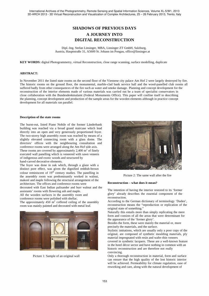
KEY WORDS: digital Photogrammetry, virtual Reconstruction, close range scanning, surface modelling, duplicate ABSTRACT: In November 2011 the listed state rooms on the second floor of the Viennese city palace Am Hof 2 were largely destroyed by fire. The historic rooms on the ground floor, the monumental, marble-clad bank service hall and the wood-panelled club rooms all suffered badly from other consequences of the fire such as water and smoke damage. Planning and concept development for the reconstruction of the interior elements made of various materials was carried out be a team of specialist conservators in close collaboration with the Bundesdenkmalamt (Federal Monuments Office). This paper will confine itself to describing the planning, concept development and production of the sample areas for the wooden elements although in practice concept development for all materials ran parallel. Description of the state rooms The burnt-out, listed Piano Nobile of the former Länderbank building was reached via a broad grand staircase which lead directly into an open and very generously proportioned foyer. The two-storey high assembly room was reached by means of a slightly elevated connecting room with a glass dome. The directors’ offices with the neighbouring consultation and conference rooms were arranged along the Am Hof side axis. These rooms are covered by approximately 2,400 m2 of finely executed wall panelling which is veneered with sawn veneers of indigenous and exotic woods and structured by hand-carved decorative elements. The foyer was done in oak which, through a glaze with a distinct pore effect, was given the dignified reddish-brown colour reminiscent of 19th century studies. The panelling in the assembly room was predominantly worked in walnut, makoré and maple following the structural arrangement of the architecture. The offices and conference rooms were decorated with East Indian palisander and burr walnut and the assistants’ rooms with flowering ash and maple. All the wooden surfaces in the assembly room and conference rooms were polished with shellac. The approximately 450 m2 coffered ceiling of the assembly room was mainly painted and decorated with metal leaf.
Picture 1: Sample of an original wall
Picture 2: The same wall after the fire
Reconstruction – what does it mean? The intention of having the interior restored to its ‘former glory’ already describes the essential component of the reconstruction. According to the German dictionary of terminology ‘Duden’, reconstruction means the “reproduction or replication of the original state of something.” Naturally this entails more than simply replicating the mere form and consists of all the areas that were determinant for the appearance of the ‘former glory’. Besides the form, these were mainly the material or, more precisely the materials, and the surface. Stylistic imitations, which are usually only a poor copy of the original, are composed of synthetic moulding materials, ply material impregnated with resin and wafer-thin veneers covered in synthetic lacquers. These are a well-known feature in the hotel décor sector and have nothing in common with an historic reconstruction and are therefore not really convincing. Only a thorough reconstruction in material, form and surface can ensure that the high quality of the lost historic interior will be achieved. Permeability for climate regulation, ease of reworking and care, along with the natural development of
International Archives of the Photogrammetry, Remote Sensing and Spatial Information Sciences, Volume XL-5/W1, 20133D-ARCH 2013 - 3D Virtual Reconstruction and Visualization of Complex Architectures, 25 – 26 February 2013, Trento, Italy
153
patina, are just as much guaranteed by the use of historic materials as are the typical flair and pleasing spatial feel associated with historic interiors created with a combination of natural materials. Reconstruction is based on the analysis of precise investigative examination and is at best applied art technology which upholds the know-how of historic technology and the skills of historic material processing. What bases exist? The reconstruction of the state rooms can draw upon a detailed conservation examination of approximately 500 sides that we produced in 2010 to draft a concept for the conservation and restoration. It contains a room for room precise description of the interior elements based on their technical construction and ornamental moulding, and a list of the materials that had been employed. Layered analysis of the polychromed surfaces was done to examine the pigments and binder with various scientific methods. It was not foreseeable at the time that the detailed mapping of the damage to the walls were to prove dispensable. The high resolution ortho photographs which provided the basis for the damage mapping are, however, an essential source of information for the reconstruction. The special photographic technique provides information which is extremely useful for a 3D analysis. (This will subsequently be described more precisely.) The importance of the large number of detail photographs that were made preliminary to the restoration and the available historic photographs should not be underestimated as a source of information for the preparation of the reconstruction. It was also essential to salvage every surviving charred remnant of the construction elements after the fire and to record their position in the mapping documentation and the sections for further evaluation. From 3D visualisation to reconstruction in material, form and surface commensurate with the quality of the original interior
Despite the large amount of information available in the documentation, we are still a long way from a basis to make the necessary plans for a reconstruction project to be executed in the desired quality within a period of only one and a half years. The interest in seeing the result of a possible reconstruction before execution commences is so great nowadays with perception being loaded with virtual images that the virtual representation itself actually produces the conviction that the reconstruction is feasible. The 3D real-time model produced by two companies, Firma Linsinger and a:xperience Wien, based on the ortho photographs they took in 2010, is so convincing that the reconstruction seems almost tangible. Visitors can, as it were, place themselves in the rooms and change their position and zoom in or out on areas and so select the detail of their choice This model, which does not have to fit into any real structure, lacks evaluable dimensions which are produced with sectional drawings and have to agree with a surveyor’s plan. The analysis of ortho photographs is not sufficient to represent the real form of the decorative details such as capitals and ornamental friezes.
Production of the scale drawings for the reconstruction
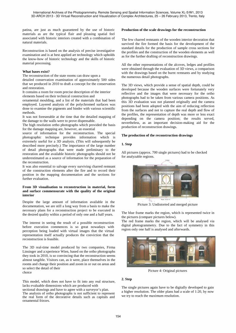
The few charred remnants of the wooden interior decoration that survived the fire formed the basis for the development of the standard details for the production of sample cross sections for the profiles and the construction of the wooden elements as well as for the further drafting of reconstruction drawings. All the other representations of the alcoves, ledges and profiles were obtained through the evaluation of 3D views, a comparison with the drawings based on the burnt remnants and by studying the numerous detail photographs. The 3D views, which provide a sense of spatial depth, could be developed because the wooden surfaces were fortunately very reflective and the images that were necessary for the ortho photographs had to be taken from various camera positions. As this 3D evaluation was not planned originally and the camera positions had been adopted with the aim of reducing reflection from the surfaces and not to capture the real depth and flow of the profiles, the representation of depth was more or less exact depending on the camera position; the results served, nevertheless, as an important decision-making aid for the production of reconstruction drawings. The production of the reconstruction drawings 1. Step All pictures (approx. 700 single pictures) had to be checked for analyzable regions.
Picture 3: Undistorted and merged picture
The blue frame marks the region, which is represented twice in the pictures (compare pictures below). The red frame marks the region, which will be analysed via digital photogrammetry. Due to the fact of symmetry in this region only one half is analysed and afterwards.
Picture 4: Original pictures
2. Step The single pictures again have to be digitally developed to gain a higher resolution. The older plans had a scale of 1:20, by now we try to reach the maximum resolution.
International Archives of the Photogrammetry, Remote Sensing and Spatial Information Sciences, Volume XL-5/W1, 20133D-ARCH 2013 - 3D Virtual Reconstruction and Visualization of Complex Architectures, 25 – 26 February 2013, Trento, Italy
154
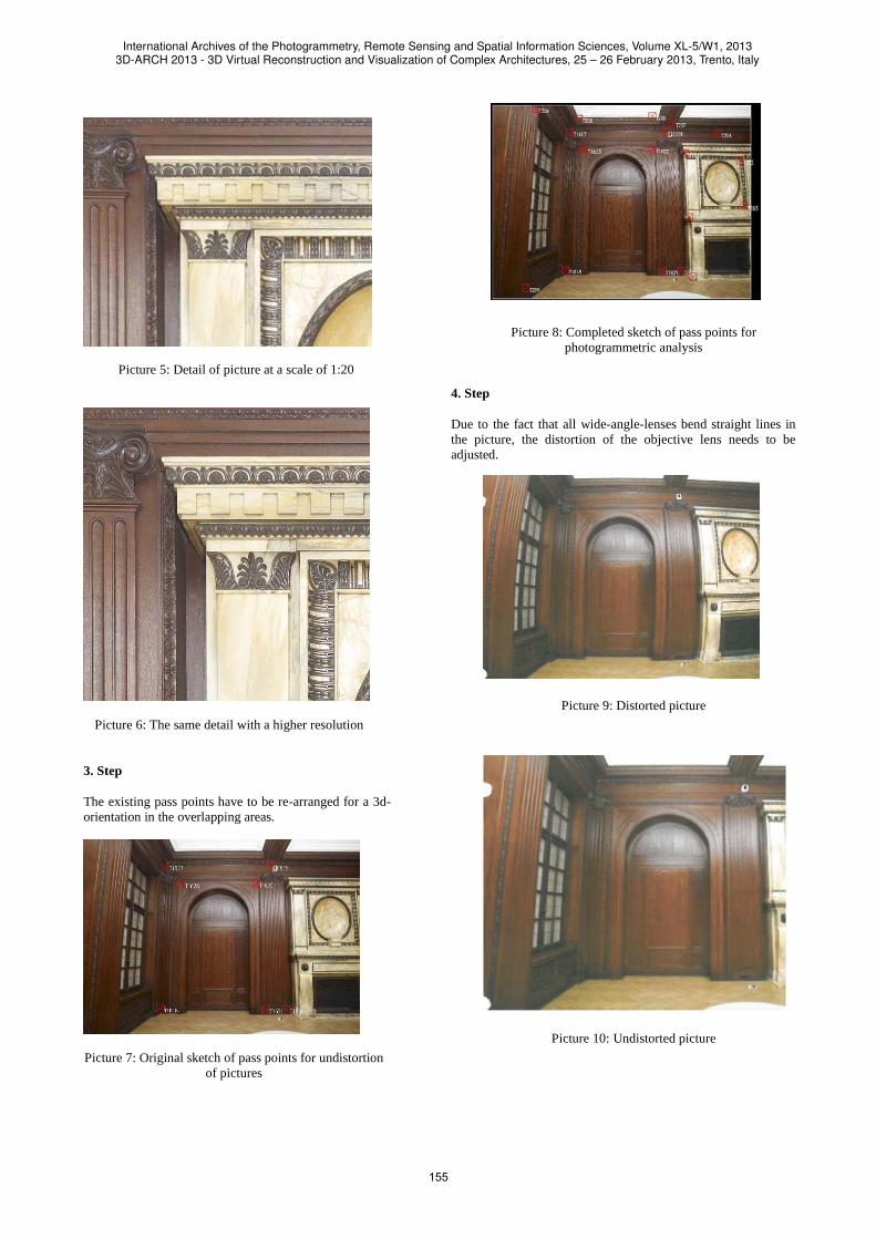
Picture 5: Detail of picture at a scale of 1:20
Picture 6: The same detail with a higher resolution 3. Step The existing pass points have to be re-arranged for a 3d-orientation in the overlapping areas.
Picture 7: Original sketch of pass points for undistortion
of pictures
Picture 8: Completed sketch of pass points for
photogrammetric analysis 4. Step Due to the fact that all wide-angle-lenses bend straight lines in the picture, the distortion of the objective lens needs to be adjusted.
Picture 9: Distorted picture
Picture 10: Undistorted picture
International Archives of the Photogrammetry, Remote Sensing and Spatial Information Sciences, Volume XL-5/W1, 20133D-ARCH 2013 - 3D Virtual Reconstruction and Visualization of Complex Architectures, 25 – 26 February 2013, Trento, Italy
155

Photogrammetric analysis 5. Step (orientation of pictures) The pictures with an overlapping region are analysed with a digital photogrammetric station to generate 3d-coordinates. Therefore each picture needs to be oriented to calculate the position of the camera.
Picture 11: Photogrammetric station
6. Step (Analysis of the former condition in 3d) Each edge and contour is analysed by joystick in 3d to generate coordinates in x,y and z.
Picture 12: Work status during analysis
Picture 13: Final analysis
7. Step (Analysis of the cutting line in the former condition) Through each profile a cutting line has to be created, which builds the base for a development in depth.
Picture 14: Cutting line through column
Picture 15: Resulting horizontal section
8. Step (Idealisation of the generated model) This step generates a consistent model with horizontal and vertical elements unless they are bended or aslope.
Picture 16: Original analysis
International Archives of the Photogrammetry, Remote Sensing and Spatial Information Sciences, Volume XL-5/W1, 20133D-ARCH 2013 - 3D Virtual Reconstruction and Visualization of Complex Architectures, 25 – 26 February 2013, Trento, Italy
156

Picture 17: Idealised elements (green)
3D-MODELLING 9. Step (Modelling of surfaces) So far there are 3d-lines but no surfaces as base for reconstruction. Using the existing 3d-lines, profile sections and the undistorted pictures a surface model is going to be created.
Pictures 18/19: Examples of a 3d modelling
10. Step (Modelling of details)
Using special programs several details can be recreated up to a certain point. These details surely need a post-processing by a sculptor before leading to automatic mass production. 3D-Scan and duplication with CNC mill 11. Step (Creation of a sample item by sculptor) As already mentioned the best result for complex elements like capitals probably can be achieved only by a sculptural reproduction. 12. Step (3d-scan with a close range scanner) The sculptural reproduction afterwards is scanned with a close range scanner. The post processing generates a „water tight“ completely closed 3d model of the object. The following is an example for scanning and milling: Castle Belvedere, Figures of Hercules
Pictures 20/21: Base for duplication
International Archives of the Photogrammetry, Remote Sensing and Spatial Information Sciences, Volume XL-5/W1, 20133D-ARCH 2013 - 3D Virtual Reconstruction and Visualization of Complex Architectures, 25 – 26 February 2013, Trento, Italy
157

Picture 22: Water tight 3d model
Picture 23: Milled duplication in PU-foam
The reconstruction drawings were all produced in ACAD and contain all the views and sections of the rooms to be reconstructed: the assembly room, the foyer with the staircase and the conference rooms with adjoining rooms. Additional information was attached to the drawings as text descriptions of the examination results and the definition of the materials (panel sheet, solid wood, saw-cut veneer, type of wood, texture, veneer orientation, binder). A total of 2,400m2 of wall panelling was drawn true to detail on the basis of the information mentioned above and brought into agreement with the surveyor’s plan prior to the fire and, in the form of a scatter plot, with the surveyor’s record of the state after the fire. The surveyor’s plan prior to the fire took the edge of the wall decoration most to the fore as a reference, the scatter plot after the fire took only the actual
surviving construction elements which differed vastly from the surveyor’s plan as most of the partition walls had been destroyed in the conflagration. As all of the rooms are connected with each other, the thickness of the walls and the size and position of the window and door openings also influence the geometric arrangement of the wall panelling of the neighbouring rooms.
In contrast to the virtual reconstruction, everything in the material reconstruction has to fit into the burnt-out shells of the rooms and has to look exactly as it did before as well.
New approaches to the development and planning of the decorative areas (capitals, carved decoration, decorative beading) The reconstruction drawings precisely define the views and the depths of the projections and recesses of the profiles flow. The decorative areas can neither be sufficiently developed nor represented in the 2-dimensional system of views and sections. The conventional approach to a reconstruction of ornamental parts is by dint of photographs as a basis for form which is modelled in clay, wax or other modelling materials and then transposed into the type of wood used for the original. This procedure is the usual one for the reconstruction of individual pieces and small series. As an interim stage, the use of a scanned model and copying milling machine is helpful. Finishing work by hand is reduced to completing the under carving and ornamental fine detail of the decoration. In our case we are not dealing with individual pieces but with hundreds of decorative elements and kilometres of carved decorative beading. Apart from the costs of doing it all by hand, the amount of work involved in the time available would be practically impossible. The method we and our partners have chosen to adopt combines the evaluation of 3D image data with computer generated modelling based on drawings done by hand from detail photographs. In this instance, the sculptor does not model in clay but directly on the computer, adjusting or correcting the form virtually until it is right. Using 3D drawing programs, the basic structure of the object is first generated to scale with a modelling program (3Dmax, Maya). Then using a 3D tool such as zBrush, Mudbox the basic object can be drawn on directly and distorted in three dimensions. This can best be imagined like using the airbrush technique but in three dimensions. The result can be examined and corrected immediately. At the end of the modelling work there is a 3D mesh (e.g. an OBJ file) which compactly defines the complete object for the following CNC milling. This data can be sent directly, also as an email, to the executing company (between 200 kB and 20 MB per object), which then produces a blank with the computer-operated 3-axis and 5- axis milling machines in polyurethane rigid foam. The polyurethane model is the tangible result of the preparatory work. The dimensions can be checked with the CAD drawings to ensure that the decorative elements actually fit into the position they are intended for. If the result is already very close to the original, the decorative fine detail and the under carving will be worked by hand using traditional carving tools. If more drastic sculptural corrections are necessary to approximate the original more closely, the reworked polyurethane model is scanned with a stripe light scanner and saved as a 3D packet in the computer modelling format.
International Archives of the Photogrammetry, Remote Sensing and Spatial Information Sciences, Volume XL-5/W1, 20133D-ARCH 2013 - 3D Virtual Reconstruction and Visualization of Complex Architectures, 25 – 26 February 2013, Trento, Italy
158
If the polyurethane model complies with expectations and no alterations and adaption need to be made at the computer modelling level which would demand realigning the 3D data, then the goal has been reached and the master form with its 3D data becomes the production pattern for all further copies in the type of wood used in the original. There is another decisive advantage in computer-based modelling. The decorative elements can be fitted with minimal compression or stretching so that the mitre joints of the corner ornaments fit together perfectly and the length of the profile bands corresponds with the repeats of the ornaments – and this all happens during the planning phase!
Production of reference samples and the sample wall As early as during the early planning phase the Federal Monuments Office (BDA) and the client prompted the production of a sample wall with the adjoining ceiling area and floor intersection to be executed in material, form and surface commensurate with the original interior. The clear position of the Federal Monuments Office that it would only agree to a reconstruction if it were executed based on the guidelines of cultural heritage preservation and in the best quality set the tone. Reconstruction on the highest level or completely new design – that was the Federal Monuments Office’s stand point. The choice of the area for the sample wall was the south wall of the foyer, which was named the ‘Franz Josef wall’ due to a bust of the Austrian Emperor Franz Josef I inserted into niche above the fireplace. The combination of various materials, like the metal applications on the monumental open marble fireplace, the circa 10m long and 5m high wooden panelling with architectural structuring, entrances and richly ornamental carving and the stucco fields integrated into the adjoining wooden ceiling all make this wall particularly attractive. The aim was to test whether a reconstruction utilising historic art technology corresponding to basic findings and planning would be feasible in a tight timeframe and to see what results might be expected.
The historic structure of the sample wall is as follows:
Underlying construction: spruce Supporting construction: panels: single strips of spruce, structural veneer in ceiba glued with casein glue.Thicknesses 8mm, 10mm and 24mm
Solid wood: oak; glued with animal glue Veneer: sawn veneer ca.1,5mm; in oak stuck to the levelled supporting boards with animal glue
Surfaces: staining, oil glaze with natural resin varnish (Cassel brown, natural resin varnish), oil glaze for a defined pore effect (linseed oil, tung oil, earth pigments), thin wax matting agent
The wood work of the sample wall was done by us and two other companies of our choice.
We were responsible for the production of the reference sample for the sample wall in compliance with the historic structure including the surfaces reconstructed on the basis of the scientific examinations. The 3D modelling of the decorative elements with sculpted reworking of the master pattern were already available for the sample wall at this juncture. The partner companies realised this concept using our planning and execution data and worked out methods to incorporate partially automated production stages to rationalise the historic working techniques. A high degree of hand crafting was ensured in this way. Our function was to coordinate the completed working stages, to ensure quality through comparison with the original and consistency of colour after the decorative elements had been mounted on the sample wall. The panels were constructed from specially selected spruce and glued with casein glue. The saw-cut veneer was, corresponding to the ortho photographs, cut from choice blocks of oak using a muley saw and glued onto the supporting board with animal glue. The decorative elements were pre-cut on the basis of 3D data with a CNC milling machine and then reworked by hand. These individual parts were given a surface consistent with the original and prepared for delivery. After they had been mounted in situ, we were responsible for the subtle agreement of colour between the parts.
Presentation of the project tool for collecting data, documentation of working stages and the coordination of collaborators Before I conclude, I would like to comment on the working tool which accompanied us behind the scenes. Tailored to the user’s needs as a virtual communication tool, it brings order in a simple way to the confusing flood of data and documentation which generally come with examination, documentation, restoration and reconstruction projects of this magnitude. All relevant information available at any given time can be fed into this tool using an attractive user interface. They are thus made readily available to all the project partners involved in an ordered form either in an offline or online version. In line with the work progress of the collaborating partners, documents that have been worked upon are put into the tool. These can then be used as a working basis by everybody. In this particular instance, we had easy access to a ortho photograph with a view of the wall before the fire and could compare it immediately with the CAD drawing which had been made for the reconstruction. If one is interested in the surface finish, then all one has to do is to look for the relevant scientific report; if one wants to look at an ornament in detail, one simply opens the corresponding 3D modulation and turns the ornament to the position one wants to look at. The 3D data necessary for the production of the ornament are to be found in the assigned ornament list and can be downloaded from there by the executing company. If one wants to read through the description of the relevant wall, one only has to open the examination report stored in the archive and retrieve the data about the wall by using the search function. This fast and ready access to information at the most up-to- date stage in the reconstruction is not only useful for the management of the project but also for ensuring quality consistency during both the planning and execution phase.
International Archives of the Photogrammetry, Remote Sensing and Spatial Information Sciences, Volume XL-5/W1, 20133D-ARCH 2013 - 3D Virtual Reconstruction and Visualization of Complex Architectures, 25 – 26 February 2013, Trento, Italy
159
It provides an individual overview of the appointments or deadlines to be kept and the level of completion of the work taken on by each collaborator. This means that one can see when preparatory work is likely to be completed and whether access to the information produced by other project partners is available. A mobile gateway was developed for use on site which also made all of the functions and data available on either a tablet computer or Smartphone. The developed PM software already proved its worth during the planning phase and, with a few additional modules, will also be highly suitable for ensuring efficient and direct monitoring with up-to-date information access during the execution phase. The groundwork has been completed with all data having been fed into the working tool. The exemplary completion of the sample wall confirms that a reconstruction in material, form and surface commensurate with the original is possible and that execution within a very narrow timeframe will be possible using selected specialised companies with the necessary skilled craftsmanship resources. Preparation of the tender All documents of the groundwork will find their way into the documents for the tender. Execution will be divided into three packages of ca. 800m2 of wall panelling and no more than a year is allowed for completion. The tender has been conceived as a two stage process of invitation with the first stage being intended to ascertain the fundamental suitability, efficiency and capacity of the potential companies and the second stage reserved for determining the best bidder on the basis of a sample of ca. 2m2 in size and for establishing priced specifications. Conclusion In little more than a year the state rooms of Am Hof 2 will rise from the ashes to their ‘former glory’ as a reconstruction in form, material and surface. We would like to invite you all to come and see the result in a good year from now.
International Archives of the Photogrammetry, Remote Sensing and Spatial Information Sciences, Volume XL-5/W1, 20133D-ARCH 2013 - 3D Virtual Reconstruction and Visualization of Complex Architectures, 25 – 26 February 2013, Trento, Italy
160