shape and sizing optimization of box-girder decks of · pdf fileshape and sizing optimization...
TRANSCRIPT

Shape and sizing optimization of box-girder
decks of cable-stayed bridges
J.H. Negrao, L.M.C. SimoesDepartment of Civil Engineering, University ofCoimbra, 3049 CoimbraCODEX, PortugalEmail: jhnegrao@dec. uc.pt
Abstract
Box-girder cross-sections are characterized by large torsional stiffness whencompared with alternative solutions. This is a fundamental issue as the bridgespan increases. Transverse winds may lead to critical stress conditions or cause anumber of aerodynamic instability phenomena, which are related to the torsionalstiffness of the deck. Moreover, in single-plane stayed bridges, the use of box-girder decks is dictated by equilibrium requirements.The definition of the cross-section may be rather complex. There are a largenumber of parameters involved, load combinations, critical stress locations andthe dependence of the wind loading or seismic response on the geometric andstiffness characteristics of the deck.Mathematical programming techniques may thus be valuable tools to assessdesigner expertise in the preliminary design stage. In this paper, one such studyis undertaken. Plate thickness and size of the box-girder, cross-sectional area andprestress in stays, anchorage positions and cross-sectional parameters of thepylons are the continuous design variables considered. The optimization problemis stated as the minimization of stresses, displacements and the bridge cost. Afinite-element approach is used for structural analysis. It includes a directanalytic sensitivity analysis module that provides the structural behaviourresponses to changes in the values of the design variables.An equivalent multicriteria approach is used to solve the non-differentiable non-linear optimization problem, turning the original problem into the sequentialminimization of unconstrained convex scalar functions, from which a Paretooptimum is obtained. An illustrative example is presented.
Transactions on the Built Environment vol 37 © 1999 WIT Press, www.witpress.com, ISSN 1743-3509

324 Computer Aided Optimum Design of Structures
1 Introduction
Preliminary design of cable-stayed bridges is usually undertaken by the so-calledpendulum method, e.g.Virlogeux*. The bridge deck is assumed to behave like amulti-span continuous beam laying on sloping supports which represent thesuspending effect of the stays. These are assumed to be rigid, in order to matchthe undetected shape required for dead load condition. This can be ensured byproperly prestressing the stays during the erection stages. The values of theactual installing forces are determined by dismantling and back-analysing theresulting temporary structures, in an order opposite to that of the erection.From a mechanical point of view this procedure leads to a nearly optimumdesign under dead load condition. In fact, bending on deck is reduced to theunavoidable local effect related to cable spacing. Thus, load is transferred tofoundation mostly by axial force (tension in stays and compression in deck),which is the most effective way for using the available material. Besides, if asymmetric cable arrangement is used, forces in cables of opposite sides of thepylon are balanced and bending stresses in pylons also vanish.However, this almost ideal behaviour no longer applies under the action of live,seismic and wind loads. These lead to a much less predictable stress envelope.Therefore, one can not ensure that the preliminary design based on the dead loadeffects will still be the best suited to those stresses, which actually determine thedesign.Another important issue is that the traditional preliminary design provides noinformation on the best distribution of material for deck, where most of thestructural mass is concentrated. This problem is especially complex with box-girder decks, due to its elaborated geometry and three-dimensional nature. Theuse of such structural solution becomes more and more frequent, as the averagespan of cable-stayed bridges increases or simply because of fundamentalequilibrium requirements, as is the case with bridges with a single plane of stays.The purpose of this paper is to show the potential of mathematical programmingtools for providing suitable solutions for this problem. The optimization problemis posed as that of the minimization of structural cost, subjected to constraints onmaximum stresses throughout the structure, non-slackness conditions for thestays and dead load geometry matching for the deck. Although the aspectsconcerning the optimal size and shape of the deck are emphasised, issuesconcerning other structural parts are also referred to, because neither part of thestructure can be optimized on its own.
2 Design variables
There are a wide variety of parameters that play an important role in thestructural behaviour of a cable-stayed bridge, and a virtually endless number ofpossible combinations of their values. Each of those requires specific numericprocedures for sensitivity analysis. The least time-consuming way to specify astarting trial design and the set of associated design variables is by referring to adesign variable library, e.g. Negrao and Simoes , Simoes and Negrao . From
Transactions on the Built Environment vol 37 © 1999 WIT Press, www.witpress.com, ISSN 1743-3509

Computer Aided Optimum Design of Structures 325
this the appropriate procedures are selected by simply defining links between theelement mesh and the desired design variable.
16
21
2%
H1 21
i
18
*•• 1
i—"—i
3
&4
Figure 1: Sizing design variables
Figure 2: Shape and mechanical design variables
Figures 1-2 show the current contents of this library. Sizing design variablesdirectly lead to weight (or cost) reduction. Its presence in the design variable setis therefore unavoidable for that purpose. Mechanical and geometric designvariables are almost cost insensitive but allow for better stress distributions,which in turn lead to additional reductions in sizing variables. Other importantfeature of the latter is that they require remeshing after each analysis-optimization cycle, because they produce changes on nodal co-ordinates or evenon element connections. Design variable types 20 and 21 are hybrid, because itsuse results in nodal co-ordinates updating but produces no changes in elementconnections and numbers.Among the several descriptive parameters of the structure, cross section area andinitial prestress of the stays play a fundamental role on the stress distributionthroughout the structure, because they determine the extent of the beam-likebehaviour of the deck. Besides, they are essential for a successful deflectioncontrol, which otherwise could only be achieved by a severe stiffening of the
Transactions on the Built Environment vol 37 © 1999 WIT Press, www.witpress.com, ISSN 1743-3509

326 Computer Aided Optimum Design of Structures
deck, in opposition to the expected reduction of material. Therefore, its use asdesign variables is essential in any optimization procedure.
3 Sensitivity analysis
Given the availability of the F.E. analysis code and the better accuracy, ananalytical procedure was chosen for sensitivity analysis. The discrete nature ofthe structural topology and the large number of constraints under control dictatedthe choice of the discrete direct method. In this, the sensitivities of displacementsare obtained from the differentiation at the element level of the stiffness methodequilibrium equations.
^=f-f" ™dx dx dx
Derivatives of stiffness matrix, right-hand sides and strain-displacementsmatrices and vectors are explicitly coded at the element routines and arecomputed simultaneously with the quantities required for analysis. Designvariables of types 20 and 21 (see Figure 2) show the particular issue of affectingthe local axes cosines of some deck elements, as shown in Figure 3. This impliesthe use of an extended expression for the derivative of the stiffness matrix, inwhich the variation of the transformation matrix is accounted for:
dx ~ ~ ~ dx (2)
JLI
Figure 3: Dependancy of local axes cosines on design variables of types 20-21
Sensitivities of stresses are obtained by derivation of the stress-displacementrelation
da _ dD dB du
dx dx ~ dx dx
The first two contributions in equation (3) become readily available from thesolution of the ordinary analysis problem and are therefore called explicit. Thelast term further requires the solution of the pseudo-loading system (1) and isreferred to as implicit. Explicit terms reflect mostly the local effect of changesof sizing variables, while implicit term represents the overall effect.
Transactions on the Built Environment vol 37 © 1999 WIT Press, www.witpress.com, ISSN 1743-3509

Computer Aided Optimum Design of Structures 327
4 Optimization
The optimization problem is stated as that of the minimization of structural cost(or volume) and the maximum stresses throughout the structure. Additionalobjectives are aimed at the deflections at selected points, namely the anchoragenodes of the stays on deck and horizontal displacements at the top of the pylons.These criteria are essential to ensure that the optimized design will match thedead load condition. Another important set of objectives concerns the non-slackness condition for the stays. They intend to prevent the loss of structuraleffectiveness that may result from a low tensile strength under certain load cases,or even meaningless situations such as compression in some stays.This is a minimax problem, which is discontinuous and non-differentiable andthus difficult to solve. However, by using the concept of entropy, Templeman^has shown that the solution of this problem is the same of that of theminimization of a non-linear convex scalar unconstrained function, which maybe much easily solved by conventional NLP methods. This function is:
With these conflicting objectives, the algorithm supplies a minimum in thePareto sense. Thus, a few starting trial designs may be used for the sake ofcomparison of alternative solutions. M is the number of constraints, p is a controlparameter that must be steadily increased as the current function valueapproaches the optimum.For numerical purposes, equation (4) is replaced by the following approximation:
v_/ p er
J
(5)
In (5), first order estimates of the current values of the constraints are computedby using the sensitivities provided by the solution of equations (1) and (3).
5 Numerical example
In order to illustrate the potential of this method, the symmetrical three-spancable-stayed bridge represented in Figure 4 was studied. The large span andmulti-cable semi-harp pattern is representative of the present trend on suchstructures. There were no exhaustive studies for the selection of the preliminarydesign, only reasonable conditions concerning aesthetics and element sizingbeing accounted for. This is because the algorithm itself will naturally lead to afeasible design with respect to stresses and selected deflections.
Transactions on the Built Environment vol 37 © 1999 WIT Press, www.witpress.com, ISSN 1743-3509

328 Computer Aided Optimum Design of Structures
165 405 165
Figure 4: Geometry of the model
Torsional stiffness and aerodynamic stability requirements dictated the choice ofa box-girder solution for the deck. A 24m width was considered in order toaccommodate 6 lanes of traffic. Two intermediate septs divide the bottom faceinto three equal panels. Diaphragms are placed every 15m, to coincide with thepositions of cable anchorages. Assuming a steel deck, an equivalent thicknesshad to be used to match the true cross-sectional area and inertia of the ribbedpanels. By using fictitious values of uniform thickness, Young's modulus andmass, the actual bending and axial stiffness and self-weight values werepreserved. The unit cost for the deck is adapted accordingly. Yield stresses of200MPa were used for the deck and pylons and SOOMPa for the stays. Allelement types were assigned the unit volume cost of 1, which is, in some degree,an arbitrary choice.Three load cases were accounted for the sake of ultimate limit state design: liveload throughout the deck, on side spans and on central span only. A uniformlydistributed load of 6KN/nf was assigned to non-structural dead load such as thebituminous layer and fixed equipment. As to the live traffic load, a value of4KN/nf was prescribed. This is obviously a minimalist approach, because windand/or earthquake may in some instances be dominating in the design of suchlong bridges. However, the essential features and purposes of this paper wouldnot significantly be emphasised by its inclusion and thus they were discarded,though the software is prepared to handle them. An additional case of dead loadwas also included to provide the kinematic constraints concerning the sub-problem of geometry matching.Initial tensile fixed-end forces were prescribed for the stays. These have not apractical meaning, but they affect the erection initial stress to put the cable inplace. They play a fundamental role in both controlling the deflections andproviding for optimal stress distributions on deck and pylons. Differently fromother structural parameters, their direct impact on the overall structural cost isnot a function of a unit material cost but, instead, that concerning to the prestres-
Transactions on the Built Environment vol 37 © 1999 WIT Press, www.witpress.com, ISSN 1743-3509

Computer Aided Optimum Design of Structures 329
sing equipment and staff.The design variable set consists of 78 parameters:
• upper, bottom and side panel thicknesses in side span, central span andneighbourhood of pylons (#1-9)
* diaphragm thickness (# 10)• deck height and bottom width for the whole span (#11-12)+ sizes and thicknesses of the pylon panels for the lower, intermediate and
upper stages (#13-24)• cables cross-sectional areas (#25-50)• cables fixed-end prestressing force (#51 -76)• distance between the deck and the lower cable anchorage in pylons (#77)• length of the anchorage region of cables in the pylons (#78)
The values of the design variables are as indicated in Table 1.
Table 1 - Starting and optimal values of design variables
VD
1234567891011121314151617181920212223242526
Xini
10.010.010.010.010.010.010.010.010.010.01.5021.005.005.005.05.04.504.504.04.04.004.004.04.0200200
Xopt
5.85.819.36.67.17.15.05.011.55.01.4122.507.007.008.08.06406.006.06.05.005.006.06.0251257
VD
2728293031323334353637383940414243444546474849505152
Xini
20020020020020020020020020020020020020020020020020020020020020020020020020002000
Xopt
20618911410991108173174137122769710010712513216512612619521721219916653325519
VD
5354555657585960616263646566676869707172737475767778
Xini
20002000200020002000200020002000200020002000200020002000200020002000200020002000200020002000200052.5030.00
Xopt
45234157252023812006248042744671396437132332261024652437263323563102229922673521400040003873335164.5025.82
Transactions on the Built Environment vol 37 © 1999 WIT Press, www.witpress.com, ISSN 1743-3509

330 Computer Aided Optimum Design of Structures
The overall cost reduction achieved was about 16% of the initial cost. This valuestrongly depends on how much the minimum feasibility level was exceeded bythe trial starting design. Thus, the important issue to highlight is the higheffectiveness of the solution provided by the algorithm. The optimization of thedeck shape and size, which is one of the main goals of this paper, resulted in onlyslight changes on shape but in large variations of plate thicknesses. Therelatively sharp profile is a consequence of neglecting the quasi-static oraerodynamic wind effects. In such conditions, the nearly vertical slope of thelateral septs enhances the capability to carry the high cable anchorage forces andmaximizes bending stiffness at the cost of almost no extra material. Figure 5shows the starting and optimized shapes of the deck for the three regionsconsidered.
Starting design (uniform) Pylons neighbourhood
I Scales: Width : Height: Thickness = 10:2.5 : 1
Side span Central span
Figure 5: Comparative shapes and sizes for the deck
As to the height of the pylons, a steady trend towards the fan pattern was noticedthroughout the optimization process, with anchorages getting closer and higherfrom iteration to iteration, which enhances the effectiveness of the cables aselastic supports for the deck. In Figure 6 one may compare the starting andoptimized profile of the bridge.
Optimized geometryStarting geometry
Figure 6: Comparison between starting and optimized geometry
Transactions on the Built Environment vol 37 © 1999 WIT Press, www.witpress.com, ISSN 1743-3509
Computer Aided Optimum Design of Structures 331
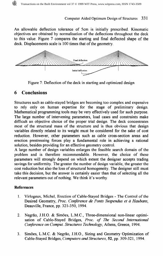
An allowable deflection tolerance of 5cm is initially prescribed. Kinematicobjectives are obtained by normalisation of the deflections throughout the deckto this value. Figure 7 compares the starting and final deflected shape of thedeck. Displacements scale is 100 times that of the geometry.
Figure 7: Deflection of the deck in starting and optimized design
6 Conclusions
Structures such as cable-stayed bridges are becoming too complex and expensiveto rely only on human expertise for the stage of preliminary design.Mathematical programming tools may be very effectively used for such purpose.The large number of intervening parameters, load cases and constraints makedifficult an objective choice of the proper trial design. The deck concentratesmost of the structural mass of the structure and is thus obvious that designvariables directly related to its weight must be considered for the sake of costreduction. However, other parameters such as cable cross-section areas anderection prestressing forces play a fundamental role in achieving a rationalsolution, besides providing for an effective geometry control.A large number of design variables enlarges the feasible search domain of theproblem and is therefore recommendable. However, the choice of theseparameters will strongly depend on which extent the designer accepts tradingsavings for uniformity. The greater the number of design variable, the greater thecost reduction but also the loss of structural homogeneity. The designer still musttake this decision, but the answer is certainly easier than that of selecting all therelevant parameters out of nothing. We think it's worthy.
References
1. Virlogeux, Michel, Erection of Cable-Stayed Bridges - The Control of theDesired Geometry, Proc. Conference de Fonts Smpendus et a Haubans,Deauville, France, pp. 321-350, 1994.
2. Negr&o, J.H.O. & Simoes, L.M.C., Three-dimensional non-linear optimi-sation of Cable-Stayed Bridges, Proc. of The Second InternationalConference on Comput. Structures Technology, Athens, Greece, 1994.
3. Simoes, L.M.C. & Negrao, J.H.O., Sizing and Geometry Optimization ofCable-Stayed Bridges, Computers and Structures, 52, pp. 309-321, 1994.
Transactions on the Built Environment vol 37 © 1999 WIT Press, www.witpress.com, ISSN 1743-3509

332 Computer Aided Optimum Design of Structures
4. Negrao, J.H.O. & Simoes, L.M.C., Optimisation of Cable-Stayed Bridgeswith Three Dimensional Modelling, Computers and Structures, 64, pp.741-758, 1997.
5. Simoes, L.M.C. & Negrao, J.H.O., Optimization of Cable-Stayed bridgeswith Box-Girder Decks, Proc. Fifth Int. Conference on Computer AidedOptimum Design of Structures, Rome, Italy, pp. 21-32, 1997.
6. Templeman, AB, Entropy-based optimization methods for engineeringdesign, Advanced Techniques in the Optimum Design of Structures, Topicsin Enginnering, ed. S. Hernandez, vol.12, Computational MechanicsPublications, U.K., pp. 109-139, 1993.
Transactions on the Built Environment vol 37 © 1999 WIT Press, www.witpress.com, ISSN 1743-3509