sharing deliverable d6.3 - localization architecture for multi-layer
TRANSCRIPT
Public/Confidential page 1 of 41
SHARING
SELF-ORGANIZED HETEROGENEOUS ADVANCED RADIO NETWORKS GENERATION
Deliverable D6.3
Localization architecture for multi-layer, multi-RAT heterogeneous
network
Date of delivery 23/02/2015
Contractual date of delivery 28/02/2015
Project number C2012/1-8
Editor(s) Jussi Turkka (MAG)
Author(s) Jussi Turkka (MAG), Tapani Ristaniemi (MAG)
Dissemination level PU/RE/CO
Workpackage 6
Version v1.0
Total number of pages 41
Abstract:
Keywords: Network architecture, Location estimation, LTE/WLAN interworking
This deliverable proposes a generic measurement framework for enabling localization
in multi-layer, multi-RAT heterogeneous networks using the Radio Frequency (RF)
fingerprinting methodology. The aim of the proposed architecture is to enhance the
geographical location of Minimization of Drive Tests (MDT) measurements rather than
the geographical location of User Equipment (UE) itself, knowing that ultimately this
improvement will benefit both purposes. Two alternative solutions are proposed, a
control-plane solution and a user-plane solution. The perspectives and constraints of
these solutions are discussed highlighting the importance of having a generic
automated measurement framework for different applications such as RF fingerprint
localization, coverage mapping for Wireless Local Area Networks (WLAN), access
network discovery and selection, and network based proximity indication.
Performance evaluation of the proposed architecture was carried out by conducting
system simulations and measurements in a live Long Term Evolution (LTE) network.
Simulation and measurement results suggest that by correlating MDT measurement
with detectable WLAN measurements, location precision can be significantly
improved.
Celtic-Plus SHARING Document D.6.3
Public/Confidential page 2 of 41
Document Revision History
Version Date Author Summary of main changes
0.1 1.9.2014 Jussi Turkka ToC drafted
0.2 5.12.2014 Jussi Turkka First release for magister review
0.3 2.1.2015 Jussi Turkka First complete draft
0.4 3.2.2015 Jussi Turkka Second revised draft
1.0 23.2.2015 Jussi Turkka Delivery of Release 1.0
Celtic-Plus SHARING Document D.6.3
Public/Confidential 3 (41)
TABLE OF CONTENTS
EXECUTIVE SUMMARY .............................................................................................................. 4
1 INTRODUCTION ................................................................................................................. 5
1.1 SELF-ORGANIZATION IN CELLULAR NETWORKS.............................................................................. 5 1.2 TOWARDS CARRIER GRADE WLAN ........................................................................................... 6
2 3GPP RADIO NETWORK ARCHITECTURE ............................................................................ 7
2.1 EVOLUTION OF USER EQUIPMENT POSITIONING ............................................................................. 7 2.1.1 LTE Positioning Architecture and Protocols ................................................................... 7 2.1.2 Control-Plane Positioning Entities and Interfaces .......................................................... 8 2.1.3 User-Plane Positioning Entities and Interfaces .............................................................. 9 2.1.4 Positioning methods ................................................................................................. 9
2.2 INTERWORKING WITH NON-3GPP TECHNOLOGIES .........................................................................10 2.2.1 Access Network Discovery and Selection ....................................................................11 2.2.2 LTE/WLAN Offloading in LTE Release 12 .....................................................................12
3 MINIMIZATION OF DRIVE TESTS ..................................................................................... 15
3.1.1 Architecture ............................................................................................................15 3.1.2 Measurements ........................................................................................................16 3.1.3 Measurement Trace Activation ..................................................................................17 3.1.4 Immediate Mode .....................................................................................................17 3.1.5 Logged Mode ..........................................................................................................18
4 ENHANCEMENT TO 3GPP MDT ARCHITECTURE ................................................................. 19
4.1 GENERALIZED MDT MEASUREMENT ARCHITECTURE .......................................................................19 4.1.1 User Plane GMDT Solution ........................................................................................19 4.1.2 Control Plane GMDT Solution ....................................................................................21
4.2 GMDT USE CASES AND APPLICATIONS ......................................................................................23 4.2.1 Enhanced Location Services ......................................................................................23 4.2.2 Generation of WLAN Coverage Maps ..........................................................................24 4.2.3 ANDSF Database Management ..................................................................................24 4.2.4 Enhanced Network Based Proximity Indication ............................................................25
5 PERFORMANCE EVALUATION ........................................................................................... 26
5.1 SYSTEM SIMULATION CAMPAIGN .............................................................................................26 5.1.1 Mathematical Framework .........................................................................................27 5.1.2 Performance Results ................................................................................................28
5.2 MEASUREMENT CAMPAIGN.....................................................................................................29 5.2.1 Environment ...........................................................................................................29 5.2.2 Equipment ..............................................................................................................30 5.2.3 Performance Results ................................................................................................30
6 CONCLUSION ................................................................................................................... 35
REFERENCES .......................................................................................................................... 36
APPENDIX A: EFFECT OF TRAINING DATABASE PRUNING ..................................................... 38
GLOSSARY ............................................................................................................................. 39
Celtic-Plus SHARING Document D.6.3
Public/Confidential page 4 of 41
EXECUTIVE SUMMARY
This deliverable brings into one document the results of the work dealing with automated
collection of WLAN coverage measurements, and how to link them to 3G/4G coverage
measurements. It covers interaction between different Long Term Evolution (LTE) and
Wireless Local Access Network (WLAN) network elements, and utilization of data-intensive
algorithms to localize measurement events and devices. The aim of the proposed architecture
is to enhance the location accuracy of Minimization of Drive Tests (MDT) measurements,
which can serve a variety of applications, in addition of improving localization of User
Equipment (UE) itself. The innovation behind the proposed framework is that it enables
automated collection of UE coverage measurements from heterogeneous small cell networks
consisting of 3G/4G and WLAN radio access technologies. The proposed architecture is an
extension to the MDT functionality specified by Third Generation Partnership Project (3GPP)
Release 10. MDT has a great importance in cost efficient network coverage optimization
especially in heterogeneous environment. However, currently MDT measurements cannot be
correlated with WLAN measurements although UE have already some support to provide
WLAN measurements to network operators. By complementing the MDT functionality with the
measurements from WLAN access nodes, one can significantly enhance the location-
awareness of MDT measurements and enable various new use cases including WLAN coverage
mapping, automated creation of access network discovery and selection function (ANDSF)
databases and network based proximity indication.
The proposed architecture consists of two alternative solutions, namely control-plane (CP)
solution and user-plane (UP) solution. In CP solution, WLAN measurements are reported to
LTE access node as part of radio resource control (RRC) signaling. This would allow LTE
access node to include WLAN measurements directly into MDT trace records. In UP solution,
MDT trace assistance information is transmitted to UE e.g., as part of MDT configuration, and
it is included into other UE specific measurements such as dedicated WLAN measurements.
The trace assistance information helps to link measurements from different sources. This
allows operators to correlate the other UE reported measurements with UE’s MDT trace
records in operator’s network management systems (NMS). The control plane solution is
aligned as much as possible with 3GPP’s Release 12 study item on WLAN / 3GPP radio
interworking with regard to measurements and triggering events, whereas the user plane
solution relies more on 3rd party solutions like Open Mobile Alliance - Device Management
(OMA-DM) protocol, for transmitting the WLAN measurement results to operation and
maintenance subsystem (O&M). However, since 3GPP concluded that Release 12 LTE/WLAN
interworking solution does not specify WLAN measurement reporting from UE to LTE evolved
NodeB (eNB), the proposed user-plane solution seems in the short-medium term a better
solution for enabling the enhanced localization functionality of MDT measurements.
The feasibility of the proposed architecture was evaluated with system simulations and
network measurements in a live LTE network. Simulation and measurement results suggest
that by correlating MDT measurement with detectable WLAN measurements, location-
awareness can be significantly improved. Location estimation error for two-thirds of all MDT
measurements is decreased by 79 % to 70 % if WLAN measurements are utilized in addition
to LTE measurements. Moreover, since WLAN based positioning is already widely used
indoors, the proposed approach is seen as an attractive solution to further enhance the
availability of detailed location information of MDT measurements collected from indoors
locations. Hence, by linking MDT measurements with WLAN measurements operators can
collect low cost extensive and detailed coverage maps autonomously improving significantly
positioning performance of MDT measurements.
Celtic-Plus SHARING Document D.6.3
Public/Confidential 5 (41)
1 INTRODUCTION
It is envisioned that the growth of data traffic demand will be rapid in the near future due to
the variety of new types of multimedia services, applications, devices and machines being
connected to the Internet. A traffic forecast indicates that typical mobile traffic demand per
user is expected to grow by a factor of 30 from 0.5 GB to 15 GB per month by 2020 [1]. Such
rapid growth will set stringent requirements on the available capacity per km2 that operators
are expected to deliver in their next-generation networks. To tackle the increased data
demand, the densification of network, leading to more aggressive frequency reuse, is
inevitable due the scarcity of available spectrum resources. A bulk of this increased mobile
data traffic is expected to be carried by a combination of different small cells or access nodes
pertaining to different Radio Access technologies Technologies (RAT). Such a Heterogeneous
Network (HetNet) environment will enable high-density spatial reuse of communication
resources. One approach to address the increased data demand is the deployment of ultra-
dense network of small cells using LTE and WLAN cells operating on licensed and unlicensed
frequencies, respectively. Using WLAN is an interesting alternative particularly due to the fact
that it can already deliver bit rates that are far beyond the bit rates of LTE [2]. However, for
ensuring seamless connectivity, mobility and load balancing in such networks, coordination
and interworking between the nodes on the different Radio Access Networks (RAN) is needed.
Network densification using LTE and WLAN access nodes increases the offered capacity per
area, but on the other hand, makes the network infrastructure more complex, which is likely
to increase the operator’s costs. Even if the purchase cost of a small base station is reduced
to a minimum, the total costs of densely deployed small-cell networks can increase to an
intolerable level unless the implementation and the operational expenditures can be reduced
significantly. When the number of small base stations increases dramatically it is not feasible
for the mobile operators to plan the optimal location or the optimal set of Radio Resource
Management (RRM) parameters for each small base station. In certain cases, the deployment
of these small cells is even left to the end users. Loosely coordinated deployment requires
automated solutions to simplify network operation and management and to control network
operation costs. The explosion of the number of base stations and the uncoordinated nature
of heterogeneous networks has raised the need for interworking of different network elements
in order to automate the network rollout and management. For this reason, the concept of
Self-Organizing Networks (SON) has been introduced for LTE where the goal is to increase the
degree of automation in the network configuration and optimization processes for reducing
the total costs of operating the networks.
1.1 Self-Organization in Cellular Networks
One enabler of self-organizing networks is a concept called Minimization of Drive Tests (MDT)
specified by 3GPP. As the name suggests, the purpose of MDT is to avoid conducting time
consuming and costly drive tests in the HSPA (High Speed Packet Access) and LTE radio
networks by autonomously collecting field measurements with detailed location information
from all the available consumer terminals. Example use cases of MDT concept are coverage
optimization and verification of quality of service (QoS). Traditionally, the drive tests are
performed for verifying and optimizing network performance in the case of deploying new
base stations; construction of new highways, railways or major buildings; on triggering of
network alarms and customer’s complaints; or on a periodical basis for verifying coverage,
capacity and quality [3].
Since coverage information is essential for network planning, network optimization and RRM
parameter optimization, the autonomous collection of the coverage and quality information
from both cellular and WLAN access networks should be supported in next generation
interworking deployments. For this reason, a concept of Generalized MDT (GMDT) is proposed
in Chapter 4. GMDT is an amendment to the MDT concept for supporting the collection of
coverage measurements with detailed location information from heterogeneously deployed
LTE and WLAN small cells that need to interwork. Today, commercial phones cannot correlate
3GPP field measurements with WLAN measurements in a standardized manner. This means
Celtic-Plus SHARING Document D.6.3
Public/Confidential page 6 of 41
that measurements obtained from one system can not be complemented with knowledge from
another system mainly because MDT measurements are anomymized when stored to O&M
databases. The aim of GMDT is to allow correlating 3GPP coverage with that of WLAN, which
will help to:
• Improve the positioning accuracy of MDT RF fingerprints by incorporating the
information from WLAN access points into the measurement report.
• Create and update Access Network Discovery and Selection Function (ANDSF)
databases of WLAN access points (AP) and corresponding policies for access point
selection.
• Build WLAN coverage maps and determine geographical regions where more WLAN
coverage is needed.
• Improve network based proximity indication.
These use cases are described in more detail in Chapter 4.
1.2 Towards Carrier Grade WLAN
Even though large operator-managed WLAN networks are currently being deployed
worldwide, they have not become the mainstream yet. WLANs deployed by mobile operators
are still often under-utilized [4], and standardized interworking solutions between WLAN and
3GPP cellular systems are not yet sufficient to embrace the new challenges and requirements
posed by customers’ needs. Indeed, carrier WLAN quality of experience (QoE) has never been
sufficiently satisfactory to leverage its global adoption similarly to cellular networks. WLAN is
still suffering from a lack of global, smooth, secure roaming, easy connection, network
discovery, and authentication.
On the other hand, many mobile operators are keen on using free spectrum while their own
frequency bands become increasingly congested. Operators have understood that WLAN will
play an important role in managing the rapidly growing data traffic in the future, and the
convergence of 3GPP and WLAN networks is becoming one of their key priorities. Therefore,
3GPP has been making efforts to facilitate the interworking since Release 6 (2004) in which
the access to IP Multimedia Subsystem (IMS) and packet services over WLAN was specified
[5]. LTE releases, namely, from Release 8 onwards, support seamless connectivity between
3GPP and non-3GPP networks by means of ANDSF as discussed in Section 2.2.1. The main
functionality of ANDSF is assisting UEs in discovering non-3GPP networks and providing
network selection policies in order to determine when to connect to the advertised non-3GPP
networks [6]. At the moment, the core network level LTE/WLAN interworking has been
specified by 3GPP, and Release 12 interworking study item will address issues related to the
radio access network level interworking [4]. This work is summarized in Section 2.2.2. The
solutions studied in [4] should help operators to enhance their control to support more
dynamic interworking between LTE and WLAN access nodes. Furthermore, the utilization of
WLAN networks should be improved by means of dynamic offloading of UEs. The
enhancements regarding access network discovery and selection should take into account
RAN level information such as radio link quality per UE, backhaul quality and load for both
cellular and WLAN access nodes. This information can be used for avoiding suboptimal quality
of service when UE connects to an overloaded WLAN network, and ensuring power efficient
network discovery process by avoiding unnecessary scanning of WLANs [4].
Celtic-Plus SHARING Document D.6.3
Public/Confidential 7 (41)
2 3GPP RADIO NETWORK ARCHITECTURE
This chapter introduces Evolved Universal Terrestrial Radio Access Network (E-UTRAN)
architecture for both location services in LTE and interworking with non-3GPP networks such
as WLAN. E-UTRAN positioning capabilities are studied in order to understand their limitations
regarding the positioning of MDT samples and whether or not WLAN assisted positioning is
already supported. Moreover, interworking between LTE and WLAN networks is studied for
understanding how those can support the collection and correlation of LTE and WLAN
measurements in such a way that the WLAN measurements can be used by (E-UTRAN) MDT
functionality.
2.1 Evolution of User Equipment Positioning
Introducing user equipment positioning in 2G cellular networks started in the late 1990 when
3rd Generation Partnership Project (3GPP) introduced Location Services (LCS) [7] and Radio
Resource Location Services Protocol (RRLP) [8]. The main driver for supporting user
equipment positioning in cellular networks was the U.S. Federal Communications Commision
(FCC) Wireless E911 mandate. This mandate requires that operators must provide the
location of emergency calls with certain accuracy, i.e., location error for 68% percent of the
emergency calls in country level must be less than 50 meters [9]. To determine user
equipment position, LCS utilizes several positioning mechanisms. In the beginning, the first
three proposed positioning mechanism for LCS were Uplink Time of Arrival (UTOA), Enhanced
Observed Time Difference (E-OTD), and assisted Global Positioning System (GPS) [7].
In LCS archicture, estimation of the location of mobile device involves message exchanges
between three main logical nodes. First, LCS client requests positioning services from LCS
server to acquire the location of LCS target, i.e., a user terminal. Then the LCS server
estimates the location, based on the measured signals it can obtain, and forwards the
calculated location to the LCS client. Several functions are needed in various existing logical
network nodes to implement LCS server functionality on GSM and UMTS networks [10]. In
addition two new logical network nodes were needed, namely, the Serving Mobile Location
Center (SMLC) and the Gateway Mobile Location Center (GMLC). GMLC implements the
functionality that provides interface to external LCS clients to make location service requests.
SMLC manages the overall coordination and scheduling of the resources that are required to
perform the positioning of the mobiles. SMLC also calculates the final location estimate and
accuracy. RRLP is the protocol that is used to exchange messages between mobile i.e., LCS
target, and a SMLC. These messages could be requests and responses to measure position or
provide assistance data needed to determine the position [8]. In later releases, the LCS
architecture evolved to support other Global Navigation Satellite Systems (GNSS) mechanism
such as Assited-Galileo, as well as introducing new positioning methods, such as Cell
Identifier (CID) and hyperbolic Time Difference of Arrival (TDOA) methods for non-GNSS
devices [11]. In LTE Release 9, the location services functionality was redesigned by
introducing Enhanced Serving Mobile Location Center (E-SMLC) and new LTE Positioning
Protocol (LPP) replacing RRLP. Since 3GPP LCS architecture is control plane solution for user
equipment positioning, Open Mobile Alliance (OMA) started to work with Secure User Plane
Location (SUPL) protocol in 2003. SUPL brings location capabilities to the user plane
(application domain) over IP-networks in the same way that RRLP and LPP bring them to the
control plane. The biggest difference between LCS and SUPL is that SUPL can already provide
positioning involving WLAN among several other non-3GPP technologies with LPP extensions
(LPPe) whereas LCS and LPP are limited to 3GPP access technologies and Assisted-GNSS [16].
2.1.1 LTE Positioning Architecture and Protocols
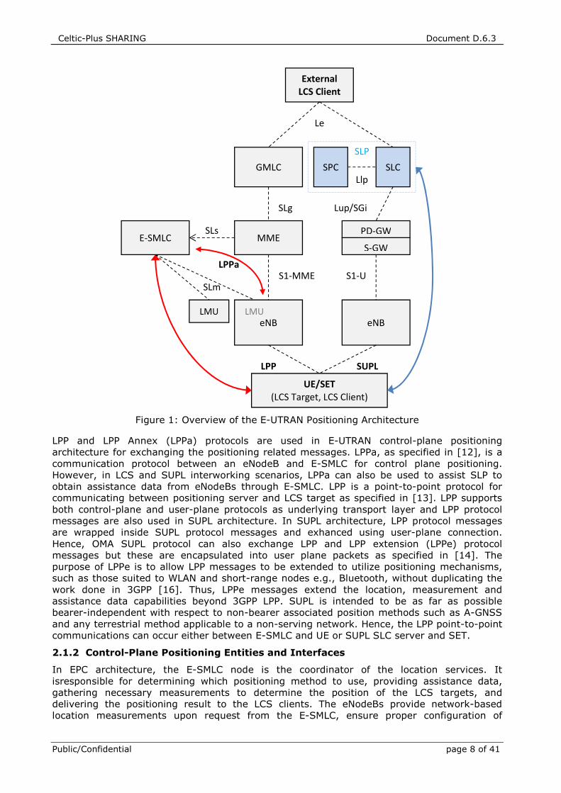
The Evolved Packet Core (EPC) positioning architecture in LTE is illustrated in Figure 1. In the
control-plane solution, the positioning architecture and its functions are distributed across
GMLC, E-SMLC, eNodeBs, Location Measurement Units (LMUs) and UEs [11]. These nodes and
the interfaces are described in more detail in Section 2.1.2. The user-plane solution consists
of SUPL Location Platform (SLP) and the SUPL Enabled Terminal (SET). The positioning
architecture and its functions are distributed across the SUPL Location Centre (SLC) and the
SUPL Positioning Centre (SPC). SUPL nodes and the interfaces are described in Section 2.1.3.
Celtic-Plus SHARING Document D.6.3
Public/Confidential page 8 of 41
Figure 1: Overview of the E-UTRAN Positioning Architecture
LPP and LPP Annex (LPPa) protocols are used in E-UTRAN control-plane positioning
architecture for exchanging the positioning related messages. LPPa, as specified in [12], is a
communication protocol between an eNodeB and E-SMLC for control plane positioning.
However, in LCS and SUPL interworking scenarios, LPPa can also be used to assist SLP to
obtain assistance data from eNodeBs through E-SMLC. LPP is a point-to-point protocol for
communicating between positioning server and LCS target as specified in [13]. LPP supports
both control-plane and user-plane protocols as underlying transport layer and LPP protocol
messages are also used in SUPL architecture. In SUPL architecture, LPP protocol messages
are wrapped inside SUPL protocol messages and exhanced using user-plane connection.
Hence, OMA SUPL protocol can also exchange LPP and LPP extension (LPPe) protocol
messages but these are encapsulated into user plane packets as specified in [14]. The
purpose of LPPe is to allow LPP messages to be extended to utilize positioning mechanisms,
such as those suited to WLAN and short-range nodes e.g., Bluetooth, without duplicating the
work done in 3GPP [16]. Thus, LPPe messages extend the location, measurement and
assistance data capabilities beyond 3GPP LPP. SUPL is intended to be as far as possible
bearer-independent with respect to non-bearer associated position methods such as A-GNSS
and any terrestrial method applicable to a non-serving network. Hence, the LPP point-to-point
communications can occur either between E-SMLC and UE or SUPL SLC server and SET.
2.1.2 Control-Plane Positioning Entities and Interfaces
In EPC architecture, the E-SMLC node is the coordinator of the location services. It
isresponsible for determining which positioning method to use, providing assistance data,
gathering necessary measurements to determine the position of the LCS targets, and
delivering the positioning result to the LCS clients. The eNodeBs provide network-based
location measurements upon request from the E-SMLC, ensure proper configuration of
E-SMLC MME
GMLC
S-GW
PD-GW SLs
SLg
eNB
S1-MME
LPPa
UE/SET (LCS Target, LCS Client)
LPP
Lup/SGi
eNB
S1-U
SUPL
External LCS Client
Le
LMU LMU
SLm
Llp SLC SPC
SLP
Celtic-Plus SHARING Document D.6.3
Public/Confidential 9 (41)
positioning reference signals and configure User Equipment (UE) measurements. LMUs can
make additional location measurements, such as uplink beacons measurements, and
communicate them back to the same E-SMLC that made the request.
In a typical network-triggered LCS situation, the Mobility Management Entity (MME) either
receives a request for location service from another entity such as GMLC or UE, or decides
itself to initiate some location service on behalf of a particular target UE, (e.g., for an IMS
emergency call from the UE). The MME then sends a location service request to an E-SMLC to
process it. This may include transferring assistance data to the target UE to assist location
estimation in case of UE-based or UE-assisted positioning. In UE-based positioning methods,
UE reports its own location estimate, whereas in UE-assisted positioning, it only returns
assistance data such as measurements to help E-SMLC determine the location of target UE. In
uplink based methods, the E-SMLC requests assistance data from LMUs such as
measurements of uplink Sounding Reference Symbols (SRS). The E-SMLC then returns the
result of the location service back to the MME (e.g., a position estimate for the UE and/or an
indication of any assistance data transferred to the UE). In the case that location service was
requested by an entity other than the MME, the E-SMLC returns the location service result to
the corresponding LCS client via MME and GMLC.
2.1.3 User-Plane Positioning Entities and Interfaces
SUPL is the user-plane location technology for positioning mobile devices over wireless
network, based on secure user plane IP tunnels. It is an application layer protocol operating
over the Lup interface between the SUPL Location Platform (SLP) and the SUPL Enabled
Terminal (SET) which has capability of SUPL transactions. The SLP consists of two functional
entities: the SUPL Location Centre (SLC) and the SUPL Positioning Centre (SPC). The SLC is
responsible for coordination and administrative functions in order to provide location services,
while the SPC is responsible for the positioning function. These are architecturally analogous
to the GMLC and the E-SMLC in the control-plane solution. The SLC coordinates the
operations of SUPL in the network and performs the location management functions, including
privacy, initiation, security, roaming, charging, service management, and triggering
positioning calculation. The SPC is responsible for positioning-related functions, including
security, assistance data delivery, reference retrial, and positioning calculation. The SLC and
SPC could be either integrated into a single system, or remain separated. For the separated
mode, the interface between SLC and SPC is the Location Internal Protocol (LIp).
In SUPL architecture, the interface between SET and SLP is Lup which is defined and
standardized by OMA; SUPL is the protocol running over Lup. There are two different
communication modes between SET and SLP: proxy mode and non-proxy mode. For proxy
mode, the SPC system will not have direct communication with the SET. In this environment,
the SLC system will act as a proxy between the SET and the SPC. For non-proxy mode, the
SPC system will have direct communication with the SET. Interworking between the control-
plane LCS architecture and SUPL release 2.0 can exist as described in [11]. If the E-SMLC has
an interface to SPC function as defined in OMA SUPL release 2.0 ([14], [15]), it can provide a
consistent set of positioning methods for deployments utilizing both control-plane and user-
plane. This interworking does enable the SPC to retrieve measurements from eNodeB.
However, the interworking does not enable the use of user-plane signalling for part of a
control-plane positioning session.
2.1.4 Positioning methods
Besides control and user-plane positioning architectures, 3GPP networks support also a wide
range of complementary positioning methods. Basic positioning method is CID that utilizes
cellular system knowledge about the geographical location of the UE’s serving cell. CID
method has been mandatory in LTE since Release 8. Other methods such as Enhanced CID
(E-CID), Observed Time Difference of Arrival (OTDOA), Uplink Time Difference of Arrival
(UTDOA) and Assisted Global Navigation Satellite System (A-GNSS) methods were made
available in later releases. In addition to the standardized positioning methods, several other
methods are available via SUPL that do not need be standardized such as RF fingerprinting or
Celtic-Plus SHARING Document D.6.3
Public/Confidential page 10 of 41
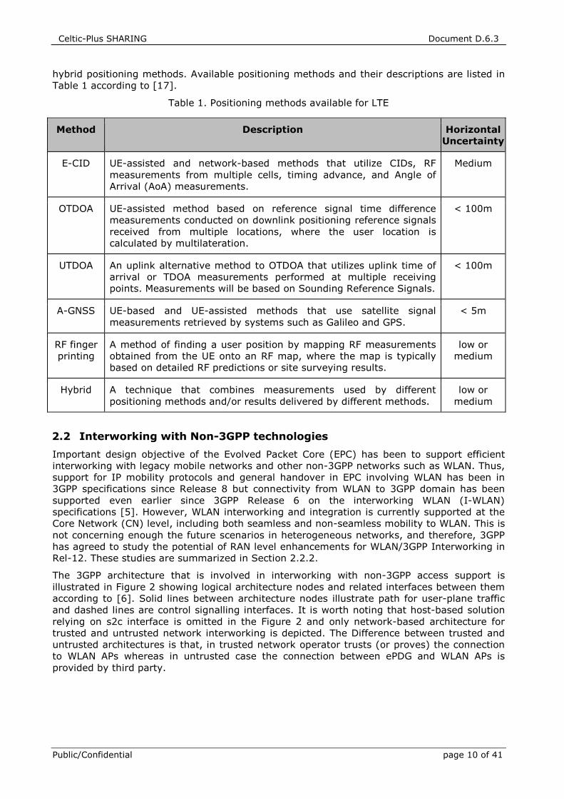
hybrid positioning methods. Available positioning methods and their descriptions are listed in
Table 1 according to [17].
Table 1. Positioning methods available for LTE
Method Description Horizontal Uncertainty
E-CID UE-assisted and network-based methods that utilize CIDs, RF
measurements from multiple cells, timing advance, and Angle of
Arrival (AoA) measurements.
Medium
OTDOA UE-assisted method based on reference signal time difference
measurements conducted on downlink positioning reference signals
received from multiple locations, where the user location is
calculated by multilateration.
< 100m
UTDOA An uplink alternative method to OTDOA that utilizes uplink time of
arrival or TDOA measurements performed at multiple receiving
points. Measurements will be based on Sounding Reference Signals.
< 100m
A-GNSS UE-based and UE-assisted methods that use satellite signal
measurements retrieved by systems such as Galileo and GPS.
< 5m
RF finger
printing
A method of finding a user position by mapping RF measurements
obtained from the UE onto an RF map, where the map is typically
based on detailed RF predictions or site surveying results.
low or
medium
Hybrid A technique that combines measurements used by different
positioning methods and/or results delivered by different methods.
low or
medium
2.2 Interworking with Non-3GPP technologies
Important design objective of the Evolved Packet Core (EPC) has been to support efficient
interworking with legacy mobile networks and other non-3GPP networks such as WLAN. Thus,
support for IP mobility protocols and general handover in EPC involving WLAN has been in
3GPP specifications since Release 8 but connectivity from WLAN to 3GPP domain has been
supported even earlier since 3GPP Release 6 on the interworking WLAN (I-WLAN)
specifications [5]. However, WLAN interworking and integration is currently supported at the
Core Network (CN) level, including both seamless and non-seamless mobility to WLAN. This is
not concerning enough the future scenarios in heterogeneous networks, and therefore, 3GPP
has agreed to study the potential of RAN level enhancements for WLAN/3GPP Interworking in
Rel-12. These studies are summarized in Section 2.2.2.
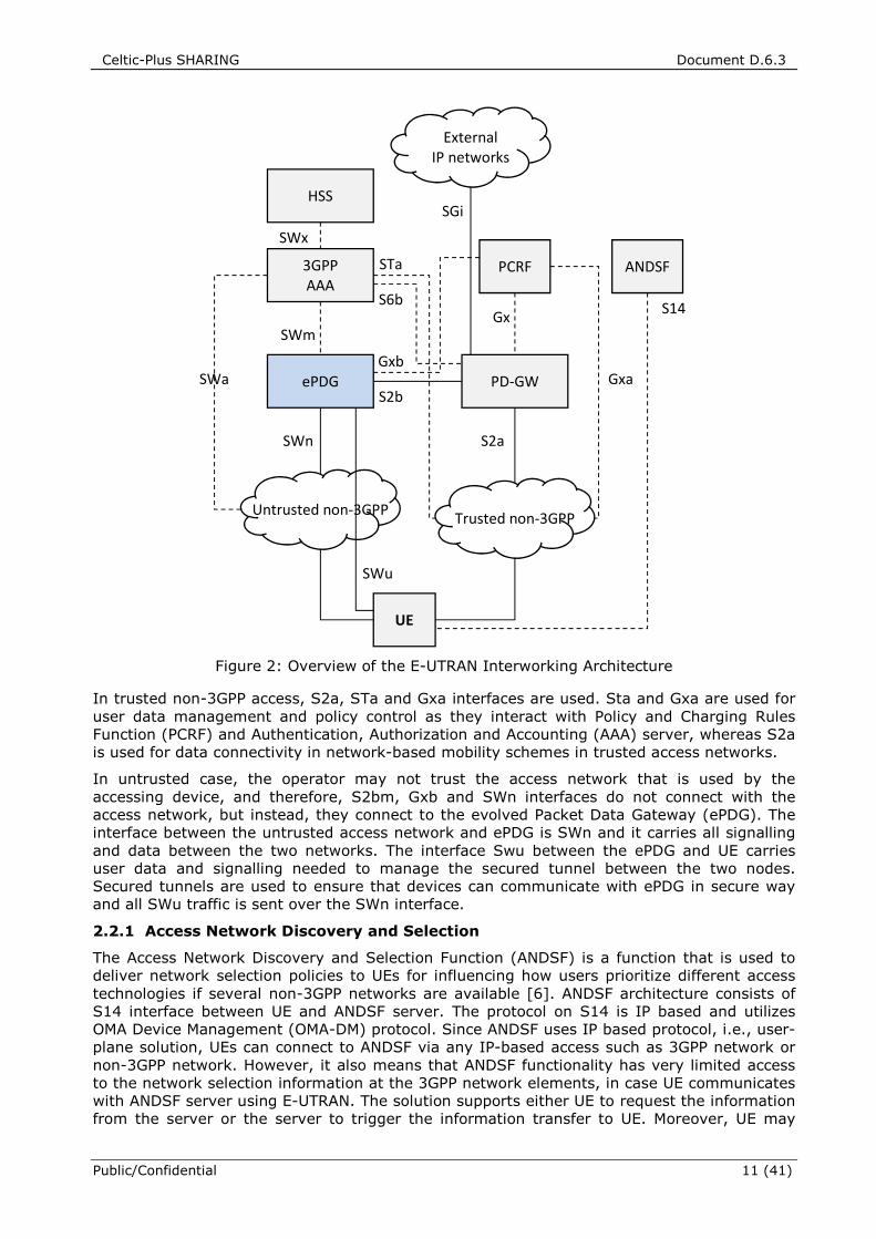
The 3GPP architecture that is involved in interworking with non-3GPP access support is
illustrated in Figure 2 showing logical architecture nodes and related interfaces between them
according to [6]. Solid lines between architecture nodes illustrate path for user-plane traffic
and dashed lines are control signalling interfaces. It is worth noting that host-based solution
relying on s2c interface is omitted in the Figure 2 and only network-based architecture for
trusted and untrusted network interworking is depicted. The Difference between trusted and
untrusted architectures is that, in trusted network operator trusts (or proves) the connection
to WLAN APs whereas in untrusted case the connection between ePDG and WLAN APs is
provided by third party.
Celtic-Plus SHARING Document D.6.3
Public/Confidential 11 (41)
Figure 2: Overview of the E-UTRAN Interworking Architecture
In trusted non-3GPP access, S2a, STa and Gxa interfaces are used. Sta and Gxa are used for
user data management and policy control as they interact with Policy and Charging Rules
Function (PCRF) and Authentication, Authorization and Accounting (AAA) server, whereas S2a
is used for data connectivity in network-based mobility schemes in trusted access networks.
In untrusted case, the operator may not trust the access network that is used by the
accessing device, and therefore, S2bm, Gxb and SWn interfaces do not connect with the
access network, but instead, they connect to the evolved Packet Data Gateway (ePDG). The
interface between the untrusted access network and ePDG is SWn and it carries all signalling
and data between the two networks. The interface Swu between the ePDG and UE carries
user data and signalling needed to manage the secured tunnel between the two nodes.
Secured tunnels are used to ensure that devices can communicate with ePDG in secure way
and all SWu traffic is sent over the SWn interface.
2.2.1 Access Network Discovery and Selection
The Access Network Discovery and Selection Function (ANDSF) is a function that is used to
deliver network selection policies to UEs for influencing how users prioritize different access
technologies if several non-3GPP networks are available [6]. ANDSF architecture consists of
S14 interface between UE and ANDSF server. The protocol on S14 is IP based and utilizes
OMA Device Management (OMA-DM) protocol. Since ANDSF uses IP based protocol, i.e., user-
plane solution, UEs can connect to ANDSF via any IP-based access such as 3GPP network or
non-3GPP network. However, it also means that ANDSF functionality has very limited access
to the network selection information at the 3GPP network elements, in case UE communicates
with ANDSF server using E-UTRAN. The solution supports either UE to request the information
from the server or the server to trigger the information transfer to UE. Moreover, UE may
S14
HSS
PCRF 3GPP AAA
PD-GW
SWm
UE
S2a
SGi
SWx
S6b
ePDG SWa
SWn
S2b
SWu
Gx
Gxa
STa ANDSF
Untrusted non-3GPP Trusted non-3GPP
External IP networks
Gxb
Celtic-Plus SHARING Document D.6.3
Public/Confidential page 12 of 41
provide some information such as GPS coordinates or cell identities of nearby radio base
stations, to the ANDSF server to assist in the generation of the access selection information.
However, ANDSF is not intended to be used as a very dynamic mechanism for controlling
access selection in real time.
The ANDSF can provide three types of information to UE such as Access Network Discovery
and Selection information, Inter-System Mobility Policies, and Inter-System Routing Policies.
The Access Network Discovery information includes list of access networks (3GPP and non-
3GPP) available for the UE. This can help the UE in discovering networks and speeding up the
needed scanning.
2.2.2 LTE/WLAN Offloading in LTE Release 12
In 3GPP Release 10, the support for simultaneous multi-access was introduced where UE can
connect to 3GPP and non-3GPP networks simultaneously to better support the data offloading
to WLAN. Moreover, in 3GPP Release 11, trusted non-3GPP concept was extended specifically
to better support WLAN connectivity. However, even tighter coordination between 3GPP radio
access network and WLAN access network was seen needed and therefore 3GPP has agreed
to study potential RAN level enhancements for WLAN/3GPP interworking in Release 12. The
results of these studies are collected into [4]. RAN level enhancements for interworking are
seen necessary because operator-deployed WLAN networks are still often under-utilized. The
goal of Release 12 interworking study was to identify solutions that allow enhanced operator
control for WLAN interworking and enable WLAN to be included in the operator’s cellular Radio
Resource Management (RRM). Specifically, enhancements for access network selection and
mobility that were seen important are those that can take into account information such as
radio link quality per UE, backhaul capability and loading for both cellular and WLAN access
methods.
The solutions should provide improved bi-directional load balancing between WLAN and 3GPP
radio access networks and therefore provide improved system capacity and improve the
utilization of WLAN. Moreover, solutions should be compatible with the existing CN WLAN
related functionality and be backward compatible with existing 3GPP and WLAN specifications
thereby avoiding changes to IEEE and WiFi Alliance specifications. In addition, solutions
should reduce or maintain battery consumption which may be due to WLAN scanning. In a
typical use case scenario, there can be several WLAN APs within the coverage of a single
UTRAN/E-UTRAN cell and the eNB/RNC may know the location of the WLAN AP among other
WLAN AP parameters such as its identifier. However scenarios where such information is not
available should be supported as well. Currently, there is no RAN-level information exchange
between eNBs/RNCs and APs via standardized interfaces. However, some information may be
exchanged via O&M. At the very beginning of the Release 12 interworking study, three
alternative solution candidates were proposed.
In solution 1, RAN provides RAN assistance information such as E-UTRAN signal strength and
quality thresholds, WLAN received signal strength indication (RSSI) threshold and list of
target WLAN access nodes, to the UE through broadcast signalling (and optionally dedicated
signalling). The UE uses RAN assistance information, UE measurements, information provided
by WLAN, and policies that are obtained via the ANDSF, via existing OMA-DM mechanisms or
pre-configured at the UE, to steer traffic to WLAN or to RAN. The main purpose is to enable
dynamic update procedure for ANDSF Management Object (ANDSF-MO) thresholds. In
solution 2, the offloading rules are specified in RAN specifications. The RAN provides (through
dedicated and/or broadcast signalling) thresholds which are used in the rules. The main
difference between solution 1 and solution 2 is that, solution 2 does not require
implementation of ANDSF functionality, and the rules specified in RAN specifications can have
higher priority than rules specified in ANDSF MO.
In solution 3, traffic steering for UEs that have established RRC connection is controlled by
the network using dedicated traffic steering commands, potentially based also on WLAN
measurements (reported by the UE). For UEs in IDLE mode the solution is similar to solution
1 or 2. In addition, UEs can be configured to connect to RAN first and wait for the dedicated
traffic steering commands. Solution 3 consists of three steps. First, UE is configured to do
Celtic-Plus SHARING Document D.6.3
Public/Confidential 13 (41)
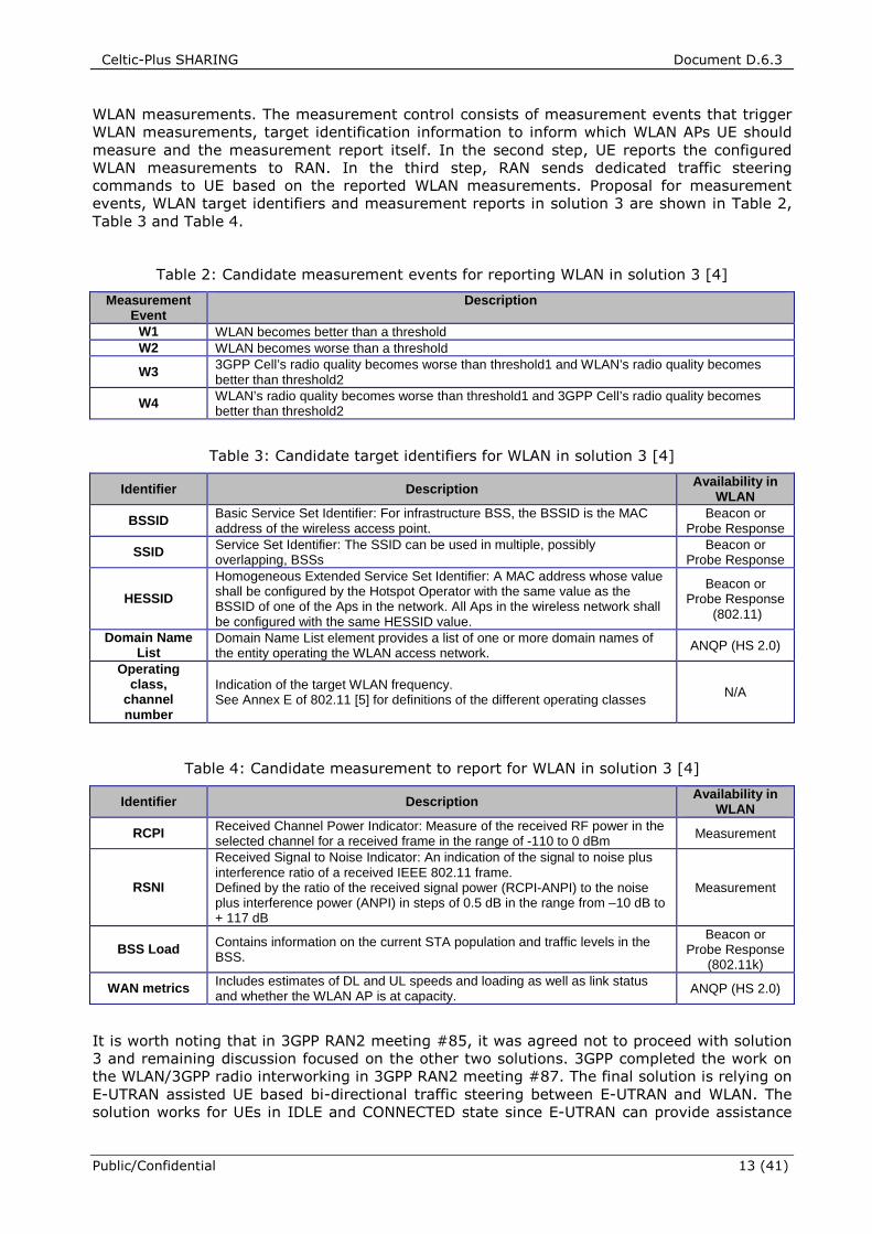
WLAN measurements. The measurement control consists of measurement events that trigger
WLAN measurements, target identification information to inform which WLAN APs UE should
measure and the measurement report itself. In the second step, UE reports the configured
WLAN measurements to RAN. In the third step, RAN sends dedicated traffic steering
commands to UE based on the reported WLAN measurements. Proposal for measurement
events, WLAN target identifiers and measurement reports in solution 3 are shown in Table 2,
Table 3 and Table 4.
Table 2: Candidate measurement events for reporting WLAN in solution 3 [4]
Measurement Event
Description
W1 WLAN becomes better than a threshold W2 WLAN becomes worse than a threshold
W3 3GPP Cell’s radio quality becomes worse than threshold1 and WLAN’s radio quality becomes better than threshold2
W4 WLAN’s radio quality becomes worse than threshold1 and 3GPP Cell’s radio quality becomes better than threshold2
Table 3: Candidate target identifiers for WLAN in solution 3 [4]
Identifier Description Availability in WLAN
BSSID Basic Service Set Identifier: For infrastructure BSS, the BSSID is the MAC address of the wireless access point.
Beacon or Probe Response
SSID Service Set Identifier: The SSID can be used in multiple, possibly overlapping, BSSs
Beacon or Probe Response
HESSID
Homogeneous Extended Service Set Identifier: A MAC address whose value shall be configured by the Hotspot Operator with the same value as the BSSID of one of the Aps in the network. All Aps in the wireless network shall be configured with the same HESSID value.
Beacon or Probe Response
(802.11)
Domain Name List
Domain Name List element provides a list of one or more domain names of the entity operating the WLAN access network. ANQP (HS 2.0)
Operating class,
channel number
Indication of the target WLAN frequency. See Annex E of 802.11 [5] for definitions of the different operating classes N/A
Table 4: Candidate measurement to report for WLAN in solution 3 [4]
Identifier Description Availability in WLAN
RCPI Received Channel Power Indicator: Measure of the received RF power in the selected channel for a received frame in the range of -110 to 0 dBm Measurement
RSNI
Received Signal to Noise Indicator: An indication of the signal to noise plus interference ratio of a received IEEE 802.11 frame. Defined by the ratio of the received signal power (RCPI-ANPI) to the noise plus interference power (ANPI) in steps of 0.5 dB in the range from –10 dB to + 117 dB
Measurement
BSS Load Contains information on the current STA population and traffic levels in the BSS.
Beacon or Probe Response
(802.11k)
WAN metrics Includes estimates of DL and UL speeds and loading as well as link status and whether the WLAN AP is at capacity. ANQP (HS 2.0)
It is worth noting that in 3GPP RAN2 meeting #85, it was agreed not to proceed with solution
3 and remaining discussion focused on the other two solutions. 3GPP completed the work on
the WLAN/3GPP radio interworking in 3GPP RAN2 meeting #87. The final solution is relying on
E-UTRAN assisted UE based bi-directional traffic steering between E-UTRAN and WLAN. The
solution works for UEs in IDLE and CONNECTED state since E-UTRAN can provide assistance
Celtic-Plus SHARING Document D.6.3
Public/Confidential page 14 of 41
parameters to UEs via broadcast and dedicated signalling using System Information Block
(SIB) 17. The UE uses the RAN assistance parameters in the selection of access network and
for traffic steering between E-UTRAN and WLAN as specified in TS 23.402 [6]. If UE is
configured with ANDSF policies, it forwards the received RAN assistance parameters to upper
layers. Otherwise the UE shall use them in the access network selection and traffic steering
using the rules as defined in TS 36.304 [19]. However, the access network selection and
traffic steering rules defined in TS 36.304 are only applied to the WLANs whose identifiers are
provided by the E-UTRAN.
The RAN assistance parameters may include E-UTRAN signal strength and quality thresholds,
WLAN channel utilization thresholds, WLAN backhaul data rate thresholds, WLAN received
signal strength indication (RSSI) threshold measured from beacon frames and Offload
Preference Indicator. Network can also signal a list of WLAN identifiers to the UEs via
broadcast signalling. The UE in CONNECTED state shall apply the parameters obtained via
dedicated signalling if such parameters have been received from the serving cell. Otherwise,
the UE shall apply the parameters obtained via broadcast signalling. Moreover, in case of RAN
sharing, each network sharing the RAN can provide independent sets of RAN assistance
parameters. It is worth noting that it is not specified how E-UTRAN collects and maintains the
list of target identifiers. The proposed GMDT described in Chapter 4 describes one
straightforward way to automate the collection of target WLAN identifiers together with MDT
measurements.
Celtic-Plus SHARING Document D.6.3
Public/Confidential 15 (41)
3 MINIMIZATION OF DRIVE TESTS
This chapter introduces a SON related topic called minimization of drive tests, whose target is
to reduce the required efforts to carry out drive tests in deployed radio networks. The enabler
behind minimization of drive tests is the operator’s capability to request user equipment (UE)
to make measurements and report them back to the network with location information.
Therefore, no dedicated drive tests are necessarily needed given that there are enough UEs to
cover the desired areas moving around in the network. Although SON and MDT are clearly
related, the solutions for MDT are able to work independently from SON support in the
network [20].
MDT use cases for self-organizing networks were introduced by the operators alliance Next
Generation Mobile Networks (NGMN) during 2008 [22] and since then, the MDT concept has
been studied by the network vendors and operators in 3GPP [3], [23]. The aim of the MDT
research in 3GPP has been to define a set of measurements, measurement reporting
principles and procedures, which would help to collect coverage related information from UEs.
MDT feasibility study phase [3] started at late 2009 and during 2010 it focused on defining
the reported measurement entities and MDT use cases such as coverage optimization and
quality of service verification. Coverage optimization use case targets the detection of
network problems such as coverage holes, weak coverage, pilot pollution, overshoot
coverage, and issues with uplink coverage [3]. After the feasibility study, the research
focused on defining MDT measurement, reporting and configuration schemes for LTE release
10 during 2011 [23]. Later, the focus of MDT work has been on enhancements in the
availability of the detailed location information and improvements in QoS verification [24]. In
Release 11, several new features were added to MDT such as downlink and uplink throughput
measurements and traffic volume measurement, which increase the usability of MDT [25].
After all, the traffic profile of a UE has great impact on the radio interface behavior
(Transmission Time Interval (TTI) and resource block allocation etc.). A support for data
volume measurement is also added for detecting traffic hotspots and helping the planning of
possible capacity extensions. Moreover, Release 11 brings improvements to radio link failure
and RRC connection failure reporting [25]. In addition, there are several applications in which
drive tests are helpful and thus MDT can also be applied. For example, in this deliverable the
focus is on hybrid localization which becomes possible due to extensive measurement
databases that MDT can provide. Other MDT use cases, in addition to those already
mentioned, include at least faster deployment of new base stations, learning based mobility
optimization, capacity optimization and parametrization for control channels.
3.1.1 Architecture
Minimization of drive tests feature was specified in 3GPP Release 10 for centralized collection
of UE and radio access network (RAN) measurements associated with location information.
The overall MDT functionality is described in [20]. For an easy-to-read overall description
about the MDT architecture, reader may also refer to [26], [25]. MDT functionality uses the
User and Equipment Trace framework [27], allowing operations & maintenance subsystem to
record RRC signaling messages between UE and RAN nodes. In order to guarantee the
visibility of MDT measurement results in the eNodeB, the control plane architecture for MDT
signaling was selected. The MDT specification identifies the following entities involved in MDT
process: O&M system which controls MDT data collection, trace element (TCE) where MDT
trace records are forwarded for post processing the data, UEs from which the data is collected
and RAN nodes. Element manager (EM) located in operator’s O&M system is needed for
activating the tracing and providing the MDT configuration. MDT measurement is always a
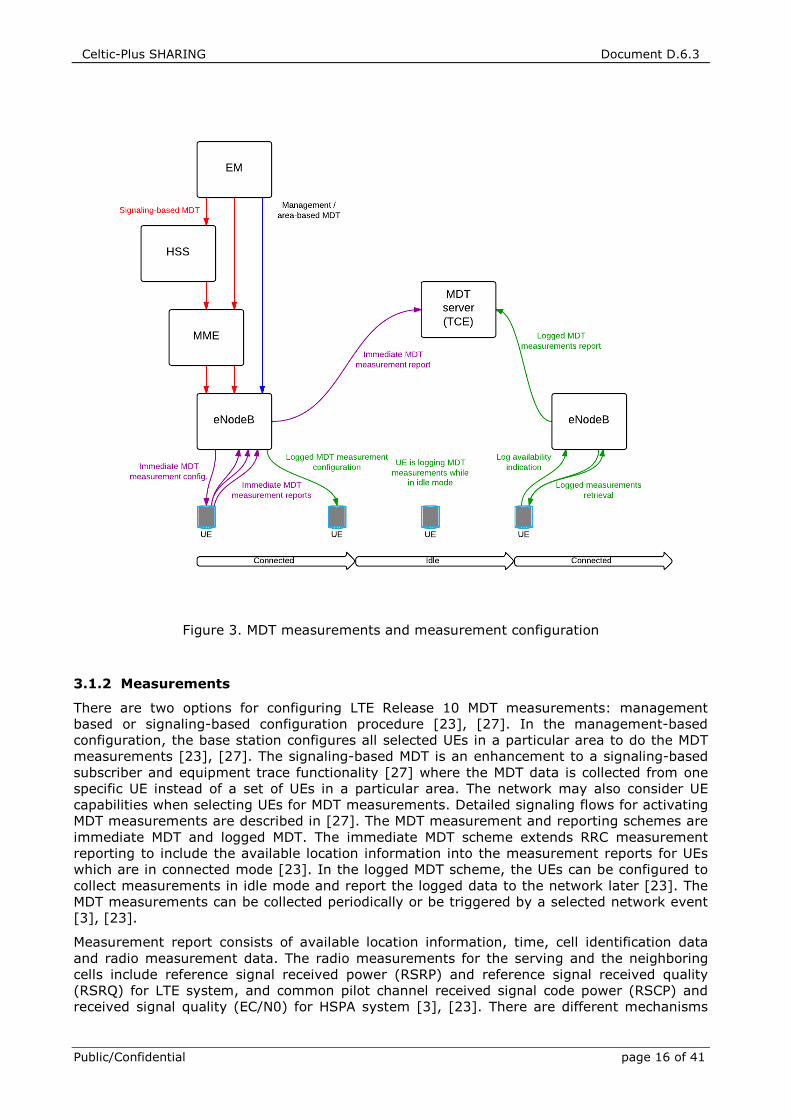
network initiated process. Figure 3 visualizes the MDT architecture showing also the MDT
signaling, as UE moves from connected mode to idle mode and back.
Celtic-Plus SHARING Document D.6.3
Public/Confidential page 16 of 41
Figure 3. MDT measurements and measurement configuration
3.1.2 Measurements
There are two options for configuring LTE Release 10 MDT measurements: management
based or signaling-based configuration procedure [23], [27]. In the management-based
configuration, the base station configures all selected UEs in a particular area to do the MDT
measurements [23], [27]. The signaling-based MDT is an enhancement to a signaling-based
subscriber and equipment trace functionality [27] where the MDT data is collected from one
specific UE instead of a set of UEs in a particular area. The network may also consider UE
capabilities when selecting UEs for MDT measurements. Detailed signaling flows for activating
MDT measurements are described in [27]. The MDT measurement and reporting schemes are
immediate MDT and logged MDT. The immediate MDT scheme extends RRC measurement
reporting to include the available location information into the measurement reports for UEs
which are in connected mode [23]. In the logged MDT scheme, the UEs can be configured to
collect measurements in idle mode and report the logged data to the network later [23]. The
MDT measurements can be collected periodically or be triggered by a selected network event
[3], [23].
Measurement report consists of available location information, time, cell identification data
and radio measurement data. The radio measurements for the serving and the neighboring
cells include reference signal received power (RSRP) and reference signal received quality
(RSRQ) for LTE system, and common pilot channel received signal code power (RSCP) and
received signal quality (EC/N0) for HSPA system [3], [23]. There are different mechanisms
Celtic-Plus SHARING Document D.6.3
Public/Confidential 17 (41)
for the estimation of user location. The availability of location information also depends on the
UE implementation [20]. The coarsest location estimation is the serving cell global
identification (CGI) and in the best case the detailed location estimate is obtained from the
Global Navigation Satellite System (GNSS). The cell identification information consists of the
serving cell CGI or physical cell identifications (PCI) of the detected neighboring cells. UE
power constraints may also limit the availability of different positioning methods [20].
3.1.3 Measurement Trace Activation
Before the MDT tracing can be started, a base station – E-UTRAN NodeB (eNB) – is activated
and configured to collect MDT measurements. In step 1, EM sends a cell trace session
activation request to the eNB including MDT trace configuration. The trace configuration
consists of trace parameters such as trace job type, trace reference (TR) and TCE address, so
that the eNB can later report the trace records back to the trace element. Trace reference is a
globally unique reference for identifying the trace session [27]. TCE address defines the IP
(Internet Protocol) address of the trace collection entity [27]. After cell traffic trace activation,
the eNB selects the UEs for MDT while taking into account the user consent such as user’s
permission for an operator to collect the MDT measurements. The eNB sends the RRC
measurement configurations to the selected UEs. This includes reporting triggers, intervals
and list of intra-frequency, inter-frequency and inter-RAT measurements from 2G and 3G
networks with a requirement that UEs include the available location information into the
measurement reports as specified in the RRC specification information element (IE)
ReportConfigEUTRA field [28]. Currently available triggers for reporting network events are
listed in Table 5. When the RRC measurement condition is fulfilled e.g., a periodical timer
expires or a certain network event occurs, the UE sends available RSRP and RSRQ
measurements to the eNB with the available LocationInfo IE added to the measurement
report [28].
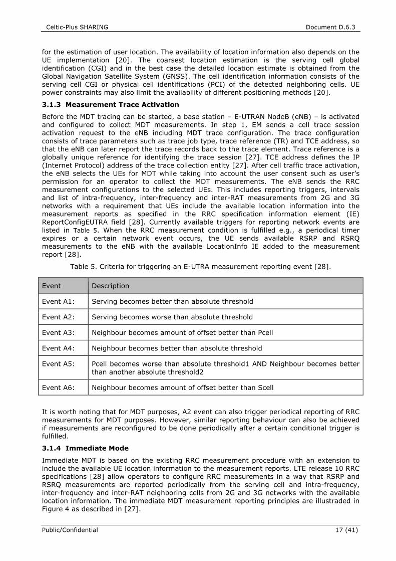
Table 5. Criteria for triggering an E‑UTRA measurement reporting event [28].
Event Description
Event A1: Serving becomes better than absolute threshold
Event A2: Serving becomes worse than absolute threshold
Event A3: Neighbour becomes amount of offset better than Pcell
Event A4: Neighbour becomes better than absolute threshold
Event A5: Pcell becomes worse than absolute threshold1 AND Neighbour becomes better
than another absolute threshold2
Event A6: Neighbour becomes amount of offset better than Scell
It is worth noting that for MDT purposes, A2 event can also trigger periodical reporting of RRC
measurements for MDT purposes. However, similar reporting behaviour can also be achieved
if measurements are reconfigured to be done periodically after a certain conditional trigger is
fulfilled.
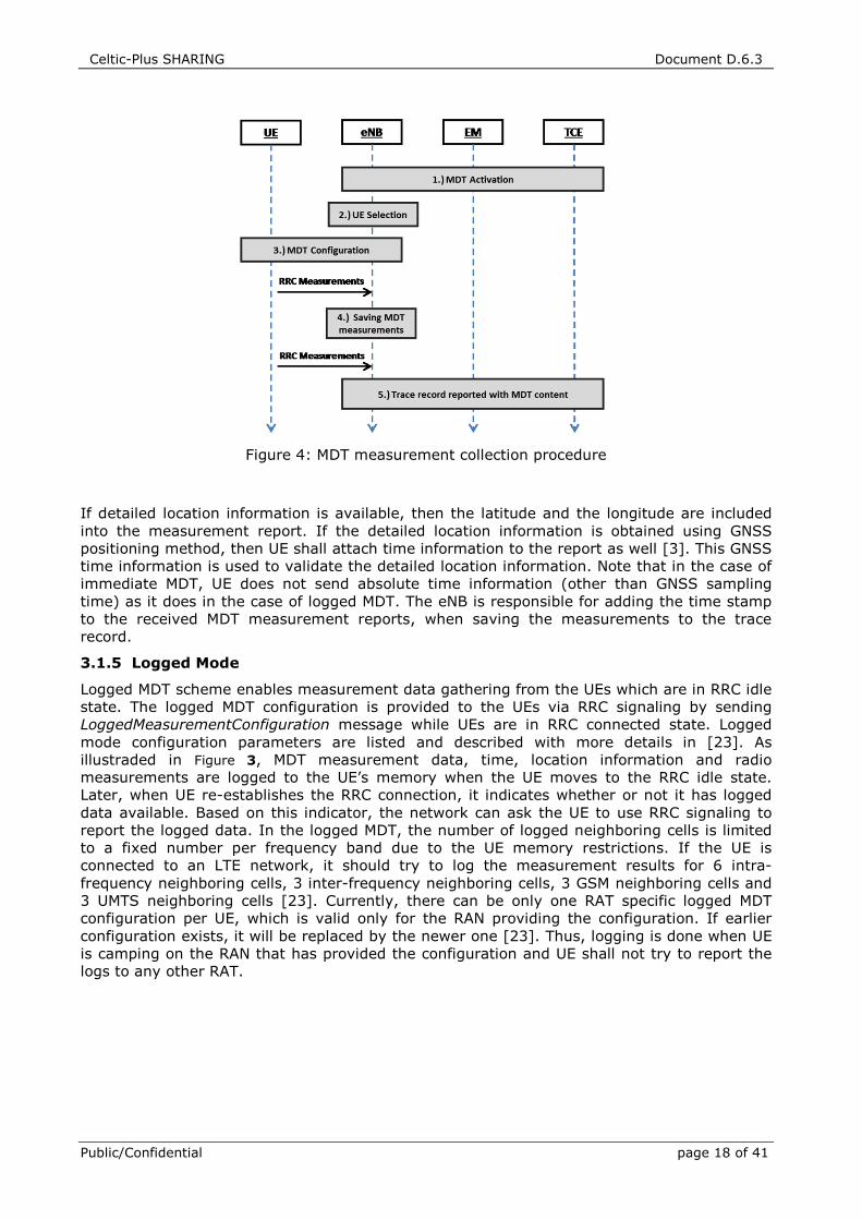
3.1.4 Immediate Mode
Immediate MDT is based on the existing RRC measurement procedure with an extension to
include the available UE location information to the measurement reports. LTE release 10 RRC
specifications [28] allow operators to configure RRC measurements in a way that RSRP and
RSRQ measurements are reported periodically from the serving cell and intra-frequency,
inter-frequency and inter-RAT neighboring cells from 2G and 3G networks with the available
location information. The immediate MDT measurement reporting principles are illustraded in
Figure 4 as described in [27].
Celtic-Plus SHARING Document D.6.3
Public/Confidential page 18 of 41
Figure 4: MDT measurement collection procedure
If detailed location information is available, then the latitude and the longitude are included
into the measurement report. If the detailed location information is obtained using GNSS
positioning method, then UE shall attach time information to the report as well [3]. This GNSS
time information is used to validate the detailed location information. Note that in the case of
immediate MDT, UE does not send absolute time information (other than GNSS sampling
time) as it does in the case of logged MDT. The eNB is responsible for adding the time stamp
to the received MDT measurement reports, when saving the measurements to the trace
record.
3.1.5 Logged Mode
Logged MDT scheme enables measurement data gathering from the UEs which are in RRC idle
state. The logged MDT configuration is provided to the UEs via RRC signaling by sending
LoggedMeasurementConfiguration message while UEs are in RRC connected state. Logged
mode configuration parameters are listed and described with more details in [23]. As
illustraded in Figure 3, MDT measurement data, time, location information and radio
measurements are logged to the UE’s memory when the UE moves to the RRC idle state.
Later, when UE re-establishes the RRC connection, it indicates whether or not it has logged
data available. Based on this indicator, the network can ask the UE to use RRC signaling to
report the logged data. In the logged MDT, the number of logged neighboring cells is limited
to a fixed number per frequency band due to the UE memory restrictions. If the UE is
connected to an LTE network, it should try to log the measurement results for 6 intra-
frequency neighboring cells, 3 inter-frequency neighboring cells, 3 GSM neighboring cells and
3 UMTS neighboring cells [23]. Currently, there can be only one RAT specific logged MDT
configuration per UE, which is valid only for the RAN providing the configuration. If earlier
configuration exists, it will be replaced by the newer one [23]. Thus, logging is done when UE
is camping on the RAN that has provided the configuration and UE shall not try to report the
logs to any other RAT.
Celtic-Plus SHARING Document D.6.3
Public/Confidential 19 (41)
4 ENHANCEMENT TO 3GPP MDT ARCHITECTURE
This section describes a proposal to enhance 3GPP MDT functionality to support collection and
correlation of WLAN coverage measurements with MDT measurements. The proposed
architecture consists of two alternative designs: user-plane architecture and control-plane
architectures for generic MDT.
4.1 Generalized MDT Measurement Architecture
Based on the requirements identified by use case scenarios in SHARING work package 2 and
the results of the studies addressing the localization challenges in HetNet infrastructures
(e.g., femtocells and WLAN), a generic measurement architecture is designed. The proposed
architecture target is to automate the collection of UE WLAN radio measurements and
minimizing the need of manual drive-tests in heterogeneous small cell networks consisting of
LTE and WLAN access nodes. We call this architecture generalized MDT (GMDT). The simple
idea of GMDT is that additional measurement results about WLAN APs could be added to the
MDT reports containing E-UTRAN and UTRAN network measurements in addition to UE
location. Such added information can be very useful for improving RF fingerprint positioning
accuracy, building WLAN coverage maps, and improving small cell discovery. It can also be
used for ANDSF database and policy management. Thus the benefits of GMDT are visible to
operators and end users, for example, in more accurate indoor positioning or more efficient
WLAN offloading.
This chapter describes the appropriate architecture changes and identifies the localization
functional blocks and logical interfaces as well as the information exchanged through them.
The proposed architecture is aligned as much as possible with 3GPP Study Item on
WLAN/3GPP radio interworking [4] for measurements and triggering events. It also relates to
the usability of the GMDT as a potential enabler of self-organizing WLAN networks. The
importance of GMDT increases as operators accelerate the deployments of WLAN networks.
This is expected to happen due to the fact that even though 3GPP technology is constantly
developing, it is not necessarily enough for carrying the ever expanding amount of mobile
data [1] generated on certain hot spot areas. On the other hand, the capacity of operator’s
cellular networks is restricted by the available frequency bands, which makes it tempting for
mobile operators to exploit also the unlicensed ISM (Industrial, Scientific and Medical) bands.
Therefore, the importance of the generalized MDT seems to increase during the next five
years and it will play an important role in facilitating the multi-layer, multi-RAT heterogeneous
networks interworking.
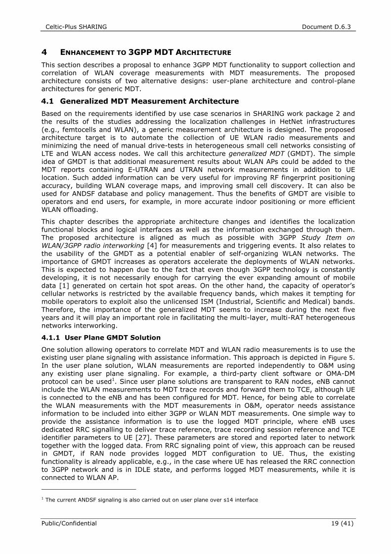
4.1.1 User Plane GMDT Solution
One solution allowing operators to correlate MDT and WLAN radio measurements is to use the
existing user plane signaling with assistance information. This approach is depicted in Figure 5.
In the user plane solution, WLAN measurements are reported independently to O&M using
any existing user plane signaling. For example, a third-party client software or OMA-DM
protocol can be used1. Since user plane solutions are transparent to RAN nodes, eNB cannot
include the WLAN measurements to MDT trace records and forward them to TCE, although UE
is connected to the eNB and has been configured for MDT. Hence, for being able to correlate
the WLAN measurements with the MDT measurements in O&M, operator needs assistance
information to be included into either 3GPP or WLAN MDT measurements. One simple way to
provide the assistance information is to use the logged MDT principle, where eNB uses
dedicated RRC signalling to deliver trace reference, trace recording session reference and TCE
identifier parameters to UE [27]. These parameters are stored and reported later to network
together with the logged data. From RRC signaling point of view, this approach can be reused
in GMDT, if RAN node provides logged MDT configuration to UE. Thus, the existing
functionality is already applicable, e.g., in the case where UE has released the RRC connection
to 3GPP network and is in IDLE state, and performs logged MDT measurements, while it is
connected to WLAN AP.
1 The current ANDSF signaling is also carried out on user plane over s14 interface
Celtic-Plus SHARING Document D.6.3
Public/Confidential page 20 of 41
Figure 5. User plane architecture for GMDT.
For user-plane GMDT solution, we propose to report at least the following WLAN
measurements, when available:
• Sequence of the WLAN measurements
• Trace assistance information
• Time stamp
Moreover, the sequence of the WLAN measurements consists of:
• Received Signal Strength Indicator (RSSI) measured from beacon frames ( 1 Byte)
• Basic Service Set Identifier (32 Bytes)
• Service Set Identifier (6 Bytes)
• Homogenous Extended Service Set Identifier (6 Bytes)
If UE is configured to report WLAN measurements using any user plane protocol, then
correlation between MDT trace records and GMDT WLAN measurements can be done in O&M
by using the trace assistance information incorporated in the WLAN measurements. The
prospects of using the user plane solution for correlating MDT and WLAN measurements is
that, it does not require changes to the RRC signaling over the Uu interface. All needed
assistance information can be conveyed to UE, by either configuring logged MDT
measurements properly in RAN nodes or conveying trace assistance information through user
plane. If logged and immediate MDT measurements are configured simultaneously, currently
only logged MDT trace assistance information is signalled to UE. Since trace parameters (TR
and TRSR) are different for logged and immeadiate MDT measurements, RAN would have to
ensure that both trace records can be correlated later. This would ensure that trace
assistance information is available and can be used by the user plane GMDT application.
Moreover, if different dedicated applications are used for MDT measurements and WLAN
measurements, more information can be collected. A dedicated application tailored for the
needs of WLAN operator is likely to report much more measurement information about the
WLAN APs than what would be feasible to include in the 3GPP MDT trace records. The main
constraint of using the user plane solution with trace assistance information is the fact that it
Celtic-Plus SHARING Document D.6.3
Public/Confidential 21 (41)
requires software updates to the UE modem firmware and to user plane measurement
application for making the trace assistance information available on upper application layers.
On the other hand, trace assistance information alone is not sensitive information from
operator or user privacy perspecitve so there is no strong argumentation not to do so. In
addition, new O&M signalling is needed between RAN and GMDT server for fetching the
measurement data. GMDT server can be part of the O&M or WLAN Network Management
System (NMS) and interface for exchanging measurement data does not exist at the moment.
However, building such support using existing protocols and interfaces should be possible with
small effort. It is worth noting that GMDT server cannot acquire the routing data based on the
trace assistance information without coordinating with RAN nodes for decoding the location
and IP address of TCE based on TCE ID. Another minor constraint is the configurability of the
measurements. Just by making available the trace assistance information, the correlation
between the MDT and WLAN measurements can be ensured. However, little can be done for
configuring which WLAN APs are measured with the MDT trace assistance information. Hence,
for enhancing the user plane solution, more coordination between the 3GPP and WLAN NMS is
needed. One way of providing such coordination is to rely on Release-12 LTE/WLAN
interworking solution that allows providing candidate WLAN AP identifiers to UE either through
RRC signalling or via ANDSF functionality.
4.1.2 Control Plane GMDT Solution
The control plane solution of GMDT employs the same network elements as Release 10 MDT
architecture but small modifications to measurements and signaling are needed. The main
difference is that in GMDT, UE measures WLAN APs and includes the measurements either to
RRC measurement signaling or Logged MDT signaling. Hence, both logged and immediate
GMDT reporting modes are available and there are no differences in that sense comparing to
the current MDT specification. The content of proposed GMDT measurements and triggering
network events are aligned with the access network selection and traffic steering solution 3
described in Section 2.2.2. In this solution, UEs in IDLE and CONNECTED state are controlled
by eNB using either dedicated or broadcast signaling, potentially based also on WLAN
measurements reported by the UE. In order to do WLAN measurements, the RAN node will
have to configure them. In the proposed architecture, this would be carried out by
transmitting target WLAN identifiers to UE. These indetifiers specify the identity of WLAN APs
to be measured, as well as, the related parameters such as the operating channels to be
searched for [4]. It should be noted that only the access points owned by operator or its
partner are to be configured for measurements. The proposed target identifier fields to be
signaled are shown in Table 3. As described in section 3.1.3, the information element
ReportConfigEUTRA specifies criteria for triggering of an E‑UTRA measurement reporting
event for MDT.
It is anticipated that if eNB uses dedicated signaling for traffic steering between LTE and
WLAN as proposed in solution 3 [4], then RRC signaling can be used for configuring the
measurements of other radio access technologies. If so, new events triggering the
measurement reporting for WLAN are needed as proposed in 3GPP LTE/WLAN Interworking
study item [4]. These measurement triggers proposed for WLAN were listed in
Table 2. Event W1 can be used to trigger WLAN measurements for the purpose of coverage
mapping, RF fingerprinting or ANDSF database update. Event W2 could possibly be used for
detecting coverage problems and coverage holes. However, it should be noted that events W3
and W4 are relevant to the traffic offloading presented in [4] but not necessarily to GMDT and
are mentioned here merely for the sake of completeness. In addition to the triggers listed in
Table 2, GMDT benefits if WLAN measurements can also be started periodically, in which case
the reporting procedure is similar to the current MDT procedure. For control-plane GMDT
solution, we propose to include the following WLAN measurements, when available, into the
RRC measurement reports for immediate and logged MDT:
• Received Signal Strength Indicator (RSSI) measured from beacon frames
• Basic Service Set Identifier (BSSID)
• Service Set Identifier (SSID)
Celtic-Plus SHARING Document D.6.3
Public/Confidential page 22 of 41
• Homogenous Extended Service Set Identifier (HESSID)
Similarly to the reporting of CGI of the serving LTE cell and PCI of neighboring LTE cells, we
propose to additionally report the SSIDs, BSSIDs or HESSIDs of WLAN access points with
highest RSSI values measured from the WLAN beacon frames. RCPI and RSNI measurements
were first considered to be used instead of WLAN RSSI measurement to align GMDT control-
plane solution with LTE/WLAN interworking solution 3. RSSI and RCPI provide the same
information but since RSSI is mandatory in [39], while RCPI is optional, RSSI was chosen. It
is worth noting that although RSSI is mandatory, it is not fully specified currently, which
means that WLAN APs from different manufacturers are likely to report different RSSI values
in identical radio conditions [36]. RCPI has a ±5 dB (95% confidence interval) accuracy
requirement, while RSSI does not have any. However, there is no reason why RSSI could not
achieve similar accuracy. Moreover, since RSNI is not well defined and cannot even be
computed in some cases, it does not necessarily reflect the signal quality of the received
packet as expected. Therefore, RSNI value as defined in [39] is not a suitable metric for
signal quality in the downlink direction. It should also be noted that LTE uplink transmission
on certain frequency bands may introduce in-device coexistence (IDC) interference to
simultaneous WLAN measurements [36]. Similarly, if WLAN active scanning is used by UE,
IDC issues may arise with regard to LTE downlink transmissions [36].
Mere WLAN coverage is of little interest to WLAN capable UEs, if in reality there are no
available radio resources in the access points. Since WLAN release 802.11-2012 [39], BSS
load indicator can be transmitted inside the management frame transmitted by WLAN AP. BSS
load indicator consists of several fields including station count, channel utilization and
available admission capacity. It is possible to record this information while doing WLAN
measurements as a part of GMDT procedure. BSS load indicator information could be added
to the measurement report in order to collect also capacity related information. Other
mechanisms, such as channel idle time measurements or probe packets, could also be used
for measuring WLAN AP congestion. However, from the point of view of GMDT these methods
involve either too much measurement reporting or are too complex. Therefore, only the load
indicator that is readily reported by AP is proposed to be recorded. While being clearly more
relevant in 3GPP to WLAN offloading, the BSS load indicator can be useful in GMDT uses cases
such as ANDSF database update and WLAN load/capacity mapping.
If WLAN measurement events are triggered, then UE performs the measurements and either
includes them into logged MDT data or sends the measurement results to eNB, which can
include them into MDT trace records. Operator may also want to initiate periodical WLAN
measurements for several reasons such as updating ANDSF database. It is also anticipated in
[4] that if traffic steering is controlled by dedicated RRC commands, eNB needs to signal the
identity of the AP to be measured. Periodical measurements can be used for APs discovery in
order to assist measurement configuration. If GMDT measurements are started periodically,
the measurement procedure is identical to the current MDT procedure. However, WLAN
measurements shall be done in a best effort manner from UE point of view. This means that
periodical WLAN measurements are carried out and reported only if UE has switched WLAN on
and either does the measurements for traffic steering purposes or is already connected to a
WLAN AP. Thus, network should not force UE to switch WLAN on. Such behaviour is well inline
with the MDT operation principles.
In densely populated areas, it is possible to receive dozens of access point signals in various
locations as studied in Chapter 5. In order to enhance the localization accuracy of MDT and
GMDT measurements, we propose the possibility to report WLAN RF fingerprints consisting of
the highest RSSI values of multiple APs and the corresponding basic service set identifiers.
However, using all detectable access points in RF fingerprinting may not be feasible nor give
the best performance in terms of localization accuracy [40]. The maximum number of APs to
report cannot be determined in a straightforward manner based on the assumed network
layout, because few assumptions can be made on the AP locations relative to each other. In
the case of logged MDT, LTE fingerprint consists of PCI and RSRP values for up to six intra-
frequency neighbour cells, which is well suited for a hexagonal tessellation where each cell is
Celtic-Plus SHARING Document D.6.3
Public/Confidential 23 (41)
surrounded by six other cells on the first tier. Based on the results in [40], one could conclude
that for WLAN, it is enough to report at most 10 AP in order to establish a good RF
fingerprint.
Constraints limiting the applicability and usefulness of MDT are applicable to GMDT as well.
Additionally, GMDT requires WLAN receiver to be turned on and scanning for APs in order to
make measurements. This naturally imposes certain battery life and UE implementation
related constraints. For this reason, it is assumed that WLAN information is only used when
user has selected to turn on the WLAN receiver in the UE. GMDT also contributes to an
increased amount of measurement report signaling as well as to higher memory requirements
for UEs doing logged GMDT due to larger quantity of collected measurement data.
4.2 GMDT Use cases and Applications
This section presents some of the possible use cases for generalized MDT. A data-intensive
approach and the use of multiple sources of position information from different HetNet
components are common to most of the use cases. The idea is to exploit the diversity in the
localization capabilities provided by HetNet components to provide custom in terms of
considered quality metrics (e.g., accuracy of positioning information, timeliness of position
estimates, etc.). In many use cases, such as in the network based proximity indication, the
concept is forward-compatible in terms of individual hetnet components, thus being able to
accommodate additional hetnet components in a generic manner. For example in the
mentioned use cases, measurements from another short range-radio system could be used to
further improve the proximity indication accuracy.
4.2.1 Enhanced Location Services
The ability to collect UE measurements that reliably reflect the network coverage and quality
at a specific location is a key feature of MDT functionality. Therefore, one objective of 3GPP
Release 11 research was to specify enhancements to Release 10 MDT functionality to improve
the availability of the detailed location information [25]. One of the enhancements allows
operator to request the UE to acquire GNSS location for already configured MDT session [25].
This improves the probability of MDT reports being associated with the detailed location in
outdoors where satellites can be detected. However, it does not work well in urban canyons or
indoor locations where UEs transmit most of the data [29]. Moreover, not all the UEs are
equipped with GNSS receiver in the first place. It is well known that the state-of-the-art on
indoor localization architectures with a positioning accuracy order of magnitude of few meters
rely on WLAN based RF fingerprint methods [30]. RF fingerprinting can be considered as a
two phased process. In the training phase, extensive signal strength measurements from LTE
base stations and WLAN access points are carried out, which are coupled with the location
information of the measurement point [30]. The set of measurements from a location is called
RF fingerprint and these fingerprints form a correlation database. In the runtime phase, these
stored measurements can be used to map reported signal strengths from a set of access
nodes to a location estimate [30]. The location estimate is derived from the most similar
fingerprint compared to the measurements from the unknown location [30]. The fingerprint
correlation process is similar whether the measurement results consist only of LTE cells or a
combination of LTE cells and WLAN access points. Same methods for calculating the best
location estimate can be used (cf. [31] and [32] for position estimation algorithms) provided
that the correlation database contains entries for both RATs.
It is foreseen that if MDT reports can be associated with WLAN measurements, the operators
and network vendors are able to develop hybrid multi-RAT localization algorithms which can
provide detailed location information in indoor and outdoor environments. This would allow
improvements to MDT coverage optimization, by discriminating between the indoor and the
outdoor coverage, or determining the location and coverage of uncoordinatedly deployed
WLAN APs. The improvements on location accuracy due to small cells RF fingerprinting in a
HetNet scenario are studied in [31] and [32]. Although the small cell layer is assumed to be
deployed with LTE pico cells, it works on a different frequency band from the macro layer, and
Celtic-Plus SHARING Document D.6.3
Public/Confidential page 24 of 41
therefore the results in [31] and [32] are also indicative of the localization performance of
LTE macro network combined with a layer of WLAN access points. According to [32],
localization accuracy is improved from 38 m to 21 m for 68 % of the users and from 113 m to
95 m for 95 % of the users when the RF fingerprints are extended by incorporating the small
cell layer measurements. To put these results into context, the Federal Communications
Commission (FCC) has defined the required minimum localization accuracies for mobile
operators in [33]. The maximum location error should not exceed 50 m for 68 % of the users
and 150 m for 95 % of the users [33]. Therefore, LTE system incorporated with small cells is
capable of meeting the FCC localization accuracy targets with the assumptions specified in
[32]. One of the biggest challenges of any RF fingerprinting based method is the burden of
maintaining the correlation databases [31], [32]. However, the cost and complexity of
maintaining the databases can be significantly reduced since minimization of drive testing
functionality allows to autonomously update the cellular and WLAN databases if MDT
functionality is extended to support the WLAN as well.
4.2.2 Generation of WLAN Coverage Maps
Coverage is one of the most important criteria when a user is metering the quality of a
network [3]. Coverage mapping is essential for operators, who want to be able to measure
their WLAN coverage in order to use this information in network planning and optimization,
marketing or simply assessing their WLAN investments. The additional measurement results
from WLAN APs could be included into the MDT report containing the LTE network
measurements and the UE location, which can be very useful in building WLAN coverage
maps. The use case of WLAN coverage mapping is fairly similar to the original MDT use case
of coverage optimization [3] and can also target the detection of coverage holes and weak
coverage. GMDT provides very cost efficient tool for detecting coverage holes as no drive test
measurements are needed. Automated coverage mapping can even eliminate the indoor
coverage verification phase when deploying indoor WLAN networks and help to detect
interference issues by observing the number of overlapping access points on each channel cf.
pilot pollution in 3GPP terminology.
4.2.3 ANDSF Database Management
ANDSF and GMDT can be seen as techniques complementing each other. As the name
suggests, the main functionality of ANDSF is assisting UEs in discovering available non-3GPP
networks. ANDSF also provides UEs with policies to use when connecting to any of the
advertised networks [34]. Despite different use cases, the two technologies have also
similarities, e.g., both allow UE to transmit its current location to network. This enables
network to advertise only geographically relevant access points to the UE [34]. Contrary to
GMDT, ANDSF is not intended to be used to report RF measurements to network, which
means that the UE-based automatic access point database update using ANDSF is inpractical.
This is where MDT and GMDT come into the play as these are designed to collect
measurement information from radio networks. The radio measurements about available
WLAN APs within the area of a 3GPP cell, which is provided by GMDT, can be used to create
and update ANDSF databases.
ANDSF can provide following information to a UE: inter-system mobility policy (ISMP), inter-
system routing policy (ISRP) and discovery information [6], as introduced in 2.2.1. In order to
enable UEs to discover WLAN networks, ANDSF server needs to be aware of the geographical
locations of mobile operator’s (or partner’s) WLAN access points which is referred to as a
discovery information. WLAN AP identity i.e., SSID, BSSID or HESSID, and the approximate
location of AP can be obtained using GMDT by correlating WLAN AP identities with MDT
measurements and using both for location estimation. Overview of this architecture is
depicted in Figure 6. In the first phase, UEs measure the signal strength of a nearby WLAN
access point. The measurements are then reported to a RAN node e.g., using control-plane
GMDT, which further reports them to the GMDT trace collection entity. The GMDT trace
collection can utilize GMDT measurements to estimate the location of WLAN access points and
provides ANDSF database with the location of measured access point which will eventually be
used in assisting other UEs to discover the access points. Automatically populating ANDSF
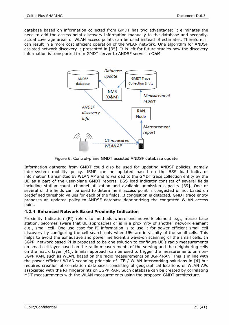
Celtic-Plus SHARING Document D.6.3
Public/Confidential 25 (41)
database based on information collected from GMDT has two advantages: it eliminates the
need to add the access point discovery information manually to the database and secondly,
actual coverage areas of WLAN access points can be used instead of estimates. Therefore, it
can result in a more cost efficient operation of the WLAN network. One algorithm for ANDSF
assisted network discovery is presented in [35]. It is left for future studies how the discovery
information is transported from GMDT server to ANDSF server in O&M.
Figure 6. Control-plane GMDT assisted ANDSF database update
Information gathered from GMDT could also be used for updating ANDSF policies, namely
inter-system mobility policy. ISMP can be updated based on the BSS load indicator
information transmitted by WLAN AP and forwarded to the GMDT trace collection entity by the
UE as a part of the user-plane GMDT reports. BSS load indicator consists of several fields
including station count, channel utilization and available admission capacity [39]. One or
several of the fields can be used to determine if access point is congested or not based on
predefined threshold values for each of the fields. If congestion is detected, GMDT trace entity
proposes an updated policy to ANDSF database deprioritizing the congested WLAN access
point.
4.2.4 Enhanced Network Based Proximity Indication
Proximity Indication (PI) refers to methods where one network element e.g., macro base
station, becomes aware that UE approaches or is in a proximity of another network element
e.g., small cell. One use case for PI information is to use it for power efficient small cell
discovery by configuring the cell search only when UEs are in vicinity of the small cells. This
helps to avoid the exhaustive and power inefficient always-on scanning of the small cells. In
3GPP, network based PI is proposed to be one solution to configure UE’s radio measurements
on small cell layer based on the radio measurements of the serving and the neighboring cells
on the macro layer [41]. Similar approach can be used to trigger the measurements on non-
3GPP RAN, such as WLAN, based on the radio measurements on 3GPP RAN. This is in line with
the power efficient WLAN scanning principle of LTE / WLAN interworking solutions in [4] but
requires creation of correlation databases consisting of geographical locations of WLAN APs
associated with the RF fingerprints on 3GPP RAN. Such database can be created by correlating
MDT measurements with the WLAN measurements using the proposed GMDT architecture.
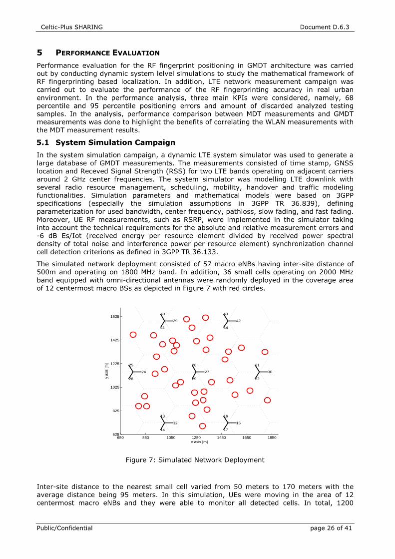
Celtic-Plus SHARING Document D.6.3
Public/Confidential page 26 of 41
5 PERFORMANCE EVALUATION
Performance evaluation for the RF fingerprint positioning in GMDT architecture was carried
out by conducting dynamic system lelvel simulations to study the mathematical framework of
RF fingerprinting based localization. In addition, LTE network measurement campaign was
carried out to evaluate the performance of the RF fingerprinting accuracy in real urban
environment. In the performance analysis, three main KPIs were considered, namely, 68
percentile and 95 percentile positioning errors and amount of discarded analyzed testing
samples. In the analysis, performance comparison between MDT measurements and GMDT
measurements was done to highlight the benefits of correlating the WLAN measurements with
the MDT measurement results.
5.1 System Simulation Campaign
In the system simulation campaign, a dynamic LTE system simulator was used to generate a
large database of GMDT measurements. The measurements consisted of time stamp, GNSS
location and Receved Signal Strength (RSS) for two LTE bands operating on adjacent carriers
around 2 GHz center frequencies. The system simulator was modelling LTE downlink with
several radio resource management, scheduling, mobility, handover and traffic modeling
functionalities. Simulation parameters and mathematical models were based on 3GPP
specifications (especially the simulation assumptions in 3GPP TR 36.839), defining
parameterization for used bandwidth, center frequency, pathloss, slow fading, and fast fading.
Moreover, UE RF measurements, such as RSRP, were implemented in the simulator taking
into account the technical requirements for the absolute and relative measurement errors and
-6 dB Es/Iot (received energy per resource element divided by received power spectral
density of total noise and interference power per resource element) synchronization channel
cell detection criterions as defined in 3GPP TR 36.133.
The simulated network deployment consisted of 57 macro eNBs having inter-site distance of
500m and operating on 1800 MHz band. In addition, 36 small cells operating on 2000 MHz
band equipped with omni-directional antennas were randomly deployed in the coverage area
of 12 centermost macro BSs as depicted in Figure 7 with red circles.
Figure 7: Simulated Network Deployment
Inter-site distance to the nearest small cell varied from 50 meters to 170 meters with the
average distance being 95 meters. In this simulation, UEs were moving in the area of 12
centermost macro eNBs and they were able to monitor all detected cells. In total, 1200
650 850 1050 1250 1450 1650 1850625
825
1025
1225
1425
1625
12
13
14
15
16
17
24
25
26
27
28
29
30
31
32
39
40
41
42
43
44
x axis [m]
y ax
is [m
]
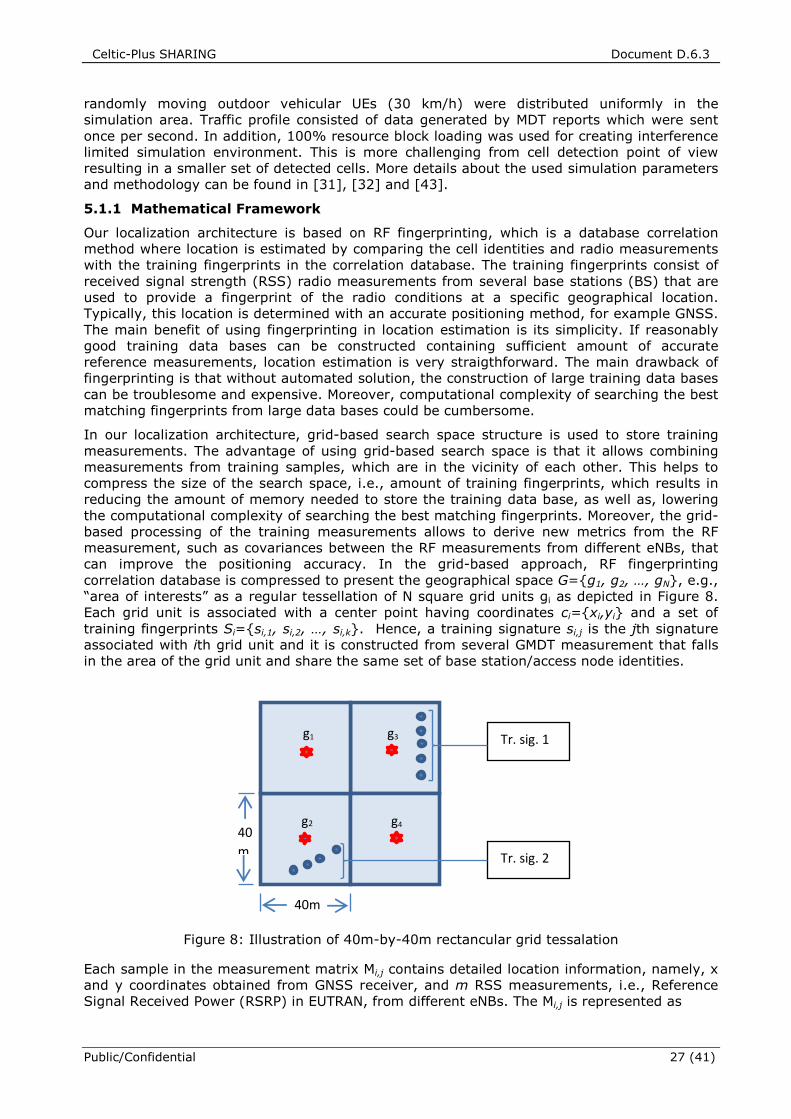
Celtic-Plus SHARING Document D.6.3
Public/Confidential 27 (41)
randomly moving outdoor vehicular UEs (30 km/h) were distributed uniformly in the
simulation area. Traffic profile consisted of data generated by MDT reports which were sent
once per second. In addition, 100% resource block loading was used for creating interference
limited simulation environment. This is more challenging from cell detection point of view
resulting in a smaller set of detected cells. More details about the used simulation parameters
and methodology can be found in [31], [32] and [43].
5.1.1 Mathematical Framework
Our localization architecture is based on RF fingerprinting, which is a database correlation
method where location is estimated by comparing the cell identities and radio measurements
with the training fingerprints in the correlation database. The training fingerprints consist of
received signal strength (RSS) radio measurements from several base stations (BS) that are
used to provide a fingerprint of the radio conditions at a specific geographical location.
Typically, this location is determined with an accurate positioning method, for example GNSS.
The main benefit of using fingerprinting in location estimation is its simplicity. If reasonably
good training data bases can be constructed containing sufficient amount of accurate
reference measurements, location estimation is very straigthforward. The main drawback of
fingerprinting is that without automated solution, the construction of large training data bases
can be troublesome and expensive. Moreover, computational complexity of searching the best
matching fingerprints from large data bases could be cumbersome.
In our localization architecture, grid-based search space structure is used to store training
measurements. The advantage of using grid-based search space is that it allows combining
measurements from training samples, which are in the vicinity of each other. This helps to
compress the size of the search space, i.e., amount of training fingerprints, which results in
reducing the amount of memory needed to store the training data base, as well as, lowering
the computational complexity of searching the best matching fingerprints. Moreover, the grid-
based processing of the training measurements allows to derive new metrics from the RF
measurement, such as covariances between the RF measurements from different eNBs, that
can improve the positioning accuracy. In the grid-based approach, RF fingerprinting
correlation database is compressed to present the geographical space G={g1, g2, …, gN}, e.g.,
“area of interests” as a regular tessellation of N square grid units gi as depicted in Figure 8.
Each grid unit is associated with a center point having coordinates ci={xi,yi} and a set of
training fingerprints Si={si,1, si,2, …, si,k}. Hence, a training signature si,j is the jth signature
associated with ith grid unit and it is constructed from several GMDT measurement that falls
in the area of the grid unit and share the same set of base station/access node identities.
Figure 8: Illustration of 40m-by-40m rectancular grid tessalation
Each sample in the measurement matrix Mi,j contains detailed location information, namely, x
and y coordinates obtained from GNSS receiver, and m RSS measurements, i.e., Reference
Signal Received Power (RSRP) in EUTRAN, from different eNBs. The Mi,j is represented as
Tr. sig. 1
Tr. sig. 2
40m
g1
g2
g3
g4
40
m
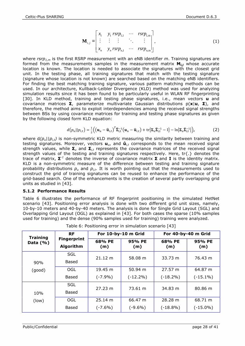
Celtic-Plus SHARING Document D.6.3
Public/Confidential page 28 of 41
1 1 1,1 1,m
,
n,1 n,m
i j
n n
x y rsrp rsrp
x y rsrp rsrp
=
M
L
M M M O M
L
, (1)
where rsrp1,m is the first RSRP measurement with an eNB identifier m. Training signatures are
formed from the measurements samples in the measurement matrix Mi,j whose accurate
location is known. The location is needed to associate the signatures with the closest grid
unit. In the testing phase, all training signatures that match with the testing signature
(signature whose location is not known) are searched based on the matching eNB identifiers.
For finding the best matching training signature, various pattern matching methods can be
used. In our architecture, Kullback-Leibler Divergence (KLD) method was used for analyzing
simulation results since it has been found to be particularly useful in WLAN RF fingerprinting
[30]. In KLD method, training and testing phase signatures, i.e., mean vectors u and
covariance matrices Σ, parameterize multivariate Gaussian distributions p(x|u, Σ), and
therefore, the method aims to exploit interdependencies among the received signal strengths
between BSs by using covariance matrices for training and testing phase signatures as given
by the following closed form KLD equation:
����||��,� = �� ��� − ���,�
����,������ − ���,� + tr������,�
�� − I� − ln �����,��� !, (2)
where d(pu||pi,t) is non-symmetric KLD metric measuring the similarity between training and
testing signatures. Moreover, vectors uu, and ûi,t corresponds to the mean received signal
strength values, while Σu and Σi,t represents the covariance matrices of the received signal
strength values of the testing and training signatures respectively. Here, tr{.} denotes the
trace of matrix, Σ-1 denotes the inverse of covariance matrix Σ and I is the identity matrix.
KLD is a non-symmetric measure of the difference between testing and training signature
probability distributions pu and pi,t. It is worth pointing out that the measurements used to
construct the grid of training signatures can be reused to enhance the performance of the
grid-based search. One of the enhancements is the creation of several partly overlapping grid
units as studied in [43].
5.1.2 Performance Results
Table 6 illustrates the performance of RF fingerprint positioning in the simulated HetNet
scenario [43]. Positioning error analysis is done with two different grid unit sizes, namely,
10-by-10 meters and 40-by-40 meters. The analysis is done for Single Grid Layout (SGL) and
Overlapping Grid Layout (OGL) as explained in [43]. For both cases the sparse (10% samples
used for training) and the dense (90% samples used for training) training were analyzed.
Table 6: Positioning error in simulation scenario [43]
Training Data (%)
RF Fingerprint
Algorithm
For 10-by-10 m Grid For 40-by-40 m Grid
68% PE (m)
95% PE (m)
68% PE (m)
95% PE (m)
90%
(good)
SGL
Based 21.12 m 58.08 m 33.73 m 76.43 m
OGL
Based
19.45 m
(-7.9%)
50.94 m
(-12.2%)
27.57 m
(-18.2%)
64.87 m
(-15.1%)
10%
(low)
SGL
Based 27.23 m 73.61 m 34.83 m 80.86 m
OGL
Based
25.14 m
(-7.6%)
66.47 m
(-9.6%)
28.28 m
(-18.8%)
68.71 m
(-15.0%)
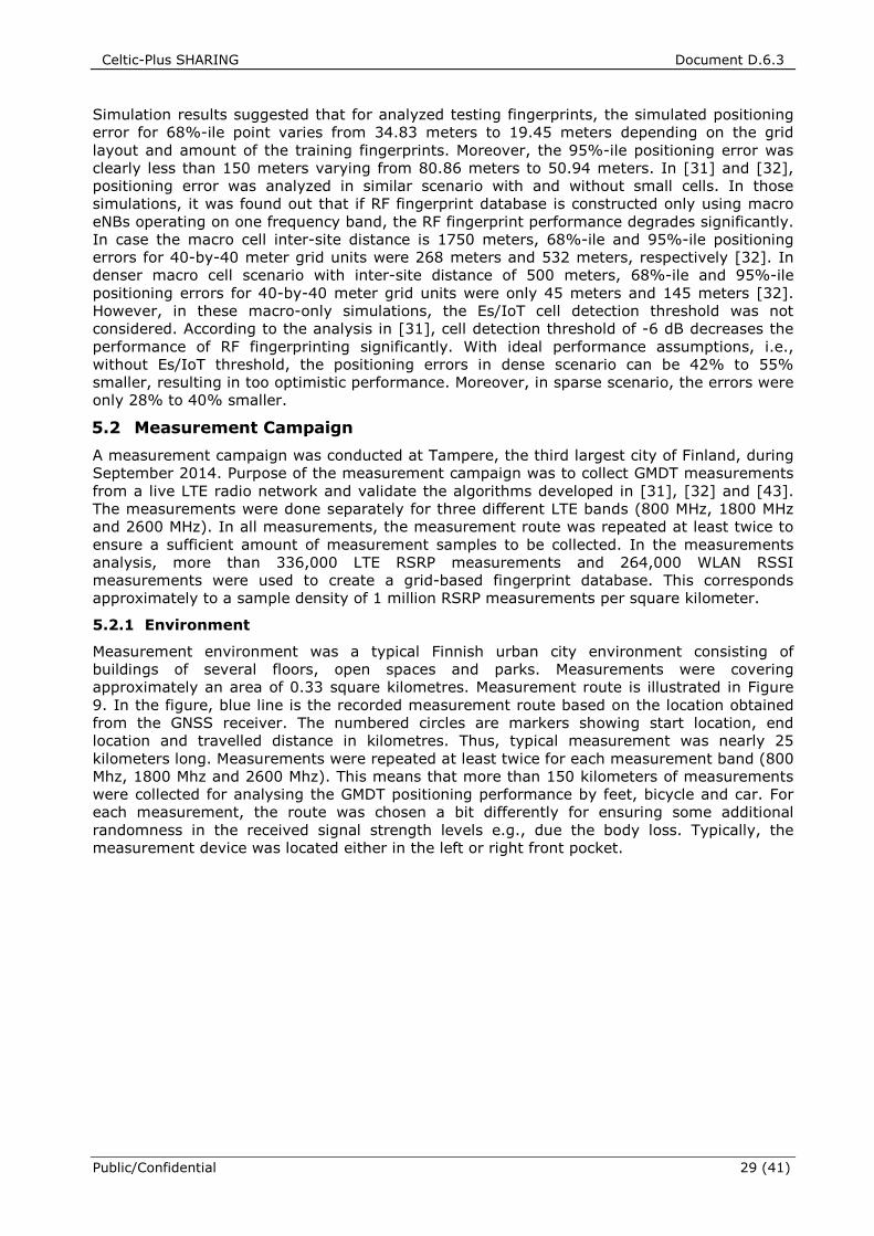
Celtic-Plus SHARING Document D.6.3
Public/Confidential 29 (41)
Simulation results suggested that for analyzed testing fingerprints, the simulated positioning
error for 68%-ile point varies from 34.83 meters to 19.45 meters depending on the grid
layout and amount of the training fingerprints. Moreover, the 95%-ile positioning error was
clearly less than 150 meters varying from 80.86 meters to 50.94 meters. In [31] and [32],
positioning error was analyzed in similar scenario with and without small cells. In those
simulations, it was found out that if RF fingerprint database is constructed only using macro
eNBs operating on one frequency band, the RF fingerprint performance degrades significantly.
In case the macro cell inter-site distance is 1750 meters, 68%-ile and 95%-ile positioning
errors for 40-by-40 meter grid units were 268 meters and 532 meters, respectively [32]. In
denser macro cell scenario with inter-site distance of 500 meters, 68%-ile and 95%-ile
positioning errors for 40-by-40 meter grid units were only 45 meters and 145 meters [32].
However, in these macro-only simulations, the Es/IoT cell detection threshold was not
considered. According to the analysis in [31], cell detection threshold of -6 dB decreases the
performance of RF fingerprinting significantly. With ideal performance assumptions, i.e.,
without Es/IoT threshold, the positioning errors in dense scenario can be 42% to 55%
smaller, resulting in too optimistic performance. Moreover, in sparse scenario, the errors were
only 28% to 40% smaller.
5.2 Measurement Campaign
A measurement campaign was conducted at Tampere, the third largest city of Finland, during
September 2014. Purpose of the measurement campaign was to collect GMDT measurements
from a live LTE radio network and validate the algorithms developed in [31], [32] and [43].
The measurements were done separately for three different LTE bands (800 MHz, 1800 MHz
and 2600 MHz). In all measurements, the measurement route was repeated at least twice to
ensure a sufficient amount of measurement samples to be collected. In the measurements
analysis, more than 336,000 LTE RSRP measurements and 264,000 WLAN RSSI
measurements were used to create a grid-based fingerprint database. This corresponds
approximately to a sample density of 1 million RSRP measurements per square kilometer.
5.2.1 Environment
Measurement environment was a typical Finnish urban city environment consisting of
buildings of several floors, open spaces and parks. Measurements were covering
approximately an area of 0.33 square kilometres. Measurement route is illustrated in Figure
9. In the figure, blue line is the recorded measurement route based on the location obtained
from the GNSS receiver. The numbered circles are markers showing start location, end
location and travelled distance in kilometres. Thus, typical measurement was nearly 25
kilometers long. Measurements were repeated at least twice for each measurement band (800
Mhz, 1800 Mhz and 2600 Mhz). This means that more than 150 kilometers of measurements
were collected for analysing the GMDT positioning performance by feet, bicycle and car. For
each measurement, the route was chosen a bit differently for ensuring some additional
randomness in the received signal strength levels e.g., due the body loss. Typically, the
measurement device was located either in the left or right front pocket.
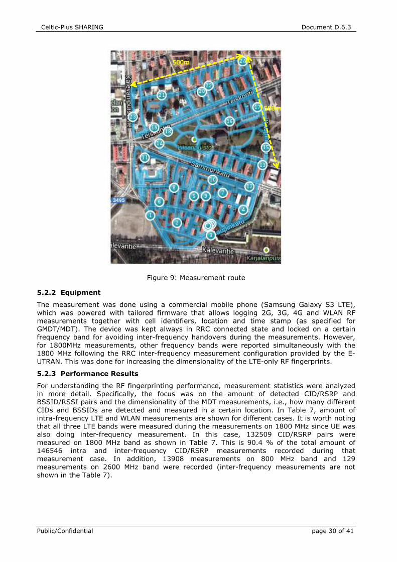
Celtic-Plus SHARING Document D.6.3
Public/Confidential page 30 of 41
Figure 9: Measurement route
5.2.2 Equipment
The measurement was done using a commercial mobile phone (Samsung Galaxy S3 LTE),
which was powered with tailored firmware that allows logging 2G, 3G, 4G and WLAN RF
measurements together with cell identifiers, location and time stamp (as specified for
GMDT/MDT). The device was kept always in RRC connected state and locked on a certain
frequency band for avoiding inter-frequency handovers during the measurements. However,
for 1800MHz measurements, other frequency bands were reported simultaneously with the
1800 MHz following the RRC inter-frequency measurement configuration provided by the E-
UTRAN. This was done for increasing the dimensionality of the LTE-only RF fingerprints.
5.2.3 Performance Results
For understanding the RF fingerprinting performance, measurement statistics were analyzed
in more detail. Specifically, the focus was on the amount of detected CID/RSRP and
BSSID/RSSI pairs and the dimensionality of the MDT measurements, i.e., how many different
CIDs and BSSIDs are detected and measured in a certain location. In Table 7, amount of
intra-frequency LTE and WLAN measurements are shown for different cases. It is worth noting
that all three LTE bands were measured during the measurements on 1800 MHz since UE was
also doing inter-frequency measurement. In this case, 132509 CID/RSRP pairs were
measured on 1800 MHz band as shown in Table 7. This is 90.4 % of the total amount of
146546 intra and inter-frequency CID/RSRP measurements recorded during that
measurement case. In addition, 13908 measurements on 800 MHz band and 129
measurements on 2600 MHz band were recorded (inter-frequency measurements are not
shown in the Table 7).
500m
500m
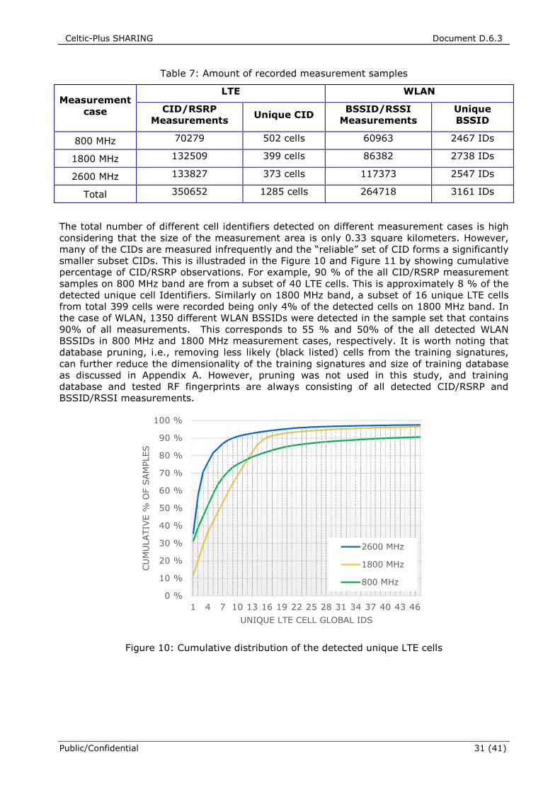
Celtic-Plus SHARING Document D.6.3
Public/Confidential 31 (41)
Table 7: Amount of recorded measurement samples
Measurement case
LTE WLAN
CID/RSRP Measurements
Unique CID BSSID/RSSI
Measurements Unique BSSID
800 MHz 70279 502 cells 60963 2467 IDs
1800 MHz 132509 399 cells 86382 2738 IDs
2600 MHz 133827 373 cells 117373 2547 IDs
Total 350652 1285 cells 264718 3161 IDs
The total number of different cell identifiers detected on different measurement cases is high
considering that the size of the measurement area is only 0.33 square kilometers. However,
many of the CIDs are measured infrequently and the “reliable” set of CID forms a significantly
smaller subset CIDs. This is illustraded in the Figure 10 and Figure 11 by showing cumulative
percentage of CID/RSRP observations. For example, 90 % of the all CID/RSRP measurement
samples on 800 MHz band are from a subset of 40 LTE cells. This is approximately 8 % of the
detected unique cell Identifiers. Similarly on 1800 MHz band, a subset of 16 unique LTE cells
from total 399 cells were recorded being only 4% of the detected cells on 1800 MHz band. In
the case of WLAN, 1350 different WLAN BSSIDs were detected in the sample set that contains
90% of all measurements. This corresponds to 55 % and 50% of the all detected WLAN
BSSIDs in 800 MHz and 1800 MHz measurement cases, respectively. It is worth noting that
database pruning, i.e., removing less likely (black listed) cells from the training signatures,
can further reduce the dimensionality of the training signatures and size of training database
as discussed in Appendix A. However, pruning was not used in this study, and training
database and tested RF fingerprints are always consisting of all detected CID/RSRP and
BSSID/RSSI measurements.
Figure 10: Cumulative distribution of the detected unique LTE cells
0 %
10 %
20 %
30 %
40 %
50 %
60 %
70 %
80 %
90 %
100 %
1 4 7 10 13 16 19 22 25 28 31 34 37 40 43 46
CU
MU
LATIV
E %
OF S
AM
PLES
UNIQUE LTE CELL GLOBAL IDS
2600 MHz
1800 MHz
800 MHz
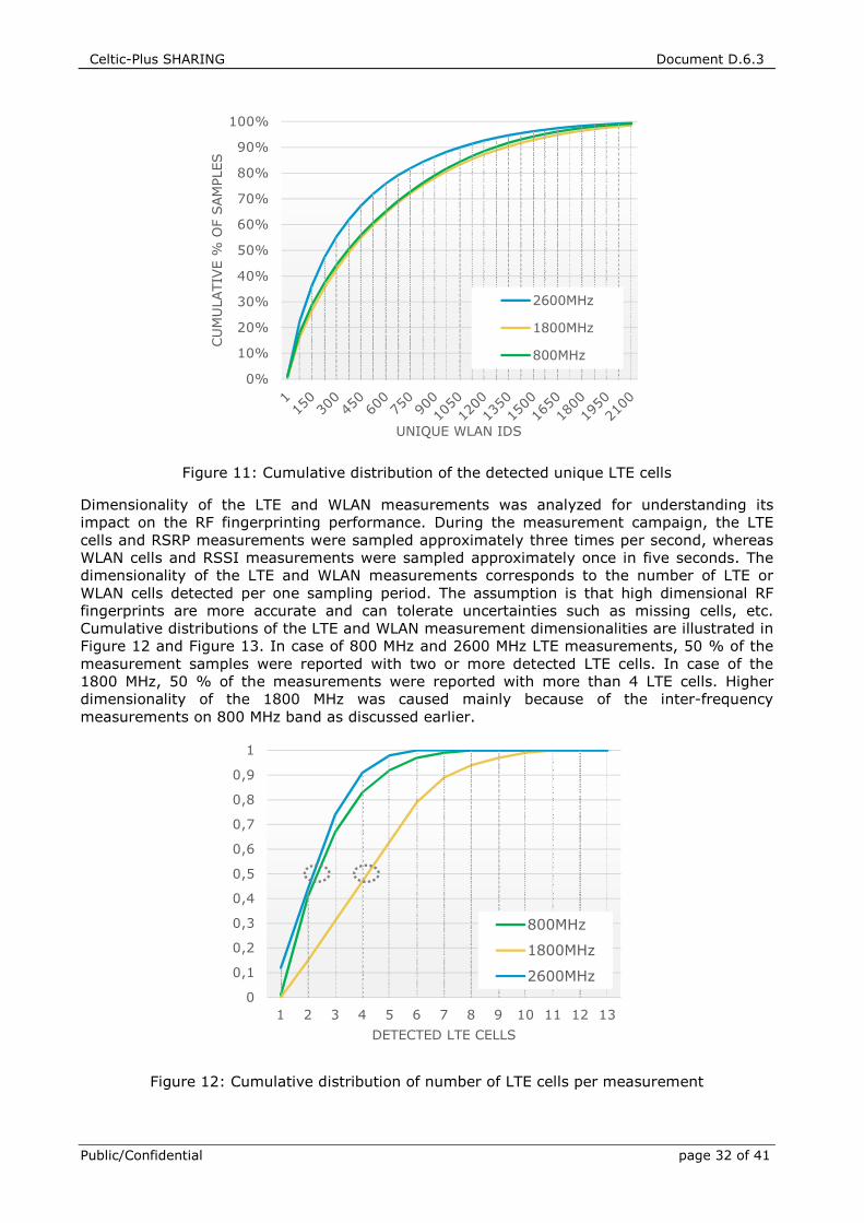
Celtic-Plus SHARING Document D.6.3
Public/Confidential page 32 of 41
Figure 11: Cumulative distribution of the detected unique LTE cells
Dimensionality of the LTE and WLAN measurements was analyzed for understanding its
impact on the RF fingerprinting performance. During the measurement campaign, the LTE
cells and RSRP measurements were sampled approximately three times per second, whereas
WLAN cells and RSSI measurements were sampled approximately once in five seconds. The
dimensionality of the LTE and WLAN measurements corresponds to the number of LTE or
WLAN cells detected per one sampling period. The assumption is that high dimensional RF
fingerprints are more accurate and can tolerate uncertainties such as missing cells, etc.
Cumulative distributions of the LTE and WLAN measurement dimensionalities are illustrated in
Figure 12 and Figure 13. In case of 800 MHz and 2600 MHz LTE measurements, 50 % of the
measurement samples were reported with two or more detected LTE cells. In case of the
1800 MHz, 50 % of the measurements were reported with more than 4 LTE cells. Higher
dimensionality of the 1800 MHz was caused mainly because of the inter-frequency
measurements on 800 MHz band as discussed earlier.
Figure 12: Cumulative distribution of number of LTE cells per measurement
0%
10%
20%
30%
40%
50%
60%
70%
80%
90%
100%
CU
MU
LATIV
E %
OF S
AM
PLES
UNIQUE WLAN IDS
2600MHz
1800MHz
800MHz
0
0,1
0,2
0,3
0,4
0,5
0,6
0,7
0,8
0,9
1
1 2 3 4 5 6 7 8 9 10 11 12 13
DETECTED LTE CELLS
800MHz
1800MHz
2600MHz
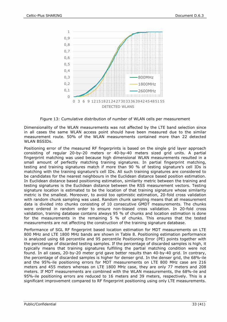
Celtic-Plus SHARING Document D.6.3
Public/Confidential 33 (41)
Figure 13: Cumulative distribution of number of WLAN cells per measurement
Dimensionality of the WLAN measurements was not affected by the LTE band selection since
in all cases the same WLAN access point should have been measured due to the similar
measurement route. 50% of the WLAN measurements contained more than 22 detected
WLAN BSSIDs.
Positioning error of the measured RF fingerprints is based on the single grid layer approach
consisting of regular 20-by-20 meters or 40-by-40 meters sized grid units. A partial
fingerprint matching was used because high dimensional WLAN measurements resulted in a
small amount of perfectly matching training signatures. In partial fingerprint matching,
testing and training signatures match if more than 90 % of testing signature’s cell IDs is
matching with the training signature’s cell IDs. All such training signatures are considered to
be candidates for the nearest neighbours in the Euclidean distance based position estimation.
In Euclidean distance based positioning estimation, similarity metric between the training and
testing signatures is the Euclidean distance between the RSS measurement vectors. Testing
signature location is estimated to be the location of that training signature whose similarity
metric is the smallest. Moreover, to avoid too optimistic estimation, 20-fold cross validation
with random chunk sampling was used. Random chunk sampling means that all measurement
data is divided into chunks consisting of 10 consecutive GMDT measurements. The chunks
were ordered in random order to ensure non-biased cross validation. In 20-fold cross
validation, training database contains always 95 % of chunks and location estimation is done
for the measurements in the remaining 5 % of chunks. This ensures that the tested
measurements are not affecting the construction of the training signature database.
Performance of SGL RF fingerprint based location estimation for MDT measurements on LTE
800 MHz and LTE 1800 MHz bands are shown in Table 8. Positioning estimation performance
is analyzed using 68 percentile and 95 percentile Positioning Error (PE) points together with
the percetange of discarded testing samples. If the percentage of discarded samples is high, it
typically means that training signatures fulfilling the partial matching condition were not
found. In all cases, 20-by-20 meter grid gave better results than 40-by-40 grid. In contrary,
the percentage of discarded samples is higher for denser grid. In the denser grid, the 68%-ile
and the 95%-ile positioning errors for MDT measurements on LTE 800 MHz case are 216
meters and 455 meters whereas on LTE 1800 MHz case, they are only 77 meters and 208
meters. If MDT measurements are combined with the WLAN measurements, the 68%-ile and
95%-ile positioning errors are reduced to 16 meters and 39 meters, respectively. This is a
significant improvement compared to RF fingerprint positioning using only LTE measurements.
0
0,1
0,2
0,3
0,4
0,5
0,6
0,7
0,8
0,9
1
0 3 6 9 121518212427303336394245485155
DETECTED WLANS
800MHz
1800MHz
2600MHz
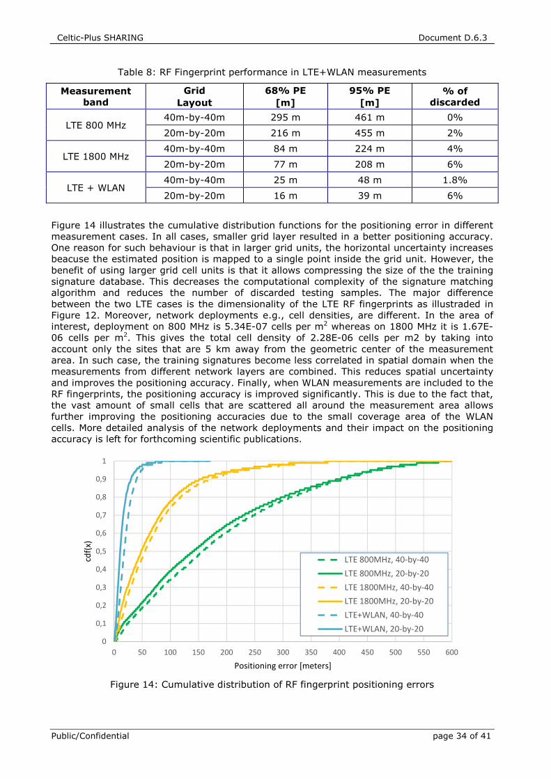
Celtic-Plus SHARING Document D.6.3
Public/Confidential page 34 of 41
Table 8: RF Fingerprint performance in LTE+WLAN measurements
Measurement band
Grid
Layout
68% PE
[m]
95% PE
[m] % of
discarded
LTE 800 MHz 40m-by-40m 295 m 461 m 0%
20m-by-20m 216 m 455 m 2%
LTE 1800 MHz 40m-by-40m 84 m 224 m 4%
20m-by-20m 77 m 208 m 6%
LTE + WLAN 40m-by-40m 25 m 48 m 1.8%
20m-by-20m 16 m 39 m 6%
Figure 14 illustrates the cumulative distribution functions for the positioning error in different
measurement cases. In all cases, smaller grid layer resulted in a better positioning accuracy.
One reason for such behaviour is that in larger grid units, the horizontal uncertainty increases
beacuse the estimated position is mapped to a single point inside the grid unit. However, the
benefit of using larger grid cell units is that it allows compressing the size of the the training
signature database. This decreases the computational complexity of the signature matching
algorithm and reduces the number of discarded testing samples. The major difference
between the two LTE cases is the dimensionality of the LTE RF fingerprints as illustraded in
Figure 12. Moreover, network deployments e.g., cell densities, are different. In the area of
interest, deployment on 800 MHz is 5.34E-07 cells per m2 whereas on 1800 MHz it is 1.67E-
06 cells per m2. This gives the total cell density of 2.28E-06 cells per m2 by taking into
account only the sites that are 5 km away from the geometric center of the measurement
area. In such case, the training signatures become less correlated in spatial domain when the
measurements from different network layers are combined. This reduces spatial uncertainty
and improves the positioning accuracy. Finally, when WLAN measurements are included to the
RF fingerprints, the positioning accuracy is improved significantly. This is due to the fact that,
the vast amount of small cells that are scattered all around the measurement area allows
further improving the positioning accuracies due to the small coverage area of the WLAN
cells. More detailed analysis of the network deployments and their impact on the positioning
accuracy is left for forthcoming scientific publications.
Figure 14: Cumulative distribution of RF fingerprint positioning errors
0
0,1
0,2
0,3
0,4
0,5
0,6
0,7
0,8
0,9
1
0 50 100 150 200 250 300 350 400 450 500 550 600
cdf(
x)
Positioning error [meters]
LTE 800MHz, 40-by-40
LTE 800MHz, 20-by-20
LTE 1800MHz, 40-by-40
LTE 1800MHz, 20-by-20
LTE+WLAN, 40-by-40
LTE+WLAN, 20-by-20
Celtic-Plus SHARING Document D.6.3
Public/Confidential 35 (41)
6 CONCLUSION
This deliverable introduced an enhancement to LTE Release 11 MDT functionality. The
enhancement makes it possible to incorporate radio coverage measurements of WLAN access
points into MDT measurements. It is evident that network automation is essential in next
generation multi-layer, multi-RAT heterogeneous networks in order to optimize network
performance and reduce the costs of mobile operators. The proposed GMDT functionality can
help to automate the collection of location-aware radio measurements from WLAN access
networks and combine these with 3GPP MDT measurements. Both control-plane and user-
plane solutions for enabling generalized MDT were outlined. The control-plane solution was
aligned as much as possible with 3GPP Study Item on WLAN/3GPP radio interworking with
regard to measurements and triggering events. The user-plane solution allows correlating
GMDT measurements with MDT measuremenst using user-plane protocols e.g., OMA-DM
protocol, for conveying WLAN measurements to O&M with assistance information. However,
3GPP concluded that LTE/WLAN interworking solution does not mandate WLAN measurement
reporting from UE to eNB. Thus, the proposed user-plane solution is seen more applicable at
the moment for enabling GMDT functionality.
Several important mobile operator use cases for generalized MDT were presented such as
WLAN coverage mapping, ANDSF database update, network based proximity indication and
RF fingerprint localization. Performance evaluation of the GMDT based RF fingerprinting was
carried out by conducting the system-level simulations and LTE live network measurements.
The performance evaluation suggests that by correlating MDT measurements with WLAN
measurements, the positioning accuracy of outdoor RF fingerprinting can be significantly
improved. In the studied measurements, location estimation error for two-thirds of all MDT
measurements is decreased by 79 % to 70 % if WLAN measurements are utilized in addition
to LTE measurements. Moreover, since WLAN based positioning is already widely used
indoors, the proposed approach is seen as an attractive solution to further enhance the
availability of detailed location information of MDT measurements collected from indoor
locations. Hence, by linking MDT measurements with WLAN measurements operators can
collect low cost extensive and detailed coverage maps autonomously improving significantly
positioning performance of MDT measurements.
Celtic-Plus SHARING Document D.6.3
Public/Confidential page 36 of 41
REFERENCES
[1] IDATE, “Mobile traffic forecast 2010-2020 report”, UMTS Forum Report#44, May 2011.
[2] Cisco, “802.11ac: The fifth generation of Wi-Fi” technical white paper, August 2012.
[3] 3GPP TR 36.805, “Study on minimization of drive-tests in Next Generation Networks”, v.9.0.0,
December 2009.
[4] 3GPP TR 37.834: “Technical Specification Group Radio Access Network; Study on WLAN/3GPP Radio
Interworking (Release 12)”, version 12.0.0, December 2013-12
[5] 3GPP, TS 23.234, “3GPP system to Wireless Local Area Network (WLAN) Interworking, System
Description (Release 6)”, v6.0.0
[6] 3GPP TS 23.402, “Architecture enhancements for non-3GPP accesses”, v.12.2.0, September 2013.
[7] 3GPP TS 03.71, “Location Services (LCS); Functional description; Stage 2”, version 8.9.0, June
2004, available (http://www.3gpp.org)
[8] 3GPP TS 04.31, “Location Services (LCS); Mobile Station (MS) - Serving Mobile Location Centre
(SMLC) Radio Resource LCS Protocol (RRLP)”, version 8.18.0, June 2006, available [online]
(http://www.3gpp.org)
[9] Wireless E99 Location Accuracy Requirements, Second Report and Order, FCC, September 2010.
[10] 3GPP TS 23.271, "Functional stage 2 description of Location Services (LCS)", version 12.1.0, June
2014, available [online] (http://www.3gpp.org)
[11] 3GPP TS 36.305, "Stage 2 functional specification of User Equipment (UE) positioning in E-UTRAN"
[12] 3GPP TS 36.455, Evolved Universal Terrestrial Radio Access (E-UTRA); LTE Positioning Protocol A
(LPPa), version 12.0.0, June 2014.
[13] 3GPP TS 36.355, "Evolved Universal Terrestrial Radio Access (E-UTRA); LTE Positioning Protocol
(LPP)", version 12.2.0, June 2014.
[14] Open Mobile Alliance, OMA AD SUPL: "Secure User Plane Location Architecture", available [online]
(http://www.openmobilealliance.org).
[15] Open Mobile Alliance, OMA TS ULP: "User Plane Location Protocol", available [online]
(http://www.openmobilealliance.org).
[16] Open Mobile Alliance, OMA TS LPPe: “LPP Extensions Specification”, available [online]
(http://www.openmobilealliance.org).
[17] Ericsson White Paper, “Positioning with LTE: Maximizing Performance through Integration”,
September 2011.
[18] 3GPP TS 24.312, "Access Network Discovery and Selection Function (ANDSF) Management Object
(MO)", V12.6.1, November 2014.
[19] 3GPP TS 36.304, "Evolved Universal Terrestrial Radio Access (E-UTRA); User Equipment (UE)
procedures in idle mode",
[20] Universal Terrestrial Radio Access (UTRA) and Evolved Universal Terrestrial Radio Access (E-UTRA);
Radio measurement collection for Minimization of Drive Tests (MDT); Overall description; Stage 2,
3GPP Specification 37.320, V. 11.3.0
[21] 3GPP TS 36.300, “Evolved Universal Terrestrial Radio Access (E-UTRA) and Evolved Universal
Terrestrial Radio Access Network (E-UTRAN); Overall description; Stage 2”
[22] NGMN Alliance, “NGMN Use Cases related to Self Organising Network, Overall Description”,
Deliverable, May 2007.
[23] 3GPP TS 37.320, “Radio measurement collection for Minimization of Drive Tests,” v.0.7.0, June
2010.
[24] 3GPP RP-111361, “Enhancement of Minimization of Drive Tests for E-UTRAN and UTRAN – Core Part
Approval”, Nokia Siemens Networks, Nokia, MediaTek, September 16, 2011.
[25] Johansson J., Hapsari W.A., Kelly S. and Bodog G., “Minimization of drive tests in 3GPP Release
11”, IEEE Communications Magazine, November 2012.
Celtic-Plus SHARING Document D.6.3
Public/Confidential 37 (41)
[26] Wuri A. Hapsari, Anil Umesh, Mikio Iwamura, Magorzata Tomala, Gyula Bodog, Benoist Sebire:
Minimization of drive tests solution in 3GPP.IEEE Communications Magazine 50(6): 28-36 (2012).
[27] 3GPP TS 32.422: “Subscriber and equipment trace; Trace control and configuration management”,
v.11.0.1, September 2011.
[28] 3GPP TS 36.331: "Evolved Universal Terrestrial Radio Access (E-UTRA); Radio Resource Control
(RRC); Protocol specification", v.10.4.0, December 2011.
[29] Analysys Mason, “The message from MWC 2010: indoor coverage and subscriber management are
the keys to dealing with exponential growth in wireless traffic“, 2010.
[30] D. Milioris et al., “Low-dimensional signal-strength fingerprint-based positioning wireless LANs”, Ad
Hoc Netw., 2012, doi:10.1016/j.adhoc.2011.12.006.
[31] R. Mondal, J. Turkka, T. Ristaniemi and T. Henttonen, “Positioning in heterogeneous small cell
networks using MDT RF fingerprints", In proc. of International Black Sea Conference on
Communications and Networking, Batumi, Georgia, July 2013. (Invited paper)
[32] R. Mondal, J. Turkka, T. Ristaniemi and T. Henttonen, “Performance evaluation of MDT assisted
LTE RF fingerprint framework”, In proc of Seventh International Conference on Mobile Computing
and Ubiquitous Networking, Singapore, January 2014.
[33] The FCC, Fact Sheet—FCC Wireless 911 Requirements, Jan. 2001.
[34] WI-FI roaming – Building on ANDSF and Hotspot2.0, Alcatel-Lucent white paper in collaboration
with BT
[35] D. Triantafyllopoulou, Tao Guo and K. Moessner, “Energy efficient ANDSF-assisted network
discovery for non-3GPP access networks", In proc. of IEEE 17th International Workshop on
Computer Aided Modeling and Design of Communication Links and Networks (CAMAD), September
2012.
[36] R2-133157, “Limitations on WLAN measurements for WLAN/3GPP Radio Interworking”, Broadcom
Corporation, 3GPP TSG-RAN WG2 Meeting #83-BIS October 2013 Ljubljana, Slovenia.
[37] IEEE 802.11k-2008, “IEEE Standard for Information technology--Telecommunications and
information exchange between systems Local and metropolitan area networks--Specific
requirements Part 11: Wireless LAN Medium Access Control (MAC) and Physical Layer (PHY)
Specifications; Amendment 1: Radio Resource Measurement of Wireless LANs”
[38] 3GPP, TS 36.133 v.12.10., “Evolved Universal Terrestrial Radio Access (E-UTRA); Requirements for
support of radio resource management (Release 12)”
[39] IEEE 802.11k-2012, “IEEE Standard for Information technology--Telecommunications and
information exchange between systems Local and metropolitan area networks--Specific
requirements Part 11: Wireless LAN Medium Access Control (MAC) and Physical Layer (PHY)
Specifications; Amendment 1: Radio Resource Measurement of Wireless LANs”
[40] E. Laitinen, E. S. Lohan, J. Talvitie and S. Shrestha, “Access Point Significance Measures in WLAN-
based location”, WPNC, Mar 2012
[41] R2-131675, “Small cell detection”, Ericsson, ST-Ericsson, 3GPP TSG-RAN WG2 #82, May 2013.
[42] NGMN Alliance, ‘NGMN Recommendation on SON and O&M Requirements’, Requirement
specification, December 2008
[43] R. Mondal, J. Turkka, T. Ristaniemi, ‘An Efficient Grid-based RF Fingerprint Positioning Algorithm for
User Location Estimation in Heterogeneous Small Cell Networks’, International Conference on
Localization and GNSS (ICL-GNSS), Helsinki, Finland, June 24-26, 2014.
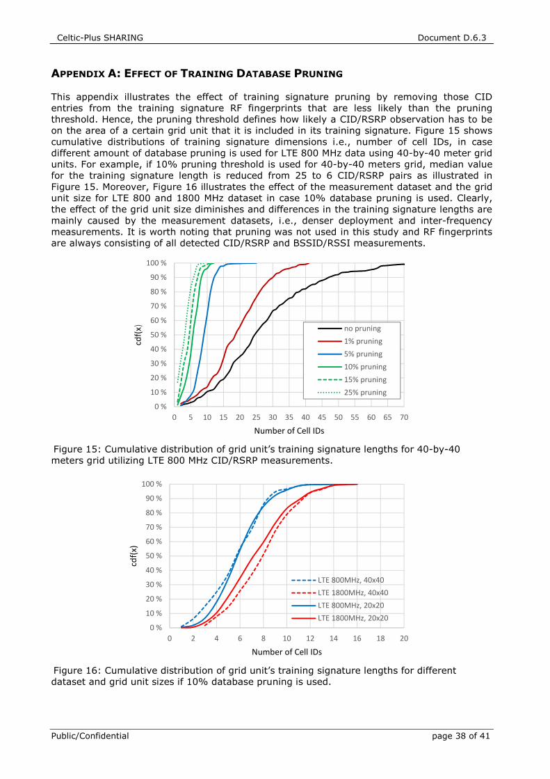
Celtic-Plus SHARING Document D.6.3
Public/Confidential page 38 of 41
APPENDIX A: EFFECT OF TRAINING DATABASE PRUNING
This appendix illustrates the effect of training signature pruning by removing those CID
entries from the training signature RF fingerprints that are less likely than the pruning
threshold. Hence, the pruning threshold defines how likely a CID/RSRP observation has to be
on the area of a certain grid unit that it is included in its training signature. Figure 15 shows
cumulative distributions of training signature dimensions i.e., number of cell IDs, in case
different amount of database pruning is used for LTE 800 MHz data using 40-by-40 meter grid
units. For example, if 10% pruning threshold is used for 40-by-40 meters grid, median value
for the training signature length is reduced from 25 to 6 CID/RSRP pairs as illustrated in
Figure 15. Moreover, Figure 16 illustrates the effect of the measurement dataset and the grid
unit size for LTE 800 and 1800 MHz dataset in case 10% database pruning is used. Clearly,
the effect of the grid unit size diminishes and differences in the training signature lengths are
mainly caused by the measurement datasets, i.e., denser deployment and inter-frequency
measurements. It is worth noting that pruning was not used in this study and RF fingerprints
are always consisting of all detected CID/RSRP and BSSID/RSSI measurements.
Figure 15: Cumulative distribution of grid unit’s training signature lengths for 40-by-40
meters grid utilizing LTE 800 MHz CID/RSRP measurements.
Figure 16: Cumulative distribution of grid unit’s training signature lengths for different
dataset and grid unit sizes if 10% database pruning is used.
0 %
10 %
20 %
30 %
40 %
50 %
60 %
70 %
80 %
90 %
100 %
0 5 10 15 20 25 30 35 40 45 50 55 60 65 70
cdf(
x)
Number of Cell IDs
no pruning
1% pruning
5% pruning
10% pruning
15% pruning
25% pruning
0 %
10 %
20 %
30 %
40 %
50 %
60 %
70 %
80 %
90 %
100 %
0 2 4 6 8 10 12 14 16 18 20
cdf(
x)
Number of Cell IDs
LTE 800MHz, 40x40
LTE 1800MHz, 40x40
LTE 800MHz, 20x20
LTE 1800MHz, 20x20
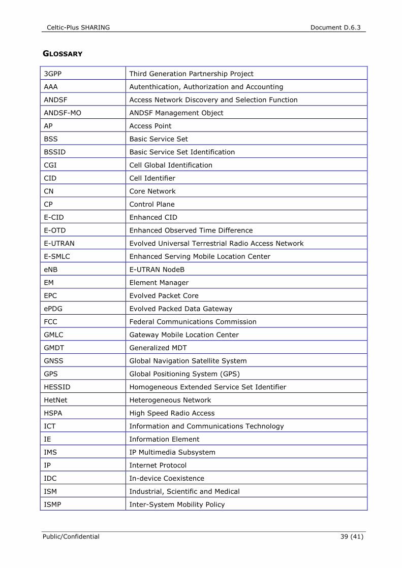
Celtic-Plus SHARING Document D.6.3
Public/Confidential 39 (41)
GLOSSARY
3GPP Third Generation Partnership Project
AAA Autenthication, Authorization and Accounting
ANDSF Access Network Discovery and Selection Function
ANDSF-MO ANDSF Management Object
AP Access Point
BSS Basic Service Set
BSSID Basic Service Set Identification
CGI Cell Global Identification
CID Cell Identifier
CN Core Network
CP Control Plane
E-CID Enhanced CID
E-OTD Enhanced Observed Time Difference
E-UTRAN Evolved Universal Terrestrial Radio Access Network
E-SMLC Enhanced Serving Mobile Location Center
eNB E-UTRAN NodeB
EM Element Manager
EPC Evolved Packet Core
ePDG Evolved Packed Data Gateway
FCC Federal Communications Commission
GMLC Gateway Mobile Location Center
GMDT Generalized MDT
GNSS Global Navigation Satellite System
GPS Global Positioning System (GPS)
HESSID Homogeneous Extended Service Set Identifier
HetNet Heterogeneous Network
HSPA High Speed Radio Access
ICT Information and Communications Technology
IE Information Element
IMS IP Multimedia Subsystem
IP Internet Protocol
IDC In-device Coexistence
ISM Industrial, Scientific and Medical
ISMP Inter-System Mobility Policy
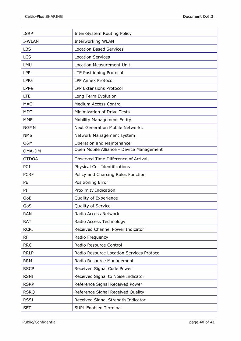
Celtic-Plus SHARING Document D.6.3
Public/Confidential page 40 of 41
ISRP Inter-System Routing Policy
I-WLAN Interworking WLAN
LBS Location Based Services
LCS Location Services
LMU Location Measurement Unit
LPP LTE Positioning Protocol
LPPa LPP Annex Protocol
LPPe LPP Extensions Protocol
LTE Long Term Evolution
MAC Medium Access Control
MDT Minimization of Drive Tests
MME Mobility Management Entity
NGMN Next Generation Mobile Networks
NMS Network Management system
O&M Operation and Maintenance
OMA-DM Open Mobile Alliance - Device Management
OTDOA Observed Time Difference of Arrival
PCI Physical Cell Identifications
PCRF Policy and Charcing Rules Function
PE Positioning Error
PI Proximity Indication
QoE Quality of Experience
QoS Quality of Service
RAN Radio Access Network
RAT Radio Access Technology
RCPI Received Channel Power Indicator
RF Radio Frequency
RRC Radio Resource Control
RRLP Radio Resource Location Services Protocol
RRM Radio Resource Management
RSCP Received Signal Code Power
RSNI Received Signal to Noise Indicator
RSRP Reference Signal Received Power
RSRQ Reference Signal Received Quality
RSSI Received Signal Strength Indicator
SET SUPL Enabled Terminal
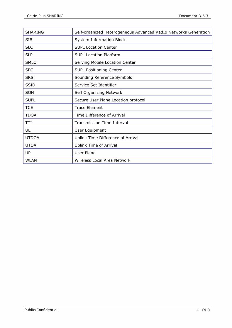
Celtic-Plus SHARING Document D.6.3
Public/Confidential 41 (41)
SHARING Self-organized Heterogeneous Advanced RadIo Networks Generation
SIB System Information Block
SLC SUPL Location Center
SLP SUPL Location Platform
SMLC Serving Mobile Location Center
SPC SUPL Positioning Center
SRS Sounding Reference Symbols
SSID Service Set Identifier
SON Self Organizing Network
SUPL Secure User Plane Location protocol
TCE Trace Element
TDOA Time Difference of Arrival
TTI Transmission Time Interval
UE User Equipment
UTDOA Uplink Time Difference of Arrival
UTOA Uplink Time of Arrival
UP User Plane
WLAN Wireless Local Area Network