shatin to central link consultancy agreement no.: c1104 ......shatin to central link consultancy...
TRANSCRIPT

Shatin to Central Link Consultancy Agreement No.: C1104 Detailed Design for Kai Tak Station and Associated Tunnels Working Paper – Pile Integrity Test to Former Kowloon City Pier


Shatin to Central Link Consultancy Agreement No.: C1104 Detailed Design for Kai Tak Station and Associated Tunnels
i
consulting engineers • planners • managerswww.meinhardtgroup.com
Contents Page 1.0 Introduction ............................................................................................................................1
1.1 Background ..................................................................................................................1 2.0 The Pile Integrity Test ............................................................................................................2
2.1 General.........................................................................................................................2 2.2 Test Result and Its Interpretation..................................................................................2
3.0 Measures to Minimize the Effect on the LTSB and FKCP...................................................3 4.0 Conclusions............................................................................................................................6
Appendices
Appendix A - Extracts of Test Report by Stangers Asia Limited in 2009
Appendix B - Location of Concrete Pillars under Pile Integrity Test on 4 Nov 2010
Appendix C - Results of Pile Integrity Test Carried Out on 4 Nov 2010
Appendix D - Tunnel Alignment (Preliminary Design and Current Proposal)
Appendix E - Section Between Tunnel and FKCP
Appendix F - Ground Monitoring Points around FKCP
Appendix G - Construction Sequence for Mined Tunnel under FKCP Site
Shatin to Central Link Consultancy Agreement No.: C1104 Detailed Design for Kai Tak Station and Associated Tunnels
1
consulting engineers • planners • managerswww.meinhardtgroup.com
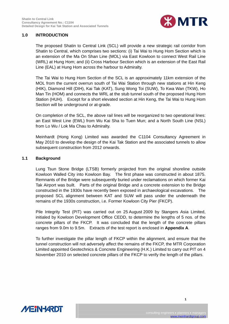
1.0 INTRODUCTION The proposed Shatin to Central Link (SCL) will provide a new strategic rail corridor from Shatin to Central, which comprises two sections: (i) Tai Wai to Hung Hom Section which is an extension of the Ma On Shan Line (MOL) via East Kowloon to connect West Rail Line (WRL) at Hung Hom; and (ii) Cross Harbour Section which is an extension of the East Rail Line (EAL) at Hung Hom across the harbour to Admiralty. The Tai Wai to Hung Hom Section of the SCL is an approximately 11km extension of the MOL from the current overrun south of Tai Wai Station through new stations at Hin Keng (HIK), Diamond Hill (DIH), Kai Tak (KAT), Sung Wong Toi (SUW), To Kwa Wan (TKW), Ho Man Tin (HOM) and connects the WRL at the stub tunnel south of the proposed Hung Hom Station (HUH). Except for a short elevated section at Hin Keng, the Tai Wai to Hung Hom Section will be underground or at-grade. On completion of the SCL, the above rail lines will be reorganized to two operational lines: an East West Line (EWL) from Wu Kai Sha to Tuen Mun; and a North South Line (NSL) from Lo Wu / Lok Ma Chau to Admiralty. Meinhardt (Hong Kong) Limited was awarded the C1104 Consultancy Agreement in May 2010 to develop the design of the Kai Tak Station and the associated tunnels to allow subsequent construction from 2012 onwards.
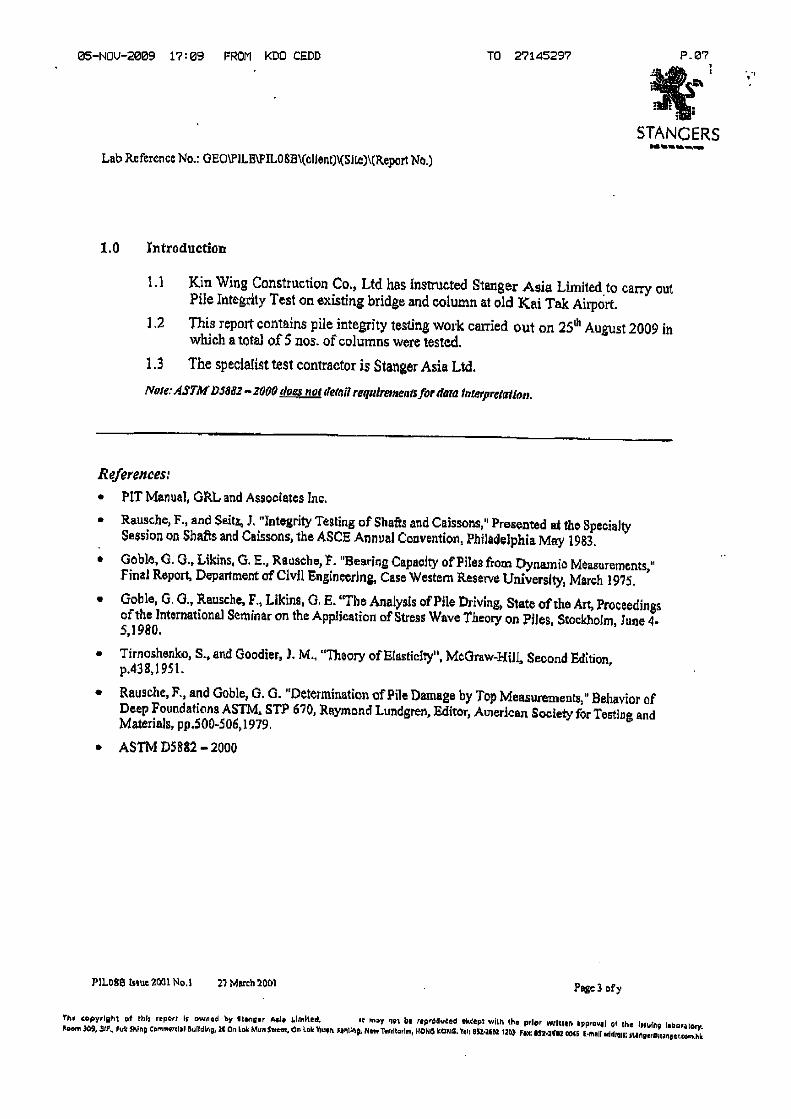
1.1 Background Lung Tsun Stone Bridge (LTSB) formerly projected from the original shoreline outside Kowloon Walled City into Kowloon Bay. The first phase was constructed in about 1875. Remnants of the Bridge were subsequently buried under reclamations on which former Kai Tak Airport was built. Parts of the original Bridge and a concrete extension to the Bridge constructed in the 1930s have recently been exposed in archaeological excavations. The proposed SCL alignment between KAT and SUW will pass under the underneath the remains of the 1930s construction, i.e. Former Kowloon City Pier (FKCP). Pile Integrity Test (PIT) was carried out on 25 August 2009 by Stangers Asia Limited, initialed by Kowloon Development Office CEDD, to determine the lengths of 5 nos. of the concrete pillars of the FKCP. It was concluded that the length of the concrete pillars ranges from 9.0m to 9.5m. Extracts of the test report is enclosed in Appendix A. To further investigate the pillar length of FKCP within the alignment, and ensure that the tunnel construction will not adversely affect the remains of the FKCP, the MTR Corporation Limited appointed Geotechnics & Concrete Engineering (H.K.) Limited to carry out PIT on 4 November 2010 on selected concrete pillars of the FKCP to verify the length of the pillars.

Shatin to Central Link Consultancy Agreement No.: C1104 Detailed Design for Kai Tak Station and Associated Tunnels
2
consulting engineers • planners • managerswww.meinhardtgroup.com
2.0 THE PILE INTEGRITY TEST
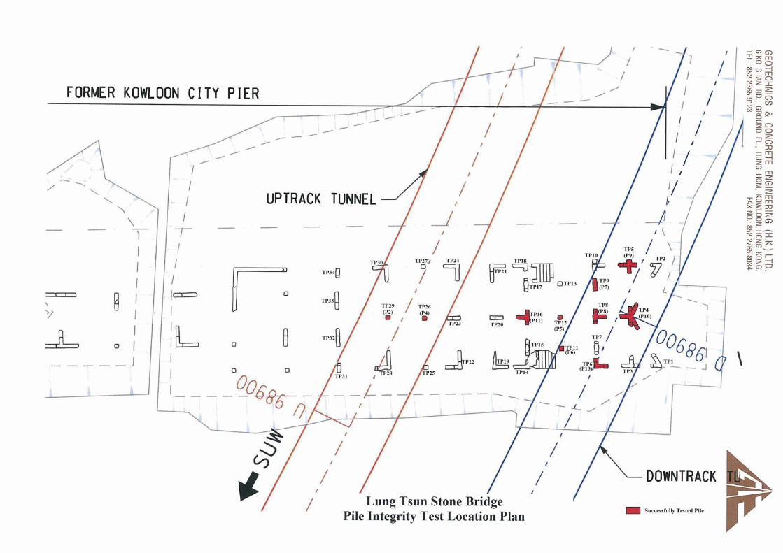
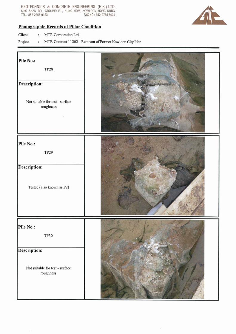
2.1 General Total 34 nos. of concrete pillar of the FKCP are located within the alignment of the MTR Corporation tunnel alignment. 10 nos. of the concrete pillars (namely TP4, TP5, TP6, TP8, TP9, TP11, TP12, TP16, TP26 and TP29) were selected for PIT on 4 November 2010. The concrete pillars tested were selected based on their existing conditions, including the quality of concrete, surface roughness, pile alignment and cleanliness of pillar top. The remaining 24 nos. pillars were found unsuitable for the test. The location of the pillars on which PIT was carried out is shown in Appendix B.
2.2 Test Result and Its Interpretation From the test results, a strong reflection of transmitted signal was observed from 1.7m to 2.2m below the pillar top level at 8 of the pillars (i.e., TP4, TP5, TP6, TP9, TP12, TP16, TP26 and TP29). For TP11, reflected signal was detected at about 2m below pillar top, similar to the results at the 8 pillars as mentioned above. However, additional signal reflections were also noted from 8.66m to 10.80m below the pillar top. For TP11, multiple reflections of transmitted signal were observed. The location at which the transmitted signal is reflected is related to various parameters, including the variance of pillar’s cross-sectional area, elastic modulus and stress wave propagation speed and change of soil stratum. The test results are enclosed in Appendix C for reference. From the interpretation of the test results of PIT carried out by Geotechnics & Concrete Engineering (H.K.) Limited, except for TP11, the signal reflections observed may be due to a variance of cross-sectional area of the pillar such as bulging, change of soil strata or encountering the pillar tip. Nevertheless, it cannot be confirmed that the signal reflections were due to one single of these parameters. For TP11, the multiple signal reflections observed were probably due to poor quality of the pillar. To summarize, the length of the pillars cannot be conclusively determined through the PIT on 4 November 2010. As mentioned in Section 1.1, the estimated pillar length is between 9.0m to 9.5m according to the results of PIT in 2009. This concurred with the reflected signals observed at TP8 (from 8.66m to 10.80m), which might be due to encountering the pillar toe. Based on the limited available technology in the 1930s and the technical knowledge we have, it was not possible to cast concrete pillars in-situ up to a pile length of 9 meters during 1930s. Moreover, concrete driven pillars or cast in-situ concrete pillars are rare at that time. For the FKCP concrete pillars with 9 meters length constructed in the 1930s, the concrete pillars were very likely to be precast elements either in one or multiple units. It is anticipated that the precast concrete pillars were driven through the soft marine deposit stratum via hand driven impact forces. The driving process was expected to be difficult and we couldn't envisage the concrete piles could be driven beyond the soft marine deposit stratum. Based on the longitudinal geological profile at the vicinity, we believe that the possible maximum pillars length of the FKCP is unlikely to exceed 9.5m as estimated.

Shatin to Central Link Consultancy Agreement No.: C1104 Detailed Design for Kai Tak Station and Associated Tunnels
3
consulting engineers • planners • managerswww.meinhardtgroup.com
3.0 MEASURES TO MINIMIZE THE EFFECT ON THE LTSB AND FKCP With the estimation that the length of the concrete pillars at the FKCP is about 9.0 to 9.5m long, various measures are proposed and they are discussed in the paragraphs below to minimum and control any possible influence to concrete pillars of the FKCP during the construction of tunnel. Buffer Zones It is known that a buffer zone has been set out to the remains of the LTSB and FKCP. No at-grade construction activity will be proposed within these zones to limit any influence to the LTSB and FKCP. Shifting of Tunnels Alignment With consideration of minimizing the possible influence to the LTSB and FKCP during the construction as well as the operational issue of railway, the tunnels alignment (both vertical and horizontal) has been revised during the Scheme Design stage. In the revised alignment, the tracks have been shifted southward so that the alignment bypasses the buffer zone of the LTSB which limit any potential influence to it during construction. In addition, the tunnel profile is lowered with rail track level at around -14.135mPD in the vicinity of the FKCP (-12.654mPD in preliminary design alignment) so that there will be around 1.8m to 2.2m clearance between the concrete pillars’ tip at FKCP and the proposed tunnels. The proposed tunnels are founded on Alluvium, which is a stiffer material than Marine Sand Deposit. The construction of mined tunnel should post no direct impact to the FKCP structure. The tunnel alignment for preliminary design and current proposal are shown in Appendix D for easy reference. In addition, a tunnel section through the FKCP is attached in Appendix E for reference. Compensation Grouting Compensation grouting is also proposed as a contingency measure to control any influence to the FKCP and ascertain the FKCP without unacceptable disturbance like settlement due to proposed tunnels construction.

Shatin to Central Link Consultancy Agreement No.: C1104 Detailed Design for Kai Tak Station and Associated Tunnels
4
consulting engineers • planners • managerswww.meinhardtgroup.com
Geotechnical / Structural Monitoring CEDD advice that a public engagement (PE) session for LTSB and FKCP will be conducted. Ground settlement monitoring on loose backfill material directly above LTSB and FKCP is considered irrelevant taking into account of consolidation on loosely backfilling material and thus not recommended. The discovered FKCP remain are considered as split underground structure sit on pile foundation, the vibration and settlement during the construction and operation of MTR Corporation tunnels should post no significant effect to the FKCP remain. However, general ground monitoring instrumentations including ground settlement markers, inclinometers, standpipe piezometers and vibration monitoring points are proposed near FKCP site. This is to monitor the responses of the surrounding ground and confirm that responses are within the Alert, Action and Alarm (AAA) values set out in the proposed instrumentation. The alert value is set at 25mm. The proposed ground monitoring points is shown in Appendix F. Protective Work for LTSB and FKCP Several protective works have been proposed to protect the LTSB and ground for the construction of the proposed KAT. These include, but not limited to the follows:
No Built / Working Zone – A no built / working buffer zone has been defined to protect the sensitive LTSB / FKCP.
Sequences of Works and preloading of strut – In order to minimize the ground movement effects arisen from the movement of the cofferdam wall during excavation. The shoring system inclusive of the pre-loading force should be reviewed as required during the course of the works.
Grouting – Grouting will be carried out along and surrounding the mined tunnel and surrounding the slope crest of the open cut excavation to minimize the groundwater drawdown arisen from the dewatering works. It is also a kind of ground improvement measure to enhance the stability of the sensitive structure.

Shatin to Central Link Consultancy Agreement No.: C1104 Detailed Design for Kai Tak Station and Associated Tunnels
5
consulting engineers • planners • managers www.meinhardtgroup.com
Mined Tunnel Section underneath FKCP
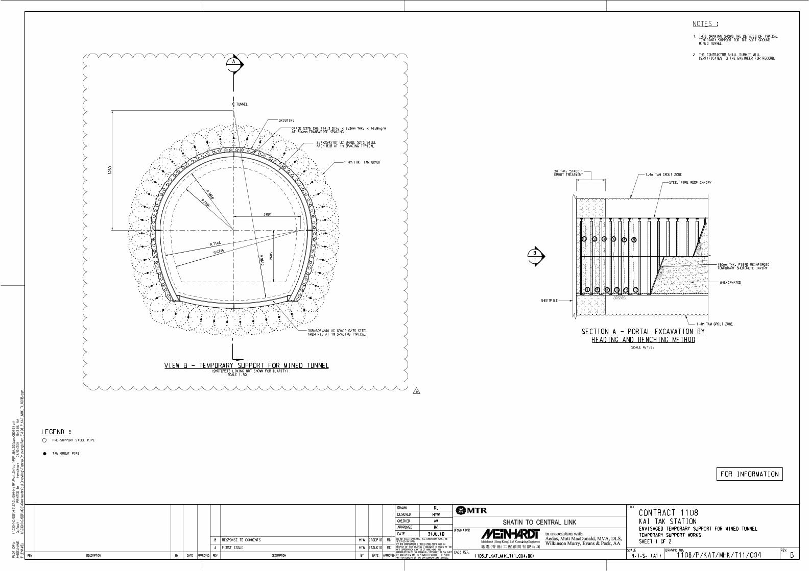
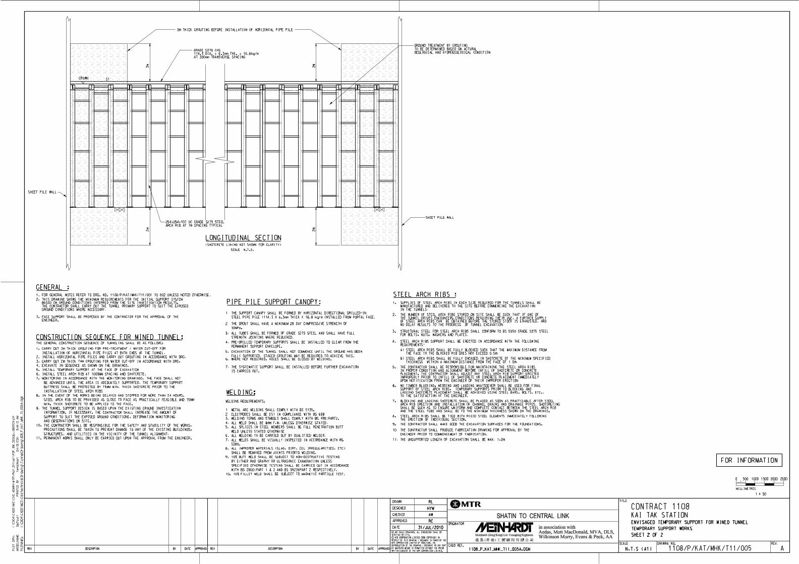
In order not to disturb the FKCP, the tunnel face is excavated in stages under cover of
improved ground condition by jack-grouting and horizontal canopy tube. The exposed
ground will supported by steel arches and sprayed concrete. Each excavation stage
(1.5m typically) is coordinated to ensure movements in the tunnel and at surrounding
ground surface are within the limit. This method will be adopted for the critical tunnel
section and length of about 40m.
The advantages of mined tunnel with horizontal canopy tube + grouting method are:
� The working area for tunnelling is minimized and therefore minimizes the possibility
of disturbance to the FKCP.
� The grout curtain for the mined tunnel construction can act as a kind of soil
stabilization and hence enhance the deflection control on FKCP.
� Minimize the risk on excavation sequence. The construction of the mined tunnel
(excluded the temporary ELS works) is approximate 6 to 8 months to ensure the
unsupported excavation length for each cycle is control within 1.5m.
The construction sequence of mined tunnel is attached in Appendix G.
The construction of mined tunnel at both ends is not recommended as the following
consideration:
� Learning period during the initial construction stage is double and is not economic
for short length of tunnelling.
� The excavation length will be shorten (0.75m at both ends) to minimize the risk of
construction. The construction time for the mined tunnel is more or less the same
as if construction from one end.
Reference is made to the pervious submitted working paper from AECOM – Shatin to
Central Link Tai Wai to Hung Hom Section WP CE21 Preservation of Lung Tsun Stone
Bridge dated March 2010.

Shatin to Central Link Consultancy Agreement No.: C1104 Detailed Design for Kai Tak Station and Associated Tunnels
6
consulting engineers • planners • managerswww.meinhardtgroup.com
4.0 CONCLUSIONS Based on the results of PIT carried out on 4 November 2010 and the latest proposed design of the development, several conclusions are made as follow:
From the results of PIT carried out on 4 November 2010 by Geotechnics & Concrete Engineering (H.K.) Limited, the length of the concrete pillars at the FKCP can not be confirmed.
The test result of TP8 on 4 November 2010 concurred with the results of PIT carried out on 25 August 2009, which found that the maximum length of the concrete pillars at the FKCP is about 9.0m to 9.5m. According to the ancient deep foundation technique at 1930’s and the relatively light weight structure of FKCP, the 9.5m pile length as tested is sufficient to support the FKCP.
The tunnel construction methods are fully considered the risk on the existing underground foundation system of FKCP. The proposed tunnel alignment is a well balanced option between the rail operational issues as well as minimizing the risk on FKCP.
The estimated clear zone range from 1.8m to 2.2m between the tip of existing piles and top of tunnel box which provide adequate buffer zone for the construction of mined tunnel.
Proper measures have been proposed to limit the influence to the FKCP. These include avoidance of at-grade works within buffer zones, shifting of tunnels alignments, lowering of tunnel profile, compensation grouting and geotechnical / structural monitoring system. It is considered that with these measures, all potential influence to the LTSB and FKCP due to the proposed tunnel construction will be limited and controlled.

Shatin to Central Link Consultancy Agreement No.: C1104 Detailed Design for Kai Tak Station and Associated Tunnels
consulting engineers • planners • managerswww.meinhardtgroup.com
Appendix A - Extracts of Test Report by Stangers Asia Limited in 2009


Shatin to Central Link Consultancy Agreement No.: C1104 Detailed Design for Kai Tak Station and Associated Tunnels
consulting engineers • planners • managerswww.meinhardtgroup.com
Appendix B - Location of Concrete Pillars under Pile Integrity Test on 4 Nov 2010

Concrete Pillars successfully tested on 4 Nov 2010

Shatin to Central Link Consultancy Agreement No.: C1104 Detailed Design for Kai Tak Station and Associated Tunnels
consulting engineers • planners • managerswww.meinhardtgroup.com
Appendix C - Results of Pile Integrity Test Carried Out on 4 Nov 2010


Shatin to Central Link Consultancy Agreement No.: C1104 Detailed Design for Kai Tak Station and Associated Tunnels
consulting engineers • planners • managerswww.meinhardtgroup.com
Appendix D - Tunnel Alignment (Preliminary Design and Current Proposal)


Horizontal distance betweenTunnel and LTSB increasedfrom 17m to 35.5m

Approximate Interface location betweenFKCP and proposed tunnels

LTSB & FKCB
Approximate Interface location betweenFKCP and proposed tunnels

Shatin to Central Link Consultancy Agreement No.: C1104 Detailed Design for Kai Tak Station and Associated Tunnels
consulting engineers • planners • managerswww.meinhardtgroup.com
Appendix E - Section Between Tunnel and FKCP

Buffer zone range from 1.8mto 2.2m between FKCP pilesand proposed tunnel
Estimated 9.5m pilezone of FKCP

Shatin to Central Link Consultancy Agreement No.: C1104 Detailed Design for Kai Tak Station and Associated Tunnels
consulting engineers • planners • managerswww.meinhardtgroup.com
Appendix F - Ground Monitoring Points around FKCP


Shatin to Central Link Consultancy Agreement No.: C1104 Detailed Design for Kai Tak Station and Associated Tunnels
consulting engineers • planners • managerswww.meinhardtgroup.com
Appendix G - Construction Sequence of Mined Tunnel under FKCP Site