shear and buckling resistance of … forms of wind bracing, ... showed inadequate buckling...
TRANSCRIPT
SHEAR AND BUCKLING RESISTANCE OFCLADDING MATERIALS USED AS
STRUCTURAL DIAPHRAGMS IN FARMBUILDINGS
J.E. Turnbull
Member CSAE
Engineering Research ServiceResearch Branch, Agriculture Canada
Ottawa, Ontario K1A 0C6
S.M. Guertin
Member CSAE
C.P. 900, R.R. No. 2St. Hyacinthe, Quebec
INTRODUCTION
Structural diaphragms are used widelyto stiffen and brace farm buildings,particularly insulated buildings havingboth exterior and interior claddings. Here,diaphragms are often the most suitablemeans of resisting the horizontal components of wind force. The critical farmbuilding design problem is usually windthat blows perpendicular to the long wallsas in Figure 1.
Alternative forms of wind bracing,such as knee bracing from the walls to theroof trusses, are often employed. Kneebracing is particularly unsuitablefor buildings where walking passages arelocated next to the outside walls; here theopen rectangular box made possible byceiling and endwall diaphragms is a muchbetter alternative. There are practicallimitations to the length/breadth ratio ofa ceiling used as a structural diaphragm,but the great majority of insulated farmbuildings are proportioned within theselimitations.
Wind forces for design of mostbuilding shapes, including typical gable-roofed farm buildings, can be estimatedfrom the Canadian Structural DesignManual (2). Basic principles for design offir plywood diaphragms are outlined in atechnical bulletin21, and Turnbullb furtherdeveloped these principles as applied totypical Canadian farm buildings.
Hammil (4) tested plywood-sheatheddiaphragms to evaluate nailed fastenings,
Contribution No. 370, from EngineeringResearch Service, Research Branch, AgricultureCanada, Ottawa, Ontario K1A 0C6.
RECEIVED FOR PUBLICATION NOVEMBER15,1973
shear strength and buckling failure ofplywood at various wall stud spacings.Nominal four-edge panel support spacingsevaluated in these tests were 48 X 96
inches (122 X 244 cm), 24 X 96 inches(61 X 244 cm), 16 X 96 inches (41 X 244cm), and 48 X 48 inches (122 X 122 cm).Plywoods 7/16 inch (11 mm) and 3/8inch (9.5 mm) thick were used inHammil's buckling-shear tests, but the5/16-inch (8-mm) thickness now usedextensively in Canadian farm buildingswas not included.
CSA Standard 086-1970 (3) givesallowable unit stresses for Douglas Firplywood, and a technical bulletin0 givesdimensional characteristics of variousgrades and thicknesses to determineallowable shear forces etc. for diaphragmdesign.
Obviously, plywood is not the onlycladding material used for farm buildings,but the literature contained little information on diaphragm properties of otherfarm-type claddings such as aspenflakeboard or sheet metals. Unpublishedpreliminary tests by Turnbull indicatedthat aluminum claddings in the thicknesses usually used for farm buildingsshowed inadequate buckling resistancefor most diaphragm requirements, soaluminum was not included in this series.
a Council of the Forest Industries of B.C.1968. Fir plywood diaphragms. Bull.64-112.
b Turnbull, J.E. 1971. Procedure for design ofplywood diaphragm ceilings for farm buildings. Contrib. No. 459, Eng. Res. Service,Can. Dep. Agric, Ottawa, Ont. K1A 0C6.
c Council of the Forest Industries of B.C.1967. Fir plywood design fundamentalsand physical properties. Bull. 66-137.
CANADIAN AGRICULTURAL ENGINEERING, VOL. 17 NO. 1, JUNE 1975
PROCEDURE
Based on Hammil (4), a test rig wasdesigned to apply compression loadsdiagonally across a lumber frame sized totake one 48 X 96-inch (122 X 244-cm)panel of wood-based cladding or one32 X 96-inch (81 X 244-cm) metal roofing sheet.
See Figure 3 for details of the test rig.All test specimens were designed to givefour-edge support to the cladding, andthe spacings of intermediate membersacross the sheets were based on the
popular truss spacings of 4 ft (122 cm)(see Figure 2), and 2 ft (61 cm). Panel
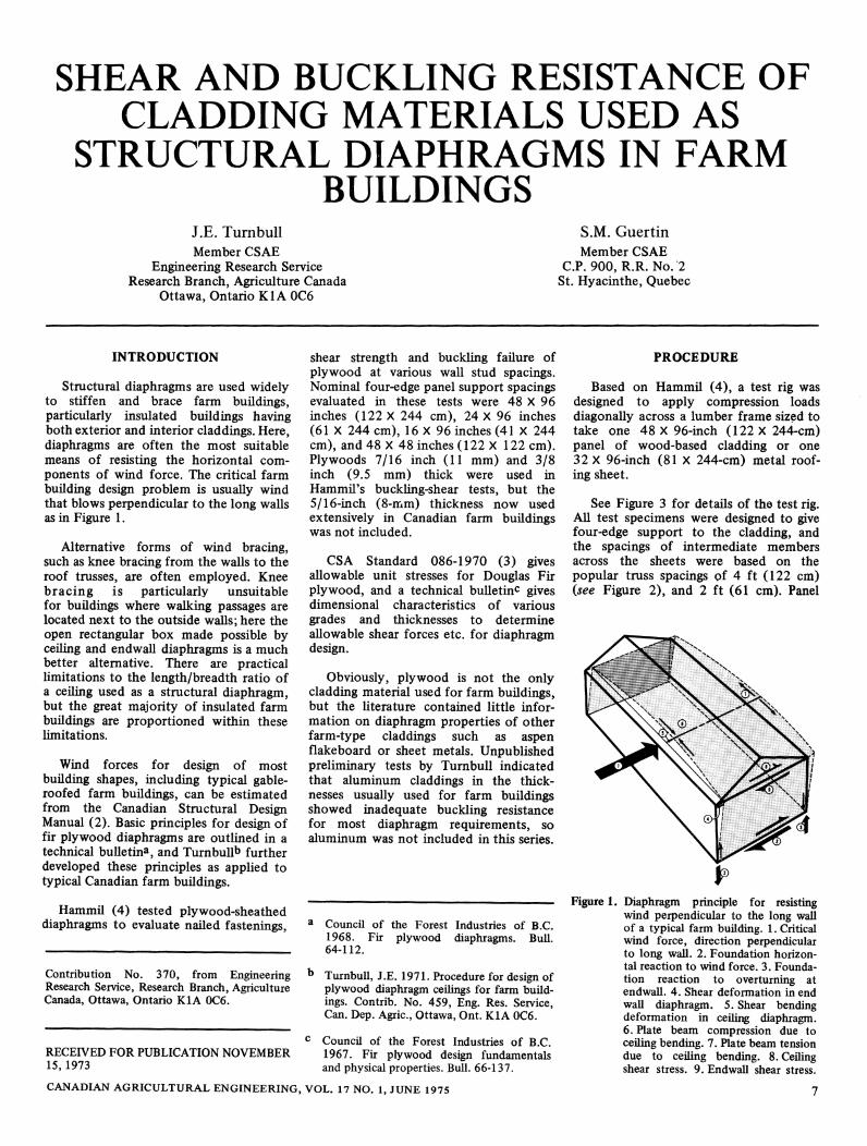
Figure 1. Diaphragm principle for resistingwind perpendicular to the long wallof a typical farm building. 1. Criticalwind force, direction perpendicularto long wall. 2. Foundation horizontal reaction to wind force. 3. Foundation reaction to overturning atendwall. 4. Shear deformation in endwall diaphragm. 5. Shear bendingdeformation in ceiling diaphragm.6. Plate beam compression due toceiling bending. 7. Plate beam tensiondue to ceiling bending. 8. Ceilingshear stress. 9. Endwall shear stress.

Figure 2. Typical connections for a ceiling-endwall diaphragm system, stud wall construction.1. Trusses 122 cm (4 ft) on center. 2.3.8-cm (1-1/2-inch) strapping. 3. Cross-blocking at122 cm (4 ft) on center both ways. 4. Ceiling sheathing nailed all 4 edges, end jointsstaggered 122 cm (4 ft). 5. Sidewall plate beam nailed continuous to resist plate beamtension due to ceiling bending moment. 6. Endwall plate beam nailed to transmit ceilingshear to endwall sheathing 7.7. Endwall sheathing nailed all 4 edges to transmit ceilingshear from plate beam 6 to sill 8. 8. Treated wood sill bolted to transmit shear and upliftto foundation 9.
edges were nailed to the 4 X 6-inch(9 X 14-cm) Douglas Fir test frame with1-1/2-inch (38.1-mm) X 10-gauge(3.43-mm) large head galvanized roofingnails. Perimeter nail spacings were calculated to guarantee failure of thecladdings, requiring a very close spacingto adequately load the stronger claddingmaterials.
Since Douglas Fir plywood has beenfully investigated for diaphragm properties, 5/16-inch (8-mm) 'select sheathing'grade was used as a control.
As a basic comparison, a working shearload of 65.6 lb/inch of panel width wascalculated from the allowable unit shearstress of 210 lb/inch2 as tabulated in CSA086(3).
This 5/16 inch control plywood wasnailed to the test frame at the nominal
support spacing of 24 X 48 inches(61 X 122 cm) (five replicates) andcompared with 48 X 48-inch(122 X 122-cm) support spacing, and3/8-inch (9.5-mm) Fir plywood, 5/16-inch (8-mm) Spruce plywood and 3/8-inch (9.5-mm) unsanded Asperated, all on48 X 48-inch (122 X 122-cm) grid spacings.
Galvanized steel roofing tests were alsoincluded but the support frames werealtered to accommodate a 36 X 96-inch
Registered trademark of MacMillan BloedelLtd., for 'mat-formed particle board, type1', described in CSA Standard 0188-1968.
(91.4 X 244-cm) roofing sheet which,when rolled into corrugated roofing,covered a nominal width of 32 inches
(81.3 cm). Steel thicknesses tested were30 gauge (0.305 mm, minimum thicknessbefore galvanizing), and 28 gauge (0.378mm) with 1.25 oz/ft2 (381 g/m2) zinccoating. These correspond to two popularfarm roofing thicknesses used in Canada.The corrugation pattern was a typicalfarm roofing profilee with major ribsspaced at 8-inch (20.3-cm) and 0.4-inch(1-cm) depths, similar to Figure 1-M,Canadian Code for Farm Buildings 1970(1). Each test was replicated five times.Specimens were loaded diagonally with ahand-operated hydraulic jack and loadingjig (Figure 3). Loads were measured witha 25,000-lb (111-kN) Universal load cellat the corner opposite the hydrauliccylinder. The load cell was wired to aDaytronic amplifier and a digital readoutsystem.
Panel deformations were recorded in
inches as read from the dial indicator and
these were converted to diagonal strain asfollows (see Figure 4):
G 101.75 (for wood panels) (1)
D
94.5 (for steel panels) (2)
where
SD
G
diagonal strain (inches/inch)panel diagonal deformation (inches)diagonal gauge distance across test panel(inches)
RESULTS
Data Interpretation
A linear regression on the controlplywood tests between load limits of2,000 to 10,000 lb (7=20.4 to 102.0lb/inch of panel width) gave the following:
K = 48,106 5 + 22.80 (3)
Taking V = 65.5 lb/inch (the shearload per unit panel width correspondingto the allowable unit shear stress for5/16-inch fir plywood control), equation(3) gives S = 0.000890 inch/inch. Forcomparison, test shear loads V for allother materials were interpolated aboutS = 0.000890 inch/inch (see Figure 5).From this the mean shear load V for each
material was calculated to indicate'comparative shear load' (Table I).
Westeel-Rosco Ltd.,Toronto, Ontario.
1 Atlantic Ave.,
CANADIAN AGRICULTURAL ENGINEERING, VOL. 17 NO. 1, JUNE 1975
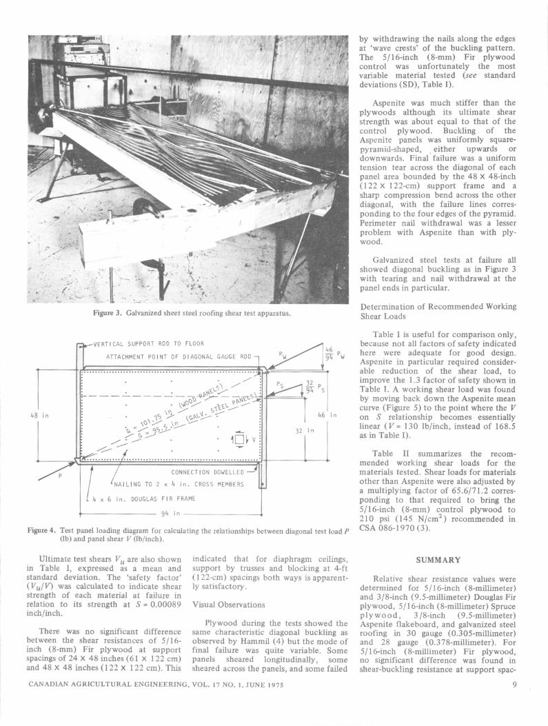
Figure 3. Galvanized sheet steel roofing shear test apparatus.
-VERTICAL SUPPORT ROD TO FLOOR
ATTACHMENT POINT OF DIAGONAL GAUGE ROD
^°
32
*?:.. ±
-NAILING TO 2
CONNECTION DOWELLED
h in. CROSS MEMBERS
DOUGLAS FIR FRAME
9<)
Figure 4. Test panel loading diagram for calculating the relationships between diagonal test load P(lb) and panel shear V (lb/inch).
Ultimate test shears Vu are also shownin Table I, expressed as a mean andstandard deviation. The 'safety factor'(Vu/V) was calculated to indicate shearstrength of each material at failure inrelation to its strength at S = 0.00089inch/inch.
There was no significant differencebetween the shear resistances of 5/16-inch (8-mm) Fir plywood at supportspacings of 24 X 48 inches (61 X 122 cm)and 48 X 48 inches (122 X 122 cm). This
indicated that for diaphragm ceilings,support by trusses and blocking at 4-ft(122-cm) spacings both ways is apparently satisfactory.
Visual Observations
Plywood during the tests showed thesame characteristic diagonal buckling asobserved by Hammil (4) but the mode offinal failure was quite variable. Somepanels sheared longitudinally, somesheared across the panels, and some failed
CANADIAN AGRICULTURAL ENGINEERING, VOL. 17 NO. 1, JUNE 197S
by withdrawing the nails along the edgesat 'wave crests' of the buckling pattern.The 5/16-inch (8-mm) Fir plywoodcontrol was unfortunately the mostvariable material tested (see standarddeviations (SD), Table I).
Aspenite was much stiffer than theplywoods although its ultimate shearstrength was about equal to that of thecontrol plywood. Buckling of theAspenite panels was uniformly square-pyramid-shaped, either upwards ordownwards. Final failure was a uniform
tension tear across the diagonal of eachpanel area bounded by the 48 X 48-inch(122 X 122-cm) support frame and asharp compression bend across the otherdiagonal, with the failure lines corresponding to the four edges of the pyramid.Perimeter nail withdrawal was a lesser
problem with Aspenite than with plywood.
Galvanized steel tests at failure all
showed diagonal buckling as in Figure 3with tearing and nail withdrawal at thepanel ends in particular.
Determination of Recommended WorkingShear Loads
Table I is useful for comparison only,because not all factors of safety indicatedhere were adequate for good design.Aspenite in particular required considerable reduction of the shear load, toimprove the 1.3 factor of safety shown inTable I. A working shear load was foundby moving back down the Aspenite meancurve (Figure 5) to the point where the Von S relationship becomes essentiallylinear (V = 130 lb/inch, instead of 168.5as in Table I).
Table II summarizes the recom
mended working shear loads for thematerials tested. Shear loads for materials
other than Aspenite were also adjusted bya multiplying factor of 65.6/71.2 corresponding to that required to bring the5/16-inch (8-mm) control plywood to210 psi (145 N/cm"CSA 086-1970 (3).
) recommended in
SUMMARY
Relative shear resistance values were
determined for 5/16-inch (8-millimeter)and 3/8-inch (9.5-millimeter) Douglas Firplywood, 5/16-inch (8-millimeter) Spruceplywood, 3/8-inch (9.5-millimeter)Aspenite flakeboard, and galvanized steelroofing in 30 gauge (0.305-millimeter)and 28 gauge (0.378-millimeter). For5/16-inch (8-millimeter) Fir plywood,no significant difference was found inshear-buckling resistance at support spac-
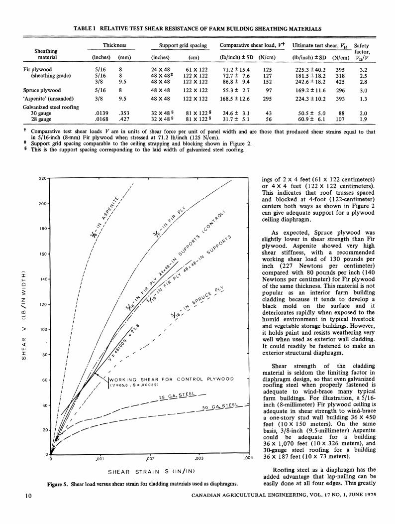
TABLE I RELATIVE TEST SHEAR RESISTANCE OF FARM BUILDING SHEATHING MATERIALS
Thickness Support grid spacing
(inches) (cm)
Comparative shear load, V*
(lb/inch) ±SD (N/cm)
Ultimate test shear, Vu
(lb/inch) ± SD (N/cm)
SafetySheathing
material (inches) (mm)factor,VJV
Fir plywood(sheathing grade)
5/165/163/8
8
8
9.5
24X48
48X48*48X48
61 X 122
122 X 122
122 X 122
71.2 ±15.4
72.7 ± 7.686.8 ± 9.4
125
127
152
225.3 ±40.2
181.5 ±18.2242.6 ± 18.2
395
318
425
3.2
2.5
2.8
Spruce plywood 5/16 8 48X48 122 X 122 55.3 ± 2.7 97 169.2 ±11.6 296 3.0
'Aspenite' (unsanded) 3/8 9.5 48X48 122 X 122 168.5 ± 12.6 295 224.3 ±10.2 393 1.3
Galvanized steel roofing30 gauge28 gauge
.0139
.0168
.353
.427
32 X 48 §32 X 48 §
81X122§81 X122§
24.6 ± 3.131.7 ± 5.1
43
56
50.5 ± 5.060.9± 6.1
88
107
2.0
1.9
* Comparative test shear loads V are in units of shear force per unit of panel width and are those that produced shear strains equal to thatin 5/16-inch (8-mm) Fir plywood when stressed at 71.2 lb/inch (125 N/cm).
* Support grid spacing comparable to the ceiling strapping and blocking shown in Figure 2.§ This is the support spacing corresponding to the laid width of galvanized steel roofing.
x
h-
Q
5Z
\
CO
OT
<LU
I
CO
10
220-
200-
180
160-
140
120 -
PLYWOOD
STEEL__ JL
SHEAR STRAIN S (IN/IN)
Figure 5. Shear load versusshearstrain for cladding materials used as diaphragms.
.004
ings of 2 X 4 feet (61 X 122 centimeters)or 4X4 feet (122 X 122 centimeters).This indicates that roof trusses spacedand blocked at 4-foot (122-centimeter)centers both ways as shown in Figure 2can give adequate support for a plywoodceiling diaphragm.
As expected, Spruce plywood wasslightly lower in shear strength than Firplywood. Aspenite showed very highshear stiffness, with a recommendedworking shear load of 130 pounds perinch (227 Newtons per centimeter)compared with 80 pounds per inch (140Newtons per centimeter) for Fir plywoodof the same thickness. This material is not
popular as an interior farm buildingcladding because it tends to develop ablack mold on the surface and it
deteriorates rapidly when exposed to thehumid environment in typical livestockand vegetable storage buildings. However,it holds paint and resists weathering verywell when used as exterior wall cladding.It could readily be fastened to make anexterior structural diaphragm.
Shear strength of the claddingmaterial is seldom the limiting factor indiaphragm design, so that even galvanizedroofing steel when properly fastened isadequate to wind-brace many typicalfarm buildings. For illustration, a 5/16-inch (8-millimeter) Fir plywood ceiling isadequate in shear strength to wind-bracea one-story stud wall building 36 X 450feet (10 X 150 meters). On the samebasis, 3/8-inch (9.5-millimeter) Aspenitecould be adequate for a building36 X 1,070 feet (10 X 326 meters), and30-gauge steel roofing for a building36 X 187 feet (10 X 73 meters).
Roofing steel as a diaphragm has theadded advantage that lap-nailing can beeasily done at all four edges. This greatly
CANADIAN AGRICULTURAL ENGINEERING, VOL. 17 NO. 1, JUNE 1975
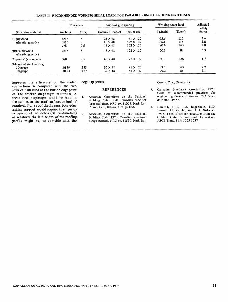
TABLE II RECOMMENDED WORKING SHEAR LOADS FOR FARM BUILDING SHEATHING MATERIALS
Thickness Support grid spacing Working shear load
(lb/inch) (N/cm)
Adjusted
Sheathing material (inches) (mm) (inches X inches) (cm X cm)safetyfactor
Fir plywood(sheathing grade)
5/165/163/8
8
8
9.5
24X48
48X48
48X48
61 X 122
122 X 122
122 X 122
65.6
65.6
80.0
115
115
140
3.4
2.8
3.0
Spruce plywood(sheathing grade)
5/16 8 48X48 122X122 50.9 89 3.3
'Aspenite' (unsanded) 3/8 9.5 48X48 122 X 122 130 228 1.7
Galvanized steel roofing30 gauge28 gauge .
.0139
.0168
.353
.427
32X48
32X48
81 X 122
81 X 122
22.7
29.2
40
51
2.2
2.1
improves the efficiencyconnections as comparedrows of nails used at the bi
of the nailed
with the two
itted edge joint
edge lap joints.
REFERENCES
Counc. Can., Ottawa,
3. Canadian Standards
Ont.
Association. 1970.
Code of recommended practices forengineering design in timber. CSA Standard 086, 49-52.
Hammil, H.B., H.J. Degenkolb, H.D.Dewell, J.J. Gould, and L.H. Nishkian.1948. Tests of timber structures from the
Golden Gate International Exposition.ASCE Trans. 113: 1223-1237.
of the thicker diaphragm materials. Asheet steel diaphragm could be built atthe ceiling, at the roof surface, or both ifrequired. For a roof diaphragm, four-edgenailing support would require that trussesbe spaced at 32 inches (81 centimeters)or whatever the laid width of the roofingprofile might be, to coincide with the
2.
Associate Committee on the NationalBuilding Code. 1970. Canadian code forfarm buildings. NRC no. 11065, Natl. Res.Counc. Can., Ottawa, Ont. p. 182. 4.
Associate Committee on the NationalBuilding Code. 1970. Canadian structuraldesign manual. NRC no. 11530, Natl. Res.
CANADIAN AGRICULTURAL ENGINEERING, VOL. 17 NO. 1, JUNE 1975 11