shell catalysts & technologies capturing value through
TRANSCRIPT
Shell Catalysts & Technologies
CAPTURING VALUE THROUGH INTEGRATED IMPROVEMENTS AT THE FCC-PT–FCC COMPLEXWHITE PAPER DECEMBER 2019
FCC-PTCATALYSTS
LICENSED TECHNOLOGIES
ADVANCED MODELLING
CONTENTS
1. Introduction: The importance of FCC-PT–FCC unit integration
2. How the FCC-PT unit improves feed quality to the FCC unit
3. Our offer
4. FCC-PT catalysts
5. Licensed FCC unit hardware
6. Advanced modelling to drive technology improvements
7. Proof points
8. Future opportunities
9. Key takeaways
About the authors
3
4
6
7
12
14
16
17
18
19
HAVE YOU EVER… improved the performance of your FCC-PT unit but failed to achieve a consequent benefit in the FCC unit’s performance?
taken the constraints in the FCC heat balance and product recovery section into consideration when developing FCC-PT catalyst design and operation?
declined a high-margin opportunity feed because you were unsure what impact it would have on your FCC-PT–FCC complex operations and reliability?
processed difficult feeds in your FCC unit to improve your profitability only to find that the consequent impacts on FCC yields, catalyst usage and emissions outweigh the margin benefits?
If so, there may be an opportunity for you to improve the integration of your FCC-PT and FCC units and benefit from: improved profitability for the overall refinery; longer unit cycle lives; and greater complex flexibility and reliability.
Shell Catalysts & Technologies
3
SHELL’S FCC-PT AND FCC CREDENTIALSThe Shell Group has unparalleled FCC-PT and FCC experience spanning more than 70 years as an owner, operator and licensor.
Shell Catalysts & Technologies provides leading-edge FCC-PT catalysts, reactor internals and catalysts, as well as FCC hardware, modelling and services, to Shell and non-Shell refineries around the world.
As an owner–operator, Shell has had: 1,300 unit years of FCC operational experience; more than 350 FCC shutdown periods that have provided continuous lessons learned and
design improvements; and more than 70 years of research and development expertise.
As a licensor, Shell has delivered: 33 grass-roots FCC unit designs; more than 65 revamps since 1980; and over 75 third-stage separator installations since 1969.
1. INTRODUCTION: THE IMPORTANCE OF FCC-PT–FCC UNIT INTEGRATIONAs they strive to remain competitive in the face of changing market dynamics, many refiners are looking for ways to extract even more value from their units. However, as the pressure on margins and utilisation intensifies, it is no longer enough for technologists to consider their units in isolation, especially when it comes to the fluidised catalytic cracking pretreatment (FCC-PT) and fluidised catalytic cracking (FCC) units.
Although these units are often in different operating groups, have different hardware, experience different issues and require different expertise, there is growing realisation across the industry that they should be considered as an integrated complex. This is because the quality of the feeds the FCC-PT unit provides can have a major impact on the performance of the FCC unit. It affects the FCC unit’s coking tendency and feed crackability and conversion; removes metals poisons such as nickel (Ni) and vanadium (V) from the feed; and reduces the sulphur oxide emissions from both the FCC regenerator and the product slate.
Consequently, by running these two units as a single, optimised operation, operators can improve the overall refinery’s profitability, extend their units’ cycle lives and improve their reliability.
In this white paper, we examine some of the key aspects to consider.
Shell Catalysts & Technologies
4
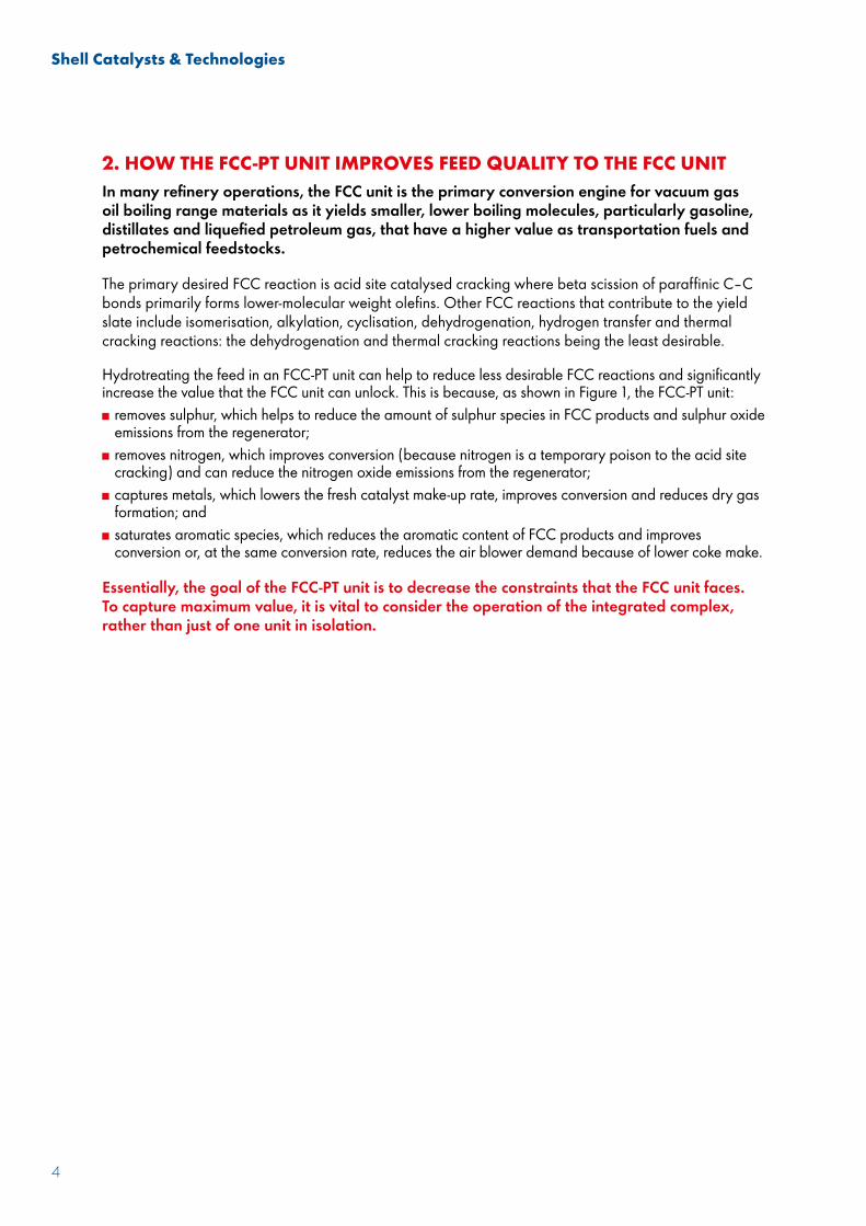
2. HOW THE FCC-PT UNIT IMPROVES FEED QUALITY TO THE FCC UNIT In many refinery operations, the FCC unit is the primary conversion engine for vacuum gas oil boiling range materials as it yields smaller, lower boiling molecules, particularly gasoline, distillates and liquefied petroleum gas, that have a higher value as transportation fuels and petrochemical feedstocks.
The primary desired FCC reaction is acid site catalysed cracking where beta scission of paraffinic C–C bonds primarily forms lower-molecular weight olefins. Other FCC reactions that contribute to the yield slate include isomerisation, alkylation, cyclisation, dehydrogenation, hydrogen transfer and thermal cracking reactions: the dehydrogenation and thermal cracking reactions being the least desirable.
Hydrotreating the feed in an FCC-PT unit can help to reduce less desirable FCC reactions and significantly increase the value that the FCC unit can unlock. This is because, as shown in Figure 1, the FCC-PT unit: removes sulphur, which helps to reduce the amount of sulphur species in FCC products and sulphur oxide emissions from the regenerator;
removes nitrogen, which improves conversion (because nitrogen is a temporary poison to the acid site cracking) and can reduce the nitrogen oxide emissions from the regenerator;
captures metals, which lowers the fresh catalyst make-up rate, improves conversion and reduces dry gas formation; and
saturates aromatic species, which reduces the aromatic content of FCC products and improves conversion or, at the same conversion rate, reduces the air blower demand because of lower coke make.
Essentially, the goal of the FCC-PT unit is to decrease the constraints that the FCC unit faces. To capture maximum value, it is vital to consider the operation of the integrated complex, rather than just of one unit in isolation.

Shell Catalysts & Technologies
5
Figure 1: FCC-PT–FCC: The interaction.
Emissions
Contaminantreduction
S N ACoke
C AFlue gas
REGENERATOR
Regen. temperature
Catalyst make-up
MAIR BLOWER
REACTOR
FCC-PT
RISER
FRACTIONATOR
Air
Steam
FCC-PT feed
Hydrotreated FCC feed
Reactor temperature
Conversion
N C A
Dry gas production
M ALPG production
N A
API of LCO + products
N A
Sulphur of products
S N ACatalyst circulation
C A
Feed
Sulphur
THE OPTIMISATION PATHThe optimisation path for the FCC-PT–FCC complex should consider the operator’s specific performance objectives. These include various environmental and operational constraints, yield economics, cycle life and reliability measures, and can vary significantly from site to site.
Because of the complex mix of environmental, operational and economic drivers, understanding the impact that feed quality changes can have on these objectives is key.
Shell Catalysts & Technologies
6
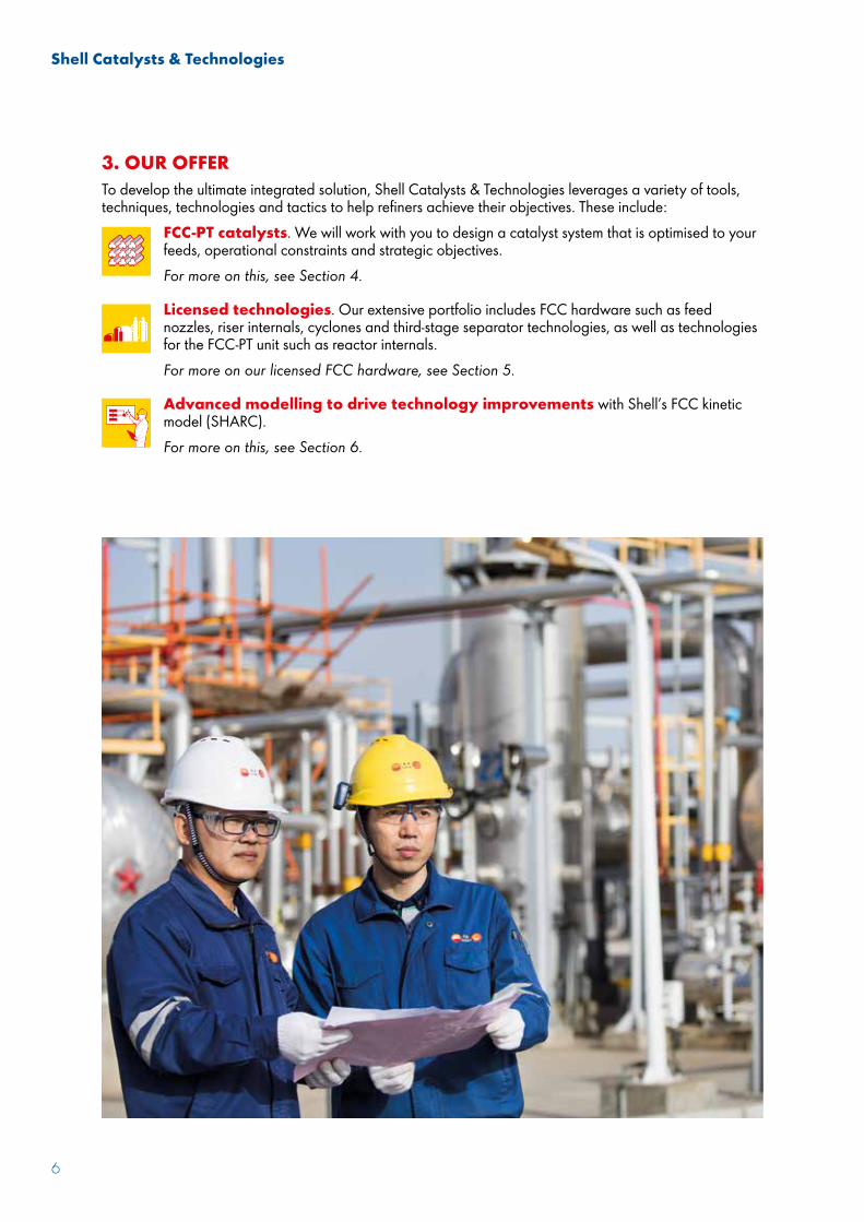
3. OUR OFFERTo develop the ultimate integrated solution, Shell Catalysts & Technologies leverages a variety of tools, techniques, technologies and tactics to help refiners achieve their objectives. These include:
FCC-PT catalysts. We will work with you to design a catalyst system that is optimised to your feeds, operational constraints and strategic objectives.For more on this, see Section 4.
Licensed technologies. Our extensive portfolio includes FCC hardware such as feed nozzles, riser internals, cyclones and third-stage separator technologies, as well as technologies for the FCC-PT unit such as reactor internals.For more on our licensed FCC hardware, see Section 5.
Advanced modelling to drive technology improvements with Shell’s FCC kinetic model (SHARC).For more on this, see Section 6.
Shell Catalysts & Technologies
7
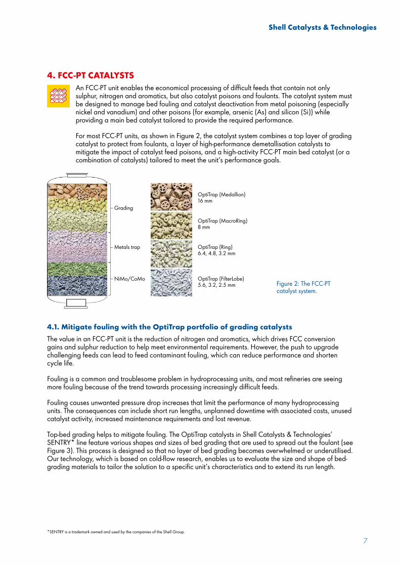
4. FCC-PT CATALYSTSAn FCC-PT unit enables the economical processing of difficult feeds that contain not only sulphur, nitrogen and aromatics, but also catalyst poisons and foulants. The catalyst system must be designed to manage bed fouling and catalyst deactivation from metal poisoning (especially nickel and vanadium) and other poisons (for example, arsenic (As) and silicon (Si)) while providing a main bed catalyst tailored to provide the required performance.
For most FCC-PT units, as shown in Figure 2, the catalyst system combines a top layer of grading catalyst to protect from foulants, a layer of high-performance demetallisation catalysts to mitigate the impact of catalyst feed poisons, and a high-activity FCC-PT main bed catalyst (or a combination of catalysts) tailored to meet the unit’s performance goals.
Figure 2: The FCC-PT catalyst system.
4.1. Mitigate fouling with the OptiTrap portfolio of grading catalystsThe value in an FCC-PT unit is the reduction of nitrogen and aromatics, which drives FCC conversion gains and sulphur reduction to help meet environmental requirements. However, the push to upgrade challenging feeds can lead to feed contaminant fouling, which can reduce performance and shorten cycle life.
Fouling is a common and troublesome problem in hydroprocessing units, and most refineries are seeing more fouling because of the trend towards processing increasingly difficult feeds.
Fouling causes unwanted pressure drop increases that limit the performance of many hydroprocessing units. The consequences can include short run lengths, unplanned downtime with associated costs, unused catalyst activity, increased maintenance requirements and lost revenue.
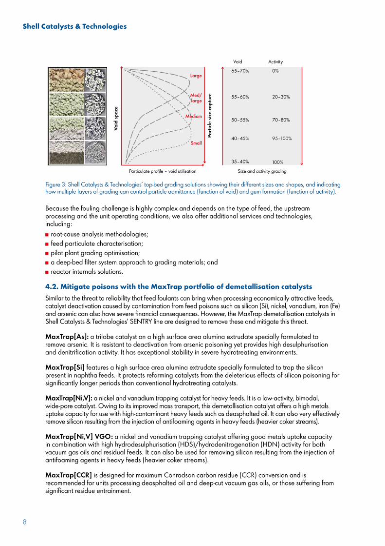
Top-bed grading helps to mitigate fouling. The OptiTrap catalysts in Shell Catalysts & Technologies’ SENTRY* line feature various shapes and sizes of bed grading that are used to spread out the foulant (see Figure 3). This process is designed so that no layer of bed grading becomes overwhelmed or underutilised. Our technology, which is based on cold-flow research, enables us to evaluate the size and shape of bed-grading materials to tailor the solution to a specific unit’s characteristics and to extend its run length.
Grading
OptiTrap (Medallion)16 mm
OptiTrap (MacroRing)8 mm
OptiTrap (Ring)6.4, 4.8, 3.2 mm
OptiTrap (FilterLobe)5.6, 3.2, 2.5 mm
Metals trap
NiMo/CoMo
*SENTRY is a trademark owned and used by the companies of the Shell Group.
Shell Catalysts & Technologies
8
Because the fouling challenge is highly complex and depends on the type of feed, the upstream processing and the unit operating conditions, we also offer additional services and technologies, including: root-cause analysis methodologies; feed particulate characterisation; pilot plant grading optimisation; a deep-bed filter system approach to grading materials; and reactor internals solutions.
4.2. Mitigate poisons with the MaxTrap portfolio of demetallisation catalystsSimilar to the threat to reliability that feed foulants can bring when processing economically attractive feeds, catalyst deactivation caused by contamination from feed poisons such as silicon (Si), nickel, vanadium, iron (Fe) and arsenic can also have severe financial consequences. However, the MaxTrap demetallisation catalysts in Shell Catalysts & Technologies’ SENTRY line are designed to remove these and mitigate this threat.
MaxTrap[As]: a trilobe catalyst on a high surface area alumina extrudate specially formulated to remove arsenic. It is resistant to deactivation from arsenic poisoning yet provides high desulphurisation and denitrification activity. It has exceptional stability in severe hydrotreating environments.
MaxTrap[Si] features a high surface area alumina extrudate specially formulated to trap the silicon present in naphtha feeds. It protects reforming catalysts from the deleterious effects of silicon poisoning for significantly longer periods than conventional hydrotreating catalysts.
MaxTrap[Ni,V]: a nickel and vanadium trapping catalyst for heavy feeds. It is a low-activity, bimodal, wide-pore catalyst. Owing to its improved mass transport, this demetallisation catalyst offers a high metals uptake capacity for use with high-contaminant heavy feeds such as deasphalted oil. It can also very effectively remove silicon resulting from the injection of antifoaming agents in heavy feeds (heavier coker streams).
MaxTrap[Ni,V] VGO: a nickel and vanadium trapping catalyst offering good metals uptake capacity in combination with high hydrodesulphurisation (HDS)/hydrodenitrogenation (HDN) activity for both vacuum gas oils and residual feeds. It can also be used for removing silicon resulting from the injection of antifoaming agents in heavy feeds (heavier coker streams).
MaxTrap[CCR] is designed for maximum Conradson carbon residue (CCR) conversion and is recommended for units processing deasphalted oil and deep-cut vacuum gas oils, or those suffering from significant residue entrainment.
Figure 3: Shell Catalysts & Technologies’ top-bed grading solutions showing their different sizes and shapes, and indicating how multiple layers of grading can control particle admittance (function of void) and gum formation (function of activity).
Large
Particulate profile – void utilisation Size and activity grading
Void
65–70% 0%
20–30%
70–80%
95–100%
100%
55–60%
50–55%
40–45%
35–40%
Activity
Void
spa
ce
Part
icle
size
capt
ureMed/
large
Medium
Small
Shell Catalysts & Technologies
9
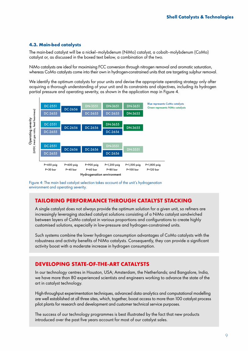
Figure 4: The main bed catalyst selection takes account of the unit’s hydrogenation environment and operating severity.
Hydrogenation environment
P=450 psig P=600 psig P=900 psig P=1,200 psig P=1,500 psig P=1,800 psigP=30 bar P=40 bar P=60 bar P=80 bar P=100 bar P=120 bar
Ope
ratin
g se
verit
y(L
HSV,
trea
t gas
ratio
, fee
d he
avin
ess)
Blue represents CoMo catalystsGreen represents NiMo catalysts
DC-2551
DC-2551
DC-2551
DC-2655 DC-2655 DC-2655
DC-2655
DC-2655
DC-2656DC-2656
DC-2656
DC-2656
DC-2656
DC-2656 DC-2656
DN-3551 DN-3651 DN-3651
DN-3655
DN-3655DN-3655
DN-3551DN-3551
TAILORING PERFORMANCE THROUGH CATALYST STACKINGA single catalyst does not always provide the optimum solution for a given unit, so refiners are increasingly leveraging stacked catalyst solutions consisting of a NiMo catalyst sandwiched between layers of CoMo catalyst in various proportions and configurations to create highly customised solutions, especially in low-pressure and hydrogen-constrained units.
Such systems combine the lower hydrogen consumption advantages of CoMo catalysts with the robustness and activity benefits of NiMo catalysts. Consequently, they can provide a significant activity boost with a moderate increase in hydrogen consumption.
DEVELOPING STATE-OF-THE-ART CATALYSTSIn our technology centres in Houston, USA; Amsterdam, the Netherlands; and Bangalore, India, we have more than 80 experienced scientists and engineers working to advance the state of the art in catalyst technology.
High-throughput experimentation techniques, advanced data analytics and computational modelling are well established at all three sites, which, together, boast access to more than 100 catalyst process pilot plants for research and development and customer technical service purposes.
The success of our technology programmes is best illustrated by the fact that new products introduced over the past five years account for most of our catalyst sales.
4.3. Main-bed catalystsThe main-bed catalyst will be a nickel–molybdenum (NiMo) catalyst, a cobalt–molybdenum (CoMo) catalyst or, as discussed in the boxed text below, a combination of the two.
NiMo catalysts are ideal for maximising FCC conversion through nitrogen removal and aromatic saturation, whereas CoMo catalysts come into their own in hydrogen-constrained units that are targeting sulphur removal.
We identify the optimum catalysts for your units and devise the appropriate operating strategy only after acquiring a thorough understanding of your unit and its constraints and objectives, including its hydrogen partial pressure and operating severity, as shown in the application map in Figure 4.

Shell Catalysts & Technologies
10
NiMo FCC-PT catalysts for maximising FCC conversion through nitrogen removal and aromatic saturationShell Catalysts & Technologies recently launched CENTERA* GT DN-3655, which builds on the extensive global success it has achieved with the ultra-stable ASCENT* and high-performance CENTERA products (Figure 5). CENTERA GT DN-3655 enhances both HDN and HDS performance while maintaining stability across a broad range of scenarios, particularly in high-severity applications that require maximum activity to process challenging feeds.
■ Proven exceptional stability■ Mixed Type I/Type II catalyst
■ Global success■ Broad application■ Type II catalyst
■ Highest activity■ Type 2 catalyst
Figure 5: The evolution of Shell Catalysts & Technologies’ NiMo catalysts.
Figure 6: The performance of CENTERA GT DN-3655 in medium- and high-pressure operations with challenging feedstocks.
As shown in Figure 6, depending on the feed and conditions, CENTERA GT DN-3655 can provide: HDN performance increases of more than 25%; HDS gains of up to 15%; and improved hydrogenation.
Canadian synthetic feed
HDN
Rela
tive
volu
met
ric a
ctiv
ity
HDS HDN HDS HDN HDS
US West Coast feed
US Gulf Coast feed160
+15ºF+8ºC +15ºF
+6ºC+9ºF+5ºC
+4ºF+2ºC
+13ºF+7ºC
140
120
100
80
+7ºF+4ºC
Shell Catalysts & Technologies
11
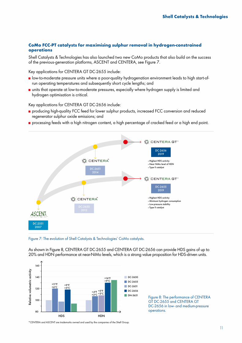
CoMo FCC-PT catalysts for maximising sulphur removal in hydrogen-constrained operationsShell Catalysts & Technologies has also launched two new CoMo products that also build on the success of the previous-generation platforms, ASCENT and CENTERA, see Figure 7.
Key applications for CENTERA GT DC-2655 include: low-to-moderate pressure units where a poor-quality hydrogenation environment leads to high start-of-run operating temperatures and subsequently short cycle lengths; and
units that operate at low-to-moderate pressures, especially where hydrogen supply is limited and hydrogen optimisation is critical.
Key applications for CENTERA GT DC-2656 include: producing high-quality FCC feed for lower sulphur products, increased FCC conversion and reduced regenerator sulphur oxide emissions; and
processing feeds with a high nitrogen content, a high percentage of cracked feed or a high end point.
As shown in Figure 8, CENTERA GT DC-2655 and CENTERA GT DC-2656 can provide HDS gains of up to 20% and HDN performance at near-NiMo levels, which is a strong value proposition for HDS-driven units.
■ Highest HDS activity■ Near NiMo level of HDN■ Type II catalyst
■ Highest HDS activity■ Minimum hydrogen consumption■ Low-pressure stability■ Type II catalyst
Figure 7: The evolution of Shell Catalysts & Technologies’ CoMo catalysts.
Figure 8: The performance of CENTERA GT DC-2655 and CENTERA GT DC-2656 in low- and medium-pressure operations.
Rela
tive
volu
met
ric a
ctiv
ity
120
140
80
100
160
HDS HDN
+11ºF+6ºC
+9ºF+5ºC
+4ºF+2ºC
+5ºF+3ºC
+16ºF+9ºC
*CENTERA and ASCENT are trademarks owned and used by the companies of the Shell Group.
Shell Catalysts & Technologies
12
5. LICENSED FCC HARDWAREAs shown in the highlighted sections in Figure 9, Shell Catalysts & Technologies offers licensed hardware solutions for much of the FCC unit. This includes our:
proprietary side and bottom-entry feed nozzles that offer excellent riser coverage and mixing with the catalyst. This can result in improved yields of light cycle oil, gasoline and liquefied petroleum gas through better bottoms upgrading; less dry gas; and lower steam consumption and pressure requirements.
riser internals, which improve catalyst distribution and reduce spent catalyst reflux. This minimises nonselective thermal cracking.
close-coupled reactor cyclones with vortex stabilisers and coke catchers. In addition to providing high separation efficiency and better reliability, these help to reduce post-riser cracking and reactor vessel coking.
proprietary PentaFlow stripper packing that removes up to 95% of hydrocarbons. The relatively open design avoids plugging, enhances catalyst flux and facilitates access for maintenance efforts.
catalyst circulation enhancement technology, which improves circulation rates by up to 50% and is applicable to both the stripper and the regenerator standpipes. This technology also improves stability and pressure build-up by optimising the catalyst condition near the inlets.
flue-gas technology such as our third-stage separator technology, which has been installed in more than 75 units over the past 50 years.

Shell Catalysts & Technologies
13
ExpanderHardware design
Main air blower
■ Air distributors■ Spent catalyst distributor ■ Catalyst circulation
enhancements ■ Strippers■ Cyclones■ Feed nozzles■ Riser internals■ Third-stage separator
Wet gas compressor
Shell’s FCC technologies are flexible and can be installed in many different unit configurations, including stacked and side-by-side units. Internal or external risers can be accommodated with designs for stripper internals, close-coupled cyclones or a riser termination device.
The spent catalyst inlet device can be either side entry or centrally located, and the third-stage separator can be in a separate vessel or, when there are plot constraints, integrated into the regenerator.
Figure 9: Shell Catalysts & Technologies’ licensed FCC hardware.

Shell Catalysts & Technologies
14
6. ADVANCED MODELLING TO DRIVE TECHNOLOGY IMPROVEMENTS Modelling is a key tool for FCC-PT–FCC unit integration because it can help to define the project scope by estimating the future performance gains of any proposed solution. To help with this, Shell uses and offers its own FCC kinetic model, SHARC, which was developed during years of research using data from about 50 refineries.
SHARC integrates with the online optimisation system and refinery planning and scheduling tools and can be used for: unit monitoring and data normalisation; studying economic and unit impacts of opportunity feeds; optimising unit operating conditions for yield improvements and margin gains; and evaluating additive use.
SHARC has been extensively validated against commercial FCCs with test data, and typically helps refiners to improve their profitability by $0.10–0.50 per barrel.
SHARC TYPICALLY HELPS REFINERS TO IMPROVE THEIR PROFITABILITY BY $0.10–0.50 PER BARREL.
Shell Catalysts & Technologies
15
DIAGNOSIS TOOLSBecause the goal is to optimise the performance of the overall, integrated FCC-PT–FCC complex, it is important to understand the impact that changes in one unit would have on the other.
To achieve this, we offer two proven diagnosis tools: the FCC constraints matrix and the FCC feed impact matrix, which help to facilitate the all-important cross-functional collaboration that is required.
PILOT PLANT, TROUBLESHOOTING AND TRAINING OFFERINGSIn addition to receiving state-of-the-art FCC-PT catalysts and technologies for the FCC-PT and FCC units, our customers can also benefit from technical support from our knowledgeable and experienced technologists, troubleshooting, training and access to cutting-edge facilities such as our riser pilot plants, which are used for testing feeds and catalysts.
Shell Catalysts & Technologies
16
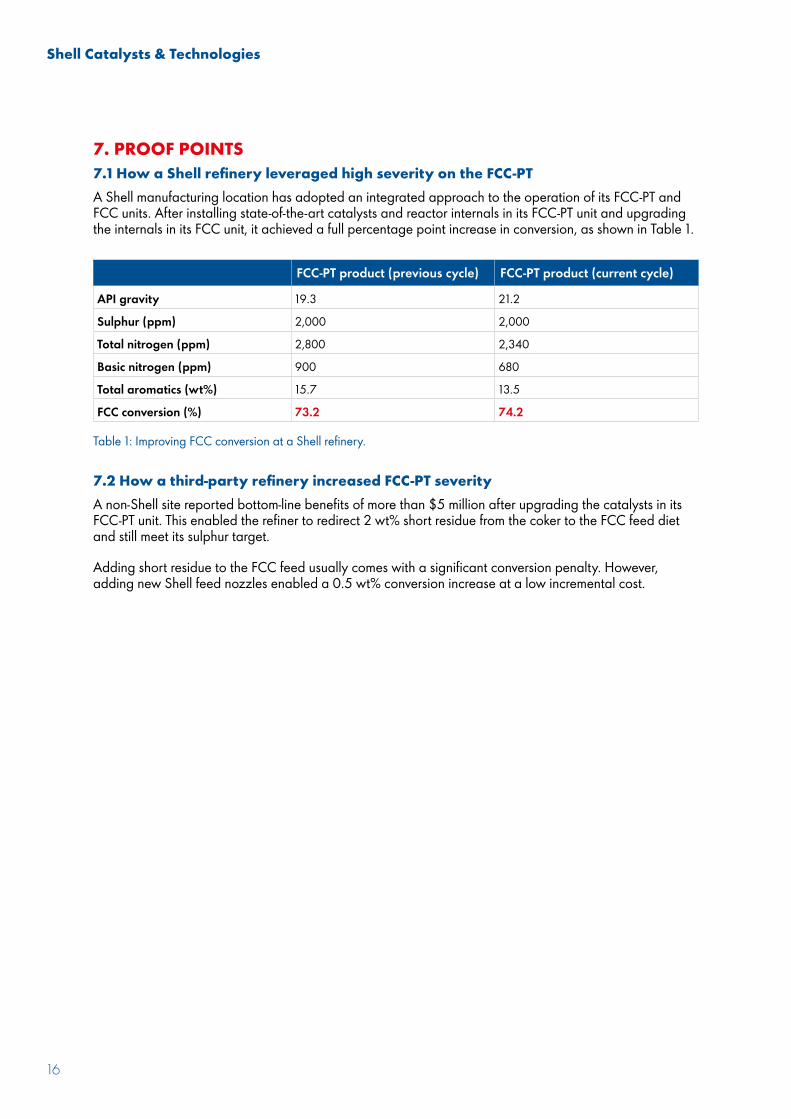
7. PROOF POINTS7.1 How a Shell refinery leveraged high severity on the FCC-PTA Shell manufacturing location has adopted an integrated approach to the operation of its FCC-PT and FCC units. After installing state-of-the-art catalysts and reactor internals in its FCC-PT unit and upgrading the internals in its FCC unit, it achieved a full percentage point increase in conversion, as shown in Table 1.
7.2 How a third-party refinery increased FCC-PT severityA non-Shell site reported bottom-line benefits of more than $5 million after upgrading the catalysts in its FCC-PT unit. This enabled the refiner to redirect 2 wt% short residue from the coker to the FCC feed diet and still meet its sulphur target.
Adding short residue to the FCC feed usually comes with a significant conversion penalty. However, adding new Shell feed nozzles enabled a 0.5 wt% conversion increase at a low incremental cost.
FCC-PT product (previous cycle) FCC-PT product (current cycle)
API gravity 19.3 21.2
Sulphur (ppm) 2,000 2,000
Total nitrogen (ppm) 2,800 2,340
Basic nitrogen (ppm) 900 680
Total aromatics (wt%) 15.7 13.5
FCC conversion (%) 73.2 74.2
Table 1: Improving FCC conversion at a Shell refinery.
Shell Catalysts & Technologies
17
8. FUTURE OPPORTUNITIESAcross the industry, there is a growing interest in crude-oil-to-chemicals projects, whereby the complex is designed to maximise non-fuel revenue streams such as petrochemicals, and a need to process difficult feeds. FCC-PT–FCC unit integration can help to achieve these objectives.
8.1 Crude oil to chemicalsTo help maximise petrochemical yields, refiners could: increase severity in the FCC-PT unit by changing the catalyst or adding reactor volume by installing latest-generation reactor internals;
upgrade to the latest-generation FCC feed nozzles to improve yields and move to close-coupled cyclones to reduce dry gas and gain capacity in the workup section;
optimise the FCC catalyst (more activity, less coke selectivity) through a catalyst selection study, then utilise SHARC modelling to realise those gains; and
upgrade the distillation hardware by using Shell HiFi trays to gain capacity in the recovery section.
8.2 Process difficult feedsTo help process more difficult feeds, refiners could: add more demetallisation capability and increase the severity in the FCC-PT unit for better metals reduction and saturation to improve FCC yields;
upgrade FCC feed nozzles for better yields, add PentaFlow stripper baffles for lower hydrogen and coke to gain regenerator capacity, and upgrade cyclones to reduce post-riser cracking and reactor vessel coking; and
use SHARC modelling to optimise the FCC catalyst.
Shell Catalysts & Technologies
18
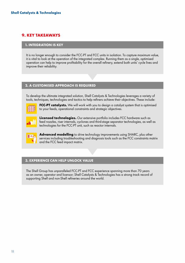
9. KEY TAKEAWAYS
1. INTEGRATION IS KEY
2. A CUSTOMISED APPROACH IS REQUIRED
3. EXPERIENCE CAN HELP UNLOCK VALUE
It is no longer enough to consider the FCC-PT and FCC units in isolation. To capture maximum value, it is vital to look at the operation of the integrated complex. Running them as a single, optimised operation can help to improve profitability for the overall refinery, extend both units’ cycle lives and improve their reliability.
To develop the ultimate integrated solution, Shell Catalysts & Technologies leverages a variety of tools, techniques, technologies and tactics to help refiners achieve their objectives. These include:
FCC-PT catalysts. We will work with you to design a catalyst system that is optimised to your feeds, operational constraints and strategic objectives.
Licensed technologies. Our extensive portfolio includes FCC hardware such as feed nozzles, riser internals, cyclones and third-stage separator technologies, as well as technologies for the FCC-PT unit, such as reactor internals.
Advanced modelling to drive technology improvements using SHARC, plus other services including troubleshooting and diagnosis tools such as the FCC constraints matrix and the FCC feed impact matrix.
The Shell Group has unparalleled FCC-PT and FCC experience spanning more than 70 years as an owner, operator and licensor; Shell Catalysts & Technologies has a strong track record of supporting Shell and non-Shell refineries around the world.
Shell Catalysts & Technologies
19
ABOUT THE AUTHORS
Kevin Carlson is the Shell Catalysts & Technologies Global Application Manager for naphtha and vacuum gas oils. He has been involved in many segments of the downstream refining industry for more than 30 years with emphasis on hydroprocessing process optimisation.
Todd Foshee is the Shell Catalysts & Technologies FCC Licensing Technology Manager. He is part of a team responsible for process design on FCC projects for Shell and third-party customers. Todd has BSc and MSc degrees in chemical engineering and 25 years of experience in the hydrocarbon processing industry that includes process design, site support and operations.
ABOUT SHELL CATALYSTS & TECHNOLOGIESShell Catalysts & Technologies supports Shell and non-Shell businesses by working with them to co-create integrated, customised solutions comprising licensed technologies, refining and petrochemical catalysts, and technical services.
It was formed by combining Shell Global Solutions, a technology licensor with a track record of delivering pioneering process schemes and innovative configurations; Criterion Catalysts & Technologies, the world’s largest hydroprocessing catalyst supplier; and CRI Catalyst Company, a pioneer in the petrochemical catalyst sector.
It operates across the energy value chain, from upstream, gas processing and LNG through to downstream refining and petrochemicals.
The fact that Shell Catalysts & Technologies supports Shell’s global downstream network means that it has already addressed many of the challenges that its third-party customers face – the catalysts and technologies that it licenses have been developed in response to the same challenges.
For further information, please visit our website at www.shell.com/ct.

Shell Catalysts & Technologies is a network of independent technology companies in the Shell Group. In this material, the expressions “the Shell Group” and “Shell Catalysts & Technologies” are sometimes used for convenience where reference is made to these companies in general, or where no useful purpose is served by identifying a particular company.
The information contained in this material is intended to be general in nature and must not be relied on as specific advice in connection with any decisions you may make. Shell Catalysts & Technologies is not liable for any action you may take as a result of you relying on such material or for any loss or damage suffered by you as a result of you taking this action. Furthermore, these materials do not in any way constitute an offer to provide specific services. Some services may not be available in certain countries or political subdivisions thereof.
Copyright © 2019 Shell Global Solutions International BV. All rights reserved. No part of this publication may be reproduced or transmitted in any form or by any means, electronic or mechanical including by photocopy, recording or information storage and retrieval system, without permission in writing from Shell Global Solutions International BV.