sheraton hotel, jogjakarta 26 november...
TRANSCRIPT

Sheraton Hotel, Sheraton Hotel, Sheraton Hotel, Sheraton Hotel,
26 November26 November26 November26 November
Sheraton Hotel, Sheraton Hotel, Sheraton Hotel, Sheraton Hotel,
26 November26 November26 November26 November
Muhammad Ary [email protected]
Sheraton Hotel, Sheraton Hotel, Sheraton Hotel, Sheraton Hotel, Jogjakarta Jogjakarta Jogjakarta Jogjakarta
26 November26 November26 November26 November 2013201320132013
Sheraton Hotel, Sheraton Hotel, Sheraton Hotel, Sheraton Hotel, Jogjakarta Jogjakarta Jogjakarta Jogjakarta
26 November26 November26 November26 November 2013201320132013
Muhammad Ary [email protected]

AgendaLegacy M2M Protocols for Sensor Networks,Building Automation and Home Automation
• The BACnet™ Protocol• The BACnet™ Protocol
• The LonWorks® Control Networking
Platform
• ModBus
• KNX
• ZigBee
• Z-Wave
Legacy M2M Protocols for Utility Metering
• M-Bus and Wireless M-Bus
• The ANSI C12 Suite
• DLMS/COSEM
Thanks to Arief Hamdani Gunawan for great slide of IoT
AgendaLegacy M2M Protocols for Sensor Networks,Building Automation and Home Automation
The Next Generation : IP-Based Protocols• 6LoWPAN and RPL
Legacy M2M Protocols for Utility Metering
• 6LoWPAN and RPL• ZigBee Smart Energy 2.0• The ETSI M2M Architecture
Key Applications of the Internet of Things
• The Smart Grid• The Smart Grid
• Electric Vehicle Charging
Thanks to Arief Hamdani Gunawan for great slide of IoT

6LoWPAN and RPL6LoWPAN and RPL6LoWPAN and RPL6LoWPAN and RPL
Background
• Traditionally, battery-powered networks or lowbitrate networks, such as most bitrate networks, such as most or 802.15.4 were considered incapable of runningIP.
• In the home and industrial automation networksworld, the situation compares to the situation ofcorporate LANs in the 1980s:
“should I run Token-Ring, ATM or “should I run Token-Ring, ATM or
translates to
“should I run ZigBee, LON or KNX?”
Background
powered networks or low-networks, such as most fieldbus networksnetworks, such as most fieldbus networks
802.15.4 were considered incapable of running
In the home and industrial automation networksworld, the situation compares to the situation ofcorporate LANs in the 1980s:
Ring, ATM or IPX/SPX?”Ring, ATM or IPX/SPX?”
translates to
“should I run ZigBee, LON or KNX?”

IP
• IP, with its concept of layer 3 routing andinternetwork technology, has made thoseinternetwork technology, has made thosedebates about incompatible networksobsolete: the vast majority of LANs and WANstoday run IP, and many people can hardlyremember which layer 2 technology their IPnetworks are running on.networks are running on.
• Almost any layer 2 technology can be usedand will simply extend the IP internetwork.
IP
IP, with its concept of layer 3 routing andinternetwork technology, has made thoseinternetwork technology, has made thosedebates about incompatible networksobsolete: the vast majority of LANs and WANstoday run IP, and many people can hardlyremember which layer 2 technology their IPnetworks are running on.networks are running on.
Almost any layer 2 technology can be usedand will simply extend the IP internetwork.
6LoWPAN and RPL
The same transition to IP is now happening in
the home and industrial automation worlds.the home and industrial automation worlds.
6LoWPAN and RPL have made this possible.
6LoWPAN and RPL
The same transition to IP is now happening in
the home and industrial automation worlds.the home and industrial automation worlds.
6LoWPAN and RPL have made this possible.

6LoWPANs
• The Internet Engineering Task Force (IETF)6LoWPAN Working Group was formed in 6LoWPAN Working Group was formed in design an adaptation layer for over 802.15.4 low-power and (LowPAN or LLN).
• The work included a detailed review ofrequirements, which were released in 2007 (RFC4919): “IPv6 over Low-Power Wireless PersonalArea Networks (6LoWPANsArea Networks (6LoWPANsAssumptions, Problem Statement, and Goals”http://tools.ietf.org/html/rfc4919
6LoWPANs
The Internet Engineering Task Force (IETF)Working Group was formed in 2004 toWorking Group was formed in 2004 to
design an adaptation layer for IPv6 when runningpower and lossy networks
The work included a detailed review ofrequirements, which were released in 2007 (RFC
Power Wireless Personal6LoWPANs): Overview,6LoWPANs): Overview,
Assumptions, Problem Statement, and Goals”http://tools.ietf.org/html/rfc4919

IEEE 802.15.4
• Low-power wireless personal area networks(LoWPANs) comprise devices that conform (LoWPANs) comprise devices that conform the IEEE 802.15.4-2003 standard by the IEEE.
• IEEE 802.15.4 devices are characterized byshort range, low bit rate, low power, and lowcost.
• Many of the devices employing IEEE 802.15.4• Many of the devices employing IEEE 802.15.4radios will be limited in their computationalpower, memory, and/or energy availability.
IEEE 802.15.4
power wireless personal area networkscomprise devices that conform tocomprise devices that conform to
2003 standard by the IEEE.
IEEE 802.15.4 devices are characterized byshort range, low bit rate, low power, and low
Many of the devices employing IEEE 802.15.4Many of the devices employing IEEE 802.15.4radios will be limited in their computationalpower, memory, and/or energy availability.

In Practice…
• In practice, however, the 6LoWPAN is notrestricted to radio links, and restricted to radio links, and be extended to run over other mediainstance it has been extended to run over lowpower CPL (www.watteco.com
• IPv6 is also being adapted to other physicallayers, independently of 6LoWPAN, for example,for HomePlug CPL.for HomePlug CPL.
• Many fieldbus vendors are now considering anIPv6 adaptation layer for their products
In Practice…
In practice, however, the 6LoWPAN is notrestricted to radio links, and the technology canrestricted to radio links, and the technology canbe extended to run over other media, forinstance it has been extended to run over low-
www.watteco.com) or G3 OFDM CPL.
IPv6 is also being adapted to other physicallayers, independently of 6LoWPAN, for example,
vendors are now considering anadaptation layer for their products
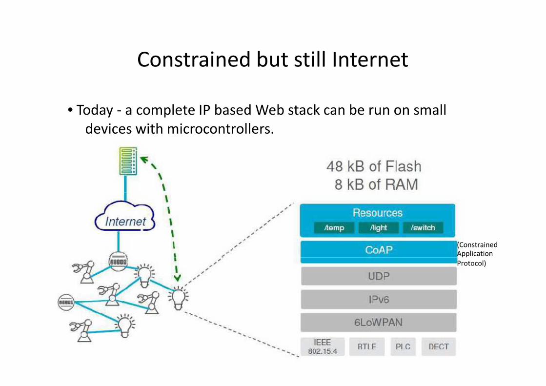
Constrained but still Internet
• Today - a complete IP based Web stack can be run on small
devices with microcontrollers.devices with microcontrollers.
Constrained but still Internet
a complete IP based Web stack can be run on small
devices with microcontrollers.devices with microcontrollers.
(Constrained
ApplicationApplication
Protocol)

IETF 6LoWPAN
• The 6LoWPAN WG group has defined encapsulationand header compression mechanisms that allow and header compression mechanisms that allow packets to be sent and received over IEEE 802.15.4based networks. IEEE 802.15.4 maximum transfer unit(MTU) is limited to 127 bytes.
• Taking into account frame overhead and optionalsecurity headers, very little is left for upper layers, thatis, TCP/IP and application payload, unless protocoloverhead is optimized.
• In essence, the 6LowPAN work allows IP to be used all• In essence, the 6LowPAN work allows IP to be used allthe way to constrained devices, a desirable feature toallow for an end-to-end IP-based communication.
IETF 6LoWPAN
group has defined encapsulationmechanisms that allow IPv6mechanisms that allow IPv6
packets to be sent and received over IEEE 802.15.4-based networks. IEEE 802.15.4 maximum transfer unit
) is limited to 127 bytes.
Taking into account frame overhead and optionalsecurity headers, very little is left for upper layers, thatis, TCP/IP and application payload, unless protocol
In essence, the 6LowPAN work allows IP to be used allIn essence, the 6LowPAN work allows IP to be used allthe way to constrained devices, a desirable feature to
based communication.
6LoWPAN: Why IPv6?
• Long-lived technology (20 years+)
• Ability to connect heterogeneous networks
• Existing worldwide free
• Global scalability
• 2^128 Bit (16 Byte) Addressing = Enough for
Internet of ThingsInternet of Things
• Great number of tools (diagnostic,
management etc.)
6LoWPAN: Why IPv6?
lived technology (20 years+)
Ability to connect heterogeneous networks
Existing worldwide free-to-use infrastructure
2^128 Bit (16 Byte) Addressing = Enough for
Great number of tools (diagnostic,
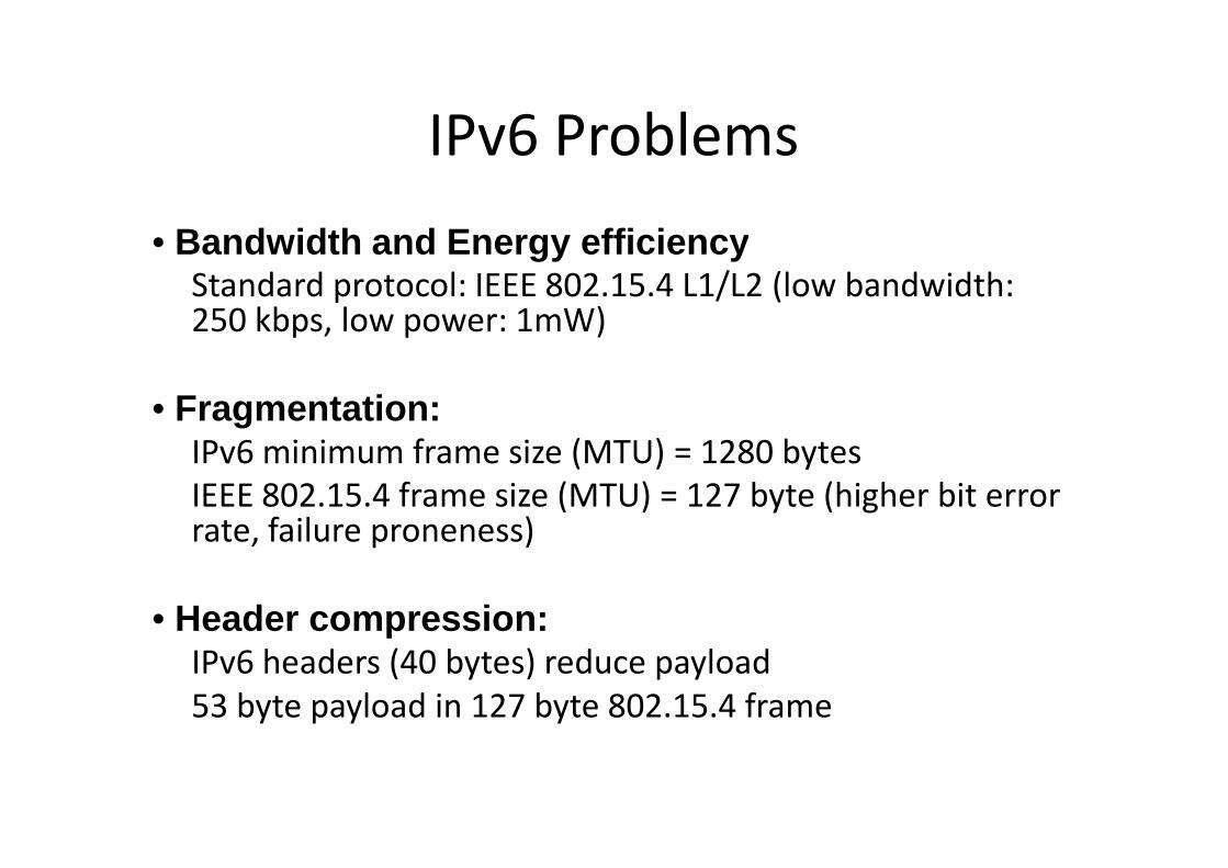
IPv6 Problems
• Bandwidth and Energy efficiencyStandard protocol: IEEE 802.15.4 L1/L2 (low bandwidth:Standard protocol: IEEE 802.15.4 L1/L2 (low bandwidth:250 kbps, low power: 1mW)
• Fragmentation:IPv6 minimum frame size (MTU) = 1280 bytes
IEEE 802.15.4 frame size (MTU) = 127 byte (higher bit errorrate, failure proneness)
• Header compression:IPv6 headers (40 bytes) reduce payload
53 byte payload in 127 byte 802.15.4 frame
IPv6 Problems
Bandwidth and Energy efficiencyStandard protocol: IEEE 802.15.4 L1/L2 (low bandwidth:Standard protocol: IEEE 802.15.4 L1/L2 (low bandwidth:
IPv6 minimum frame size (MTU) = 1280 bytes
IEEE 802.15.4 frame size (MTU) = 127 byte (higher bit error
IPv6 headers (40 bytes) reduce payload
53 byte payload in 127 byte 802.15.4 frame

IPv6 Problems
• Mobility:Node Mobility and Network MobilityNode Mobility and Network Mobility
• Review of Transport Layer Protocols:TCP inefficient for wireless embedded devices (wireless packet lost)
• Handle offline devices:• IP assumes devices are always on, but embedded devices may not
(power and duty cycles)
• Multicast support:IEEE 802.15.4 & other radios do not support Multicast (expensive)
IPv6 Problems
Node Mobility and Network MobilityNode Mobility and Network Mobility
Review of Transport Layer Protocols:TCP inefficient for wireless embedded devices (wireless packet lost)
IP assumes devices are always on, but embedded devices may not
IEEE 802.15.4 & other radios do not support Multicast (expensive)
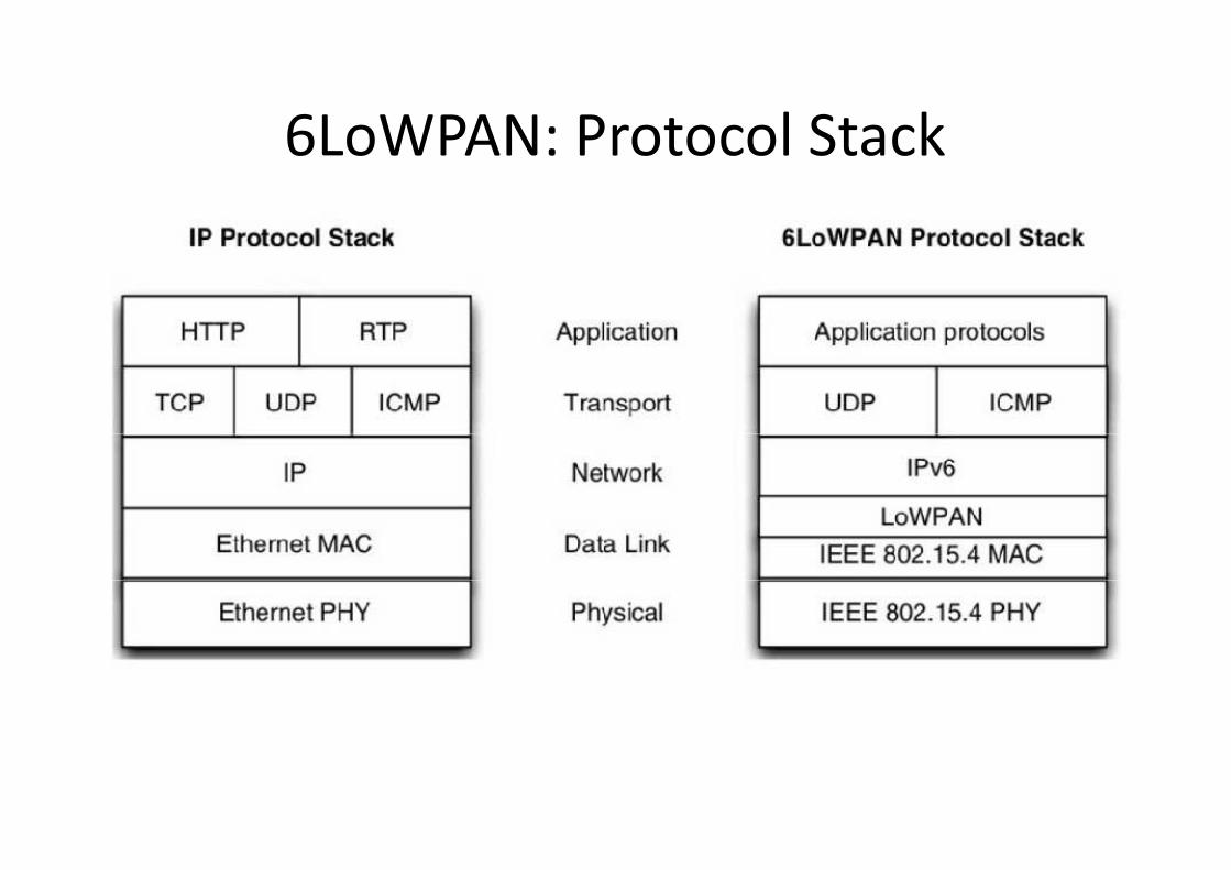
6LoWPAN: Protocol Stack6LoWPAN: Protocol Stack

6LoWPAN: Architecture6LoWPAN: Architecture
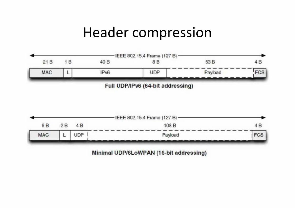
Header compressionHeader compression
ZigBee Smart Energy 2.0ZigBee Smart Energy 2.0ZigBee Smart Energy 2.0ZigBee Smart Energy 2.0


ZigBee SEP 2.0 Overview
• The ZigBee Smart Energy Profile 2.0 protocol is
the result of a joint work of the the result of a joint work of the
and of the HomePlug powerline
is behind the HomePlug/AV (draft IEEE P1901)
CPL standard and working on the “Green
CPL standard.
ZigBee SEP 2.0 Overview
Smart Energy Profile 2.0 protocol is
joint work of the ZigBee alliancejoint work of the ZigBee alliance
powerline Alliance, who
/AV (draft IEEE P1901)
CPL standard and working on the “Green Phy”

Redesign an equivalent of ZigBee SE 1.0
• The idea was to redesign an equivalent of SE 1.0, but in a physical-layerSE 1.0, but in a physical-layerbased on an IP networking layer RESTful design.
• The clusters of ZigBee SE 1.0 are redesigned as“function sets” in SEP 2.0.
• In addition, the working group took into accounta comprehensive requirements list coming fromutility companies as well as the Society ofa comprehensive requirements list coming fromutility companies as well as the Society ofAutomotive Engineers (SAE) for aspects related toelectric vehicles.
Redesign an equivalent of ZigBee SE 1.0
The idea was to redesign an equivalent of ZigBeelayer-independent way,layer-independent way,
based on an IP networking layer and using a
The clusters of ZigBee SE 1.0 are redesigned as
In addition, the working group took into accounta comprehensive requirements list coming fromutility companies as well as the Society ofa comprehensive requirements list coming fromutility companies as well as the Society ofAutomotive Engineers (SAE) for aspects related to

ZigBee Smart Energy 1.1
ZigBee Smart Energy 1.1 is an incremental release of theZigBee Smart Energy standard. ZigBee Smart Energy 1.1 addstwo categories of features,ZigBee Smart Energy standard. ZigBee Smart Energy 1.1 addstwo categories of features,
• The first introduces new optional functionality, including:- Block tariffs (inclining/declining block rates)
– Meter swap outs
- Tunneling of manufacturer specific protocols
- Prepayment
- Over-the-air upgrades
- Backwards compatibility- Backwards compatibility
• The second category includes enhancements to the testspecification to further device interoperability.
ZigBee Smart Energy 1.1
ZigBee Smart Energy 1.1 is an incremental release of theZigBee Smart Energy standard. ZigBee Smart Energy 1.1 addsZigBee Smart Energy standard. ZigBee Smart Energy 1.1 adds
The first introduces new optional functionality, including:Block tariffs (inclining/declining block rates)
Tunneling of manufacturer specific protocols
The second category includes enhancements to the testspecification to further device interoperability.

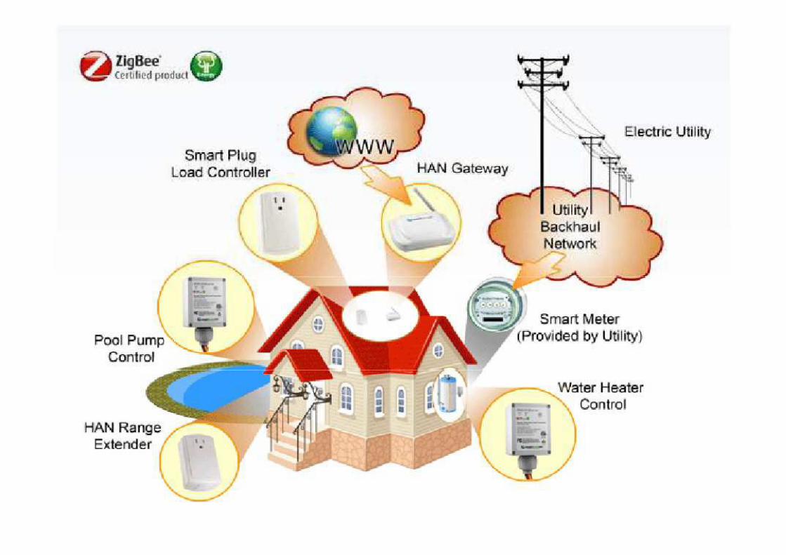
ZigBee Smart Energy 2.0
The SEP 2 standard offers IP- based Home Area Network (HAN)management functionality and was ratified in April 2013.
It addresses the following needs of the market:It addresses the following needs of the market:
• Deployments in multi-dwelling units such as apartment buildings
• Supports multiple Energy Service Interfaces into a single premises
• Control of plug in hybrid electric vehicle (PHEV) charging
• Supports any transport based on IETF IP compliant standards,including but not limited to ZigBee IP, other RFLine Carrier (PLC)-based transports
• Supports internationally recognized standards to ensure longinteroperability with multiple technologies
• Supports internationally recognized standards to ensure longinteroperability with multiple technologies
ZigBee Smart Energy 2.0
based Home Area Network (HAN) energymanagement functionality and was ratified in April 2013.
It addresses the following needs of the market:It addresses the following needs of the market:
dwelling units such as apartment buildings
Supports multiple Energy Service Interfaces into a single premises
Control of plug in hybrid electric vehicle (PHEV) charging
Supports any transport based on IETF IP compliant standards,including but not limited to ZigBee IP, other RF-based and Power
based transports
Supports internationally recognized standards to ensure long-terminteroperability with multiple technologies
Supports internationally recognized standards to ensure long-terminteroperability with multiple technologies

Adoption of networking standards
• Accomplishing these goals has led to the adoption ofnetworking standards that ensure interoperabilitynetworking standards that ensure interoperabilitybetween ZigBee and other network technologies.
• The ZigBee Alliance developed an internet protocol (IP)networking specification called ZigBee IP which isbased on existing IETF protocols such as 6LoWPAN,mDNS, ROLL routing etc.
• The application function sets implemented for SEP 2• The application function sets implemented for SEP 2have been mapped to the IEC Common InformationModel. Additional data beyond the IEC CommonInformation Model will be proposed back into IEC
Adoption of networking standards
Accomplishing these goals has led to the adoption ofnetworking standards that ensure interoperabilitynetworking standards that ensure interoperabilitybetween ZigBee and other network technologies.
The ZigBee Alliance developed an internet protocol (IP)networking specification called ZigBee IP which isbased on existing IETF protocols such as 6LoWPAN,
The application function sets implemented for SEP 2The application function sets implemented for SEP 2have been mapped to the IEC Common InformationModel. Additional data beyond the IEC CommonInformation Model will be proposed back into IEC

Assumption
• SEP 2.0 assumes an all IPv6 network.
• The protocol is designed according to the REST
paradigm, and the data model is intended to
map directly to IEC 61968 (the “common
information model”).
• Resources are modeled using XML, and• Resources are modeled using XML, and
resource representations are compressed
using EXI
Assumption
SEP 2.0 assumes an all IPv6 network.
The protocol is designed according to the REST
paradigm, and the data model is intended to
map directly to IEC 61968 (the “common
Resources are modeled using XML, andResources are modeled using XML, and
resource representations are compressed

AMI = Automatic Metering Infrastructure

The ETSI M2M ArchitectureThe ETSI M2M Architecture
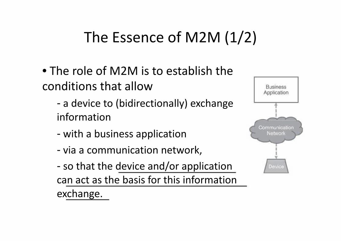
The Essence of M2M (1/2)
• The role of M2M is to establish the
conditions that allowconditions that allow
- a device to (bidirectionally) exchange
information
- with a business application
- via a communication network,
- so that the device and/or application- so that the device and/or application
can act as the basis for this information
exchange.
The Essence of M2M (1/2)
The role of M2M is to establish the
a device to (bidirectionally) exchange
with a business application
via a communication network,
so that the device and/or applicationso that the device and/or application
can act as the basis for this information

The Essence of M2M (2/2)
• The basic way to describe M2M isshown in the “essence” of M2M.shown in the “essence” of M2M.
- The role of M2M is to establish theconditions that allow a device to(bidirectionally) exchange informationwith a business application via acommunication network, so that thedevice and/or application can act as thebasis for this information exchange.
- In this definition, the communication- In this definition, the communicationnetwork has a key role:
a collocated application and device can hardlybe considered as having an M2M relationship.
The Essence of M2M (2/2)
The basic way to describe M2M isshown in the “essence” of M2M.shown in the “essence” of M2M.
The role of M2M is to establish theconditions that allow a device to(bidirectionally) exchange informationwith a business application via acommunication network, so that thedevice and/or application can act as thebasis for this information exchange.
In this definition, the communicationIn this definition, the communication
a collocated application and device can hardlybe considered as having an M2M relationship.
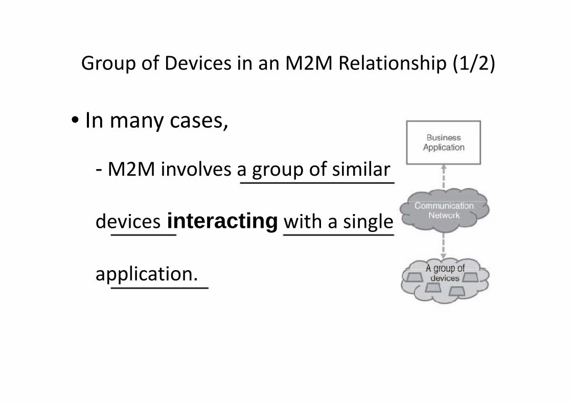
Group of Devices in an M2M Relationship (1/2)
• In many cases,
- M2M involves a group of similar
devices interacting with a single
application.application.
Group of Devices in an M2M Relationship (1/2)
M2M involves a group of similar
with a single

Group of Devices in an M2M Relationship (2/2)
• In many cases, M2M involves a group
of similar devices interacting with aof similar devices interacting with a
single application.
• Fleet management is an example of
such an application, where devices are
for example, trucks, and the
communication network is a mobile
network.network.
Group of Devices in an M2M Relationship (2/2)
In many cases, M2M involves a group
of similar devices interacting with aof similar devices interacting with a
Fleet management is an example of
such an application, where devices are
for example, trucks, and the
communication network is a mobile
The Mediated M2M Relationship (1/2)
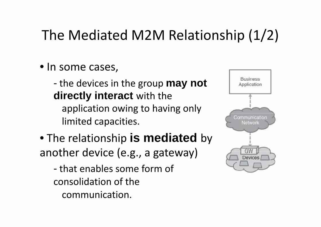
• In some cases,
- the devices in the group
directly interact with the
application owing to having only
limited capacities.
• The relationship is mediated another device (e.g., a gateway)another device (e.g., a gateway)
- that enables some form of
consolidation of the
communication.
The Mediated M2M Relationship (1/2)
the devices in the group may notwith the
application owing to having only
is mediated by
another device (e.g., a gateway)another device (e.g., a gateway)
that enables some form of

The Mediated M2M Relationship (2/2)
• In some cases, the devices in thegroup may not directly interact withgroup may not directly interact withthe application owing to having onlylimited capacities.
• In this scenario, the relationship ismediated by another device (e.g., agateway) that enables some form ofconsolidation of the communication.
• “Smart metering” is an example ofsuch an application where the devices
• “Smart metering” is an example ofsuch an application where the devicesare smart meters and thecommunication network can be amobile network or the public Internet
The Mediated M2M Relationship (2/2)
In some cases, the devices in thegroup may not directly interact withgroup may not directly interact withthe application owing to having only
In this scenario, the relationship ismediated by another device (e.g., agateway) that enables some form ofconsolidation of the communication.
“Smart metering” is an example ofsuch an application where the devices“Smart metering” is an example ofsuch an application where the devices
communication network can be amobile network or the public Internet
M2M area network
• The term “M2M area network” has been introduced
by the European Telecommunication Standardsby the European Telecommunication Standards
Institute (ETSI).
• An M2M area network provides
- physical and
- MAC layer connectivity
between different M2M devices connectedbetween different M2M devices connected
to the same M2M area network,
thus allowing M2M devices to gain access
to a public network via a router or a gateway.
M2M area network
The term “M2M area network” has been introduced
by the European Telecommunication Standardsby the European Telecommunication Standards
An M2M area network provides
between different M2M devices connectedbetween different M2M devices connected
to the same M2M area network,
thus allowing M2M devices to gain access
to a public network via a router or a gateway.
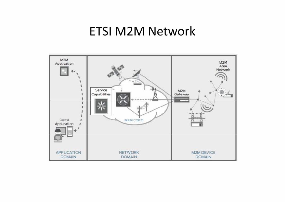
ETSI M2M NetworkETSI M2M Network
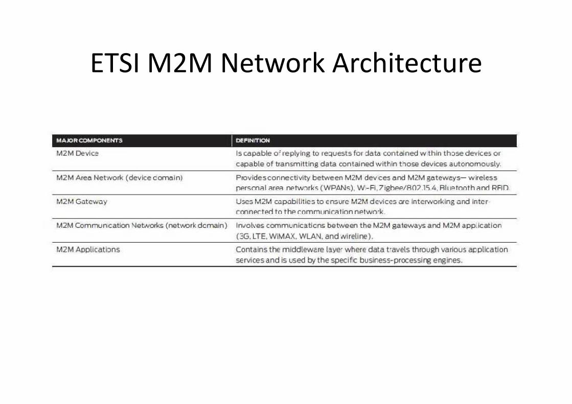
ETSI M2M Network ArchitectureETSI M2M Network Architecture
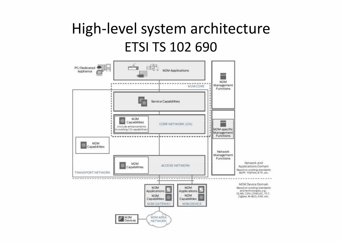
High-level system architectureETSI TS 102 690
level system architectureETSI TS 102 690

M2M High Level System OverviewM2M High Level System Overview
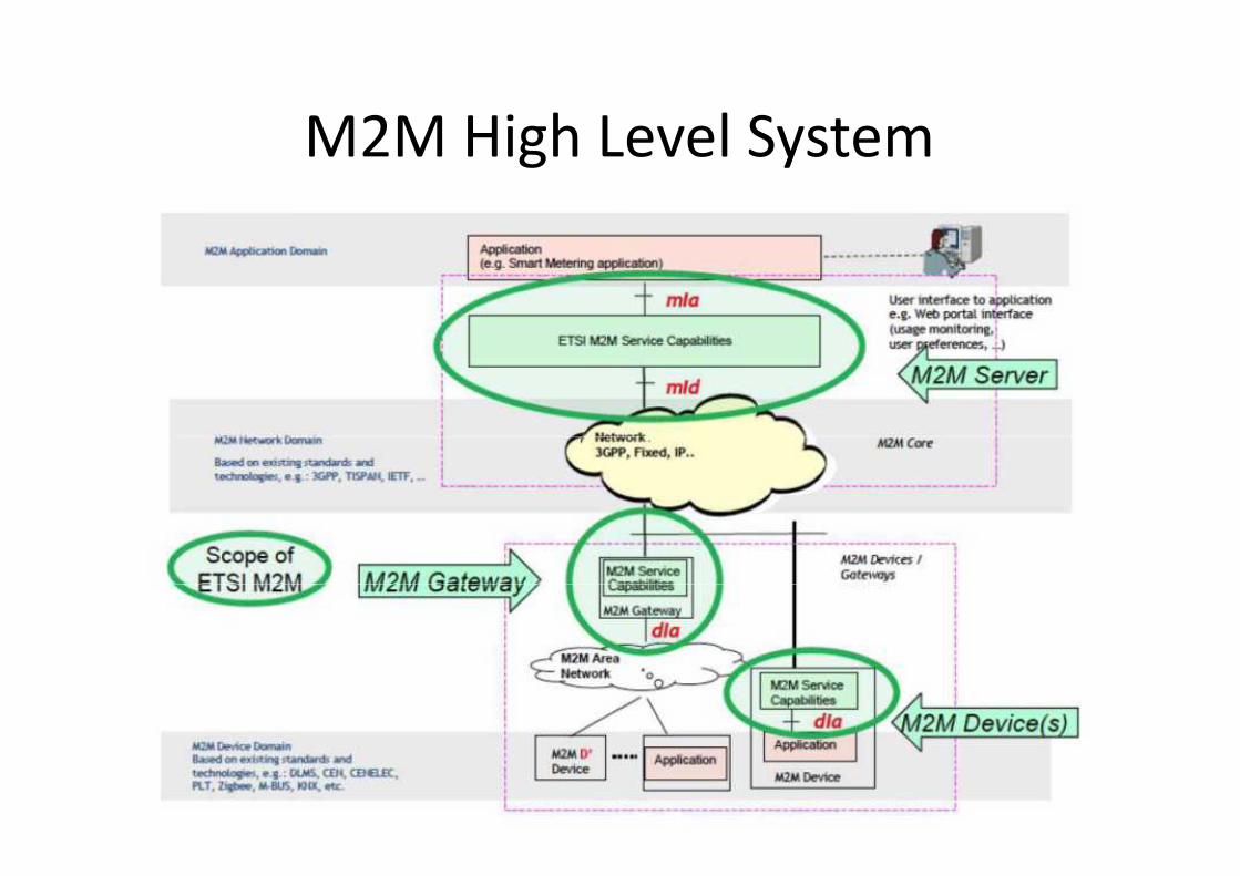
M2M High Level SystemM2M High Level System
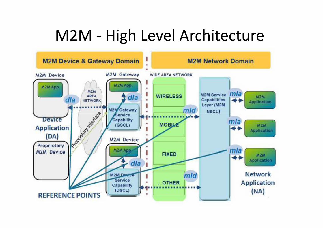
M2M - High Level ArchitectureHigh Level Architecture
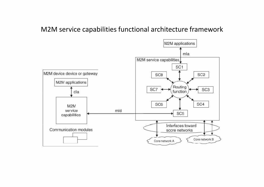
M2M service capabilities functional architecture frameworkM2M service capabilities functional architecture framework
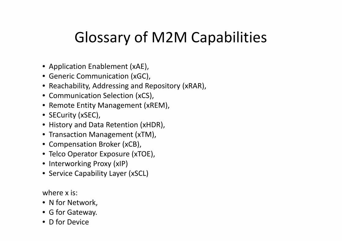
Glossary of M2M Capabilities
• Application Enablement (xAE),
• Generic Communication (xGC),• Generic Communication (xGC),
• Reachability, Addressing and Repository (xRAR),
• Communication Selection (xCS),
• Remote Entity Management (xREM),
• SECurity (xSEC),
• History and Data Retention (xHDR),
• Transaction Management (xTM),
• Compensation Broker (xCB),
• Telco Operator Exposure (xTOE),
• Interworking Proxy (xIP)• Interworking Proxy (xIP)
• Service Capability Layer (xSCL)
where x is:
• N for Network,
• G for Gateway.
• D for Device
Glossary of M2M Capabilities
Reachability, Addressing and Repository (xRAR),

Main Concept of REST
• The main concept of REST is that a distributed application iscomposed of resources, which are stateful pieces of informationresiding on one or more servers.residing on one or more servers.
• Regardless of their content, in REST it is possible to manipulateresources through a uniform interface that is composed of fourbasic interactions: CREATE, UPDATE, DELETE, and READ.
• Each of these operations is composed of request and responsemessages, and, with the exception of CREATE, they are idempotent,meaning that the end result of each operation is unchangedregardless of how many times the operation itself is repeated.
• In other words, these operations do not have side effects, meaning• In other words, these operations do not have side effects, meaningthat it is possible to distribute resources and to use proxy functions.The lack of side effects allows more efficient use of caching andgreater scalability.
Main Concept of REST
The main concept of REST is that a distributed application iscomposed of resources, which are stateful pieces of information
Regardless of their content, in REST it is possible to manipulateresources through a uniform interface that is composed of fourbasic interactions: CREATE, UPDATE, DELETE, and READ.
Each of these operations is composed of request and responsemessages, and, with the exception of CREATE, they are idempotent,meaning that the end result of each operation is unchangedregardless of how many times the operation itself is repeated.
In other words, these operations do not have side effects, meaningIn other words, these operations do not have side effects, meaningthat it is possible to distribute resources and to use proxy functions.The lack of side effects allows more efficient use of caching and

REST Basics
• REST is an architectural style that relies heavily
on HTTP, and conceptualizes the idea of webon HTTP, and conceptualizes the idea of web
accessible resources.
• A resource, in REST terms, could be any entity
that can be addressed using a HTTP URI
REST Basics
REST is an architectural style that relies heavily
on HTTP, and conceptualizes the idea of web-on HTTP, and conceptualizes the idea of web-
A resource, in REST terms, could be any entity
that can be addressed using a HTTP URI

Addressing a REST resourceAddressing a REST resource

Proxy caching the temperature valueProxy caching the temperature value
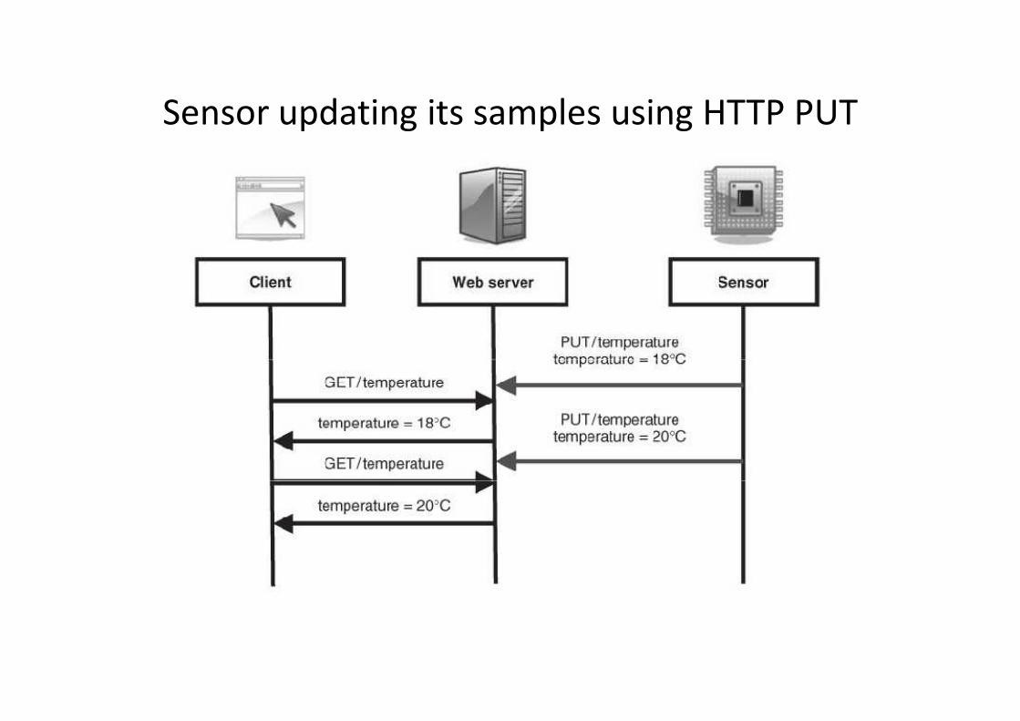
Sensor updating its samples using HTTP PUTSensor updating its samples using HTTP PUT

ETSI TC M2M Resource
Communication and Procedures
• In ETSI TC M2M, it is assumed that all threenormative reference points defined in thenormative reference points defined in theM2M architecture, namely mIa, mId, and dIa,will use REST, although there may be someexceptions.
• For instance, on the mId reference point,device management is performed usingdevice management is performed usingexisting protocols such as BBF TR069 and OMADM that are RPC-based.
ETSI TC M2M Resource-Based M2M
Communication and Procedures
In ETSI TC M2M, it is assumed that all threenormative reference points defined in thenormative reference points defined in theM2M architecture, namely mIa, mId, and dIa,will use REST, although there may be some
For instance, on the mId reference point,device management is performed usingdevice management is performed usingexisting protocols such as BBF TR069 and OMA
based.

Primitives
• ETSI TC M2M did not assume that the HTTPprotocol would be the protocol to be used forprotocol would be the protocol to be used forimplementation, although HTTP is the naturalchoice until CoAP (more adapted for constraineddevices) becomes widely deployed.
• To avoid the use of specific HTTP primitives, thissection will mostly use the four primitives:
- Create: create a resource.
Retrieve: read the content of the resource.- Retrieve: read the content of the resource.
- Update: write the content of the resource.
- Delete: delete the resource.
Primitives
ETSI TC M2M did not assume that the HTTPprotocol would be the protocol to be used forprotocol would be the protocol to be used forimplementation, although HTTP is the naturalchoice until CoAP (more adapted for constraineddevices) becomes widely deployed.
To avoid the use of specific HTTP primitives, thissection will mostly use the four primitives:
Create: create a resource.
Retrieve: read the content of the resource.Retrieve: read the content of the resource.
Update: write the content of the resource.
Delete: delete the resource.

CRUD Methods
• Those methods are referred to as the CRUDmethods below.methods below.
• In addition to these basic methods, it is often alsouseful to define methods for subscribing to achange of a resource (S) and a notification abouta change of a resource (N) included in a moregeneral RESTful architecture.
• It is assumed in what follows that CRUD and SN• It is assumed in what follows that CRUD and SNare applicable to the resources used in the SCL(service capability layer).
CRUD Methods
Those methods are referred to as the CRUD
In addition to these basic methods, it is often alsouseful to define methods for subscribing to achange of a resource (S) and a notification abouta change of a resource (N) included in a moregeneral RESTful architecture.
It is assumed in what follows that CRUD and SNIt is assumed in what follows that CRUD and SNare applicable to the resources used in the SCL

AgendaLegacy M2M Protocols for Sensor Networks,Building Automation and Home Automation
• The BACnet™ Protocol• The BACnet™ Protocol
• The LonWorks® Control Networking
Platform
• ModBus
• KNX
• ZigBee
• Z-Wave
Legacy M2M Protocols for Utility Metering
• M-Bus and Wireless M-Bus
• The ANSI C12 Suite
• DLMS/COSEM
AgendaLegacy M2M Protocols for Sensor Networks,Building Automation and Home Automation
The Next Generation : IP-Based Protocols
• 6LoWPAN and RPL
Legacy M2M Protocols for Utility Metering
• 6LoWPAN and RPL
• ZigBee Smart Energy 2.0• The ETSI M2M Architecture
Key Applications of theInternet of ThingsInternet of Things• The Smart Grid• Electric Vehicle Charging

Internet of ThingsShort Course
Key Applications
Internet of ThingsShort Course
Key Applications
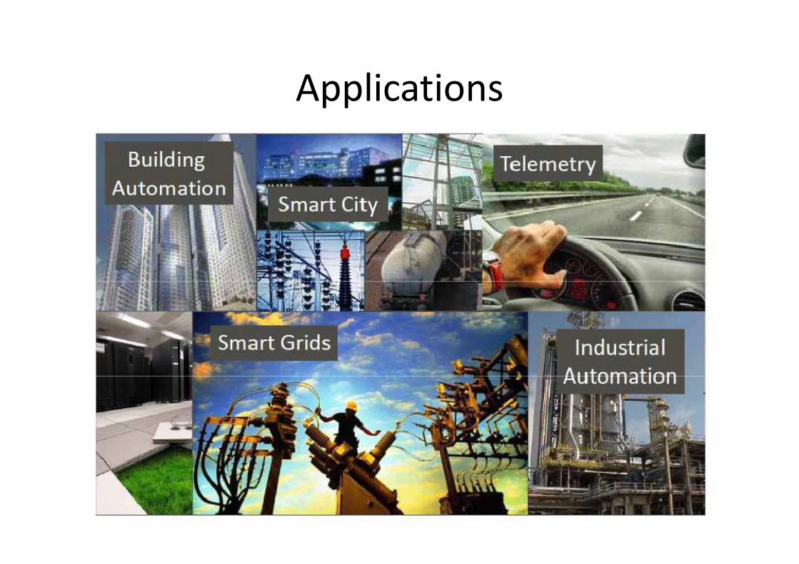
ApplicationsApplications

Key Applications
• The Smart Grid
• Electric Vehicle Charging
The Internet of Things: Key Applications and Protoc olsThe Internet of Things: Key Applications and Protoc olsBy Olivier Hersent, David Boswarthick, Omar Elloumi
John Wiley and Sons Ltd, January 2012
Key Applications
Electric Vehicle Charging
The Internet of Things: Key Applications and Protoc olsThe Internet of Things: Key Applications and Protoc olsBy Olivier Hersent, David Boswarthick, Omar Elloumi
John Wiley and Sons Ltd, January 2012

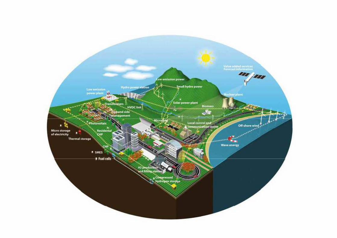
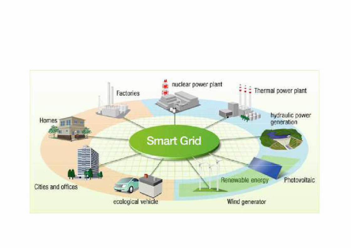
Smart Grid
Electrical grid that uses information and
communications technology to gather and actcommunications technology to gather and act
on information in an automated fashion to
improve the efficiency, reliability, economics,
and sustainability of the production and
distribution of electricity.
Smart Grid
Electrical grid that uses information and
communications technology to gather and actcommunications technology to gather and act
on information in an automated fashion to
improve the efficiency, reliability, economics,
and sustainability of the production and
distribution of electricity.

Historical Smart Grid Developments:
• EU initiated the smart grid project in 2003
• Electric Power Research Institute, USA, around
2003
• US DOE had a Grid 2030 project, around 2003
• NIST (National Institute of Standards and
Technology) is responsible as of 2007Technology) is responsible as of 2007
• Obama’s “National Broadband Plan” [March2010]
Historical Smart Grid Developments:
EU initiated the smart grid project in 2003
Electric Power Research Institute, USA, around
US DOE had a Grid 2030 project, around 2003
NIST (National Institute of Standards and
Technology) is responsible as of 2007Technology) is responsible as of 2007
Obama’s “National Broadband Plan” [March
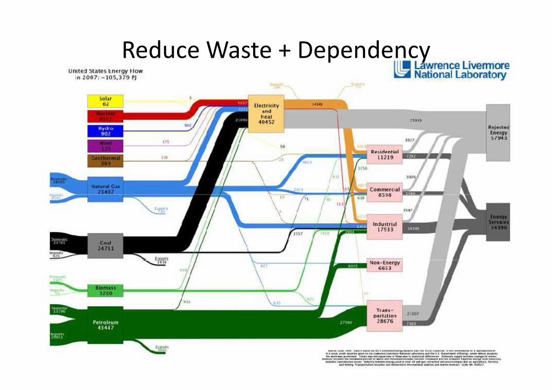
Reduce Waste + DependencyReduce Waste + Dependency

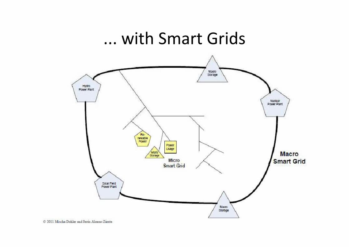
... with Smart Grids... with Smart Grids
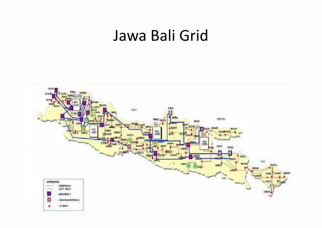
Jawa Bali GridJawa Bali Grid


Mission of ICT in Smart Grids
• enable energy efficiency
• keep bills at both ends low• keep bills at both ends low
• minimize greenhouse gas emissions
• automatically detect problems and route poweraround localized outages
• accommodate all types and volumes of energy,including alternativeincluding alternative
• make the energy system more resilient to alltypes of failures
Mission of ICT in Smart Grids
keep bills at both ends lowkeep bills at both ends low
minimize greenhouse gas emissions
automatically detect problems and route power
accommodate all types and volumes of energy,
make the energy system more resilient to all

TaxonomyTaxonomy
Smart Grid Comms Standards
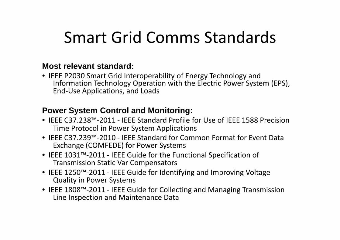
Most relevant standard:• IEEE P2030 Smart Grid Interoperability of Energy Technology and
Information Technology Operation with the Electric Power System (EPS),• IEEE P2030 Smart Grid Interoperability of Energy Technology and
Information Technology Operation with the Electric Power System (EPS),End-Use Applications, and Loads
Power System Control and Monitoring:• IEEE C37.238™-2011 - IEEE Standard Profile for Use of IEEE 1588 Precision
Time Protocol in Power System Applications
• IEEE C37.239™-2010 - IEEE Standard for Common Format for Event DataExchange (COMFEDE) for Power Systems
• IEEE 1031™-2011 - IEEE Guide for the Functional Specification ofTransmission Static Var CompensatorsTransmission Static Var Compensators
• IEEE 1250™-2011 - IEEE Guide for Identifying and Improving VoltageQuality in Power Systems
• IEEE 1808™-2011 - IEEE Guide for Collecting and Managing TransmissionLine Inspection and Maintenance Data
Smart Grid Comms Standards
IEEE P2030 Smart Grid Interoperability of Energy Technology andInformation Technology Operation with the Electric Power System (EPS),
IEEE P2030 Smart Grid Interoperability of Energy Technology andInformation Technology Operation with the Electric Power System (EPS),
Power System Control and Monitoring:IEEE Standard Profile for Use of IEEE 1588 Precision
Time Protocol in Power System Applications
IEEE Standard for Common Format for Event DataExchange (COMFEDE) for Power Systems
IEEE Guide for the Functional Specification ofTransmission Static Var CompensatorsTransmission Static Var Compensators
IEEE Guide for Identifying and Improving Voltage
IEEE Guide for Collecting and Managing TransmissionLine Inspection and Maintenance Data

IEEE P2030 Smart Grid InteroperabilityIEEE P2030 Smart Grid Interoperability
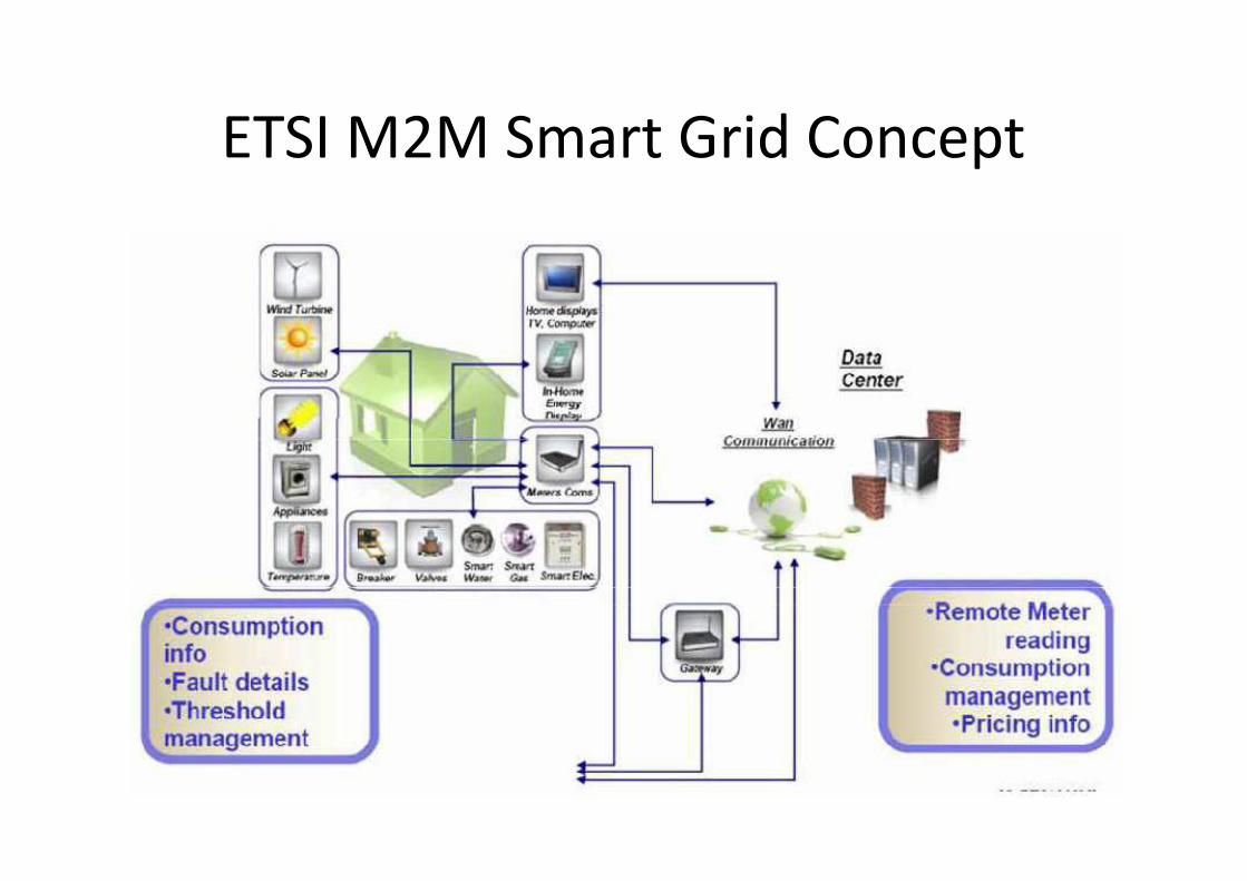
ETSI M2M Smart Grid ConceptETSI M2M Smart Grid Concept

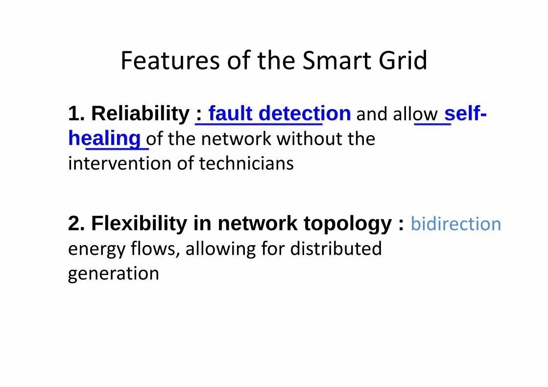
Features of the Smart Grid
1. Reliability : fault detectionhealing of the network without thehealing of the network without the
intervention of technicians
2. Flexibility in network topology : energy flows, allowing for distributedenergy flows, allowing for distributed
generation
Features of the Smart Grid
fault detection and allow self-of the network without theof the network without the
intervention of technicians
2. Flexibility in network topology : bidirection
energy flows, allowing for distributedenergy flows, allowing for distributed
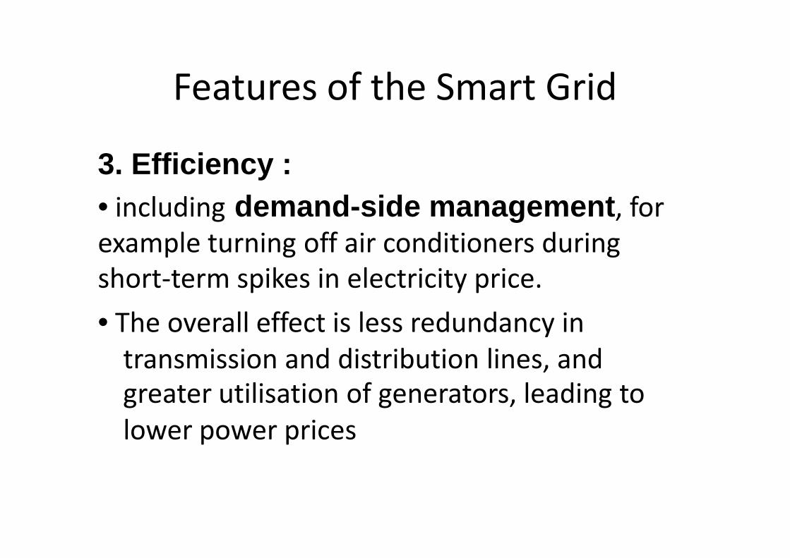
Features of the Smart Grid
3. Efficiency :• including demand -side managementexample turning off air conditioners during
short-term spikes in electricity price.
• The overall effect is less redundancy in
transmission and distribution lines, andtransmission and distribution lines, and
greater utilisation of generators, leading to
lower power prices
Features of the Smart Grid
side management , for
example turning off air conditioners during
term spikes in electricity price.
The overall effect is less redundancy in
transmission and distribution lines, andtransmission and distribution lines, and
greater utilisation of generators, leading to

Features of the Smart Grid
4. Load adjustmentUsing mathematical prediction algorithms it is• Using mathematical prediction algorithms it is
possible to predict how many standby generators
need to be used, to reach a certain failure rate.
• In the traditional grid, the failure rate can only be
reduced at the cost of more standby generators.
• In a smart grid, the load reduction by even a• In a smart grid, the load reduction by even a
small portion of the clients may eliminate the
problem.
Features of the Smart Grid
Using mathematical prediction algorithms it isUsing mathematical prediction algorithms it is
possible to predict how many standby generators
need to be used, to reach a certain failure rate.
In the traditional grid, the failure rate can only be
reduced at the cost of more standby generators.
In a smart grid, the load reduction by even aIn a smart grid, the load reduction by even a
small portion of the clients may eliminate the

Features of the Smart Grid
5. Peak curtailment/leveling and time of use pricin g• To reduce demand during the high cost peak usage• To reduce demand during the high cost peak usageperiods, communications and metering technologiesinform smart devices in the home and business whenenergy demand is high and track how much electricityis used and when it is used.
• It also gives utility companies the ability to reduceconsumption by communicating to devices directly inconsumption by communicating to devices directly inorder to prevent system overloads.
Features of the Smart Grid
5. Peak curtailment/leveling and time of use pricin gTo reduce demand during the high cost peak usageTo reduce demand during the high cost peak usage
periods, communications and metering technologiesinform smart devices in the home and business whenenergy demand is high and track how much electricity
It also gives utility companies the ability to reduceconsumption by communicating to devices directly inconsumption by communicating to devices directly inorder to prevent system overloads.

Features of the Smart Grid
6. Demand response support : generators and loads to interact in angenerators and loads to interact in anautomated fashion in real time, coordinatingdemand to flatten spikes.
7. Platform for advanced services : monitoring and alarms that can shut offmonitoring and alarms that can shut offpower, make phone calls to emergencyservices, etc.
Features of the Smart Grid
6. Demand response support : allowsgenerators and loads to interact in angenerators and loads to interact in anautomated fashion in real time, coordinatingdemand to flatten spikes.
7. Platform for advanced services : such as firemonitoring and alarms that can shut offmonitoring and alarms that can shut offpower, make phone calls to emergency


Electric Vehicle Charging
WHY ???
Electric Vehicle Charging
WHY ???
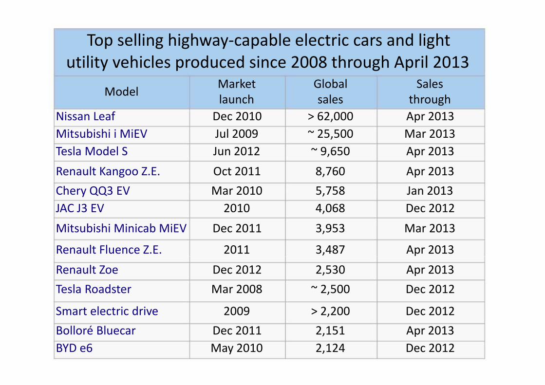
Top selling highway-capable electric cars and light
utility vehicles produced since 2008 through April 2013
ModelMarket
launch
Nissan Leaf Dec 2010
Mitsubishi i MiEV Jul 2009Mitsubishi i MiEV Jul 2009
Tesla Model S Jun 2012
Renault Kangoo Z.E. Oct 2011
Chery QQ3 EV Mar 2010
JAC J3 EV 2010
Mitsubishi Minicab MiEV Dec 2011
Renault Fluence Z.E. 2011Renault Fluence Z.E. 2011
Renault Zoe Dec 2012
Tesla Roadster Mar 2008
Smart electric drive 2009
Bolloré Bluecar Dec 2011
BYD e6 May 2010
capable electric cars and light
utility vehicles produced since 2008 through April 2013Global Sales
sales through
> 62,000 Apr 2013
~ 25,500 Mar 2013~ 25,500 Mar 2013
~ 9,650 Apr 2013
8,760 Apr 2013
5,758 Jan 2013
4,068 Dec 2012
3,953 Mar 2013
3,487 Apr 20133,487 Apr 2013
2,530 Apr 2013
~ 2,500 Dec 2012
> 2,200 Dec 2012
2,151 Apr 2013
2,124 Dec 2012

By Country
• Japan : 28,000, (July 2009
• United States : 27,000 (2008
By Country
Japan : 28,000, (July 2009 -Dec2012)
Nissan Leaf
operating as a
taxi in Japan
United States : 27,000 (2008 -Dec 2012)
The Tesla Model S in the second
best selling all-electric car in the
U.S.

By Country
• China : 27,800
QQ3 EV city car, with 5,305 units sold, followed
by the JAC J3 EV
• France : 14,600 (Jan 2010
Toyota Prius PHV with 413 registrations and
the Opel Ampera with 190the Opel Ampera with 190
By Country
, with 5,305 units sold, followed
14,600 (Jan 2010 - Dec 2013)
with 413 registrations and
the Opel Ampera with 190the Opel Ampera with 190

By Country
• Noway : 10,005
Norway has the largest electric car ownership per
capita in the world. Shown a
a REVAi and aTh!nk City at a free parking and
charging station in Oslo.
By Country
Norway has the largest electric car ownership per
capita in the world. Shown a Tesla Roadster,
at a free parking and
By Country
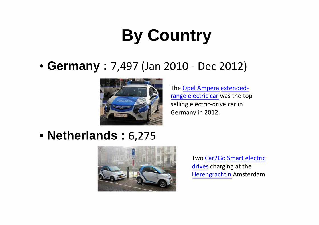
• Germany : 7,497 (Jan 2010
• Netherlands : 6,275
By Country
7,497 (Jan 2010 - Dec 2012)
The Opel Ampera extended-
range electric car was the top
selling electric-drive car in
Germany in 2012.
Two Car2Go Smart electric
drives charging at the
Herengrachtin Amsterdam.
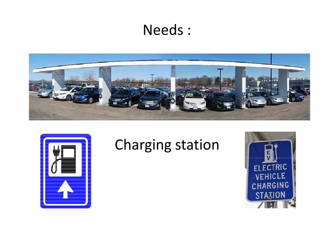
Needs :
Charging station
Needs :
Charging station

Electric Vehicle Charging Station• Dec 2012 : 50,000 non-residential slow charging points and
2,000 fast charges in the U.S., Europe, Japan and China.2,000 fast charges in the U.S., Europe, Japan and China.
• United States = 5,678 public charging stations across thecountry with 16,256 public charging points (March 2013)
• Europe: 15,000 charging stations (Nov 2012)
• Norway = 4,029 charging points and 127 quick chargingstations (March 2013)
• Japan = 1,381 public quick-charge stations and only around300 slow chargers (Dec 2012)
• Japan = 1,381 public quick-charge stations and only around300 slow chargers (Dec 2012)
• China = 800 public slow charging points, and no fastcharging station (Dec 2012)
Electric Vehicle Charging Stationresidential slow charging points and
2,000 fast charges in the U.S., Europe, Japan and China.2,000 fast charges in the U.S., Europe, Japan and China.
United States = 5,678 public charging stations across thecountry with 16,256 public charging points (March 2013)
Europe: 15,000 charging stations (Nov 2012)
Norway = 4,029 charging points and 127 quick charging
charge stations and only around300 slow chargers (Dec 2012)
charge stations and only around300 slow chargers (Dec 2012)
China = 800 public slow charging points, and no fast
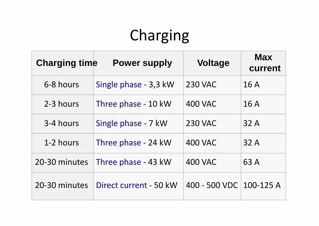
Charging
Charging time Power supply
6-8 hours Single phase - 3,3 kW
2-3 hours Three phase - 10 kW
3-4 hours Single phase - 7 kW
1-2 hours Three phase - 24 kW
20-30 minutes Three phase - 43 kW
20-30 minutes Direct current - 50 kW
Charging
Power supply VoltageMax
current
3,3 kW 230 VAC 16 A
10 kW 400 VAC 16 A
7 kW 230 VAC 32 A
24 kW 400 VAC 32 A
43 kW 400 VAC 63 A
50 kW 400 - 500 VDC 100-125 A
International Electrotechnical
Commission (IEC)
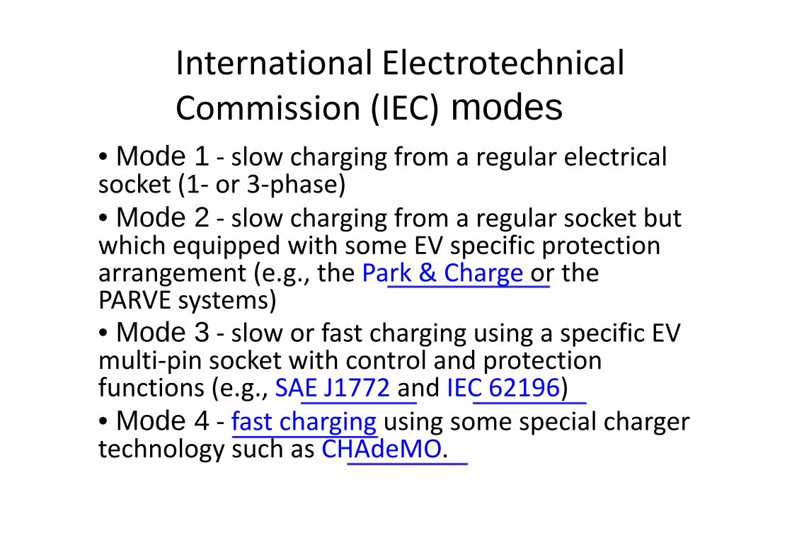
• Mode 1 - slow charging from a regular electricalsocket (1- or 3-phase)socket (1- or 3-phase)
• Mode 2 - slow charging from a regular socket butwhich equipped with some EV specific protectionarrangement (e.g., the Park & ChargePARVE systems)
• Mode 3 - slow or fast charging using a specific EVmulti-pin socket with control and protectionfunctions (e.g., SAE J1772multi-pin socket with control and protectionfunctions (e.g., SAE J1772
• Mode 4 - fast charging using some special chargertechnology such as CHAdeMO
International Electrotechnical
Commission (IEC) modesslow charging from a regular electrical
slow charging from a regular socket butwhich equipped with some EV specific protection
Park & Charge or the
slow or fast charging using a specific EVpin socket with control and protection
and IEC 62196)pin socket with control and protection
and IEC 62196)
using some special chargerCHAdeMO.

Mode 1
• Household socket and extension cord
• No dedicated circuit
• 10 A will take nearly 10 hours to fully charge• 10 A will take nearly 10 hours to fully charge
• Overcurrent Protective CB
• Temperature Cable
Mode 1
Household socket and extension cord
10 A will take nearly 10 hours to fully charge10 A will take nearly 10 hours to fully charge
Overcurrent Protective CB

Mode 2
• Domestic socket and cable with a protection
devicedevice
• A protection device is built into the cable.• A protection device is built into the cable.
• This solution is particularly expensive due to
the specificity of the cable.
Mode 2
Domestic socket and cable with a protection
A protection device is built into the cable.A protection device is built into the cable.
This solution is particularly expensive due to
the specificity of the cable.

Mode 3
• Specific socket on a dedicated circuit
• A control and protection function is also
installed permanently in the installationinstalled permanently in the installation
• meets the applicable standards
Mode 3
Specific socket on a dedicated circuit
A control and protection function is also
installed permanently in the installationinstalled permanently in the installation
meets the applicable standards

Mode 4
• Direct current (DC) connection for fast recharging
• connected to the main power grid through anexternal charger.
• Control and protection functions and the vehicle• Control and protection functions and the vehiclecharging cable are installed permanently in theinstallation.
Mode 4
Direct current (DC) connection for fast recharging
connected to the main power grid through an
Control and protection functions and the vehicleControl and protection functions and the vehiclecharging cable are installed permanently in the
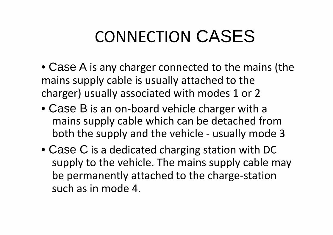
CONNECTION
• Case A is any charger connected to the mains (themains supply cable is usually attached to themains supply cable is usually attached to thecharger) usually associated with modes 1 or 2
• Case B is an on-board vehicle charger with amains supply cable which can be detached fromboth the supply and the vehicle
• Case C is a dedicated charging station with DCsupply to the vehicle. The mains supply cable maysupply to the vehicle. The mains supply cable maybe permanently attached to the chargesuch as in mode 4.
CONNECTION CASES
is any charger connected to the mains (themains supply cable is usually attached to themains supply cable is usually attached to thecharger) usually associated with modes 1 or 2
board vehicle charger with amains supply cable which can be detached fromboth the supply and the vehicle - usually mode 3
is a dedicated charging station with DCsupply to the vehicle. The mains supply cable maysupply to the vehicle. The mains supply cable maybe permanently attached to the charge-station
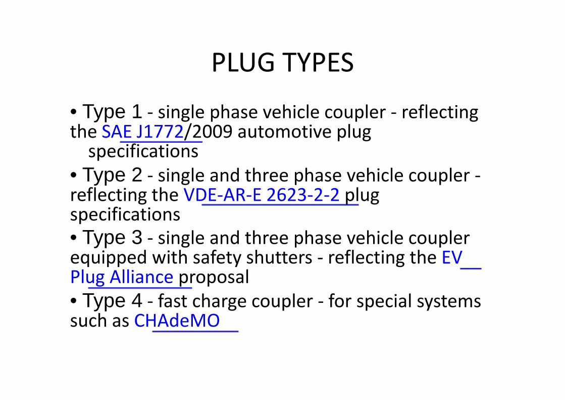
PLUG TYPES
• Type 1 - single phase vehicle coupler the SAE J1772/2009 automotive plugthe SAE J1772/2009 automotive plug
specifications
• Type 2 - single and three phase vehicle coupler reflecting the VDE-AR-E 2623specifications
• Type 3 - single and three phase vehicle couplerequipped with safety shutters Plug Alliance proposalequipped with safety shutters Plug Alliance proposal
• Type 4 - fast charge coupler such as CHAdeMO
PLUG TYPES
single phase vehicle coupler - reflecting/2009 automotive plug/2009 automotive plug
single and three phase vehicle coupler -E 2623-2-2 plug
single and three phase vehicle couplerequipped with safety shutters - reflecting the EVequipped with safety shutters - reflecting the EV
fast charge coupler - for special systems

SMART GRID COMMUNICATION
• Recharging a large battery pack presents ahigh load on the electrical gridhigh load on the electrical grid
• can be scheduled for periods of reduced loador reduced electricity costs
• Vehicle battery can supply energy to the gridat periods of peak demand
• requires additional communication between• requires additional communication betweenthe grid, charging station, and vehicleelectronics
SMART GRID COMMUNICATION
Recharging a large battery pack presents ahigh load on the electrical gridhigh load on the electrical grid
can be scheduled for periods of reduced loador reduced electricity costs
Vehicle battery can supply energy to the gridat periods of peak demand
requires additional communication betweenrequires additional communication betweenthe grid, charging station, and vehicle

SMART GRID COMMUNICATION
• SAE J2847/1 "Communication between Plug
in Vehicles and the Utility Grid". (by Society ofin Vehicles and the Utility Grid". (by Society of
Automobile Engineers )
• ISO and IEC are also developing a similar series
of standards known as ISO/IEC 15118
SMART GRID COMMUNICATION
SAE J2847/1 "Communication between Plug-
in Vehicles and the Utility Grid". (by Society ofin Vehicles and the Utility Grid". (by Society of
ISO and IEC are also developing a similar series
of standards known as ISO/IEC 15118

J2847: The New “Recommended Practice”
for High-Level Communication
ZigBee Smart Energy
J2847: The New “Recommended Practice”
Level Communication
ZigBee Smart Energy

Smart ChargerSmart Charger

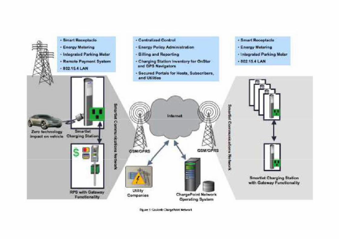
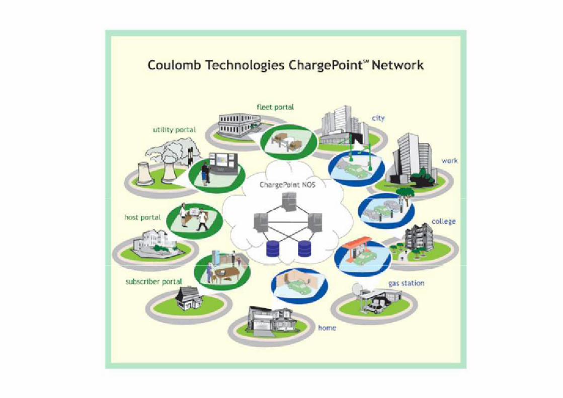
Electric Vehicle Charging Station LocationsElectric Vehicle Charging Station Locations
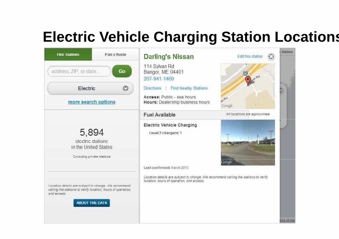
Electric Vehicle Charging Station LocationsElectric Vehicle Charging Station Locations
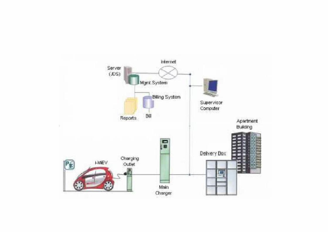
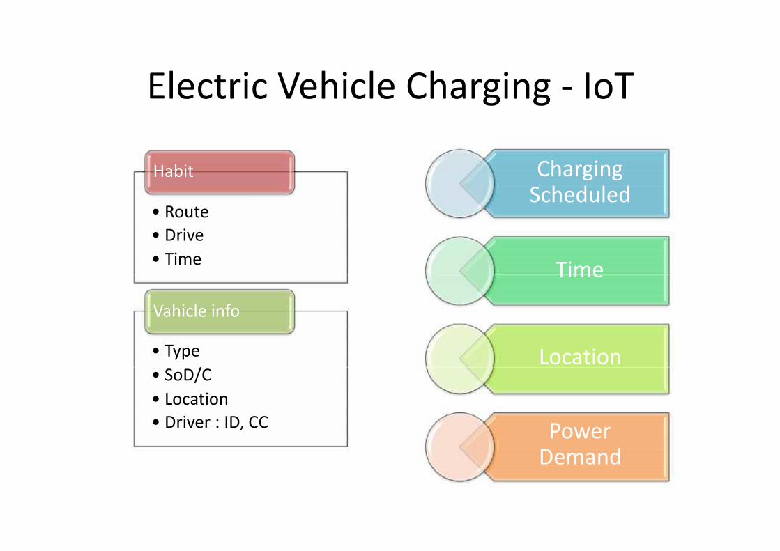
Electric Vehicle Charging
Habit
• Route
• Drive
• Time
Vahicle info
• Type
• SoD/C• SoD/C
• Location
• Driver : ID, CC
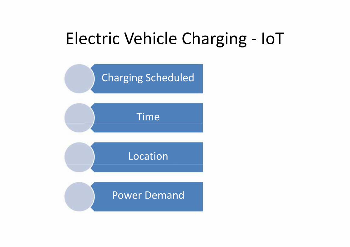
Electric Vehicle Charging - IoT
ChargingScheduledScheduled
Time
LocationLocation
PowerDemand
Electric Vehicle Charging
Charging ScheduledCharging Scheduled
Time
Location
Power Demand
Electric Vehicle Charging - IoT
Charging ScheduledCharging Scheduled
Power Demand

M2M CommunicationM2M Communication
Thank youThank you