shiplinktm to support your performance: cable solutions ... offer_bd.pdf · shiplinktm to support...
TRANSCRIPT

SHIPLINKTM to support your performance:cable solutions and services for safety and reliability
Exe17_NEXANS_catal_MARINE_avril2013 14/05/13 18:58 Page1

Exe17_NEXANS_catal_MARINE_avril2013 14/05/13 18:58 Page2

3
EMI
ClBrF
CClClClClClClCBrBrBrBrBrBrrFFFFFFF
r
TemperatureAdmissible ambient temperature for continuous duty operation
WeatherResistance to severe weather conditions
Fire PerformancesFire performance according to:
• «Flame retardant»IEC 60332-1
• «Fire retardant»IEC 60332-3-22 (for category A)IEC 60332-3-23 (for category B)IEC 60332-3-24 (for category C)IEC 60332-3-25 (for category D)
• «Fire resistant» IEC 60331-21IEC 60331-1 or 2
Halogen Free
Smoke-Corrosivity-ToxicitySmoke density, gases corrosivity and toxicity
Flexibility
Minimum Bending RadiusMBR = n x outer diameter
Electro Magnetic Interference
Water tight
Symbols
Cop
yrig
ht ©
Apr
il 20
13 -
Nex
ans
Exe17_NEXANS_catal_MARINE_avril2013 14/05/13 18:58 Page3

Instrumentation & Control cables
MPRX® 150/250 (300) V 90°C 78MPRXCX® 150/250 (300) V 90°C 80TX® (C) 150/250 (300) V 90°C 82TX® (I) 150/250 (300) V 90°C 84TCX® (C) 150/250 (300) V 90°C 86TCX® (I) 150/250 (300) V 90°C 88TX® (C) 331 150/250 (300) V 90°C 90TX® (I) 331 150/250 (300) V 90°C 92TCX® (C) 331 150/250 (300) V 90°C 94TCX® (I) 331 150/250 (300) V 90°C 96
1 - Power cables 92 - Control & instrumentation cables 113 - Communication cables 124 - Fire performance 175 - Pulling & installation 206 - Electrical parameters 227 - Electrical parameters for instrumentation cables 268 - Nexans Services 28
Shipboard cables
Generalities
Shipboard cables
Page
Medium voltage cables
Cables Voltage Operating temperature Page
Power & Control cables
MPRX® 0.6/1 (1.2) kV 90°C 52MPRXCX® 0.6/1 (1.2) kV 90°C 56MPRX® FLEXISHIP® 0.6/1 (1.2) kV 90°C 60MPRXCX® FLEXISHIP® 0.6/1 (1.2) kV 90°C 62MPRX(ST)X 0.6/1 (1.2) kV 90°C 64MPRX® 331 0.6/1 (1.2) kV 90°C 66MPRXCX® 331 0.6/1 (1.2) kV 90°C 68 MPRX(ST)X 331 0.6/1 (1.2) kV 90°C 70MPRX® 331 FLEXISHIP® 0.6/1 (1.2) kV 90°C 72MPRXCX® 331 FLEXISHIP® 0.6/1 (1.2) kV 90°C 74
MPRXCX® & MPRXCX® FLEXISHIP® 1.8/3 (3.6) kV 90°C 32MPRXCX® 3.6/6 (7.2) kV - 6/10 (12) kV 90°C 34MEPRXCX® 8.7/15 (17.5) kV - 12/20 (24) kV 90°C 36MPRXCX® FLEXISHIP® 3.6/6 (7.2) kV - 6/10 (12) kV - 90°C 38MEPRXCX® FLEXISHIP® 8.7/15 (17.5) kV - 12/20 (24) kV 90°C 40MMGSHXCHX & MMGSEHXCHX 6/10 (12) kV 90°C 42MMGSHX & MMGSEHX 6/10 (12) kV - 8.7/15 (17.5) kV 90°C 44E.T.I. Terminaison 6/10 (12) kV - 8.7/15 (17,5) kV 48
- 12/20 (24) kV
4
Exe17_NEXANS_catal_MARINE_avril2013 14/05/13 18:58 Page4

MX Wiring Cables 0.6/1 (1.2) kV 90°C 124MPRXCX® EMC & MPRXCX® FLEXISHIP® EMC 0.6/1 (1.2) kV 90°C 126MPRXCX® FLEXISHIP® EMC 1.8/3 (3.6) kV 90°C 126MPRX® CAB 300/500 V 90°C 128MPRX® F 0.6/1 (1.2) kV 90°C 130BMKHC (I) 150/250 (300) V 90°C 132CCTV composite 134
5
Communication cables
Cables Voltage Temperature Page
Specific Application cables
COAX FLAMEX - RG serie 50 Ω / 75 Ω 70°C 100COAX FLAMEX - KX serie 50 Ω / 75 Ω 70°C 102PROFIBUS 150 Ω 85°C 104CAN BUS CABLES 120 Ω 70°C 106LAN SF/UTP Category 6 Cables 108LAN F/UTP Category 5e Cables 110LAN S/FTP Category 7 Cables 112LAN CABLING 114LANmark LSZH 116Optical Fiber cables 118BREAKOUT CABLES 120
Type approvalsNexans Shipboard cables are approved by certification bodies in accordance with their rules and regulations forclassification of ships: • DNV (Det Norge Veritas)• GL (Germanischer Lloyd)• LRS (Lloyd register of Shipping)• BV (Bureau Veritas)• ABS (American Bureau of Shipping)• RINA (Registro Italiano Navale)For updated type approvals, please consult our web site: www.nexans.com/shipbuilding (a login is required)
Cop
yrig
ht ©
Apr
il 20
13 -
Nex
ans
Exe17_NEXANS_catal_MARINE_avril2013 14/05/13 18:58 Page5

Exe17_NEXANS_catal_MARINE_avril2013 14/05/13 18:58 Page6

7
Cop
yrig
ht ©
Apr
il 20
13 -
Nex
ans
GEN
ERA
LITIE
S
Part 1Generalities
Exe17_NEXANS_catal_MARINE_avril2013 14/05/13 18:58 Page7

8
Designing and building modern vessels as: Cruiseships, LNG Tankers, Container ships, FPSOs,specialized and offshore support vessels, is a complexprocess.
The perfect integration of electrical modules willneed performing and easy to install electricalcables.
Nexans has designed a groundbreaking range ofcables which will bring advanced electrical andmechanical performances to shipyards, electricalinstallers and naval engineering and consultants.
Nexans cables bring outstanding benefits andadvantages as: Easy installation, enhanced flexibility,easy pulling, easy connecting & stripability, reducedsize and weight.
Outstanding performances: halogen free, extremeresistance to: Fire, paint, EMC, crush, cold and thermal.
In addition, thanks to its customer orientedapproach, Nexans has developped a very efficientlogistic service and cable management able to servethe most stringent delivery time and requirements.
Exe17_NEXANS_catal_MARINE_avril2013 14/05/13 18:58 Page8

For different length, or other air ambient temperature, the electrical resistance can be calculatedwith the formula:
Rt = R20 x L / Ktwhere
Rt (Ohm/km) Electrical resistance in DC at a temperature t in °C for a length L (km).R20 (Ohm/km) Maximum electrical resistance value in DC given in the IEC60228 at 20°C.Kt Correction temperature factor given in the following table and depending on the
room air ambient temperature.
Shipboard cables manufactured by Nexans are designed for fixed applications on board of commercial or navy vessels.Depending on the mechanical risk exposition, 2 various ranges are proposed:• Un-armoured cables with MPRX® designation• Armoured cables with MPRXCX® designation
1-1 Conductor:All conductors integrated in Nexans shipboard cables are strictly compliant with the International ElectricalCommittee IEC 60228 Standard. Depending on the application, vessel manufacturers have to choose conductorsflexibility, and also, eventually copper protection against corrosion or chemical attack by using tin coated copper.IEC 60228 specifies different maximum electrical resistance values for each nominal cross section area, both inclass 2 or class 5 conductors, and in bare or tinned copper.In the table below, these values in Ohm/km are given for DC measurement (direct current) at the normativetemperature of 20°C.
9
1 – POWER CABLES
Power copper conductors according to IEC 60228
1.5 7 12.1 12.22.5 7 7.41 7.564 7 4.61 4.706 7 3.08 3.11
10 7 1.83 1.8416 7 1.15 1.1625 7 or 19 0.727 0.73435 7 or 19 0.524 0.52950 19 or 37 0.387 0.39170 19 or 37 - 52 0.268 0.27095 19 or 37 - 61 0.193 0.195
120 37 or 61 0.153 0.154150 37 or 61 0.124 0.126185 37 or 61 0.0991 0.100240 61 or 61 0.0754 0.0762300 61 or 61 0.0601 0.0607
0.26 13.3 13.70.26 7.98 8.210.31 4.95 5.090.31 3.30 3.390.41 1.91 1.950.41 1.21 1.240.41 0.780 0.7950.41 0.554 0.5650.41 0.386 0.3930.51 0.272 0.2770.51 0.206 0.2100.51 0.161 0.1640.51 0.129 0.1320.51 0.106 0.1080.51 0.0801 0.08170.51 0.0641 0.0654
Cross section(mm2) Number
of wires
DC Maximum Resistance at 20°C(Ohm/km)
Bare copper Tinned copper
Class 2
Max. diameter of wires inconductor
DC Maximum Resistance at 20°C(Ohm/km)
Bare copper Tinned copper
Class 5
Cop
yrig
ht ©
Apr
il 20
13 -
Nex
ans
GEN
ERA
LITIE
S
Exe17_NEXANS_catal_MARINE_avril2013 14/05/13 18:58 Page9

10
1-2 Insulation:Nexans has selected Halogen Free XLPE (cross linked polyethylene) compound for all power LV and MV cables up to 6/10 kV,and Halogen Free EPR (ethylene propylene rubber) for MV cables with 8.7/15 kV or 12/20 kV voltages.All material characteristics: electrical, mechanical and chemical are complying with the requirements of IEC 60092-351.For fire resistant cables, Nexans has chosen the new INFITTM technology HF 90 or S95 in IEC 60092-351 that brings manyinstallation advantages, as easy stripping insulation.HF XLPE and HF EPR compounds can be used for a permanent conductor temperature of 90°C; that corresponds to a lifetime of more than 40 years (Arrhenius ageing curve).These cross linked compounds can also accept a 250°C temperature in case of short circuit.
1-3 Armour:On board, mechanical risk on cables is quite usual in unprotected spaces, it is the reason why most of them are armoured.As cable weight is important, and is aimed to be minimized, steel tapes or steel wires armour are not used, preference isgiven to metal braid.That is the best compromise between mechanical protection, weight and installation facility.For all ranges of shipboard cables, Nexans has chosen copper braid armour that also can be used as a screen and anelectro magnetic protection.Generally, bare copper braid is used on the commercial vessels.Tinned copper braid armour is only required in offshore projects where hydrogen sulphide can corrode the bare copper.
1-4 Sheath:Outer sheath is the final protection of the cable. Depending on the cable environment, outer sheath compound must satisfyperformances as extreme temperature, solar radiations, oil, grease and various aggressive substances. IEC 60092-359 standard specifies performance values to different tests for 2 sheathing material families: SHF1 forthermoplastic compounds, and SHF2 for thermosetting compounds.Of course, these materials are halogen free, low smoke density, low gas toxicity and low gas acidity.For the main ranges of stocked products, Nexans has chosen its own SHF1 compound that offers a good compromise ofperformances (cold behaviour + oil drops resistance at ambient temperature). For permanent oil contact, SHF2 compoundis recommended.
Correction factors according to IEC 60228
IEC 60228 standard provides electrical resistance of copper conductors at an ambient temperature of 20°C.For other temperatures, correction factors are applied as below:
5 1.06410 1.04215 1.02020 1.00025 0.98030 0.96235 0.94340 0.92645 0.90950 0.89355 0.87760 0.86265 0.84770 0.83375 0.82080 0.80685 0.79490 0.78195 0.769
100 0.758
Temperature (°C) Kt
Exe17_NEXANS_catal_MARINE_avril2013 14/05/13 18:58 Page10

11
Instrumentation and control conductors in accordance with IEC 60092-376
Cross section(mm2) Number
of wires
DC Maximum Resistance at 20°C (Ohm/km)
Bare copper Tinned copper
Class 2
0.50 7 40.4 41.60.75 7 26.0 26.31.00 7 19.2 19.31.50 7 12.8 12.92.50 7 7.86 8.02
2 – CONTROL & INSTRUMENTATION CABLES
Shipboard cables manufactured by Nexans are designed for fixed applications for circuits rated at 150/250 V,and are complying with IEC 60092-376 standard.Multi-cores cables are mainly dedicated for control, and multi pairs, triples or quads are for instrumentation devices.When required, circuit integrity in fire is made by using fire resistant cables complying with IEC 60331 fire tests.Control and Instrumentation cables are proposed in versions:• Un-armoured: MPRX®/MPRX 331® for control or TX®/TX 331® for instrumentation.• Armoured: MPRXCX®/MPRXCX 331® for control or TCX®/TCX 331® for instrumentation.
TX® and TCX® ranges are designed with individual screen over each unit (I) or collective screen over theassembly of units (C).
2-1 Conductor:Tinned or bare copper, class 2 stranded conductors with 7 wires are generally required for control andinstrumentation links.Nominal cross section areas are: 0.5 – 0.75 – 1 – 1.5 and 2.5 mm² .Due to assembly length factor for large number of unit, electrical resistance are not strictly in accordance with IEC60228, but electrical resistance values are complying with IEC 60092-376 as indicated in the following table:
2-2 Insulation:As for the power cables, Nexans‘s choice is for XLPE compound that offers the best compromise in terms ofmechanical and electrical properties.XLPE compound has also a low permittivity value about 2.3. For fire resistant cables, the new INFITtTM technology (HF 90 compound in IEC 60092-351) has been chosen.
2-3 Cabling:For instrumentation range, in adjacent units, different cores lay lengths are selected, in order to reduce inductiveeffects and cross-talks.All units are assembled in concentric layers.
2-4 Electrostatic ScreenIndividual (I) or/and Collective (C):
Laminated aluminium bonded to polyester tape with a tinned drain wire is generally used as electrostatic screenwith a minimum overlap of 25% of the tape width.Copper braid is also allowed to be used as screening as stated in IEC 60092-376.
2-5 Armour:As for power cables, armour is made of tinned or bare copper braid. For instrumentation TCX® (C) range, the armour is also used to provide the function of a collective screen.
2-6 Sheath:SHF1 or SHF2 Sheathing compounds are in accordance with IEC 60092-359 standard.
Cop
yrig
ht ©
Apr
il 20
13 -
Nex
ans
GEN
ERA
LITIE
S
Exe17_NEXANS_catal_MARINE_avril2013 14/05/13 18:58 Page11

12
3 – COMMUNICATION CABLES
Communication cables include Coaxial, Fieldbus, LAN copper pairs and optical fibres cables.
3-1 COAXIAL cables:Main characteristic of this family is Impedance that could be 50 Ohms or 75 Ohms.MIL-C-17 Coaxial cables are usually used for onboard high frequency data transmission (communicationequipment, radar, and instrumentation) and also carry video signals for surveillance cameras. FLAMEX® RG offersexceptional fire safety in single cable.A coaxial cable is often combined with various conductors in a compact hybrid cable for piloting and poweringCCTV cameras.
3-2 FIELDBUS cables:These Halogen-Free Flame and Fire-Retardant cables are dedicated to maritime applications. They have fixedimpedance and transmit an extremely precise digital signal to control all essential shipboard functions, like motors,rudder and hydraulic systems.Can Bus cable comes in a single or double pair; while Profibus cable is a single pair and both can be suppliedwith SHF1 or SHF2 outer sheath depending on specification.Adapted from the industrial plant environment, these high performance cables are fully sea resistant and canoperate safely in temperatures from -20°C to +70°C.
3-3 LAN (Local Area Network) copper cables:Several categories (Cat 5, Cat 6 and Cat 7) cables designed in 4 pairs are dedicated for high frequency signaland high rate transmissions.
3-4 OPTICAL FIBRE cables:General OverviewOptical fibers are mainly used to transmit information over long distances and with high bit rates. Their benefits arenumerous: the signal transmitted on the fiber is not disturbed by any electromagnetic wave created by power cablesor electric machines. It also provides more security, as these cables can be fully dielectric. Besides, theyprovide a weight and space saving due to their small diameter, only 250 µm. An optical fiber is made up of three main parts: the core, the cladding and the coating.In the center, the “core” is made of doped silica and is surrounded by the “cladding”, made of natural silica.The light signal propagates along the core and the signal is reflected on the surface between the core and the cladding.An acrylic “coating”, generally made of two layers, is protecting the sillica part against abrasion during installation.
Coating
Cladding
Core
Exe17_NEXANS_catal_MARINE_avril2013 14/05/13 18:58 Page12
13
Multimode fibers
125 µm
62.5 µm 50 µm 9 µm
62.5/125
Singlemode fiber
50/125 9/125
125 µm125 µm{ {
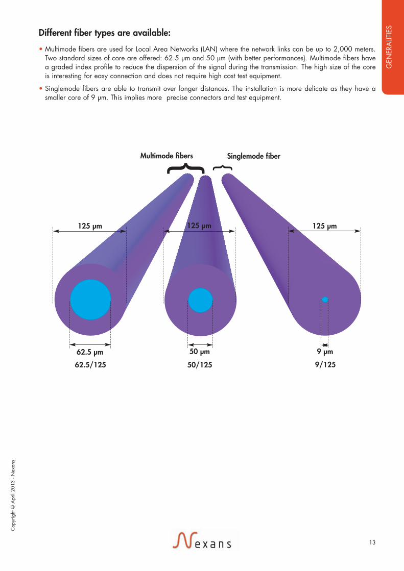
Different fiber types are available:
• Multimode fibers are used for Local Area Networks (LAN) where the network links can be up to 2,000 meters.Two standard sizes of core are offered: 62.5 µm and 50 µm (with better performances). Multimode fibers havea graded index profile to reduce the dispersion of the signal during the transmission. The high size of the coreis interesting for easy connection and does not require high cost test equipment.
• Singlemode fibers are able to transmit over longer distances. The installation is more delicate as they have asmaller core of 9 µm. This implies more precise connectors and test equipment.
Cop
yrig
ht ©
Apr
il 20
13 -
Nex
ans
GEN
ERA
LITIE
S
Exe17_NEXANS_catal_MARINE_avril2013 14/05/13 18:58 Page13

14
On a global network point of view, although the cost of multimode fiber is more important than the singlemode’s,the complete system is more economic. Indeed Multimode fibers are used with cheap transmission componentsLED(1) or VCSEL(2) whilst Singlemode fiber operates with more expensive LASER.(1) LED: Light Emitting Diode(2) VCSEL: Vertical Cavity Surface Emitting Laser
Optical fibers are used at specific wavelength. Multimodes fibers are mainly used at 850 nm and 1,300 nm andSinglemode are used at 1,310 nm and 1,550 nm. The attenuation performances are better at the higher bandwidthwith consequently improved transmission performances.
Optical fiber can be provided with different characteristics. Indeed the performance need for fiber in patch cordor fiber over one kilometer link are obviously different. The fiber choice is based on optical parameters such asattenuation, bandwidth performances and chromatic dispersion.
Different international standards are available to describe the optical fiber characteristics: ITU G652 forSinglemode fiber and IEC 60793-2-10 for Multimode fibers are worldwide references.
© P
hoto
grap
her F
lyin
g Fo
cus
Exe17_NEXANS_catal_MARINE_avril2013 14/05/13 18:58 Page14

Optical characteristics
15
Core diameter 9.0 ± 0,5 µm 50 ± 3 µm 62.5 ± 3 µm
Cladding diameter 125 ± 2 µm
Coating diameter 245 ± 10 µm
Numeral aperture 0.200 ± 0.015 0.275 ± 0.015
Attenuation:
850 nm ≤ 2.8 dB/km ≤ 3.4 dB/km
1300 nm ≤ 1.0 dB/km ≤ 1.1 dB/km
1550 nm ≤ 0.6 dB/km
Brandwidth at:
850 nm - ≥ 600MHz ≥ 200MHz
1300 nm - ≥ 1200MHz ≥ 600MHz
Dispersion at:
1310 nm < 3.5 ps/nm
1550 nm < 18 ps/nm
Index of reflaction (IOR) at:
850 nm 1.482 1.496
1300 nm 1.477 1.491
1310 nm 1.4677
1550 nm 1.4682
Geometrical characteristics
... E9/125 ... G50/125
Technical fibers properties
... G62.5/125
Fiber types
Cop
yrig
ht ©
Apr
il 20
13 -
Nex
ans
GEN
ERA
LITIE
S
Exe17_NEXANS_catal_MARINE_avril2013 14/05/13 18:58 Page15

16
Optical fiber connectors
Nexans are able to preassembleoptical fibers with plugs, we canprovide this service in our factoryor on site. A fiber optic connectoris a non permanent join betweentwo fibers.
Standard fiber connectorsmay be used, as e.g. ST, SC,FC and LC connectors
ST Connector (standard)
This type of connector is suitablefor both multimode fiber andsinglemode fiber. The ST connectorand the bajonet-holder is the mostpopular used connectorworldwide.
To achieve the best possibletransfer of light signalbetween fibers, higherquality connector is requiredas E2000 or MT-RJ that isused for fiber modemapplications.
E2000 Connector
An E2000 connector is a specialconnector with high levelattenuation coefficient. Thisconnector is suitable for multimodefiber and singlemode fiber.
Due to the code system, thisconnector is very user friendly andcan also be fit as a singleconnector or duplex connector
The built-in filler cap protects theferrule against contamination. Thefiller cap open/close during theconnector plug in/out.
© S
TX E
urop
e
Exe17_NEXANS_catal_MARINE_avril2013 14/05/13 18:58 Page16

17
4 – FIRE PERFORMANCENexans Research Center has adapted a program of constant improvement for insulation and sheathing materials,and cable designs.Some developments ensure fire performance characteristics for the Nexans shipboard cables range as flame andfire retardancy, smoke and fumes emission, fire resistance integrity and cable recycling after life time.Nexans shipboard cables are fully withstanding the requirements of the following IEC standards:
4-1 Flame retardancy: IEC 60332-1 Test on a single vertical insulated wire or cable
This simple test provides an adequate evaluation of the flameretardant characteristic of a single cable. Depending on thecable size (diameter and weight) a regulated flame iscontinuously applied for a calculated time to the cable.The test is passed if the cable has self extinguished and the burntportion of the cable has not reached the top of the sample.
4-2 Fire retardancy: IEC 60332-3Test on bunched wires or cables
Cables, when installed, vertically or horizontally laid,bunched on cable trays, in conduit or pipes, are potentialvectors for fire propagation.This test was developed to obtain a method to determinethe fire propagation characteristic of a group of bunchedcables fixed on a vertical 3.5 m ladder (see Part 10 –apparatus).The fire propagation along a bunch of cables depends on:• the volume of combustible exposed to fire• the geometrical configuration of the cables installation
(touching or spaced)• the temperature at which it is possible to ignite any
emitted gases from the cables• the quantity of combustible gas released from the cables• the volume of air passing through the cables installationNexans provides fire retardant IEC60092 seriesshipboard cables meeting the requirements of thegeneral standard Part 350 that specifies category 22 intouching configuration in one or more layers.IEC 60332-3 standard indicates 5 categories dependingon 2 parameters:• the volume of combustible material ( insulation, filler
and sheaths)• the duration of flame exposition ( 20 or 40 minutes)For specific and small cables (diameter < 12 mm), firetest is according to the new category (25 previously D)test category that needs less cable quantity.
Fire retardant test accordingto the IEC 60332-3-22 - Cables installed
in group on a vertical ladder
Flame Retardant IEC 60332-1
Test category
21 (A F/R) 7 4022 (A) 7 4023 (B) 3.5 4024 (C) 1.5 2025 (D) 0.5 20
Volume ofcombustible(litres/meter)
Time of flameapplication (min)
Cop
yrig
ht ©
Apr
il 20
13 -
Nex
ans
GEN
ERA
LITIE
S
Exe17_NEXANS_catal_MARINE_avril2013 14/05/13 18:58 Page17

18
4-3 Fire resistance: IEC 60331Test of fire resistance integrity of cables
In case of fire, some circuits must maintain the power supply for vital safety equipment as emergency lighting, alarmsystems, fire pumps… IEC 60331 standard determines the circuit integrity of a cable during and after a prolonged fire with different testequipments and test methods:• flame at 750°C temperature during 90 minutes applied to a horizontal cable under the nominal voltage
Part 11 - apparatus and Part 21 - procedure and requirements• flame at 850°C temperature during 90 minutes with shocks on the ladder support applied to a cable under the
nominal voltagePart 1 - for cable diameter > 20 mm,Part 2 - for cable diameter ≤ 20 mm
• for data cablesPart 23 - procedure and requirement
• for optical fiber cablesPart 25 - procedure and requirement
For electrical cables, tests are passed if no breakdown occurs (no failure of the fuses).Nexans proposes a large range: power, control and instrumentation of fire resistant shipboard cables.To meet these requirements, Nexans offers the traditional technology with lapped mica tape + extruded XLPEinsulation system; and has developed a specific INFITTM technology with HF90 and S95 extruded compounds. Thisnew insulation gives installation advantages: easier insulation stripping and secured connexions.
Fire resistant test accordingto IEC 60331 Part 11 & 21
Fire resistant test accordingto IEC 60331 Part 2
Fire resistant test accordingto IEC 60331 Part 1
Exe17_NEXANS_catal_MARINE_avril2013 14/05/13 18:58 Page18

19
4-4 Measurementsof combustion gases:IEC 60754 Part 1 & 2
Part 1: this test permits thedetermination of the amount ofhalogen gas emitted during thecombustion of the differentpolymeric compounds (insulation,filler, sheaths) taken from a cable.
Part 2: this test determinates thedegree of acidity of gases bymeasuring pH and conductivity.
4-5 Smoke density:IEC 61034(27 m3 chamber)
In case of fire; smoke emissionsconsiderably reduce the visibilityon board.
Passenger evacuation has to beheld in a very short time.Therefore materials used in shipsshould not spread a lot of opaquesmoke.
Nexans shipboard cables aredesigned to withstand therequirements of IEC 61034 basedon the 27 m3 test developed bythe London Transport ExecutiveResearch Laboratory.
This test permits to measure theopacity of smoke emitted from burningcables (light transmittance).
Part 1: apparatus including lightmeasurement, fire source, smokemixing method and qualificationprocedure
Part 2: procedure and requirements.
Measurements test equipmentof combustion gases according to the
IEC 60754-1/60754-2
Measurement of smoke opacity - 27m3 - Chamber
Cop
yrig
ht ©
Apr
il 20
13 -
Nex
ans
GEN
ERA
LITIE
S
Exe17_NEXANS_catal_MARINE_avril2013 14/05/13 18:58 Page19

20
5 – PULLING & INSTALLATIONIn order to reduce pulling and installation time, Nexans has designed a cable range which offers:• time saving on connexions by easy sheath and insulation stripping• reduced weight, diameter and volume• easier drawing due to low friction coefficient of polyolefin outer sheath compound.Nexans decides to distinguish main cable circuits by different outer sheath colours:• red for medium voltage cables (from 1.8/3 kV up to 12/20 kV)• black for power and control cables rated 0.6/1 kV• grey for instrumentation and control cables rated 150/250 V• orange for all types fire resistant cables• blue for intrinsic circuit cablesIn order to avoid unwanted effects of electromagnetic interference (EMI) as far as possible, Nexans recommends to separateon different cable trays, power circuits from control, instrumentation or communication circuits.
5-1 PullingThe process of pulling electrical cables on board of marine vessels is relatively a usual procedure. Nevertheless, Nexanswould suggest some following rules to avoid any cable degradation and damage. Prior to start, care must be taken to ensure that the pulling equipment directly attached to the cable is tightly fitted over thecomplete cable and not only to one cable element such as the outer sheath, armour or conductors.The maximum pulling force exerted on the cable must not exceed 50 N/mm² (of nominal cross section area of theconductors) whether the cable is being manually pulled or with a winch or other mechanical equipment.If the cable link is pre-cut before pulling, the cable has to be correctly coiled to avoid any over twist.Pre-cut cable ends, in waiting position before final installation and connexion must be protected.All cable runs must be smooth and clean or covered with a complementary protection to prevent any outer sheath damage.When several cables are pulled together, talcum is recommended to limit friction and abrasion between cables and to easethe pulling process with better cables sliding.Where cables have to be pulled perpendicularly to other cables already installed, it is advised to protect them to avoidabrasion damage.Cables have to be pulled with a slow and regular speed about 20 m/minute, and with a minimum outer temperatureof -15°C. It is always necessary, to store cables in warmed premises at an ambient temperature of + 10°C for 12 hours.A longer period might be necessary for large drums.
5-2 InstallationCables installation must be in accordance with certification Bodies rules, and also with IEC 60092-352 or IEC 61892-4.Some recommendations are given as follow about:• special precautions for single-core cables for A.C. wiring• minimum bending radius • parallel cable links • solar to sun rays in open areas .
5-2-1 Precautions for single-core cables:In order to reduce electro-dynamic forces when a short circuit appears, symmetric method for cable installation isrecommended as is shown in the following table (L1, L2 and L3 indicates the location of the respective phase conductor). See 1st template on opposite page.
5-2-2 Minimum bending radius:To limit the stress (elongation/compression) on insulation and sheath materials when cable are bent, rules aboutminimum internal bending radius have to be respected:• in fixed installations• during pulling and installation Values for these MBR stated in IEC 60092-352 and IEC 61892-4 are given in the following table.See 2nd template on opposite page.
Exe17_NEXANS_catal_MARINE_avril2013 14/05/13 18:58 Page20

5-2-3 Parallel cables link:According to certification society rules, several cables can be installed in parallel if certain conditions are respected:• cables type must be the same (same design) • cables must be rated for the same temperature class• cables must have the same nominal cross section areas• conductor cross section area > 10 mm²• cables must have equal lengths.
5-2-4 Exposure to the sun in open areas:Cables with black sheaths are intended for direct UV exposure. Cables with other sheath colors are sensitive to UV withoutimpact on the electrical functionality and the performances in terms of fire propagation and smoke emission.Nexans recommends to protect cables which are sensitive to UV by UV-proof hoods installed over those. When cables areinstalled in luminaries or lighting, specific protection of insulation and cables must be applied as required in IEC 60598.
L1 L2 L3 L3 L2 L1 2 6 or L1 L2 L3
L3 L2 L1
L1 L2 L33 9 L2 L3 L1
L3 L1 L2
L1 L2 L3 L3 L2 L1 L3 L2 L1 L1 L2 L3 or
4 12 L3 L1 L2 L3L2 L3 L1 L2L1 L2 L3 L1
Number of conductors perphase Recommended cable positionningNumber of single core
cables
21
Cables with circular class 2 conductors:outer diameter ≤ 25 mm 4D 6Douter diameter > 25 mm 6D 6D
Cables with sector shaped class 2 conductors 8D 8D
FLEXISHIP® cable with class 5 conductors 4D 5D(round or sector shaped conductors)
Single core cables - class 2 conductors 12D- FLEXISHIP® 10D
3 cores cables - class 2 conductors 9D - FLEXISHIP® 7.5D
Cables Type up to 1.8/3 kVMinimum internal bending radius
Unarmoured Cables Armoured Cables
Cables Type from 3.6/6 kV to 12/20 kV
All these bending radius values must be multiplied by 2, during pulling and installation of the cables.
Cop
yrig
ht ©
Apr
il 20
13 -
Nex
ans
GEN
ERA
LITIE
S
Exe17_NEXANS_catal_MARINE_avril2013 14/05/13 18:58 Page21

6 – ELECTRICAL PARAMETERSFor power, low voltage and medium voltage cables, cross section nominal areas are calculated in taking into account severalparameters as:• permissible current carrying capacities • voltage drop• short circuit values
6-1 Permissible current carrying capacities:Permissible current carrying capacities are stated by the rules of the vessel approval authority and in line with IEC 60092-352 and IEC 61894-4 standards.These values are applicable for DC and AC with a nominal frequency of 50 Hz or 60Hz.For higher frequency, current ratings shall be calculated with appropriate method.First, these values depend on the temperature class of the cable, and mainly on the maximum service temperature suitablefor the insulation compound. Nowadays, in shipbuilding industry, 90°C rated cables are mostly installed on board.Other important parameters are to be taken into account for the choice of the nominal cross section areas of conductors:• ambient temperature • mutual heating effect due to cables grouping• short time duty• solar radiation This catalogue gives only an extract of IEC 60092-352 standard that selected 2 methods for the determination of currentcarrying capacities for continuous service. These methods are derived from experimental data and from IEC 60287 (Electriccables- Calculation of current rating).
Method A: calculation with the formulaI = A S m – B S n whereI is the current rating capacity (in Ampere).S is the nominal cross section area of conductor (in mm²).A and B are coefficients, m and n are exponents according to cable type and method of installation.This method allows for greater choice of use in different installation configurations (see IEC 60092-352 and/or IEC 60364-5-52).
Method B: calculation with the formulaI = A S 0.625 whereI is the current rating capacity (in Ampere).S is the nominal cross section area of conductor (in mm²).A is a coefficient depending on the conductor temperature class, e.g. A = 18 for MPRX
and MPRXCX cables.The following table gives current carrying capacities in continuous service for 85°C and 90°C rated cables foran ambient air temperature of 45°C
22
1.5 21 18 152.5 28 24 204 38 32 276 49 42 34
10 67 57 4716 91 77 6425 120 102 8435 148 126 10450 184 156 12970 228 194 16095 276 235 193
120 319 271 223150 367 312 257185 418 355 293240 492 418 344300 565 480 396
Nominalcross-sectional area mm2
Current carrying capacitySingle core (A) 2 cores (A) 3 or 4 cores (A)
Conductor temperature: 85°C
Exe17_NEXANS_catal_MARINE_avril2013 14/05/13 18:58 Page22

23
6-1-2 Correction factor for cables groupingWhen cables are installed in group, due to thermal effect, a correction factor 0.85 must be applied to reduce the currentcarrying capacities.Current ratings are recommended as being applicable to both unarmoured and armoured cables laid in free air as a group of4 bunched together. These ratings may be considered applicable, without correction factors for a group of maximum 6 cablesbunched together on cable trays, operating simultaneously at their full rated capacity, without free air circulation around them.When, it is to be expected that air temperature around cables could be higher than 45°C (due to heat transfer or incompartments where heat is produced) the current rating given in the table shall be reduced.
6-1-3 Correction factor for short time dutyCorrection factor could be also applied to maximise current ratings when cables are operating during a short period(less than 1 hour).This factor depends on the cable time constant and also on the cable diameter.For more details, see IEC 60092-352.
6-1-4 Correction factor for U.V. solar radiationNexans recommends shielding cables from direct solar exposition. For cables with black or grey sheath, in case of solarradiation, a correction factors must be applied to the current carrying capacities given in the table :• 0.8 for black colour of outer sheath• 0.9 for light colour of outer sheath (e.g. light grey)Cables with other colors are not intended for direct UV.
1.10 1.05 1.00 0.94 0.88 0.82 0.74 0.67 0.58 0.47
35°C 40°C 45°C 50°C 55°C 60°C 65°C 70°C 75°C 80°C
Ambient temperature
6-1-1 Correction factor for different ambient temperatureFor other ambient air temperatures, correction factors have to be applied.
1.5 23 20 162.5 30 26 214 40 34 286 52 44 36
10 72 61 5016 96 82 6725 127 108 8935 157 133 11050 196 167 13770 242 206 16995 293 249 205
120 339 288 237150 389 331 272185 444 377 311240 522 444 365300 601 511 421
Nominalcross-sectional area mm2
Current carrying capacitySingle core (A) 2 cores (A) 3 or 4 cores (A)
Conductor temperature: 90°C
Cop
yrig
ht ©
Apr
il 20
13 -
Nex
ans
GEN
ERA
LITIE
S
Exe17_NEXANS_catal_MARINE_avril2013 14/05/13 18:58 Page23

24
1.5 26.00 24.20 21.50 16.202.5 15.50 14.40 12.80 9.604 10.00 9.00 8.00 6.105 6.60 6.10 5.40 4.20
10 3.90 3.60 3.20 2.5016 2.50 2.30 2.10 1.5025 1.60 1.50 1.35 1.1035 1.15 1.10 1.00 0.8550 0.85 0.80 0.75 0.6570 0.57 0.60 0.55 0.5095 0.42 0.45 0.42 0.40
120 0.35 0.35 0.36 0.34150 0.28 0.30 0.32 0.31185 0.23 0.25 0.28 0.24240 0.18 0.21 0.26 0.23300 0.14 0.18 0.24 0.21
Cross-section area (mm2)
Voltage drop(V/ A x km)
cos j = 0.6cos j = 0.8cos j = 0.9cos j = 1
6-2 Voltage drop:Current carrying in an electrical link induces a voltage drop. This value is the difference between the measured voltages at bothends of the link. In general, accepted values (in percentage) are 3% for lighting and 5% for motors or other uses.Voltage drop depends on:• type of current: direct current (DC) or alternative current (AC) in single or tri-phased systems• length of the link : directly proportional • carrying current (amperage) and power factor (cos phi)• cable and conductor electrical parameters: electrical resistance and inductance.
In direct current system: DU = 2 L R IIn single phased alternative current system: DU = 2 L I (R cos j + Z sin j)In tri-phased alternative current system: DU = L I √3 (R cos j + Z Sin j)
whereDU voltage drop (in Volts).R electrical conductor resistance in operating temperature (in Ohm/km).L cable length (in km).I current rating value (in Ampere).Cos j power factor, if no details, power factor is cos j = 0.8 and sin j = 0.6.Z reactance (in Ohm/km).
For a quick calculation, the following table gives the voltage drop for most of low voltage cables with XLPE (90°C temperatureclass) and for various values of cos j.
Values are for a tri-phased system (3 or 4 conductor cable, or 3 single core cables).
Exe17_NEXANS_catal_MARINE_avril2013 14/05/13 18:58 Page24

25
For other short circuit duration, the maximum short circuit rating is calculated with the formula:I sc = A/ √t whereI sc is the short circuit rating during “t” second.t is the short circuit duration.A is the short circuit rating for 1 second.
6-3 Short circuit values:Cables and their insulated conductors must withstand the thermal effect produced by the short circuit which canflow in the circuit.As the duration is low, normally less than 5 seconds, adiabatic heating in insulation compound is only considered. The short circuit current rating calculation is based on the difference of conductor temperature before and at theend of the short circuit.These temperatures are depending on the insulation compound, e.g. for XLPE, initial temperature is 90°C (maximumoperating conductor temperature) and final max temperature is 250°C. Short circuit current ratings are also depending on the duration of the short circuit before the setting off theelectrical protection (circuit breaker or fuse).The following table gives values for cables insulated with XLPE, HEPR, S95 and HF90 compounds as MPRX®,MPRXCX®, MPRX® 331 and MPRXCX® 331.
1.01.52.546
10162535507095
120150185240300
Time duration (s)
Short circuit current ratings (A)Cross sectional area(mm2)
453 320 202 143680 480 304 215
1 133 800 506 3581 810 1 280 810 5722 720 1 920 1 210 8604 520 3 200 2 020 1 4307 250 5 100 3 240 2 290
11 300 7 950 5 050 3 57015 800 11 200 7 070 5 00022 600 16 000 10 100 7 15031 600 22 300 14 100 10 00043 300 30 600 19 300 13 70054 100 38 200 24 200 17 10067 700 47 800 30 200 21 40083 500 59 000 37 300 26 400
108 000 76 700 48 500 34 300135 000 96 000 60 600 42 900
0.1s 0.2s 0.5s 1s
Cop
yrig
ht ©
Apr
il 20
13 -
Nex
ans
GEN
ERA
LITIE
S
Exe17_NEXANS_catal_MARINE_avril2013 14/05/13 18:58 Page25

26
Number of 0.5 mm2 0.75 mm2 1.5 mm2
pairs
40.4 26.0 12.880.8 52.0 25.6
≤ 4 p 8 12 14> 4 p 4 6 7
52 39 26
81 82 92
2 p 63 62 694 p 53 52 56
7 p to 24 p 51 to 49 p 51 to 48 p 54 to 52 p
- 100 115
0.63 0.64 0.60
0.0078 0.0123 0.0234
> 1000 > 1000 > 800> 1 > 1 > 1
> 0.25 > 0.25 > 0.25
Electrical conductor resistance in DC at 20°C(Ohm/km)Loop resistance (Ohm/km)
Current carrying capacity (A)
Voltage drop in DC (V/A.km)
Capacitance at 1 kHzIndividual screen (nF/km)
Capacitance at 1 kHzCollective screen (nF/km)
Capacitance for 331 types with HF 90 compoundIndividual screen (nF/km)
Loop Inductance (mH/km) at 1 kHz
L/R ratio at 20°C
Cores insulation resistance (M Ohm - km)Screen insulation resistance (M Ohm - km)Screen/Armour insulation resistance (M Ohm - km)
Permissible current carrying capacity is given for an ambient temperature of 45°C and for a maximum conductortemperature of 90°C.
7 – ELECTRICAL PARAMETERS FOR INSTRUMENTATION CABLESFor instrumentation cables, main electrical parameters are:• electrical resistance and loop resistance • current ratings • voltage drop• mutual capacitance • loop inductance and L/R ratio • insulation resistance (conductors, screen, armour)All these values are given in the following table for Nexans TX® and TCX® range with bare copper conductor.
Exe17_NEXANS_catal_MARINE_avril2013 14/05/13 18:58 Page26

27
An other important parameter for these instrumentation cables could be the screen efficiency and the transferimpedance value designated by Zt.Nexans has studied screening efficiency for TX® and TCX® range. Curves (transfer impedance related tofrequency) have been established for various 7 pairs.
Zt (mW/m)
F (kHz)
Transfer impedance Value (Zt) according to the frequency (F)
• TX®(C):(Unarmoured, collective screen)Electromagnetic screening of the TX (C) cable is simple and shows a medium protection in pollutedelectromagnetic surroundings.
• TX®(I):(Unarmoured, individual screen)TX (I) is an excellent compromise between TX (C) and TCX (C) cables.
• TCX®(C):(Armoured, collective screen)The TCX (C) cable shows a low transfer impedance in low frequency and an effective screening in highfrequency. TCX (C) would be recommended in polluted electromagnetic surroundings.
• TCX®(I):(Armoured, individual screen)This cable type shows an excellent protection in both low and high frequency runs.
Cop
yrig
ht ©
Apr
il 20
13 -
Nex
ans
GEN
ERA
LITIE
S
Exe17_NEXANS_catal_MARINE_avril2013 14/05/13 18:58 Page27

28
A customized services program to help you to keep the lead
Nexans, the world leader in the cable industry, draws on its vast experience to serve your specialneeds and enhance your performance. By responding to your operational concerns, expectationsand requirements, the Nexans Service Program combines just the right cables with a tailoredservice package to generate immediate value for your activity. The Nexans service programprovides you with solutions that are adapted both to your organization and goals.
A Suite of services: Supply Chain - Engineering - Cable Systems - E-business
To help you meet new challenges, Nexans proposes high value-added services, associated witha large range of cables. These services are a response to your overall procurement, production and marketing needs.
Supply Chain
• Inventory managementOur experts use high-performance analysis tools tocarry out diagnostics and propose personalized solutions to speed up the flow and fluidity of yoursupply chain.Reduces costs, frees up warehouse space and simplifies project management.
• Custom-tailored packagingWe deliver on special reels and use customizedpackaging with special protection (protective filmwrap, lagging, hooping) and cross-docking toconsolidate deliveries.Adapts to your operational constraints, facilitatesrollout of new projects, and reduces waste.
Cable Systems
• Ready to use HarnessesShipboard harnesses integrates cables connections,boxes ready for fast installations on board yourvessels.Nexans developped in partnership with a majorplayer of electrical components a dedicated cablingsolution for flexible, and quick installation of tourlighting systems.
Engineering
• Technological consultingWe optimize electrical, thermal and mechanical designs for shipboard and conduct life cycleanalysis to assess environmental impact.- For major projects, a resident engineer overseesthe project and provides maximum onsite support.
• Re-design to costOn-site experts identify solutions and technical alternatives, allowing you to make your cable purchaseportfolio leaner and reduce total cost-of-ownership.Makes you more competitive by optimizing bills ofmaterials, both in terms of process and performance.
• InnovationFor OEMs, Nexans makes available R&D tools likenumerical modeling, electron microscopy, laboratorytesting and engineering expertise.Innovation accelerates time-to-market, optimizes performance, and lowers development costs.
E-business
• ExtranetThrough personalized access, you can trackorders/deliveries, create pre-selected catalogues, and consult inventory, and product availability, etc.Provides a secure electronic library of all technical,administrative and commercial documentation over a project’s lifetime.
Exe17_NEXANS_catal_MARINE_avril2013 14/05/13 18:58 Page28

29
Cop
yrig
ht ©
Apr
il 20
13 -
Nex
ans
GEN
ERA
LITIE
S
Exe17_NEXANS_catal_MARINE_avril2013 14/05/13 18:58 Page29

Exe17_NEXANS_catal_MARINE_avril2013 14/05/13 18:58 Page30

31
Cop
yrig
ht ©
Apr
il 20
13 -
Nex
ans
Part 2Medium voltage cables
MED
IUM
VO
LTA
GE
CA
BLES
Exe17_NEXANS_catal_MARINE_avril2013 14/05/13 18:58 Page31

Max conductor temperature: 90°C
ClBrF
ClClClClClClClClClClBrBrBrBrBrBrBrFFFFFFF EMI
-30 + 80 °CNo corrosivityIEC 60754-2
No toxicityLow smokeIEC 61034
Halogen freeIEC 60754-1
Fire retardantIEC 60332-3-22
Core Identification
MPRXCX®
& MPRXCX® FLEXISHIP®
Design
Marking
3. Inner coveringPolyolefin
4. ArmouringBare copper braid
5. Outer sheathPolyolefin SHF1Colour: redSHF2 on request
NEXANS MPRXCX1.8/3 kV «n» x «s» mm2
90°C IEC 60332-3-22«WW/YY»+ Metric Marking
Application
Standards• Construction & Design:IEC 60228IEC 60092-350IEC 60092-353• Tests performances:IEC 60332-1IEC 60332-3-22IEC 60754-1/60754-2IEC 61034• Materials:IEC 60092-351IEC 60092-359
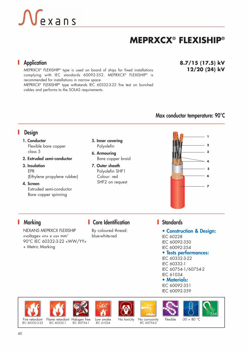
1.8/3 (3.6) kVMPRXCX® type is used on board of ships for fixed installations complying withIEC standards 60092-352. Thanks to its flexibility and low bending force,MPRXCX® FLEXISHIP® is recommended to be used in narrow space.MPRXCX® type withstands IEC 60332-3-22 fire test on bunched cables andperforms to the SOLAS requirements.
By colour:black - brown - grey
1. ConductorStranded bare copperclass 2 or Flexible barecopper class 5
2. InsulationXLPE(cross linked polyethylene)
1
2
4
3
5
Flame retardantIEC 60332--1
32
Exe17_NEXANS_catal_MARINE_avril2013 14/05/13 18:58 Page32

Products on request
1 x 25 127 15.0 15.9 17.5 5001 x 35 157 16.0 16.9 18.5 6201 x 50 196 17.5 18.1 19.5 7801 x 70 242 19.0 19.7 21.5 1 0001 x 95 293 21.0 21.8 23.5 1 2801 x 120 339 22.0 23.2 25.0 1 5401 x 150 389 24.0 24.8 26.5 1 8601 x 185 444 25.5 26.7 28.5 2 2301 x 240 522 28.5 29.8 32.0 2 8301 x 300 601 30.5 31.8 34.0 3 420
3 x 25 89 28.0 29.0 31.0 1 6103 x 35 110 30.0 31.2 33.5 2 0103 x 50 137 33.0 34.0 36.5 2 5903 x 70 169 36.5 37.7 40.5 3 3503 x 95 205 40.5 42.2 45.0 4 4003 x 120 237 44.0 45.8 49.0 5 3603 x 150 273 47.5 49.0 52.0 6 420
Cables (mm2)
Permissible currentrating in open air
(A)
Outer diameter
Min.(mm)
Nom.(mm)
Max.(mm)
Weightapprox.(kg/km)
MPRXCX® - 1.8/3 (3.6) kV
Products on request
1 x 25 127 15.5 16.4 18.0 5201 x 35 157 17.0 17.8 19.5 6501 x 50 196 18.0 19.0 20.5 8101 x 70 242 20.0 20.7 22.5 1 0301 x 95 293 22.0 23.2 25.0 1 3401 x 120 339 23.5 24.5 26.5 1 5901 x 150 389 26.0 27.0 29.0 1 9501 x 185 444 27.5 28.8 31.0 2 3201 x 240 522 31.5 32.8 35.0 2 9601 x 300 601 32.5 34.0 36.5 3 530
3 x 25 89 29.0 30.0 32.0 1 6903 x 35 110 32.5 33.6 36.0 2 1803 x 50 137 34.5 36.0 38.5 2 7303 x 70 169 38.5 39.9 42.5 3 5303 x 95 205 44.0 45.6 48.5 4 6603 x 120 237 47.0 48.6 52.0 5 5703 x 150 273 51.0 52.9 56.5 6 790
Cables (mm2)
Permissible currentrating in open air
(A)
Outer diameter
Min.(mm)
Nom.(mm)
Max.(mm)
Weightapprox.(kg/km)
MPRXCX® FLEXISHIP® - 1.8/3 (3.6) kV
Test Voltage 6.5 kV AC between cores
Minimum bending radiusFixed installations 6 x outer diameter
33
r
Cop
yrig
ht ©
Apr
il 20
13 -
Nex
ans
MED
IUM
VO
LTA
GE
CA
BLES
Exe17_NEXANS_catal_MARINE_avril2013 14/05/13 18:58 Page33

34
Core Identification
MPRXCX®
Design
Marking
5. Inner coveringPolyolefin
6. ArmouringBare copper braid
7. Outer sheathPolyolefin SHF1Colour: redSHF2 on request
Application
Standards
3.6/6 (7.2) kV6/10 (12) kVMPRXCX® Medium Voltage cable type is used on board of ships for fixed
installations complying with IEC standards 60092-352. Semi conductive layerover insulation is easily stripable.MPRXCX® type withstands IEC 60332-3-22 fire test on bunched cables andperforms to the SOLAS requirements.
1. ConductorStranded bare copperclass 2
2. Extruded semi-conductor
3. InsulationXLPE(cross linked polyethylene)
4. ScreenExtruded semi-conductorBare copper tape
1
2
3
7
Max conductor temperature: 90°C
NEXANS MPRXCX«voltage» «n» x «s» mm2
90°C IEC 60332-3-22«WW/YY»+ Metric Marking
• Construction & Design:IEC 60228IEC 60092-350IEC 60092-354• Tests performances:IEC 60332-3-22IEC 60332-1IEC 60754-1/60754-2IEC 61034• Materials:IEC 60092-351IEC 60092-359
By coloured thread: blue-white-red
-30 + 80 °CNo corrosivityIEC 60754-2
No toxicityFire retardantIEC 60332-3-22
Flame retardantIEC 60332-1
6
5
4
EMI
ClBrF
ClClClClClClClClClClClBrBrBrBrBrBrBrFFFFFFF
Low smokeIEC 61034
Halogen freeIEC 60754-1
Exe17_NEXANS_catal_MARINE_avril2013 14/05/13 18:58 Page34

35
MPRXCX® 3.6/6 (7.2) kV
Products on request
Products on request
1 x 25 127 22.0 22.8 24.5 8201 x 35 157 23.0 24.0 26.0 9601 x 50 196 24.0 24.9 26.5 1 1201 x 70 242 26.0 27.2 29.0 1 4101 x 95 293 27.5 28.9 31.0 1 7001 x 120 339 29.5 30.8 33.0 2 0001 x 150 389 30.5 31.9 34.0 2 3201 x 185 444 33.0 34.2 36.5 2 7501 x 240 522 35.5 37.1 39.5 3 3701 x 300 601 38.0 39.5 42.0 4 090
3 x 25 89 43.0 44.7 47.5 3 1203 x 35 110 45.5 47.1 50.5 3 6103 x 50 137 47.5 49.2 52.5 4 2103 x 70 169 51.5 53.3 56.5 5 1603 x 95 205 55.5 57.5 61.0 6 2903 x 120 237 59.5 61.4 65.0 7 3903 x 150 273 62.5 64.8 68.0 8 520
Cables (mm2)
Permissible currentrating in open air
(A)
Outer diameter
Min.(mm)
Nom.(mm)
Max.(mm)
Weightapprox.(kg/km)
MPRXCX® 6/10 (12) kV
1 x 25 127 19.0 20.0 21.5 7501 x 35 157 20.5 21.5 23.0 9001 x 50 196 21.5 22.5 24.0 1 0801 x 70 242 23.5 24.3 26.0 1 3301 x 95 293 25.0 26.0 28.0 1 6301 x 120 339 27.0 28.5 30.5 1 9501 x 150 389 28.5 30.0 32.0 2 300
3 x 25 89 38.0 39.5 42.5 2 7003 x 35 110 40.5 42.0 45.0 3 1603 x 50 137 42.5 44.5 47.0 3 8003 x 70 169 46.5 48.0 51.5 4 7503 x 95 205 50.5 52.5 56.0 5 8503 x 120 237 54.5 56.5 60.0 6 9503 x 150 273 58.0 60.0 63.5 8 100
Cables (mm2)
Permissible currentrating in open air
(A)
Outer diameter
Min.(mm)
Nom.(mm)
Max.(mm)
Weightapprox.(kg/km)
Test Voltage between conductor and screen in A.C. • 3.6/6 (7.2) kV Rated cables 12.5 kV• 6/10 (12) kV Rated cables 21 kV
Minimum bending radius for fixed installations• Single core cable 12 x outer diameter• 3 cores cable 9 x outer diameter
r
Cop
yrig
ht ©
Apr
il 20
13 -
Nex
ans
MED
IUM
VO
LTA
GE
CA
BLES
Exe17_NEXANS_catal_MARINE_avril2013 14/05/13 18:58 Page35

36
Core Identification
MEPRXCX®
Design
Marking
5. Inner coveringPolyolefin (only for 3 cores)
6. ArmouringBare copper braid
7. Outer sheathPolyolefin SHF1Colour: redSHF2 on request
NEXANS MEPRXCX«voltage» «n» x «s» mm2
90°C IEC 60332-3-22«WW/YY»+ Metric Marking
Application
Standards• Construction & Design:IEC 60228IEC 60092-350IEC 60092-354• Tests performances:IEC 60332-3-22IEC 60332-1IEC 60754-1/60754-2IEC 61034• Materials:IEC 60092-351IEC 60092-359
8.7/15 (17.5) kV12/20 (24) kVMEPRXCX® Medium Voltage cable type is used on board of ships for fixed
installations complying with IEC standards 60092-352. Semi conductive layerover insulation is easily stripable.MEPRXCX® type withstands IEC 60332-3-22 fire test on bunched cables andperforms to the SOLAS requirements.
By coloured thread: blue-white-red
1 ConductorStranded bare copperclass 2
2. Extruded semi-conductor
3. InsulationEPR(ethylene propylene rubber)
4. ScreenExtruded semi-conductorBare copper tape
Max conductor temperature: 90°C
1
2
4
7
3
6
5
-30 + 80 °CNo corrosivityIEC 60754-2
No toxicityLow smokeIEC 61034
Halogen freeIEC 60754-1
Fire retardantIEC 60332-3-22
Flame retardantIEC 60332-1
ClBrF
ClClClClClClClClClClBrBrBrBrBrBrBrFFFFFFF EMI
Exe17_NEXANS_catal_MARINE_avril2013 14/05/13 18:58 Page36

37
Cop
yrig
ht ©
Apr
il 20
13 -
Nex
ans
MED
IUM
VO
LTA
GE
CA
BLES
Products on request
1 x 25 127 25.0 26.0 28.0 1 0301 x 35 157 27.0 28.3 30.5 1 1801 x 50 196 28.0 29.3 31.5 1 3801 x 70 242 31.0 32.0 34.5 1 6401 x 95 293 33.0 34.0 36.5 1 9701 x 120 339 34.5 36.0 38.5 2 3101 x 150 389 36.5 38.0 40.5 2 6701 x 185 444 38.5 40.2 43.0 3 1501 x 240 522 41.5 43.2 46.0 3 8401 x 300 601 44.5 46.2 49.0 4 490
3 x 25 89 50.5 52.3 55.5 3 9003 x 35 110 52.5 54.6 58.0 4 4403 x 50 137 56.5 58.6 62.0 5 1103 x 70 169 62.0 64.5 68.5 6 1803 x 95 205 65.5 67.5 71.5 7 3303 x 120 237 70.0 72.3 76.5 8 5103 x 150 273 74.0 76.5 81.0 9 750
Cables (mm2)
Permissible currentrating in open air
(A)
Outer diameter
Min.(mm)
Nom.(mm)
Max.(mm)
Weightapprox.(kg/km)
MEPRXCX® - 8.7/15 (17.5) kV
Products on request
1 x 35 157 27.5 29.0 31.0 1 3901 x 50 196 28.5 30.0 32.0 1 5301 x 70 242 30.5 31.5 34.0 1 8101 x 95 293 32.5 34.0 36.0 2 1601 x 120 339 34.0 35.5 38.0 2 5001 x 150 389 35.5 37.0 39.5 2 9401 x 185 444 37.5 39.0 42.0 3 3401 x 240 522 40.5 42.0 45.0 4 0101 x 300 601 42.5 44.5 47.0 4 720
3 x 35 110 55.0 57.0 60.5 5 4003 x 50 137 57.5 59.5 63.0 6 1103 x 70 169 61.0 63.0 67.0 7 1403 x 95 205 65.0 67.5 71.0 8 4403 x 120 237 68.5 71.5 75.0 9. 6603 x 150 273 72.0 74.1 79.0 10 940
Cables (mm2)
Permissible currentrating in open air
(A)
Outer diameter
Min.(mm)
Nom.(mm)
Max.(mm)
Weightapprox.(kg/km)
MEPRXCX® - 12/20 (24) kV
Test Voltage between conductor and screen in A.C. 8.7/15 (17.5) kV Rated cables 30.5 kV12/20 (24) kV Rated cables 42 kV
Minimum bending radius for fixed installations• Single core cable 12 x outer diameter• 3 cores cable 9 x outer diameter
r
Exe17_NEXANS_catal_MARINE_avril2013 14/05/13 18:58 Page37

38
Core Identification
MPRXCX® FLEXISHIP®
Design
Marking
5. Inner coveringPolyolefin
6. ArmouringBare copper braid
7. Outer sheathPolyolefin SHF1Colour: redSHF2 on request
NEXANS MPRXCX FLEXISHIP«voltage» «n» x «s» mm2
90°C IEC 60332-3-22 «WW/YY»+ Metric Marking
Standards• Construction & Design:IEC 60228IEC 60092-350IEC 60092-354• Tests performances:IEC 60332-3-22IEC 60332-1IEC 60754-1/60754-2IEC 61034• Materials:IEC 60092-351IEC 60092-359
3.6/6 (7.2) kV6/10 (12) kVMPRXCX® FLEXISHIP® type is used on board of ships for fixed installations
complying with IEC standards 60092-352. MPRXCX® FLEXISHIP® isrecommended for installations in narrow space. MPRXCX® FLEXISHIP® type withstands IEC 60332-3-22 fire test on bunched cablesand performs to the SOLAS requirements.
By coloured thread:blue-white-red
1. ConductorFlexible bare copperclass 5
2. Extruded semi-conductor
3. InsulationXLPE or EPR(cross-linked polyethylene)
4. ScreenExtruded semi-conductorBare copper spinning
1
2
3
4
Application
Max conductor temperature: 90°C
ClBrF
ClClClClClClClClClClBrBrBrBrBrBrBrFFFFFFF EMI
-30 + 80 °CNo corrosivityIEC 60754-2
No toxicityLow smokeIEC 61034
Halogen freeIEC 60754-1
Fire retardantIEC 60332-3-22
Flame retardantIEC 60332-1
Flexible
5
6
7
Exe17_NEXANS_catal_MARINE_avril2013 14/05/13 18:59 Page38

39
Cop
yrig
ht ©
Apr
il 20
13 -
Nex
ans
MED
IUM
VO
LTA
GE
CA
BLES
MPRXCX® FLEXISHIP® 3.6/6 (7.2) kV
Products on request
1 x 25 127 19.5 20.3 22.0 7301 x 35 157 20.5 21.5 23.0 8701 x 50 196 21.5 22.7 24.5 1 0501 x 70 242 23.5 24.3 26.0 1 2801 x 95 293 25.0 26.2 28.0 1 5801 x 120 339 27.5 28.5 30.5 1 9101 x 150 389 28.5 29.9 32.0 2 2301 x 185 444 30.5 31.5 33.5 2 6201 x 240 522 33.5 35.0 37.5 3 2801 x 300 601 36.5 37.8 40.5 4 020
3 x 25 89 39.5 40.8 43.5 2 7803 x 35 110 41.5 42.9 46.0 3 2403 x 50 137 44.0 45.5 48.5 3 8703 x 70 169 48.0 49.5 52.5 4 8103 x 95 205 51.5 53.4 57.0 5 8703 x 120 237 56.0 57.8 61.0 7 0203 x 150 273 59.0 61.1 65.0 8 190
Cables (mm2)
Permissible currentrating in open air
(A)
Outer diameter
Min.(mm)
Nom.(mm)
Max.(mm)
Weightapprox.(kg/km)
MPRXCX® FLEXISHIP® 6/10 (12) kV
Products on request
1 x 25 127 22.0 23.2 25.0 8401 x 35 157 24.0 24.8 26.5 1 0101 x 50 196 25.0 26.2 28.0 1 2001 x 70 242 27.5 28.8 31.0 1 5001 x 95 293 30.0 31.1 33.5 1 7901 x 120 339 32.0 33.2 35.5 2 1401 x 150 389 34.0 35.3 38.0 2 5001 x 185 444 35.5 36.8 39.5 2 8501 x 240 522 39.0 40.4 43.0 3 5001 x 300 601 41.5 43.1 46.0 4 310
3 x 25 89 44.0 45.7 49.0 3 1403 x 35 110 47.0 48.9 52.0 3 7303 x 50 137 50.5 52.3 55.5 4 4703 x 70 169 55.5 57.2 61.0 5 5003 x 95 205 60.0 62.0 66.0 6 5803 x 120 237 64.0 66.0 70.0 7 7603 x 150 273 68.0 70.3 74.5 9 040
Cables (mm2)
Permissible currentrating in open air
(A)
Outer diameter
Min.(mm)
Nom.(mm)
Max.(mm)
Weightapprox.(kg/km)
Test Voltage between conductor and screen in A.C.• 3.6/6 (7.2) kV Rated cables 12.5 kV• 6/10 (12) kV Rated cables 21 kV
Minimum bending radius for fixed installations• Single core cable 9 x outer diameter• 3 cores cable 7.5 x outer diameter
r
Exe17_NEXANS_catal_MARINE_avril2013 14/05/13 18:59 Page39
40
Core Identification
MEPRXCX® FLEXISHIP®
Design
Marking
5. Inner coveringPolyolefin
6. ArmouringBare copper braid
7. Outer sheathPolyolefin SHF1Colour: redSHF2 on request
NEXANS MEPRXCX FLEXISHIP«voltage» «n» x «s» mm2
90°C IEC 60332-3-22 «WW/YY»+ Metric Marking
Standards• Construction & Design:IEC 60228IEC 60092-350IEC 60092-354• Tests performances:IEC 60332-3-22IEC 60332-1IEC 60754-1/60754-2IEC 61034• Materials:IEC 60092-351IEC 60092-359
8.7/15 (17.5) kV12/20 (24) kVMEPRXCX® FLEXISHIP® type is used on board of ships for fixed installations
complying with IEC standards 60092-352. MEPRXCX® FLEXISHIP® isrecommended for installations in narrow space. MEPRXCX® FLEXISHIP® type withstands IEC 60332-3-22 fire test on bunchedcables and performs to the SOLAS requirements.
By coloured thread:blue-white-red
1. ConductorFlexible bare copperclass 5
2. Extruded semi-conductor
3. InsulationEPR(Ethylene propylene rubber)
4. ScreenExtruded semi-conductorBare copper spinning
1
2
3
4
Application
Max conductor temperature: 90°C
EMI-30 + 80 °CNo corrosivity
IEC 60754-2No toxicityFire retardant
IEC 60332-3-22Flame retardant
IEC 60332-1Flexible
5
6
7
ClBrF
ClClClClClClClClClClBrBrBrBrBrBrBrFFFFFFF
Low smokeIEC 61034
Halogen freeIEC 60754-1
Exe17_NEXANS_catal_MARINE_avril2013 14/05/13 18:59 Page40

41
Cop
yrig
ht ©
Apr
il 20
13 -
Nex
ans
Test Voltage between conductor and screen in A.C.• 8.7/15 (17.5) kV Rated cables 30.5 kV• 12/20 (24) kV Rated cables 42 kVMinimum bending radius for fixed installations• Single core cable 9 x outer diameter• 3 cores cable 7.5 x outer diameter
r
MEPRXCX® FLEXISHIP® 8.7/15 (17.5) kV
1 x 25 127 25.0 26.0 28.0 1 0301 x 35 157 27.0 28.3 30.5 1 1801 x 50 196 28.0 29.3 31.5 1 3801 x 70 242 31.0 32.0 34.5 1 6401 x 95 293 33.0 34.0 36.5 1 9701 x 120 339 34.5 36.0 38.5 2 3101 x 150 389 36.5 38.0 40.5 2 6701 x 185 444 38.5 40.2 43.0 3 1501 x 240 522 41.5 43.2 46.0 3 8401 x 300 601 44.5 46.2 49.0 4 490
3 x 25 89 50.5 52.5 55.5 3 9003 x 35 110 52.5 54.6 58.0 4 4403 x 50 137 56.5 58.6 62.0 5 1103 x 70 169 62.0 64.5 68.5 6 1803 x 95 205 65.5 67.5 71.5 7 3303 x 120 237 70.0 72.3 76.5 8 5103 x 150 273 74.0 76.5 81.0 9 750
Cables (mm2)
Permissible currentrating in open air
(A)
Outer diameter
Min.(mm)
Nom.(mm)
Max.(mm)
Weightapprox.(kg/km)
MEPRXCX® FLEXISHIP® 12/20 (24) kV
1 x 35 157 29.0 30.3 32.5 1 3901 x 50 196 30.0 31.3 33.5 1 5301 x 70 242 33.0 34.5 37.0 1 8101 x 95 293 35.0 36.1 38.5 2 1601 x 120 339 36.5 37.9 40.5 2 5001 x 150 389 38.5 39.9 42.5 2 9401 x 185 444 44.0 45.6 48.5 3 3401 x 240 522 44.0 45.6 48.5 4 0101 x 300 601 46.5 48.2 51.0 4 720
3 x 35 110 57.5 59.3 63.0 5 4003 x 50 137 61.0 62.9 66.5 6 1103 x 70 169 66.5 68.7 73.0 7 1403 x 95 205 70.0 72.3 76.5 8 4403 x 120 237 74.0 76.6 81.0 9 6003 x 150 273 78.0 80.7 85.5 10 940
Cables (mm2)
Permissible currentrating in open air
(A)
Outer diameter
Min.(mm)
Nom.(mm)
Max.(mm)
Weightapprox.(kg/km)
MED
IUM
VO
LTA
GE
CA
BLES
Exe17_NEXANS_catal_MARINE_avril2013 14/05/13 18:59 Page41

Core Identification
MMGSHXCHX & MMGSEHXCHX
Design
Marking
5. Common covering(only for 3 cores)
6. Inner sheathCross linked polymere
7. ArmouringTinned copper braid
8. Outer sheathCross linked rubber SHF2Colour: red
NEXANS MMGSEHXCHX orMMGSHXCHX«n» x «s» / «Braid section» mm2
6/10 kV 90°C IEC 60092-354IEC 60332-3
«n»: number of cores«s»: cross section
Standards• Construction & Design :IEC 60092-354• Tests performances :IEC 60332-3-22IEC 60332-1IEC 60754-1/60754-2IEC 61034• Materials :IEC 60092-351IEC 60092-359
6/10 (12) kVFor fixed installations on ships and offshore-units. The cables meet the flametest requirements for bunched cables according to IEC 60332-3-22 and IEEE45-18.13 and perform to the SOLAS requirements.
Natural colour (beige)
1. ConductorFlexible tinned copperclass 5
2. Semi-conductorExtruded
3. InsulationEPR(Ethylene Propylene Rubber)
4. ScreenExtruded semi-conductorTinned copper wires
1
2
3
8
Application
Max conductor temperature: 90°C
4
5
6
7
EMI-30 + 75 °CNo corrosivity
IEC 60754-2No toxicityFire retardant
IEC 60332-3-22Flame retardant
IEC 60332-1Flexible
42
ClBrF
ClClClClClClClClClClBrBrBrBrBrBrBrFFFFFFF
Low smokeIEC 61034
Halogen freeIEC 60754-1
Exe17_NEXANS_catal_MARINE_avril2013 14/05/13 18:59 Page42

1 x 50/16 28.5 31.0 32.0 1 2301 x 70/16 30.0 32.0 33.0 1 5801 x 95/16 33.0 35.0 37.0 1 8901 x 120/16 34.0 36.0 38.0 2 2501 x 150/16 35.0 37.0 39.0 2 6001 x 185/25 36.0 38.0 40.0 2 9501 x 240/25 40.0 42.0 44.0 3 5501 x 300/25 43.0 45.0 47.0 4 100
MMGSHXCHX 6/10 (12) kV - Single core
Cables (mm2)
Outer diameter
Min.(mm)
Nom.(mm)
Max.(mm)
Weightapprox.(kg/km)
Products on request
3 x 25/16 48.0 50.0 52.0 3 4003 x 35/16 51.0 53.0 55.0 4 0503 x 50/16 55.0 57.0 59.0 4 7003 x 70/16 58.0 60.0 62.0 5 6503 x 95/16 64.0 66.0 68.0 6 9003 x 120/16 68.0 70.0 72.0 8 000
Cables (mm2)
Outer diameter
Min.(mm)
Nom.(mm)
Max.(mm)
Weightapprox.(kg/km)
MMGSEHXCHX 6/10 (12) kV - 3 cores
Products on request
Test Voltage between conductor and screen in A.C.• 3.6/6 (7.2) kV Rated cables 12.5 kV• 6/10 (12) kV Rated cables 21 kV
Minimum bending radius for fixed installations6 x outer diameter
r
43
Cop
yrig
ht ©
Apr
il 20
13 -
Nex
ans
MED
IUM
VO
LTA
GE
CA
BLES
Exe17_NEXANS_catal_MARINE_avril2013 14/05/13 18:59 Page43

Core Identification
MMGSHX & MMGSEHX
Design
Marking
4. ScreenExtruded semi-conductorTinned copper wires
5. Inner covering(only for 3 cores)
6. Outer sheathCross linked rubber SHF2Colour: red
NEXANS MMGSEHX orMMGSHX«n» x «s» voltage 85°CIEC 60092-354IEC 60332-3-22
«n»: number of cores«s»: cross section
Standards• Construction & Design :IEC 60092-354IEC 60502• Tests performances :IEC 60332-3-22IEC 60332-1IEC 60754-1/60754-2IEC 61034• Materials :IEC 60092-351IEC 60092-359
6/10 (12) kV8.7/15 (17.5) kVFor fixed installations on ships and offshore-units. The cables meet the flame
test requirements for bunched cables according to IEC 60332-3-22.
Natural colour (beige)
1. ConductorFlexible tinned copperclass 5
2. Semi-conductorExtruded
3. InsulationEPR(Ethylene Propylene Rubber)
1
2
3
4
Application
Max conductor temperature: 90°C
5
6
44
EMI-30 + 75 °CNo corrosivity
IEC 60754-2No toxicityFire retardant
IEC 60332-3-22Flame retardant
IEC 60332-1Flexible
ClBrF
ClClClClClClClClClClBrBrBrBrBrBrBrFFFFFFF
Low smokeIEC 61034
Halogen freeIEC 60754-1
Exe17_NEXANS_catal_MARINE_avril2013 14/05/13 18:59 Page44

1 x 70/16 24.0 25.5 27.0 1 3001 x 95/16 26.0 27.5 29.0 1 6001 x 120/16 28.0 29.5 31.0 1 8001 x 150/16 29.0 30.5 32.0 2 4001 x 185/25 31.5 33.0 34.5 2 8001 x 240/25 34.0 35.5 37.0 3 3001 x 300/25 36.5 38.0 39.5 3 700
Cables (mm2)
Outer diameter
Min.(mm)
Nom.(mm)
Max.(mm)
Weightapprox.(kg/km)
MMGSHX 6/10 (12) kV - Single core
Products on request
3 x 35/16 46.0 48.0 49.5 3 7003 x 50/16 48.5 50.0 52.0 4 2503 x 70/16 53.0 54.5 56.5 5 5003 x 95/16 57.0 58.0 61.0 7 3003 x 120/25 61.0 62.5 64.5 8 400
Cables (mm2)
Outer diameter
Min.(mm)
Nom.(mm)
Max.(mm)
Weightapprox.(kg/km)
MMGSEHX 6/10 (12) kV - 3 cores
Products on request
45
Cop
yrig
ht ©
Apr
il 20
13 -
Nex
ans
MED
IUM
VO
LTA
GE
CA
BLES
Exe17_NEXANS_catal_MARINE_avril2013 14/05/13 18:59 Page45

3 x 35/16 50.0 52.0 53.5 3 7003 x 50/16 54.0 56.0 57.5 4 2503 x 70/16 58.0 60.0 61.5 5 5003 x 95/16 63.0 65.0 66.5 7 3003 x 120/25 66.0 68.0 69.5 8 4003 x 150/25 71.0 73.0 74.5 9 4003 x 185/25 75.0 77.0 78.5 10 6003 x 240/25 81.5 83.5 85.0 12 100
1 x 120/16 32.5 31.0 29.5 1 9001 x 150/25 34.5 33.0 31.5 2 6001 x 185/25 36.0 34.5 33.0 3 0001 x 240/25 38.5 37.0 35.5 3 5001 x 300/25 41.5 40.0 38.5 3 900
Cables (mm2)
Outer diameter
Min.(mm)
Nom.(mm)
Max.(mm)
Weightapprox.(kg/km)
MMGSHX 8.7/15 (17.5) kV - Single core
Products on request
Cables (mm2)
Outer diameter
Min.(mm)
Nom.(mm)
Max.(mm)
Weightapprox.(kg/km)
MMGSEHX 8.7/15 (17.5) kV - 3 cores
Products on request
Test Voltage between conductor and screen in A.C.• 6/10 (12) kV Rated cables 21 kV• 8.7/15 (17.5) kV Rated cables 30.5 kV
Minimum bending radius for fixed installations• Single core cable 12 x outer diameter• 3 cores cable 6 x outer diameter
r
46
Exe17_NEXANS_catal_MARINE_avril2013 14/05/13 18:59 Page46

Test Voltage between conductor and screen in A.C.• 6/10 (12) kV Rated cables 21 kV• 8.7/15 (17.5) kV Rated cables 30.5 kV
Minimum bending radius for fixed installations• Single core cable 12 x outer diameter• 3 cores cable 6 x outer diameter
47
Cop
yrig
ht ©
Apr
il 20
13 -
Nex
ans
MED
IUM
VO
LTA
GE
CA
BLES
Exe17_NEXANS_catal_MARINE_avril2013 14/05/13 18:59 Page47

48
E.T.I.
Design10. Holding tape
Field-controlling copper wirebinding (2 mm2)
11. ArmouringBare copper braid
12. Cable outersheathPolyolefinColour: black
13. Shrinkable insulating sheathAnti tracking sheath
14. Braid connection to earth
Application 6/10 (12) kV 8.7/15 (17.5) kV
12/20 (24) kVTerminations are designed to connect Medium Voltage cables to equipmentssuch as transformers, alternators, motors... .
1 Cable lug
2. Filler tape
3. ConductorStranded bare copperClass 2 - IEC 60228
4. Heat-shrinkable tubingAnti tracking sheath
5. Heat-shrinkable tubing R.L.TStress Control Tubing
6. Semi-conductor tape
7. ScreenCopper tape: thickness = 0.2 mm
8. Holding tapeField-controlling copper wirebinding (2 mm2)
9. Heat-shrinkable trifurcating
1
23
4
5
6
12
1110
9
8
7
13
14
Exe17_NEXANS_catal_MARINE_avril2013 14/05/13 18:59 Page48

49
ETI - 10 - 16/120 6/10 (12) kV 16 - 120
ETI - 15 - 50/240 8.7/15 (17.5) kV 50 - 240
ETI - 20 - 50/150 12/20 (24) kV 50 - 150
VoltageDesignation Cross-section (mm2)
E.T.I. - Inner three-phase terminal
E3UI 12 - 120 6/10 (12) kV 120
ITK 224 MT 8.7/15 (17.5) kV 35 - 240
ITK 224 MT 12/20 (24) kV 50 - 150
VoltageDesignation Cross-section (mm2)
E.T.I. - Inner single-phase terminal
For any further details, please refer to the corresponding installation instructions.
Cop
yrig
ht ©
Apr
il 20
13 -
Nex
ans
MED
IUM
VO
LTA
GE
CA
BLES
Exe17_NEXANS_catal_MARINE_avril2013 14/05/13 18:59 Page49

Exe17_NEXANS_catal_MARINE_avril2013 14/05/13 18:59 Page50

Part 3Power & control1kV cables
51
Cop
yrig
ht ©
Apr
il 20
13 -
Nex
ans
POW
ER &
CO
NTR
OL
1KV
CA
BLES
Exe17_NEXANS_catal_MARINE_avril2013 14/05/13 18:59 Page51

Core Identification
Design
Marking
3. Outer sheath(Filler if necessary)Polyolefin SHF1Colour: blackSHF2 on request
NEXANS MPRX 0.6/1 kV «n» x «s» mm2
90°C IEC 60332-3-22 «WW/YY» * *
+ metric marking
Standards• Construction & Design :IEC 60228IEC 60092-350IEC 60092-353• Tests performancesIEC 60332-3-22IEC 60332-1IEC 60754-1/60754-2IEC 61034• MaterialsIEC 60092-351IEC 60092-359
0.6/1 (1.2) kVMPRX® type is used on board of ships for fixed installations, not subject tomechanical risk complying with IEC standards 60092-352. MPRX® typewithstands IEC 60332-3-22 fire test on bunched cables and performs to theSOLAS requirements.
1 core: black2 cores: brown-blue3 x: brown-black-grey3 G: brown-blue-green/yellow4 x: brown-black-grey-blue4 G: brown-black-grey-green/yellow5 G: brown-black-grey-green/yellow-blue5 x: white with printed numbers > 5 coresn x : white with printed numbersn G : white with printed numbers +green/yellow earth core
1. ConductorStranded bare copperclass 2
2. InsulationXLPE(cross linked polyethylene)
1
2
3
Application
Max conductor temperature: 90°C
ClBrF
ClClClClClClClClClClBrBrBrBrBrBrBrFFFFFFF
-30 + 80 °CNo corrosivityIEC 60754-2
No toxicityLow smokeIEC 61034
Halogen freeIEC 60754-1
Fire retardantIEC 60332-3-22
Flame retardantIEC 60332--1
MPRX®
Control & Power
52
Exe17_NEXANS_catal_MARINE_avril2013 14/05/13 18:59 Page52
1 x 1.5 23 4.6 4.9 5.6 401 x 2.5 30 5.0 5.4 6.2 501 x 4 40 5.5 6.0 6.8 601 x 6 52 5.8 6.3 7.2 801 x 10 72 6.6 7.1 8.0 1301 x 16 96 7.6 8.2 9.2 1801 x 25 127 9.6 10.1 11.5 2801 x 35 157 10.5 11.1 12.5 3801 x 50 196 11.5 12.4 13.5 4901 x 70 242 13.5 14.5 16.0 7001 x 95 293 15.5 16.2 17.5 9401 x 120 339 17.0 18.0 19.5 1 1801 x 150 389 19.0 20.0 21.5 1 4801 x 185 444 21.0 22.1 24.0 1 8101 x 240 522 24.0 25.0 27.0 2 3601 x 300 601 26.0 27.4 29.5 2 930
2 x 1.5 20 7.0 8.2 8.8 802 x 2.5 26 8.0 9.2 10.0 1002 x 4 34 9.6 10.4 11.5 1402 x 6 44 10.0 11.0 12.6 2002 x 10 61 12.0 12.8 14.9 3102 x 16 82 14.0 15.2 16.7 4602 x 25 108 17.5 18.8 20.5 700
3 x 1.5 / 3 G 1.5 16 7.5 8.7 9.2 1003 x 2.5 / 3 G 2.5 21 9.0 9.7 11.0 1403 x 4 28 10.0 11.0 12.0 1903 x 6 36 11.0 11.9 13.3 2603 x 10 50 12.5 13.6 15.8 3903 x 16 67 15.0 16.2 17.7 5803 x 25 89 19.0 20.0 21.5 9403x35 S19 110 18.8 20.1 21.3 1 1303x50 S37 137 21.0 22.3 23.5 1 5503x70 S52 169 24.4 25.7 26.9 2 1203x95 S61 205 28.6 29.9 31.1 3 0503x120 S61 237 31.3 32.6 33.8 3 700
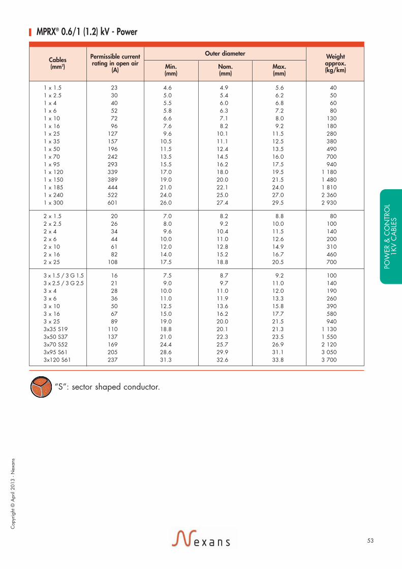
MPRX® 0.6/1 (1.2) kV - Power
Cables (mm2)
Permissible currentrating in open air
(A)
Outer diameter
Min.(mm)
Nom.(mm)
Max.(mm)
Weightapprox.(kg/km)
53
Cop
yrig
ht ©
Apr
il 20
13 -
Nex
ans
“S”: sector shaped conductor.PO
WER
& C
ON
TRO
L1K
V C
ABL
ES
Exe17_NEXANS_catal_MARINE_avril2013 14/05/13 18:59 Page53

Cables (mm2)
Permissible currentrating in open air
(A)
Outer diameter
Min.(mm)
Nom.(mm)
Max.(mm)
Weightapprox.(kg/km)
MPRX® 0.6/1 (1.2) kV - Power
4 x 1.5 / 4 G 1.5 16 8.8 9.2 10.5 1204 x 2.5 / 4 G 2.5 21 10.0 10.4 11.5 1704 x 4 / 4 G 4 28 11.5 11.9 13.5 2504 x 6 / 4 G 6 36 12.0 12.8 14.0 3304 x 10 / 4 G 10 50 14.0 14.9 16.5 5004 x 16 / 4 G 16 67 17.0 18.0 19.5 7704 x 25 / 4 G 25 89 21.0 22.3 24.0 1 1804 x 35 S 19 110 24.0 23.7 24.9 1 5004 x 50 S 37 137 25.1 26.4 27.6 2 100
5 x 1.5 / 5 G 1.5 16 9.6 10.5 11.5 1605 x 2.5 / 5 G 2.5 21 10.5 11.4 12.5 2005 G 4 28 12.5 13.2 14.5 3205 G 6 36 13.5 14.2 15.5 4205 G 10 50 15.5 16.4 18.0 630
7 x 1.5 11 10.5 11.4 12.5 20010 x 1.5 10 13.3 14.1 14.8 26012 x 1.5 10 14.0 15.3 16.5 33014 x 1.5 10 14.9 15.7 16.4 35016 x 1.5 9 15.7 16.5 17.2 40019 x 1.5 9 16.5 17.6 19.0 50024 x 1.5 8 19.5 20.7 22.5 63027 x 1.5 8 20.0 21.1 23.0 70037 x 1.5 7 23.0 24.6 26.0 930
7 x 2.5 16 12.0 12.8 14.0 28012 x 2.5 13 15.5 16.9 18.5 46019 x 2.5 11 18.5 20.0 21.5 69024 x 2.5 10 22.0 23.8 25.5 88027 x 2.5 10 23.0 24.5 26.5 97037 x 2.5 9 25.5 27.6 29.5 1 300
Cables (mm2)
Permissible currentrating in open air
(A)
Outer diameter
Min.(mm)
Nom.(mm)
Max.(mm)
Weightapprox.(kg/km)
MPRX® 0.6/1 (1.2) kV - Control
54
Test Voltage 3.5 kV AC between cores
Minimum bending radius for fixed installations• cable diameter ≤ 25 mm 4 x outer diameter• cable diameter > 25 mm 6 x outer diameter
r
MPRX® cables are also manufactured with extruded inner covering, on request
Exe17_NEXANS_catal_MARINE_avril2013 14/05/13 18:59 Page54

55
Cop
yrig
ht ©
Apr
il 20
13 -
Nex
ans
POW
ER &
CO
NTR
OL
1KV
CA
BLES
Exe17_NEXANS_catal_MARINE_avril2013 14/05/13 18:59 Page55
56
Core Identification
MPRXCX®
Control & Power
Design
Marking
4. ArmouringBare copper braid
5. Outer sheathPolyolefin SHF1Colour: blackSHF2 on request
NEXANS MPRXCX0.6/1 kV «n» x «s» mm2
90°C IEC 60332-3-22«WW/YY» * *+ Metric Marking
Standards• Construction & Design:IEC 60228IEC 60092-350IEC 60092-353 • Tests performances:IEC 60332-3-22IEC 60332-1IEC 60754-1/60754-2IEC 61034• Materials:IEC 60092-351IEC 60092-359
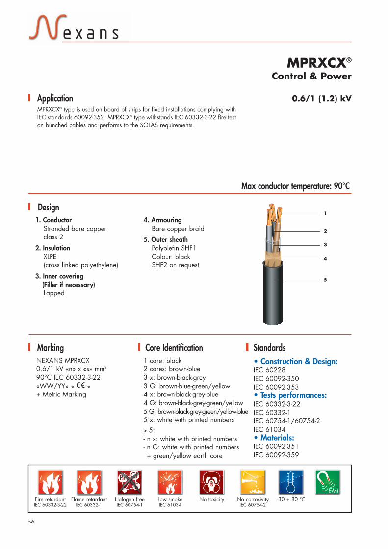
0.6/1 (1.2) kVMPRXCX® type is used on board of ships for fixed installations complying withIEC standards 60092-352. MPRXCX® type withstands IEC 60332-3-22 fire teston bunched cables and performs to the SOLAS requirements.
1 core: black2 cores: brown-blue3 x: brown-black-grey3 G: brown-blue-green/yellow4 x: brown-black-grey-blue4 G: brown-black-grey-green/yellow5 G: brown-black-grey-green/yellow-blue5 x: white with printed numbers > 5:- n x: white with printed numbers- n G: white with printed numbers+ green/yellow earth core
1. ConductorStranded bare copper class 2
2. InsulationXLPE(cross linked polyethylene)
3. Inner covering(Filler if necessary)Lapped
1
2
3
4
Application
Max conductor temperature: 90°C
ClBrF
ClClClClClClClClClClBrBrBrBrBrBrBrFFFFFFF EMI
-30 + 80 °CNo corrosivityIEC 60754-2
No toxicityLow smokeIEC 61034
Halogen freeIEC 60754-1
Fire retardantIEC 60332-3-22
5
Flame retardantIEC 60332-1
Exe17_NEXANS_catal_MARINE_avril2013 14/05/13 18:59 Page56

57
1 x 1.5 23 5.8 6.3 7.2 701 x 2.5 30 6.2 6.7 7.6 801 x 4 40 6.6 7.3 8.4 1001 x 6 52 7.0 7.6 8.2 1201 x 10 72 8.0 8.6 9.4 1801 x 16 96 9.0 9.7 10.5 2501 x 25 127 10.5 11.6 12.5 3601 x 35 157 11.5 12.6 13.5 4701 x 50 196 13.5 14.4 15.5 6601 x 70 242 15.5 16.5 17.5 8101 x 95 293 17.0 18.0 19.5 1 0601 x 120 339 19.0 19.8 21.5 1 3201 x 150 389 20.5 21.8 23.5 1 6301 x 185 444 22.5 23.9 25.5 1 9801 x 240 522 25.5 26.8 28.5 2 5501 x 300 601 28.0 29.2 31.5 3 140
2 x 1.5 20 8.3 9.5 10.5 1302 x 2.5 26 9.1 10.3 11.5 1602 x 4 34 10.3 11.7 13.0 2102 x 6 44 11.5 12.3 14.0 2802 x 10 61 13.5 14.6 17.0 4302 x 16 82 16.0 17.0 18.5 6002 x 25 108 19.0 20.6 22.5 880
3 x 1.5 / 3 G 1.5 16 8.8 10.0 11.0 1503 x 2.5/ 3 G 2.5 21 10.0 10.8 12.0 1903 x 4 28 11.0 12.3 13.5 2603 x 6 36 12.0 13.0 14.5 3303 x 10 50 14.0 15.3 17.0 5303 x 16 67 16.5 17.9 19.5 7703 x 25 89 20.5 21.8 23.5 1 1403 x 35 S19 110 20.5 22.0 23.5 1 3203 x 50 S37 137 24.0 25.6 27.0 1 6503 x 70 S52 169 27.0 29.0 30.5 2 3703 x 95 S61 205 31.0 33.0 34.5 3 2003 x 120 S61 237 34.0 35.5 37.5 4 050
Cables (mm2)
Permissible currentrating in open air
(A)
Outer diameter
Min.(mm)
Nom.(mm)
Max.(mm)
Weightapprox.(kg/km)
MPRXCX® 0.6/1 (1.2) kV - Power
Cop
yrig
ht ©
Apr
il 20
13 -
Nex
ans
“S”: sector shaped conductor.PO
WER
& C
ON
TRO
L1K
V C
ABL
ES
Exe17_NEXANS_catal_MARINE_avril2013 14/05/13 18:59 Page57

58
4 x 1.5 / 4 G 1.5 16 9.8 10.7 12.0 1804 x 2.5 / 4 G 2.5 21 11.0 11.9 13.0 2404 x 4 28 12.5 13.4 15.0 3204 x 6 36 13.5 14.7 16.0 4504 x 10 50 15.5 16.9 18.5 6404 x 16 67 18.5 19.7 21.5 9304 x 25 89 22.5 24.0 26.0 1 3804 x 35 S19 110 23.0 24.3 26.0 1 7004 x 50 S37 137 26.0 27.3 29.0 2 3004 x 70 S52 169 31.5 32.8 34.0 3 2204 x 95 S61 205 35.5 36.8 39.0 4 300
5 x 1.5 / 5 G 1.5 16 10.5 11.8 13.0 2305 x 2.5 / 5 G 2.5 21 12.0 12.9 14.5 2905 G 4 28 14.5 15.2 16.5 3605 G 6 36 15.0 15.8 17.5 4905 G 10 50 17.5 18.1 20.0 720
MPRXCX® 0.6/1 (1.2) kV - Control
7 x 1.5 12 11.5 12.7 14.0 27010 x 1.5 11 14.5 15.3 17.5 38012 x 1.5 10 15.5 17.0 18.0 46014 x 1.5 9 16.5 17.3 19.0 47016 x 1.5 9 17.5 18.5 20.0 53019 x 1.5 9 18.0 19.8 21.0 65024 x 1.5 8 21.0 23.0 24.5 76027 x 1.5 8 21.5 23.4 24.5 87037 x 1.5 7 24.0 26.2 27.5 1 060
7 x 2.5 16 13.5 14.6 16.0 39012 x 2.5 13 17.0 18.7 20.5 61019 x 2.5 11 20.0 21.8 23.5 87024 x 2.5 10 23.5 25.6 27.5 1 10027 x 2.5 10 24.0 26.1 28.0 1 20037 x 2.5 9 27.0 29.2 31.5 1 560
Cables (mm2)
Permissible currentrating in open air
(A)
Outer diameter
Min.(mm)
Nom.(mm)
Max.(mm)
Weightapprox.(kg/km)
Cables (mm2)
Permissible currentrating in open air
(A)
Outer diameter
Min.(mm)
Nom.(mm)
Max.(mm)
Weightapprox.(kg/km)
MPRXCX® 0.6/1 (1.2) kV Power
Test Voltage 3.5 kV AC between cores
Minimum bending radius for fixed installations6 x outer diameter
r
MPRXCX® cables are also manufactured with extruded inner covering, on request.
Exe17_NEXANS_catal_MARINE_avril2013 14/05/13 18:59 Page58

59
Cop
yrig
ht ©
Apr
il 20
13 -
Nex
ans
POW
ER &
CO
NTR
OL
1KV
CA
BLES
Exe17_NEXANS_catal_MARINE_avril2013 14/05/13 18:59 Page59

60
Core Identification
MPRX® FLEXISHIP®
Power
Design
Marking
3. Outer sheath (Filler if necessary)Polyolefin SHF1Colour: blackSHF2 on request
NEXANS MPRX FLEXISHIP0.6/1 kV «n» x «s» mm2
90°C IEC 60332-3-22«WW/YY» * *+ Metric Marking
Standards• Construction & Design:IEC 60228IEC 60092-350IEC 60092-353• Tests performances:IEC 60332-3-22IEC 60332-1IEC 60754-1/60754-2IEC 61034• Materials:IEC 60092-351IEC 60092-359
0.6/1 (1.2) kVMPRX® FLEXISHIP® type is used on board of ships for fixed installations, notsubject to mechanical risk, complying with IEC standards 60092-352. MPRX®
FLEXISHIP® is recommended for installations in narrow space, and in particularfor connexions. Bending force is reduced by 30% to compare with MPRX® cable.MPRX® FLEXISHIP® type withstands IEC 60332-3-22 fire test on bunched cablesand performs to the SOLAS requirements.
1 core: black2 cores: brown-blue3 x: brown-black-grey3 G: brown-blue-green/yellow4 x: brown-black-grey-blue4 G: brown-black-grey-green/yellow5 G: brown-black-grey-green/yellow-blue
1. ConductorFlexible bare copperclass 5 • sector-shaped for 3 coreswith cross section from 70 mm2
to 150 mm2
2. InsulationXLPE(cross linked polyethylene)
1
2
3
Application
Max conductor temperature: 90°C
ClBrF
ClClClClClClClClClClBrBrBrBrBrBrBrFFFFFFF
-30 + 80 °CNo corrosivityIEC 60754-2
No toxicityLow smokeIEC 61034
Halogen freeIEC 60754-1
Fire retardantIEC 60332-3-22
Flame retardantIEC 60332-1
Flexible
Exe17_NEXANS_catal_MARINE_avril2013 14/05/13 18:59 Page60

61
Cop
yrig
ht ©
Apr
il 20
13 -
Nex
ans
POW
ER &
CO
NTR
OL
1KV
CA
BLES
Cables (mm2)
Permissible currentrating in open air
(A)
Outer diameter
Min.(mm)
Nom.(mm)
Max.(mm)
Weightapprox.(kg/km)
MPRX® FLEXISHIP® 0.6/1 (1.2) kV - Power
“S”: sector shaped conductor.
Test Voltage 3.5 kV AC between cores
Minimum bending radius for fixed installations4 x outer diameter
r
1 x 35 157 11.0 11.5 12.5 4001 x 50 196 12.5 13.4 14.5 5601 x 70 242 15.0 15.5 17.0 7801 x 95 293 17.0 17.6 19.0 1 0301 x 120 339 18.5 19.3 21.0 1 2901 x 150 389 21.0 21.8 23.5 1 6001 x 185 444 22.5 23.5 25.5 1 7501 x 240 522 26.5 27.6 29.5 2 260
3 x 10 50 13.5 14.2 15.5 3503 x 16 67 17.0 17.6 19.0 5903 x 25 89 20.0 21.1 23.0 8903 x 35 110 22.5 23.2 25.0 1 2303 x 50 137 26.5 27.5 29.5 1 6903 x 70 S 169 26.5 27.7 30.0 2 2103 x 95 S 205 30.5 31.8 34.0 2 8703 x 120 S 237 33.5 35.0 37.5 3 6603 x 150 S 273 38.0 39.4 42.0 4 570
4 x 10 / 4 G 10 50 15.0 15.8 17.5 6004 x 16 / 4 G 16 67 18.5 19.5 21.5 9304 x 25 / 4 G 25 89 22.5 23.5 25.5 1 4104 x 35 / 4 G 35 110 25.0 26.1 28.0 1 8604 x 50 / 4 G 50 137 29.0 30.4 32.5 2 1804 x 70 / 4 G 70 169 33.5 34.9 37.5 3 200
Exe17_NEXANS_catal_MARINE_avril2013 14/05/13 18:59 Page61

62
Core Identification
MPRXCX® FLEXISHIP®
Power
Design
Marking
4. ArmouringBare copper braid
5. Outer sheathPolyolefin SHF1Colour: blackSHF2 on request
NEXANS MPRXCX FLEXISHIP0.6/1 kV «n» x «s» mm2
90°C IEC 60332-3-22 «WW/YY»* *+ Metric Marking
Standards• Construction & Design:IEC 60228IEC 60092-350IEC 60092-353• Tests performances:IEC 60332-3-22IEC 60332-1IEC 60754-1/60754-2IEC 61034• Materials:IEC 60092-351IEC 60092-359
0.6/1 (1.2) kVMPRXCX® FLEXISHIP® type is used on board of ships for fixed installationscomplying with IEC standards 60092-352.MPRXCX® FLEXISHIP® is recommended for installations in narrow space, inparticular for connexions. Bending force is reduced by 30% compared toMPRXCX® cable. MPRXCX® FLEXISHIP® type withstands IEC 60332-3-22 firetest on bunched cables and performs to the SOLAS requirements.
1 core: black2 cores: brown-blue3 x: brown-black-grey3 G: brown-blue-green/yellow4 x: brown-black-grey-blue4 G: brown-black-grey-green/yellow5 G: brown-black-grey-green/yellow-blue
1. ConductorFlexible bare copperclass 5• sector-shaped for 3 coreswith cross section from 70 mm2
to 150 mm2
2. InsulationXLPE(cross linked polyethylene)
3. Inner covering(Filler if necessary)Lapped
1
2
3
4
Application
ClBrF
ClClClClClClClClClClClBrBrBrBrBrBrBrFFFFFFF
-30 + 80 °CNo corrosivityIEC 60754-2
No toxicityLow smokeIEC 61034
Halogen freeIEC 60754-1
Fire retardantIEC 60332-3-22
Flame retardantIEC 60332-1
Flexible
Max conductor temperature: 90°C
5
EMI
Exe17_NEXANS_catal_MARINE_avril2013 14/05/13 18:59 Page62

63
1 x 35 157 12.5 13.0 14.5 4801 x 50 196 14.5 15.4 17.0 6801 x 70 242 16.5 17.5 19.0 8701 x 95 293 18.5 19.2 21.0 1 0901 x 120 339 20.5 21.3 23.0 1 3401 x 150 389 23.0 23.8 25.5 1 6601 x 185 444 24.0 25.5 27.5 1 9901 x 240 522 28.5 29.6 31.5 2 520
3 x 10 50 15.5 16.0 17.5 5303 x 16 67 18.5 19.3 21.0 7803 x 25 89 22.0 22.8 24.5 1 1303 x 35 110 24.0 25.0 27.0 1 4703 x 50 137 28.0 29.0 31.0 2 0103 x 70 S 169 27.5 29.3 31.5 2 3403 x 95 S 205 31.5 33.3 36.0 3 0103 x 120 S 237 35.0 37.0 39.5 3 8703 x 150 S 273 39.5 41.4 44.5 4 800
4 x 10 / 4 G 10 50 17.0 17.6 19.0 6404 x 16 / 4 G 16 67 20.5 21.3 23.0 9704 x 25 / 4 G 25 89 24.0 25.2 27.0 1 4204 x 35 / 4 G 35 110 26.5 27.6 29.5 1 8204 x 50 / 4 G 50 137 31.0 32.1 34.5 2 3204 x 70 / 4 G 70 169 37.5 39.1 42.0 3 320
MPRXCX® FLEXISHIP® 0.6/1 (1.2) kV - Power
Cables (mm2)
Permissible currentrating in open air
(A)
Outer diameter
Min.(mm)
Nom.(mm)
Max.(mm)
Weightapprox.(kg/km)
Test Voltage 3.5 kV AC between cores
Minimum bending radius for fixed installations5 x outer diameter
r
Cop
yrig
ht ©
Apr
il 20
13 -
Nex
ans
MPRXCX® cables are also manufactured with extruded inner covering, on request.
“S”: sector shaped conductor.
POW
ER &
CO
NTR
OL
1KV
CA
BLES
Exe17_NEXANS_catal_MARINE_avril2013 14/05/13 18:59 Page63

64
Core Identification
MPRX®(ST)X
Design
MarkingNEXANS MPRX(ST)X "n" x "s"mm2
0,6 / 1 kV 90° IEC 60332-3-22 Cat. Year * *
Cores with green/yellow3 Green/yellow/blue/brown4 Green/yellow/brown/black/brown5 Green/yellow/brown/black/greyUp to 7 Green/yellow/white (with black numbers)
Cores without green/yellow 2 Blue/brown3 Brown/black/grey4 Blue/brown/black/grey 5 White cores (with black numbers) Up to 7 White cores (with black numbers)
Application 0.6/1 kVFor fixed installation on ship and offshore-units. The cables meet the flame testrequirements for bunched cables acc. to IEC 60332-3-22.All cable materials are free of halogens. This design ensures that non corrosiveand low toxic gases are emitted in case of fire. Therefore, these cables areespecially suitable for the installation on Mega Yachts.
Max conductor temperature: 90°C
1. ConductorPlain copper conductorAcc. To IEC 60228, class 2 (RM)
2. InsulationXLPE acc. To IEC 60092-351(cross linked polyethylene)
3. Inner coveringPolyester tape and PP-tape
4. Collective screenAlu/Polyester tape with drain wire
5. SeparatorPolyester tape (optional)
6. Outer sheathPolyolefin type SHF1Acc. To IEC 60092-359 black
ClBrF
ClClClClClClClClClClBrBrBrBrBrBrBrFFFFFFF
-30 + 80 °CFire retardantIEC 60332-3-22
Flame retardantIEC 60332-1
No corrosivityIEC 60754-2
No toxicityLow smokeIEC 61034
Halogen freeIEC 60754-1
MPRX(ST)XXLPE insulated, electrostatic screening and polyolefin halogenfree outer sheath acc. To IEC 60092-353
1
2
4
6
Exe17_NEXANS_catal_MARINE_avril2013 14/05/13 18:59 Page64

65
2 core cables2 x 1.5 7.0 9.5 802 x 2.5 8.0 10.5 105
3 core cables3 x 1.5 8.0 10.5 1003 x 2.5 9.0 11.5 140
4 core cables4 x 1.5 8.5 11.0 1304 x 2.5 10.0 12.5 180
Multicore cables
5 x 1.5 9.5 12.0 1657 x 1.5 10.5 13.0 205
10 x 1.5 13.5 16.0 29012 x 1.5 14.0 17.0 33014 x 1.5 14.9 16.4 36019 x 1.5 16.5 19.5 50024 x 1.5 19.5 21.0 60027 x 1.5 20.0 23.0 7005 x 2.5 10.5 13.0 2257 x 2.5 12.0 14.0 280
10 x 2.5 14.5 16.0 42012 x 2.5 15.5 16.9 48019 x 2.5 18.5 21.5 70027 x 2.5 23.0 26.5 980
Cables (mm2)
Outer diameter
Min.(mm)
Max.(mm)
Weightapprox.(kg/km)
MPRX®(ST)X 0.6/1 kV
Further technical details Rated voltage (AC or DC): U /U= 0,6/1 kV 4 Green/yellow/brown/black/brownMax. voltage in DC-systems: 1,8 kV conductor/conductor or 0,9 kV conductor/earth
Max. rated conductor temperature: normal operation : 85 °C / short circuit: 250 °CLowest installation temperature: 10°CLowest temperature for fixed installation: -35°CMinimum internal bending radius:
• For overall diameter of cable <25 mm: 4 x overall cable diameter• For overall diameter of cable >25 mm: 6 x overall cable diameter
Current rating for continuous operation: See IEC 60092-352Further hinds for cable installation: See IEC 60092-352
Cop
yrig
ht ©
Apr
il 20
13 -
Nex
ans
POW
ER &
CO
NTR
OL
1KV
CA
BLES
Exe17_NEXANS_catal_MARINE_avril2013 14/05/13 18:59 Page65

Fire resistantIEC 60331-21
IEC 60331-1 or 2
66
Core Identification
MPRX® 331Control & Power
Design
MarkingNEXANS MPRX 3310.6/1kV «n» x «s» mm2
90°C IEC 60332-3-22«WW/YY»* *+ Metric Marking
Standards• Construction & Design:IEC 60228IEC 60092-350IEC 60092-353• Tests performances:IEC 60331-21IEC 60331-1 or 2IEC 60332-1IEC 60332-3-22IEC 60754-1/60754-2IEC 61034• Materials:IEC 60092-351IEC 60092-359
1 core: black2 cores: brown-blue3 x: brown-black-grey3 G: brown-blue-green/yellow4 x: brown-black-grey-blue4 G: brown-black-grey-green/yellow5 G: brown-black-grey-green/yellow-blue5 x: white with printed numbers ≥ 5:- n x: white with printed numbers- n G: white with printed numbers + green/yellow earth core
1
2
3
Application 0.6/1 (1.2) kVMPRX® 331 type is used on board of ships for fixed installations, not subject tomechanical risk complying with IEC standards 60092-352 in safety circuits,where fire resistance is required.MPRX®331 type meets the IEC 60331-21 and also IEC 60331-1 or 2fire resistant performances during 90 minutes, withstands IEC 60332-3-22 firetest on bunched cables and performs to the SOLAS requirements.
Max conductor temperature: 90°C
1. ConductorStranded bare copperclass 2
2. Insulation• Cross section 1.5 - 2.5 - 4 mm2:Special Fire Resistant HF 90Halogen Free Compound
• Cross section ≥ 6mm2 :silicone rubber S95
3. Outer Sheath(Filler if necessary) Polyolefin SHF1Colour: orangeSHF2 on request
ClBrF
ClClClClClClClClClClBrBrBrBrBrBrBrFFFFFFF
-30 + 80 °CFire retardantIEC 60332-3-22
Flame retardantIEC 60332-1
No corrosivityIEC 60754-2
No toxicityLow smokeIEC 61034
Halogen freeIEC 60754-1
Exe17_NEXANS_catal_MARINE_avril2013 14/05/13 18:59 Page66

67
1 x 25 127 10.0 10.4 12.5 3101 x 35 157 11.0 11.4 13.5 4101 x 50 196 12.0 12.8 15.0 5601 x 70 242 14.0 14.8 17.5 7801 x 95 293 16.5 17.5 19.5 1 0301 x 120 339 19.0 19.6 21.5 1 290
2 x 1.5 20 7.6 8.0 9.0 702 x 2.5 26 8.6 9.2 10.5 1002 x 4 34 9.6 10.4 11.5 1402 x 6 44 12.0 12.4 14.0 2702 x 10 61 13.5 14.0 15.5 3802 x 16 82 15.5 16.4 18.0 5602 x 25 108 19.0 20.0 21.5 8502 x 35 133 21.5 22.2 24.0 1 1102 x 50 167 24.5 25.4 27.5 1 520
3 x 1.5 16 8.2 8.5 9.4 1003 x 2.5 21 9.4 9.7 11.0 1403 x 4 28 10.5 11.0 12.5 2003 x 6 36 12.5 13.2 14.5 3303 x 10 50 14.5 15.1 16.5 4803 x 16 67 17.0 17.6 19.5 7303 x 25 89 20.5 21.5 23.5 1 1103 x 35 110 23.0 23.9 26.0 1 4603 x 50 137 26.0 27.1 29.0 2 000
4 x 1.5 16 9.0 9.4 10.5 1304 x 2.5 21 10.0 10.6 12.0 1804 x 4 28 11.5 12.3 13.5 2604 x 6 36 14.0 14.6 16.0 4204 x 10 50 16.0 16.6 18.0 6104 x 16 67 18.5 19.4 21.0 9304 x 25 89 23.0 23.9 26.0 1 4204 x 35 110 25.5 26.7 29.0 1 880
5 x 1.5 14 9.8 10.3 11.5 1707 x 1.5 12 10.5 11.1 12.5 210
12 x 1.5 10 14.0 14.9 16.5 35019 x 1.5 9 17.0 17.6 19.0 52027 x 1.5 8 20.0 21.1 23.0 73037 x 1.5 8 23.0 24.0 26.0 980
5 x 2.5 18 11.0 11.6 13.0 2307 x 2.5 16 12.0 12.8 14.0 300
12 x 2.5 13 16.0 16.8 18.5 49019 x 2.5 11 19.0 20.0 21.5 75027 x 2.5 10 23.5 24.5 26.5 1 060
Cables (mm2)
Permissible currentrating in open air
(A)
Outer diameter
Min.(mm)
Nom.(mm)
Max.(mm)
Weightapprox.(kg/km)
MPRX® 331 0.6/1 (1.2) kV - Control & Power
Test Voltage 3.5 kV AC between cores
Minimum bending radius for fixed installations• cable diameter ≤ 25 mm 4 x outer diameter• cable diameter > 25 mm 6 x outer diameter
r
Cop
yrig
ht ©
Apr
il 20
13 -
Nex
ans
POW
ER &
CO
NTR
OL
1KV
CA
BLES
Exe17_NEXANS_catal_MARINE_avril2013 14/05/13 18:59 Page67

68
Core Identification
MPRXCX® 331Control & Power
Design
Marking
3. Inner coveringExtruded
4. ArmouringBare copper braid
5. Outer sheathPolyolefin SHF1Colour: orangeSHF2 on request
NEXANS MPRXCX 3310.6/1 kV «n» x «s» mm2
90°C IEC 60332-3-22«WW/YY» * *+ Metric Marking
Standards• Construction & Design:IEC 60228IEC 60092-350IEC 60092-353• Tests performances:IEC 60331-21IEC 60331-1 or 2IEC 60332-1IEC 60332-3-22IEC 60754-1/60754-2IEC 61034• Materials:IEC 60092-351IEC 60092-359
1 core: black2 cores: brown-blue3 x: brown-black-grey3 G: brown-blue-green/yellow4 x: brown-black-grey-blue4 G: brown-black-grey-green/yellow5 G: brown-black-grey-green/yellow-blue ≥ 5 cores:- n x: white with printed numbers- n G: white with printed numbers+ green/yellow earth core
1. ConductorStranded bare copperclass 2
2. Insulation• Cross section 1.5 - 2.5 - 4 mm2:Special Fire Resistant HF 90Halogen Free Compound
• Cross section ≥ 6 mm2 :silicone rubber S95
12
3
4
Application 0.6/1 (1.2) kVMPRXCX® 331 type is used on board of ships for fixed installations complyingwith IEC standards 60092-352 in safety circuits, where fire resistance isrequired. MPRXCX® 331 type meets the IEC 60331-21 and also IEC 60331-1or 2 fire characteristics during 90 minutes, withstands IEC 60332-3-22 fire teston bunched cables and performs to the SOLAS requirements.
Max conductor temperature: 90°C
ClBrF
ClClClClClClClClClClBrBrBrBrBrBrBrFFFFFFF EMI
-30 + 80 °CNo corrosivityIEC 60754-2
No toxicityLow smokeIEC 61034
Halogen freeIEC 60754-1
Fire resistantIEC 60331-21
IEC 60331-1 or 2
Fire retardantIEC 60332-3-22
Flame retardantIEC 60332-1
5
Exe17_NEXANS_catal_MARINE_avril2013 14/05/13 18:59 Page68

69
Cables (mm2)
Permissible currentrating in open air
(A)
Outer diameter
Min.(mm)
Nom.(mm)
Max.(mm)
Weightapprox.(kg/km)
MPRXCX® 331 - 0.6/1 (1.2) kV - Control & Power
1 x 25 127 11.5 13.0 14.5 4101 x 35 157 12.5 14.6 16.0 5501 x 50 196 14.5 15.8 17.0 7201 x 70 242 16.5 17.8 19.5 9601 x 95 293 18.5 20.7 22.5 1 2501 x 120 339 20.5 22.8 24.5 1 540
2 x 1.5 20 10.0 10.5 12.0 1802 x 2.5 26 11.0 11.7 13.0 2302 x 4 34 12.5 12.9 14.5 2902 x 6 44 14.5 15.2 16.5 4002 x 10 61 15.0 16.6 18.0 5702 x 16 82 17.5 19.0 20.5 7702 x 25 108 21.0 22.8 24.5 1 1302 x 35 133 24.0 25.0 27.0 1 4202 x 50 167 26.5 28.0 30.0 1 860
3 x 1.5 16 10.5 11.2 12.5 2103 x 2.5 21 11.5 12.2 13.5 2603 x 4 28 13.0 13.5 15.0 3403 x 6 36 14.5 15.7 17.5 4803 x 10 50 16.5 17.7 19.5 6803 x 16 67 18.5 20.0 22.0 9303 x 25 89 22.5 24.1 26.0 1 3803 x 35 110 25.0 26.4 28.5 1 7703 x 50 137 29.0 30.2 32.5 2 350
4 x 1.5 16 11.5 12.1 13.5 2504 x 2.5 21 12.5 12.9 14.5 3004 x 4 28 13.5 14.2 15.5 4404 x 6 36 17.0 17.6 19.0 5704 x 10 50 18.0 19.1 21.0 8104 x 16 67 20.5 22.2 24.0 1 1604 x 25 89 26.0 27.3 29.5 1 7704 x 35 110 28.5 29.7 32.0 2 220
5 x 1.5 16 12.0 12.8 14.0 2807 x 1.5 12 13.5 14.3 15.5 370
12 x 1.5 10 17.0 17.9 19.5 57019 x 1.5 9 20.0 20.7 22.5 79027 x 1.5 8 23.5 24.4 26.5 1 10037 x 1.5 7 26.5 27.3 29.5 1 380
5 x 2.5 21 13.0 13.9 15.5 3407 x 2.5 16 15.0 15.8 17.5 480
12 x 2.5 13 19.5 20.3 22.0 78019 x 2.5 11 22.5 23.4 25.5 1 07027 x 2.5 10 27.0 27.9 30.0 1 500
Test Voltage 3.5 kV AC between cores
Minimum bending radius for fixed installations6 x outer diameter
r
Cop
yrig
ht ©
Apr
il 20
13 -
Nex
ans
POW
ER &
CO
NTR
OL
1KV
CA
BLES
Exe17_NEXANS_catal_MARINE_avril2013 14/05/13 18:59 Page69

70
Fire resistantIEC 60332-21
Core Identification
MPRX®(ST)X 331
Design
MarkingNEXANS MPRX(ST)X331 n x 1,5mm2
0,6 / 1 kV 90° IEC 60092-353 IEC 60332-3-22 Cat. Year * *
IEC 60331-21 (or 1) Year * *
Cores with green/yellow3 Green/yellow-blue-brown4 Green/yellow-brown-black-brown5 Green/yellow-brown-black-greyUp to 7 Green/yellow-white (with black numbers)
Cores without green/yellow 2 Blue-brown3 Brown-black-grey4 Blue-brown-black-grey 5 White cores (with black numbers) Up to 7 White cores (with black numbers)
Application 0.6/1 (1.2) kVFor fixed installation on ship and offshore-units. The cables meet the flame testrequirements for bunched cables acc. to IEC 60332-3.All cable materials are free of halogens. This design ensures that non corrosiveand low toxic gases are emitted in case of fire. Therefore, these cables areespecially suitable for the installation on Mega Yachts.
Max conductor temperature: 90°C
1. ConductorPlain copper conductorAcc. To IEC 60228, class 2 (RM)
2. InsulationFire protection barrierXLPE acc. To IEC 60092-351(cross linked polyethylene)
3. Inner coveringPolyester tape and PP-tape
4. Collective screenAlu/Polyester tape with drain wire
5. SeparatorPolyester tape (optional)
6. Outer sheathPolyolefin type SHF1Acc. To IEC 60092-359 orange
ClBrF
ClClClClClClClClClClBrBrBrBrBrBrBrFFFFFFF
-30 + 80 °CFire retardantIEC 60332-3-22
Flame retardantIEC 60332-1
No corrosivityIEC 60754-2
No toxicityLow smokeIEC 61034
Halogen freeIEC 60754-1
MPRX(ST)X331XLPE insulated, electrostatic screening and polyolefin halogenfree outer sheath acc. To IEC60092-353
1
2
4
6
Exe17_NEXANS_catal_MARINE_avril2013 14/05/13 18:59 Page70

71
2 core cables2 x 1.5 7.0 9.5 802 x 2.5 8.0 10.5 105
3 core cables3 x 1.5 8.0 10.5 1003 x 2.5 9.0 11.5 140
4 core cables4 x 1.5 8.5 11.0 1304 x 2.5 10.0 12.5 180
Multicore cables
5 x 1.5 9.5 12.0 1657 x 1.5 10.5 13.0 205
10 x 1.5 13.5 16.0 29012 x 1.5 14.0 17.0 33014 x 1.5 14.9 16.4 36019 x 1.5 16.5 19.5 50024 x 1.5 19.5 21.0 60027 x 1.5 20.0 23.0 7005 x 2.5 10.5 13.0 2257 x 2.5 12.0 14.0 280
10 x 2.5 14.5 16.0 42012 x 2.5 15.5 16.9 48019 x 2.5 18.5 21.5 70027 x 2.5 23.0 26.5 980
Cables (mm2)
Outer diameter
Min.(mm)
Max.(mm)
Weightapprox.(kg/km)
MPRX®(ST)X 331 0.6/1 (1.2) kV
Further technical details Rated voltage (AC or DC): U /U= 0,6/1 kV Max. voltage in DC-systems: 1,8 kV conductor/conductor or 0,9 kV conductor/earth
Max. rated conductor temperature: normal operation : 85 °C / short circuit: 250 °CLowest installation temperature: 10°CLowest temperature for fixed installation: -35°CMinimum internal bending radius:
• For overall diameter of cable <25 mm: 4 x overall cable diameter• For overall diameter of cable >25 mm: 6 x overall cable diameter
Current rating for continuous operation: See IEC 60092-352Further hinds for cable installation: See IEC 60092-352
Cop
yrig
ht ©
Apr
il 20
13 -
Nex
ans
POW
ER &
CO
NTR
OL
1KV
CA
BLES
Exe17_NEXANS_catal_MARINE_avril2013 14/05/13 19:00 Page71

72
Core Identification
MPRX® 331 FLEXISHIP®
Power
Design
MarkingNEXANS MPRX 331 FLEXISHIP0.6/1kV «n» x «s» mm2
90°C IEC 60332-3-22«WW/YY»* *+ Metric Marking
Standards• Construction & Design:IEC 60228IEC 60092-350IEC 60092-353• Tests performances:IEC 60331-21, IEC 60331-1 or 2IEC 60332-1IEC 60332-3-22IEC 60754-1/60754-2IEC 61034• Materials:IEC 60092-351IEC 60092-359
1 core: black2 cores: brown-blue3 x: brown-black-grey3 G: brown-blue-green/yellow4 x: brown-black-grey-blue4 G: brown-black-grey-green/yellow5 G: brown-black-grey-green/yellow-blue
Application 0.6/1 (1.2) kVMPRX® 331 type is used on board of ships for fixed installations, not subject tomechanical risk complying with IEC standards 60092-352 in safety circuits,where fire resistance is required.MPRX®331 type meets the IEC 60331-21 and also IEC 60331-1 or 2 fireresistant performances during 90 minutes, withstands IEC 60332-3-22 fire teston bunched cables and performs to the SOLAS requirements.
Max conductor temperature: 90°C
1. ConductorFlexible bare copperclass 5
2. Insulation• Silicone rubber S95
3. Outer SheathExtruded filler (if necessary) Polyolefin SHF1Colour: orangeSHF2 on request
1
2
3
ClBrF
CCClClClClClClCBrBrBrBrBrBrrFFFFFFF EMI
-30 + 80 °CNo corrosivityIEC 60754-2
No toxicityFlexibleLow smokeIEC 61034
Halogen freeIEC 60754-1
Fire resistantIEC 60331-21
IEC 60331-1 or 2
Fire retardantIEC 60332-3-22
Flame retardant
IEC 60332-1
Exe17_NEXANS_catal_MARINE_avril2013 14/05/13 19:00 Page72

73
1 x 35 157 11.5 12.3 13.5 4001 x 50 196 13.5 14.0 15.5 5801 x 70 242 15.5 16.1 17.5 7801 x 95 293 17.5 18.2 20.0 1 0601 x 120 339 19.0 19.9 21.5 1 3501 x 150 389 21.5 22.4 24.5 1 6401 x 185 444 23.5 24.6 26.5 2 0101 x 240 522 27.5 28.4 30.5 2 560
2 x 35 133 22.0 23.0 25.0 1 1402 x 50 167 26.5 27.4 29.5 1 600
3 x 35 110 24.0 24.8 27.0 1 3803 x 50 137 28.0 28.9 31.0 1 9003 x 70 169 32.0 33.2 35.5 2 8503 x 95 205 36.5 38.1 41.0 3 7903 x 120 237 40.0 41.5 44.5 4 680
4 x 35 110 26.5 27.7 30.0 1 9104 x 50 137 31.5 32.5 35.0 2 6704 x 70 169 35.5 37.0 39.5 3 620
Cables (mm2)
Permissible currentrating in open air
(A)
Outer diameter
Min.(mm)
Nom.(mm)
Max.(mm)
Weightapprox.(kg/km)
MPRX® 331 FLEXISHIP® 0.6/1 (1.2) kV - Power
Cop
yrig
ht ©
Apr
il 20
13 -
Nex
ans
POW
ER &
CO
NTR
OL
1KV
CA
BLES
Test Voltage 3.5 kV AC between cores
Minimum bending radius for fixed installations4 x outer diameter
r
Exe17_NEXANS_catal_MARINE_avril2013 14/05/13 19:00 Page73

74
Core Identification
MPRXCX® 331 FLEXISHIP®
Power
Design
Marking
4. ArmouringBare copper braid
5. Outer sheathPolyolefin SHF1Colour: orangeSHF2 on request
NEXANS MPRXCX 331 FLEXISHIP0.6/1 kV «n» x «s» mm2
90°C IEC 60332-3-22«WW/YY» * *+ Metric Marking
Standards• Construction & Design:IEC 60228IEC 60092-350IEC 60092-353• Tests performances:IEC 60331-21/IEC 60331-1 or 2IEC 60332-1/IEC 60332-3-22IEC 60754-1/60754-2IEC 61034• Materials:IEC 60092-351IEC 60092-359
1 core: black2 cores: brown-blue3 x: brown-black-grey3 G: brown-blue-green/yellow4 x: brown-black-grey-blue4 G: brown-black-grey-green/yellow5 G: brown-black-grey-green/yellow-blue
1. ConductorFlexible bare copperclass 5
2. InsulationSilicone rubber S95
3. Inner coveringExtruded
1
2
3
4
Application 0.6/1 (1.2) kVMPRXCX® 331 FLEXISHIP type is used on board of ships for fixed installationscomplying with IEC standards 60092-352 in safety circuits, where fireresistance is required. MPRXCX® 331 FLEXISHIP type meets the IEC 60331-21and also IEC 60331-1 or 2 fire characteristics during 90 minutes, withstandsIEC 60332-3-22 fire test on bunched cables and performs to the SOLASrequirements.
Max conductor temperature: 90°C
ClBrF
CCClClClClClClCBrBrBrBrBrBrrFFFFFFF EMI
-30 + 80 °CNo corrosivityIEC 60754-2
No toxicityFlexibleLow smokeIEC 61034
Halogen freeIEC 60754-1
Fire resistantIEC 60331-21
IEC 60331-1 or 2
Fire retardantIEC 60332-3-22
Flame retardant
IEC 60332-1
5
Exe17_NEXANS_catal_MARINE_avril2013 14/05/13 19:00 Page74

75
MPRXCX® 331 FLEXISHIP® 0.6/1 (1.2) kV - Power
1 x 35 157 14.0 14.5 16.0 5501 x 50 196 16.0 17.0 18.5 7401 x 70 242 18.5 19.1 20.5 1 0101 x 95 293 20.5 21.4 23.0 1 2901 x 120 339 22.0 23.1 25.0 1 5801 x 150 389 24.5 25.6 27.5 2 0001 x 185 444 26.5 27.8 30.0 2 3001 x 240 522 31.0 32.0 34.0 2 900
2 x 35 133 25.0 26.2 28.0 1 490 2 x 50 167 29.5 30.6 33.0 2 030
3 x 35 110 27.0 28.1 30.5 1 8203 x 50 137 31.5 32.6 35.0 2 4003 x 70 169 35.5 36.9 39.5 3 2503 x 95 205 40.5 42.2 45.0 4 3203 x 120 237 44.5 46.0 49.0 5 330
4 x 35 110 29.5 30.8 33.0 2 320 4 x 50 137 34.5 36.0 38.5 3 1804 x 70 169 39.5 41.0 44.0 4 280
Cables (mm2)
Permissible currentrating in open air
(A)
Outer diameter
Min.(mm)
Nom.(mm)
Max.(mm)
Weightapprox.(kg/km)
Test Voltage 3.5 kV AC between cores
Minimum bending radius for fixed installations5 x outer diameter
r
Cop
yrig
ht ©
Apr
il 20
13 -
Nex
ans
POW
ER &
CO
NTR
OL
1KV
CA
BLES
Exe17_NEXANS_catal_MARINE_avril2013 14/05/13 19:00 Page75

Exe17_NEXANS_catal_MARINE_avril2013 14/05/13 19:00 Page76

Part 4Instrumentation& control 250 V cables
77
Cop
yrig
ht ©
Apr
il 20
13 -
Nex
ans
INST
RUM
ENTA
TIO
N&
CO
NTR
OL
250
V C
ABL
ES
Exe17_NEXANS_catal_MARINE_avril2013 14/05/13 19:00 Page77

78
Core Identification
MPRX®
Control
Design
Marking
3. Outer Sheath(Filler if necessary) Polyolefin SHF1Colour: greySHF2 on request
NEXANS MPRX150/250 V «n» x «s» mm2
90°C IEC 60332-3-22«WW/YY» * *+ Metric Marking
Application
Standards• Construction & Design:IEC 60092-350IEC 60092-376 • Tests performances:IEC 60332-1IEC 60332-3-22IEC 60754-1/60754-2IEC 61034• Materials:IEC 60092-351IEC 60092-359
150/250 (300) VMPRX® type is used on board of ships for fixed installations not subject tomechanical risk complying with IEC standards 60092-352.MPRX® type withstands IEC 60332-3-22 fire test on bunched cables andperforms to the SOLAS requirements. All materials used to produce this cableare halogen free. This design ensures that non corrosive and low toxic gasesare emitted in case of fire. Therefore, this cable type is especially designed forinstallations on passenger ships, as on other commercial vessels.
white with printed number
1. ConductorStranded bare copper class 2 • cross section area : 0.75mm2 and 1mm2
2. InsulationXLPE(cross linked polyethylene)
Max conductor temperature: 90°C
2
21
1
3
3
1
2
3
ClBrF
ClClClClClClCBrBrBrBrBrBrrFFFFFFF
-30 + 80°CNo corrosivityIEC 60754-2
No toxicityLow smokeIEC 61034
Halogen freeIEC 60754-1
Fire retardantIEC 60332-3-22
Flame retardantIEC 60332-1
Exe17_NEXANS_catal_MARINE_avril2013 14/05/13 19:00 Page78

79
2 x 0.75 13 6.0 6.2 7.2 503 x 0.75 11 6.2 6.5 7.4 605 x 0.75 11 7.4 7.7 8.6 807 x 0.75 8 8.0 8.3 9.4 100
12 x 0.75 7 10.5 10.9 12.0 17019 x 0.75 6 12.5 13.0 14.5 25027 x 0.75 5 15.0 15.6 17.0 35037 x 0.75 5 17.0 17.6 19.0 470
2 x 1 15 6.4 6.6 7.6 603 x 1 13 6.6 7.0 7.8 705 x 1 13 7.8 8.2 9.2 1007 x 1 9 8.8 9.1 10.5 130
12 x 1 8 11.0 11.7 13.0 21019 x 1 7 13.5 14.0 15.5 31027 x 1 6 16.0 16.8 18.5 43037 x 1 5 18.0 19.0 20.5 580
Cables (mm2)
Permissible currentrating in open air
(A)
Outer diameter
Min.(mm)
Nom.(mm)
Max.(mm)
Weightapprox.(kg/km)
MPRX® 150/250 (300) V - Control
Test Voltage 3600V DC between cores
Minimum bending radius in fixed installations4 x outer diameter
r
Cop
yrig
ht ©
Apr
il 20
13 -
Nex
ans
MPRX cables are also manufactured with extruded inner covering, on request
INST
RUM
ENTA
TIO
N&
CO
NTR
OL
250
V C
ABL
ES
Exe17_NEXANS_catal_MARINE_avril2013 14/05/13 19:00 Page79

80
ClBrF
CCClClClClClClCBrBrBrBrBrBrrFFFFFFF EMI
-30 + 80°CNo corrosivityIEC 60754-2
No toxicityLow smokeIEC 61034
Halogen freeIEC 60754-1
Fire retardantIEC 60332-3-22
Core Identification
MPRXCX®
Control
Design
Marking
4. ArmouringBare copper braid
5. Outer sheathPolyolefin SHF1Colour: greySHF2 on request
NEXANS MPRXCX150/250 V «n» x «s» mm2 90°C IEC 60332-3-22«WW/YY» * *+ Metric Marking
Application
Standards• Construction & Design:IEC 60092-350IEC 60092-376• Tests performances:IEC 60332-3-22IEC 60332-1IEC 60754-1/60754-2IEC 61034• Materials:IEC 60092-351IEC 60092-359
150/250 (300) VMPRXCX® type is used on board of ships for fixed installationscomplying with IEC standards 60092-352. The good screening qualities of thebraid also reduce radio interference and electrical influences to electronicinstallations. MPRXCX® type withstands IEC 60332-3-22 fire test on bunchedcables and performs to the SOLAS requirements.All materials used to produce this cable are halogen free. The design ensures that non corrosive and low toxic gases are emitted in case of fire. Therefore, this cable type is especially designed for installations on passenger ships, onMega Yachts as on other commercial vessels.
white with printed number
1. ConductorStranded bare copper class 2• cross section area :0.75mm2 and 1mm2
2. InsulationXLPE(cross linked polyethylene)
3. Inner covering(Filler if necessary)Lapped
Max conductor temperature: 90°C
2
23
3
1
1
1
2
3
4
5
Flame retardantIEC 60332-1
Exe17_NEXANS_catal_MARINE_avril2013 14/05/13 19:00 Page80

81
2 x 0.75 13 6.8 7.2 8.2 803 x 0.75 11 7.2 7.5 8.4 905 x 0.75 11 8.6 8.9 10.0 1307 x 0.75 8 9.2 9.8 11.0 150
12 x 0.75 7 11.5 12.4 13.5 23019 x 0.75 6 14.0 14.6 16.0 32027 x 0.75 5 16.5 17.3 19.0 46037 x 0.75 5 18.0 19.3 20.5 590
2 x 1 15 7.6 7.9 8.6 903 x 1 13 8.0 8.3 9.0 1005 x 1 13 9.4 9.7 10.5 1507 x 1 9 10.0 10.4 11.5 180
12 x 1 8 12.5 13.2 14.5 27019 x 1 7 15.0 15.9 17.0 42027 x 1 6 17.5 18.4 20.0 56037 x 1 5 19.5 20.7 22.5 710
Cables (mm2)
Permissible currentrating in open air
(A)
Outer diameter
Min.(mm)
Nom.(mm)
Max.(mm)
Weightapprox.(kg/km)
MPRXCX® 150/250 (300) V - Control
Test Voltage 3600V DC between cores1800V DC between cores and armour
Minimum bending radius in fixed installations6 x outer diameter
r
MPRXCX cables are also manufactured with extruded inner covering, on request.
Cop
yrig
ht ©
Apr
il 20
13 -
Nex
ans
INST
RUM
ENTA
TIO
N&
CO
NTR
OL
250
V C
ABL
ES
Exe17_NEXANS_catal_MARINE_avril2013 14/05/13 19:00 Page81

82
ClBrF
CCClClClClClClCBrBrBrBrBrBrrFFFFFFF EMI
-30 + 80 °CNo corrosivityIEC 60754-2
No toxicityLow smokeIEC 61034
Halogen freeIEC 60754-1
Fire retardantIEC 60332-3-22
Core Identification
TX® (C)Instrumentation
Design
Marking
3. Collective screenAlu/Polyester tape with a tinned copper drain wire
4. Outer sheathPolyolefin SHF1Colour: greySHF2 on request
NEXANS TX (C) 150/250 V«n» P or T «s» mm290°C IEC 60332-3-22«WW/YY» * *+ Metric Marking
Application
Standards• Construction & Design:IEC 60092-350IEC 60092-376• Tests performances:IEC 60332-3-22IEC 60332-1IEC 60754-1/60754-2IEC 61034• Materials:IEC 60092-351IEC 60092-359
150/250 (300) VTX® (C) type is used on board of ships for fixed installations not subject tomechanical risk complying with IEC standards 60092-352.TX® (C) type withstands IEC 60332-3-22 fire test on bunched cables andperforms to the SOLAS requirements.All materials used to produce this cable are halogen free. The design ensures that non corrosive and low toxic gases are emitted in case of fire. Therefore, this cable type is especially designed for installations on passenger ships, onMega Yachts as on other commercial vessels.
Pair: white/ blue with printed pairnumber and core number
Triple: white/ blue/ red with printedtriple number
1. ConductorStranded bare copper class 2
2. InsulationXLPE(cross linked polyethylene)
Max conductor temperature: 90°C
3
3
3
3
3
4
4
4
4
4
1
1
1
1
1
2
2
2
2
2
1
2
3
4
Flame retardantIEC 60332-1
Exe17_NEXANS_catal_MARINE_avril2013 14/05/13 19:00 Page82

2 x 2 x 0.5* 6.0 6.3 7.2 604 x 2 x 0.5 8.8 9.2 10.5 1007 x 2 x 0.5 10.5 10.9 12.0 150
10 x 2 x 0.5 12.0 12.8 14.0 22014 x 2 x 0.5 13.5 14.4 16.0 27019 x 2 x 0.5 16.0 16.7 18.5 35024 x 2 x 0.5 18.0 18.7 20.5 450
2 x 2 x 0.75* 7.0 7.3 8.2 804 x 2 x 0.75 10.0 10.8 12.0 1407 x 2 x 0.75 12.5 13.1 14.5 220
10 x 2 x 0.75 15.0 15.6 17.0 31014 x 2 x 0.75 17.0 17.7 19.5 40019 x 2 x 0.75 19.5 20.4 22.0 52024 x 2 x 0.75 22.0 22.7 24.5 660
2 x 3 x 0.75 10.0 10.8 12.0 1504 x 3 x 0.75 11.5 12.1 13.5 1907 x 3 x 0.75 14.5 15.4 17.0 310
10 x 3 x 0.75 17.0 17.9 19.5 440
2 x 2 x 1.5* 8.6 8.9 10.0 1304 x 2 x 1.5 12.5 13.4 15.0 2307 x 2 x 1.5 15.5 16.4 18.0 370
10 x 2 x 1.5 19.0 19.7 21.5 51014 x 2 x 1.5 21.5 22.4 24.5 69019 x 2 x 1.5 25.0 25.8 28.0 910
2 x 3 x 1.5 12.5 13.4 15.0 2404 x 3 x 1.5 14.5 15.0 16.5 320
Cables (mm2)
Outer diameter
Min.(mm)
Nom.(mm)
Max.(mm)
Weightapprox.(kg/km)
TX® (C) 150/250 (300) V - Instrumentation
* 2 pairs are assembled as a quad2.5 mm2 cables are manufactured on request.
Test Voltage 3600V DC between cores of the same unit1800V DC between cores and screen
Minimum bending radius in fixed installations4 x outer diameter
r
83
Cop
yrig
ht ©
Apr
il 20
13 -
Nex
ans
INST
RUM
ENTA
TIO
N&
CO
NTR
OL
250
V C
ABL
ES
Exe17_NEXANS_catal_MARINE_avril2013 14/05/13 19:00 Page83

84
Core Identification
TX® (I)Instrumentation
Design
Marking
4. Outer sheathPolyolefin SHF1Colour: greySHF2 on request
NEXANS TX (I) 150/250 V«n» P or T «s» mm290°C IEC 60332-3-22«WW/YY» * *+ Metric Marking
Application
Standards• Construction & Design:IEC 60092-350IEC 60092-376• Tests performances:IEC 60332-3-22IEC 60332-1IEC 60754-1/60754-2IEC 61034• Materials:IEC 60092-351IEC 60092-359
150/250 (300) VTX® (I) type is used on board of ships for fixed installations not subject tomechanical risk complying with IEC standards 60092-352.TX® (I) type withstands IEC 60332-3-22 fire test on bunched cables andperforms to the SOLAS requirements. All materials used to produce this cable are halogen free. The design ensures that non corrosive and low toxic gases are emitted in case of fire. Therefore, this cable type is especially designed for installations on passenger ships, onMega Yachts as on other commercial vessels.
Pair: white/ blue with printed pair number and core numberTriple:white/ blue/ red with printedtriple number
1. ConductorStranded bare copperclass 2
2. InsulationXLPE(cross linked polyethylene)
3. Individual screenAlu/Polyester tape with a tinned copper drain wire
Max conductor temperature: 90°C
1
1
1
1
1
1 2
2
2
2
2
2
1
2
3
4
ClBrF
CCClClClClClClCBrBrBrBrBrBrrFFFFFFF EMI
-30 + 80 °CNo corrosivityIEC 60754-2
No toxicityLow smokeIEC 61034
Halogen freeIEC 60754-1
Fire retardantIEC 60332-3-22
Flame retardantIEC 60332-1
Exe17_NEXANS_catal_MARINE_avril2013 14/05/13 19:00 Page84

85
1 x 2 x 0.5 5.4 5.7 6.6 502 x 2 x 0.5 8.0 8.3 9.4 904 x 2 x 0.5 9.4 9.8 11.0 1207 x 2 x 0.5 11.0 11.7 13.0 190
10 x 2 x 0.5 13.0 13.9 15.5 26014 x 2 x 0.5 14.5 15.4 17.0 34019 x 2 x 0.5 17.5 18.2 20.0 46024 x 2 x 0.5 19.5 20.2 22.0 580
1 x 3 x 0.5 5.8 6.0 6.8 50
1 x 2 x 0.75 6.2 6.5 7.4 602 x 2 x 0.75 9.4 9.8 11.0 1304 x 2 x 0.75 11.0 11.4 12.5 1707 x 2 x 0.75 13.0 13.9 15.5 260
10 x 2 x 0.75 16.0 16.7 18.5 37014 x 2 x 0.75 18.0 18.8 20.5 49019 x 2 x 0.75 20.5 21.6 23.5 65024 x 2 x 0.75 23.5 24.3 26.5 840
1 x 3 x 0.75 6.4 6.8 7.8 702 x 3 x 0.75 11.0 11.4 12.5 1604 x 3 x 0.75 12.0 12.7 14.0 2207 x 3 x 0.75 15.5 16.2 18.0 350
10 x 3 x 0.75 18.0 18.9 20.5 510
1 x 2 x 1.5 7.4 7.7 8.6 902 x 2 x 1.5 11.5 12.0 13.5 1904 x 2 x 1.5 13.5 14.0 15.5 2707 x 2 x 1.5 16.5 17.3 19.0 440
10 x 2 x 1.5 19.5 20.6 22.5 61014 x 2 x 1.5 22.5 23.4 25.5 82019 x 2 x 1.5 26.0 27.0 29.0 1 020
1 x 3 x 1.5 7.8 8.1 9.2 1002 x 3 x 1.5 13.5 14.0 15.5 2604 x 3 x 1.5 15.0 15.6 17.0 350
Cables (mm2)
Outer diameter
Min.(mm)
Nom.(mm)
Max.(mm)
Weightapprox.(kg/km)
TX® (I) 150/250 (300) V - Instrumentation
Test Voltage 3600V DC between cores of the same unit1800V DC between cores and screen
Minimum bending radius in fixed installations4 x outer diameter
2.5 mm2 cables are manufactured on request.
Cop
yrig
ht ©
Apr
il 20
13 -
Nex
ans
INST
RUM
ENTA
TIO
N&
CO
NTR
OL
250
V C
ABL
ES
Exe17_NEXANS_catal_MARINE_avril2013 14/05/13 19:00 Page85

•
•
•
•
•
•
•
•
•
•
•
•
•
•
•
•
•
•
•
•
•••
••• •••
••••••
•••
••
•••
•••
•
86
Core Identification
TCX® (C)Instrumentation
Design
Marking
4. ArmouringBare copper braid .
5. Outer sheathPolyolefin SHF1Colour: greySHF2 on request
NEXANS TCX (C)* 150/250 V«n» P or T «s» mm290°C IEC 60332-3-22 «WW/YY»* *+ Metric Marking
* except for 1 pair and 1 triple,the cable marking is TCX(I)
Application
Standards• Construction & Design:IEC 60092-350IEC 60092-376• Tests performances:IEC 60332-3-22IEC 60332-1IEC 60754-1/60754-2IEC 61034• Materials:IEC 60092-351IEC 60092-359
150/250 (300) VTCX® (C) type is used on board of ships for fixed installations complying withIEC standards 60092-352.TCX® (C) type withstands IEC 60332-3-22 fire test on bunched cables andperforms to the SOLAS requirements.All materials used to produce this cable are halogen free. The design ensures that non corrosive and low toxic gases are emitted in case of fire. Therefore, this cable type is especially designed for installations on passenger ships, onMega Yachts as on other commercial vessels.
1. ConductorStranded bare copperclass 2
2. InsulationXLPE(cross linked polyethylene)
3. Inner coveringLapped polyester tape
Max conductor temperature: 90°C
1
2
3
5
4
Pair: white/ blue with printed pairnumber and core numberTriple:white/ blue/ red with printedtriple number
ClBrF
CCClClClClClClCBrBrBrBrBrBrrFFFFFFF EMI
-30 + 80 °CNo corrosivityIEC 60754-2
No toxicityLow smokeIEC 61034
Halogen freeIEC 60754-1
Fire retardantIEC 60332-3-22
Flame retardantIEC 60332-1
Exe17_NEXANS_catal_MARINE_avril2013 14/05/13 19:00 Page86

87
1 x 2 x 0.5 6.4 6.6 7.6 60 2 x 2 x 0.5* 6.8 7.2 8.2 904 x 2 x 0.5 9.6 10.1 11.5 1507 x 2 x 0.5 11.5 12.0 13.5 210
10 x 2 x 0.5 13.5 14.4 16.0 32014 x 2 x 0.5 15.0 15.8 17.5 38019 x 2 x 0.5 17.5 18.3 20.0 49024 x 2 x 0.5 19.5 20.3 22.0 600
1 x 3 x 0.5 6.6 6.9 7.8 80
1 x 2 x 0.75 7.0 7.4 8.4 902 x 2 x 0.75* 7.8 8.2 9.2 1104 x 2 x 0.75 11.5 11.9 13.0 2007 x 2 x 0.75 14.0 14.7 15.5 280
10 X 2 X 0.75 16.5 17.2 19.0 44014 x 2 x 0.75 18.5 19.1 21.0 53019 x 2 x 0.75 21.0 21.8 23.5 67024 x 2 x 0.75 23.0 24.1 26.0 830
1 x 3 x 0.75 7.4 7.7 8.6 1002 x 3 x 0.75 11.0 11.7 13.0 2004 x 3 x 0.75 12.5 13.0 14.5 2507 x 3 x 0.75 16.0 16.8 18.5 420
10 x 3 x 0.75 18.5 19.5 21.0 580
1 x 2 x 1.5 8.2 8.6 9.6 1202 x 2 x 1.5* 9.4 9.8 11.0 1704 x 2 x 1.5 14.5 15.0 16.5 3407 x 2 x 1.5 17.0 18.0 19.5 490
10 x 2 x 1.5 20.0 21.1 23.0 68014 x 2 x 1.5 23.0 23.8 25.5 85019 x 2 x 1.5 26.0 27.2 29.5 1 100
1 x 3 x 1.5 8.6 9.0 10.0 1402 x 3 x 1.5 13.5 14.3 16.0 3004 x 3 x 1.5 15.5 16.4 18.0 4307 x 3 x 1.5 20.0 20.7 22.5 660
* 2 pairs are assembled as a quad
Cables (mm2)
Weightapprox.(kg/km)
Outer diameter
Min.(mm)
Nom.(mm)
Max.(mm)
TCX® (C) 150/250 (300) V - Instrumentation
Test Voltage 3600V DC between cores of the same unit1800V DC between cores and screen
Minimum bending radius in fixed installations6 x outer diameter
r
2.5 mm2 cables are manufactured on request..TCX(C) cables are also manufactured with extruded inner covering, on request.
Cop
yrig
ht ©
Apr
il 20
13 -
Nex
ans
INST
RUM
ENTA
TIO
N&
CO
NTR
OL
250
V C
ABL
ES
Exe17_NEXANS_catal_MARINE_avril2013 14/05/13 19:00 Page87

1
1
1
1
1
1 2
2
2
2
2
2
88
Max conductor temperature: 90°C
Core Identification
TCX® (I)Instrumentation
Design
Marking
4. Inner coveringLapped polyester tape
5. ArmouringBare copper braid
6. Outer sheathPolyolefin SHF1Colour: greySHF2 on request
NEXANS TCX (I) 150/250 V«n» P or T «s» mm2 90°C IEC 60332-3-22«WW/YY» * * + Metric Marking
Application
Standards• Construction & Design:IEC 60092-350IEC 60092-376• Tests performances:IEC 60332-3-22IEC 60332-1IEC 60754-1/60754-2IEC 61034• Materials:IEC 60092-351IEC 60092-359
150/250 (300) VTCX® (I) type is used on board of ships for fixed installations complying withIEC standards 60092-352.TCX® (I) type withstands IEC 60332-3-22 fire test on bunched cables andperforms to the SOLAS requirements.All materials used to produce this cable are halogen free. The design ensures that non corrosive and low toxic gases are emitted in case of fire. Therefore, this cable type is especially designed for installations on passenger ships, onMega Yachts as on other commercial vessels.
1. ConductorStranded bare copperclass 2
2. InsulationXLPE(cross linked polyethylene)
3. Individual screenAlu/Polyester tape with a tinned copper drain wire
1
2
3
4
5
6
Pair: white/ blue with printed pairnumber and core number
Triple: white/ blue/ red with printedtriple number
ClBrF
CCClClClClClClCBrBrBrBrBrBrrFFFFFFF EMI
-30 + 80 °CNo corrosivityIEC 60754-2
No toxicityLow smokeIEC 61034
Halogen freeIEC 60754-1
Fire retardantIEC 60332-3-22
Flame retardantIEC 60332-1
Exe17_NEXANS_catal_MARINE_avril2013 14/05/13 19:00 Page88

89
2 x 2 x 0.5 9.0 9.4 10.5 1404 x 2 x 0.5 10.0 10.7 12.0 1707 x 2 x 0.5 12.0 12.8 14.0 250
10 x 2 x 0.5 14.5 15.3 17.0 38014 x 2 x 0.5 16.0 17.0 18.5 47019 x 2 x 0.5 19.0 19.6 21.5 60024 x 2 x 0.5 20.5 21.6 23.5 740
2 x 2 x 0.75 10.0 10.7 12.0 1804 x 2 x 0.75 12.0 12.5 14.0 2307 x 2 x 0.75 15.0 15.5 17.0 380
10 x 2 x 0.75 17.5 18.1 20.0 52014 x 2 x 0.75 19.5 20.4 22.0 65019 x 2 x 0.75 22.5 23.2 25.0 83024 x 2 x 0.75 24.5 25.7 27.5 1 020
2 x 3 x 0.75 12.0 12.5 14.0 2304 x 3 x 0.75 13.0 13.6 15.0 2907 x 3 x 0.75 17.0 17.6 19.5 500
10 x 3 x 0.75 19.5 20.5 22.5 700
2 x 2 x 1.5 12.5 12.9 14.5 2604 x 2 x 1.5 15.0 15.6 17.0 3807 x 2 x 1.5 18.0 18.7 20.5 570
10 x 2 x 1.5 21.5 22.2 24.0 82014 x 2 x 1.5 24.0 25.0 27.0 1 01019 x 2 x 1.5 27.5 28.6 31.0 1 310
2 x 3 x 1.5 15.0 15.6 17.0 3804 x 3 x 1.5 16.5 17.2 19.0 490
Cables (mm2)
Outer diameter
Min.(mm)
Nom.(mm)
Max.(mm)
Weightapprox.(kg/km)
TCX® (I) 150/250 (300) V - Instrumentation
Test Voltage 3600V DC between cores of the same unit1800V DC between cores and screen
Minimum bending radius in fixed installations6 x outer diameter
r
2.5 mm2 cables are manufactured on request..TCX(I) cables are also manufactured with extruded inner covering, on request.
Cop
yrig
ht ©
Apr
il 20
13 -
Nex
ans
INST
RUM
ENTA
TIO
N&
CO
NTR
OL
250
V C
ABL
ES
Exe17_NEXANS_catal_MARINE_avril2013 14/05/13 19:00 Page89

90
• Construction & Design:IEC 60092-350IEC 60092-376• Tests performances:IEC 60332-1IEC 60331-21, IEC 60331-1 or 2IEC 60332-3-22IEC 60754-1/60754-2IEC 61034• Materials:IEC 60092-351IEC 60092-359
Fire retardantIEC 60332-3-22
ClBrF
CCCClClClClClClCBrBrBrBrBrBrrFFFFFFF EMI
-30 + 80 °CNo corrosivityIEC 60754-2
No toxicityLow smokeIEC 61034
Halogen freeIEC 60754-1
Fire resistantIEC 60331-21
IEC 60331-1 or 2
Pair Identification
TX® (C) 331Instrumentation
Design
Marking
3. Collective screenAlu/Polyester tape with a tinned copper drain wire
4. Outer sheathPolyolefin SHF1Colour: orangeSHF2 on request
NEXANS TX (C) 331 150/250 V«n» P or T «s» mm290°C IEC 60332-3-22«WW/YY» * *+ Metric Marking
Application
Standards
150/250 (300) VTX® (C) 331 type is used on board of ships for fixed installations not subject tomechanical risk complying with IEC standards 60092-352 in safetycircuit, where fire resistance is required.TX® (C) 331 type meets 60331-21and also IEC 60331-1 or 2 fire resistantperformances during 90 minutes, withstands IEC 60332-3-22 fire test on bunchedcables and peforms to the SOLAS requirements.All materials used to produce this cable are halogen free. The design ensures that non corrosive and low toxic gases are emitted in case of fire. Therefore, this cable type is especially designed for installations on passenger ships, onMega Yachts as on other commercial vessels.
1. ConductorStranded bare copper class 2
2. InsulationHF 90Special Fire Resistant Halogen Free Compound
3
3
3
3
3
4
4
4
4
4
1
1
1
1
1
2
2
2
2
2
1
2
3
4
Pair: white/ blue with printed pairnumber and core number
Triple:white/ blue/ brown with onlyprinted triple number
Max conductor temperature: 90°C
Flame retardantIEC 60332-1
Exe17_NEXANS_catal_MARINE_avril2013 14/05/13 19:00 Page90

91
2 x 2 x 0.75* 7.8 8.2 9.2 1104 x 2 x 0.75 12.0 12.4 14.0 1707 x 2 x 0.75 14.5 15.1 16.5 270
10 x 2 x 0.75 17.5 18.3 20.0 41014 x 2 x 0.75 19.5 20.5 22.5 51019 x 2 x 0.75 22.5 23.7 25.5 67024 x 2 x 0.75 25.5 26.6 28.5 860
2 x 3 x 0.75 11.0 11.6 14.0 1904 x 3 x 0.75 13.0 13.9 15.5 2407 x 3 x 0.75 17.0 17.8 19.5 390
10 x 3 x 0.75 20.0 21.0 23.0 570
2 x 2 x 1.5* 9.0 9.4 10.5 1604 x 2 x 1.5 13.5 14.2 15.5 2607 x 2 x 1.5 17.0 17.6 19.0 420
10 x 2 x 1.5 20.0 21.0 23.0 61014 x 2 x 1.5 23.0 23.8 25.5 78019 x 2 x 1.5 26.5 27.4 29.5 1 030
2 x 3 x 1.5 13.5 14.2 15.5 2704 x 3 x 1.5 15.0 16.0 17.5 370
Cables (mm2)
Outer diameter
Min.(mm)
Nom.(mm)
Max.(mm)
Weightapprox.(kg/km)
TX® (C) 331 150/250 (300) V - Instrumentation
*2 pairs are assembled as a quad
Test Voltage 3600V DC between cores of the same unit1800V DC between cores and screen
Minimum bending radius in fixed installations• cable diameter £ 25 mm 4 x outer diameter• cable diameter > 25 mm 6 x outer diameter
r
2.5 mm2 cables are manufactured on request..
Cop
yrig
ht ©
Apr
il 20
13 -
Nex
ans
INST
RUM
ENTA
TIO
N&
CO
NTR
OL
250
V C
ABL
ES
Exe17_NEXANS_catal_MARINE_avril2013 14/05/13 19:00 Page91

1
1
1
1
1
1 2
2
2
2
2
2
92
• Construction & Design:IEC 60092-350IEC 60092-376• Tests performances:IEC 60332-1IEC 60331-21, IEC 60331-1 or 2IEC 60332-3-22IEC 60754-1/60754-2IEC 61034• Materials:IEC 60092-351IEC 60092-359
Pair Identification
TX® (I) 331Instrumentation
Design
Marking
4. Outer sheathPolyolefin SHF1Colour: orangeSHF2 on request
NEXANS TX (I)331 150/250 V«n» P or T «s» mm290°C IEC 60332-3-22 «WW/YY»* *+ Metric Marking
Application
Standards
150/250 (300) VTX® (I) 331 type is used on board of ships for fixed installations not subject tomechanical risk complying with IEC standards 60092-352 in safety circuit,where fire resistance is required.TX® (I) 331 type meets IEC 60331-21 and also 60331-1 or 2 fire resistantperformances during 90 minutes, withstands IEC 60332-3-22 fire test onbunched cables and peforms to the SOLAS requirements.All materials used to produce this cable are halogen free. The design ensures that non corrosive and low toxic gases are emitted in case of fire. Therefore, this cable type is especially designed for installations on passenger ships, onMega Yachts as on other commercial vessels.
1. ConductorStranded bare copperclass 2
2. InsulationHF 90Special Fire Resistant Halogen Free Compound
3. Individual screenAlu/Polyester tape with a tinned copper drain wire
Max conductor temperature: 90°C
1
2
3
4
Pair: white/ blue with printed pairnumber and core number
Triple:white/ blue/ brown with onlyprinted triple number
Fire retardantIEC 60332-3-22
ClBrF
CClClClClClClCBrBrBrBrBrBrrFFFFFFF EMI
-30 + 80 °CNo corrosivityIEC 60754-2
No toxicityLow smokeIEC 61034
Halogen freeIEC 60754-1
Fire resistantIEC 60331-21
IEC 60331-1 or 2
Flame retardantIEC 60332-1
Exe17_NEXANS_catal_MARINE_avril2013 14/05/13 19:00 Page92

93
1 x 2 x 0.75 6.6 6.9 8.2 802 x 2 x 0.75 10.0 10.5 12.5 1504 x 2 x 0.75 12.0 12.4 14.5 2107 x 2 x 0.75 14.5 15.1 17.5 340
10 x 2 x 0.75 17.0 17.9 21.0 47014 x 2 x 0.75 19.5 20.4 23.5 63019 x 2 x 0.75 22.5 23.5 27.0 83024 x 2 x 0.75 25.0 26.2 30.0 1 060
1 x 3 x 0.75 7.0 7.3 8.6 802 x 3 x 0.75 12.0 12.4 14.5 2104 x 3 x 0.75 13.0 13.6 16.0 2707 x 3 x 0.75 16.5 17.4 20.5 450
10 x 3 x 0.75 19.5 20.5 23.5 660
1 x 2 x 1.5 7.8 8.1 9.2 1002 x 2 x 1.5 12.0 12.7 14.0 2204 x 2 x 1.5 14.5 15.0 16.5 3107 x 2 x 1.5 17.5 18.3 20.0 500
10 x 2 x 1.5 21.0 22.1 24.0 70014 x 2 x 1.5 24.0 25.0 27.0 95019 x 2 x 1.5 28.0 28.9 31.0 1 260
1 x 3 x 1.5 8.2 8.6 9.6 1102 x 3 x 1.5 14.5 15.0 16.5 3004 x 3 x 1.5 16.0 16.7 18.5 410
Cables (mm2)
Outer diameter
Min.(mm)
Nom.(mm)
Max.(mm)
Weightapprox.(kg/km)
TX® (I) 331 150/250 (300) V - Instrumentation
Test Voltage 3600V DC between cores of the same unit1800V DC between cores and screen
Minimum bending radius in fixed installations• cable diameter £ 25 mm 4 x outer diameter• cable diameter > 25 mm 6 x outer diameter
r
2.5 mm2 cables are manufactured on request.
Cop
yrig
ht ©
Apr
il 20
13 -
Nex
ans
INST
RUM
ENTA
TIO
N&
CO
NTR
OL
250
V C
ABL
ES
Exe17_NEXANS_catal_MARINE_avril2013 14/05/13 19:00 Page93

3
3
3
3
3
4
4
4
4
4
1
1
1
1
1
2
2
2
2
2
3333333
33333 44444
111111
111
4444444
222
2222222222
222
222
94
• Construction & Design:IEC 60092-350IEC 60092-376• Tests performances:IEC 60332-1IEC 60331-21, IEC 60331-1 or 2IEC 60332-3-22IEC 60754-1/60754-2IEC 61034• Materials:IEC 60092-351IEC 60092-359
Pair Identification
TCX® (C) 331Instrumentation
Design
Marking
4. ArmouringBare copper braid.
5. Outer sheathPolyolefin SHF1Colour: orangeSHF2 on request
NEXANS TCX (C) 331150/250 V«n» P or T «s» mm290°C IEC 60332-3-22«WW/YY» * * + Metric Marking
* except for 1 pair and 1 triple,the cable marking is TCX(I)
Application
Standards
150/250 (300) VTCX® (C) 331 type is used on board of ships for fixed installations complying withIEC standards 60092-352 in safety circuit, where fire resistance is required.TCX® (C) 331 type meets IEC 60331-21 and also IEC 60331-1 or 2 fireresistant performances during 90 minutes, withstands IEC 60332-3-22 fire teston bunched cables and performs to the SOLAS requirements.All materials used to produce this cable are halogen free. The design ensures that non corrosive and low toxic gases are emitted in case of fire. Therefore, this cable type is especially designed for installations on passenger ships, onMega Yachts as on other commercial vessels.
1. ConductorStranded bare copperclass 2
2. InsulationHF 90Special Fire Resistant Halogen Free Compound
3. Inner coveringLapped Polyester Tape
Max conductor temperature: 90°C
1
2
3
5
4
Pair: white/ blue with printed pairnumber and core number
Triple:white/ blue/ brown with onlyprinted triple number
Fire retardantIEC 60332-3-22
ClBrF
ClClClClClClClClClClBrBrBrBrBrBrBrFFFFFFF EMI
-30 + 80 °CNo corrosivityIEC 60754-2
No toxicityLow smokeIEC 61034
Halogen freeIEC 60754-1
Fire resistantIEC 60331-21
IEC 60331-1 or 2
Flame retardantIEC 60332-1
Exe17_NEXANS_catal_MARINE_avril2013 14/05/13 19:00 Page94

95
1 x 2 x 0.75 7.4 7.8 9.2 1002 x 2 x 0.75* 8.4 8.7 10.5 1404 x 2 x 0.75 12.0 12.7 15.0 2507 x 2 x 0.75 15.0 15.7 18.5 410
10 x 2 x 0.75 17.5 18.4 21.5 56014 x 2 x 0.75 20.0 20.7 24.0 69019 x 2 x 0.75 22.5 23.6 27.5 88024 x 2 x 0.75 25.0 26.2 30.0 1 090
1 x 3 x 0.75 7.8 8.2 9.6 1202 x 3 x 0.75 12.0 12.7 15.0 2604 x 3 x 0.75 14.0 14.6 17.0 3607 x 3 x 0.75 17.5 18.2 21.0 550
10 x 3 x 0.75 20.0 20.9 24.5 750
1 x 2 x 1.5 8.6 9.0 10.0 1302 x 2 x 1.5* 9.8 10.3 11.5 1904 x 2 x 1.5 15.0 15.8 17.5 3807 x 2 x 1.5 18.0 19.0 20.5 560
10 x 2 x 1.5 21.5 22.6 24.5 79014 x 2 x 1.5 24.5 25.4 27.5 99019 x 2 x 1.5 28.0 29.0 31.0 1 280
1 x 3 x 1.5 9.2 9.5 10.5 1502 x 3 x 1.5 15.0 15.8 17.5 3904 x 3 x 1.5 16.5 17.5 19.0 5007 x 3 x 1.5 21.0 22.1 24.0 770
Cables (mm2)
Outer diameter
Min.(mm)
Nom.(mm)
Max.(mm)
Weightapprox.(kg/km)
TCX® (C) 331 150/250 (300) V - Instrumentation
* 2 pairs are assembled as a quad
Test Voltage 3600V DC between cores of the same unit1800V DC between cores and armour
Minimum bending radius in fixed installations6 x outer diameter
r
2.5 mm2 cables are manufactured on request.TCX(C) 331cables are also manufactured with extruded inner covering, on request.
Cop
yrig
ht ©
Apr
il 20
13 -
Nex
ans
INST
RUM
ENTA
TIO
N&
CO
NTR
OL
250
V C
ABL
ES
Exe17_NEXANS_catal_MARINE_avril2013 14/05/13 19:00 Page95

1
1
1
1
1
1 2
2
2
2
2
2
96
• Construction & Design:IEC 60092-350IEC 60092-376• Tests performances:IEC 60332-1IEC 60331-21, IEC 60331-1 or 2IEC 60332-3-22IEC 60754-1/60754-2IEC 61034• Materials:IEC 60092-351IEC 60092-359
Pair Identification
TCX® (I) 331Instrumentation
Design
Marking
4. Inner coveringLapped Polyester Tape
5. ArmouringBare copper braid
6. Outer sheathPolyolefin SHF1Colour: orangeSHF2 on request
NEXANS TCX (I) 331150/250 V«n» P or T «s» mm290°C IEC 60332-3-22«WW/YY» * * + Metric Marking
Application
Standards
150/250 (300) VTCX® (I) 331 type is used on board of ships for fixed installations complying withIEC standards 60092-352 in safety circuit, where fire resistance is required.TCX® (I) 331 type meets IEC 60331-21 and also IEC 60331-1 or 2 fireresistant performances during 90 minutes, withstands IEC 60332-3-22 fire teston bunched cables and performs to the SOLASrequirements.All materials used to produce this cable are halogen free. The design ensures that non corrosive and low toxic gases are emitted in case of fire. Therefore, this cable type is especially designed for installations on passenger ships, onMega Yachts as on other commercial vessels.
1. ConductorStranded bare copperclass 2
2. InsulationHF 90Special Fire ResistantHalogen Free Compound
3. Individual screenAlu/Polyester tape with a tinned copper drain wire
Max conductor temperature: 90°C
1
2
3
4
5
6
Pair: white/ blue with printed pairnumber and core number
Triple:white/ blue/ brown with onlyprinted triple number
Fire retardantIEC 60332-3-22
ClBrF
ClClClClClClClClClClBrBrBrBrBrBrBrFFFFFFF EMI
-30 + 80 °CNo corrosivityIEC 60754-2
No toxicityLow smokeIEC 61034
Halogen freeIEC 60754-1
Fire resistantIEC 60331-21
IEC 60331-1 or 2
Flame retardantIEC 60332-1
Exe17_NEXANS_catal_MARINE_avril2013 14/05/13 19:00 Page96

97
2 x 2 x 0.75 11.0 11.4 13.5 2204 x 2 x 0.75 12.5 13.3 15.5 2807 x 2 x 0.75 16.0 16.5 19.0 470
10 x 2 X 0.75 18.5 19.5 22.5 66014 x 2 x 0.75 21.0 21.8 25.5 80019 x 2 x 0.75 24.0 24.9 28.5 1 03024 x 2 x 0.75 26.5 27.8 32.0 1 300
2 x 3 x 0.75 12.5 13.3 15.5 2804 x 3 x 0.75 14.5 15.2 17.5 4007 x 3 x 0.75 18.0 19.0 22.0 610
10 x 3 x 0.75 21.0 22.1 25.5 850
2 x 2 x 1.5 13.5 14.3 16.0 3304 x 2 x 1.5 16.0 16.6 18.0 4307 x 2 x 1.5 19.0 19.9 21.5 650
10 x 2 x 1.5 22.5 23.7 25.5 92014 x 2 x 1.5 25.5 26.4 28.5 1 15019 x 2 x 1.5 29.5 30.5 33.0 1 50024 x 2 x 1.5 33.0 34.4 37.0 1 970
2 x 3 x 1.5 15.5 16.4 18.0 4204 x 3 x 1.5 17.5 18.1 20.0 550
Cables (mm2)
Outer diameter
Min.(mm)
Nom.(mm)
Max.(mm)
Weightapprox.(kg/km)
TCX® (I) 331 150/250 (300) V - Instrumentation
Test Voltage 3600V DC between cores of the same unit1800V DC between cores and screen
Minimum bending radius in fixed installations6 x outer diameter
r
2.5 mm2 cables are manufactured on requestTCX(I) 331cables are also manufactured with extruded inner covering, on request.
Cop
yrig
ht ©
Apr
il 20
13 -
Nex
ans
INST
RUM
ENTA
TIO
N&
CO
NTR
OL
250
V C
ABL
ES
Exe17_NEXANS_catal_MARINE_avril2013 14/05/13 19:00 Page97

Exe17_NEXANS_catal_MARINE_avril2013 14/05/13 19:00 Page98

Part 5Communication cables
99
Cop
yrig
ht ©
Apr
il 20
13 -
Nex
ans
CO
MM
UN
ICAT
ION
CA
BLES
Exe17_NEXANS_catal_MARINE_avril2013 14/05/13 19:00 Page99

100
ClBrF
ClClClClClClClClClClBrBrBrBrBrBrBrFFFFFFF EMI
-30 + 60 °CNo corrosivityIEC 60754-2
No toxicityLow smokeIEC 61034
Halogen freeIEC 60754-1
Flame retardantIEC 60332-1
Radio Frequency CablesCOAX FLAMEX - RG serie
Design
MarkingFILOTEX P FLAMEX«Cable Type»
Application
Standards• Construction & DesignMIL C 17 (RG)• Tests performances:IEC 60332-1IEC 60754-1/60754-2IEC 61034• Material:IEC 60092-359
50 Ω / 75 ΩHigh Frequency Data transmission (communication equipment, radar,instrumentation equipment).Video signal transmission
1. ConductorSolid or strandedTC: Tinned copperBC: Bare copperBCw: Bare copperweldSC: Silvered copperSPCCS: Silver plated copper onsteel
2. DielectricFoam PE(polyethylene)
Max conductor temperature: 70°C
3. Fire BarriersAluminium foil
4. ScreenSingle or double braidBare, tinned or silvered copper
5. Outer sheathPolyolefin SHF1Colour: Black
1
2
3
4
5
Exe17_NEXANS_catal_MARINE_avril2013 14/05/13 19:00 Page100

Minimum bending radius in fixed installations10 x outer diameter
r
101
COAX 50 Ω - MIL C17
Electrical Characteristics
RG 58 RG 214
TC: Tinned copperBC: Bare copper
BCw: Bare copper weldSC: Silvered copper
SPCCS: Silver plated copper or steel conductor
Cable typeConductor Dielectric
Stranding Diam (mm)
Diam(mm)
OuterDiameter
(mm)
Weight(kg/km)
RG 6 1 x 1.0 BC 1.0 4.5 TC 7.1 ± 0.20 80RG 59 1 x 0.57 BCw 0.57 3.75 BC 6.15 ± 0.15 53RG 11 1 x 1.6 BC 1.6 7.2 TC 10.3 ± 0.20 135
Cable typeConductor Dielectric
Stranding Diam (mm)
Diam(mm)
Braid WireOuter
Diameter(mm)
Weight(kg/km)
COAX 75 Ω - MIL C17
Braid WireDiameter
RG 174 RG 213 RG 59
RG 58 CU 19 x 0.18 TC 0.90 3.0 TC 4.95 ± 0.15 40RG 174 AU 7 x 0.16 BCw 0.48 1.55 TC 2.80 ± 0.15 10RG 213 U 7 x 0.75 BC 2.25 7.30 BC 10.3 ± 0.20 157RG 214 U 7 x 0.75 SC 2.25 7.30 2 x SC 10.8 ± 0.20 195RG 178 U 7 x 0.10 SPCCS 0.30 0.90 SC 1.80 ± 0.10 7RG 223 U 1 x 0.90 SC 0.90 3.02 2 x SC 5.38 ± 0.15 55
RG 178 RG 223 RG 6 RG 11
Capacitance (pF/m) 100 100 100 100 100 67 100 52 53
Impedance at 200 MHz 50 ± 2 50 ± 2 50 ± 2 50 ± 2 50 ± 2 75 ± 3 50 ± 2 75 ± 3 75 ± 3(Ω)
Attenuation (dB/100m):
50 MHz 38 13 21 3 5 10 15 4.6 2.8
100 MHz 52 21 32 7 8 14 21 6.4 4.1
200 MHz 74 34 46 13 13 20 30 9.0 5.9
400 MHz 108 55 82 15 22 29 39 12.8 8.5
1 000 MHz 170 91 147 29 39 52 68 20.8 14.3
Cop
yrig
ht ©
Apr
il 20
13 -
Nex
ans
CO
MM
UN
ICAT
ION
CA
BLES
Exe17_NEXANS_catal_MARINE_avril2013 14/05/13 19:00 Page101

102
ClBrF
ClClClClClClClClClClBrBrBrBrBrBrBrFFFFFFF EMI
-30 + 60 °CNo corrosivityIEC 60754-2
No toxicityHalogen freeIEC 60754-1
Low smokeIEC 61034
Flame retardantIEC 60332--3-22
Radio Frequency CablesCOAX FLAMEX - KX serie
Design
Marking Standards
50 Ω / 75 Ω
1. ConductorSolid or strandedAPCR: Bare copper plated steelBC: Bare copper
2. DielectricPE(polyethylene)
1
2
3
4
ApplicationHigh Frequency Data transmission (communication equipment, radar,instrumentation equipment).Video signal transmission.
3. Fire BarriersAluminium foil
4. ScreenSingle or double braidBare or tinned copper
5. Outer sheathPolyolefin SHF1Colour: Black
Max conductor temperature: 70°C
5
FILOTEX P FLAMEX«Cable Type»
• Construction & Designin line with MIL C17• Tests performances:IEC 60332-3-22IEC 60754-1/60754-2IEC 61034• Material:IEC 60092-359
Exe17_NEXANS_catal_MARINE_avril2013 14/05/13 19:01 Page102

APCR: Bare copper plated steelTC: Tinned copper
BC: Bare copper
103
COAX 50 Ω
Cable typeConductor Dielectric
Stranding Diam (mm)
Diam(mm)
OuterDiameter
(mm)
Weight(kg/km)
KX 6A 7 x 0.20 BC 0.60 3.70 BC 6.10 ± 0.15 57KX 8 7 x 0.40 BC 1.20 7.25 BC 10.30 ± 0.20 145
Cable typeConductor Dielectric
Stranding Diam (mm)
Diam(mm)
Braid MaterialOuter
Diameter(mm)
Weight(kg/km)
COAX 75 Ω
Braid Material
KX 3B 7 x 0.16 APC R 0.48 1.50 TC 2.55 ± 0.13 10
Electrical Characteristics
KX 3B KX 8KX 6A
Characteristic Impedance (Ω) 50 75 75
Capacitance (pF/m) 106 72 72
Velocity (%) 66 66 66
Attenuation (dB) at :200 MHz 45 20 12
Equivalence Table between KX and RG series
50 Ω
75 Ω
KX 3B RG 174 AUKX 4 RG 213 UKX 13 RG 214 UKX 15 RG 58 CUKX 21 RG 178 BU
KX 6A RG 59 BUKX 8 RG 11AU
Minimum bending radius in fixed installations10 x outer diameter
r
Cop
yrig
ht ©
Apr
il 20
13 -
Nex
ans
CO
MM
UN
ICAT
ION
CA
BLES
Exe17_NEXANS_catal_MARINE_avril2013 14/05/13 19:01 Page103

104
ClBrF
ClClClClClClClClClClBrBrBrBrBrBrBrFFFFFFF
-30 °C + 75 °CNo corrosivityIEC 60754-2
No toxicityLow smokeIEC 61034
Halogen freeIEC 60754-1
Flame retardantIEC 60332-1&2
Core Identification
PROFIBUS2 PI 735 - 1 Pair 22 AWG
Design
Marking
3. Overall ScreenAluminium/Polyester tape+ tinned copper braid
4. Outer sheathHalogen Free Polyolefin SHF1Colour: black
NEXANS 150 ΩPROFIBUS 1 x 2 x 24 AWGor 1 x 2 x 22 AWG
Application
Standards• Construction & Design:Nexans Specification• Tests Performances:IEC 60332-1 & 2IEC 60754-1 / IEC 60754-2IEC 61034
150 Ω
Profibus cables dedicated for fixed installation on board of ship.Connection cable for digital signals up to 10 MBd.
core 1: redcore 2: green
1. ConductorStanded bare copper22 AWG 19 wires
2. InsulationFoam skin PE
Max conductor temperature: 70°C
1
2
3
4
Exe17_NEXANS_catal_MARINE_avril2013 14/05/13 19:01 Page104

105
• Characteristic impedance 150 Ω ± 20 Ω• Mutual capacitance £ 35 nF/km (at 800 Hz)• Insulation resistance ≥1G Ω.km• Attenuation at
9.6 kHz £ 3 dB/km38.4 kHz £ 5 dB/km4 kHz £ 30 dB/km16 kHz £ 60 dB/km
• Screening attenuation100 kHz to 30 MHz ≥ 65 dB
Electrical characteristics
PROFIBUS - 1 x 2 x 22 AWG
Physical characteristics
Cable Designation Diameter
(mm)Weight(kg/km)
1 x 2 x 22 AWG 2 PI 735 13010.0
Minimum bending radius in fixed installations10 x outer diameter
r
Cop
yrig
ht ©
Apr
il 20
13 -
Nex
ans
CO
MM
UN
ICAT
ION
CA
BLES
Exe17_NEXANS_catal_MARINE_avril2013 14/05/13 19:01 Page105

106
ClBrF
ClClClClClClClClClClBrBrBrBrBrBrBrFFFFFFF
-20 + 60 °CNo corrosivityIEC 60754-2
No toxicityLow smokeIEC 61034
Halogen freeIEC 60754-1
Flame retardantIEC 60332-1-2
Core Identification
CAN BUS CABLES
Design
Marking
3. ScreenTinned copper braid
4. TapePolyester
5. Outer sheathSHF1 compoundColour: black
NEXANS P FILOTEX (2 PI 734 CAN BUS 2X2X0,5)or(2 PI 332 CAN BUS 1X2X0,5)
Standards• Tests performances:IEC 60332-3-22IEC 60332-1-2IEC 60754-1/60754-2IEC 61034• Materials:IEC 60092-359
120 Ω1 pair & 2 pairsThese cables are dedicated to the shipbuilding industry
pair 1 : blue-redpair 2 : white-yellow
1. PairTinned copper AWG 20 = 0.5 mm2
19 wires 0,20 mm
2. InsulationFoam PE
Application
Fire retardantIEC 60332-3-22
Max conductor temperature: 70°C
1
2
3
4
5
Exe17_NEXANS_catal_MARINE_avril2013 14/05/13 19:01 Page106

107
Dimensionnal Characteristics
Core diameter(mm)
Weight(kg/km)
Cable diameterMin/Max (mm)
1 pair 2.35 6.30/7.30 65
2 pairs 1.85 9.20/10.20 110
Minimum bending radius in fixed installations10 x outer diameter
r
Cop
yrig
ht ©
Apr
il 20
13 -
Nex
ans
CO
MM
UN
ICAT
ION
CA
BLES
Exe17_NEXANS_catal_MARINE_avril2013 14/05/13 19:01 Page107

108
ClBrF
ClClClClClClClClClClBrBrBrBrBrBrBrFFFFFFF EMI
-20 + 60 °CNo corrosivityIEC 60754-2
No toxicityLow smokeIEC 61034
Halogen freeIEC 60754-1
Flame retardantIEC 60332-1
Core Identification
Local Area Network (LAN)SF/UTP Category 6 Cables
Design
Marking
4. Collective ScreenAlu/Polyester tape+ Tinned copper braid
5. Outer sheathPolyolefinColour: orange
SF /UFTP «Number of pairs»LSZH LANMark CATEGORY 6«MM/YY»+ Metric Marking
Standards• Construction & Design :EN 50288IEC 61156-5ISO 11801• Tests Performances :IEC 60332-1IEC 60754-1/60754-2IEC 61034
Pair 1: white/bluePair 2: white/orangePair 3: white/greenPair 4: white/brown
1. Central cross
2. ConductorSolid bare copper24 AWG
3. InsulationFoam skin PE(polyethylene)diameter: 1.13 mm
12
3
4
Application 4 pairs and 8 pairs (DUAL 2 x 4 pairs)Nexans SF/UTP Category 6 cables are the mid-range 250 MHz offered from
Nexans. Manufactured in accordance with ISO IEC 61156-5 requirements,the SF/UTP cable is the best choice to support all Class E applications likeEthernet, Fast Ethernet, Gigabit Ethernert... The Cat. 6 SF/UTP cables aresuitable for basic voice and data installations up to 250 MHz.
5
Exe17_NEXANS_catal_MARINE_avril2013 14/05/13 19:01 Page108

109
Electrical Characteristics
4 Pairs 7.6 60 318 pairs (DUAL) 15.2 x 7.6 120 31
Outer Diameter(mm)
Weight Approx.(kg/km)
Minimum Bending Radius(mm)
LOCAL AREA NETWORK (LAN) - SF/UTP Category 6 CablesDimensional data
Cable
• Mutual capacitance 56 nF/km • Characteristic impedance 100 Ohm• Maximum conductor electrical resistance 80 Ohm/km
in DC at 20 °C
Electrical characteristics
• Skew 45ns/100m • Velocity of propagation 67%• Coupling attenuation at 30 MHz 75 dB• Propagation delay (Max at 100 MHz 537.6 ns/100m
Transmission characteristics
Transmission Characteristics
Cop
yrig
ht ©
Apr
il 20
13 -
Nex
ans
CO
MM
UN
ICAT
ION
CA
BLES
Exe17_NEXANS_catal_MARINE_avril2013 14/05/13 19:01 Page109

110
ClBrF
ClClClClClClClClClClBrBrBrBrBrBrBrFFFFFFF EMI
-20 + 60 °CNo corrosivityIEC 60754-2
No toxicityLow smokeIEC 61034
Halogen freeIEC 60754-1
Flame retardantIEC 60332-1
Core Identification
Local Area Network (LAN)F/UTP category 5e Cables
Design
Marking
3. ScreenAlu/Polyester tapeTinned copper drain wire
4. Outer sheathPolyolefinColour: grey
F/UTP «Number of pairs» LSZHLANMark CATEGORY 5e«MM/YY»+ Metric Marking
Application
Standards• Construction & Design:EN 50228IEC 61156-5ISO 11801• Tests performances:IEC 60332-1IEC 60754-1 / IEC 60754-2IEC 61034
4 pairsF/UTP Category 5e cables are the standard 100 MHz offered from Nexans.Manufactured in accordance with ISO IEC 61156-5 requirements, the F/UTPcable is the best choice to support all Class D applications like Ethernet, FastEthernet, Gigabit Ethernet, ... Cat. 5e F/UTP cables are suitable for basic voice and data installations up to100 MHz.
Pair 1: white/bluePair 2: white/orangePair 3: white/greenPair 4: white/brown
1. ConductorSolid bare copper24 AWG
2. InsulationFoam skin PE(polyethylene)diameter: 1.06 mm
1
2
3
4
Exe17_NEXANS_catal_MARINE_avril2013 14/05/13 19:01 Page110

111
Electrical Characteristics
4 Pairs 5.9 42 24
Outer Diameter(mm)
Weight Approx.(kg/km)
Minimum Bending Radius(mm)
LOCAL AREA NETWORK (LAN) - F/UTP Category 5e CablesDimensional data
Cable
• Mutual capacitance 56 nF/km • Characteristic impedance 100 Ohm• Maximum conductor electrical resistance 95 Ohm/km
in DC at 20 °C
Electrical characteristics
• Skew 45ns/100m • Velocity of propagation 67%• Coupling attenuation at 30 MHz 75 dB• Propagation delay (Max at 100 MHz 537.6 ns/100m
Transmission characteristics
Transmission Characteristics
Attenuation values at 20°C for various frequency (dB/100m)
1 2.1 67.3 65.2 65.3 65.0 62.0 20.510 6.5 52.3 45.8 50.3 45.0 42.0 25.520 9.3 47.8 38.5 45.8 39.0 36.0 25.531.25 11.7 44.9 33.1 42.9 35.1 32.1 24.162.5 17.0 40.4 23.4 38.4 29.1 26.1 22.0100 22.0 37.3 15.3 35.3 25.0 22.0 20.6155 28.1 34.4 6.3 32.4 21.2 18.2 19.3
Frequency(MHz)
Attenuation NEXT ACR PS NEXT EL FEXT PS EL FEXTReturn LOSS
(Ohm)
ACR: . . . . . . . . . . . . . . . . . . .Attenuation to Crosstalk Ratio (Headroom)It is the difference between NEXT and Attenuation
NEXT: . . . . . . . . . . . . . . . . . . . . . . . . . . . . . . . . . . . . . . . Near End CrosstalkPS NEXT: . . . . . Power Sum (Cumulative measure of crosstalk)FEXT: . . . . . . . . . . . . . . . . . . . . . . . . . . . . . . . . . . . . . . . . . .Far End CrosstalkEL FEXT: . . . . . . . . . . . . . . . . . . . . . . . . . . . . . . . . . . . . . . . . .Equal Level FEXTPE EL FEXT: . . . . . . . . . . . . . . . . . . . . . . . . . . . . . . . . . .Power Sum EL FEXT
Cop
yrig
ht ©
Apr
il 20
13 -
Nex
ans
CO
MM
UN
ICAT
ION
CA
BLES
Exe17_NEXANS_catal_MARINE_avril2013 14/05/13 19:01 Page111

112
ClBrF
ClClClClClClClClClClBrBrBrBrBrBrBrFFFFFFF EMI
-20 + 60 °CNo corrosivityIEC 60754-2
No toxicityLow smokeIEC 61034
Halogen freeIEC 60754-1
Flame retardantIEC 60332-1
Core Identification
Local Area Network (LAN)S/FTP Category 7 Cables
Design
Marking
4. ScreenOverall tinned copper braid
5. Outer sheathPolyolefinColour: orange
S/FTP «Number of pairs» LSZHCATEGORY 7«MM/YY»+ Metric Marking
Standards• Construction & Design :EN 50713 /EN 50288-4-1ISO/IEC 11801IEC 61156-5• Tests Performances :IEC 60332-1IEC 60754-1/60754-2IEC 61034
4 pairsNexans S/FTP Category 7 cables are the high end 600 MHz offered fromNexans. Manufactured in accordance with ISO IEC 61156-5 requirements,this cable is the best choice to support all Class F applications like Ethernet,Fast Ethernet, Gigabit Ethernet... The Cat. 7 S/FTP cables are suitable for voice, data, CATV and and sharingapplication installations up to 600 MHz.
Pair 1: white/bluePair 2: white/orangePair 3: white/greenPair 4: white/brown
1. ConductorSolid bare copper23 AWG
2. InsulationFoam skin PE(polyethylene)diameter: 1.42 mm
3. Laying up4 pairs screened by individualAlu/PET tape
1
2
4
5
3
Application
Exe17_NEXANS_catal_MARINE_avril2013 14/05/13 19:01 Page112

113
Electrical Characteristics
4 Pairs 7.6 53 31
Outer Diameter(mm)
Weight Approx.(kg/km)
Minimum Bending Radius(mm)
LOCAL AREA NETWORK (LAN) - S/FTP Category 7 CablesDimensional data
Cable
• Mutual capacitance 45 nF/km • Characteristic impedance 100 Ohm• Maximum conductor electrical resistance 75 Ohm/km
in DC at 20 °C
Electrical characteristics
• Velocity of propagation 80%• Propagation delay (Max at 100 MHz 537.6 ns/100m
Transmission characteristics
Transmission Characteristics
Attenuation values at 20°C for various frequency (dB/100m)
1 2.0 83.0 81.0 80.0 78.0 75.0 20.510 5.9 83.0 77.1 80.0 74.0 71.0 25.520 8.3 83.0 74.7 80.0 68.0 65.0 25.531.25 10.4 83.0 72.6 80.0 64.1 61.1 24.162.5 14.9 80.5 65.6 77.5 58.1 55.1 22.0100 19.0 77.4 58.4 74.4 54.0 51.0 20.6155 24.0 74.5 50.6 71.5 50.2 47.2 19.3200 27.5 72.9 45.4 69.9 48.0 45.0 18.5250 31.0 71.4 40.5 68.4 46.0 43.0 17.8500 45.3 66.9 21.7 63.9 40.0 37.0 17.8600 50.1 65.7 15.6 62.7 38.4 35.4 17.8
Frequency(MHz)
Attenuation NEXT ACR PS NEXT EL FEXT PS EL FEXTReturn LOSS
(Ohm)
ACR: . . . . . . . . . . . . . . . . . . .Attenuation to Crosstalk Ratio (Headroom)It is the difference between NEXT and Attenuation
NEXT: . . . . . . . . . . . . . . . . . . . . . . . . . . . . . . . . . . . . . . . Near End CrosstalkPS NEXT: . . . . . Power Sum (Cumulative measure of crosstalk)FEXT: . . . . . . . . . . . . . . . . . . . . . . . . . . . . . . . . . . . . . . . . . .Far End CrosstalkEL FEXT: . . . . . . . . . . . . . . . . . . . . . . . . . . . . . . . . . . . . . . . . .Equal Level FEXTPE EL FEXT: . . . . . . . . . . . . . . . . . . . . . . . . . . . . . . . . . .Power Sum EL FEXT
Cop
yrig
ht ©
Apr
il 20
13 -
Nex
ans
CO
MM
UN
ICAT
ION
CA
BLES
Exe17_NEXANS_catal_MARINE_avril2013 14/05/13 19:01 Page113

114
LAN CABLING
Design
StandardsISO/IEC 11801:2008EN 50173:2002Draft ISO/IEC 24702IEC 60603-7-7IEC 61156-5EN 50288-4-1
Application
1. CableFully screened 1000 MHz Cat.7AMultimedia or fibre optic
2. Patchpanel24 connectors GG45 Maritime Cat. 7A vibration proof or Fiber optic, for 19” racks
3. Outlet2 connectors GG45 Maritime Cat. 7A or Fiber opticFor data, voice and multimedia applicationFor indoor or outdoor or industrial areas
4. Consolidation PointConnection of pre-assembled cabinsequipement
Nexans Cabling Solutions has developed the LANmark Maritime Cabling System to support LAN communication onboardships and on offshore units. It addresses the requirement of the marine industry for performing, highly reliable and ruggediseddata networks. The LANmark Maritime product series benefits from advanced copper (LANmark-7A GG45 Maritime) and optical technologies (LANmark-OF) in order to support the deployment of LANs in office and control areas, in accommodation andliving quarters as well as in processing and industrial areas.Nexans Cabling Solutions offers an application independent LAN platform that will support the existing as well as the forthcoming LAN technologies such as Ethernet, Gigabit Ethernet, 10Gigabit Ethernet, ATM, fibre channel… It also offers the possibility to deploy neighbouring technologies such as CATV for entertainment, voice applications and VoIP.It is also designed to support industrial technologies such as Industrial Ethernet.
Please contact our commercial department for further information about LAN cabling systems:- Copper patchcords- Fibre optic patchcords- Pre-terminated copper and fibre optic cables- Multimedia adapters- Specific link / channel requirements
Exe17_NEXANS_catal_MARINE_avril2013 14/05/13 19:01 Page114

115
100 20.3 65.0 44.7 63.4
250 32.5 59.1 26.7 54.1
600 51.4 54.1 0,7 49.1
1 000 67.6 47.9 -19.6 44.8
Copper LANmark-7A Maritime(*) SHF1 LSFROH S-FTP 1000 MHz 7.9 mm 4 pairs AWG23- 70 Kg/km Indoor N10m.002
Copper LANmark-7A Oil & Gas Mud Resistant S-FTP 1000 MHz 8.9 mm 4 pairs AWG23- 72 Kg/km Drilling / N10g.003
exposed area
Fibre LANmark-OF Tight Buffer 50/125 OM2 Various 2 - 4 -6 -8 - 12 - 24 cores Indoor / Several P/N
2 - 4 -6 -8 - 12 - 24 or OM3 Outdoor
Single/Multimode Fiber 9/125 OS1
Copper Vibration Proof 24 copper connectors 1HU x 19” 19” racks N52m001
Fibre Optic Metal / Sliding 24LCDuplex or 12SCDuplex or 24 MTRJ 1HU x 19” x 280 mm 19” racks N441.20
Fibre Optic Metal / Sliding 24 ST couplers 1HU x 19” x 280 mm 19” racks N441.201
Copper & Fibre Wall / Surface mount 50 x 50 mm Metal 2 50 x 50 x 55 mm Indoor N790.980
Copper & Fibre Din / Rail mount DIN-Rail 1 77.8 x 18 x 65 mm Technical cabinets N20m.001
Copper LANmark-7A GG45 maritime Connector 24 copper connectors RJ45 - GG45 19” patchpanels N42m.730
Fibre Fibre Optic Coupler 24 LC Duplex or 24 LC Duplex or 19” patchpanels Various
12 SC Duplex 12 SC Duplex
Cables Type Bandwidth NominalDiameter
ConductorsCables Weight
LAN CABLING - Cable
(*) SHF1 : Fire Performance according to IEC 60332-3-24, IEC 60754-1, IEC 60754-2, IEC 61034-2
Application PartNumber
Item Type Number of ports Connection Application
LAN CABLING - Connectors and Couplers
Part Number
Outlet Type Number of ports DimensionsH x W x D Application
LAN CABLING - Outlets to be fitted with LANmark-7 Maritime or LANmark-OF connectors
Part Number
Patchpanel Type Number of ports DimensionsH x W x D
Application
LAN CABLING - Patchpanels to be fitted with LANmark-7A Maritime or LANmark-OF connectors
Part Number
Frequency(MHz)
Attenuation(dB/100m)
NEXT(dB)
PSNEXT(dB)
LAN CABLING - Class FA Link Performances (ISO / IEC 11801)
LAN CABLING - LANmark - 7A cable Performances (Typical at 20°C)
ACR(dB/100m)
100 18.0 > 100 85.0 > 100
250 29.4 98.0 68.6 96.0
600 47.6 88.0 40.4 86.0
1 000 63.6 82.0 18.4 80.0
Frequency(MHz)
Attenuation(dB/100m)
NEXT(dB)
PSNEXT(dB)
ACR(dB/100m)
Cop
yrig
ht ©
Apr
il 20
13 -
Nex
ans
CO
MM
UN
ICAT
ION
CA
BLES
Exe17_NEXANS_catal_MARINE_avril2013 14/05/13 19:01 Page115

116
ClBrF
ClClClClClClClClClClBrBrBrBrBrBrBrFFFFFFF EMI
-20 + 60 °CNo corrosivityIEC 60754-2
No toxicityLow smokeIEC 61034
Halogen freeIEC 60754-1
Flame retardantIEC 60332-1
Installation
LANmark LSZH 7 Lloyd’s CAT7 S / FTP 23 AWG LSZH
Design
Performance
3. Sheath colourLSZH Blue
Tested and guaranteedperformances to 600MHz. TheLanMARK-7 Lloyd’s cable providesheadroom and bandwidth overand above the requirements ofISO/IEC 11801:2002, IEC61156-5, EN 50173, EN 50288and TIA/EIA 568-B-2-1.
StandardsEN 50713 /EN 50288-4-1ISO/IEC 11801IEC 61156-5
4 pairsLANmark – 7 is the highest performing standardised solution in the market and willsupport all current and planned data applications. All Ethernet applications including
• 1000 base T• 1000 base TX• 10 GBase-T• Any future class F application • Cable sharing applications
The Lloyd’s version is certified for marine use.
Installation is one of the uniquefeatures of the LANmark-7 cable.Extra attention has been paid toensure that screen coverage ismaintaied both during and afterinstallation.
The cable has been designedspecifically to offer both optimumperformance and ease oftermination with LANmark Snap-inconnectors.
1. Type of cable STP
2. ScreenAluminium tape and copperbraid
1
2
3
Application
LANmark – 7 cable is a 4pr S/FTP with individual pair foils and overallbraid offering performance to 600MHz. It is fully compliant with thecategory 7 standards. The Lloyd’s certified for marine use and has a bluejacket.
Specification
Exe17_NEXANS_catal_MARINE_avril2013 14/05/13 19:01 Page116

1 2.0 1.9 80.0 90.0 78.0 88.04 3.6 3.5 80.0 90.0 76.4 86.0
10 5.7 5.5 80.0 90.0 74.3 84.016 7.2 7.0 80.0 90.0 72.8 83.020 8.1 7.8 80.0 90.0 71.9 82.031.25 10.1 9.9 80.0 90.0 69.9 79.062.5 14.5 14.1 25.5 90.0 61.0 76.0
100 18.5 18.0 72.4 85.0 53.9 67.0155 23.4 22.7 69.6 80.0 46.2 57.0200 26.8 26.0 67.9 75.0 41.1 50.0250 30.2 29.4 66.5 75.0 36.3 45.0300 33.3 32.5 65.3 75.0 31.9 42.0600 48.9 47.6 60.8 72.0 11.9 25.0
FrequencyStandard
Attenuation dB/11m
LANMARK – 7 LLOYD’S CAT7 S / FTP 23 AWG LSZH BLUE 500M REEL
Typical Standard
NEXT p/p dB
Typical Standard
ACR dB/
Typical
117
Cop
yrig
ht ©
Apr
il 20
13 -
Nex
ans
CO
MM
UN
ICAT
ION
CA
BLES
Exe17_NEXANS_catal_MARINE_avril2013 14/05/13 19:01 Page117

118
Optical Fiber cables
TBW Structure
MarkingNexans Fiber Optic cable TBWSP 1678 «n» x «ft»
ApplicationThese optical fiber cables are designed to data transmission in ship andspecially in cruise ship where low smoke, halogen free and fire retardant cablesare required to increase safety on board.
1. Central FRP
2. Coated optical fiber250/900 µm
3. Glass Yarns Reinforcement
4. Outer sheathLSHF - FR compound black
MarkingNexans Fiber Optic cable UG LSZHSP 767 «n» x «ft» - FB
ClBrF
ClClClClClClClClClClBrBrBrBrBrBrBrFFFFFFF
-40 + 70 °CLow smokeHalogen FreeWater tightFire retardantIEC 60332-3-25
Fire resistantIEC 60332-25 (180’)
Flame retardantIEC 60332-1FRT 60332-3
1
2
3
4
Exe17_NEXANS_catal_MARINE_avril2013 14/05/13 19:01 Page118

119
4/6 5.7 38 55 85 1008 6.5 47 65 95 100
12 6.7 49 70 100 10024 7.9 75 80 120 175
Number ofOptical Fibers
Maximum pulling force
(daN)
Cable diameter(mm)
WeightApproximative
(kg/km)
MinimumBending Radiuswithout tension
(mm)
MinimumBending Radius
with tension(mm)
TBW Structure - Optical Fibers Cable
Products on request
Cop
yrig
ht ©
Apr
il 20
13 -
Nex
ans
CO
MM
UN
ICAT
ION
CA
BLES
Exe17_NEXANS_catal_MARINE_avril2013 14/05/13 19:01 Page119

120
Core Identification
BREAKOUT CABLESHalogen Free multi-patchs
Design
Marking
SheathSHF1 compoundø = 2.00 ± 0.15 mm
2. Polyester separator tape
3. Outer sheathSHF1 compoundColour: yellow
FILOTEX P EDE Study number - WW YY*(*week and year)
Application
Standards• Performance Test :IEC 60332-3-24IEC 61034-1&2IEC 60754-1/2 & IEC 61034-1/2• Materials :IEC 60092-359
These cables are designed for data transmission in on-board electronicequipments when a higher ban width and a higher transmission distanceare required. They are also designed for direct ST or SC termination.
Orange cores printed in blacknumber from1 to n
1. Patch cordCore: glassø = 62.5 ± 3 µmCladding: glassø = 125 ± 3 µmCoating: acrylateø = 245 ± 10 µmBuffer: thermoplastic elastomerø = 900 ± 50 µm
ReinforcementAramid yarns
ClBrF
ClClClClClClClClClClBrBrBrBrBrBrBrFFFFFFF
-25 + 75 °CLow corrosivityIEC 60754-2
Low toxicityHalogen freeIEC 60754-1
Low smokeIEC 61034-1/2
Flame retardantIEC 60332-1
Fire retardantIEC 60332-3-22
Multimode 62.5/125 µm
1 2 3
Exe17_NEXANS_catal_MARINE_avril2013 14/05/13 19:01 Page120

121
Wave length 850 nm £ 3.5 dB/km
1300 nm £ 1.5 dB/km
2PC914 2 6.0 20 500 250 60 120 2502PC915 4 7.0 40 1 000 500 70 140 2502PC909 6 8.0 60 1 500 600 80 160 2502PC916 8 8.5 80 2 000 700 85 170 2502PC908 12 10.0 100 2 000 700 100 200 250
BREAKOUT Cables - Halogen free multi-patchs cables
Weight(kg/km)
Max. loadIEC 794-1-E1
Static(N)
Numbers of FibersNEXANSReference
Diameter(mm)
Minimum Bending RadiusIEC 794-1-E10
Dynamic(N)
Static(mm)
Dynamic(mm)
CrushResistance
IEC 794-1-E3(N/cm)
AttenuationTransmission Characteristics
Cop
yrig
ht ©
Apr
il 20
13 -
Nex
ans
CO
MM
UN
ICAT
ION
CA
BLES
Exe17_NEXANS_catal_MARINE_avril2013 14/05/13 19:01 Page121

Exe17_NEXANS_catal_MARINE_avril2013 14/05/13 19:01 Page122

Part 6Specific applications cables
Cop
yrig
ht ©
Apr
il 20
13 -
Nex
ans
SPEC
IFIC
APP
LICAT
ION
SC
ABL
ES
Exe17_NEXANS_catal_MARINE_avril2013 14/05/13 19:01 Page123

124
MXWiring Cables
Design
Marking
2. InsulationPolyolefin HF 90Colours: red, black, blue,white, green/yellow
NEXANS MX 0.6/1 kV«Section» mm2
90°C IEC 60332-3-22 «year»* *
Application
Standards• Construction & Design:IEC 60228IEC 60092-350IEC 60092-353• Tests performances:IEC 60332-3-22IEC 60332-1IEC 60754-1/60754-2IEC 61034• Materials:IEC 60092-351
0.6/1(1.2) kVMX type is used on board of ships installations complying with IEC standards60092-352 and especially for electrical cabling of cabinet or switchboard.MX type withstands IEC 60332-3-22 fire test on bunched cables and performsto the SOLAS requirements.
1. ConductorFlexible bare copperclass 5
Max conductor temperature: 90°C
ClBrF
ClClClClClClClClClClBrBrBrBrBrBrBrFFFFFFF
-30 to 80 °CNo corrosivityIEC 60754-2
No toxicityFlexibleHalogen freeIEC 60754-1
Low smokeIEC 61034
Fire retardantIEC 60332-3-22
1
2
Flame retardantIEC 60332-1
Exe17_NEXANS_catal_MARINE_avril2013 14/05/13 19:01 Page124
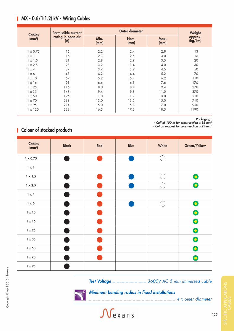
125
1 x 0.75
1 x 1
1 x 1.5
1 x 2.5
1 x 4
1 x 6
1 x 10
1 x 16
1 x 25
1 x 35
1 x 50
1 x 70
1 x 95
1 x 0.75 15 2.2 2.4 2.9 131 x 1 16 2.3 2.5 3.0 161 x 1.5 21 2.8 2.9 3.5 201 x 2.5 28 3.2 3.4 4.0 301 x 4 37 3.7 3.9 4.5 501 x 6 48 4.2 4.4 5.2 701 x 10 69 5.2 5.4 6.2 1101 x 16 91 6.6 6.8 7.6 1701 x 25 116 8.0 8.4 9.4 2701 x 35 148 9.4 9.8 11.0 3701 x 50 196 11.0 11.7 13.0 5101 x 70 238 13.0 13.5 15.0 7101 x 95 274 15.0 15.8 17.0 9501 x 120 322 16.5 17.2 18.5 1190
Cables (mm2)
Permissible current rating in open air
(A)
Outer diameter
Min.(mm)
Nom.(mm)
Max.(mm)
Weightapprox.(kg/km)
MX - 0.6/1(1.2) kV - Wiring Cables
Packaging : - Coil of 100 m for cross-section £ 16 mm2
- Cut on request for cross-section ≥ 25 mm2
Cables (mm2) Black Red Blue White Green/Yellow
Colour of stocked products
Cop
yrig
ht ©
Apr
il 20
13 -
Nex
ans
Test Voltage 3600V AC 5 min immersed cable
Minimum bending radius in fixed installations4 x outer diameter
r
SPEC
IFIC
APP
LICAT
ION
SC
ABL
ES
Exe17_NEXANS_catal_MARINE_avril2013 14/05/13 19:01 Page125

126
Core Identification
MPRXCX® EMCand MPRXCX® FLEXISHIP® EMC
Cables for variable frequency drives
Design
Marking
5. Screen/ArmouringCopper/Polyester tapeBare copper braid
6. Outer sheathPolyolefin SHF1Colour: blackSHF2 on request
NEXANS MPRXCX EMC Voltage«n» x «s» mm2 90°CIEC 60 332-22 «year» * *+ Metric Marking
Application
Standards• Construction & Design:IEC 60228IEC 60092-350IEC 60092-353• Tests performances:IEC 60332-3-22IEC 60332-1IEC 60754-1/60754-2IEC 61034• Materials:IEC 60092-351IEC 60092-359
0.6/1(1.2) kV1.8/3(3.6) kV
Motor supply cable for frequency converters controlled low voltage AC driveson ships, called VFD applications. MPRXCX® EMC cables are designed witha special coverage, copper-polyester tape and braid, which provide a 100%EMC protection. Insulation with low dielectric constant is used to reducereflected wave voltage peak magnitude.Symmetrical insulated ground wires, placed in corner, can reduce reflectedwave and return common mode noisy currents back to the drive.Enhanced insulation is implement for 0.6/1(1.2)kV cable to fulfill periodicpeak voltage up to 2xU=2kV due to harmonics.1.8/3(3.6)kV cable secure 3kV periodic peak voltage.These cables are used on board of ships in all locations for fixed installations.
3 cores: black-grey-brown4 cores:phases: black-grey-brownearth: split in 3 conductors
1. ConductorStranded or flexible bare copperClass 2 or class 5
2. Insulation (enhanced)XLPE(cross-linked polyethylene)
3. OptionnalReturn earth conductor
4. Inner coveringLapped or extruded
Max conductortemperature: 90 °C
1
3
5
2
6
4
ClBrF
ClClClClClClClClClClClBrBrBrBrBrBrBrFFFFFFF
-30 to 80 °CNo corrosivityIEC 60754-2
No toxicityLow smokeIEC 61034
Halogen freeIEC 60754-1
Fire retardantIEC 60332-3-22
Flame retardantIEC 60332-1
EMIHigh protection
Exe17_NEXANS_catal_MARINE_avril2013 14/05/13 19:01 Page126

127
MPRXCX® EMC - 0.6/1 (1.2) kV
3 x 70 144 33.5 34.7 37.0 2 7903 x 95 174 37.0 38.5 41.0 3 3903 x 120 201 41.5 43.3 46.0 4 3103 x 150 232 46.0 47.7 51.0 5 300
3 x 70 + 3 G 16 144 33.5 34.7 37.0 3 2303 x 95 + 3 G 16 174 37.0 38.5 41.0 3 8303 x 120 + 3 G 25 201 41.5 43.3 46.0 4 9903 x 150 + 3 G 25 232 46.0 47.7 51.0 5 980
Cables
(mm2)
Permissible currentrating in open air
(A)
Outer diameter
Min.(mm)
Nom.(mm)
Max.(mm)
Weightapprox.
(kg/km)
Products on request
MPRXCX® FLEXISHIP® EMC - 0.6/1 (1.2) kV
3 x 70 144 35.0 36.6 39.0 3 1003 x 95 174 40.0 41.3 44.0 3 8703 x 120 201 44.5 46.2 49.0 4 9103 x 150 232 49.5 51.3 54.5 6 080
3 x 70 + 3 G 16 144 35.0 36.6 39.0 3 5003 x 95 + 3 G 16 174 40.0 41.3 44.0 4 2703 x 120 + 3 G 25 201 44.5 46.2 49.0 5 5103 x 150 + 3 G 25 232 49.5 51.3 54.5 6 680
Cables
(mm2)
Permissible currentrating in open air
(A)
Outer diameter
Min.(mm)
Nom.(mm)
Max.(mm)
Weightapprox.
(kg/km)
Test Voltage Voltage test between phases conductors 5 kV in AC
Minimum bending radius in fixed installations• class 2 6 x outer diameter• class 5 5 x outer diameter
r
Cop
yrig
ht ©
Apr
il 20
13 -
Nex
ans
MPRXCX® FLEXISHIP® EMC - 1.8/3 (3.6) kV
3 x 70 144 38.5 39.8 42.5 3 3503 x 95 174 44.0 45.6 48.5 4 3803 x 120 201 47.0 48.6 52.0 5 1703 x 150 232 51.0 52.9 56.5 6 290
3 x 70 + 3 G 16 144 38.5 39.8 42.5 3 7503 x 95 + 3 G 16 174 44.0 45.6 48.5 4 7803 x 120 + 3 G 25 201 47.0 48.6 52.0 5 7703 x 150 + 3 G 25 232 51.0 52.9 56.5 6 890
Cables
(mm2)
Permissible currentrating in open air
(A)
Outer diameter
Min.(mm)
Nom.(mm)
Max.(mm)
Weightapprox.
(kg/km)
SPEC
IFIC
APP
LICAT
ION
SC
ABL
ES
Exe17_NEXANS_catal_MARINE_avril2013 14/05/13 19:01 Page127

128
Core Identification
MPRX® CABCables for Cabins
Design
Marking
3. Outer sheathSHF1 compoundColour: black
NEXANS MPRX CAB300/500 V 90°C«WW/YY»* *
+ Metric Marking
Application
Standards• Construction & Design :IEC 60228• Tests PerformancesIEC 60332-3-22IEC 60332-1IEC 60754-1/60754-2IEC 61034• MaterialsIEC 60092-351IEC 60092-359
300/500VThese cables are designed for cabin walls where space is limited, and needsreduced sized cables.
3 cores: brown-blue-green/yellow
1. ConductorFlexible bare copperClass 5
2. InsulationXLPE(Cross linked Polyethylene)
1
2
3
Max conductor temperature: 90 °C
ClBrF
ClClClClClClClClClClBrBrBrBrBrBrBrFFFFFFF
-30 to 80°CNo corrosivityIEC 60754-2
No toxicityFlexibleHalogen freeIEC 60754-1
Low smokeIEC 61034
Fire retardantIEC 60332-3 22
Flame retardantIEC 60332-1
Exe17_NEXANS_catal_MARINE_avril2013 14/05/13 19:01 Page128

129
3 G 1.5 6.4 6.6 7.2 903 G 2.5 7.3 7.6 8.2 120
Cables (mm2)
Outer diameter
Min.(mm)
Nom.(mm)
Max.(mm)
Weightapprox.(kg/km)
MPRX®-CAB - 300/500 V - Cables for Cabins
Products on request
Test Voltage 2.5 kV in AC between cores
Minimum bending radius in fixed installations• MPRX-CAB cl5 3 x outer diameter
r
Cop
yrig
ht ©
Apr
il 20
13 -
Nex
ans
SPEC
IFIC
APP
LICAT
ION
SC
ABL
ES
Exe17_NEXANS_catal_MARINE_avril2013 14/05/13 19:01 Page129

130
Core Identification
MPRX® F3 G 1.5
Design
MarkingNEXANS MPRX F 0.6/1kV 3 G 1.5 mm2
90°C IEC 60332-3-22«WW/YY»* * + Metric Marking
Standards• Construction & Design:IEC 60228IEC 60092-350• Tests performances:IEC 60332-3-22IEC 60332-1IEC 60754-1/60754-2IEC 61034• Materials:IEC 60092-351IEC 60092-359
0.6/1 (1.2) kVMPRX® F cable type is used for lighting distribution on board of ships in allpublic areas complying with IEC standards 60092-352. MPRX® F type withstands the IEC 60332-3-22 fire test on bunched cables andperforms to the SOLAS requirements. All materials used to produce this cableare halogen free. This design ensures that non corrosive and low toxic gasesare emitted in case of fire. Therefore, this cable type is especially designed forinstallations on passenger ships.
brown-green/yellow-blue
11 x 5 mmpermissible current ratingin open air: 16 A
1. ConductorStranded bare copperclass 2
2. InsulationXLPE(cross linked polyethylene)
3. Outer sheathPolyolefin SHF1Colour: green or red
Max conductor temperature: 90°C
1
2
3
Application
Dimensions
ClBrF
ClClClClClClClClClClBrBrBrBrBrBrBrFFFFFFF
-30 + 80 °CNo corrosivityIEC 60754-2
No toxicityLow smokeIEC 61034
Halogen freeIEC 60754-1
Fire retardantIEC 60332-3-22
Flame retardantIEC 60332-1
Exe17_NEXANS_catal_MARINE_avril2013 14/05/13 19:01 Page130

131
Cop
yrig
ht ©
Apr
il 20
13 -
Nex
ans
SPEC
IFIC
APP
LICAT
ION
SC
ABL
ES
Exe17_NEXANS_catal_MARINE_avril2013 14/05/13 19:01 Page131

132
ClBrF
ClClClClClClClClClClBrBrBrBrBrBrBrFFFFFFF EMI
-30 + 80°CNo corrosivityIEC 60754-2
No toxicityLow smokeIEC 61034
Halogen freeIEC 60754-1
Fire retardantIEC 60332-3-22
Core Identification
BMKHC (I)Control
Design
Marking
Insulation : XLPE(cross linked polyethylene)Colour white with blacknumbersProtective: green-yellow
4. Common coveringRubber compound
5. ArmouringBare copper wire braid
6. Outer sheathPolyolefin SHF1Colour: black
NEXANS BMKHC (I)(1x2x0.75)C + 3G2.5RM250 V IEC 60332-3-22 «year»+ Metric Marking
Application
Standards• Construction & Design:IEC 60092-350IEC 60092-376• Tests performances:IEC 60332-3-22IEC 60332-1IEC 60754-1/60754-2IEC 61034• Materials:IEC 60092-351IEC 60092-359
150/250 (300) VBus cable with integrated power supply for fixed installations incommunication-radio, control and data processing facilities on ships andoffshore units in all locations and open decks.
Power cores : white with printed number 3+ green/yellowControl cores : black-blue
1. Control coresStranded bare copper (class 2)Cross section area: 0.75mm2
Insulation : XLPE(cross linked polyethylene)
1a. Shielded (individual screened)Bare copper wire braid
2. Centre element
3. Power coresStanded bare copper (class 2)Cross section area: 2.5mm2
Max conductor temperature: 90°C
2
2
1
1
Flame retardantIEC 60332-1
2
3
4
5
6
1
Exe17_NEXANS_catal_MARINE_avril2013 14/05/13 19:01 Page132

133
(1 x 2 x 0.75)C + 3G2.5RM 17.1 19.0 20.0 500
Cables (mm2)
Outer diameter
Min.(mm)
Nom.(mm)
Max.(mm)
Weightapprox.(kg/km)
BMKHC (I) 150/250 (300) V - Control
Test Voltage 1500V AC
Minimum bending radius in fixed installations6 x outer diameter
r
Cop
yrig
ht ©
Apr
il 20
13 -
Nex
ans
SPEC
IFIC
APP
LICAT
ION
SC
ABL
ES
Exe17_NEXANS_catal_MARINE_avril2013 14/05/13 19:01 Page133

134
Core Identification
CCTV Camera Cable
Design
Marking
4. General ScreenTinned copper braid
5. Outer sheathSHF1 compoundColour: green
6. Screened pairFlexible tinned copper insulated with thin wall halogen free compoundScreen: tinned copper braidSheath: halogen free
7. Coaxial: 75 OhmsType RX6 with halogen free sheath
NEXANS referenceWW/YY
Standards• Tests performances:IEC 60332-3-22IEC 60332-1IEC 60754-1/60754-2IEC 61034• Materials:IEC 60092-359
This specific composite cables are designed to electronic equipment for CCTVcamerasv. Halogen Free and Low smoke materials have been used to protectpeople and installations on board.
• Triple AWG 16black-brown-G/Y (2PI919) and yellow-white-blue (2PJ399)
• Pair AWG 20 (2PJ914) or red-white-blue (2PJ399)n°1 = green-yellown°2 = white-brown
• Pair AWG 20 (2PJ399) white-blue
1. Triple AWG 16Flexible tinned copper insulatedwith halogen free compoundthin wall
2. Screened Pair AWG 20Flexible tinned copper insulatedwith thin wall halogen freecompoundscreen: aluminium/polyestertape and drain wire
3. Coaxial: 75 OhmsType RG59U withhalogen free sheath
Application
-25 + 70 °CLow corrosivityIEC 60754-2
Low toxicityLow smokeIEC 61034
Fire retardantIEC 60332-1
Flame retardantIEC 60332-3-22
ClBrF
ClClClClClClClClClClBrBrBrBrBrBrBrFFFFFFF
Halogen freeIEC 60754-1
7
1
6
3
45
2
Exe17_NEXANS_catal_MARINE_avril2013 14/05/13 19:01 Page134

135
2 PI 919 12.5 / 13.5 215 1302 PJ 399 19.4 / 20.6 510 200
Nexans reference Cable diameter(mm)
Weight Approx.(kg/km)
Minimum Bending Radius(mm)
CCTV - Camera Cable
Electrical Characteristics
2 PI 919 : . . . . . . . . . . . . . . . . . . .RG59 + 2 (2 x 0.6) + 1 (3 x 1.34)2 PJ 399 : . . . . . . . . . . . . . . . . . . . . .KX6 + 2 (2 x 0.6) + 2 (3 x 2.08)
Cop
yrig
ht ©
Apr
il 20
13 -
Nex
ans
TRIPLE (UNSCREENED)AWG 16 = 1.34 mm2
TRIPLE (UNSCREENED)AWG 14 = 2.08 mm2
2 PI 919 2 PJ 399
SCREENED PAIRAWG 20 = 0.60 mm2
SCREENED PAIRAWG 20 = 0.60 mm2
COAXIAL 75 Ωtype RG 59 U
COAXIAL 75 Ωtype KX6
• Triple conductor electrical resistance at 20°C £ 13.7 Ω/km £ 8.2 Ω/km• Triple voltage rate up to 250V up to 250V• Triple core diameter 2.10 mm 2.60 mm
• Pair conductor electrical resistance at 20°C £ 33 Ω/km £ 33 Ω/km• Pair voltage rate up to 250V up to 250V• Pair core diameter 1.50 mm 1.50 mm
• Type Solid bare 0.81 mm 7 x 0.20 mm - Tinned copper• Characteristic impedance 75 Ω ± 4 Ω 75 Ω ± 3 Ω at 200 MHz• Conductor electrical resistance at 20°C £ 39 Ω/km -• Nominal capacitance 54pF/km -• Attenuation at
10 MHz 2.8 dB/100m -50 MHz 6.2 dB/100m -100 MHz 8.9 dB/100m -200 MHz 12.8 dB/100m 20 dB/100m500 MHz 23.0 dB/100m -
• Diameter - 6.10 mm ± 0.15 mm
SPEC
IFIC
APP
LICAT
ION
SC
ABL
ES
Exe17_NEXANS_catal_MARINE_avril2013 14/05/13 19:01 Page135

136
Exe17_NEXANS_catal_MARINE_avril2013 14/05/13 19:01 Page136

137
Cop
yrig
ht ©
Apr
il 20
13 -
Nex
ans
Exe17_NEXANS_catal_MARINE_avril2013 14/05/13 19:01 Page137

138
Exe17_NEXANS_catal_MARINE_avril2013 14/05/13 19:01 Page138

Cop
yrig
ht ©
Apr
il 20
13 -
Nex
ans
This catalogue shows a general description of products which characteristics are not contratual in any case. NEXANS reserves the right to change specifications without prior notice. All total or partial reproduction, donewithout NEXANS authorization is unlawful.
Exe17_NEXANS_catal_MARINE_avril2013 14/05/13 19:01 Page139

Cop
yrig
ht ©
Apr
il 20
13 -
Nex
ans
Doc
umen
t prin
ted
on p
aper
100
% C
ert.
N°P
EFC
/10-
31-1
587
from
sus
tain
ably
-man
aged
fore
st.
With energy at the basis of its development, Nexans,worldwide expert in the cable industry, offers an extensiverange of cables and cabling solutions. The Group is aglobal player in the energy transmission and distribution,industry and building markets. Nexans addresses a wideseries of market segments: from energy and telecomnetworks to energy resources (wind turbines, photovoltaic,oil and gas, and mining) to transportation (shipbuilding,aerospace, automotive and automation, and railways).
Nexans is a responsible industrial company that regardssustainable development as integral to its global andoperational strategy. Continuous innovation in products,solutions and services, employee development andcommitment, customer orientation and the introduction ofsafe industrial processes with limited environmental impactare among the key initiatives that place Nexans at thecore of a sustainable future.
With an industrial presence in 40 countries andcommercial activities worldwide, Nexans employs25,000 people and had sales in 2012 of nearly 7.2 billion euros. Nexans is listed on NYSE EuronextParis, compartment A.
For more information, please consult: www.nexans.com
For further information, please contact us at:
www.nexans.com www.nexans.com/shipbuilding
Global�expert�in�cables�and�cabling�systems
Exe17_NEXANS_catal_MARINE_avril2013 14/05/13 19:01 Page140