shit just got real
DESCRIPTION
noneTRANSCRIPT

SW820-AP-MMI-010 REVISION 15 27 MARCH 2009
SW820-AP-MMI-010REVISION 15
TECHNICAL MANUALTOMAHAWK CRUISE MISSILE RGM/UGM-109
SYSTEM DESCRIPTION
THIS DOCUMENT SUPERSEDES SW820-AP-MMI-010 REVISION 14 DATED 15 MARCH 2008.
DISTRIBUTION STATEMENT D: Distribution authorized to the Department of Defense and U.S.DOD contractors only; administrative or operational use: 7 April 1998. Other requestsfor this document shall be referred to Program Executive Officer for Unmanned Aviationand Strike Weapons [PEO(U&W)].
WARNING: This document contains technical data whose export is restricted by the Arms ExportControl Act (Title 22, U.S.C., Sec 2751, et seq.) or the Export Administration Act of 1979, asamended, (Title 50, U.S.C., App. 2401 et seq.). Violations of these export laws are subjectto severe criminal penalties. Disseminate in accordance with provisions of DoD Directive5230.25.
DESTRUCTION NOTICE: Destroy by any method that will prevent disclosure of contents orreconstruction of the document.
PUBLISHED BY DIRECTION OF PROGRAM EXECUTIVE OFFICER FOR UNMANNEDAVIATION AND STRIKE WEAPONS
27 March 2009
1

SW820-AP-MMI-010 REVISION 15 27 MARCH 2009
TABLE OF CONTENTSFOREWORD... . . . . . . . . . . . . . . . . . . . . . . . . . . . . . . . . . . . . . . . . . . . . . . . . . . . . . . . . . . . . . . . . . . . . . . . . . . . . . . . . . . . . . . . . . . . 17CHAPTER 1 INTRODUCTION ... . . . . . . . . . . . . . . . . . . . . . . . . . . . . . . . . . . . . . . . . . . . . . . . . . . . . . . . . . . . . . . . . . . . . 19SECTION I. DOCUMENT ORGANIZATION ... . . . . . . . . . . . . . . . . . . . . . . . . . . . . . . . . . . . . . . . . . . . . . . . . 191.1 SCOPE. .. . . . . . . . . . . . . . . . . . . . . . . . . . . . . . . . . . . . . . . . . . . . . . . . . . . . . . . . . . . . . . . . . . . . . . . . . . . . . . . . . . . . . . . . . 191.1.1 Chapter 1. . . . . . . . . . . . . . . . . . . . . . . . . . . . . . . . . . . . . . . . . . . . . . . . . . . . . . . . . . . . . . . . . . . . . . . . . . . . . . . . . . 191.1.2 Chapter 2. . . . . . . . . . . . . . . . . . . . . . . . . . . . . . . . . . . . . . . . . . . . . . . . . . . . . . . . . . . . . . . . . . . . . . . . . . . . . . . . . . 191.1.3 Chapter 3. . . . . . . . . . . . . . . . . . . . . . . . . . . . . . . . . . . . . . . . . . . . . . . . . . . . . . . . . . . . . . . . . . . . . . . . . . . . . . . . . . 191.1.4 Chapter 4. . . . . . . . . . . . . . . . . . . . . . . . . . . . . . . . . . . . . . . . . . . . . . . . . . . . . . . . . . . . . . . . . . . . . . . . . . . . . . . . . . 19
SECTION II. TOMAHAWKWEAPON SYSTEM... . . . . . . . . . . . . . . . . . . . . . . . . . . . . . . . . . . . . . . . . . . . . 201.2 TWS DESCRIPTION... . . . . . . . . . . . . . . . . . . . . . . . . . . . . . . . . . . . . . . . . . . . . . . . . . . . . . . . . . . . . . . . . . . . . . . . 201.3 MISSION. .. . . . . . . . . . . . . . . . . . . . . . . . . . . . . . . . . . . . . . . . . . . . . . . . . . . . . . . . . . . . . . . . . . . . . . . . . . . . . . . . . . . . . . 201.4 ALL-UP-ROUND. .. . . . . . . . . . . . . . . . . . . . . . . . . . . . . . . . . . . . . . . . . . . . . . . . . . . . . . . . . . . . . . . . . . . . . . . . . . . . 201.4.1 Tactical AURs. . . . . . . . . . . . . . . . . . . . . . . . . . . . . . . . . . . . . . . . . . . . . . . . . . . . . . . . . . . . . . . . . . . . . . . . . . . . 201.4.2 Exercise AURs. .. . . . . . . . . . . . . . . . . . . . . . . . . . . . . . . . . . . . . . . . . . . . . . . . . . . . . . . . . . . . . . . . . . . . . . . . . 21
1.5 MISSILE IDENTIFICATION SYSTEM.... . . . . . . . . . . . . . . . . . . . . . . . . . . . . . . . . . . . . . . . . . . . . . . . . 211.6 SUPPORT EQUIPMENT. .. . . . . . . . . . . . . . . . . . . . . . . . . . . . . . . . . . . . . . . . . . . . . . . . . . . . . . . . . . . . . . . . . . . 211.7 LOADING AND HANDLING TRAINING EQUIPMENT... . . . . . . . . . . . . . . . . . . . . . . . . . . . 211.8 DOCUMENTATION. .. . . . . . . . . . . . . . . . . . . . . . . . . . . . . . . . . . . . . . . . . . . . . . . . . . . . . . . . . . . . . . . . . . . . . . . . 221.8.1 Record Books. . . . . . . . . . . . . . . . . . . . . . . . . . . . . . . . . . . . . . . . . . . . . . . . . . . . . . . . . . . . . . . . . . . . . . . . . . . . . 221.8.2 Procedural Documentation. . . . . . . . . . . . . . . . . . . . . . . . . . . . . . . . . . . . . . . . . . . . . . . . . . . . . . . . . . . . . . 221.8.2.1 Figures. . . . . . . . . . . . . . . . . . . . . . . . . . . . . . . . . . . . . . . . . . . . . . . . . . . . . . . . . . . . . . . . . . . . . . . . . . . . . . . . 221.8.2.2 Evolutions. . . . . . . . . . . . . . . . . . . . . . . . . . . . . . . . . . . . . . . . . . . . . . . . . . . . . . . . . . . . . . . . . . . . . . . . . . . . 22
1.8.3 Procedural Documentation Terminology. . . . . . . . . . . . . . . . . . . . . . . . . . . . . . . . . . . . . . . . . . . . . . 231.8.3.1 Procedural Guides. . . . . . . . . . . . . . . . . . . . . . . . . . . . . . . . . . . . . . . . . . . . . . . . . . . . . . . . . . . . . . . . . . . 231.8.3.2 Operating Procedures. . . . . . . . . . . . . . . . . . . . . . . . . . . . . . . . . . . . . . . . . . . . . . . . . . . . . . . . . . . . . . . 231.8.3.3 Inspection Table Specifics. . . . . . . . . . . . . . . . . . . . . . . . . . . . . . . . . . . . . . . . . . . . . . . . . . . . . . . . . 231.8.3.4 Standard Inspection Procedures. . . . . . . . . . . . . . . . . . . . . . . . . . . . . . . . . . . . . . . . . . . . . . . . . . . 241.8.3.5 Supervisors. . . . . . . . . . . . . . . . . . . . . . . . . . . . . . . . . . . . . . . . . . . . . . . . . . . . . . . . . . . . . . . . . . . . . . . . . . . 241.8.3.6 Readers. . . . . . . . . . . . . . . . . . . . . . . . . . . . . . . . . . . . . . . . . . . . . . . . . . . . . . . . . . . . . . . . . . . . . . . . . . . . . . . 241.8.3.7 Workers. . . . . . . . . . . . . . . . . . . . . . . . . . . . . . . . . . . . . . . . . . . . . . . . . . . . . . . . . . . . . . . . . . . . . . . . . . . . . . . 241.8.3.8 Observers. . . . . . . . . . . . . . . . . . . . . . . . . . . . . . . . . . . . . . . . . . . . . . . . . . . . . . . . . . . . . . . . . . . . . . . . . . . . . 24
1.8.4 Quality Assurance (QA). . . . . . . . . . . . . . . . . . . . . . . . . . . . . . . . . . . . . . . . . . . . . . . . . . . . . . . . . . . . . . . . . 241.8.4.1 Philosophy and Scope. . . . . . . . . . . . . . . . . . . . . . . . . . . . . . . . . . . . . . . . . . . . . . . . . . . . . . . . . . . . . . 241.8.4.2 QA Functions and Responsibilities. . . . . . . . . . . . . . . . . . . . . . . . . . . . . . . . . . . . . . . . . . . . . . . 251.8.4.3 IP Stop Points. . . . . . . . . . . . . . . . . . . . . . . . . . . . . . . . . . . . . . . . . . . . . . . . . . . . . . . . . . . . . . . . . . . . . . . . 25
1.8.5 Reference Documentation. .. . . . . . . . . . . . . . . . . . . . . . . . . . . . . . . . . . . . . . . . . . . . . . . . . . . . . . . . . . . . . 251.8.6 Abbreviations and Acronyms. . . . . . . . . . . . . . . . . . . . . . . . . . . . . . . . . . . . . . . . . . . . . . . . . . . . . . . . . . . 25
1.9 REPORTS. .. . . . . . . . . . . . . . . . . . . . . . . . . . . . . . . . . . . . . . . . . . . . . . . . . . . . . . . . . . . . . . . . . . . . . . . . . . . . . . . . . . . . . 25SECTION III. TOMAHAWK CRUISE MISSILE ... . . . . . . . . . . . . . . . . . . . . . . . . . . . . . . . . . . . . . . . . . . . . . 261.10 GENERAL... . . . . . . . . . . . . . . . . . . . . . . . . . . . . . . . . . . . . . . . . . . . . . . . . . . . . . . . . . . . . . . . . . . . . . . . . . . . . . . . . . . 261.11 TACTICAL VARIANTS... . . . . . . . . . . . . . . . . . . . . . . . . . . . . . . . . . . . . . . . . . . . . . . . . . . . . . . . . . . . . . . . . . . 261.11.1 Land-Attack 109A. ... . . . . . . . . . . . . . . . . . . . . . . . . . . . . . . . . . . . . . . . . . . . . . . . . . . . . . . . . . . . . . . . . . . 26
2

SW820-AP-MMI-010 REVISION 15 27 MARCH 2009
1.11.1.1 Guidance Section. . . . . . . . . . . . . . . . . . . . . . . . . . . . . . . . . . . . . . . . . . . . . . . . . . . . . . . . . . . . . . . . . . 261.11.1.2 Forward Body Payload Section. . . . . . . . . . . . . . . . . . . . . . . . . . . . . . . . . . . . . . . . . . . . . . . . . . 261.11.1.3 Forward Body Fuel Section. .. . . . . . . . . . . . . . . . . . . . . . . . . . . . . . . . . . . . . . . . . . . . . . . . . . . . 26
1.11.2 Land-Attack 109C. .. . . . . . . . . . . . . . . . . . . . . . . . . . . . . . . . . . . . . . . . . . . . . . . . . . . . . . . . . . . . . . . . . . . . 261.11.2.1 Forward Body Guidance Section. . . . . . . . . . . . . . . . . . . . . . . . . . . . . . . . . . . . . . . . . . . . . . . . 271.11.2.2 Forward Body Payload Section. . . . . . . . . . . . . . . . . . . . . . . . . . . . . . . . . . . . . . . . . . . . . . . . . . 27
1.11.3 Land-Attack 109D. ... . . . . . . . . . . . . . . . . . . . . . . . . . . . . . . . . . . . . . . . . . . . . . . . . . . . . . . . . . . . . . . . . . . 271.11.3.1 Forward Body Guidance Section. . . . . . . . . . . . . . . . . . . . . . . . . . . . . . . . . . . . . . . . . . . . . . . . 281.11.3.2 Forward Body Payload Section. . . . . . . . . . . . . . . . . . . . . . . . . . . . . . . . . . . . . . . . . . . . . . . . . . 28
1.11.4 Block IV Tactical TOMAHAWK. .. . . . . . . . . . . . . . . . . . . . . . . . . . . . . . . . . . . . . . . . . . . . . . . . . . . 291.11.4.1 Forward Body Section. . . . . . . . . . . . . . . . . . . . . . . . . . . . . . . . . . . . . . . . . . . . . . . . . . . . . . . . . . . . 291.11.4.2 Midbody Section. . . . . . . . . . . . . . . . . . . . . . . . . . . . . . . . . . . . . . . . . . . . . . . . . . . . . . . . . . . . . . . . . . . 291.11.4.3 Aftbody and Tailcone Section. .. . . . . . . . . . . . . . . . . . . . . . . . . . . . . . . . . . . . . . . . . . . . . . . . . 301.11.4.3.1 Air Data Module (ADM). . . . . . . . . . . . . . . . . . . . . . . . . . . . . . . . . . . . . . . . . . . . . . . . . . . . 311.11.4.3.2 Alternator Voltage Control Converter (AVCC). .. . . . . . . . . . . . . . . . . . . . . . . . . 311.11.4.3.3 Anti-Jam Global Positioning System Antenna. .. . . . . . . . . . . . . . . . . . . . . . . . . 311.11.4.3.4 Anti-Jam Global Positioning System Receiver (AGR). .. . . . . . . . . . . . . . . . 311.11.4.3.5 Cruise Missile Airframe (CMA) Battery. . . . . . . . . . . . . . . . . . . . . . . . . . . . . . . . . . 311.11.4.3.6 Digital Scene Matching Area Correlator Processor Subsystem. .. . . . . . 321.11.4.3.7 Digital Scene Matching Area Correlator Sensor Assembly. .. . . . . . . . . . 321.11.4.3.8 Fin Control System. .. . . . . . . . . . . . . . . . . . . . . . . . . . . . . . . . . . . . . . . . . . . . . . . . . . . . . . . . . 321.11.4.3.9 Guidance Electronics Unit (GEU). . . . . . . . . . . . . . . . . . . . . . . . . . . . . . . . . . . . . . . . . . 321.11.4.3.10 Mission Control Input/Output (MCIO). . . . . . . . . . . . . . . . . . . . . . . . . . . . . . . . . . 321.11.4.3.11 Mission Control Processor (MCP). . . . . . . . . . . . . . . . . . . . . . . . . . . . . . . . . . . . . . . . 321.11.4.3.12 Navigation Processor (NP). . . . . . . . . . . . . . . . . . . . . . . . . . . . . . . . . . . . . . . . . . . . . . . . . 321.11.4.3.13 Power Filter Unit (PFU). . . . . . . . . . . . . . . . . . . . . . . . . . . . . . . . . . . . . . . . . . . . . . . . . . . . 331.11.4.3.14 Pyro and Power Control Assembly (PPCA). . . . . . . . . . . . . . . . . . . . . . . . . . . . . 331.11.4.3.15 Radar Altimeter (RA). . . . . . . . . . . . . . . . . . . . . . . . . . . . . . . . . . . . . . . . . . . . . . . . . . . . . . . 331.11.4.3.16 Satellite Data Link (SDL) Antenna. .. . . . . . . . . . . . . . . . . . . . . . . . . . . . . . . . . . . . . 331.11.4.3.17 Satellite Communications (SATCOM) Data Link Terminal. . . . . . . . . . 331.11.4.3.18 Secondary Power Unit (SPU). .. . . . . . . . . . . . . . . . . . . . . . . . . . . . . . . . . . . . . . . . . . . 33
1.11.5 TCM Body Sections Common to 109A/C/D. .. . . . . . . . . . . . . . . . . . . . . . . . . . . . . . . . . . . . . . 331.11.5.1 Midbody Section. . . . . . . . . . . . . . . . . . . . . . . . . . . . . . . . . . . . . . . . . . . . . . . . . . . . . . . . . . . . . . . . . . . 331.11.5.2 Aft Body Section. .. . . . . . . . . . . . . . . . . . . . . . . . . . . . . . . . . . . . . . . . . . . . . . . . . . . . . . . . . . . . . . . . 341.11.5.3 Propulsion Section. . . . . . . . . . . . . . . . . . . . . . . . . . . . . . . . . . . . . . . . . . . . . . . . . . . . . . . . . . . . . . . . . 34
1.11.6 Rocket Motor Assemblies. . . . . . . . . . . . . . . . . . . . . . . . . . . . . . . . . . . . . . . . . . . . . . . . . . . . . . . . . . . . . 341.11.6.1 Mk 106 Mod 0 Rocket Motor. . . . . . . . . . . . . . . . . . . . . . . . . . . . . . . . . . . . . . . . . . . . . . . . . . . . 341.11.6.2 Mk 111 Mod 0 Rocket Motor. . . . . . . . . . . . . . . . . . . . . . . . . . . . . . . . . . . . . . . . . . . . . . . . . . . . 341.11.6.3 Mk 135 Rocket Motor Assembly. .. . . . . . . . . . . . . . . . . . . . . . . . . . . . . . . . . . . . . . . . . . . . . . 35
1.11.7 TCM Components Common to 109A/C/D. .. . . . . . . . . . . . . . . . . . . . . . . . . . . . . . . . . . . . . . . . 351.11.7.1 Missile Retention Devices. . . . . . . . . . . . . . . . . . . . . . . . . . . . . . . . . . . . . . . . . . . . . . . . . . . . . . . . 351.11.7.2 Underwater Protection Devices. . . . . . . . . . . . . . . . . . . . . . . . . . . . . . . . . . . . . . . . . . . . . . . . . . 351.11.7.2.1 Wing Slot Plugs. . . . . . . . . . . . . . . . . . . . . . . . . . . . . . . . . . . . . . . . . . . . . . . . . . . . . . . . . . . . . . . 35
3

SW820-AP-MMI-010 REVISION 15 27 MARCH 2009
1.11.7.2.2 Engine Inlet Cover. . . . . . . . . . . . . . . . . . . . . . . . . . . . . . . . . . . . . . . . . . . . . . . . . . . . . . . . . . . 351.11.7.2.3 Continuity Shroud. .. . . . . . . . . . . . . . . . . . . . . . . . . . . . . . . . . . . . . . . . . . . . . . . . . . . . . . . . . . 35
1.12 EXERCISE VARIANTS. .. . . . . . . . . . . . . . . . . . . . . . . . . . . . . . . . . . . . . . . . . . . . . . . . . . . . . . . . . . . . . . . . . . . 361.12.1 Recovery Exercise Module Equipped Missile. . . . . . . . . . . . . . . . . . . . . . . . . . . . . . . . . . . . . . 361.12.1.1 Parachute Compartment. . . . . . . . . . . . . . . . . . . . . . . . . . . . . . . . . . . . . . . . . . . . . . . . . . . . . . . . . . 361.12.1.2 Riser Stowage Compartment. . . . . . . . . . . . . . . . . . . . . . . . . . . . . . . . . . . . . . . . . . . . . . . . . . . . . 361.12.1.3 Flotation Equipment Compartment. . . . . . . . . . . . . . . . . . . . . . . . . . . . . . . . . . . . . . . . . . . . . 361.12.1.4 Instrumentation/Avionics Compartment. . . . . . . . . . . . . . . . . . . . . . . . . . . . . . . . . . . . . . . . 36
1.12.2 Range Safety System Equipped Missile. . . . . . . . . . . . . . . . . . . . . . . . . . . . . . . . . . . . . . . . . . . . . 371.12.3 Midbody Range Safety Subsystem (MRSS). . . . . . . . . . . . . . . . . . . . . . . . . . . . . . . . . . . . . . . . 37
1.13 LAND-ATTACK TCM TARGETING. .. . . . . . . . . . . . . . . . . . . . . . . . . . . . . . . . . . . . . . . . . . . . . . . . . . . 371.13.1 Mission Data. . . . . . . . . . . . . . . . . . . . . . . . . . . . . . . . . . . . . . . . . . . . . . . . . . . . . . . . . . . . . . . . . . . . . . . . . . . . 371.13.2 Terrain Contour Matching (TERCOM). .. . . . . . . . . . . . . . . . . . . . . . . . . . . . . . . . . . . . . . . . . . . . 371.13.3 Digital Scene Matching Area Correlation (DSMAC). . . . . . . . . . . . . . . . . . . . . . . . . . . . . . 381.13.4 Global Positioning System Subsystem (GPSS). . . . . . . . . . . . . . . . . . . . . . . . . . . . . . . . . . . . . 381.13.5 Block IV Tactical TOMAHAWK Targeting. . . . . . . . . . . . . . . . . . . . . . . . . . . . . . . . . . . . . . . . 38
1.14 TYPICAL MISSION PROFILE. .. . . . . . . . . . . . . . . . . . . . . . . . . . . . . . . . . . . . . . . . . . . . . . . . . . . . . . . . . . 391.14.1 Prelaunch Phase. . . . . . . . . . . . . . . . . . . . . . . . . . . . . . . . . . . . . . . . . . . . . . . . . . . . . . . . . . . . . . . . . . . . . . . . . 391.14.2 Launch Phase. . . . . . . . . . . . . . . . . . . . . . . . . . . . . . . . . . . . . . . . . . . . . . . . . . . . . . . . . . . . . . . . . . . . . . . . . . . . 391.14.3 Boost Phase. .. . . . . . . . . . . . . . . . . . . . . . . . . . . . . . . . . . . . . . . . . . . . . . . . . . . . . . . . . . . . . . . . . . . . . . . . . . . . 391.14.4 Transition to Cruise Flight. . . . . . . . . . . . . . . . . . . . . . . . . . . . . . . . . . . . . . . . . . . . . . . . . . . . . . . . . . . . . 401.14.5 Cruise Phase. . . . . . . . . . . . . . . . . . . . . . . . . . . . . . . . . . . . . . . . . . . . . . . . . . . . . . . . . . . . . . . . . . . . . . . . . . . . . 401.14.6 Terminal Phase (109A/C). . . . . . . . . . . . . . . . . . . . . . . . . . . . . . . . . . . . . . . . . . . . . . . . . . . . . . . . . . . . . . 401.14.7 Target Attack Phase (109D). . . . . . . . . . . . . . . . . . . . . . . . . . . . . . . . . . . . . . . . . . . . . . . . . . . . . . . . . . . 401.14.8 Block IV TACTOM Terminal Phase. . . . . . . . . . . . . . . . . . . . . . . . . . . . . . . . . . . . . . . . . . . . . . . . . 411.14.9 Recovery Phase (REM-equipped variants). . . . . . . . . . . . . . . . . . . . . . . . . . . . . . . . . . . . . . . . . . 41
SECTION IV. TORPEDO TUBE LAUNCH CONFIGURATION ... . . . . . . . . . . . . . . . . . . . . . . . . . . 421.15 AUR IDENTIFICATION. .. . . . . . . . . . . . . . . . . . . . . . . . . . . . . . . . . . . . . . . . . . . . . . . . . . . . . . . . . . . . . . . . . . 421.16 CAPSULES... . . . . . . . . . . . . . . . . . . . . . . . . . . . . . . . . . . . . . . . . . . . . . . . . . . . . . . . . . . . . . . . . . . . . . . . . . . . . . . . . . 421.16.1 Capsule Mk 1 Mod 0. . . . . . . . . . . . . . . . . . . . . . . . . . . . . . . . . . . . . . . . . . . . . . . . . . . . . . . . . . . . . . . . . . . . 421.16.1.1 Nose Cover. . . . . . . . . . . . . . . . . . . . . . . . . . . . . . . . . . . . . . . . . . . . . . . . . . . . . . . . . . . . . . . . . . . . . . . . . 421.16.1.2 Nose Diaphragm. ... . . . . . . . . . . . . . . . . . . . . . . . . . . . . . . . . . . . . . . . . . . . . . . . . . . . . . . . . . . . . . . . 421.16.1.3 Capsule Barrel. . . . . . . . . . . . . . . . . . . . . . . . . . . . . . . . . . . . . . . . . . . . . . . . . . . . . . . . . . . . . . . . . . . . . 421.16.1.4 Alignment and Retention Provisions. . . . . . . . . . . . . . . . . . . . . . . . . . . . . . . . . . . . . . . . . . . 431.16.1.5 Sleeve. . . . . . . . . . . . . . . . . . . . . . . . . . . . . . . . . . . . . . . . . . . . . . . . . . . . . . . . . . . . . . . . . . . . . . . . . . . . . . . 431.16.1.6 Barrel Closure. . . . . . . . . . . . . . . . . . . . . . . . . . . . . . . . . . . . . . . . . . . . . . . . . . . . . . . . . . . . . . . . . . . . . . 431.16.1.7 Slot Covers. . . . . . . . . . . . . . . . . . . . . . . . . . . . . . . . . . . . . . . . . . . . . . . . . . . . . . . . . . . . . . . . . . . . . . . . . 431.16.1.8 Protective Covers. . . . . . . . . . . . . . . . . . . . . . . . . . . . . . . . . . . . . . . . . . . . . . . . . . . . . . . . . . . . . . . . . . 43
1.16.2 Capsule Mk 3 Mod 0. . . . . . . . . . . . . . . . . . . . . . . . . . . . . . . . . . . . . . . . . . . . . . . . . . . . . . . . . . . . . . . . . . . 431.16.2.1 Nose Cover. . . . . . . . . . . . . . . . . . . . . . . . . . . . . . . . . . . . . . . . . . . . . . . . . . . . . . . . . . . . . . . . . . . . . . . . . 431.16.2.2 Nose Diaphragm. ... . . . . . . . . . . . . . . . . . . . . . . . . . . . . . . . . . . . . . . . . . . . . . . . . . . . . . . . . . . . . . . . 441.16.2.3 Capsule Barrel. . . . . . . . . . . . . . . . . . . . . . . . . . . . . . . . . . . . . . . . . . . . . . . . . . . . . . . . . . . . . . . . . . . . . 441.16.2.4 Alignment and Retention Provisions. . . . . . . . . . . . . . . . . . . . . . . . . . . . . . . . . . . . . . . . . . . 44
4

SW820-AP-MMI-010 REVISION 15 27 MARCH 2009
1.16.2.5 Barrel Closure. . . . . . . . . . . . . . . . . . . . . . . . . . . . . . . . . . . . . . . . . . . . . . . . . . . . . . . . . . . . . . . . . . . . . . 441.16.2.6 Slot Covers. . . . . . . . . . . . . . . . . . . . . . . . . . . . . . . . . . . . . . . . . . . . . . . . . . . . . . . . . . . . . . . . . . . . . . . . . 441.16.2.7 Protective Covers. . . . . . . . . . . . . . . . . . . . . . . . . . . . . . . . . . . . . . . . . . . . . . . . . . . . . . . . . . . . . . . . . . 44
1.17 UMBILICAL ASSEMBLIES. .. . . . . . . . . . . . . . . . . . . . . . . . . . . . . . . . . . . . . . . . . . . . . . . . . . . . . . . . . . . . . 441.17.1 Electrical Umbilical. . . . . . . . . . . . . . . . . . . . . . . . . . . . . . . . . . . . . . . . . . . . . . . . . . . . . . . . . . . . . . . . . . . . 451.17.2 Pneumatic Umbilical. . . . . . . . . . . . . . . . . . . . . . . . . . . . . . . . . . . . . . . . . . . . . . . . . . . . . . . . . . . . . . . . . . . 45
1.18 INERT VARIANTS... . . . . . . . . . . . . . . . . . . . . . . . . . . . . . . . . . . . . . . . . . . . . . . . . . . . . . . . . . . . . . . . . . . . . . . . . 451.18.1 TOMAHAWK Test Missile (TOTEM) UTM-109-1. . . . . . . . . . . . . . . . . . . . . . . . . . . . . . . 451.18.2 Encapsulated No-Launch No-Wet TOTEM (NL TOTEM). . . . . . . . . . . . . . . . . . . . . . . 451.18.3 Crew Training Shape (CTS) UTM-109-1A. .. . . . . . . . . . . . . . . . . . . . . . . . . . . . . . . . . . . . . . . 451.18.4 Warhead Installation Trainer (WIT) Mk 35 Mod 0. . . . . . . . . . . . . . . . . . . . . . . . . . . . . . . . 451.18.5 TOMAHAWK Fitment Shape (TOMFISH) Mk 1 Mod 0. . . . . . . . . . . . . . . . . . . . . . . . . 461.18.6 Commercial Off The Shelf TOMAHAWK Test Missile (COTS TOTEM). . . . . 461.18.7 Pressure Vent Test Vehicle TOMAHAWK Test Missile (PVTV TOTEM). . . . . 46
1.19 CNU-308/E SHIPPING CONTAINER. ... . . . . . . . . . . . . . . . . . . . . . . . . . . . . . . . . . . . . . . . . . . . . . . . . 461.19.1 Function. . . . . . . . . . . . . . . . . . . . . . . . . . . . . . . . . . . . . . . . . . . . . . . . . . . . . . . . . . . . . . . . . . . . . . . . . . . . . . . . . . 461.19.2 Description. . . . . . . . . . . . . . . . . . . . . . . . . . . . . . . . . . . . . . . . . . . . . . . . . . . . . . . . . . . . . . . . . . . . . . . . . . . . . . . 46
1.20 RECORD BOOKS... . . . . . . . . . . . . . . . . . . . . . . . . . . . . . . . . . . . . . . . . . . . . . . . . . . . . . . . . . . . . . . . . . . . . . . . . . 461.20.1 PEO(W) PUB 4440, Record Book for Tomahawk Cruise Missile. . . . . . . . . . . . . . . 471.20.2 CMP PUB 4440/2, Record Book for TOMAHAWK Test Missile (TOTEM). . 47
1.21 WEIGHTS AND CENTERS OF GRAVITY. .. . . . . . . . . . . . . . . . . . . . . . . . . . . . . . . . . . . . . . . . . . . . 47SECTION V. CAPSULE LAUNCHING SYSTEM CONFIGURATION ... . . . . . . . . . . . . . . . . . . 481.22 AUR IDENTIFICATION. .. . . . . . . . . . . . . . . . . . . . . . . . . . . . . . . . . . . . . . . . . . . . . . . . . . . . . . . . . . . . . . . . . . 481.23 CAPSULE LAUNCHING SYSTEM MK 45. .. . . . . . . . . . . . . . . . . . . . . . . . . . . . . . . . . . . . . . . . . . . 481.23.1 CLS Mk 45 Mod 1. . . . . . . . . . . . . . . . . . . . . . . . . . . . . . . . . . . . . . . . . . . . . . . . . . . . . . . . . . . . . . . . . . . . . . 481.23.1.1 Capsule. . . . . . . . . . . . . . . . . . . . . . . . . . . . . . . . . . . . . . . . . . . . . . . . . . . . . . . . . . . . . . . . . . . . . . . . . . . . . . 481.23.1.2 Capsule Closure Assembly. . . . . . . . . . . . . . . . . . . . . . . . . . . . . . . . . . . . . . . . . . . . . . . . . . . . . . . 491.23.1.3 Sabot. . . . . . . . . . . . . . . . . . . . . . . . . . . . . . . . . . . . . . . . . . . . . . . . . . . . . . . . . . . . . . . . . . . . . . . . . . . . . . . . 501.23.1.4 Lateral Support Group. .. . . . . . . . . . . . . . . . . . . . . . . . . . . . . . . . . . . . . . . . . . . . . . . . . . . . . . . . . . 501.23.1.5 Launch Seals. . . . . . . . . . . . . . . . . . . . . . . . . . . . . . . . . . . . . . . . . . . . . . . . . . . . . . . . . . . . . . . . . . . . . . . 501.23.1.6 Separation Nuts. . . . . . . . . . . . . . . . . . . . . . . . . . . . . . . . . . . . . . . . . . . . . . . . . . . . . . . . . . . . . . . . . . . . 511.23.1.7 Vertical Support Assembly (VSA). . . . . . . . . . . . . . . . . . . . . . . . . . . . . . . . . . . . . . . . . . . . . . 511.23.1.8 Capsule Extension. . . . . . . . . . . . . . . . . . . . . . . . . . . . . . . . . . . . . . . . . . . . . . . . . . . . . . . . . . . . . . . . . 511.23.1.9 Aft Closure Assembly. . . . . . . . . . . . . . . . . . . . . . . . . . . . . . . . . . . . . . . . . . . . . . . . . . . . . . . . . . . . . 511.23.1.10 Gas Generator. . . . . . . . . . . . . . . . . . . . . . . . . . . . . . . . . . . . . . . . . . . . . . . . . . . . . . . . . . . . . . . . . . . . . 511.23.1.11 Aft Cover. . . . . . . . . . . . . . . . . . . . . . . . . . . . . . . . . . . . . . . . . . . . . . . . . . . . . . . . . . . . . . . . . . . . . . . . . . 511.23.1.12 Aft Fairing Device. . . . . . . . . . . . . . . . . . . . . . . . . . . . . . . . . . . . . . . . . . . . . . . . . . . . . . . . . . . . . . . 511.23.1.13 Instrumentation and Controls. . . . . . . . . . . . . . . . . . . . . . . . . . . . . . . . . . . . . . . . . . . . . . . . . . . 52
1.23.2 CLS Mk 45 Mod 2. . . . . . . . . . . . . . . . . . . . . . . . . . . . . . . . . . . . . . . . . . . . . . . . . . . . . . . . . . . . . . . . . . . . . . 521.23.2.1 Capsule. . . . . . . . . . . . . . . . . . . . . . . . . . . . . . . . . . . . . . . . . . . . . . . . . . . . . . . . . . . . . . . . . . . . . . . . . . . . . . 521.23.2.2 Capsule Closure Assembly. . . . . . . . . . . . . . . . . . . . . . . . . . . . . . . . . . . . . . . . . . . . . . . . . . . . . . . 531.23.2.3 Lateral Support Group. .. . . . . . . . . . . . . . . . . . . . . . . . . . . . . . . . . . . . . . . . . . . . . . . . . . . . . . . . . . 531.23.2.4 Launch Seals. . . . . . . . . . . . . . . . . . . . . . . . . . . . . . . . . . . . . . . . . . . . . . . . . . . . . . . . . . . . . . . . . . . . . . . 53
5

SW820-AP-MMI-010 REVISION 15 27 MARCH 2009
1.23.2.5 Separation Nuts. . . . . . . . . . . . . . . . . . . . . . . . . . . . . . . . . . . . . . . . . . . . . . . . . . . . . . . . . . . . . . . . . . . . 541.23.2.6 Vertical Support Assembly (VSA). . . . . . . . . . . . . . . . . . . . . . . . . . . . . . . . . . . . . . . . . . . . . . 541.23.2.7 Capsule Extension. . . . . . . . . . . . . . . . . . . . . . . . . . . . . . . . . . . . . . . . . . . . . . . . . . . . . . . . . . . . . . . . . 541.23.2.8 Aft Closure Assembly. . . . . . . . . . . . . . . . . . . . . . . . . . . . . . . . . . . . . . . . . . . . . . . . . . . . . . . . . . . . . 541.23.2.9 Gas Generator. . . . . . . . . . . . . . . . . . . . . . . . . . . . . . . . . . . . . . . . . . . . . . . . . . . . . . . . . . . . . . . . . . . . . . 541.23.2.10 Aft Cover. . . . . . . . . . . . . . . . . . . . . . . . . . . . . . . . . . . . . . . . . . . . . . . . . . . . . . . . . . . . . . . . . . . . . . . . . . 541.23.2.11 Aft Fairing Device. . . . . . . . . . . . . . . . . . . . . . . . . . . . . . . . . . . . . . . . . . . . . . . . . . . . . . . . . . . . . . . 551.23.2.12 Instrumentation and Controls. . . . . . . . . . . . . . . . . . . . . . . . . . . . . . . . . . . . . . . . . . . . . . . . . . . 55
1.24 INERT VARIANTS... . . . . . . . . . . . . . . . . . . . . . . . . . . . . . . . . . . . . . . . . . . . . . . . . . . . . . . . . . . . . . . . . . . . . . . . . 551.24.1 All-Up-Round Simulator (AURS) Volumetric Shape. .. . . . . . . . . . . . . . . . . . . . . . . . . . . . 561.24.2 CLS Loading and Handling Training Shape Mk 3 Mod 0. .. . . . . . . . . . . . . . . . . . . . . . 561.24.3 Ballast Can Variants. . . . . . . . . . . . . . . . . . . . . . . . . . . . . . . . . . . . . . . . . . . . . . . . . . . . . . . . . . . . . . . . . . . . . 561.24.4 Missile Tube Bore Gage. .. . . . . . . . . . . . . . . . . . . . . . . . . . . . . . . . . . . . . . . . . . . . . . . . . . . . . . . . . . . . . 56
1.25 CLS SHIPPING CONTAINERS. .. . . . . . . . . . . . . . . . . . . . . . . . . . . . . . . . . . . . . . . . . . . . . . . . . . . . . . . . . 561.25.1 Shipping and Storage Skid Mk 30. . . . . . . . . . . . . . . . . . . . . . . . . . . . . . . . . . . . . . . . . . . . . . . . . . . . 561.25.2 AUR Simulator Shipping Skid. . . . . . . . . . . . . . . . . . . . . . . . . . . . . . . . . . . . . . . . . . . . . . . . . . . . . . . . 571.25.3 Shipping and Storage Skid Mk 34. . . . . . . . . . . . . . . . . . . . . . . . . . . . . . . . . . . . . . . . . . . . . . . . . . . . 57
1.26 RECORD BOOKS... . . . . . . . . . . . . . . . . . . . . . . . . . . . . . . . . . . . . . . . . . . . . . . . . . . . . . . . . . . . . . . . . . . . . . . . . . 571.26.1 PEO(W) PUB 4440, Record Book for TOMAHAWK Cruise Missile. . . . . . . . . . 571.26.2 Record Book All-Up-Round (AUR) Simulator Volumetric Shape. .. . . . . . . . . . . . . 571.26.3 Record Book Missile Tube Ballast Can (MTBC). . . . . . . . . . . . . . . . . . . . . . . . . . . . . . . . . . . 57
1.27 WEIGHTS AND CENTERS OF GRAVITY. .. . . . . . . . . . . . . . . . . . . . . . . . . . . . . . . . . . . . . . . . . . . . 57SECTION VI. VERTICAL LAUNCHING SYSTEM CONFIGURATION... . . . . . . . . . . . . . . . . 581.28 AUR IDENTIFICATION. .. . . . . . . . . . . . . . . . . . . . . . . . . . . . . . . . . . . . . . . . . . . . . . . . . . . . . . . . . . . . . . . . . . 581.29 CANISTERS. .. . . . . . . . . . . . . . . . . . . . . . . . . . . . . . . . . . . . . . . . . . . . . . . . . . . . . . . . . . . . . . . . . . . . . . . . . . . . . . . . 581.29.1 Mk 10 Canister. . . . . . . . . . . . . . . . . . . . . . . . . . . . . . . . . . . . . . . . . . . . . . . . . . . . . . . . . . . . . . . . . . . . . . . . . . 581.29.1.1 Canister Fly-Through Cover Assembly. . . . . . . . . . . . . . . . . . . . . . . . . . . . . . . . . . . . . . . . . 581.29.1.2 Canister Barrel. . . . . . . . . . . . . . . . . . . . . . . . . . . . . . . . . . . . . . . . . . . . . . . . . . . . . . . . . . . . . . . . . . . . . 581.29.1.3 Canister Baseplate Assembly. . . . . . . . . . . . . . . . . . . . . . . . . . . . . . . . . . . . . . . . . . . . . . . . . . . . 58
1.29.2 Mk 14 Mod 1/Mod 2 Canister. . . . . . . . . . . . . . . . . . . . . . . . . . . . . . . . . . . . . . . . . . . . . . . . . . . . . . . . . 581.29.2.1 FWD Closure Assembly. . . . . . . . . . . . . . . . . . . . . . . . . . . . . . . . . . . . . . . . . . . . . . . . . . . . . . . . . . 591.29.2.2 AFT Closure Assembly. . . . . . . . . . . . . . . . . . . . . . . . . . . . . . . . . . . . . . . . . . . . . . . . . . . . . . . . . . . 591.29.2.3 Umbilical Connector. . . . . . . . . . . . . . . . . . . . . . . . . . . . . . . . . . . . . . . . . . . . . . . . . . . . . . . . . . . . . . 591.29.2.4 Deluge Connector. . . . . . . . . . . . . . . . . . . . . . . . . . . . . . . . . . . . . . . . . . . . . . . . . . . . . . . . . . . . . . . . . . 591.29.2.5 Antenna Connector. . . . . . . . . . . . . . . . . . . . . . . . . . . . . . . . . . . . . . . . . . . . . . . . . . . . . . . . . . . . . . . . 591.29.2.6 Canister Safe Enable Switch (CSES) (Mk 14 Mod 1/Mod 2). . . . . . . . . . . . . . . 591.29.2.7 Canister Code Plug. . . . . . . . . . . . . . . . . . . . . . . . . . . . . . . . . . . . . . . . . . . . . . . . . . . . . . . . . . . . . . . . 591.29.2.8 Nitrogen Supply Valve. .. . . . . . . . . . . . . . . . . . . . . . . . . . . . . . . . . . . . . . . . . . . . . . . . . . . . . . . . . . 59
1.29.3 Mk 14 Mod 2 Canister. . . . . . . . . . . . . . . . . . . . . . . . . . . . . . . . . . . . . . . . . . . . . . . . . . . . . . . . . . . . . . . . . 591.30 INERT VARIANTS... . . . . . . . . . . . . . . . . . . . . . . . . . . . . . . . . . . . . . . . . . . . . . . . . . . . . . . . . . . . . . . . . . . . . . . . . 591.30.1 Canister Trainer Mk 17. . . . . . . . . . . . . . . . . . . . . . . . . . . . . . . . . . . . . . . . . . . . . . . . . . . . . . . . . . . . . . . . 601.30.2 Mk 14 Canister Trainer. . . . . . . . . . . . . . . . . . . . . . . . . . . . . . . . . . . . . . . . . . . . . . . . . . . . . . . . . . . . . . . . . 60
1.31 RECORD BOOK. .. . . . . . . . . . . . . . . . . . . . . . . . . . . . . . . . . . . . . . . . . . . . . . . . . . . . . . . . . . . . . . . . . . . . . . . . . . . 60
6

SW820-AP-MMI-010 REVISION 15 27 MARCH 2009
1.32 WEIGHTS AND CENTERS OF GRAVITY. .. . . . . . . . . . . . . . . . . . . . . . . . . . . . . . . . . . . . . . . . . . . . 60CHAPTER 2 SECURITY AND SAFETY... . . . . . . . . . . . . . . . . . . . . . . . . . . . . . . . . . . . . . . . . . . . . . . . . . . . . . . . .168
2.1 SCOPE. .. . . . . . . . . . . . . . . . . . . . . . . . . . . . . . . . . . . . . . . . . . . . . . . . . . . . . . . . . . . . . . . . . . . . . . . . . . . . . . . . . . . . . . . .1682.2 SECURITY. .. . . . . . . . . . . . . . . . . . . . . . . . . . . . . . . . . . . . . . . . . . . . . . . . . . . . . . . . . . . . . . . . . . . . . . . . . . . . . . . . . . .1682.2.1 Security Classification. . . . . . . . . . . . . . . . . . . . . . . . . . . . . . . . . . . . . . . . . . . . . . . . . . . . . . . . . . . . . . . . . .1682.2.2 Maintaining Unwarheaded 109A Certification. . . . . . . . . . . . . . . . . . . . . . . . . . . . . . . . . . . . . .1682.2.3 Warheaded 109A. ... . . . . . . . . . . . . . . . . . . . . . . . . . . . . . . . . . . . . . . . . . . . . . . . . . . . . . . . . . . . . . . . . . . . .1682.2.4 Transportation Security. . . . . . . . . . . . . . . . . . . . . . . . . . . . . . . . . . . . . . . . . . . . . . . . . . . . . . . . . . . . . . . . .1682.2.4.1 Receipt. . . . . . . . . . . . . . . . . . . . . . . . . . . . . . . . . . . . . . . . . . . . . . . . . . . . . . . . . . . . . . . . . . . . . . . . . . . . . . .1692.2.4.2 Transfer. . . . . . . . . . . . . . . . . . . . . . . . . . . . . . . . . . . . . . . . . . . . . . . . . . . . . . . . . . . . . . . . . . . . . . . . . . . . . .169
2.3 SAFETY. .. . . . . . . . . . . . . . . . . . . . . . . . . . . . . . . . . . . . . . . . . . . . . . . . . . . . . . . . . . . . . . . . . . . . . . . . . . . . . . . . . . . . . .1692.3.1 Explosives Safety Quantity Distance (ESQD) Arc Restrictions. . . . . . . . . . . . . . . . . .1692.3.1.1 .. . . . . . . . . . . . . . . . . . . . . . . . . . . . . . . . . . . . . . . . . . . . . . . . . . . . . . . . . . . . . . . . . . . . . . . . . . . . . . . . . . . . . . .1692.3.1.2 .. . . . . . . . . . . . . . . . . . . . . . . . . . . . . . . . . . . . . . . . . . . . . . . . . . . . . . . . . . . . . . . . . . . . . . . . . . . . . . . . . . . . . . .1702.3.1.3 .. . . . . . . . . . . . . . . . . . . . . . . . . . . . . . . . . . . . . . . . . . . . . . . . . . . . . . . . . . . . . . . . . . . . . . . . . . . . . . . . . . . . . . .170
2.3.2 TCM Hazardous Components. . . . . . . . . . . . . . . . . . . . . . . . . . . . . . . . . . . . . . . . . . . . . . . . . . . . . . . . .1702.3.3 Permits. . . . . . . . . . . . . . . . . . . . . . . . . . . . . . . . . . . . . . . . . . . . . . . . . . . . . . . . . . . . . . . . . . . . . . . . . . . . . . . . . . . .1702.3.4 Hazards Associated With Composite Material Breakdown/Combustion. .. . . . . .1702.3.4.1 .. . . . . . . . . . . . . . . . . . . . . . . . . . . . . . . . . . . . . . . . . . . . . . . . . . . . . . . . . . . . . . . . . . . . . . . . . . . . . . . . . . . . . . .1712.3.4.2 .. . . . . . . . . . . . . . . . . . . . . . . . . . . . . . . . . . . . . . . . . . . . . . . . . . . . . . . . . . . . . . . . . . . . . . . . . . . . . . . . . . . . . . .1712.3.4.3 .. . . . . . . . . . . . . . . . . . . . . . . . . . . . . . . . . . . . . . . . . . . . . . . . . . . . . . . . . . . . . . . . . . . . . . . . . . . . . . . . . . . . . . .1712.3.4.4 .. . . . . . . . . . . . . . . . . . . . . . . . . . . . . . . . . . . . . . . . . . . . . . . . . . . . . . . . . . . . . . . . . . . . . . . . . . . . . . . . . . . . . . .171
2.3.5 CLS Post-Launch Waste Water. . . . . . . .. . . . . . . . . . . . . . . . . . . . . . . . . . . . . . . . . . . . . . . . . . . . . . . .171CHAPTER 3 FUNCTIONAL DESCRIPTION ... . . . . . . . . . . . . . . . . . . . . . . . . . . . . . . . . . . . . . . . . . . . . . . . . . .182SECTION I. CHAPTER ORGANIZATION... . . . . . . . . . . . . . . . . . . . . . . . . . . . . . . . . . . . . . . . . . . . . . . . . . . .1823.1 SCOPE. .. . . . . . . . . . . . . . . . . . . . . . . . . . . . . . . . . . . . . . . . . . . . . . . . . . . . . . . . . . . . . . . . . . . . . . . . . . . . . . . . . . . . . . . .182
SECTION II. GENERAL... . . . . . . . . . . . . . . . . . . . . . . . . . . . . . . . . . . . . . . . . . . . . . . . . . . . . . . . . . . . . . . . . . . . . . . . . .1833.2 ELECTRICAL POWER SYSTEM. .. . . . . . . . . . . . . . . . . . . . . . . . . . . . . . . . . . . . . . . . . . . . . . . . . . . . . . .1833.2.1 Prelaunch Electrical Power. . . . . . . . . . . . . . . . . . . . . . . . . . . . . . . . . . . . . . . . . . . . . . . . . . . . . . . . . . . . .1833.2.1.1 Converter/Operate Power. . . . . . . . . . . . . . . . . . . . . . . . . . . . . . . . . . . . . . . . . . . . . . . . . . . . . . . . .1833.2.1.2 Cruise Missile (CM) Identification Power. .. . . . . . . . . . . . . . . . . . . . . . . . . . . . . . . . . . . .1833.2.1.3 REM Heater Power. . . . . . . . . . . . . . . . . . . . . . . . . . . . . . . . . . . . . . . . . . . . . . . . . . . . . . . . . . . . . . . .1833.2.1.4 Monitor/Reset Power. . . . . . . . . . . . . . . . . . . . . . . . . . . . . . . . . . . . . . . . . . . . . . . . . . . . . . . . . . . . . .1833.2.1.5 DC Monitor/Reset Power Return. . . . . . . . . . . . . . . . . . . . . . . . . . . . . . . . . . . . . . . . . . . . . . . .1833.2.1.6 Chassis/Static Ground. . . . . . . . . . . . . . . . . . . . . . . . . . . . . . . . . . . . . . . . . . . . . . . . . . . . . . . . . . . . .183
3.2.2 Launch/Boost Electrical Power. . . . . . . . . . . . . . . . . . . . . . . . . . . . . . . . . . . . . . . . . . . . . . . . . . . . . . . .1833.2.2.1 CMA Battery Activation. . . . . . . . . . . . . . . . . . . . . . . . . . . . . . . . . . . . . . . . . . . . . . . . . . . . . . . . . .1843.2.2.2 CMGS Battery Activation. .. . . . . . . . . . . . . . . . . . . . . . . . . . . . . . . . . . . . . . . . . . . . . . . . . . . . . .1843.2.2.3 REM Battery Activation. . . . . . . . . . . . . . . . . . . . . . . . . . . . . . . . . . . . . . . . . . . . . . . . . . . . . . . . . .1843.2.2.4 Bus Isolation. . . . . . . . . . . . . . . . . . . . . . . . . . . . . . . . . . . . . . . . . . . . . . . . . . . . . . . . . . . . . . . . . . . . . . . .1843.2.2.5 First Motion. . . . . . . . . . . . . . . . . . . . . . . . . . . . . . . . . . . . . . . . . . . . . . . . . . . . . . . . . . . . . . . . . . . . . . . . .184
3.2.3 Cruise Electrical Power. . . . . . . . . . . . . . . . . . . . . . . . . . . . . . . . . . . . . . . . . . . . . . . . . . . . . . . . . . . . . . . . .1843.2.4 RSS Thermal Battery Activation. . . . . . . . . . . . . . . . . . . . . . . . . . . . . . . . . . . . . . . . . . . . . . . . . . . . . .185
7

SW820-AP-MMI-010 REVISION 15 27 MARCH 2009
3.3 DIGITAL DATA LINK. .. . . . . . . . . . . . . . . . . . . . . . . . . . . . . . . . . . . . . . . . . . . . . . . . . . . . . . . . . . . . . . . . . . . . .1853.4 DIGITAL COMMANDS/DATA BLOCKS SENT TO A LAND-ATTACK TCM. ..1853.4.1 Bootstrap Load (Program). . . . . . . . . . . . . . . . . . . . . . . . . . . . . . . . . . . . . . . . . . . . . . . . . . . . . . . . . . . . .1853.4.2 Request Status. . . . . . . . . . . . . . . . . . . . . . . . . . . . . . . . . . . . . . . . . . . . . . . . . . . . . . . . . . . . . . . . . . . . . . . . . . .1853.4.3 Alignment Data. . . . . . . . . . . . . . . . . . . . . . . . . . . . . . . . . . . . . . . . . . . . . . . . . . . . . . . . . . . . . . . . . . . . . . . . . .1863.4.4 Mission Data. . . . . . . . . . . . . . . . . . . . . . . . . . . . . . . . . . . . . . . . . . . . . . . . . . . . . . . . . . . . . . . . . . . . . . . . . . . . .1863.4.5 Battery Activate. . . . . . . . . . . . . . . . . . . . . . . . . . . . . . . . . . . . . . . . . . . . . . . . . . . . . . . . . . . . . . . . . . . . . . . . .1863.4.6 Launch Sequence Command. .. . . . . . . . . . . . . . . . . . . . . . . . . . . . . . . . . . . . . . . . . . . . . . . . . . . . . . . . .186
3.5 DIGITAL DATA RESPONSES FROM A LAND-ATTACK TCM. .. . . . . . . . . . . . . . . . . .1863.5.1 Good Data Word. . . . . . . . . . . . . . . . . . . . . . . . . . . . . . . . . . . . . . . . . . . . . . . . . . . . . . . . . . . . . . . . . . . . . . . . .1863.5.2 Missile Status Word. . . . . . . . . . . . . . . . . . . . . . . . . . . . . . . . . . . . . . . . . . . . . . . . . . . . . . . . . . . . . . . . . . . . .186
3.6 DISCRETE COMMANDS SENT TO A TCM. .. . . . . . . . . . . . . . . . . . . . . . . . . . . . . . . . . . . . . . . . .1863.6.1 Booster Safe Command. . . . . . . . . . . . . . . . . . . . . . . . . . . . . . . . . . . . . . . . . . . . . . . . . . . . . . . . . . . . . . . .1873.6.1.1 Mk 106 Rocket Motor. . . . . . . . . . . . . . . . . . . . . . . . . . . . . . . . . . . . . . . . . . . . . . . . . . . . . . . . . . . . .1873.6.1.2 Mk 111 Rocket Motor. . . . . . . . . . . . . . . . . . . . . . . . . . . . . . . . . . . . . . . . . . . . . . . . . . . . . . . . . . . . .187
3.6.2 Booster Arm Command. . . . . . . . . . . . . . . . . . . . . . . . . . . . . . . . . . . . . . . . . . . . . . . . . . . . . . . . . . . . . . . .1873.6.2.1 Mk 106 Rocket Motor. . . . . . . . . . . . . . . . . . . . . . . . . . . . . . . . . . . . . . . . . . . . . . . . . . . . . . . . . . . . .1873.6.2.2 Mk 111 Rocket Motor. . . . . . . . . . . . . . . . . . . . . . . . . . . . . . . . . . . . . . . . . . . . . . . . . . . . . . . . . . . . .187
3.6.3 Warhead Safe Control/Command (109A only). . . . . . . . . . . . . . . . . . . . . . . . . . . . . . . . . . . . . .1873.6.4 Warhead Prearm Control/Command (109A only). . . . . . . . . . . . . . . . . . . . . . . . . . . . . . . . . .1873.6.5 Reprogram Command (Land-Attack only). . . . . . . . . . . . . . . . . . . . . . . . . . . . . . . . . . . . . . . . . .1873.6.6 Fire Command or Intent to Launch. . . . . . . . . . . . . . . . . . . . . . . . . . . . . . . . . . . . . . . . . . . . . . . . . . .1873.6.7 REM Abort Command. .. . . . . . . . . . . . . . . . . . . . . . . . . . . . . . . . . . . . . . . . . . . . . . . . . . . . . . . . . . . . . . .188
3.7 DISCRETE SIGNALS SENT FROM A TCM... . . . . . . . . . . . . . . . . . . . . . . . . . . . . . . . . . . . . . . . . .1883.7.1 Weapon Identification. . . . . . . . . . . . . . . . . . . . . . . . . . . . . . . . . . . . . . . . . . . . . . . . . . . . . . . . . . . . . . . . . .1883.7.2 Simulator Present. . . . . . . . . . . . . . . . . . . . . . . . . . . . . . . . . . . . . . . . . . . . . . . . . . . . . . . . . . . . . . . . . . . . . . . .1883.7.3 Booster Safe Monitor. . . . . . . . . . . . . . . . . . . . . . . . . . . . . . . . . . . . . . . . . . . . . . . . . . . . . . . . . . . . . . . . . . .1883.7.4 Booster Armed Monitor. . . . . . . . . . . . . . . . . . . . . . . . . . . . . . . . . . . . . . . . . . . . . . . . . . . . . . . . . . . . . . . .1883.7.5 Warhead Safe Monitor (109A only). . . . . . . . . . . . . . . . . . . . . . . . . . . . . . . . . . . . . . . . . . . . . . . . . .1883.7.6 Warhead Prearmed Monitor (109A only). . . . . . . . . . . . . . . . . . . . . . . . . . . . . . . . . . . . . . . . . . . .1883.7.7 Missile Bus Monitor. . . . . . . . . . . . . . . . . . . . . . . . . . . . . . . . . . . . . . . . . . . . . . . . . . . . . . . . . . . . . . . . . . . .1883.7.8 Missile Enabled. .. . . . . . . . . . . . . . . . . . . . . . . . . . . . . . . . . . . . . . . . . . . . . . . . . . . . . . . . . . . . . . . . . . . . . . . .1883.7.9 Differential Pressure (TTL only). . . . . . . . . . . . . . . . . . . . . . . . . . . . . . . . . . . . . . . . . . . . . . . . . . . . . .188
SECTION III. TORPEDO TUBE LAUNCH ... . . . . . . . . . . . . . . . . . . . . . . . . . . . . . . . . . . . . . . . . . . . . . . . . . .1893.8 GENERAL. .. . . . . . . . . . . . . . . . . . . . . . . . . . . . . . . . . . . . . . . . . . . . . . . . . . . . . . . . . . . . . . . . . . . . . . . . . . . . . . . . . . .1893.9 MISSILE/CAPSULE AND TORPEDO TUBE PHYSICAL INTERFACES. .. . . . . . .1893.9.1 Mechanical Interfaces. . . . . . . . . . . . . . . . . . . . . . . . . . . . . . . . . . . . . . . . . . . . . . . . . . . . . . . . . . . . . . . . . .1893.9.2 Electrical and Pneumatic Interfaces. . . . . . . . . . . . . . . . . . . . . . . . . . . . . . . . . . . . . . . . . . . . . . . . . .1893.9.2.1 Electrical Umbilical. . . . . . . . . . . . . . . . . . . . . . . . . . . . . . . . . . . . . . . . . . . . . . . . . . . . . . . . . . . . . . . .1893.9.2.2 Pneumatic Umbilical. . . . . . . . . . . . . . . . . . . . . . . . . . . . . . . . . . . . . . . . . . . . . . . . . . . . . . . . . . . . . .189
3.10 PRESSURIZATION/VENT CONTROL SYSTEM... . . . . . . . . . . . . . . . . . . . . . . . . . . . . . . . . . .1893.11 SECURITY SYSTEM... . . . . . . . . . . . . . . . . . . . . . . . . . . . . . . . . . . . . . . . . . . . . . . . . . . . . . . . . . . . . . . . . . . . .1903.12 NAVIGATION SYSTEM. .. . . . . . . . . . . . . . . . . . . . . . . . . . . . . . . . . . . . . . . . . . . . . . . . . . . . . . . . . . . . . . . . .190
8

SW820-AP-MMI-010 REVISION 15 27 MARCH 2009
3.12.1 Navigation Equipment Alignment. . . . . . . . . . . . . . . . . . . . . . . . . . . . . . . . . . . . . . . . . . . . . . . . . . .1903.12.2 Velocity and Position Computation. . . . . . . . . . . . . . . . . . . . . . . . . . . . . . . . . . . . . . . . . . . . . . . . .1903.12.3 Reset Computations. . . . . . . . . . . . . . . . . . . . . . . . . . . . . . . . . . . . . . . . . . . . . . . . . . . . . . . . . . . . . . . . . . .1903.12.4 Status and Performance Monitoring. . . . . . . . . . . . . . . . . . . . . . . . . . . . . . . . . . . . . . . . . . . . . . . . .190
SECTION IV. CAPSULE LAUNCHING SYSTEM ... . . . . . . . . . . . . . . . . . . . . . . . . . . . . . . . . . . . . . . . . .1923.13 GENERAL... . . . . . . . . . . . . . . . . . . . . . . . . . . . . . . . . . . . . . . . . . . . . . . . . . . . . . . . . . . . . . . . . . . . . . . . . . . . . . . . . .1923.14 CLS UNIQUE ELECTRICAL INTERRELATIONSHIPS... . . . . . . . . . . . . . . . . . . . . . . . . . .1923.14.1 CLS Unique Prelaunch Electrical Power Requirements. . . . . . . . . . . . . . . . . . . . . . . . . .1923.14.2 CLS Unique Commands. .. . . . . . . . . . . . . . . . . . . . . . . . . . . . . . . . . . . . . . . . . . . . . . . . . . . . . . . . . . . .1923.14.3 CLS Unique Discrete Responses. . . . . . . . . . . . . . . . . . . . . . . . . . . . . . . . . . . . . . . . . . . . . . . . . . . .192
3.15 MISSILE/CAPSULE AND MISSILE TUBE PHYSICAL INTERFACES... . . . . . . .1933.15.1 Mechanical Interfaces. . . . . . . . . . . . . . . . . . . . . . . . . . . . . . . . . . . . . . . . . . . . . . . . . . . . . . . . . . . . . . . . .1933.15.2 Electrical Interfaces. . . . . . . . . . . . . . . . . . . . . . . . . . . . . . . . . . . . . . . . . . . . . . . . . . . . . . . . . . . . . . . . . . .193
3.16 PRESSURIZATION/VENT (P/V) SYSTEM. .. . . . . . . . . . . . . . . . . . . . . . . . . . . . . . . . . . . . . . . . . .1933.17 MISSILE TUBE CONTROL SYSTEM. .. . . . . . . . . . . . . . . . . . . . . . . . . . . . . . . . . . . . . . . . . . . . . . . .1943.17.1 Missile Tube Control Panel. . . . . . . . . . . . . . . . . . . . . . . . . . . . . . . . . . . . . . . . . . . . . . . . . . . . . . . . . . .1943.17.2 Differential Pressure Transducers. . . . . . . . . . . . . . . . . . . . . . . . . . . . . . . . . . . . . . . . . . . . . . . . . . .1943.17.3 Environmental Monitoring Sensor. .. . . . . . . . . . . . . . . . . . . . . . . . . . . . . . . . . . . . . . . . . . . . . . . .1943.17.4 Dew Point Monitor. . . . . . . . . . . . . . . . . . . . . . . . . . . . . . . . . . . . . . . . . . . . . . . . . . . . . . . . . . . . . . . . . . . .1943.17.5 Hatch and Valve Position Sensors. . . . . . . . . . . . . . . . . . . . . . . . . . . . . . . . . . . . . . . . . . . . . . . . . . .194
3.18 NAVIGATION SYSTEM. .. . . . . . . . . . . . . . . . . . . . . . . . . . . . . . . . . . . . . . . . . . . . . . . . . . . . . . . . . . . . . . . . .1943.18.1 Navigation Equipment Alignment. . . . . . . . . . . . . . . . . . . . . . . . . . . . . . . . . . . . . . . . . . . . . . . . . . .1953.18.2 Velocity and Position Computation. . . . . . . . . . . . . . . . . . . . . . . . . . . . . . . . . . . . . . . . . . . . . . . . .1953.18.3 Reset Computations. . . . . . . . . . . . . . . . . . . . . . . . . . . . . . . . . . . . . . . . . . . . . . . . . . . . . . . . . . . . . . . . . . .1953.18.4 Status and Performance Monitoring. . . . . . . . . . . . . . . . . . . . . . . . . . . . . . . . . . . . . . . . . . . . . . . . .195
SECTION V. VERTICAL LAUNCHING SYSTEM ... . . . . . . . . . . . . . . . . . . . . . . . . . . . . . . . . . . . . . . . . .1963.19 GENERAL... . . . . . . . . . . . . . . . . . . . . . . . . . . . . . . . . . . . . . . . . . . . . . . . . . . . . . . . . . . . . . . . . . . . . . . . . . . . . . . . . .1963.20 MISSILE/CANISTER AND LAUNCH CELL PHYSICAL INTERFACES... . . . . .1963.20.1 Mechanical Interfaces. . . . . . . . . . . . . . . . . . . . . . . . . . . . . . . . . . . . . . . . . . . . . . . . . . . . . . . . . . . . . . . . .1963.20.2 Electrical Interfaces. . . . . . . . . . . . . . . . . . . . . . . . . . . . . . . . . . . . . . . . . . . . . . . . . . . . . . . . . . . . . . . . . . .1963.20.3 Pneumatic Interface. . . . . . . . . . . . . . . . . . . . . . . . . . . . . . . . . . . . . . . . . . . . . . . . . . . . . . . . . . . . . . . . . . .196
3.21 NAVIGATION SYSTEM. .. . . . . . . . . . . . . . . . . . . . . . . . . . . . . . . . . . . . . . . . . . . . . . . . . . . . . . . . . . . . . . . . .1963.21.1 Inertial Navigation Set (INS). . . . . . . . . . . . . . . . . . . . . . . . . . . . . . . . . . . . . . . . . . . . . . . . . . . . . . . . .1973.21.2 Digital Linear Switch (DLS). . . . . . . . . . . . . . . . . . . . . . . . . . . . . . . . . . . . . . . . . . . . . . . . . . . . . . . . .1973.21.3 Data Terminal Group (DTG). . . . . . . . . . . . . . . . . . . . . . . . . . . . . . . . . . . . . . . . . . . . . . . . . . . . . . . . .1973.21.4 Radio Navigation Set (RNS). . . . . . . . . . . . . . . . . . . . . . . . . . . . . . . . . . . . . . . . . . . . . . . . . . . . . . . . .1973.21.5 Global Positioning System (GPS). . . . . . . . . . . . . . . . . . . . . . . . . . . . . . . . . . . . . . . . . . . . . . . . . . .197
3.22 VLS DAMAGE CONTROL SYSTEM.... . . . . . . . . . . . . . . . . . . . . . . . . . . . . . . . . . . . . . . . . . . . . . . .1973.23 EXHAUST GAS MANAGEMENT SYSTEM. .. . . . . . . . . . . . . . . . . . . . . . . . . . . . . . . . . . . . . . . .197
CHAPTER 4 OPERATIONS ... . . . . . . . . . . . . . . . . . . . . . . . . . . . . . . . . . . . . . . . . . . . . . . . . . . . . . . . . . . . . . . . . . . . . . . .204SECTION I. .. . . . . . . . . . . . . . . . . . . . . . . . . . . . . . . . . . . . . . . . . . . . . . . . . . . . . . . . . . . . . . . . . . . . . . . . . . . . . . . . . . . . . . . . . .2044.1 SCOPE. .. . . . . . . . . . . . . . . . . . . . . . . . . . . . . . . . . . . . . . . . . . . . . . . . . . . . . . . . . . . . . . . . . . . . . . . . . . . . . . . . . . . . . . . .204
SECTION II. TORPEDO TUBE LAUNCH ... . . . . . . . . . . . . . . . . . . . . . . . . . . . . . . . . . . . . . . . . . . . . . . . . . . .205
9

SW820-AP-MMI-010 REVISION 15 27 MARCH 2009
4.2 LAUNCH PLATFORMS.... . . . . . . . . . . . . . . . . . . . . . . . . . . . . . . . . . . . . . . . . . . . . . . . . . . . . . . . . . . . . . . . . .2054.2.1 Submarine Combat System. .. . . . . . . . . . . . . . . . . . . . . . . . . . . . . . . . . . . . . . . . . . . . . . . . . . . . . . . . . .2054.2.2 Combat Systems Electronic Space (CSES). . . . . . . . . . . . . . . . . . . . . . . . . . . . . . . . . . . . . . . . . .2054.2.3 Navigation Equipment. . . . . . . . . . . . . . . . . . . . . . . . . . . . . . . . . . . . . . . . . . . . . . . . . . . . . . . . . . . . . . . . . .2054.2.4 Weapon Launch and Pressurization/Vent Equipment. . . . . . . . . . . . . . . . . . . . . . . . . . . . . .2054.2.5 Weapon Shipping/Unshipping Equipment. . . . . . . . . . . . . . . . . . . . . . . . . . . . . . . . . . . . . . . . . . .2054.2.6 Weapon Handling and Stowage Equipment. . . . . . . . . . . . . . . . . . . . . . . . . . . . . . . . . . . . . . . . .206
4.3 WEAPON ONLOAD. .. . . . . . . . . . . . . . . . . . . . . . . . . . . . . . . . . . . . . . . . . . . . . . . . . . . . . . . . . . . . . . . . . . . . . . .2064.4 OPERATIONAL CONSTRAINTS/RESTRICTIONS. .. . . . . . . . . . . . . . . . . . . . . . . . . . . . . . . . .2064.4.1 Launch Constraints. . . . . . . . . . . . . . . . . . . . . . . . . . . . . . . . . . . . . . . . . . . . . . . . . . . . . . . . . . . . . . . . . . . . . .2064.4.2 Weapon Mix. . . . . . . . . . . . . . . . . . . . . . . . . . . . . . . . . . . . . . . . . . . . . . . . . . . . . . . . . . . . . . . . . . . . . . . . . . . . .2064.4.3 Alert Messages and Interlocks. . . . . . . . . . . . . . . . . . . . . . . . . . . . . . . . . . . . . . . . . . . . . . . . . . . . . . . . .206
4.5 LAND-ATTACK TCM OPERATIONAL SEQUENCE. .. . . . . . . . . . . . . . . . . . . . . . . . . . . . . . .2074.5.1 Weapon Preparation and Tube Loading. . . . . . . . . . . . . . . . . . . . . . . . . . . . . . . . . . . . . . . . . . . . . .2074.5.1.1 .. . . . . . . . . . . . . . . . . . . . . . . . . . . . . . . . . . . . . . . . . . . . . . . . . . . . . . . . . . . . . . . . . . . . . . . . . . . . . . . . . . . . . . .2074.5.1.2 .. . . . . . . . . . . . . . . . . . . . . . . . . . . . . . . . . . . . . . . . . . . . . . . . . . . . . . . . . . . . . . . . . . . . . . . . . . . . . . . . . . . . . . .207
4.5.2 Weapon Power-Up and Make Ready. . . .. . . . . . . . . . . . . . . . . . . . . . . . . . . . . . . . . . . . . . . . . . . . .2084.5.2.1 .. . . . . . . . . . . . . . . . . . . . . . . . . . . . . . . . . . . . . . . . . . . . . . . . . . . . . . . . . . . . . . . . . . . . . . . . . . . . . . . . . . . . . . .2084.5.2.2 .. . . . . . . . . . . . . . . . . . . . . . . . . . . . . . . . . . . . . . . . . . . . . . . . . . . . . . . . . . . . . . . . . . . . . . . . . . . . . . . . . . . . . . .2084.5.2.3 .. . . . . . . . . . . . . . . . . . . . . . . . . . . . . . . . . . . . . . . . . . . . . . . . . . . . . . . . . . . . . . . . . . . . . . . . . . . . . . . . . . . . . . .208
4.5.3 Mission Assignment. . . . . . . . . . . . . . . . . . . . . . . . . . . . . . . . . . . . . . . . . . . . . . . . . . . . . . . . . . . . . . . . . . . .2084.5.3.1 .. . . . . . . . . . . . . . . . . . . . . . . . . . . . . . . . . . . . . . . . . . . . . . . . . . . . . . . . . . . . . . . . . . . . . . . . . . . . . . . . . . . . . . .2094.5.3.2 .. . . . . . . . . . . . . . . . . . . . . . . . . . . . . . . . . . . . . . . . . . . . . . . . . . . . . . . . . . . . . . . . . . . . . . . . . . . . . . . . . . . . . . .209
4.5.4 Tube Ready. . . . . . . . . . . . . . . . . . . . . . . . . . . . . . . . . . . . . . . . . . . . . . . . . . . . . . . . . . . . . . . . . . . . . . . . . . . . . . .2094.5.5 Rocket Motor Arming. . . . . . . . . . . . . . . . . . . . . . . . . . . . . . . . . . . . . . . . . . . . . . . . . . . . . . . . . . . . . . . . . .2094.5.6 Warhead Prearming (UGM-109A only). . . . . . . . . . . . . . . . . . . . . . . . . . . . . . . . . . . . . . . . . . . . . .2094.5.7 Weapon Firing. . . . . . . . . . . . . . . . . . . . . . . . . . . . . . . . . . . . . . . . . . . . . . . . . . . . . . . . . . . . . . . . . . . . . . . . . . .209
4.6 POST-LAUNCH OPERATIONS. .. . . . . . . . . . . . . . . . . . . . . . . . . . . . . . . . . . . . . . . . . . . . . . . . . . . . . . . . .2104.6.1 Tube Reset. . . . . . . . . . . . . . . . . . . . . . . . . . . . . . . . . . . . . . . . . . . . . . . . . . . . . . . . . . . . . . . . . . . . . . . . . . . . . . . .2104.6.2 Capsule Ejection. . . . . . . . . . . . . . . . . . . . . . . . . . . . . . . . . . . . . . . . . . . . . . . . . . . . . . . . . . . . . . . . . . . . . . . . .2104.6.2.1 .. . . . . . . . . . . . . . . . . . . . . . . . . . . . . . . . . . . . . . . . . . . . . . . . . . . . . . . . . . . . . . . . . . . . . . . . . . . . . . . . . . . . . . .2104.6.2.2 .. . . . . . . . . . . . . . . . . . . . . . . . . . . . . . . . . . . . . . . . . . . . . . . . . . . . . . . . . . . . . . . . . . . . . . . . . . . . . . . . . . . . . . .210
4.6.3 Capsule Return to Stowage. . . . . . . . . . . . . . . . . . . . . . . . . . . . . . . . . . . . . . . . . . . . . . . . . . . . . . . . . . . .2104.7 LAND-ATTACK TCM CASUALTY MODE. ... . . . . . . . . . . . . . . . . . . . . . . . . . . . . . . . . . . . . . . . . .211
SECTION III. CAPSULE LAUNCHING SYSTEM ... . . . . . . . . . . . . . . . . . . . . . . . . . . . . . . . . . . . . . . . . .2124.8 LAUNCH PLATFORM. .. . . . . . . . . . . . . . . . . . . . . . . . . . . . . . . . . . . . . . . . . . . . . . . . . . . . . . . . . . . . . . . . . . . .2124.8.1 Submarine Combat System (SCS). . . . . . . . . . . . . . . . . . . . . . . . . . . . . . . . . . . . . . . . . . . . . . . . . . . .2124.8.2 Combat Systems Electronic Space (CSES). . . . . . . . . . . . . . . . . . . . . . . . . . . . . . . . . . . . . . . . . .2124.8.3 Navigation System. .. .. . . . . . . . . . . . . . . . . . . . . . . . . . . . . . . . . . . . . . . . . . . . . . . . . . . . . . . . . . . . . . . . . .2124.8.4 Weapon Launch System. .. . . . . . . . . . . . . . . . . . . . . . . . . . . . . . . . . . . . . . . . . . . . . . . . . . . . . . . . . . . . . .2124.8.4.1 Missile Tube Assembly. . . . . . . . . . . . . . . . . . . . . . . . . . . . . . . . . . . . . . . . . . . . . . . . . . . . . . . . . . . .2124.8.4.2 Hydraulic System. .. . . . . . . . . . . . . . . . . . . . . . . . . . . . . . . . . . . . . . . . . . . . . . . . . . . . . . . . . . . . . . . .2134.8.4.3 Pressurization/Vent System. .. . . . . . . . . . . . . . . . . . . . . . . . . . . . . . . . . . . . . . . . . . . . . . . . . . . . .213
10

SW820-AP-MMI-010 REVISION 15 27 MARCH 2009
4.8.4.4 Flood and Drain System. .. . . . . . . . . . . . . . . . . . . . . . . . . . . . . . . . . . . . . . . . . . . . . . . . . . . . . . . . .2134.8.4.5 Missile Tube Control System. .. . . . . . . . . . . . . . . . . . . . . . . . . . . . . . . . . . . . . . . . . . . . . . . . . . .213
4.9 ONLOAD AND OFFLOAD... . . . . . . . . . . . . . . . . . . . . . . . . . . . . . . . . . . . . . . . . . . . . . . . . . . . . . . . . . . . . . .2134.9.1 Onload. . . . . . . . . . . . . . . . . . . . . . . . . . . . . . . . . . . . . . . . . . . . . . . . . . . . . . . . . . . . . . . . . . . . . . . . . . . . . . . . . . . .2134.9.1.1 Prepare Missile Tube and Ship Systems. . . . . . . . . . . . . . . . . . . . . . . . . . . . . . . . . . . . . . . .2144.9.1.2 Install Loading Equipment. . . . . . . . . . . . . . . . . . . . . . . . . . . . . . . . . . . . . . . . . . . . . . . . . . . . . . . .2144.9.1.3 Prepare Weapon. .. . . . . . . . . . . . . . . . . . . . . . . . . . . . . . . . . . . . . . . . . . . . . . . . . . . . . . . . . . . . . . . . . .2154.9.1.4 Load Weapon in Missile Tube. . . . . . . . . . . . . . . . . . . . . . . . . . . . . . . . . . . . . . . . . . . . . . . . . . . .2154.9.1.5 Remove Loading Equipment. . . . . . . . . . . . . . . . . . . . . . . . . . . . . . . . . . . . . . . . . . . . . . . . . . . . .2154.9.1.6 Post-Loadout. . . . . . . . . . . . . . . . . . . . . . . . . . . . . . . . . . . . . . . . . . . . . . . . . . . . . . . . . . . . . . . . . . . . . . . .2154.9.1.7 SSGN Onload Overview. .. . . . . . . . . . . . . . . . . . . . . . . . . . . . . . . . . . . . . . . . . . . . . . . . . . . . . . . .2164.9.1.8 AUR Onload Sequence. . . . . . . . . . . . . . . . . . . . . . . . . . . . . . . . . . . . . . . . . . . . . . . . . . . . . . . . . . . .2164.9.1.9 Organizational-Level Preparations. . . . . . . . . . . . . . . . . . . . . . . . . . . . . . . . . . . . . . . . . . . . . .2164.9.1.10 Installing Loading Equipment. .. . . . . . . . . . . . . . . . . . . . . . . . . . . . . . . . . . . . . . . . . . . . . . . .2164.9.1.11 Uprighting and Inserting. . . . . . . . . . . . . . . . . . . . . . . . . . . . . . . . . . . . . . . . . . . . . . . . . . . . . . . . .2164.9.1.12 Removing Loading Equipment. . . . . . . . . . . . . . . . . . . . . . . . . . . . . . . . . . . . . . . . . . . . . . . . .2164.9.1.13 Organizational-Level Closeout Operations. . . . . . . . . . . . . . . . . . . . . . . . . . . . . . . . . . .217
4.9.2 Offload. . . . . . . . . . . . . . . . . . . . . . . . . . . . . . . . . . . . . . . . . . . . . . . . . . . . . . . . . . . . . . . . . . . . . . . . . . . . . . . . . . . .2174.9.2.1 Prepare Missile Tube and Ship Systems. . . . . . . . . . . . . . . . . . . . . . . . . . . . . . . . . . . . . . . .2174.9.2.2 Prepare Spent CLS for Offload. . . . . . . . . . . . . . . . . . . . . . . . . . . . . . . . . . . . . . . . . . . . . . . . . . .2174.9.2.3 Prepare Weapon for Offload. . . . . . . . . . . . . . . . . . . . . . . . . . . . . . . . . . . . . . . . . . . . . . . . . . . . . .2184.9.2.4 Install Offload Equipment. . . . . . . . . . . . . . . . . . . . . . . . . . . . . . . . . . . . . . . . . . . . . . . . . . . . . . . .2184.9.2.5 Remove Weapon from Missile Tube. .. . . . . . . . . . . . . . . . . . . . . . . . . . . . . . . . . . . . . . . . . .2184.9.2.6 Remove Offload Equipment. . . . . . . . . . . . . . . . . . . . . . . . . . . . . . . . . . . . . . . . . . . . . . . . . . . . . .2184.9.2.7 Secure Missile Tube and Ship Systems after Weapon Offload. . . . . . . . . . . . . .2184.9.2.8 Post-Launch P/V Refurbishment after Spent CLS Offload. . . . . . . . . . . . . . . . . . .2194.9.2.9 Post-Launch Missile Tube Refurbishment after Spent CLS Offload. .. . . . . .2194.9.2.10 SSGN Offload Overview. .. . . . . . . . . . . . . . . . . . . . . . . . . . . . . . . . . . . . . . . . . . . . . . . . . . . . . .219
4.10 OPERATIONAL CONSTRAINTS/RESTRICTIONS... . . . . . . . . . . . . . . . . . . . . . . . . . . . . . . .2194.10.1 Weapon Mix. . . . . . . . . . . . . . . . . . . . . . . . . . . . . . . . . . . . . . . . . . . . . . . . . . . . . . . . . . . . . . . . . . . . . . . . . . . .2194.10.2 Alert Messages and Interlocks. . . . . . . . . . . . . . . . . . . . . . . . . . . . . . . . . . . . . . . . . . . . . . . . . . . . . . .219
4.11 LAND-ATTACK TCM OPERATIONAL SEQUENCE. .. . . . . . . . . . . . . . . . . . . . . . . . . . . . . .2204.11.1 Weapon Preparation. . . . . . . . . . . . . . . . . . . . . . . . . . . . . . . . . . . . . . . . . . . . . . . . . . . . . . . . . . . . . . . . . . .2204.11.2 Weapon Power-Up and Make Ready. . . . . . . . . . . . . . . . . . . . . . . . . . . . . . . . . . . . . . . . . . . . . . . .2204.11.3 Mission Assignment. . . . . . . . . . . . . . . . . . . . . . . . . . . . . . . . . . . . . . . . . . . . . . . . . . . . . . . . . . . . . . . . . . .2214.11.3.1 .. . . . . . . . . . . . . . . . . . . . . . . . . . . . . . . . . . . . . . . . . . . . . . . . . . . . . . . . . . . . . . . . . . . . . . . . . . . . . . . . . . . . . .2214.11.3.2 .. . . . . . . . . . . . . . . . . . . . . . . . . . . . . . . . . . . . . . . . . . . . . . . . . . . . . . . . . . . . . . . . . . . . . . . . . . . . . . . . . . . . . .221
4.11.4 Rocket Motor/Capsule Prearm. .. . . . . . . . . . . . . . . . . . . . . . . . . . . . . . . . . . . . . . . . . . . . . . . . . . . . .2214.11.5 Tube Ready. . . . . . . . . . . . . . . . . . . . . . . . . . . . . . . . . . . . . . . . . . . . . . . . . . . . . . . . . . . . . . . . . . . . . . . . . . . . .2214.11.6 Weapon Firing. .. . . . . . . . . . . . . . . . . . . . . . . . . . . . . . . . . . . . . . . . . . . . . . . . . . . . . . . . . . . . . . . . . . . . . . . .2224.11.6.1 .. . . . . . . . . . . . . . . . . . . . . . . . . . . . . . . . . . . . . . . . . . . . . . . . . . . . . . . . . . . . . . . . . . . . . . . . . . . . . . . . . . . . . .2224.11.6.2 .. . . . . . . . . . . . . . . . . . . . . . . . . . . . . . . . . . . . . . . . . . . . . . . . . . . . . . . . . . . . . . . . . . . . . . . . . . . . . . . . . . . . . .222
4.11.7 Multiple Launch/Salvo Fire. . . . . . . . . . . . . . . . . . . . . . . . . . . . . . . . . . . . . . . . . . . . . . . . . . . . . . . . . .222
11

SW820-AP-MMI-010 REVISION 15 27 MARCH 2009
4.12 POST-LAUNCH OPERATIONS. .. . . . . . . . . . . . . . . . . . . . . . . . . . . . . . . . . . . . . . . . . . . . . . . . . . . . . . . .2224.13 LAND-ATTACK TCM CASUALTY MODE... . . . . . . . . . . . . . . . . . . . . . . . . . . . . . . . . . . . . . . . . .2224.14 BLOCK IV TACTOM OPERATIONAL SEQUENCE... . . . . . . . . . . . . . . . . . . . . . . . . . . . . . .2234.14.1 Prelaunch Sequence. . . . . . . . . . . . . . . . . . . . . . . . . . . . . . . . . . . . . . . . . . . . . . . . . . . . . . . . . . . . . . . . . . .2234.14.2 Launch Sequence. . . . . . . . . . . . . . . . . . . . . . . . . . . . . . . . . . . . . . . . . . . . . . . . . . . . . . . . . . . . . . . . . . . . . .2244.14.3 Submarine Weapon System Interfaces. . . . . . . . . . . . . . . . . . . . . . . . . . . . . . . . . . . . . . . . . . . . . .2244.14.4 TOMAHAWK Strike Network In-Flight Communications. . . . . . . . . . . . . . . . . . . . . .2254.14.5 GPS To Missile Interface. . . . . . . . . . . . . . . . . . . . . . . . . . . . . . . . . . . . . . . . . . . . . . . . . . . . . . . . . . . . .225
SECTION IV. VERTICAL LAUNCHING SYSTEM ... . . . . . . . . . . . . . . . . . . . . . . . . . . . . . . . . . . . . . . . .2274.15 LAUNCH PLATFORMS. .. . . . . . . . . . . . . . . . . . . . . . . . . . . . . . . . . . . . . . . . . . . . . . . . . . . . . . . . . . . . . . . . .2274.15.1 Launch Control Unit. . . . . . . . . . . . . . . . . . . . . . . . . . . . . . . . . . . . . . . . . . . . . . . . . . . . . . . . . . . . . . . . . . .2274.15.2 Launchers. . . . . . . . . . . . . . . . . . . . . . . . . . . . . . . . . . . . . . . . . . . . . . . . . . . . . . . . . . . . . . . . . . . . . . . . . . . . . . .2274.15.2.1 8-Cell Module. . . . . . . . . . . . . . . . . . . . . . . . . . . . . . . . . . . . . . . . . . . . . . . . . . . . . . . . . . . . . . . . . . . . .2274.15.2.2 8-Cell System Module. . . . . . . . . . . . . . . . . . . . . . . . . . . . . . . . . . . . . . . . . . . . . . . . . . . . . . . . . . .2274.15.2.3 5-Cell Strikedown Module. . . . . . . . . . . . . . . . . . . . . . . . . . . . . . . . . . . . . . . . . . . . . . . . . . . . . .228
4.15.3 Remote Launch Enable Panel (RLEP). . . . . . . . . . . . . . . . . . . . . . . . . . . . . . . . . . . . . . . . . . . . . .2284.15.4 Status Panel. . . . . . . . . . . . . . . . . . . . . . . . . . . . . . . . . . . . . . . . . . . . . . . . . . . . . . . . . . . . . . . . . . . . . . . . . . . . .2284.15.5 TOMAHAWKWeapon Control System (TWCS). . . . . . . . . . . . . . . . . . . . . . . . . . . . . . . . .2284.15.5.1 Track Control Group (TCG). .. . . . . . . . . . . . . . . . . . . . . . . . . . . . . . . . . . . . . . . . . . . . . . . . . . .2284.15.5.2 Launch Control Group (LCG). .. . . . . . . . . . . . . . . . . . . . . . . . . . . . . . . . . . . . . . . . . . . . . . . .228
4.16 ONLOAD, OFFLOAD AND CROSSDECK WEAPONS. .. . . . . . . . . . . . . . . . . . . . . . . . . . .2284.16.1 Onload. . . . . . . . . . . . . . . . . . . . . . . . . . . . . . . . . . . . . . . . . . . . . . . . . . . . . . . . . . . . . . . . . . . . . . . . . . . . . . . . . . .2284.16.1.1 Prepare Launcher. . . . . . . . . . . . . . . . . . . . . . . . . . . . . . . . . . . . . . . . . . . . . . . . . . . . . . . . . . . . . . . . .2294.16.1.2 Prepare Cell. . . . . . . . . . . . . . . . . . . . . . . . . . . . . . . . . . . . . . . . . . . . . . . . . . . . . . . . . . . . . . . . . . . . . . .2294.16.1.3 Prepare Weapon. . . . . . . . . . . . . . . . . . . . . . . . . . . . . . . . . . . . . . . . . . . . . . . . . . . . . . . . . . . . . . . . . . .2294.16.1.4 Load Weapon. . . . . . . . . . . . . . . . . . . . . . . . . . . . . . . . . . . . . . . . . . . . . . . . . . . . . . . . . . . . . . . . . . . . . .2294.16.1.5 Post-Loadout. . . . . . . . . . . . . . . . . . . . . . . . . . . . . . . . . . . . . . . . . . . . . . . . . . . . . . . . . . . . . . . . . . . . . .230
4.16.2 Offload. . . . . . . . . . . . . . . . . . . . . . . . . . . . . . . . . . . . . . . . . . . . . . . . . . . . . . . . . . . . . . . . . . . . . . . . . . . . . . . . . .2304.16.2.1 Prepare Launcher. . . . . . . . . . . . . . . . . . . . . . . . . . . . . . . . . . . . . . . . . . . . . . . . . . . . . . . . . . . . . . . . .2304.16.2.2 Prepare Crane. . . . . . . . . . . . . . . . . . . . . . . . . . . . . . . . . . . . . . . . . . . . . . . . . . . . . . . . . . . . . . . . . . . . .2304.16.2.3 Remove Weapon. . . . . . . . . . . . . . . . . . . . . . . . . . . . . . . . . . . . . . . . . . . . . . . . . . . . . . . . . . . . . . . . . .230
4.16.3 Crossdeck Weapons. . . . . . . . . . . . . . . . . . . . . . . . . . . . . . . . . . . . . . . . . . . . . . . . . . . . . . . . . . . . . . . . . . .2314.17 OPERATIONAL CONSTRAINTS/RESTRICTIONS... . . . . . . . . . . . . . . . . . . . . . . . . . . . . . . .2314.17.1 Weapon Mix. . . . . . . . . . . . . . . . . . . . . . . . . . . . . . . . . . . . . . . . . . . . . . . . . . . . . . . . . . . . . . . . . . . . . . . . . . . .2314.17.2 Weapon Availability. . . . . . . . . . . . . . . . . . . . . . . . . . . . . . . . . . . . . . . . . . . . . . . . . . . . . . . . . . . . . . . . . . .231
4.18 LAND-ATTACK TCM OPERATIONAL SEQUENCE... . . . . . . . . . . . . . . . . . . . . . . . . . . . . .2314.18.1 Prelaunch Reprogramming. .. . . . . . . . . . . . . . . . . . . . . . . . . . . . . . . . . . . . . . . . . . . . . . . . . . . . . . . . .2324.18.2 Missile Selection. .. . . . . . . . . . . . . . . . . . . . . . . . . . . . . . . . . . . . . . . . . . . . . . . . . . . . . . . . . . . . . . . . . . . . .2324.18.3 Cell Selection. . . . . . . . . . . . . . . . . . . . . . . . . . . . . . . . . . . . . . . . . . . . . . . . . . . . . . . . . . . . . . . . . . . . . . . . . . .2324.18.4 Cell/Missile Preparation. . . . . . . . . . . . . . . . . . . . . . . . . . . . . . . . . . . . . . . . . . . . . . . . . . . . . . . . . . . . . .2324.18.5 Select Response Evaluation. . . . . . . . . . . . . . . . . . . . . . . . . . . . . . . . . . . . . . . . . . . . . . . . . . . . . . . . . .2324.18.6 Mission Assignment. . . . . . . . . . . . . . . . . . . . . . . . . . . . . . . . . . . . . . . . . . . . . . . . . . . . . . . . . . . . . . . . . . .2334.18.6.1 .. . . . . . . . . . . . . . . . . . . . . . . . . . . . . . . . . . . . . . . . . . . . . . . . . . . . . . . . . . . . . . . . . . . . . . . . . . . . . . . . . . . . . .233
12

SW820-AP-MMI-010 REVISION 15 27 MARCH 2009
4.18.6.2 .. . . . . . . . . . . . . . . . . . . . . . . . . . . . . . . . . . . . . . . . . . . . . . . . . . . . . . . . . . . . . . . . . . . . . . . . . . . . . . . . . . . . . .2334.18.7 Rocket Motor Arm. ... . . . . . . . . . . . . . . . . . . . . . . . . . . . . . . . . . . . . . . . . . . . . . . . . . . . . . . . . . . . . . . . . .2334.18.8 Missile Activation. . . . . . . . . . . . . . . . . . . . . . . . . . . . . . . . . . . . . . . . . . . . . . . . . . . . . . . . . . . . . . . . . . . . .2334.18.9 Rocket Motor Ignition and Missile Release. . . . . . . . . . . . . . . . . . . . . . . . . . . . . . . . . . . . . . . .2334.18.10 Cell Safing. . . . . . . . . . . . . . . . . . . . . . . . . . . . . . . . . . . . . . . . . . . . . . . . . . . . . . . . . . . . . . . . . . . . . . . . . . . . .234
4.19 POST-LAUNCH. .. . . . . . . . . . . . . . . . . . . . . . . . . . . . . . . . . . . . . . . . . . . . . . . . . . . . . . . . . . . . . . . . . . . . . . . . . . .2344.20 LAND-ATTACK TCM CASUALTY MODE... . . . . . . . . . . . . . . . . . . . . . . . . . . . . . . . . . . . . . . . . .234
13

SW820-AP-MMI-010 REVISION 15 27 MARCH 2009
LIST OF FIGURESFigure 1-1. Land-Attack 109A... . . . . . . . . . . . . . . . . . . . . . . . . . . . . . . . . . . . . . . . . . . . . . . . . . . . . . . . . . . . . . . . . . . . . . . . 61Figure 1-2. Cruise Missile Guidance Set (CMGS).. . . . . . . . . . . . . . . . . . . . . . . . . . . . . . . . . . . . . . . . . . . . . . . . . . 62Figure 1-3. Land-Attack 109C... . . . . . . . . . . . . . . . . . . . . . . . . . . . . . . . . . . . . . . . . . . . . . . . . . . . . . . . . . . . . . . . . . . . . . . . 63Figure 1-4. Digital Scene Matching Correlation (DSMAC).. . . . . . . . . . . . . . . . . . . . . . . . . . . . . . . . . . . . . . . 64Figure 1-5. Land-Attack 109D... . . . . . . . . . . . . . . . . . . . . . . . . . . . . . . . . . . . . . . . . . . . . . . . . . . . . . . . . . . . . . . . . . . . . . . . 65Figure 1-6. Land-Attack 109D Payload Section .. . . . . . . . . . . . . . . . . . . . . . . . . . . . . . . . . . . . . . . . . . . . . . . . . . . . 66Figure 1-7. Block IV Tactical TOMAHAWK Missile General Arrangement .. . . . . . . . . . . . . . . . . . . 67Figure 1-8. TACTOM Forward Body Section .. . . . . . . . . . . . . . . . . . . . . . . . . . . . . . . . . . . . . . . . . . . . . . . . . . . . . . . 68Figure 1-9. Mk 106 Rocket Motor . . . . . . . . . . . . . . . . . . . . . . . . . . . . . . . . . . . . . . . . . . . . . . . . . . . . . . . . . . . . . . . . . . . . . 69Figure 1-10. Mk 111 Rocket Motor .. . . . . . . . . . . . . . . . . . . . . . . . . . . . . . . . . . . . . . . . . . . . . . . . . . . . . . . . . . . . . . . . . . . 70Figure 1-11. Underwater Protection Devices .. . . . . . . . . . . . . . . . . . . . . . . . . . . . . . . . . . . . . . . . . . . . . . . . . . . . . . . . 71Figure 1-12. Recovery Exercise Module .. . . . . . . . . . . . . . . . . . . . . . . . . . . . . . . . . . . . . . . . . . . . . . . . . . . . . . . . . . . . . 72Figure 1-13. TACTOM Midbody Section.. . . . . . . . . . . . . . . . . . . . . . . . . . . . . . . . . . . . . . . . . . . . . . . . . . . . . . . . . . . . 73Figure 1-14. Range Safety System (109C)... . . . . . . . . . . . . . . . . . . . . . . . . . . . . . . . . . . . . . . . . . . . . . . . . . . . . . . . . . 74Figure 1-15. Range Safety System (109D)... . . . . . . . . . . . . . . . . . . . . . . . . . . . . . . . . . . . . . . . . . . . . . . . . . . . . . . . . . 75Figure 1-16. Typical Land-Attack TCM Pre-landfall Flyout Route .. . . . . . . . . . . . . . . . . . . . . . . . . . . . . . 76Figure 1-17. Terrain Contour Matching (TERCOM) Process .. . . . . . . . . . . . . . . . . . . . . . . . . . . . . . . . . . . . . 77Figure 1-18. TACTOM Aftbody and Tailcone Section.. . . . . . . . . . . . . . . . . . . . . . . . . . . . . . . . . . . . . . . . . . . . . 78Figure 1-19. Typical Mission Profile (109A/C) ... . . . . . . . . . . . . . . . . . . . . . . . . . . . . . . . . . . . . . . . . . . . . . . . . . . . 79Figure 1-20. Typical Mission Profile (109D) ... . . . . . . . . . . . . . . . . . . . . . . . . . . . . . . . . . . . . . . . . . . . . . . . . . . . . . . 80Figure 1-21. CLS Missile Tube Loading and Handling Trainer Assembly.. . . . . . . . . . . . . . . . . . . . . . 81Figure 1-22. Typical Parachute Recovery of REM-Equipped Missile . . . . . . . . . . . . . . . . . . . . . . . . . . . . 82Figure 1-23. TTL Capsules (2 Sheets). . . . . . . . . . . . . . . . . . . . . . . . . . . . . . . . . . . . . . . . . . . . . . . . . . . . . . . . . . . . . . . . . 83Figure 1-24. Electrical and Pneumatic Umbilicals. . . . . . . . . . . . . . . . . . . . . . . . . . . . . . . . . . . . . . . . . . . . . . . . . . . 85Figure 1-25. CNU-308/E Shipping Container .. . . . . . . . . . . . . . . . . . . . . . . . . . . . . . . . . . . . . . . . . . . . . . . . . . . . . . . 86Figure 1-26. Capsule Launching System (CLS) Mk 45 .. . . . . . . . . . . . . . . . . . . . . . . . . . . . . . . . . . . . . . . . . . . . 87Figure 1-27. Capsule Launching System (CLS) Components.. . . . . . . . . . . . . . . . . . . . . . . . . . . . . . . . . . . . . 88Figure 1-28. All-Up-Round Simulator (AURS) Volumetric Shape.. . . . . . . . . . . . . . . . . . . . . . . . . . . . . . . 89Figure 1-29. All-Up-Round Electronic Simulator (AURES) Mk 101.. . . . . . . . . . . . . . . . . . . . . . . . . . . . 90Figure 1-30. AURES/AURS Interface.. . . . . . . . . . . . . . . . . . . . . . . . . . . . . . . . . . . . . . . . . . . . . . . . . . . . . . . . . . . . . . . . 91Figure 1-31. Missile Tube Ballast Can .. . . . . . . . . . . . . . . . . . . . . . . . . . . . . . . . . . . . . . . . . . . . . . . . . . . . . . . . . . . . . . . 92Figure 1-32. Shipping and Storage Skid Mk 30 ... . . . . . . . . . . . . . . . . . . . . . . . . . . . . . . . . . . . . . . . . . . . . . . . . . . . 93Figure 1-33. AUR Simulator Shipping Skid .. . . . . . . . . . . . . . . . . . . . . . . . . . . . . . . . . . . . . . . . . . . . . . . . . . . . . . . . . 94Figure 1-34. Mk 10 Canister . . . . . . . . . . . . . . . . . . . . . . . . . . . . . . . . . . . . . . . . . . . . . . . . . . . . . . . . . . . . . . . . . . . . . . . . . . . . 95Figure 1-35. Mk 14 Canister (2 Sheets) . . . . . . . . . . . . . . . . . . . . . . . . . . . . . . . . . . . . . . . . . . . . . . . . . . . . . . . . . . . . . . . 96Figure 1-36. Shipping and Storage Skid Mk 34 ... . . . . . . . . . . . . . . . . . . . . . . . . . . . . . . . . . . . . . . . . . . . . . . . . . . . 98Figure 1-37. CLS Submarine Missile Tube Trainer Assembly.. . . . . . . . . . . . . . . . . . . . . . . . . . . . . . . . . . . . 99Figure 1-38. SMTT Training Shape.. . . . . . . . . . . . . . . . . . . . . . . . . . . . . . . . . . . . . . . . . . . . . . . . . . . . . . . . . . . . . . . . . .100Figure 1-39. CLS Mk 45 Mod 2 Aft Cover .. . . . . . . . . . . . . . . . . . . . . . . . . . . . . . . . . . . . . . . . . . . . . . . . . . . . . . . . .101Figure 1-40. CLS Mk 45 Mod 2 Capsule Closure Assembly.. . . . . . . . . . . . . . . . . . . . . . . . . . . . . . . . . . . . .102Figure 1-41. SSGN (Prototype) Multiple All-Up-Round Canister (MAC) .. . . . . . . . . . . . . . . . . . . . .103Figure 2-1. Explosive Safety Quantity Distance (ESQD) Arc Restrictions (Typical). . . . . . . . . .172
14

SW820-AP-MMI-010 REVISION 15 27 MARCH 2009
Figure 2-2. TOMAHAWK Cruise Missile Hazardous Component Locations (2 Sheets) . . . . .173Figure 3-1. TTL Electrical and Pneumatic Umbilical Routing (2 Sheets) . . . . . . . . . . . . . . . . . . . . . . .199Figure 3-2. CLS Electrical Umbilical Routing .. .. . . . . . . . . . . . . . . . . . . . . . . . . . . . . . . . . . . . . . . . . . . . . . . . . . .201Figure 3-3. VLS Exhaust Gas Control . . . . . . . . . . . . . . . . . . . . . . . . . . . . . . . . . . . . . . . . . . . . . . . . . . . . . . . . . . . . . . .202Figure 4-1. General Locations of SSN Complexes .. . . . . . . . . . . . . . . . . . . . . . . . . . . . . . . . . . . . . . . . . . . . . . . .235Figure 4-2. SSN/TWS-related Equipment TTL Interfaces.. . . . . . . . . . . . . . . . . . . . . . . . . . . . . . . . . . . . . . . .236Figure 4-3. SSN TTL Pressurization/Vent Control System... . . . . . . . . . . . . . . . . . . . . . . . . . . . . . . . . . . . . .237Figure 4-4. MTEL Work Platforms .. . . . . . . . . . . . . . . . . . . . . . . . . . . . . . . . . . . . . . . . . . . . . . . . . . . . . . . . . . . . . . . . . .238Figure 4-5. TTL Weapon Shipping, Handling and Stowage Equipment (SSN 688 Class) .. . .239Figure 4-6. UGM-109-1 Land-Attack TCM Operational Sequence (7 Sheets) . . . . . . . . . . . . . . . . .240Figure 4-7. MTEL With MTEL Adapter Installed .. . . . . . . . . . . . . . . . . . . . . . . . . . . . . . . . . . . . . . . . . . . . . . . . .247Figure 4-8. General Locations of SSN 688 Class Submarine Complexes ... . . . . . . . . . . . . . . . . . . . .248Figure 4-9. SSN 688 Class Submarine TWS-related Equipment Interfaces (2 Sheets) . . . . . . . .249Figure 4-10. SSN 688 Class Submarine Missile Tube Assembly.. . . . . . . . . . . . . . . . . . . . . . . . . . . . . . . .251Figure 4-11. SSN 688 Class Submarine Hydraulic System... . . . . . . . . . . . . . . . . . . . . . . . . . . . . . . . . . . . . .252Figure 4-12. SSN 688 Class Submarine Pressurization/Vent System ... . . . . . . . . . . . . . . . . . . . . . . . . .253Figure 4-13. SSN 688 Class Submarine Flood and Drain System ... . . . . . . . . . . . . . . . . . . . . . . . . . . . . .254Figure 4-14. SSN 688 Class Submarine Missile Tube Control System ... . . . . . . . . . . . . . . . . . . . . . . .255Figure 4-15. Loading Platform Installed .. . . . . . . . . . . . . . . . . . . . . . . . . . . . . . . . . . . . . . . . . . . . . . . . . . . . . . . . . . . .256Figure 4-16. SSN 688 Class Submarine Missile Tube Equipment. . . . . . . . . . . . . . . . . . . . . . . . . . . . . . . .257Figure 4-17. CLS Weapon Onload .. . . . . . . . . . . . . . . . . . . . . . . . . . . . . . . . . . . . . . . . . . . . . . . . . . . . . . . . . . . . . . . . . . .258Figure 4-18. CLS Weapon Seating in Missile Tube .. . . . . . . . . . . . . . . . . . . . . . . . . . . . . . . . . . . . . . . . . . . . . . .259Figure 4-19. Secure CLS Weapon in Missile Tube .. . . . . . . . . . . . . . . . . . . . . . . . . . . . . . . . . . . . . . . . . . . . . . . .260Figure 4-20. UGM-109-2 Land-Attack TCM Operational Sequence (10 Sheets) . . . . . . . . . . . . . .261Figure 4-21. Lifting Adapter and Extension .. .. . . . . . . . . . . . . . . . . . . . . . . . . . . . . . . . . . . . . . . . . . . . . . . . . . . . . .271Figure 4-22. Vertical Launching System Mk 41 Mod 0... . . . . . . . . . . . . . . . . . . . . . . . . . . . . . . . . . . . . . . . . .272Figure 4-23. Vertical Launching System Mk 41 Mod 1... . . . . . . . . . . . . . . . . . . . . . . . . . . . . . . . . . . . . . . . . .273Figure 4-24. Vertical Launching System Mk 41 Mod 2... . . . . . . . . . . . . . . . . . . . . . . . . . . . . . . . . . . . . . . . . .274Figure 4-25. Launch Control Unit (LCU) .. . . . . . . . . . . . . . . . . . . . . . . . . . . . . . . . . . . . . . . . . . . . . . . . . . . . . . . . . . .275Figure 4-26. Vertical Launching System Launcher .. . . . . . . . . . . . . . . . . . . . . . . . . . . . . . . . . . . . . . . . . . . . . . . .276Figure 4-27. Remote Launch Enable Panel (RLEP) .. . . . . . . . . . . . . . . . . . . . . . . . . . . . . . . . . . . . . . . . . . . . . . .277Figure 4-28. Status Panel .. . . . . . . . . . . . . . . . . . . . . . . . . . . . . . . . . . . . . . . . . . . . . . . . . . . . . . . . . . . . . . . . . . . . . . . . . . . . . .278Figure 4-29. Mk 14 VLS Canister PHS&T Equipment . . . . . . . . . . . . . . . . . . . . . . . . . . . . . . . . . . . . . . . . . . . .279Figure 4-30. Secure Canister to Mk 23 Tilt Fixture.. . . . . . . . . . . . . . . . . . . . . . . . . . . . . . . . . . . . . . . . . . . . . . . .280Figure 4-31. Upright Mk 14 VLS Canister to Vertical Position.. . . . . . . . . . . . . . . . . . . . . . . . . . . . . . . . . .281Figure 4-32. RGM-109-4 Land-Attack TCM Operational Sequence (15 Sheets) . . . . . . . . . . . . . .282Figure 4-33. Multiple All-Up-Round Canister (Fully Loaded).. . . . . . . . . . . . . . . . . . . . . . . . . . . . . . . . . . .297Figure 4-34. Tilt Fixture Mk 23 Mod 0 with Kit B .. . . . . . . . . . . . . . . . . . . . . . . . . . . . . . . . . . . . . . . . . . . . . . . .298Figure 4-35. Multiple All-Up-Round Canister MTEL Orientation .. . . . . . . . . . . . . . . . . . . . . . . . . . . . . .299Figure 4-36. AUR Aft Cover Viewed in MAC .... . . . . . . . . . . . . . . . . . . . . . . . . . . . . . . . . . . . . . . . . . . . . . . . . . .300
15

SW820-AP-MMI-010 REVISION 15 27 MARCH 2009
LIST OF TABLESTable 1-1. Support Equipment Description .. . . . . . . . . . . . . . . . . . . . . . . . . . . . . . . . . . . . . . . . . . . . . . . . . . . . . . . . .104Table 1-2. Shipboard Equipment Used for TOMAHAWK Support . . . . . . . . . . . . . . . . . . . . . . . . . . . . . .123Table 1-3. Reference Documentation .. . . . . . . . . . . . . . . . . . . . . . . . . . . . . . . . . . . . . . . . . . . . . . . . . . . . . . . . . . . . . . . .124Table 1-4. Abbreviations and Acronyms .. . . . . . . . . . . . . . . . . . . . . . . . . . . . . . . . . . . . . . . . . . . . . . . . . . . . . . . . . . . .133Table 1-5. Summary of Reports . .. . . . . . . . . . . . . . . . . . . . . . . . . . . . . . . . . . . . . . . . . . . . . . . . . . . . . . . . . . . . . . . . . . . . .147Table 1-6. Common Descriptive Data .. . . . . . . . . . . . . . . . . . . . . . . . . . . . . . . . . . . . . . . . . . . . . . . . . . . . . . . . . . . . . . .150Table 1-7. Variant Unique Descriptive Data .. . . . . . . . . . . . . . . . . . . . . . . . . . . . . . . . . . . . . . . . . . . . . . . . . . . . . . . .154Table 1-8. Container Weights and Dimensions .. . . . . . . . . . . . . . . . . . . . . . . . . . . . . . . . . . . . . . . . . . . . . . . . . . . . .156Table 1-9. Weights of TTL Variants and Related Material. . . . . . . . . . . . . . . . . . . . . . . . . . . . . . . . . . . . . . . . .157Table 1-10. Centers of Gravity for TTL Variants . . . . . . . . . . . . . . . . . . . . . . . . . . . . . . . . . . . . . . . . . . . . . . . . . . .159Table 1-11. Weights of CLS Variants and Related Material . . . . . . . . . . . . . . . . . . . . . . . . . . . . . . . . . . . . . . .161Table 1-12. Centers of Gravity for CLS Variants . . . . . . . . . . . . . . . . . . . . . . . . . . . . . . . . . . . . . . . . . . . . . . . . . . .164Table 1-13. Weights of RGM-109-2 Mk 10 Variants and Related Material . . . . . . . . . . . . . . . . . . . . .165Table 1-14. Centers of Gravity for RGM-109-2 Variants . . . . . . . . . . . . . . . . . . . . . . . . . . . . . . . . . . . . . . . . . .166Table 1-15. Weights of VLS Variants . . . . . . . . . . . . . . . . . . . . . . . . . . . . . . . . . . . . . . . . . . . . . . . . . . . . . . . . . . . . . . . . .167Table 2-1. General Safety Summary .. . . . . . . . . . . . . . . . . . . . . . . . . . . . . . . . . . . . . . . . . . . . . . . . . . . . . . . . . . . . . . . . .175Table 2-2. Storage and Hazard Data .. . . . . . . . . . . . . . . . . . . . . . . . . . . . . . . . . . . . . . . . . . . . . . . . . . . . . . . . . . . . . . . . .178Table 2-3. Pyrotechnic and Hazardous Materials Data .. . . . . . . . . . . . . . . . . . . . . . . . . . . . . . . . . . . . . . . . . . . .179Table 3-1. Land-Attack TCM CMGS Alignment Modes .. . . . . . . . . . . . . . . . . . . . . . . . . . . . . . . . . . . . . . . . .203Table 4-1. Missile Availability Factors . . . . . .. . . . . . . . . . . . . . . . . . . . . . . . . . . . . . . . . . . . . . . . . . . . . . . . . . . . . . . . .301
16

SW820-AP-MMI-010 REVISION 15 27 MARCH 2009 FOREWORD
FOREWORDSCOPE: This document consists of four volumes which provide information, data and proceduresfor operations and support of the TOMAHAWK Weapon System (TWS).
a. Volume 1 - SW820-AP-MMI-010 - TOMAHAWK CRUISE MISSILE SYSTEMDESCRIPTION - This volume presents information pertinent to the submarineand surface launch TOMAHAWK Weapon System (TWS) to include physical andfunctional descriptions of system components, safety and security considerations, andoperations aboard platforms employing the TWS.
b. Volume 2 - SW820-AP-MMI-020 - TOMAHAWK CRUISE MISSILE GENERALHANDLING PROCEDURES - This volume contains Procedural Guides (PGs),Operating Procedures (OPs) and Standard Inspection Procedures (SIP) to permitafloat and ashore activities to perform receipt, handling, inspection, transfer, andreconfiguration processes for TOMAHAWK Cruise Missile (TCM) configurations.This volume does not include procedures for combatant onload/offload or submarinetender unique on board handling. Combatant onload/offload procedures are containedin NAVSEA OD 44979 for Torpedo Tube Launch (TTL) variants; in NAVSEA OD44979 and SW820-AD-WHS-010 for Capsule Launching System (CLS) variants; andin SW394-EE-PRO-010 for Vertical Launching System (VLS) variants. Processesunique to handling TCM configurations on board submarine tenders are contained inSW820-AA-WHM-010 for TTL and in SW820-AD-WHS-030 for CLS and VLS onAS 39 Class.
c. Volume 3 - SW820-AP-MMI-030 - TOMAHAWKCRUISEMISSILEMAINTENANCEPROCEDURES - This volume contains PGs, OPs, SIPs, and Repair Parts Breakdown(RPB) to permit afloat and ashore activities to perform authorized maintenance onTCM configurations.
d. Volume 4 - SW820-AP-MMI-040 - TOMAHAWK CRUISE MISSILE UGM 109A-1WARHEAD INSTALLATION/REMOVAL AND AIR VEHICLE MAINTENANCE- This volume contains PGs, OPs and RPBs to handle and prepare UGM 109AAll-Up-Rounds for installation or removal of the warhead and to perform authorizedmaintenance on the UGM 109A Air Vehicle.
PURPOSE: This document provides information, data and procedures for operations and supportof the TOMAHAWK Weapons System (TWS).
TOMAHAWK ALL-UP-ROUND LOGISTICS AND MAINTENANCE INFORMATIONPRODUCT (TALMIP) DEFICIENCY/EVALUATION REPORTING: All errors,omissions, discrepancies and suggestions for improvements to PEO(U&W) TALMIPs, shallbe reported to Naval Surface Warfare Center Division, Naval Systems Data Support Activityusing NAVSEA/SPAWAR Technical Manual Deficiency/Evaluation Report (TMDER),NAVSEA Form 4160/1. The preferred reporting method, for activities with suitable internetaccess, is the on-line TMDER input page at the uniform resource locator (URL) address:https://nsdsa2.phdnswc.navy.mil. A copy of NAVSEA Form 4160/1 for local reproduction isincluded in this TALMIP, on the CD’s root directory under "FORMS" as "tmderform_rev-2003".Extra copies of the form may be requisitioned from Naval Inventory Control Point - Cog "I"
17

SW820-AP-MMI-010 REVISION 15 27 MARCH 2009 FOREWORD
Material, 700 Robbins Avenue, Philadelphia, PA 19111-5089. Hard copies may be submittedto Commander, NAVSURFWARCENDIV NDSDA, 4363 Missile Way, Port Hueneme, CA93043-4307, Attn: Code 312 . FAX transmissions may be submitted using: DSN 296-0726or commercial (805) 228-0726. All feedback comments will be thoroughly investigated andoriginators will be advised of action resulting therefrom.
TOMAHAWK ALL-UP-ROUND LOGISTICS AND MAINTENANCE INFORMATIONPRODUCT (TALMIP) DISTRIBUTION CHANGES, ADDITIONS OR DELETIONS:Direct all requests for TALMIP distribution changes, additions or deletions to: Program ExecutiveOfficer for Unmanned Aviation and Strike Weapons (Attn: PMA-280713), 47123 Buse Road,Unit IPT, Patuxent River, MD 20670-1547.
STOCK REPLENISHMENT: Request additional copies of TOMAHAWK All-Up-RoundLogistics and Maintenance Information Products (TALMIP) via normal MILSTRIP proceduresfrom: Naval Inventory Control Point - Cog ’I’ Material, 700 Robbins Avenue, Philadelphia,PA 19111-5098.
18

SW820-AP-MMI-010 REVISION 15 27 MARCH 2009 CHAPTER 1
CHAPTER 1 INTRODUCTIONSECTION I. DOCUMENT ORGANIZATION
1.1 SCOPE.This document presents information pertinent to the submarine-launched andsurface-ship-launched Tomahawk Weapon System (TWS) to include physical and functionaldescriptions of system components, safety and security considerations, and operations aboardplatforms employing the TWS.
1.1.1 Chapter 1. Chapter 1 discusses the TWS mission and physical descriptions of systemcomponents and equipment required to support the system; identifies the types of documentationand documentation terminology associated with TWS operations and support; describesTOMAHAWK Cruise Missile (TCM) mission profiles from prelaunch to target engagement; andprovides TWS reference data. Section I of this chapter provides an outline of this document’sorganization and content. Section II provides an overview of the TWS to include a discussionof the TWS mission, the TCM All-Up-Round, support equipment, and documentation anddocumentation terminology. Section III provides a description of the TCM without regardto launch configuration and discusses targeting and the typical missile profile for each TCMvariant. Section IV discusses the submarine Torpedo Tube Launch (TTL) launch configurationand provides information and data unique to the TTL system. Section V discusses the submarineCapsule Launching System (CLS) launch configuration and provides information and data uniqueto CLS. Section VI discusses the surface Vertical Launching System (VLS) launch configurationand provides information and data unique to VLS.
1.1.2 Chapter 2. Chapter 2 discusses TWS security and safety requirements, regulations andgeneral policies relating thereto.
1.1.3 Chapter 3. Chapter 3 discusses functional descriptions of TWS components andinterfaces between the TCM and its launch platforms. Section I provides an outline of theorganization and content of the chapter. Section II discusses the TCM electrical power system andtype commands and requests for status issued to the TCM and TCM responses to those commandsand requests for status. Section III discusses unique interfaces between TTL TCMs and thesubmarine. Section IV discusses unique interfaces between CLS TCMs and the submarine.Section V discusses unique interfaces between VLS TCMs and the surface ship.
1.1.4 Chapter 4. Chapter 4 discusses TWS operations aboard launch platforms to include adescription of the launch platform and on board equipment used to load, store and launch TCMs;TCM onload scenarios; and launch operations. Section I provides an outline of the organizationand content of the chapter. Section II discusses TTL unique operations. Section III discusses CLSunique operations. Section IV discusses VLS unique operations.
19

SW820-AP-MMI-010 REVISION 15 27 MARCH 2009 CHAPTER 1
SECTION II. TOMAHAWKWEAPON SYSTEM1.2 TWS DESCRIPTION.The TWS consists of the submarine TTL system employed aboard SSN 688, SSN 21, and SSN774 Class submarines; the submarine CLS employed aboard selected SSN 688 Class submarines,SSN 774 Class submarines and SSGN Class submarines; and the surface VLS employedaboard DD 963 Class, CG 47 Class, and DDG 51 Class ships. Each system employs a uniqueAll-Up-Round (AUR) configuration to launch a TCM. In addition to tactical TCM variants, eachsystem also includes applicable exercise, certification, and training variants as well as relatedsupport, test, handling and training equipment. Within the broad definition, each system alsoincludes those ship systems necessary to stow and launch TCMs.
1.3 MISSION.The mission of the TWS is to provide theater and force commanders with a capability to usesurface and sub-surface platforms to employ, either independently or in coordination with otherstrike capabilities, highly accurate, all-weather TOMAHAWK Cruise Missiles (TCM), armedwith a variety of highly destructive payloads, against land targets at stand-off ranges.
1.4 ALL-UP-ROUND.An AUR consists of a TCM installed in a capsule or canister configuration. For a TTL AUR,the separate pneumatic and electrical umbilicals are considered part of the AUR. For horizontalsubmarine launch, the depot installs an appropriately configured TCM into a Capsule, Mk 1Mod 0 (for UGM-109A/C/D-1) or a Capsule, Mk 3 Mod 0 (for UGM-109E-1). For verticalsubmarine launch, the depot installs an appropriately configured TCM into either a CapsuleLaunching System (CLS), Mk 45 Mod 1 (SSN use only), or a CLS, Mk 45 Mod 2. CLS, Mk45 Mod 1 assemblies are being converted to the Mod 2 configuration which can be used onboth SSN and SSGN platforms. For surface launch, TCMs are encanistered at the depot intothe Mk 10 Canister and then subsequently encanistered into the Mk 14 Canister at designatedintermediate maintenance activities to permit surface vertical launch. The capsules/canistersprovide protection during handling, storage, and transportation. The capsules and Mk 14 Canisteralso serve as launching devices for TCMs. Tactical and exercise AURs are delivered to the launchplatform fueled and ready for launch. Tactical AURs are warheaded. Exercise AURs may beequipped with a depot-installed Range Safety System (RSS) and a live or inert warhead, ora depot-installed Recovery Exercise Module (REM) without warhead. Tactical and exerciseAURs with conventional explosive warheads are classified as Class 1 Division 1 explosives.UGM-109A is classified as Class 1 Division 3. AURs with inert, or without warheads, areclassified as Class 1 Division 3 explosives.
1.4.1 Tactical AURs. Tactical AURs are used for land-attack missions to strike high-valueor heavily defended targets. Tactical AURs are configured for either surface launch (RGM)or submarine launch (UGM). Anti-ship TOMAHAWK is no longer employed. Each TCM isequipped with various devices for launch, a rocket motor to boost it to a specified altitude afterlaunch, a sustaining engine for cruising to the target, wings and fins to affect course changes, aguidance section, and an explosive warhead.
20

SW820-AP-MMI-010 REVISION 15 27 MARCH 2009 CHAPTER 1
1.4.2 Exercise AURs. Exercise variants are classified as either REM- or RSS-equipped TCMsand provide the capability to launch TCMs for testing or training. REM- and RSS-equipped TCMsare identified by a ’J’ prefix in the missile designator. A REM-equipped TCM (JUGM-109Aor JRGM/JUGM-109C only) has a parachute system that permits recovery upon test flightcompletion. REM-equipped TCMs are identified by an "M" suffix in the missile designator. AnRSS-equipped TCM (JRGM- or JUGM-109C or D) or MRSS-equipped Block IV TACTOM(JRGM- or JUGM-109E) is used for an exercise flight involving a target hit and may have a ’W’(live warhead) or an ’S’ (inert warhead) suffix in the missile designator.
1.5 MISSILE IDENTIFICATION SYSTEM.The Missile Identification System (MIS) is a method of differentiating between operationallysignificant features within a weapon type. Digital data can be electronically read from TCMvariants containing a Programmable Read Only Memory in the Mission Control Module or fromdata stored in the protected memory of the guidance set. The MIS code consists of a series ofdigital data words followed by a checksum. These data are transmitted to the submarine/shiplaunch control system upon request. Matching data plates, containing the AUR serial number andMIS code, are mounted in the Record Book for TOMAHAWK Cruise Missile (TRB), PEO(W)PUB 4440, and on the AUR. A removable data plate is provided for VLS variants for attachmentto the Mk 14 Canister. The MIS data plate may also contain canister code plug values whichare applicable only to surface launched variants. Refer to PEO(CU)INST 8800.1 for completeidentification of AUR nomenclatures, National Stock Numbers, Navy Ammunition LogisticsCodes, discriminators, and MIS codes.
1.6 SUPPORT EQUIPMENT.TOMAHAWK Weapon System planning identified requirements for support, test and handlingequipment aboard submarines, surface ships, submarine tenders, shore bases, and trainingactivities. Requirements include equipment already in the Navy inventory as well as peculiarequipment designed and developed for TWS unique application. Table 1-1 "Support EquipmentDescription"⇒ consolidates and provides identifying data for equipment required for TWSevolutions at submarine and surface launch operational and support activities. Table 1-2"Shipboard Equipment Used for TOMAHAWK Support"⇒ identifies on board submarine tenderand surface ship equipment that is used to support TWS evolutions.
1.7 LOADING AND HANDLING TRAINING EQUIPMENT.The CLS Missile Tube Loading and Handling Trainer Assembly (Figure 1-21 "CLS MissileTube Loading and Handling Trainer Assembly"⇒) is a facsimile of an SSN 688(I) submarinemissile tube that is used to train submarine tender and shorebase personnel in all facets of CLSonload and offload evolutions. This trainer can be used to simulate the SSN-774 Class platformas well as the SSN-688(I).
For SSGN-726 class, the Submarine Missile Tube Trainer (SMTT) Assembly (Figure 1-37 "CLSSubmarine Missile Tube Trainer Assembly"⇒) emulates MAC AUR cells for onload and offloadtraining evolutions. Installation of an SSN top plate over the SSGN platform, transforms thetrainer assembly from SSGN to SSN use.
21

SW820-AP-MMI-010 REVISION 15 27 MARCH 2009 CHAPTER 1
A SMTT training shape (Figure 1-38 "SMTT Training Shape"⇒) is required to handle and trainon the SMTT . The SMTT training shape is a modified version of the CLS capsule, shortened toapproximately 15 inches. The SMTT training shape includes a Capsule Loading Cover.
1.8 DOCUMENTATION.1.8.1 Record Books. Record books form an integral part of maintaining inventory and historicaldata on TWS variants. Each variant’s record book accompanies the variant at all times throughoutthe logistics cycle and is returned to the depot with the variant at the time of recertification orunscheduled maintenance. The record book identifies the variant configuration and determinesthe data necessary for Fleet use; provides a log for tracking and recording security seal data;provides a history of movement, maintenance, and significant events between initial acceptanceand return to the depot; and provides a record of authorized waivers and deviations to technicalmanual acceptance/rejection criteria. PEO(W) PUB 4440, Record Book for TOMAHAWK CruiseMissile, is used to record data pertinent to tactical and exercise AURs and specific trainers.PEO(W) PUB 4440 has been structured to accommodate both surface and submarine launchedvariants. Therefore, some forms contained in the record book are not applicable to some launchconfigurations. Instructions for use, forms completion, and disposition are contained in therecord book and in PEO(W) INST 4440.2 .
1.8.2 Procedural Documentation. To perform TWS handling, maintenance and warheadingevolutions, procedural documentation utilizes Procedural Guides (PG), Operating Procedures(OP) and Standard Inspection Procedures (SIP). All requirements, equipment, tools, material andprocedures necessary for the safe and efficient handling, maintenance and warheading of weaponsare contained in those PGs, OPs and SIPs. The PGs and OPs are self-explanatory and onlyrequire personnel be familiar with ship/shore base facility weapons systems. The SIPs are used byinspection personnel, when applicable. Inspection steps are indicated in the OPs by the followingline ’***IP STOP***’ centered prior to a sequence of IP steps. The check line will be markedwith ’IP’ on the right edge. All paragraphs, steps and sub-steps are of equal standing whendetermining if there is a sequence break requiring IP stop markings.
1.8.2.1 Figures. Figures are provided in procedural documents to visually supplementprocedural information in the OPs and, except for certain assembly sequences, provide typicalviews of events. Illustrations are not intended to restrict operations. Interpretation of visualdepictions of events and variance from these same depictions are within the scope of the WeaponsOfficer/Weapons Repair Officer/Civilian Counterpart’s authority and should only be governed bystandard safety procedures and proper performance of equipment/operation being performed withno degradation of mission/weapon effectiveness.
1.8.2.2 Evolutions. Procedural documents contain only the PGs, OPs and SIPs required for theperformance of pertinent evolutions. The combination of PGs and OPs/SIPs provides proceduraldocumentation for an overall task. Evolutions are controlled by the PGs which will refer the userto the appropriate OPs or other external references. The PGs are presented in order of use and ina general to specific type sequence. OPs are arranged in a step-by-step sequence which allowspersonnel to read a procedural step, perform the work and check off the accomplishment of
22

SW820-AP-MMI-010 REVISION 15 27 MARCH 2009 CHAPTER 1
the work in the space provided. The procedures stand alone to the extent that referral to othersteps, procedures or documents is minimized. The SIPs are used with their corresponding OPswhenever IP is involved as indicated in the OPs by the IP stops. SIPs are numbered to trackwith the OP with which they are used (i.e., SIP 3 is used with OP 3). There will be gaps in thenumbering sequence of the SIPs because every OP does not have a SIP.
1.8.3 Procedural Documentation Terminology. The following paragraphs discuss terminologyused in TWS procedural documentation.
1.8.3.1 Procedural Guides. PGs are used to coordinate major evolutions. Accomplishment ofOPs may be prescribed. Appropriate steps for the evolution in process should be selected andall non-selected steps can be disregarded. Non-selected steps should be appropriately marked,i.e., ’N/A’. Selected steps should be accomplished in the sequence listed unless a deviationhas been authorized by the Weapons Officer/Weapons Repair Officer/Civilian Counterpart.When deviating from the listed sequence and/or illustrations, the Weapons Officer/WeaponsRepair Officer/Civilian Counterpart must evaluate the broad task to ensure that the deviationis both safe and correct. Referral to the PG during the evolution is mandatory and status ofsteps accomplishment shall be indicated by a physical check-off of PG steps or ’N/A’ typeindication. The Reader-Worker Method is not mandatory, but is recommended. When not usingthe Reader-Worker Method, reading aloud or making oral reports at the end of each step is notrequired. The terms ’as required’, ’as necessary’, etc. indicate a choice of action is requiredwithin the step, usually as a result of actions taken within the step, such as test results, presenceof varying conditions, etc.
1.8.3.2 Operating Procedures. OPs are used where the rigid method required for Checklistsis not necessary, and where specific tasks may be completed in other than the listed sequence.OPs may include steps which refer to other procedures and documents when it is not practical toinclude all the required steps in one procedure. Steps may be performed in any correct sequenceor concurrently. A correct sequence results in safe and reliable operations and is determined bythe person in charge of the evolution. Illustrations supporting an event are considered typical.Deviation from depicted events is allowed under the same guidelines used when deviatingfrom procedural text. Referral to the OP during the evolution is mandatory and status of stepsaccomplishment shall be appropriately indicated by a physical checkoff of the OP steps or ’N/A’type indication. The Reader-Worker Method is not mandatory, but is recommended. When notusing Reader-Worker Method, reading aloud or making oral reports at end of each step is notrequired. The terms ’as required’, ’as necessary’ etc. indicate a choice of action is requiredwithin the step, usually as a result of actions taken within the step, such as test results, presenceof varying conditions, etc.
1.8.3.3 Inspection Table Specifics. Some OPs contain Inspection Tables to be used asreferences during the performance of the OP steps. These tables list the specific items and featuresto be inspected, describe unacceptable conditions for these items and prescribe a dispositionfor items which are not acceptable. An Inspection Table has four columns with headings ofInspection Point, Inspection Criteria, Action and Check Off. The Inspection Point columnidentifies the specific item, or subassembly, being examined. Inspection Criteria describes theparticular conditions or items to be assessed at the Inspection Point. The Action column indicates
23

SW820-AP-MMI-010 REVISION 15 27 MARCH 2009 CHAPTER 1
actions to be taken to resolve any problems associated with the specific Inspection Point. TheCheck Off column allows monitoring the Inspection Table status. Three terms are used in the"Action" column: Repair; Replace; and Reject. In the cases of Repair or Replace, the prescribedaction applies to the Inspection Point only, not to the higher assembly. For TOMAHAWKAUR processing, "Reject" indicates the Inspection Point discrepancy is neither replaceable norrepairable at the IMA level. The "Reject" action "flows up" and results in rejecting the AURunless a waiver is requested and approved. "Repair" indicates the Inspection Point discrepancycan and should be repaired at the IMA level in accordance with procedures contained inSW820-AP-MMI-030 or other applicable documentation. "Replace" indicates the InspectionPoint discrepancy is a replaceable component at the IMA level, however the component is notrepairable at the IMA.
1.8.3.4 Standard Inspection Procedures. The SIPs can be reproduced and used and/orretained by QA personnel as records and check sheets. They contain each and every IP stepfrom the referenced OP rephrased for QA requirements. Warnings, cautions, notes, figures andtables are not repeated in the SIP.
1.8.3.5 Supervisors. The responsibility of the supervisor is to define handling team roles andoperational requirements based on appropriate local directives and controls team actions. Heacknowledges all verbal statements of completion from the team members.
1.8.3.6 Readers. The responsibility of the reader is to ensure the procedure has been verified;read aloud all warnings, cautions, and notes as they occur; read aloud the complete step verbatim;observe the worker’s performance as a double check to ensure proper execution of the step (whenphysically possible). In some situations, it may be more efficient to have a second worker orobserver perform this double check observation, providing this individual reports satisfactorycompletion of the step; and check off the step when it is completed (it is considered completedwhen reports are received from all workers). A verbal acknowledgement shall be made uponcompletion of each step. Ensure all steps are performed in proper sequence; and report completionof the procedure by appropriate checkoff in the PG, completion of the certification form or bycontinuation to the next procedure.
1.8.3.7 Workers. The responsibility of the worker is to verbally acknowledge all warnings,cautions, and notes (after they are read), perform the step and report completion of the step usingthe standard term ’check’.
1.8.3.8 Observers. The responsibility of the observer is the same as that of the worker exceptthat the observer observes the step instead of performing the step.
1.8.4 Quality Assurance (QA).Within procedural documents, certain OPs have proceduralcheck-off steps followed by ’IP’. These steps are procedures which should be witnessed by QApersonnel and are repeated in a modified form for QA use on the SIPs. The SIP can be used forrecord purposes by QA, if required.
1.8.4.1 Philosophy and Scope. The policy and practice of designating steps forinspection/verification is not intended to provide solutions for training deficiencies, operationtempo, variations in personnel performance, or other hardware/system features susceptible
24

SW820-AP-MMI-010 REVISION 15 27 MARCH 2009 CHAPTER 1
to procedural error. Neither do they cover all facets involved in administering a total QAprogram. Inspection verification points generally create a record that significant operationswere accomplished by or in the presence of specific personnel. The record may be useful in afailure investigation, suggesting candidates for interview, and the involvement of a QA functionmay heighten worker attentiveness at affected steps, however the record is not a guaranteeof compliance. Safety of operations and reliability of product are dominated by the training,proficiency, and professionalism of the personnel accomplishing the tasks. In the limit, recordworthy steps are those which, if not performed correctly, may create a hidden condition that may,in turn, cause a post-launch mission failure. Steps meeting this "record-worthy" criteria from astandpoint of AUR design features are designated as Inspection Points in the technical manualproducts. Technical manual user activities may designate additional steps as Inspection Points tosupport local safety, production management, quality assurance or administrative processes, asprescribed by local command/activity policies and procedures.
1.8.4.2 QA Functions and Responsibilities. Responsibility for quality and safety is notrestricted to QA and safety organizations, but extends to every person. The worker’s taskassignment is to perform all operations in order displayed or as directed by the supervisor andto honor all IP hold points. Verification of significant operations at IP stop points should beperformed by personnel qualified and designated by the command QA program.
1.8.4.3 IP Stop Points. IP stop points are located at the highest level of assembly possiblewhich will allow inspections to be performed. These points are preceded by banners ’***IPSTOP***’ in the body of the steps. Check-off lines for affected steps are marked with ’IP’ at theend of the line. These indications require QA witness/approve (signature/stamp/verbal approval)before production personnel may continue. The assembler will notify the QA representativewhenever such notations are encountered in the course of an operation. Upon QA approval ofa marked step, production will continue with the next step. QA representatives will follow theoperations by using SIPs and OPs, when necessary.
1.8.5 Reference Documentation. Table 1-3 "Reference Documentation"⇒ provides aconsolidated list of TWS unique documentation, as well as directives, instructions and technicaland general reference documents applicable to the TWS.
1.8.6 Abbreviations and Acronyms. Table 1-4 "Abbreviations and Acronyms"⇒ provides aconsolidated list of abbreviations and acronyms applicable to the TWS.
1.9 REPORTS.Table 1-5 "Summary of Reports"⇒ provides a consolidated list of reports applicable to the TWS.Requirements for report submission are contained in the applicable submarine and surface shipUser’s/Operational Logistics Support Summary.
25

SW820-AP-MMI-010 REVISION 15 27 MARCH 2009 CHAPTER 1
SECTION III. TOMAHAWK CRUISE MISSILE1.10 GENERAL.This section provides a physical description of tactical and exercise TCM variants and presents atypical mission profile for each variant.
1.11 TACTICAL VARIANTS.The following paragraphs describe the sections and components that make up tactical TCMvariants. Table 1-6 "Common Descriptive Data"⇒ provides data common to multiple TCMvariants. Table 1-7 "Variant Unique Descriptive Data"⇒ provides variant unique data commonto multiple launch configurations.
1.11.1 Land-Attack 109A. The land-attack 109A (Figure 1-1 "Land-Attack 109A"⇒) is a longrange missile which carries a non-conventional W80 Warhead with guidance provided by TerrainContour Matching (TERCOM) techniques. The missile measures 243.33 inches long by 20.375inches in diameter. The missile has a modular construction aluminum airframe. The unique bodysections are the guidance section, forward body payload section and forward body fuel section.Each section is described in the following paragraphs.
1.11.1.1 Guidance Section. The guidance section, extending from station 0.00 to station 18.35,includes the positive retention nose cone and the Cruise Missile Guidance Set (CMGS) (Figure1-2 "Cruise Missile Guidance Set (CMGS)"⇒). The positive retention nose cone is made of analuminum alloy and threads onto the missile forward body payload section. The CMGS providesmissile navigation, guidance and control functions and consists of a Reference Measuring Unitand Computer (RMUC), a Rate Gyro/Accelerometer Package (RGAP), a Missile Radar Altimeter(MRA), an Analog Filter Assembly (AFA), a Warhead Interface Unit (WIU), a DC-DC ConverterModule (DCM) and a Battery Power Unit (BPU). The CMGS attaches to the payload section via amechanical hinge and link assembly using five mounting bolts. This arrangement permits theCMGS to be swung aside after positive retention nose cone removal for access to the warheadcavity in order to install and remove the warhead without having to break electrical connectionsbetween the airframe and CMGS.
1.11.1.2 Forward Body Payload Section. The forward body payload section, extending fromstation 18.35 to station 52.45, houses a W80 Warhead (Joint Test Assembly (JTA) or Launch TestPayload (LTP) in the REM-equipped missile), with the remaining section volume serving as a fueltank. Two flush-mounted radar altimeter antennas (one a transmitter and the other a receiver) areinstalled on the bottom centerline to provide altitude and terrain inputs to the CMGS.
1.11.1.3 Forward Body Fuel Section. The forward body fuel section, extending from station52.45 to station 99.80, contains fuel and an expansion bladder to accommodate changes in fuelvolume due to fuel expansion and contraction. For test and exercise flights, the forward body fuelsection is replaced by a REM section.
1.11.2 Land-Attack 109C. The land-attack 109C (Figure 1-3 "Land-Attack 109C"⇒) is amedium range missile armed with a WDU-25/B or WDU-36/B conventional warhead withguidance provided by Terrain Contour Matching (TERCOM) techniques and Digital Scene
26

SW820-AP-MMI-010 REVISION 15 27 MARCH 2009 CHAPTER 1
Matching Area Correlation (DSMAC) or DSMAC IIA and a Global Positioning SystemSubsystem (GPSS) to increase terminal accuracy. Time of Arrival (TOA) and Time on Target(TOT) software are also used to enhance coordination with other strike capabilities. The missilehas a modular construction aluminum airframe with a diameter of 20.375 inches. The length is243.33 inches with the Mk 106 Mod 0 Rocket Motor or 246.06 inches with the Mk 111 Mod 0Rocket Motor. The unique body sections are the forward body guidance section and the forwardbody payload section which are described in the following paragraphs.
1.11.2.1 Forward Body Guidance Section. The forward body guidance section extendsfrom station 0.00 to station 52.45. Major components are the positive retention nose cone, theCruise Missile Guidance Set (CMGS) (Figure 1-2 "Cruise Missile Guidance Set (CMGS)"⇒),the Digital Scene Matching Area Correlation (DSMAC) (Figure 1-4 "Digital Scene MatchingCorrelation (DSMAC)"⇒) or DSMAC IIA and Global Positioning System Subsystem (GPSS)sets and an illuminator assembly. Also included are a junction box in a well on the right sideand two radar altimeter antennas on the bottom centerline. The positive retention nose cone,made of an aluminum alloy, threads on to the payload section. The CMGS provides missilenavigation, guidance and control functions and consists of a Reference Measuring Unit andComputer (RMUC), a Rate Gyro/Accelerometer Package (RGAP), a Missile Radar Altimeter(MRA), an Analog Filter Assembly (AFA), a Warhead Interface Unit (WIU), a DC-DC ConverterModule (DCM) and a Battery Power Unit (BPU). The CMGS attaches to the payload sectionvia a mechanical hinge and link assembly using five mounting bolts. This arrangement permitsthe CMGS to be swung aside after positive retention nose cone removal in order to install andremove the warhead without having to break electrical connections between the airframe andCMGS. The DSMAC or DSMAC IIA set mounts aft of the CMGS. The GPSS Receiver ProcessorUnit (RPU) mounts aft of the RMUC. A window for the DSMAC lens is provided on the bottomcenterline, along with a pyrotechnically jettisoned cover. Shields protect the DSMAC set fromelectromagnetic interference (EMI). The illuminator assembly (strobe), which lights the DSMACscenes for night flights, also mounts on the bottom centerline. Two fuel lines run through thesection for CMGS cooling. A fuel tank is also provided.
1.11.2.2 Forward Body Payload Section. The forward body payload section, extendingfrom station 52.45 to station 99.80, houses the warhead, the warhead fuze-booster assemblyand a pyrotechnically activated dual air valve to arm the warhead. On WDU-36/B warheadconfigurations, this section also houses the GPSS Antenna Module and additional fuel forextended flight. Warhead support is provided by a series of adjustable wedges and bolts. Twofuel tube assemblies run through the section for CMGS cooling. Quick-disconnect couplings ateach end of the tube assemblies permit removal and installation of the payload section withouthaving to defuel the missile. For test and exercise flights involving Recovery Exercise Module(REM)-equipped missiles, the forward body payload section is replaced by a REM section.
1.11.3 Land-Attack 109D. The land-attack 109D (Figure 1-5 "Land-Attack 109D"⇒) isa medium range missile armed with BLU-97/B combined effects bomblets with guidanceprovided by Terrain Contour Matching (TERCOM) techniques and Digital Scene MatchingArea Correlation (DSMAC) or DSMAC IIA and Global Positioning System Subsystem (GPSS)to increase terminal accuracy. Time of Arrival (TOA) and Time on Target(TOT) software are
27

SW820-AP-MMI-010 REVISION 15 27 MARCH 2009 CHAPTER 1
also used to enhance coordination with other strike capabilities. The missile has a modularconstruction aluminum airframe with a diameter of 20.375 inches. The length is 243.33 incheswith the Mk 106 Mod 0 Rocket Motor or 246.06 inches with the Mk 111 Mod 0 Rocket Motor.The unique body sections are the forward body guidance section and the forward body payloadsection which are described in the following paragraphs.
1.11.3.1 Forward Body Guidance Section. The forward body guidance section extendsfrom station 0.00 to station 52.45. Major components are the positive retention nose cone, theCruise Missile Guidance Set (CMGS) (Figure 1-2 "Cruise Missile Guidance Set (CMGS)"⇒),the Digital Scene Matching Area Correlation (DSMAC) (Figure 1-4 "Digital Scene MatchingCorrelation (DSMAC)"⇒) or DSMAC IIA and Global Positioning System Subsystem (GPSS)sets and an illuminator assembly. Also included are a junction box in a well on the right sideand two radar altimeter antennas on the bottom centerline. The positive retention nose cone,made of an aluminum alloy, threads on to the payload section. The CMGS provides missilenavigation, guidance and control functions and consists of a Reference Measuring Unit andComputer (RMUC), a Rate Gyro/Accelerometer Package (RGAP), a Missile Radar Altimeter(MRA), an Analog Filter Assembly (AFA), a Warhead Interface Unit (WIU), a DC-DC ConverterModule (DCM) and a Battery Power Unit (BPU). The CMGS attaches to the payload sectionvia a mechanical hinge and link assembly using five mounting bolts. This arrangement permitsthe CMGS to be swung aside after positive retention nose cone removal in order to install andremove the warhead without having to break electrical connections between the airframe andCMGS. The DSMAC or DSMAC IIA set mounts aft of the CMGS. The GPSS Receiver ProcessorUnit (RPU) mounts aft of the RMUC. A window for the DSMAC lens is provided on the bottomcenterline, along with a pyrotechnically jettisoned cover. Shields protect the DSMAC set fromelectromagnetic interference (EMI). The illuminator assembly (strobe), which lights the DSMACscenes for night flights, also mounts on the bottom centerline. Two fuel lines run through thesection for CMGS cooling. A fuel tank is also provided.
1.11.3.2 Forward Body Payload Section. The unique payload section (Figure 1-6"Land-Attack 109D Payload Section"⇒) extending from station 18.35 to station 99.80, housesfour submunition dispenser modules, 24 submunition packs, two fuel modules, electricalharnesses, pyrotechnic transfer lines, initiators and detonators. Each submunition pack consistsof an ejection system and a separator assembly. Two submunition packs contain six combinedeffects bomblets (CEB) and the remaining 22 packs contain seven CEBs each, for a total of 166CEBs. The payload section incorporates a longitudinal avionics trough on the top centerline forelectrical harnesses, pyrotechnic transfer lines and pyrotechnic initiators and detonators. OnGPSS equipped configurations, an avionics cover, which covers the trough, houses the GPSSAntenna and antenna electronics. Also housed in the payload section is the DSMAC set, a sensorwindow for the DSMAC lens, the DSMAC illuminator unit electronics assembly, the DSMACilluminator unit reflector and two radar altimeter antennas. The radar antennas, illuminatorreflector (strobe), which lights the DSMAC scenes for night flights, and the sensor window, withits pyrotechnically jettisoned cover, are all mounted on the bottom centerline. Two payload coversare installed on the right and left sides of the payload section and are pyrotechnically jettisoned inthe target area before the submunitions are ejected.
28

SW820-AP-MMI-010 REVISION 15 27 MARCH 2009 CHAPTER 1
1.11.4 Block IV Tactical TOMAHAWK. The Tactical TOMAHAWK (TACTOM) CruiseMissile (Figure 1-7 "Block IV Tactical TOMAHAWKMissile General Arrangement"⇒) is part ofthe Baseline IV upgrade to the TOMAHAWK Weapon System. The Block IV TACTOM carriesthe WDU-36/B warhead. The Navigation Processor provides navigation solution updates to theMission Control Processor (MCP) using multiple onboard sensors. These sensors include theimproved DSMAC IV system, Radar Altimeter, TERCOM System, Inertial Measurement Unit,Air Data Module, GPS Subsystem, and Anti-Jam GPS Receiver.
During flight, target relocation to alternate land targets may be selected by the Strike Controllerthrough communications with the Satellite Data Link Transceiver. The Block IV TACTOM hasa "loiter" function used for post launch Time Of Arrival adjustments to ensure precise timingof diversionary and suppressive strikes. In addition, the Block IV TACTOM can be re-targetedwhile enroute or in a loiter pattern. The MCP is the central executive during all phases of themission including flight control management and warhead detonation.
The Block IV TACTOM uses the existing WDU-36/B warhead, thermal battery, and many ofthe electro-explosive devices used in other TOMAHAWK missiles. However, the compositionof each of the body sections is considerably different from other TOMAHAWK configurations,and is described in the following paragraphs.
1.11.4.1 Forward Body Section. The forward body section (Figure 1-8 "TACTOM ForwardBody Section"⇒) extends from Sta. 0.00 to Sta. 74.0 and consists of the nose and payloadstructure. It provides the necessary brackets and configuration to support the WDU-36/Bwarhead. Fuel is distributed throughout the entire missile including the forward section. There isapproximately 455 lb. of JP-10 fuel located in the forward section.
1.11.4.2 Midbody Section. The midbody section (Figure 1-13 "TACTOMMidbody Section"⇒)extends from Sta. 74.0 to Sta. 148.0 and contains four access doors, tactical mission cover, RSSmission cover, wing plugs and wing doors, three fuel tanks, and other electrical components. Themidbody section structure is a machined A357-T6 casting. The skin of this missile is thicker thanthat of Block III TOMAHAWK. The Block IV TACTOM wings are slightly larger than previousgenerations of TOMAHAWK and measure approximately 40 in. in length and 14 in. in width.
The midbody section contains three fuel tanks. The lower midbody tank is the largest with acapability of 357 lbs. and is actually built into the structure of the midbody. The gravity tank,which is a sealed part of the midbody structure, similar to the lower midbody tank, contains 64lbs. of fuel. The hopper tank is the smallest with a capacity of 15 lbs. The midbody sectionhouses a fuel metering pump used to send the fuel to the engine, and a ullage bladder filled withair that is submerged in the fuel connected to a relief line that passes through the exterior of themissile. This system allows for expansion and contraction of fuels and other components.
The midbody section also houses the following three electrical components for the missile: theInertial Monitoring Unit (IMU), the DSMAC Illuminator Unit (DIU), and the radar altimeterantennas.
29

SW820-AP-MMI-010 REVISION 15 27 MARCH 2009 CHAPTER 1
The IMU measures linear acceleration and rotational angular rates to assist in the navigation ofthe missile to the intended target. It uses three gyros and three accelerometers positioned on threeaxes as sensors. All data is output to the Navigation Processor for navigation aiding.
The DIU provides lighting for the DSMAC IV System for use during night flights. The DIU is acamera flash device that is optimized for coverage, uniformity, and spectral output. The unit isdesigned to produce twice the optical energy of IIA Illuminator used on Block III Missiles.
There are two identical radar altimeter antennas on each Block IV TACTOM Missile. Theseantennas provide the radar altimeter the ability to transmit (rear) and receive (forward). Theradar altimeter system transmits RF signals to the ground and receives the reflected signals todetermine altitude based on timing. The updated altitude data is then provided to the MissionControl Processor.
1.11.4.3 Aftbody and Tailcone Section. The aft body (Figure 1-18 "TACTOM Aftbody andTailcone Section"⇒) extends from Sta. 148.0 to Sta. 196.0 and contains the cruise engine, flushinlet, inlet cover, and aft body cover. The aftbody and tailcone section runs from Sta. 194.75to Sta. 219.16. The aftbody and tailcone section structure is machined from A357-T6 castings.The aft portion of the tailcone is designed to mate with the rocket motor. In the case of thesubmarine configurations, the missile also contains continuity shrouds. The Block IV TACTOMhas three fins, vice four, which are made of foam core sheet composite that deploy 134 degrees inapproximately 0.25 seconds. The fins are used by the vehicle to provide stability and control.
The cruise engine is started by means of a single pyrotechnic start cartridge. The engine iscontrolled by an engine control module integrated in the air vehicle’s mission control system andan in-the-loop fuel metering pump. An alternator powers direct current sources, which are usedby the missile during cruise flight. The engine is equipped with an Alternating Voltage Controland Converter (AVCC). The AVCC provides two sources of power and an engine speed signalto the missile.
The major features of the cruise engine include:• the Model XF415-WR-400 engine, which includes an internal 4 kw alternator,• a separate power conditioner - AVCC, a single pyrotechnic start cartridge,• one ignition cartridge,• an exhaust extension, and•an exhaust extension thermal covering.
Fuel is distributed throughout the entire missile, including the aftbody and tailcone section. Thereis approximately 106 lbs. of JP-10 fuel located in the aft body. The aftbody and tailcone sectionhouses the majority of the electrical components for the entire missile. The components containedwithin the aftbody and tailcone section are:
• Air Data Module• Alternator Voltage Control Converter (AVCC)
30

SW820-AP-MMI-010 REVISION 15 27 MARCH 2009 CHAPTER 1
• Anti-Jam Global Positioning System Antenna• Anti-Jam Global Positioning System Receiver (AGR)• Cruise Missile Airframe (CMA) Battery• Digital Scene Matching Area Correlator Processor Subsystem• Digital Scene Matching Area Correlator Sensor Assembly• Fin Control System• Guidance Electronics Unit (GEU)• Mission Control Input/Output (MCIO)• Mission Control Processor (MCP)• Navigation Processor (NP)• Power Filter Unit (PFU)• Pyro and Power Control Assembly (PPCA)• Radar Altimeter (RA)• Satellite Data Link (SDL) Antenna• Satellite Communications (SATCOM) Data Link Terminal• Secondary Power Unit (SPU)
1.11.4.3.1 Air Data Module (ADM). The ADM is used to determine altitude and airtemperature using two pressure sensors. Analog data is converted to a digital format, whichcompensates for sensor characteristics. The ADM provides the Mission Control Input/Output(MCIO) with pressure and temperature data as requested. This unit resides in the GEU.
1.11.4.3.2 Alternator Voltage Control Converter (AVCC). The AVCC converts alternatorhigh frequency AC power into two DC voltage outputs used by the missile electrical systemduring cruise and terminal flight. The DC power is filtered by the Power Filter Unit (PFU) beforedistribution to missile components.
1.11.4.3.3 Anti-Jam Global Positioning System Antenna. The Anti-Jam GPS Antenna istuned for reception at 1227 MHz and 1575 MHz for military GPS signals. The antenna is madeusing multi-layer micro-strip technology and comprised of five crossed slot elements withintegrated frequency selective surface design.
1.11.4.3.4 Anti-Jam Global Positioning System Receiver (AGR). The AGR is used to assistin directing the missile to the intended target. It is a single-channel sequencing, dual frequency,P(Y) Code, Military GPS Receiver with high anti-jam capability. The AGR has nulling and beamsteering processing using a five-element antenna to distinguish the GPS signals from variousjamming sources. The AGR provides line of sight measurements, position, velocity, and time toaid the Navigation Processor.
1.11.4.3.5 Cruise Missile Airframe (CMA) Battery. The CMA Battery provides missileelectrical power during mission boost. It is a pyro activated lithium thermal battery. The pyroactivates iron/potassium perchlorate (heat pellets), and melts the ternary electrolyte. This processprovides an electrical path between the lithium silicon anode and iron disulfide cathode. Within
31

SW820-AP-MMI-010 REVISION 15 27 MARCH 2009 CHAPTER 1
the battery are two independent cell stacks to power missile CM regulated and unregulated busses.The CMA Battery outputs DC power to the PFU before distribution to missile components.
1.11.4.3.6 Digital Scene Matching Area Correlator Processor Subsystem. The Digital SceneMatching Area Correlator (DSMAC) Processor Subsystem is part of the DSMAC IV System,which also includes the DSMAC Sensor and the Illuminator. There are two processor cardswithin the subsystem, DSMAC Control Processor (DCP) and DSMAC Signal Processor (DSP).Both of these cards reside within the Guidance Electronics Unit. The DCP provides interfacesto the sensor, illuminator, Mission Control Subsystem, and telemetry. The chief function of theDSP is to process the DSMAC video data from the sensor and compares it with the referencemaps stored in its memory.
1.11.4.3.7 Digital Scene Matching Area Correlator Sensor Assembly. The Digital SceneMatching Area Correlator (DSMAC) Sensor is part of the DSMAC IV System, which alsoincludes DSMAC Processors and the Illuminator. The Sensor is an optical device (camera)that captures digital grayscale images for the DSMAC IV System. Images are processed inthe DSMAC Processor Subsystem against reference images for missile navigation assistance.DSMAC images of pre-planned locations can be obtained and transmitted as part of midcourseHealth and Status messages for use as Battle Damage Indication Imagery (BDII).
1.11.4.3.8 Fin Control System. The Fin Control System controls all three missile fins (right,left, and vertical) located at the rear of the missile. The system consists of one controller andthree actuators and ballscrew assemblies. The FCS is controlled by the MCP and returns feedbackand status data to the MCP.
1.11.4.3.9 Guidance Electronics Unit (GEU). The GEU provides centralized housing ofvarious electronic cards for guidance, pyro and power control, mission control, and secondarypower. The GEU motherboard provides interconnections among the cards and with the restof the missile.
1.11.4.3.10 Mission Control Input/Output (MCIO). The MCIO provides the interfacebetween the Mission Control Processor and other missile subsystems. These subsystems includethe Fin Control System, Thrust Vector Control, Air Data Module, Radar Altimeter, Satellite DataLink Terminal, Engine, and Mid-body Range Safety System. Collectively, these interfaces arereferred to as Mission Control I/O Low Priority (MCIOLP). This unit resides in the GEU.
1.11.4.3.11 Mission Control Processor (MCP). The MCP is the central executive for theBlock IV TACTOM missile during all phases of the mission and functions as the manager of allother elements. The MCP provides the computational functions necessary to enable autonomousvehicle flight from launch to mission completion. The MCP also provides control of SATCOMData Link Terminal communications. MCP is the hardware host for TACTOM mission controloperational flight software. This unit resides in the GEU.
1.11.4.3.12 Navigation Processor (NP). The NP is a single board computer that provides anavigation solution to the MCP for directing the missile to the intended target. The NP takes inAGR, IMU, DSMAC, Radar Altimeter, and TERCOM inputs. The outputs are passed to the
32

SW820-AP-MMI-010 REVISION 15 27 MARCH 2009 CHAPTER 1
MCP in the form of position, velocity, acceleration, and attitude. The NP is considered a highlycritical item. This unit resides in the GEU.
1.11.4.3.13 Power Filter Unit (PFU). The PFU provides DC power filtering and protectionfeatures and distributes electrical power throughout the missile. It receives power inputs fromthe surface launch platform (prelaunch), AC/DC Converter (pre-launch phase, submarine only),the CMA Battery (boost phase), and the AVCC (cruise phase). The PFU will isolate all power,until commanded, before distribution to missile components during the pre-launch phase. ThePFU will apply launch platform power to the TVC, FCS, and FMP to perform self-tests whencommanded. The PFU incorporates a deadface to the TVC just prior to booster jettison, andincorporates a positive disarming mechanism to isolate launch platform power from the pyrocircuits during the prelaunch phase.
1.11.4.3.14 Pyro and Power Control Assembly (PPCA). The PPCA consists of threecircuit cards located within the GEU. It controls and monitors designated missile avionics andpyrotechnic (pyro) devices. PPCA functions are performed under control of the launch platformor the missile Mission Control Processor (MCP) or both.
1.11.4.3.15 Radar Altimeter (RA). The Radar Altimeter, also referred as the Single CardAltimeter (SCA), resides inside the GEU. The RA determines the altitude of the missile inrelation to the ground below. The RA transmits RF signals to the ground via the rear RA Antennaand processes return signals received from the forward RA Antenna. The updated altitude datais provided to the Mission Control Processor and forwarded to the Navigation Processor. Thealtitude data is also used for TERCOM navigation.
1.11.4.3.16 Satellite Data Link (SDL) Antenna. The SDL Antenna provides the SDLT theability to transmit and receive RF signals. It is designed around center frequencies of 256 MHzand 296 MHz for 5 kHz and 25 kHz channel SATCOM coverage. The conformal antenna ismade using multi-layer micro-strip technology and is comprised of a single crossed slot element(dual-tuned for transmit and receive frequencies) with an integrated frequency selective surface.
1.11.4.3.17 Satellite Communications (SATCOM) Data Link Terminal. The SDLT is a UHFSATCOM terminal that operates on DOD Demand Assigned Multiple Access channels. It is usedfor data communications between the missile and missile/strike controller via satellite. TheSDLT uses half duplex encrypted data communications and is interoperable with standardizedDOD protocols for UHF SATCOM.
1.11.4.3.18 Secondary Power Unit (SPU). The SPU receives +28 VDC power from the PFUand provides +15 VDC, -15 VDC, +5 VDC, and +3.3 VDC power to the GEU and other avionicssub-assemblies. This unit resides in the GEU.
1.11.5 TCM Body Sections Common to 109A/C/D. The midbody, aft body and propulsionsections are common to the 109A/C/D TCM variants and are discussed in the followingparagraphs.
1.11.5.1 Midbody Section. The midbody section, extending from station 99.80 to station155.20, consists of a standard mission cover and an upper and lower fuel tank section separated bya lateral through-slot. The through-slot contains the wings, one stowed above the other, in scissor
33

SW820-AP-MMI-010 REVISION 15 27 MARCH 2009 CHAPTER 1
fashion, and the wing pneumatic actuator and associated control valves. Two pneumaticallyactuated doors, one on each side of the missile, open to permit wing deployment, then close againto provide aerodynamic smoothness. The midbody lower fuel tank section contains an expansionbladder to accommodate fuel expansion and contraction and to provide the initial fuel pressure forengine start. The lower section also contains the fuel hopper that supplies fuel to the sustainerengine. The Cruise Missile Airframe (CMA) thermal battery is located in a dry well on the rightside. A single-point fuel/defuel panel is provided on the left side. A coolant pump, used tocirculate missile fuel through the CMGS, mounts on the aft side of the forward bulkhead.
1.11.5.2 Aft Body Section. The aft body section, extending from station 155.20 to station182.50, consists of an integral dry well and a domed housing. The upper half also serves as themissile aft fuel tank for the 109C. Inside the dry well is the Mission Control Module (MCM)which interfaces the airframe electrical systems with the CMGS. Inside the domed housing isthe airframe pneumatic storage bottle that is used to erect the fins and to deploy the wings andthe engine inlet. The aft body lower half contains the molded fiberglass/epoxy engine inlet andits pneumatic actuator and associated control valve. The aft body lower half also contains thepilot-static system air data package which provides barometric and differential pressure inputsto the CMGS to determine altitude, dynamic pressure and flight Mach number and suppliesair pressure to arm the conventional warhead.
1.11.5.3 Propulsion Section. The propulsion section, extending from station 182.50 to station219.16, includes the tail cone structure, the turbofan sustainer engine and four pneumaticallyerected, fiberglass/polycarbonate stabilizer fins. The lower fin is fixed, while the other fins moveto provide pitch, roll and yaw control. An engine-driven dc generator-regulator, three electricallydriven servo-actuators (one for each movable fin) and the fin Power Switching Amplifier are alsohoused within the propulsion section.
1.11.6 Rocket Motor Assemblies. RGM-109C and RGM-109D variants are configured withthe Mk 106 Mod 0 Rocket Motor. UGM-109A variants are also configured with Mk 106 rocketmotor assemblies. UGM-109C and UGM-109D variants are configured with the Mk 111 Mod 0Rocket Motor. RGM/UGM-109E (Block IV TACTOM) is configured with the Mk 135 RocketMotor Assembly. Each rocket motor assembly is described in the following paragraphs.
1.11.6.1 Mk 106 Mod 0 Rocket Motor. The Mk 106 Rocket Motor (Figure 1-9 "Mk 106 RocketMotor"⇒) is a single-chamber, fixed-nozzle assembly that extends from station 219.16 to station243.33. The major components are an insulated steel case containing solid-grain propellant, asafe/arm igniter assembly, a fixed nozzle, pneumatic/hydraulic thrust vector control (TVC) tabsand a pyrotechnic separation assembly. The nozzle is fitted with a moisture-tight plug that includesa pressure relief valve to prevent rocket motor collapse in the event of a submarine torpedo ormissile tube over-pressure condition. The nozzle plug blows out upon rocket motor ignition. Therocket motor aft cover supports the electrical connector and the missile retention devices.
1.11.6.2 Mk 111 Mod 0 Rocket Motor. The Mk 111 Rocket Motor (Figure 1-10 "Mk 111Rocket Motor"⇒) is mounted on the missile tail cone at station 219.16 through a separation ringand extends to station 246.06. The rocket motor has a pneumatically actuated, hydraulicallyoperated movable ball and socket nozzle which directs the rocket motor exhaust and controls the
34

SW820-AP-MMI-010 REVISION 15 27 MARCH 2009 CHAPTER 1
directional movement of the missile during the boost phase of the missile flight. The rocketmotor consists of a heat treated steel case containing solid grain propellant, insulation, movablenozzle and thrust vector actuator system, arming-firing device and igniter assembly, and aft coverassembly. The nozzle comes equipped with an aluminum nozzle seal plug fitted with a floodvalve. The nozzle plug blows out upon rocket motor ignition. The rocket motor aft cover supportsthe electrical connector and the missile retention devices.
1.11.6.3 Mk 135 Rocket Motor Assembly. The Mk 135 Rocket Motor Assembly consists ofan air melt 4330 steel, cadmium plated motor case, loaded with 322 pounds of Arcadene 360BHTPB, a high performance, aluminized composite propellant. Arcadene 360B HTPB has beenassigned a Department of Defense (DOD) hazard classification of 1.3C. The propellant is cast intoand bonded to the insulated steel case. Other major subcomponents include the Arm-Fire Device(AFD) and a fixed nozzle to which the TVC is attached. The TVC employs electrically actuatedjet tabs. The rocket motor assembly is approximately 19.9 inches in diameter and 24.5 inches inlength. The total weight of the assembly is approximately 600 pound
1.11.7 TCM Components Common to 109A/C/D. The following components are commonto the 109A/C/D variants.
1.11.7.1 Missile Retention Devices. Two retention devices are installed between the rocketmotor and capsule or canister to restrain the missile in the capsule/canister during storage,shipping and handling. Each device consists of a stud and nut that releases at launch to permitegress of the missile from the launching device.
1.11.7.2 Underwater Protection Devices. Submarine launch variants employ underwaterprotection devices consisting of two wing slot plugs, an engine inlet cover and a continuityshroud (Figure 1-11 "Underwater Protection Devices"⇒). The devices are described in thefollowing paragraphs.
1.11.7.2.1 Wing Slot Plugs. Jettisonable wing slot plugs cover the wing cutouts on each side ofthe missile to prevent the entry of seawater during underwater launch. Each consists of a plug thatis shaped to fit the wing cutout, an integral vent valve and a pyrotechnic thruster. The thruster,which also attaches to the wing pivot fitting, provides the means to jettison the plug. The ventvalves prevent possible structural damage due to overpressure by venting the through-slot cavitypressure during underwater ascent. The wing slot plugs are jettisoned immediately followingbroach.
1.11.7.2.2 Engine Inlet Cover. An engine inlet cover is installed on the underside of the missileto cover the inlet cavity and prevent the entry of seawater during underwater launch. The coverincludes seven vent valves and two vent holes to vent the engine inlet and propulsion sectioncavities during underwater ascent. The cover is jettisoned by a pyrotechnic thruster immediatelyfollowing broach.
1.11.7.2.3 Continuity Shroud. The continuity shroud consists of two shroud halves thatbolt together to form a watertight closure around the propulsion section. A dual differentialpressure transducer is installed in the upper shroud half to monitor differential pressure betweenthe shroud cavity and the sea. A pressure relief valve is installed in the lower shroud half to
35

SW820-AP-MMI-010 REVISION 15 27 MARCH 2009 CHAPTER 1
prevent overpressurizing the missile. Also installed in the lower shroud is an ac-dc converter thatconverts ship wye power to dc to power the missile during prelaunch operations. Linear-shapedpyrotechnic charges, assisted by leaf springs, jettison the shroud halves following broach.
1.12 EXERCISE VARIANTS.The following paragraphs describe the components of the REM and RSS kit which may beinstalled for use in test and exercise flights of the TCM.
1.12.1 Recovery Exercise Module Equipped Missile. TCMs used for test and exercise flightsand subsequent recovery/reuse are equipped with a depot-installed REM (Figure 1-12 "RecoveryExercise Module"⇒). The compartmentalized REM body section replaces the 109A forwardfuel tank section, or the forward body payload section of the 109C TOMAHAWK variant. Ahousing assembly replaces the standard mission cover on the upper midbody. The various REMcompartments and equipment are described in the following paragraphs.
1.12.1.1 Parachute Compartment. The REM parachute compartment houses the mainparachute pack and a drag parachute pack. The compartment also contains the forward attachmentfitting for the main parachute Y-harness. A jettisonable cover, held by two pyrotechnic thrusters,covers the compartment. The compartment is vented through two tubes to an orifice plate locatedon the top of the forward body section.
1.12.1.2 Riser Stowage Compartment. The parachute Y-harness and risers are routedalong two shallow channels in the top of the missile midbody. Excess harness is stowed in theriser compartment. Additionally, the compartment contains two pyrotechnically released riserattachment fittings and the attachment fitting for the aft leg of the main parachute Y-harness. Italso contains the recovery beacon antenna and its flotation assembly. Rubber-impregnated clothstrips, held by aluminum retainers, cover the riser channels. A jettisonable cover, held by a singlepyrotechnic thruster, encloses the riser compartment.
1.12.1.3 Flotation Equipment Compartment. The flotation equipment compartment housesthe flotation equipment used for water recovery. The equipment consists of a pneumaticallyinflated flotation bag, two pyrotechnically activated pressure bottles, and the tubing and fittingsto route pneumatic pressure to the flotation bag. The compartment contains lead ballast tocompensate for the differences in weight between the REM and the forward body section itreplaces. Fuel lines for the land-attack REM-equipped variants are also provided for the transferof fuel between the CMGS, the payload section fuel tank and the midbody.
1.12.1.4 Instrumentation/Avionics Compartment. The instrumentation/avionics compartmentmakes up the aft one-third of the REM. The equipment mounts on a removable shelf as well ason the REM body structure. Equipment mounted on the shelf includes two pyrotechnicallyactivated batteries, two lithium active batteries, an inertia switch, a test control module, anauxiliary relay unit, a digital delay module, a telemetry support package, an electronic supportpackage, a relay enclosure, a dual Range Safety Command (RSC) receiver/decoder, a Pulse CodeModulation (PCM) encoder, a recovery beacon transmitter, an S-band telemetry transmitter, aC-band transponder, a hybrid antenna coupler and an RSC test oscillator. REM body-mountedequipment includes two RSC antennas, two S-band antennas and two C-band antennas. Two
36

SW820-AP-MMI-010 REVISION 15 27 MARCH 2009 CHAPTER 1
inertia switches are mounted on the compartment forward bulkhead. A saltwater sensor switchis mounted near the bottom centerline. Two acoustic pingers (one 9 kHz and one 45 kHz) areflush-mounted on the sides. The REM antennas consist of two S-band, two C-band and two RSCantennas. The S-band antennas are flush-mounted on the REM top and bottom centerline. TheC-band and RSC antennas are flush-mounted on the sides.
1.12.2 Range Safety System Equipped Missile. The land-attack TCMs used for test andexercise flights with live or inert warheads/submunitions are equipped with a depot-installed RSSkit. The J-109C has the RSS equipment installed primarily on a vertically mounted plate in the aftportion (fuel tank) of the guidance section (Figure 1-14 "Range Safety System (109C)"⇒). TheJ-109D has the RSS equipment mounted on two shelf assemblies in the payload section and anRSS antenna nose cone installed in place of the positive retention nose cone (Figure 1-15 "RangeSafety System (109D)"⇒). RSS instrumentation consists of a dual RSC receiver/decoder, aPCM encoder, an FM multiplexer (J-109C/D), an RSC test oscillator, a power monitor unit, athermal battery, a C-band transponder (J-109C/D), an S-band telemetry transmitter and associatedantennas (J-109C/D) and a squib-activated thermal battery.
1.12.3 Midbody Range Safety Subsystem (MRSS). Block IV TACTOM missiles usedfor test or exercise flights are equipped with MRSS. The MRSS provides the missile witha communications link with test ranges during flight tests. This subsystem is only presentduring such exercises and comprises of a Range Safety Electronics Unit (RSEU) and a TriBand Antenna. The RSS provides telemetry data at a rate of 2.5 megabits per second. Thecommunications includes missile instrumentation data, range command and control, flighttermination, position tracking, and underwater telemetry data transmission (submarine launchonly). Major Subcomponents include: Tri-band Antenna; Command Control Decoder; C-BandTransponder; Flight Termination Battery; Flight Termination CCA; Flight Termination Receivers(2); Harnessing; I/O CCA; Power Monitoring Unit; Pulse Control Modulation Encoder; S-BandTransmitter; Test Oscillator; OTL payload cover.
1.13 LAND-ATTACK TCM TARGETING.The capabilities and special employment considerations of the land-attack TCM makes itnecessary to limit the access to mission data and displays presented. This is accomplished byrequiring the use of mission codes to access data. Only when the correct code is entered, can databe displayed and evaluated. The evaluation of mission data is generally concerned with theestablishment of flyout routes and introducing waypoints which define specific latitude andlongitude intersections along the flight path to the target (Figure 1-16 "Typical Land-AttackTCM Pre-landfall Flyout Route"⇒).
1.13.1 Mission Data. Route, map and target data for the land-attack variants are stored ondisks. Access is gained by entering the disk serial number and correct mission number. The dataconsist of trajectory segment data, TERCOM maps, DSMAC scenes (109C, 109D and 109Eonly) and mission definition data.
1.13.2 Terrain Contour Matching (TERCOM). The guidance system is periodically correctedand updated in flight through TERCOM. The process (Figure 1-17 "Terrain Contour Matching(TERCOM) Process"⇒) compares a set of digital maps stored in the CMGS with ground
37

SW820-AP-MMI-010 REVISION 15 27 MARCH 2009 CHAPTER 1
elevation readings supplied by the missile radar altimeter. The digital maps consist of severalTERCOM maps used to maintain the missile on flight path to the target. Correlation and positionupdating parameters include the latitude and longitude of map center, map heading (centerline),length, width, cell size, altitude data and estimated fix accuracy. Although maps may overlap,the data for each map are stored separately for software efficiency. Predetermined waypointsdefine specific latitude and longitude intersections along the flight path to the target. Enroute totarget, TERCOM is updated upon reaching each waypoint. Since distance traveled is measuredfrom the last waypoint, not total distance flown, terminal accuracy is very high. TERCOM isalso relatively insensitive to weather, season and ground cover.
1.13.3 Digital Scene Matching Area Correlation (DSMAC). Stored digitized images or scenesare used by the TCM 109C, 109D and Block IV TACTOM to perform terminal updates. A sensorin the DSMAC set takes a visible wavelength image of ground features, digitizes the images,and compares them with the stored digitized images. Since the DSMAC scenes are smaller andcontain more detail than TERCOM maps, they result in more accurate position updates. WithBlock IV TACTOM, DSMAC images of pre-planned locations can be obtained and transmitted aspart of midcourse Health and Status messages for use as Battle Damage Indication Imagery (BDII)
1.13.4 Global Positioning System Subsystem (GPSS). A GPSS is used by the TCM 109C,109D and Block IV TACTOM to perform periodic navigational updates. A GPSS receiverreceives signals from GPS satellites, processes the signals, and provides navigational datafor the missile. This GPSS navigational data can be used in lieu of, or in combination with,TERCOM/DSMAC fixes to provide more flexibility and higher reliability in accomplishingmission objectives
1.13.5 Block IV Tactical TOMAHAWK Targeting. The Tactical TOMAHAWK CruiseMissile is part of the Block IV upgrade to the TOMAHAWK Weapon System. The Block IVupgrade also includes improvements to the planning and launch control systems that, coupledwith improvements to the Tactical TOMAHAWK Cruise Missile, provide increased capabilitiesto the operational forces.
The Block IV TACTOM combines the capabilities of the current system with faster response timeand more flexibility. Multiple outcome missions can be created at shore-based planning centersor the Afloat Planning System installed on aircraft carriers. Each mission can have up to 15outcomes. The default outcome may be reset prior to launch or via communication with themissile while in flight. Mission data for Block IV TACTOM can also be created onboard launchplatforms. Launch platform planned missions are GPS-only with a single outcome.
During flight, the Block IV TACTOM can report Health and Status (H & S) at predeterminedintervals or when requested by the Strike Controller. Near the end of the mission, the missilecan transmit a Battle Damage Indication (BDI) message that contains its estimate of navigationerror as it approaches the target. In addition, the Block IV TACTOM can transmit compressedimages taken by the DSMAC Sensor as part of a H & S message. The locations for acquiringBDI images are part of a preplanned mission. The Block IV TACTOM can also be redirectedin-flight. The Strike Controller (at a Command and Control facility) or the Missile Controller (on
38

SW820-AP-MMI-010 REVISION 15 27 MARCH 2009 CHAPTER 1
a launch platform, for a missile launched by the launch platform) can command the missile toexecute a new preplanned mission outcome. The Strike Controller or Missile Controller can alsosend the missile a newly planned terminal segment to direct the missile to an emerging target.Target coordinates are supplied external to the TWS. The controller can also send an aimpointupdate message to allow the missile to autonomously navigate a direct GPS route to the target.
The Block IV TACTOM GPS receiver provides increased ESM resistance compared to TLAMBlock III. The GPS Receiver is tightly coupled with inertial navigation and several other sensorsto provide robust navigation performance. In the terminal area, the Block IV TACTOM is capableof dive angles between five and 85 degrees. The expanded range of dive angles removes the needfor a Horizontal Attack Mode, and provides greater resistance to vertical errors in targeting data
1.14 TYPICAL MISSION PROFILE.The typical mission is divided into six phases: prelaunch, launch, boost, transition to cruise,cruise, and either a terminal phase for 109A/C/Block IV (Figure 1-19 "Typical Mission Profile(109A/C)"⇒) or a target attack phase for 109D (Figure 1-20 "Typical Mission Profile (109D)"⇒).A REM-equipped missile also includes a seventh or recovery phase in which, the REM-equippedmissile, instead of detonating a warhead, continues on to a pre-determined recovery site. Typicalmission profiles are described as having either a lo-lo and hi-lo penetration of the general targetarea. Maximum protection from detection is provided by a lo-lo penetration. A hi-lo penetrationprovides maximum range. The missile is programmed to fly at a specific altitude and speed, whichmay or may not include a terminal maneuver prior to warhead detonation. Flight path altitude alsodepends on the roughness of terrain, evasive maneuvers to avoid enemy defenses, and climb anddive rates of the missile. The various mission phases are described in the following paragraphs.
1.14.1 Prelaunch Phase. The prelaunch phase begins with the decision to launch aTOMAHAWK Cruise Missile against a predetermined land target. It covers preparation of themissile and launching device, weapon power-up, guidance set initialization and alignment andloading target data. The prelaunch phase is described in detail in Chapter 4 for each launchconfiguration.
1.14.2 Launch Phase. Following the closing of various preset firing interlocks and verificationof firing status ready, Intent to Launch (ITL) is signaled. The final firing sequence occursautomatically. The missile batteries activate and the essential electrical power buses are isolated.A status check is then performed by the CMGS using battery power. If the status check is go,a MISSILE ENABLED signal is sent. Upon receipt of this signal, launch equipment separateand eject the TCM from its launcher. The launch phase is described in detail in Chapter 4 foreach launch configuration.
1.14.3 Boost Phase. After 1.5 to 4 seconds from first motion, the rocket motor pull switchactuates. With CMGS concurrence of safe eject velocity and distance, the CMGS initiatessignals that activate the rocket motor TVC system and ignite the rocket motor. The CMGS alsoenables the anti-circular run (ACR) system. At the same time that rocket motor ignition occurs, amomentary pitchup command is sent to deflect the exhaust, causing the missile to pitch up as itbegins to accelerate. Should the missile deviate from the planned trajectory, or the CMGS fail to
39

SW820-AP-MMI-010 REVISION 15 27 MARCH 2009 CHAPTER 1
reset the MCM timer, the ACR system will automatically terminate the mission by jettisoningthe continuity shroud and rocket motor which stops the uncontrolled acceleration of the missileand prevents it from turning back toward the launch platform. The fins deploy and active rollcontrol is initiated. After a velocity test is passed, the engine inlet and wings are deployed and apushover command initiated.
1.14.4 Transition to Cruise Flight. The transition to cruise flight begins about 14 secondsafter first motion and coincides with rocket motor thrust decay. As the thrust decays, the ACRenable is turned off and the TVC nulled. The rocket motor is then jettisoned and the sustainerengine started. As the sustainer engine comes up to speed, the engine-driven generator/regulatorcomes on-line to supply the electrical power needs. The transition to cruise flight continues atmaximum engine thrust until the missile descends or climbs to the commanded cruise altitude andaccelerates to the commanded Mach number.
1.14.5 Cruise Phase. The cruise phase commences with the descent or climb to cruise altitudeand acceleration to cruise speed. For a land-attack variant, it includes pre-landfall inertial plusGPSS aiding navigation; crossing the initial TERCOM field and making altitude corrections forterrain following; overland inertial plus GPSS aiding navigation to the programmed missionwaypoints; and performing enroute or midcourse position fixes using TERCOM maps plusGPSS aiding. For REM- or RSS-equipped variants, radio frequency (RF) carrier is continuallysent by the chase aircraft. If the missile loses RF carrier, the missile will climb or descend to apredetermined altitude. After a prescribed time, if the carrier remains lost, a REM-equippedmissile will initiate recovery; a RSS-equipped missile will terminate flight (throttle is driven offand the vertical fin is driven hard-over). Additionally, if electrical power is lost, or the CMGSfails in a REM-equipped missile, a zoom command may be initiated to enhance the probabilityof missile recovery. Emergency flight termination by chase aircraft command is also providedwherein the vertical fin is driven hard-over, the throttle is driven off, and the parachute recoverysequence (REM-equipped missile only) is initiated.
1.14.6 Terminal Phase (109A/C). The terminal phase covers the terminal flight events whichconsist of a final position fix(es) by TERCOM (109A) or DSMAC/DSMAC IIA/GPSS (109C),terrain following, warhead arming, and determining final target range and bearing. These eventsalso include the terminal maneuver and warhead detonation or missile impact. The exact sequenceof events will depend on the mission data loaded into the CMGS.
1.14.7 Target Attack Phase (109D). The target attack phase consists of five position fixes byDSMAC or multiple periodic updates by DSMAC IIA/GPSS before attacking the first target,payload cover jettison, submunition pack ejection over the first target and additional navigationfixes and submunition pack ejection for subsequent targets. As each submunition pack is ejected,door assemblies in the dispenser module close, allowing the missile to maintain an aerodynamicsurface. A submunition separation system is used to separate the submunition pack after ejectionfrom the payload section. The submunition pack combined effects bomblets are armed whenexposed to the airstream, allowing the primary or secondary firing mechanism to detonate theexplosive upon impact.
40

SW820-AP-MMI-010 REVISION 15 27 MARCH 2009 CHAPTER 1
1.14.8 Block IV TACTOM Terminal Phase. The Block IV TACTOM terminal phase beginswith Terminal BDI image acquisition and ends with the missile impacting the target. The terminalsubphase of the Block IV TACTOM mission differs from the Block III mission in severalrespects. If the mission is autonomous strike, the Block IV TACTOM will proceed to target afterthe DSMAC update and function the same as Block III. If an alternate target has been designatedduring enroute navigation or in the loiter pattern, the remainder of the navigation will be GPSonly. The Block IV TACTOM missile will use a pushover maneuver that will induce negative Gs.
The Block IV TACTOM Missile can be programmed to attack targets with either a ProgrammedWarhead Demolition (PWD) maneuver or a Variable Dive Attack Maneuver (VDA) witha terminal dive angle from five to 85 degrees. The PWD attack is the same as that used forthe Block III TOMAHAWK Land Attack Missile. The range of angles available for a VDA issignificantly wider than that used in Block III and also serves to replace the Horizontal AttackManeuver used in Block III.
The Block IV TACTOM Missile uses an elliptical steering algorithm to determine its terminalmaneuver. The ellipse is sized to provide impact at the target with the programmed terminal diveangle. Depending on the ingress altitude, either a Low-Approach Ellipse or High-ApproachEllipse is selected.
For a Low-Approach Terminal maneuver, the missile executes a pull-up maneuver to put it inposition to transition to the selected ellipse. The ellipse is sized to be the minimum flyable size thatmeets the terminal dive requirements. At the apex of the ellipse, the missile executes a pushover,and then enters proportional navigation for the terminal dive. For a High-Approach maneuver, theellipse is sized to intersect with the missiles current trajectory. Upon reaching the ellipse, themissile executes a pushover, and then enters proportional navigation for the terminal dive.
1.14.9 Recovery Phase (REM-equipped variants). REM-equipped missiles arepre-programmed to fly to a designated recovery site. Normal recovery is initiated by on boardpre-programmed signals, chase aircraft command, or by loss of RF signal - a function of rangesafety. The programmed recovery events include initiation of the recovery sequence, transferof telemetry and tracking systems to REM battery power, parachute deployment, and engineand CMGS shutdown. Also included are radio beacon activation, flotation bag inflation (waterrecovery only), main parachute jettison and REM power shutdown. Figure 1-22 "TypicalParachute Recovery of REM-Equipped Missile"⇒ shows a typical parachute recovery ofa REM-equipped missile.
41

SW820-AP-MMI-010 REVISION 15 27 MARCH 2009 CHAPTER 1
SECTION IV. TORPEDO TUBE LAUNCHCONFIGURATION
1.15 AUR IDENTIFICATION.Each tactical and exercise AUR is identified by a unique numeric, six digit serial number. Theserial number for all configurations is located on a nameplate in the wing slot but is inaccessibleto activities below depot level. At the depot, the AUR configuration and serial number are printedin the upper right-hand corner of the Record Book for TOMAHAWK Cruise Missile (TRB),PEO(W) PUB 4440, which accompanies each AUR. Additionally, an MIS data plate is placed onthe AUR and a matching data plate is placed in the TRB. Activities below depot level verify AURidentity by comparing TRB data with data contained on an identification washer installed on theTCM electrical connector or identification plate placed on the TCM near the electrical connector;an identification plate on the capsule aft end; and an MIS data plate on the capsule aft end. AUGM-109A-1 TCM with W80 Warhead installed will have a warhead identification decal on thecapsule aft end to reflect the seven digit W80 Warhead serial number. The decal is applied whenthe warhead is installed and is removed when the warhead is removed.
1.16 CAPSULES.1.16.1 Capsule Mk 1 Mod 0.The UGM-109A/C/D-1 is protected by the Capsule Mk 1 Mod 0(Figure 1-23 "TTL Capsules (2 Sheets)"⇒) measuring 248.17 inches long (including the nosecover and loading button) by 20.97 inches in diameter. Capsule components are described inthe following paragraphs.
1.16.1.1 Nose Cover. The capsule nose cover, which is made of forged aluminum alloy or afabric-reinforced composite material, protects the capsule nose diaphragm and the nose of themissile during stowage and handling. Each cover measures 14.48 inches long by 20.95 inches indiameter. The aluminum nose cover weighs about 27 pounds and the composite cover weighsabout 13.5 pounds. Attachment to the capsule barrel is provided by seven screws. The coveruppermost screw hole is stencilled TOP to indicate the proper position for installation. The nosecover must be removed prior to launch. The TCM must be fully depressurized prior to removingor installing the cover.
1.16.1.2 Nose Diaphragm. The nose diaphragm consists of a neoprene-impregnated, nyloncloth diaphragm, a capsule-to-diaphragm seal, four leashes and a steel attachment ring. The nosediaphragm is shaped to match the contour of the missile. The diaphragm attaches to the capsulebarrel with 24 screws.
1.16.1.3 Capsule Barrel. The capsule barrel is a seamless, corrosion-resistant steel tube 232.88inches long by 20.97 inches in diameter. Four rows of 12 flow slots each are located at aboutthree-quarters of the length of the barrel to permit the entry of torpedo tube launch pulse pressure.Another single row of nine flow slots is provided around the aft end of the barrel. Bonded to thebarrel inside surface are a number of Teflon-coated rubber strips to absorb shock and reducemissile drag during ejection. Also located inside the barrel is a seal that butts against the missilecontinuity shroud to provide a water-tight seal.
42

SW820-AP-MMI-010 REVISION 15 27 MARCH 2009 CHAPTER 1
1.16.1.4 Alignment and Retention Provisions. Capsule alignment and retention provisionsconsist of two guide studs, mounted on the top centerline of the barrel, and two spring-loadedlatches, located at the aft end of the barrel. The guide studs engage the guide slot in the top ofthe torpedo tube. The forward guide stud is engaged by the torpedo tube stop bolt (dependingon the stop bolt position). The two spring-loaded latches engage slots in the torpedo tube aftcircumferential land and are held extended by two spring-loaded plungers mounted on the aft endof the capsule sleeve. Release of the latches is accomplished either by pneumatically actuatingthe capsule sleeve to close the flow slots, or by manually depressing the spring-loaded plungersand raising the latches. The latches are held retracted by pins for tube loading/unloading. Thepins must be removed to release the latches and stowed in holes provided in the barrel closureprior to TCM launch.
1.16.1.5 Sleeve. The capsule sleeve, measuring 60.80 inches long by 20.50 inches in diameter,consists of a machined, corrosion-resistant steel sleeve and a sleeve ring. The sleeve containsflow slots that match the flow slots in the barrel. It also includes a number of Teflon-coated rubberstrips to absorb missile shock and reduce drag. The sleeve ring attaches to the aft end of the sleeveand supports the two spring-loaded plungers used to lock the capsule latches.
1.16.1.6 Barrel Closure. The barrel closure is a machined, corrosion-resistant steel plate 20.97inches in diameter. It supports the sleeve pneumatic actuator that moves the capsule sleeve toclose the flow slots and the pneumatic coupling used to pressurize the TCM and actuate theactuator. A loading button is installed in the center of the barrel closure to permit torpedo tubeloading or unloading of the weapon. On TCM configurations with the Mk 106 Mod 0 RocketMotor, the button supports a nozzle plug retainer to prevent the rocket motor nozzle plug frombeing dislodged prior to launch. Holes are provided in the barrel closure to access the two missileholdback assemblies, rocket motor pull switch lanyard and TCM electrical umbilical connector.
1.16.1.7 Slot Covers. Slot covers are installed over the capsule flow slots to prevent the entry offoreign matter into the flow slots. Tension latches are provided for cover retention. The coversmust be removed prior to tube loading.
1.16.1.8 Protective Covers. Capsule protective covers consist of two molded polyethyleneplates. The electric connector access protective cover covers the upper shipping nut, the electricalconnector access opening and the lanyard attachment on the barrel closure. The pneumaticcoupling protective cover covers the capsule pneumatic coupling. Captive thumbscrews attachthe protective covers to the barrel closure. The electrical connector access protective cover isreplaced with a security plate after loading aboard the submarine (UGM-109A-1 only). The plateand/or cover(s) must be removed to permit connection of umbilicals to the missile prior to launch.
1.16.2 Capsule Mk 3 Mod 0. The UGM-109E-1 is protected by the Capsule Mk 3 Mod 0(Figure 1-23 "TTL Capsules (2 Sheets)"⇒) measuring 248.17 inches long (including the nosecover and loading button) by 20.97 inches in diameter. Capsule components are described inthe following paragraphs.
1.16.2.1 Nose Cover. The capsule nose cover, which is made of forged aluminum alloy, protectsthe capsule nose diaphragm and the nose of the missile during stowage and handling. Each covermeasures 14.48 inches long by 20.95 inches in diameter. The nose cover weighs about 27 pounds.
43

SW820-AP-MMI-010 REVISION 15 27 MARCH 2009 CHAPTER 1
Attachment to the capsule barrel is provided by seven screws. The cover uppermost screw holeis stenciled TOP to indicate the proper position for installation. The Mk 3 Mod 0 nose coverhas the words BLOCK IV stenciled to distinguish it from the Mk 1 Mod 0 capsule nose cover.The nose cover must be removed prior to launch. The TCM must be fully depressurized priorto removing or installing the cover.
1.16.2.2 Nose Diaphragm. The nose diaphragm consists of a neoprene-impregnated, nyloncloth diaphragm, a capsule-to-diaphragm seal, four leashes and a steel attachment ring. The nosediaphragm is shaped to match the contour of the missile. The diaphragm attaches to the capsulebarrel with 24 screws.
1.16.2.3 Capsule Barrel. The capsule barrel is a seamless, corrosion-resistant steel tube 232.88inches long by 20.97 inches in diameter. A single row of twelve flow slots is provided at aboutthree-quarters of the length of the barrel to permit the entry of torpedo tube launch pulse pressure.Another single row of twelve flow slots is provided around the aft end of the barrel. Bonded tothe barrel inside surface are a number of Teflon-coated rubber strips to absorb shock and reducemissile drag during ejection. Also located inside the barrel is a seal that butts against the missilecontinuity shroud to provide a water-tight seal.
1.16.2.4 Alignment and Retention Provisions. Capsule alignment and retention provisionsconsist of two guide studs, mounted on the top centerline of the barrel, and a capsule retentionfixture, a separate piece of shipboard equipment. The guide studs engage the guide slot in the topof the torpedo tube. The forward guide stud is engaged by the torpedo tube stop bolt (dependingon the stop bolt position). The capsule retention fixture engages slots in the torpedo tube aftcircumferential land and secures the capsule via an access hole on the barrel closure.
1.16.2.5 Barrel Closure. The barrel closure is a machined, corrosion-resistant steel plate 20.97inches in diameter. A loading button is installed in the center of the barrel closure to permittorpedo tube loading or unloading of the weapon. The barrel closure provides access to thepressure transducer arrangement, electrical umbilical connector, two missile holdback assemblies,retention fixture latch locking hole, pneumatic umbilical connector, and rocket motor pull switchlanyard attachment.
1.16.2.6 Slot Covers. Two universal slot covers are installed on the capsule. One covers theforward capsule slots and another covers the aft capsule slots. The slot covers prevent entry offoreign matter. There are two straps on each slot cover for cover retention. The covers mustbe removed prior to tube loading.
1.16.2.7 Protective Covers. The electrical access protective cover is on the starboard side ofthe barrel closure. The pneumatic coupling protective cover is on the port side. These two coversare also referred to as shipping covers. Both covers provide protection to a separate missileholdback assembly. Additionally the pneumatic coupling protective cover protects the rocketmotor pull switch lanyard attachment. The transducer protective cover protects the transducerarrangement including the transducer pneumatic and electrical connectors.
1.17 UMBILICAL ASSEMBLIES.
44

SW820-AP-MMI-010 REVISION 15 27 MARCH 2009 CHAPTER 1
Separate electrical and pneumatic umbilicals (Figure 1-24 "Electrical and PneumaticUmbilicals"⇒) are supplied to interface with the submarine launch and pressure/vent controlsystems. The umbilicals are described in the following paragraphs.
1.17.1 Electrical Umbilical. The electrical umbilical measures 40.50 inches long and consistsof a multiconductor electrical cable with quick-release connectors on each end. One end connectsto the breech door inside Y-connector. The other end connects to the electrical connector on theaft end of the missile. The connector at the missile end of the umbilical has a hand-pull lanyard toaid manual release.
1.17.2 Pneumatic Umbilical. The pneumatic umbilical measures 30 inches long and consistsof a hose assembly, two pneumatic couplings, a lanyard, and a shackle and PIP pin. One end ofthe umbilical connects to the breech door penetrator. The other end connects to the capsulepneumatic coupling. The lanyard secures to an eyebolt on the inside of the breech door via theshackle and PIP pin.
1.18 INERT VARIANTS.
The paragraphs below discuss certification, training, and other inert variants provided to Fleetand shorebase operational and support activities to conduct TTL training, maintain technicalproficiency, and complete personnel, crew, and ship certifications.
1.18.1 TOMAHAWK Test Missile (TOTEM) UTM-109-1. The TOTEM is an encapsulated,launchable, inert test vehicle having the same general configuration as a tactical TTL AUR that,when used with the Digital Missile Simulator Mk 75, is able to simulate the launch sequence ofany TTL TCM variant. The electrical umbilical issued with the TOTEM may be a used AURelectrical umbilical or the TOTEM Umbilical Cable Assembly (P/N 1553AS120). The pneumaticumbilical will be a used tactical umbilical. (Use of unused tactical umbilicals with TOTEM is notauthorized.) Used tactical umbilicals are readily identified by an orange identification band.
1.18.2 Encapsulated No-Launch No-Wet TOTEM (NL TOTEM). The NL TOTEM is amodified, non-launchable TOTEM that is used to train submarine crews in TTL operations and toverify operability of the TTL pressure/vent system aboard the submarine. The electrical umbilicalissued with the NL TOTEM may be a used AUR electrical umbilical or the TOTEM UmbilicalCable Assembly (P/N1553AS120). The pneumatic umbilical will be a used tactical umbilical.(Use of unused tactical umbilicals with NL TOTEM is not authorized.) Used tactical umbilicalsare readily identified by an orange identification band.
1.18.3 Crew Training Shape (CTS) UTM-109-1A. The CTS is a modified, non-launchableTOTEM used to train and certify submarine crews in TTL loading and handling proceduresfor the UGM-109A-1 variant. At Type Commander discretion, the CTS may be used aboardsubmarine tenders and at shore bases to train personnel in UGM-109A-1 handling procedures.
1.18.4 Warhead Installation Trainer (WIT) Mk 35 Mod 0. The WIT is an inert,non-launchable facsimile of the UGM-109A-1 that is used to train and certify designatedpersonnel in all aspects of W80 Warhead installation and removal.
45

SW820-AP-MMI-010 REVISION 15 27 MARCH 2009 CHAPTER 1
1.18.5 TOMAHAWK Fitment Shape (TOMFISH) Mk 1 Mod 0. The TOMFISH is an inert,non-functional, ballasted shape that duplicates the physical dimensions, weight, and center ofgravity (CG) of a TTL AUR. The TOMFISH is used by shipyards and Fleet activities to test andcertify TTL handling, loading and stowage capabilities aboard submarines and submarine tenders.
1.18.6 Commercial Off The Shelf TOMAHAWK Test Missile (COTS TOTEM). The COTSTOTEM is a non-launchable assembly comprised of an inert Pressure Vent Test Vehicle (PVTV)within a capsule. The assembly simulates the appearance, mechanical interface, pressure/ventcontrol (PVC) transducer and PVC ullage characteristics of a Block III AUR. It can be used ina dry torpedo tube for flow rate testing or it can be connected as a NL TOTEM with the BBYadapter and Missile Simulator for PVC/FCS testing or training in a flooded torpedo tube.
1.18.7 Pressure Vent Test Vehicle TOMAHAWK Test Missile (PVTV TOTEM). The PVTVTOTEM is a non-launchable assembly comprised of an inert Pressure Vent Test Vehicle (PVTV)within a capsule. The assembly simulates the appearance, mechanical interface, pressure/ventcontrol (PVC) transducer characteristics and PVC ullage characteristics of a Block IV AUR. Itcan be used in a dry torpedo tube for flow rate testing or it can be connected as a NL TOTEM withthe BBY adapter and Missile Simulator for PVC/FCS testing or training in a flooded torpedo tube.
1.19 CNU-308/E SHIPPING CONTAINER.The CNU-308/E Shipping Container (Figure 1-25 "CNU-308/E Shipping Container"⇒) is areusable, stackable container to provide protection for TCMs and capsules during handling,storage, and transportation. The basic design functions of the container are to:
a. Attenuate shock and vibration.b. Permit handling by forklift, handlift truck, or sling/crane arrangement.c. Provide a means to stack containers during transport or storage.
1.19.1 Function. The function of the container is to handle, store, and transport TTL tacticaland exercise AURs; and handle and transport TTL certification and training variants, post-launchREM-equipped TCMs and TOTEM test vehicles with an adapter (76Z7908-1) installed, andTTL capsules.
1.19.2 Description. The container consists of a fiberglass lower and upper shell, the latter intwo sections. Thirty-two quarter turn fasteners are located around the upper edge of the lowershell with matching slots located on the mating edges of the upper shell. Shock mounts, integralsupports, and internal straps attenuate the shipping and handling stresses to safe levels. Fourhandles on each upper shell and five tie-down rings on each side of the lower shell are used forlifting and tie-down. The container has integral skids having fittings for use with forklifts. Alsobuilt into the container are fork pockets and hoisting fittings. Small, non-steerable, retractablewheels on the aft end of the container permit limited fore and aft movement. An access door onthe container aft end permits activities to check for fuel leaks and gain access to the recordbook. The empty container weighs 1709 pounds. Container dimensions are provided in Table1-8 "Container Weights and Dimensions"⇒.
1.20 RECORD BOOKS.
46

SW820-AP-MMI-010 REVISION 15 27 MARCH 2009 CHAPTER 1
1.20.1 PEO(W) PUB 4440, Record Book for Tomahawk Cruise Missile. PEO(W) PUB 4440is utilized to maintain data for tactical and exercise TTL AURs. PEO(W) PUB 4440 is alsoutilized to maintain data for the Crew Training Shape and Warhead Installation Trainer Mk 35Mod 0. Instructions for use, forms completion, and disposition are contained in PEO(W) INST4440.2 and the record book.
1.20.2 CMP PUB 4440/2, Record Book for TOMAHAWK Test Missile (TOTEM). CMPPUB 4440/2 is a tailored version of PEO(W) PUB 4440 that is used to record data pertinent tolaunchable and non-launchable TOTEMs. Instructions for use, forms completion, and dispositionare contained in the record book.
1.21 WEIGHTS AND CENTERS OF GRAVITY.Weights and centers of gravity of TTL variants and related material are contained in Tables1-9 "Weights of TTL Variants and Related Material"⇒ and 1-10 "Centers of Gravity for TTLVariants"⇒ respectively.
47

SW820-AP-MMI-010 REVISION 15 27 MARCH 2009 CHAPTER 1
SECTION V. CAPSULE LAUNCHING SYSTEMCONFIGURATION
1.22 AUR IDENTIFICATION.Each tactical and exercise AUR is identified by a unique numeric, six digit serial number. Theserial number for all configurations is located on a nameplate in the wing slot but is inaccessibleto activities below depot level. At the depot, the AUR configuration and serial number are printedin the upper right-hand corner of the Record Book for TOMAHAWK Cruise Missile (TRB),PEO(W) PUB 4440, which accompanies each AUR. Additionally, an MIS data plate is placed onthe AUR and a matching data plate is placed in the TRB. Activities below depot level verify AURidentity by comparing TRB data with data contained on two identification plates and two MISdata plates placed inboard and outboard on the upper end of the electrical umbilical.
1.23 CAPSULE LAUNCHING SYSTEM MK 45.The Capsule Launching System (CLS) Mk 45 (Figures 1-26 "Capsule Launching System (CLS)Mk 45"⇒ and 1-27 "Capsule Launching System (CLS) Components"⇒) is a pressurizablecylindrical enclosure that encapsulates, supports, protects, and launches a TOMAHAWK CruiseMissile. There are two configurations of the CLS; the Mk 45 Mod 1 and Mod 2. The Mk 45Mod 1 is used on SSN class submarines. In order to accommodate the unique requirements ofthe SSGN launch platform (Figure 1-41 "SSGN (Prototype) Multiple All-Up-Round Canister(MAC)"⇒), the Mk 45 was redesigned to Mod 2 and will be used interchangeably between SSNand SSGN platforms, without the requirement for Intermediate or Depot Level maintenance orreconfiguration. All Mod 1 capsules will eventually be modified to Mod 2. Except for differencesin the positioning of handling equipment necessitated by changes in the center of gravity betweenthe two configurations, CLS operations are the same for both configurations.
Paragraphs 1.23.1 through 1.23.1.13 describe the CLS Mk 45 Mod 1; paragraphs 1.23.2 through1.23.2.12 describe the CLS Mk 45 Mod 2.
1.23.1 CLS Mk 45 Mod 1. The CLS Mk 45 Mod 1 uses a filament wound composite capsulewith titanium flanges mounted on each end for attaching CLS forward and aft components. TheCLS accepts a specified amount of reflood water after missile launch to preclude the necessityfor a missile compensation system. The Mk 45 Mod 1 configuration has a nominal weight of2,121 pounds.
1.23.1.1 Capsule. The capsule is a tube, 243 inches in length, which forms the main structuralmember of the CLS. The capsule increases in diameter from 24 inch at the aft end to 26.61 inchesat the upper flange. The capsule is sealed on the forward end by the capsule closure assemblyand at the aft end by the aft closure assembly. Within the capsule shell is mounting space for thelateral support group and six lip type circumference seals which protect the exterior surface of themissile and constrain eject gases. External mounting arrangements are provided for lateral supportpads and an umbilical guard and cable. The capsule has provisions for attaching the verticalsupport assembly (VSA) and capsule extension as well as handling and support equipment.
48

SW820-AP-MMI-010 REVISION 15 27 MARCH 2009 CHAPTER 1
The upper flange has penetrations for the pressure/vent port, the annular space vent line, and a slotwhich allows the flat umbilical cable to pass through the flange. There are two lip seal groovesaround the circumference of the upper flange to provide a seal at the upper end of the missile tube.There are two alignment slots, located at 53° and 233° azimuth, which engage pins at the upper endof the missile tube. The alignment slots serve to align the AUR in the missile tube as it is seated.
When installed in the missile tube, the AUR is supported and secured by eight retention segmentson its upper flange. Three of the retention segments provide mounting for cable clamps. Thesegments secure the capsule by exerting downward pressure on the upper closure ring whileexerting upward pressure in a groove on the inside surface of the missile tube upper flange.
The aft closure is located below the VSA and capsule extension. The aft closure assemblyencloses the lower end of the capsule and provides a mounting surface for the gas generatormechanism and electrical components. The umbilical cable attaches to a through-connector whichis installed in the aft closure assembly. The cable is unbonded 24 ± 1 inches forward of the end ofthe composite capsule. The capsule has a stripe at the expended capsule CG location.
1.23.1.2 Capsule Closure Assembly. The capsule closure assembly (CCA) is attached to theflange at the upper end of the capsule. The closure consists of a nylon cloth-reinforced rubberdiaphragm with an internal stainless steel band around the outer edge; a low-permeance mylardome installed over the diaphragm; and an upper and lower retaining ring. A diaphragm bead isclamped between the two retaining rings in a compression fit to form a seal between the rings. Abarrier flange is adhesively bonded to the bottom of the upper closure ring. The rings are boltedtogether. Bolts pass through both rings to attach the closure to the capsule. An O-ring fits in agroove in the capsule forward flange and provides an air-tight seal between the closure assemblyand the capsule upper flange while in the missile tube. The rings also provide mounting forthe pressure-sensing line.
The low-permeance dome is made up of six triangular sections, a flange section and a splitpolar cap assembled with a foil laminate tape. The dome material is a three layer laminate ofmylar, tin foil, and mylar (MTM). The tin foil makes the dome nearly impermeable to watervapor. The foil laminated tape forms a separation line across the dome which extends betweensegments and the hemispheres of the polar cap. This separates at launch to allow the missile topass through unimpeded.
The diaphragm membrane is purposely weak along a diametrical line called the "tear line".Yet it is strong enough to withstand maximum external pressure at launch depth and maximumprelaunch internal over-pressure. Perpendicular to the membrane tear strip are two peel stripswhich initiate the tearing of the membrane to reduce the loads on the missile nose. The endsof each peel strip are attached to under-side of membrane at apex near tear line and to lowerretaining ring. Between attachment points, two peel strips hang free. As capsule is pressurizedbefore launch, the nylon cloth in the diaphragm allows diaphragm to stretch and grow slightly.The fabric in the peel strips does not stretch because it is kevlar reinforced; thus, peel strips are
49

SW820-AP-MMI-010 REVISION 15 27 MARCH 2009 CHAPTER 1
placed under tension. This tension is transmitted to the apex of the tear line. When launched, themissile nose contacts the tear strips increasing tension until tearing of the membrane is initiated.
1.23.1.3 Sabot. CLS Mk 45 1 capsules containing a UGM-109C/D or JUGM-109C/D variant ofthe TCM with a Positive Retention (Chine) Nosecone, have a sabot assembly installed betweenthe nosecone and capsule closure assembly (CCA). The sabot is used to prevent damage tothe CCA during shipping, handling, loading and prelaunch pressurization activities. The sabotconsists of two closed-cell foam halves attached together with plastic tie wraps. The foammaterial is negatively buoyant due to the inclusion of iron particles within each molded foam half.The sabot is coated with a zinc-rich primer and a polyurethane top coat to provide a corrosionresistant surface compatible with the CCA and the missile nosecone. The sabot assembly weighsapproximately 26 pounds.
When launched, the missile nose pushes the sabot against the CCA tear strips. As the CCA tearsand the missile leaves the launch tube, the sabot is broken into several small pieces by the ejectionforces. These pieces will gradually sink to the bottom away from the launch tube. Some piecesmay sink to the bottom of the capsule. This is an acceptable condition.
1.23.1.4 Lateral Support Group. The lateral support group is bonded to the inner surface ofthe capsule. The lateral support group has thirteen rows of elastomeric liner pads. There are fourseparate liner pads in each circumferential row. Each liner pad consists of an inner and outer walljointed by chevron-shaped struts. Teflon is bonded to the inside surface of each pad to reducefriction against the missile surface. Dual plateau pads, with a corrugated inside surface, areincorporated into the lateral support group to further reduce friction during encapsulation anddecapsulation of the missile and during launch.
The design of the elastomeric pads provides necessary lateral support and protects the missilefrom shock and vibration. In this function, the lateral support group acts in concert with theinterface support pads which are bonded to the exterior of the capsule and capsule extension. Thelateral support group also serves to provide in-tube guidance for the missile during launch.
1.23.1.5 Launch Seals. There are six circumferential launch seals adjacent to the bands of linerpads which are bonded to the inner surface of the capsule. The seals have a projecting lip whichbears against the surface of the missile. The surface of the seal lip which contacts the missilesurface is coated with Teflon to minimize friction. Also, the Teflon coating eliminates seal lipinversion. Seal lip inversion may result from upward forces acting upon lip from launch gaspressure under the lip and from missile motion against the lip.
During launch, the launch seals minimize gas pressure buildup in the space between the capsuleinner wall and the missile skin. The seals also enhance eject performance by minimizing gasleakage from the volume pressurized by the gas generator. By reducing asymmetric pressureforces during the in-tube travel of the missile, the seals serve to reduce launch vibrations. Holesspaced around the circumference of the seal lip allow air to flow between the compartmentsduring capsule pressurization.
50

SW820-AP-MMI-010 REVISION 15 27 MARCH 2009 CHAPTER 1
1.23.1.6 Separation Nuts. Two separation nuts attach to two hold-down studs on the missileaft end to position the missile before launch and secure the missile to the VSA. Each separationnut has two explosive initiators which, when fired just prior to missile launch, cause the nut toseparate from the hold-down stud thus permitting missile egress.
1.23.1.7 Vertical Support Assembly (VSA). The VSA consists of a vertical shock andvibration mitigation device, a metal bellows anti-rotation device, two missile retention devices,a gas generator gas deflector, two missile-away switches, and a capsule extension. The VSAmitigates shock and vibration to the missile in the axial direction, positions the missile verticallyand azimuthally in the capsule, provides a flow path for gases from the gas generator to the missileduring launch, and provides for mounting electrical control components.
1.23.1.8 Capsule Extension. The capsule extension provides a watertight connection betweenthe VSA and the aft closure assembly. It also provides attachment for the aft closure assembly.
1.23.1.9 Aft Closure Assembly. The aft closure assembly has provisions for mounting the gasgenerator and the electrical cabling and controls. It also provides through access for electricalcabling and ensures a watertight barrier at the capsule aft end. An aft cover attaches to the aftclosure to provide a closed environment for the gas generator and electrical cabling and controls.
1.23.1.10 Gas Generator. The gas generator is contained in a cylindrical steel caseapproximately 15 inches long and 12 inches in diameter. An integral flange at the gas generator’sCG attaches to the aft closure with a spigot fit. The flange seals the capsule from the upper endof the aft closure. The ends of the cylinder are fitted with flat, steel plate closures. The closuresare sealed with O-rings and retained in the assembly with threaded rings. The forward closureprovides mounting for an electrical bridgewire initiator on the outside and an ignitor housing onthe inside. The gas generator aft closure has a nozzle.
A polyester resin inhibitor is molded on the outer surface and forward end of the propellant grainto form a propellant cartridge. Two circular, molded-rubber gaskets are bonded to the grainspacer to provide shock isolation for the cartridge. Four tapped holes in the aft closure provideattachment for the thrust neutralizer. The thrust neutralizer is a safety device installed on the gasgenerator when it is not installed on the AUR.
The gas generator is a component of the AUR, rather than the CLS, because it is installed duringmissile encapsulation. It is described because of its close physical and functional relationship tomajor components described above.
1.23.1.11 Aft Cover. An aft cover attaches to the aft closure to provide a closed environmentfor the gas generator and electrical cabling and controls.
1.23.1.12 Aft Fairing Device. The aft fairing is a cylindrical urethane elastomer which attachesto the aft end of the CLS capsule by eight bolts. The aft fairing protects the aft end of the AURduring installation into the missile tube. Because of its tapered shape, the aft fairing also serves toguide the AUR into the missile tube.
51

SW820-AP-MMI-010 REVISION 15 27 MARCH 2009 CHAPTER 1
1.23.1.13 Instrumentation and Controls. The main electrical umbilical cable runs from athrough-connector at a penetration in the upper missile tube wall, through a slot in the capsuleupper flange, down the outside of the capsule wall to another through-connector in the aftclosure. The umbilical cable is a flat, low-profile cable which is bonded to the outside surfaceof the capsule.
Three cables are installed within the capsule: one cable from the missile, one cable from the twoseparation nuts, and one cable from the departure switches. The three cables pass through the VSAand connect to three penetration connectors in the aft closure. There are three additional cables onthe aft side of the aft closure: one cable connects the firing unit to the gas generator; one cableconnects the firing unit to the separation nuts; and one cable connects the umbilical cable to thefiring unit, the missile cable, the departure switches, liquid sensors, and the interconnecting box.
1.23.2 CLS Mk 45 Mod 2. The CLS Mk 45 Mod 2 incorporated new designs to successfullyintegrate the existing SSN class AUR configuration, as cost effectively as possible, for use withSSGN. The three primary areas of concern in achieving this were: 1.) at the aft end connection,the Multiple All-Up-Round Canister (MAC) was unable to connect the existing P130A connectorwith the umbilical cable installed, 2.) there was possible interference from the sabot with thehatch closure and there existed the possibility of damage to adjacent AURs due to post-launchsabot debris, and 3.) there was concern over the CCA and umbilical cable performance in theSSGN environment over the AUR life cycle.
Solutions to these three areas were to install a new CCA, umbilical cable, and aft end components.The major components of the CLS Mk 45 Mod 2 are discussed in the following paragraphs.
1.23.2.1 Capsule. The capsule is a tube, 243 inches in length, which forms the main structuralmember of the CLS. The capsule increases in diameter from 24 inch at the aft end to 26.61 inchesat the upper flange. The capsule is sealed on the forward end by the capsule closure assemblyand at the aft end by the aft closure assembly. Within the capsule shell is mounting space for thelateral support group and six lip type circumference seals which protect the exterior surface of themissile and constrain eject gases. External mounting arrangements are provided for lateral supportpads and an umbilical guard and cable. The capsule has provisions for attaching the verticalsupport assembly (VSA) and capsule extension as well as handling and support equipment.
The upper flange has penetrations for the pressure/vent port, the annular space vent line, and aslot which allows the flat umbilical cable to pass through the flange. There are two lip sealgrooves around the circumference of the upper flange to provide a seal at the upper end of themissile tube or AUR cell. There are two alignment slots, located at 53° and 233° azimuth, whichengage pins at the upper end of the tube/cell. The alignment slots serve to align the AUR inthe tube/cell as it is seated.
When installed in the tube/cell, the AUR is supported and secured by eight retention segmentson its upper flange. Three of the retention segments provide mounting for cable clamps. Thesegments secure the capsule by exerting downward pressure on the upper closure ring whileexerting upward pressure in a groove on the inside surface of the tube/cell upper flange.
52

SW820-AP-MMI-010 REVISION 15 27 MARCH 2009 CHAPTER 1
The aft closure is located below the VSA and capsule extension. The aft closure assemblyencloses the lower end of the capsule and provides a mounting surface for the gas generatormechanism and electrical components. The umbilical cable attaches to a through-connector whichis installed in the aft closure assembly. The cable is unbonded 6 ± 1 inches forward of the aft endof the composite capsule. The capsule has a stripe at the expended capsule CG location.
1.23.2.2 Capsule Closure Assembly. The CCA (Figure 1-40 "CLS Mk 45 Mod 2 CapsuleClosure Assembly"⇒) is compatible with both, the Block III and Block IV AUR configurations.The CCA is attached to the flange at the upper end of the capsule. The closure consists of a nyloncloth-reinforced rubber diaphragm with an internal stainless steel band around the outer edge.Incorporated within the underside of the diaphragm are four sabots. The intent of the sabots is toreduce the stress in the diaphragm at maximum launch pressures. Upper and lower retaining ringsare utilized for diaphragm assembly. A diaphragm bead is clamped between the two retainingrings in a compression fit to form a seal between the rings. The rings are bolted together. Thebolts pass through both rings to attach the closure to the capsule. An O-ring fits in a groove inthe capsule forward flange and provides an air-tight seal between the closure assembly and thecapsule upper flange while in the AUR cell/missile tube. The rings also provide mounting for thepressure-sensing line. The diaphragm membrane is purposely weak along a diametrical line calledthe "tear line". Yet it is strong enough to withstand maximum external pressure at launch depthand maximum prelaunch internal over-pressure. As the capsule is pressurized before launch, thenylon cloth in the diaphragm allows diaphragm to stretch and grow slightly.
1.23.2.3 Lateral Support Group. The lateral support group is bonded to the inner surface ofthe capsule. The lateral support group has thirteen rows of elastomeric liner pads. There are fourseparate liner pads in each circumferential row. Each liner pad consists of an inner and outer walljointed by chevron-shaped struts. Teflon is bonded to the inside surface of each pad to reducefriction against the missile surface. Dual plateau pads, with a corrugated inside surface, areincorporated into the lateral support group to further reduce friction during encapsulation anddecapsulation of the missile and during launch.
The design of the elastomeric pads provides necessary lateral support and protects the missilefrom shock and vibration. In this function, the lateral support group acts in concert with theinterface support pads which are bonded to the exterior of the capsule and capsule extension. Thelateral support group also serves to provide guidance for the missile during launch.
1.23.2.4 Launch Seals. There are six circumferential launch seals adjacent to the bands of linerpads which are bonded to the inner surface of the capsule. The seals have a projecting lip whichbears against the surface of the missile. The surface of the seal lip which contacts the missilesurface is coated with Teflon to minimize friction. Also, the Teflon coating eliminates seal lipinversion. Seal lip inversion may result from upward forces acting upon lip from launch gaspressure under the lip and from missile motion against the lip.
During launch, the launch seals minimize gas pressure buildup in the space between the capsuleinner wall and the missile skin. The seals also enhance eject performance by minimizing gas
53

SW820-AP-MMI-010 REVISION 15 27 MARCH 2009 CHAPTER 1
leakage from the volume pressurized by the gas generator. By reducing asymmetric pressureforces during the in-tube/cell travel of the missile, the seals serve to reduce launch vibrations.Holes spaced around the circumference of the seal lip allow air to flow between the compartmentsduring capsule pressurization.
1.23.2.5 Separation Nuts. Two separation nuts attach to two hold-down studs on the missileaft end to position the missile before launch and secure the missile to the VSA. Each separationnut has two explosive initiators which, when fired just prior to missile launch, cause the nut toseparate from the hold-down stud thus permitting missile egress.
1.23.2.6 Vertical Support Assembly (VSA). The VSA consists of a vertical shock andvibration mitigation device, a metal bellows anti-rotation device, two missile retention devices,a gas generator gas deflector, two missile-away switches, and a capsule extension. The VSAmitigates shock and vibration to the missile in the axial direction, positions the missile verticallyand azimuthally in the capsule, provides a flow path for gases from the gas generator to the missileduring launch, and provides for mounting electrical control components.
1.23.2.7 Capsule Extension. The capsule extension provides a watertight connection betweenthe VSA and the aft closure assembly. It also provides attachment for the aft closure assembly.
1.23.2.8 Aft Closure Assembly. The aft closure assembly has provisions for mounting the gasgenerator and the electrical cabling and controls. It also provides through access for electricalcabling and ensures a watertight barrier at the capsule aft end. An aft cover attaches to the aftclosure to provide a closed environment for the gas generator and electrical cabling and controls.
1.23.2.9 Gas Generator. The gas generator is contained in a cylindrical steel caseapproximately 15 inches long and 12 inches in diameter. An integral flange at the gas generator’sCG attaches to the aft closure with a spigot fit. The flange seals the capsule from the upper endof the aft closure. The ends of the cylinder are fitted with flat, steel plate closures. The closuresare sealed with O-rings and retained in the assembly with threaded rings. The forward closureprovides mounting for an electrical bridgewire initiator on the outside and an ignitor housing onthe inside. The gas generator aft closure has a nozzle.
A polyester resin inhibitor is molded on the outer surface and forward end of the propellant grainto form a propellant cartridge. Two circular, molded-rubber gaskets are bonded to the grainspacer to provide shock isolation for the cartridge. Four tapped holes in the aft closure provideattachment for the thrust neutralizer. The thrust neutralizer is a safety device installed on the gasgenerator when it is not installed on the AUR.
The gas generator is a component of the AUR, rather than the CLS, because it is installed duringmissile encapsulation. It is described because of its close physical and functional relationship tomajor components described above.
1.23.2.10 Aft Cover. The aft cover (Figure 1-39 "CLS Mk 45 Mod 2 Aft Cover"⇒) attaches tothe aft closure to provide a closed environment for the gas generator and electrical cabling andcontrols. The Mod 2 aft cover configuration is a one-piece design cast from Passivated 316
54

SW820-AP-MMI-010 REVISION 15 27 MARCH 2009 CHAPTER 1
stainless steel. The aft cover incorporates a pressure test port, and also allows for the use of theredesigned P1130/J1130 connector and for stowage of the P1130 connector.
The design of the aft cover allows for loading and unloading on both the SSN and SSGNplatforms. An umbilical clamp has been added to provide protection for the umbilical. Anordnance ground has been added, as well as a vent/pressure test port.
1.23.2.11 Aft Fairing Device. The aft fairing is cylindrical urethane elastomer which attachesto the aft end of the CLS capsule by eight bolts. The device protects the aft end of the missile.Because of its tapered shape, the aft fairing also serves to guide the AUR into the tube/cell.
The aft fairing device for the Mod 2 is a slightly modified version of the Mod 1 configuration. Thenew device accepts the new aft cover and allows for the redesigned umbilical and the umbilicalcable clamp. The revised aft fairing device will still work on the Mod 1 capsule.
1.23.2.12 Instrumentation and Controls. The only umbilical cable required for applicationuse in the SSGN is located at the bottom of the MAC cell. With the CLS AUR loaded into theMAC cell, SSGN personnel remove the P1130 connector from the J1130, and install it in itsstowage position. The ship’s umbilical is then installed in the J1130. Each AUR requires one ofthese umbilical cables; seven umbilical cables for each fully loaded MAC. These umbilical cablesplug into the ship’s control interface cable and to a connector located at the bottom of the AUR.
Three cables are installed within the capsule: one cable from the missile, one cable from the twoseparation nuts, and one cable from the departure switches. The three cables pass through the VSAand connect to three penetration connectors in the aft closure. There are three additional cables onthe aft side of the aft closure; one cable connects the firing unit to the gas generator; one cableconnects the firing unit to the separation nuts; and one cable connects the umbilical cable to thefiring unit, the missile cable, the departure switches, liquid sensors, and the interconnecting box.
The AUR umbilical cables are not used on the SSGN for umbilical cable applications. Theumbilical cable at the top of the AUR is strapped to the MAC cell wall and plugged into a dummyconnector. The long electrical umbilical cable that runs from a through-connector at a penetrationin the upper MAC cell wall, through a slot in the capsule upper flange, down the outside of thecapsule wall to another through-connector in the aft closure. This flat low-profile umbilicalcable is bonded to the outside surface of the capsule and plugs into a dummy connector at thebottom of the AUR.
Onboard SSN class, the umbilical can be connected to the same through-connector in the uppermissile tube wall as is done with the Mod 1 capsule.
1.24 INERT VARIANTS.
The paragraphs below discuss certification, training, and other inert variants provided to Fleetand shorebase operational and support activities to conduct CLS training, maintain technicalproficiency, and complete personnel, crew, and ship certifications.
55

SW820-AP-MMI-010 REVISION 15 27 MARCH 2009 CHAPTER 1
1.24.1 All-Up-Round Simulator (AURS) Volumetric Shape. The AURS (Figure 1-28"All-Up-Round Simulator (AURS) Volumetric Shape"⇒) is an inert, non-launchable volumetricshape that is used for pre- and post-delivery test programs, crew certification trials, and at-seatesting. Its design permits simulation of the CLS AUR to allow for pressurization/venting andflood/drain system operations aboard the submarine. Its design also provides a watertight,pressure-proof enclosure for installing the All-Up-Round Electronic Simulator (AURES) (Figure1-29 "All-Up-Round Electronic Simulator (AURES) Mk 101"⇒) on a hoisting frame. Thispermits the AURES to be raised without electrical disconnection so that topside operatorshave access to the AURES front panel controls and indicators (Figure 1-30 "AURES/AURSInterface"⇒). The AURES is a testing and training device used to simulate land-attack CLSvariants thereby permitting the submarine launch control system to operate through the completeCLS launch cycle in single or salvo launch modes. The AURES Mk 101 and Mk 112 arepresently in use in the fleet.
1.24.2 CLS Loading and Handling Training Shape Mk 3 Mod 0. The CLS Loading andHandling Training Shape Mk 3 Mod 0 is an inert CLS MK 45 containing a non-launchable,ballasted training vehicle that is used by submarine tender and shorebase personnel to train for, andmaintain proficiency in, all facets of CLS AUR handling and submarine onload/offload operations.
1.24.3 Ballast Can Variants.The Missile Tube Ballast Can (Figure 1-31 "Missile Tube BallastCan"⇒) is an inert, non-launchable, enclosed steel cylinder that may be loaded in SSN CLSmissile tubes to enhance launch platform buoyancy control when a full complement of CLSAURs is not carried aboard the SSN. Missile Tube Ballast Cans may be loaded in SSGN MACcells to close cells against water intrusion during non-deployed underway periods if AURs are notcarried. The All-Up-Round Ballast, Grade B (AURBb) is a ballast can which may be carried inMAC cells during SSGN deployment.
1.24.4 Missile Tube Bore Gage. The Missile Tube Bore Gage is a cast iron facsimile of the CLSAUR that is used to verify the proper missile tube clear bore to ensure compatibility with the AUR.
1.25 CLS SHIPPING CONTAINERS.Reusable, stackable shipping containers have been designed to provide protection for the CLSAUR, AUR Simulator and empty CLS during handling, storage, and transportation. The basicdesign functions of the containers are to:
a. Attenuate shock and vibration.b. Permit handling by forklift, handlift truck, or sling/crane arrangement .c. Provide a means to stack containers during transport or storage.
1.25.1 Shipping and Storage Skid Mk 30. The Shipping and Storage Skid Mk 30 (Figure 1-32"Shipping and Storage Skid Mk 30"⇒) is used to handle, store, and transport CLS tactical andexercise AURs; and to handle and transport CLS Loading and Handling Trainers and spent CLSs.The skid is also used for loading CLS weapons aboard submarines, and may also be used toperform weapon maintenance, by installing the Uprighting Fixture Mk 26 and Forward SupportMk 167 in the skid. The main body of the skid is constructed of aluminum and consists of aninner frame assembly, saddles, restraint straps, lifting eyes, and forklift slots. Lightweight plastic
56

SW820-AP-MMI-010 REVISION 15 27 MARCH 2009 CHAPTER 1
covers, fore and aft, are provided to cover the AUR or capsule during shipment or storage. Theforward cover contains an access door. Pins secure the covers to the outer frame assembly.Stacking posts are provided to permit stacking of containers. The Mod 1 configuration includes astorage location for the Closure Protective Cover Mk 19 Mod 0. Skid dimensions are provided inTable 1-8 "Container Weights and Dimensions"⇒.
1.25.2 AUR Simulator Shipping Skid. The AUR Simulator Shipping Skid (Figure 1-33"AUR Simulator Shipping Skid"⇒) is used to handle and transport the AURS. The skid consistsof a steel frame with two aluminum covers secured to the frame with capscrews. A cradle andrestraining straps are provided to secure the shape in the skid. Hardwood skids attached to thebottom of the frame allow lifting straps to be used to move the skid. Lifting rings on the coversfacilitate use of a sling/crane arrangement to remove the covers. Skid dimensions are provided inTable 1-8 "Container Weights and Dimensions"⇒.
1.25.3 Shipping and Storage Skid Mk 34. The Shipping and Storage Skid Mk 34 (Figure1-36 "Shipping and Storage Skid Mk 34"⇒) is also used to handle, store and transport theAURS. With the installation of the Uprighting Fixture and Forward Support, this skid can beused for uprighting/lowering the AURS during loading/unloading. The main body of the skid isconstructed of aluminum and consists of an inner and outer frame assembly, saddles, restraintstraps, lifting eyes, and forklift slots. Lightweight plastic covers, fore and aft, are provided tocover the AURS during shipment or storage. Pins secure the covers to the outer frame assembly.Stacking posts are provided to permit stacking of containers.
1.26 RECORD BOOKS.1.26.1 PEO(W) PUB 4440, Record Book for TOMAHAWK Cruise Missile. PEO(W) PUB4440 is used to record data pertinent to the CLS Loading and Handling Trainer Shape Mk 3Mod 0 as well as tactical and exercise CLS AURs. Instructions for use, forms completion, anddisposition are contained in PEO(W) INST 4440.2 and the record book.
1.26.2 Record Book All-Up-Round (AUR) Simulator Volumetric Shape. The AURS recordbook is used to record data pertinent to the AURS. Data recording requirements are similar asthose required for PEO(W) PUB 4440. Instructions for completing required records are containedin the record book.
1.26.3 Record Book Missile Tube Ballast Can (MTBC). The ballast can record book is usedto record data pertinent to the CLS ballast can. Data recording requirements are similar as thoserequired for PEO(W) PUB 4440. Instructions for completing required records are contained inthe record book.
1.27 WEIGHTS AND CENTERS OF GRAVITY.Weights and centers of gravity of CLS variants and related material are contained in Tables1-11 "Weights of CLS Variants and Related Material"⇒ and 1-12 "Centers of Gravity for CLSVariants"⇒ respectively.
57

SW820-AP-MMI-010 REVISION 15 27 MARCH 2009 CHAPTER 1
SECTION VI. VERTICAL LAUNCHING SYSTEMCONFIGURATION
1.28 AUR IDENTIFICATION.Each tactical and exercise AUR is identified by a unique numeric, six digit serial number. Theserial number for all configurations is located on a nameplate in the wing slot but is inaccessibleto activities below depot level. At the depot, the AUR configuration and serial number are printedin the upper right-hand corner of the Record Book for TOMAHAWK Cruise Missile (TRB),PEO(W) PUB 4440, which accompanies each AUR. Additionally, an MIS data plate is placed onthe AUR and a matching data plate is placed in the TRB. Activities below depot level verify AURidentity by comparing TRB data with data contained on an identification plate and an MIS dataplate on the aft end of the Mk 10 Canister prior to encanisterization of the RGM-109-2 variantinto the Mk 14 Canister. A detachable MIS data plate is removed from the TRB and placed on thebottom of the Mk 14 Canister near the deluge connector after encanisterization to identify theVLS configured RGM-109-4 variant. RGM-109C-2, RGM-109D-2, and RGM-109E-2 as well astheir corresponding exercise variants are employed in VLS configurations after encanisterizationin the Mk 14 Canister.
1.29 CANISTERS.1.29.1 Mk 10 Canister. The Mk 10 Canister (Figure 1-34 "Mk 10 Canister"⇒) is used toencanister RGM-109-2 variants and measures 253.5 inches long and 21.2 inches in diameter.Canister components are described in the following paragraphs.
1.29.1.1 Canister Fly-Through Cover Assembly. The canister fly-through cover assemblymeasures about 22.85 inches in diameter and about 0.18 inch thick. The assembly consists ofeight frangible segments and a flange and attaches to the canister barrel with 36 bolts.
1.29.1.2 Canister Barrel. The canister barrel is a seamless aluminum tube measuring 247.35inches long and 21.2 inches in diameter. The barrel provides environmental and physicalprotection for the missile and rocket motor and serves as the launch tube.
1.29.1.3 Canister Baseplate Assembly. The canister baseplate is a machined, aluminumalloy plate measuring 21.2 inches in diameter. It supports the cable and conduit assembly andits associated connector, a nitrogen servicing pneumatic quick-disconnect coupling, and theumbilical adapter. It also contains three rupture disks for thrust augmentation and for the exitof rocket motor exhaust. Two loading bracket assemblies can be mounted on the baseplate foralignment of the canister.
1.29.2 Mk 14 Mod 1/Mod 2 Canister. The Mk 14 Mod 1 and Mod 2 Canisters (Figure 1-35"Mk 14 Canister (2 Sheets)"⇒) are thermally lined, rectangular shells with 16 lateral supportsto allow longitudinal movement of the encanistered TCM for shock isolation. The canistersprovide environmental protection and structural and alignment support for the encanistered TCMas well as a mounting platform for various command, control and safety devices. The canistersalso serve as shipping and storage containers and launch tubes for TCMs. Canister components,safety/security devices and canister circuits are discussed in the following paragraphs.
58

SW820-AP-MMI-010 REVISION 15 27 MARCH 2009 CHAPTER 1
1.29.2.1 FWD Closure Assembly. The FWD Closure Assembly consists of two vertical liftlugs, a cover seal that ruptures during TCM egress and a closure with a breakwire to indicatemissile away during TCM launch.
1.29.2.2 AFT Closure Assembly. The AFT Closure Assembly consists of a grid closure, aclosure with breakwire and a support ring that provides an exhaust gas seal.
1.29.2.3 Umbilical Connector. The umbilical connector is the exterior interface to connectthe Mk 14 Canister cable assembly. The cable assembly connects the code plug, FWD and AFTclosure breakwires, temperature sensor, cable and conduit assembly connector and umbilicalconnector adapter.
1.29.2.4 Deluge Connector. The quick-disconnect deluge connector provides the means ofactivating the three-piece deluge manifold surrounding the warhead in the canister should asignal be received over the deluge circuit that canister conditions indicate that detonation of awarhead in a canister is imminent. The manifold, with its 22 equally spaced holes, provides aneven distribution of water on the warhead area.
1.29.2.5 Antenna Connector. The antenna connector provides the means for data to betransmitted from telemetry monitoring equipment to the encanistered TCM.
1.29.2.6 Canister Safe Enable Switch (CSES) (Mk 14 Mod 1/Mod 2). The CSES providestwo-position manual control of the booster ignition circuit for encanistered TCMs in the Mk 14Mod 1/Mod 2 Canisters. The CSES status (safe or enable) is continuously monitored by theVLS weapon control system.
1.29.2.7 Canister Code Plug. The canister code plug electrically identifies the type of missilein the canister and the type of payload. It is attached to the canister cable assembly, near theforward cover, when the encanistered TCM is placed in the Mk 14 Canister.
1.29.2.8 Nitrogen Supply Valve. The nitrogen supply valve, located near the antenna connector,provides a means of pressurizing the Mk 10 Canister via a nitrogen line inside the Mk 14 Canister.
1.29.3 Mk 14 Mod 2 Canister. The Block IV TACTOM AUR is encanistered in the Mk 14Mod 2 VLS Canister and interfaces mechanically and electrically with the Mk 41 VLS launcher.The Mk 14 Mod 2 Canister serves as the launch tube support for the missile when installed in theMk 41 VLS, and as the Packaging, Handling, Storage, and Transportation (PHS&T) containerfor the Block IV TACTOM AUR when installed with PHS&T equipment. The major differencebetween the Mk 14 Mod 1 and the Mk 14 Mod 2 canister is the new Mechanical LongitudinalShock Mitigation Devices (Mechanical Springs). The Mk 14 Mod 2 canister configuration alsoincludes ablative blocks and burn through protection plates that are affixed to the aft end of thecanister to protect against canister sidewall burn through during a restrained firing.
1.30 INERT VARIANTS.The paragraphs below discuss certification, training, and other inert variants provided to Fleet andshorebase operational and support activities to conduct training, maintain technical proficiency,and complete personnel, crew, and ship certifications.
59

SW820-AP-MMI-010 REVISION 15 27 MARCH 2009 CHAPTER 1
1.30.1 Canister Trainer Mk 17. The Mk 17 Canister is an inert facsimile of the Mk 10 Canisterused to train personnel to handle RGM-109-2 variants and the Mk 10 Canister.
1.30.2 Mk 14 Canister Trainer. The Mk 14 Canister Trainer is an inert unit used to trainpersonnel to handle the Mk 14 Mod 1/2 Canister and to encanister and decanister RGM-109-2variants using the Mk 17 Trainer.
1.31 RECORD BOOK.PEO(W) PUB 4440, Record Book for the TOMAHAWK Cruise Missile is used to record datapertinent to the RGM-109-2 variant and the VLS AUR. Instructions for use, forms completion, anddisposition are contained in PEO(W) INST 4440.2 and the record book. PEO(W) PUB 4440 is notused to record data applicable to the Mk 14 Canister without an encanistered RGM-109-2 variant.
1.32 WEIGHTS AND CENTERS OF GRAVITY.Weights and centers of gravity of RGM-109-2 variants and related material are contained inTables 1-13 "Weights of RGM-109-2 Mk 10 Variants and Related Material"⇒ and 1-14 "Centersof Gravity for RGM-109-2 Variants"⇒ respectively. Weights of VLS variants are containedin Table 1-15 "Weights of VLS Variants"⇒.
60

SW820-AP-MMI-010 REVISION 15 27 MARCH 2009 CHAPTER 1
Figure 1-1. Land-Attack 109A
61

SW820-AP-MMI-010 REVISION 15 27 MARCH 2009 CHAPTER 1
Figure 1-2. Cruise Missile Guidance Set (CMGS)
62

SW820-AP-MMI-010 REVISION 15 27 MARCH 2009 CHAPTER 1
Figure 1-3. Land-Attack 109C
63
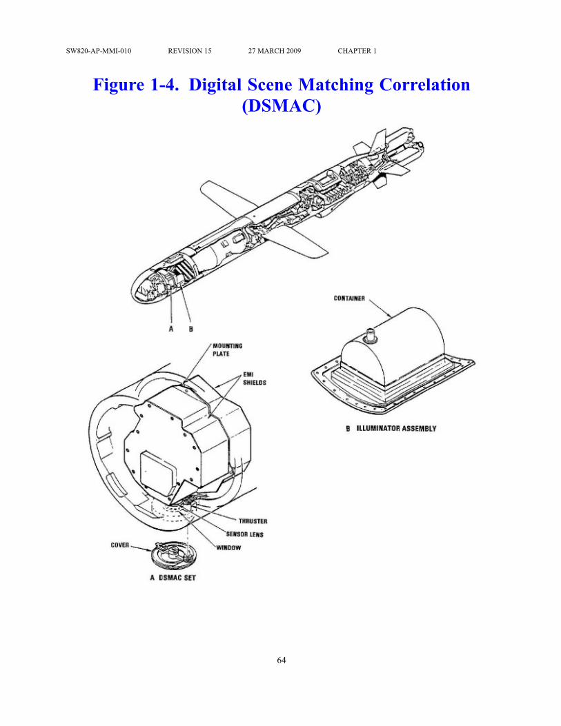
SW820-AP-MMI-010 REVISION 15 27 MARCH 2009 CHAPTER 1
Figure 1-4. Digital Scene Matching Correlation(DSMAC)
64

SW820-AP-MMI-010 REVISION 15 27 MARCH 2009 CHAPTER 1
Figure 1-5. Land-Attack 109D
65

SW820-AP-MMI-010 REVISION 15 27 MARCH 2009 CHAPTER 1
Figure 1-6. Land-Attack 109D Payload Section
66

SW820-AP-MMI-010 REVISION 15 27 MARCH 2009 CHAPTER 1
Figure 1-7. Block IV Tactical TOMAHAWK MissileGeneral Arrangement
67

SW820-AP-MMI-010 REVISION 15 27 MARCH 2009 CHAPTER 1
Figure 1-8. TACTOM Forward Body Section
68

SW820-AP-MMI-010 REVISION 15 27 MARCH 2009 CHAPTER 1
Figure 1-9. Mk 106 Rocket Motor
69

SW820-AP-MMI-010 REVISION 15 27 MARCH 2009 CHAPTER 1
Figure 1-10. Mk 111 Rocket Motor
70

SW820-AP-MMI-010 REVISION 15 27 MARCH 2009 CHAPTER 1
Figure 1-11. Underwater Protection Devices
71
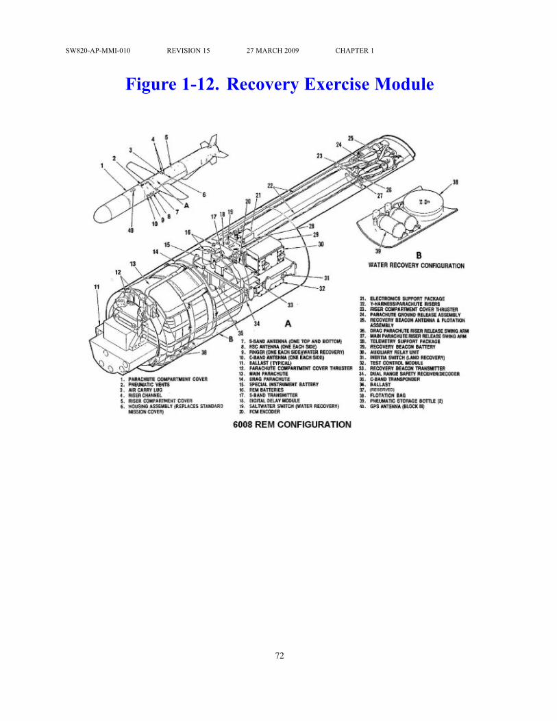
SW820-AP-MMI-010 REVISION 15 27 MARCH 2009 CHAPTER 1
Figure 1-12. Recovery Exercise Module
72

SW820-AP-MMI-010 REVISION 15 27 MARCH 2009 CHAPTER 1
Figure 1-13. TACTOM Midbody Section
73

SW820-AP-MMI-010 REVISION 15 27 MARCH 2009 CHAPTER 1
Figure 1-14. Range Safety System (109C)
74

SW820-AP-MMI-010 REVISION 15 27 MARCH 2009 CHAPTER 1
Figure 1-15. Range Safety System (109D)
75

SW820-AP-MMI-010 REVISION 15 27 MARCH 2009 CHAPTER 1
Figure 1-16. Typical Land-Attack TCM Pre-landfallFlyout Route
76

SW820-AP-MMI-010 REVISION 15 27 MARCH 2009 CHAPTER 1
Figure 1-17. Terrain Contour Matching (TERCOM)Process
77

SW820-AP-MMI-010 REVISION 15 27 MARCH 2009 CHAPTER 1
Figure 1-18. TACTOM Aftbody and Tailcone Section
78

SW820-AP-MMI-010 REVISION 15 27 MARCH 2009 CHAPTER 1
Figure 1-19. Typical Mission Profile (109A/C)
79

SW820-AP-MMI-010 REVISION 15 27 MARCH 2009 CHAPTER 1
Figure 1-20. Typical Mission Profile (109D)
80

SW820-AP-MMI-010 REVISION 15 27 MARCH 2009 CHAPTER 1
Figure 1-21. CLS Missile Tube Loading and HandlingTrainer Assembly
81

SW820-AP-MMI-010 REVISION 15 27 MARCH 2009 CHAPTER 1
Figure 1-22. Typical Parachute Recovery ofREM-Equipped Missile
82

SW820-AP-MMI-010 REVISION 15 27 MARCH 2009 CHAPTER 1
Figure 1-23. TTL Capsules (2 Sheets)
83

SW820-AP-MMI-010 REVISION 15 27 MARCH 2009 CHAPTER 1
84

SW820-AP-MMI-010 REVISION 15 27 MARCH 2009 CHAPTER 1
Figure 1-24. Electrical and Pneumatic Umbilicals
85

SW820-AP-MMI-010 REVISION 15 27 MARCH 2009 CHAPTER 1
Figure 1-25. CNU-308/E Shipping Container
86

SW820-AP-MMI-010 REVISION 15 27 MARCH 2009 CHAPTER 1
Figure 1-26. Capsule Launching System (CLS) Mk 45
87

SW820-AP-MMI-010 REVISION 15 27 MARCH 2009 CHAPTER 1
Figure 1-27. Capsule Launching System (CLS)Components
88

SW820-AP-MMI-010 REVISION 15 27 MARCH 2009 CHAPTER 1
Figure 1-28. All-Up-Round Simulator (AURS)Volumetric Shape
89

SW820-AP-MMI-010 REVISION 15 27 MARCH 2009 CHAPTER 1
Figure 1-29. All-Up-Round Electronic Simulator(AURES) Mk 101
90

SW820-AP-MMI-010 REVISION 15 27 MARCH 2009 CHAPTER 1
Figure 1-30. AURES/AURS Interface
91

SW820-AP-MMI-010 REVISION 15 27 MARCH 2009 CHAPTER 1
Figure 1-31. Missile Tube Ballast Can
92

SW820-AP-MMI-010 REVISION 15 27 MARCH 2009 CHAPTER 1
Figure 1-32. Shipping and Storage Skid Mk 30
93

SW820-AP-MMI-010 REVISION 15 27 MARCH 2009 CHAPTER 1
Figure 1-33. AUR Simulator Shipping Skid
94

SW820-AP-MMI-010 REVISION 15 27 MARCH 2009 CHAPTER 1
Figure 1-34. Mk 10 Canister
95

SW820-AP-MMI-010 REVISION 15 27 MARCH 2009 CHAPTER 1
Figure 1-35. Mk 14 Canister (2 Sheets)
96

SW820-AP-MMI-010 REVISION 15 27 MARCH 2009 CHAPTER 1
97

SW820-AP-MMI-010 REVISION 15 27 MARCH 2009 CHAPTER 1
Figure 1-36. Shipping and Storage Skid Mk 34
98

SW820-AP-MMI-010 REVISION 15 27 MARCH 2009 CHAPTER 1
Figure 1-37. CLS Submarine Missile Tube TrainerAssembly
99

SW820-AP-MMI-010 REVISION 15 27 MARCH 2009 CHAPTER 1
Figure 1-38. SMTT Training Shape
100

SW820-AP-MMI-010 REVISION 15 27 MARCH 2009 CHAPTER 1
Figure 1-39. CLS Mk 45 Mod 2 Aft Cover
101

SW820-AP-MMI-010 REVISION 15 27 MARCH 2009 CHAPTER 1
Figure 1-40. CLS Mk 45 Mod 2 Capsule ClosureAssembly
102

SW820-AP-MMI-010 REVISION 15 27 MARCH 2009 CHAPTER 1
Figure 1-41. SSGN (Prototype) Multiple All-Up-RoundCanister (MAC)
103

SW820-AP-MMI-010 REVISION 15 27 MARCH 2009 CHAPTER 1
Table 1-1. Support Equipment DescriptionEQUIPMENT FUNCTION ILLUSTRATION
Adapter Box AssyP/N JCM-17683
Used with Rocket Motor/Ident Test SetBox Assembly for performing CLSmissile electrical checks.
Adapter, CapsulePneumatic
P/N 7324001-01
Interface between TTLCapsule/TOTEM Capsule pneumaticcoupling and pressurization equipment.
Adapter, Endlift,Container Mk 156 Mod 0
P/N 5166882
Handle CNU-308/E Shipping Containerwith pallet truck.
Adapter, Hook Mk 91Mod 0
P/N 2643315
Use with forklift and sling to handleuncontainerized TTL and Mk 10weapons.
Adapter, Hook Mk 176Mod 0
P/N 6213621
Use with forklift and sling to handleuncontainerized CLS weapons.
Adapter, Missile RoundPneumatic Test
P/N 6242918-1
Perform VLS weapon pressure checkand pressure service.
104

SW820-AP-MMI-010 REVISION 15 27 MARCH 2009 CHAPTER 1
EQUIPMENT FUNCTION ILLUSTRATIONAdapter, Support Cradle,Forward Mk 168 Mod 0
P/N 5917395
Supports forward end of CLS weaponwhen connected to the Mk 26Uprighting Fixture.
Adapter, Trunnion BearingAssembly Mk 174 Mod 0
P/N JCM-17863
Attaches to CLS weapon to act as pivotto permit transitioning between verticaland horizontal during onload/off-load.
Alignment Guide, NoseCover Attachment
P/N 76Z7894-1
Aligns nose cover/capsule screw holesto attach nose cover to Capsule Mk 1Mod 0/TOTEM Capsule.
Alignment Guide, NoseCover Attachment
P/N 76Z7897-3
Aligns nose cover/capsule screw holesto attach nose cover to Capsule Mk 3Mod 0/TOTEM Capsule.
Alignment Tool, GuidanceSet
P/N 6145719
Maintain control of the Cruise MissileGuidance Set during 109A warheadingand dewarheading.
Assembly, Chain andAdjuster
P/N MB-1/CGU-4E
Secure weapons and containers in smallboats.
105

SW820-AP-MMI-010 REVISION 15 27 MARCH 2009 CHAPTER 1
EQUIPMENT FUNCTION ILLUSTRATIONAssembly, ProtectiveSleeve, O-ring
P/N 101-5951066/4/5/50/6(SSN 688)
P/N 7066384-71(SSN 774)
Protect O-rings on CLS weapon.
Band, CLS,TOMAHAWK, Mk 90Mod 0
P/N 5167268
Used with Taglines Mk 4 Mod 0 tomaintain control of uncontainerizedCLS weapons.
Band, Mk 87 Mod 0P/N 5166711
Used with Taglines Mk 3 Mod 0 tomaintain control of uncontainerizedTTL and Mk 10 weapons.
Beam, Hoisting, AURContainer Mk 46 Mod 0
P/N 5167804
Handle containerized TTL and Mk 10weapons.
Beam, Lifting, MK 44,Mod 0
P/N 5167164
Handle uncontainerized TTL and Mk10 weapons.
Cable Adapter UmbilicalAssy
P/N 3193140-028-101
Used with Rocket Motor/Ident Test SetBox Assembly for performing TTLmissile electrical checks.
Cable Adapter UmbilicalAssy
P/N 3193140-028-102(ConventionalUse Only)
Used with Rocket Motor/Ident Test SetBox Assembly for performing TTLmissile electrical checks.
106

SW820-AP-MMI-010 REVISION 15 27 MARCH 2009 CHAPTER 1
EQUIPMENT FUNCTION ILLUSTRATIONCable Assy
P/N 3193140-013-101
Used with Rocket Motor/Ident Test SetBox Assembly for performing missileelectrical checks.
Canister Loader, VLS, Mk33 Mod 0
P/N 5167196
Encanister/decanister VLS weapons
Cap, Faraday, UpperUmbilical Connector
P/N JCM-14339-001
Provides electrical shielding for theelectrical umbilical connector on CLSAUR and CLS Loading and HandlingTraining Shape.
Container, ClosureShipping
P/N JCM-14843-002
Protects the CLS AUR and CLSLoading and Handling Training ShapeCapsule Closure Assembly duringtransport and handling.
Cover Assy, Shock PlateP/N 7124611-002
Used to cover the AUR bore holes inthe middle and lower shock plates.Provides a flat, non-skid surfacewithout raised handles and will preventitems from falling into the MAC cell.
Cover Assy, Top HatP/N 7124611-004
Placed over loaded AURs to protectthem from damage after the CLChas been removed, during the AURclose-out procedure, or in the event thatan AUR has to be pulled and replaced.Provides a level surface strong enoughfor a worker to stand on.
Cover Assy, Top PlateP/N 7124611-003
Used to cover the MAC AUR cellsand to provide a flat, non-skid surfacewithout raised handles. It preventsitems from falling into the MAC cell.
107
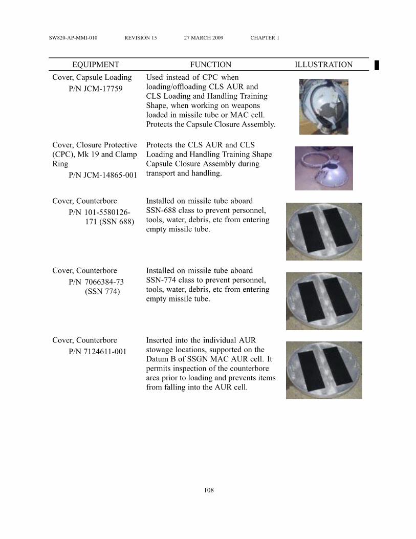
SW820-AP-MMI-010 REVISION 15 27 MARCH 2009 CHAPTER 1
EQUIPMENT FUNCTION ILLUSTRATIONCover, Capsule Loading
P/N JCM-17759Used instead of CPC whenloading/offloading CLS AUR andCLS Loading and Handling TrainingShape, when working on weaponsloaded in missile tube or MAC cell.Protects the Capsule Closure Assembly.
Cover, Closure Protective(CPC), Mk 19 and ClampRing
P/N JCM-14865-001
Protects the CLS AUR and CLSLoading and Handling Training ShapeCapsule Closure Assembly duringtransport and handling.
Cover, CounterboreP/N 101-5580126-
171 (SSN 688)
Installed on missile tube aboardSSN-688 class to prevent personnel,tools, water, debris, etc from enteringempty missile tube.
Cover, CounterboreP/N 7066384-73
(SSN 774)
Installed on missile tube aboardSSN-774 class to prevent personnel,tools, water, debris, etc from enteringempty missile tube.
Cover, CounterboreP/N 7124611-001
Inserted into the individual AURstowage locations, supported on theDatum B of SSGN MAC AUR cell. Itpermits inspection of the counterborearea prior to loading and prevents itemsfrom falling into the AUR cell.
108

SW820-AP-MMI-010 REVISION 15 27 MARCH 2009 CHAPTER 1
EQUIPMENT FUNCTION ILLUSTRATIONCover, Missile TubeMuzzle Hatch and MagnetProtective
P/N 101-5951066-54(SSN 688)
Cover, Missile TubeMuzzle Hatch and SwitchProbe Protective
P/N 7066384-72(SSN 774)
Protect muzzle hatch magnets in hatchopening of submarine.
Cover, Muzzle FaceProtective
P/N 101-5951066-49
Used to prevent damage to muzzlehatch gasket sealing surface in missiletube.
Cover, Safety MTELP/N JCM-14566-001
Installed on MTEL prior to CLSweapon onload/after offload. ProtectsMTEL, missile tube, and MAC cell(SSGN).
Cover, VLS Missile Tube,CLS Spent Capsule
P/N 6510965
Installed over spent CLS to preventpersonnel, tools, debris, etc fromentering spent capsule.
Cradle Mk 33 Mod 0P/N 6213118
Secure and transport TTL and Mk 10weapons by truck and small boat.
109

SW820-AP-MMI-010 REVISION 15 27 MARCH 2009 CHAPTER 1
EQUIPMENT FUNCTION ILLUSTRATIONCradle Mk 34 Mod 0
P/N 6213249Secure and transport CLS weapons bysmall boat.
Cradle, UnderseaWeapons TransportingMk 27 Mod 0
P/N 5165994
Transfer weapons on small boats.
Device, Tie-downP/N CGU-1/B
Secure weapons and containers in smallboats.
Dolly Assembly, MissileHandling Mk 34 Mod 0
P/N 5167224
Transport Mk 30 Shipping and StorageSkid.
Dolly, VLS Transport Mk35 Mod 0
P/N 5167396
Transport Mk 14 Canister
Fixture, CLS CapsuleUprighting Mk 26 Mod 0
P/N 5917401or Mk 26 Mod 1
P/N 6213396
Transition CLS weapons betweenvertical and horizontal during onloadand off-load.
Fixture, MissilePositioning MTU-68/E
P/N 76Z3550-30
Move the missile about nine inchesout of/into the capsule duringUGM-109A-1 warheading anddewarheading.
110

SW820-AP-MMI-010 REVISION 15 27 MARCH 2009 CHAPTER 1
EQUIPMENT FUNCTION ILLUSTRATIONFixture, Tilt Mk 23 Mod 0
P/N 5167473With Kit A, transition Mk 14 Canisterbetween the horizontal and verticalpositions. With Kit B, transition CLSweapon between vertical and horizontalfor onload and offload.
Gauge, Load ButtonP/N 7339399/No
NSN
Verify any TTL capsule load buttonis not oversized, bent or otherwisedistorted so as to cause problems duringtube loading aboard a submarine
Hoist, Chain, Hand, 2-ton,15-ft Lift
P/N LHH-2B-15
Used with Hoisting Sling Mk 157 tochange position of lifting adapter orMTEL.
Hydraulic Power Unit(HPU) Mk 8 Mod 0
P/N JCM-14899-001
With MTEL, provides insertion andextraction force to seat/unseat CLSweapons (except ballast can) into/out ofthe missile tube/MAC cell.
Installation Guide Mk 116Mod 0
P/N JCM-14375-001
Align MTEL to prevent missile tubedamage during MTEL installation andremoval.
Kit, Pressure ServicingMk 182 Mod 0
P/N 5759440
Pressurize TTL and Mk 10 weapons
Kit, Pressure Servicing,CLS Forward Mk 184Mod 0
P/N 6199900
Pressurize CLS AUR and CLS Loadingand Handling Training Shape forwardsection.
Consists of:
111

SW820-AP-MMI-010 REVISION 15 27 MARCH 2009 CHAPTER 1
EQUIPMENT FUNCTION ILLUSTRATIONClosure Pressure HosePneumatic Adapter
P/N 6146684
CPC Pneumatic AdapterP/N 6199896
Pressurizing Gear TesterT3159
P/N 5545882
CLS Pressurizing HoseAssembly, FWD
P/N 6146623
Lifting Adapter AssemblyMk 169 Mod 0
P/N JCM-14699-001
Attaches to CLS weapon (exceptballast can) to upright, lift or lowerCLS weapon during submarineonload/off-load.
Missile TubeExtension/Loader(MTEL) Mk 23 Mod1
P/N JCM-14455-002
Aligns, and with HPU, inserts/extractsCLS weapon (except ballast can)into/out of missile tube/MAC cell.
Multi-Test Box Mk 71Mod 0
P/N 6574418
Verify electrical continuity and isolationof specific wires in the pyro harness.
112

SW820-AP-MMI-010 REVISION 15 27 MARCH 2009 CHAPTER 1
EQUIPMENT FUNCTION ILLUSTRATIONPin, Trunnion
P/N 5768606Alternate to Mk 174 Trunnion BearingAdapter to transition the All-Up-RoundSimulator and CLS Ballast Canbetween vertical and horizontal duringonload/off-load.
Platform, LoadingP/N 5580126
Used on SSN 688 Class submarines foraccess to missile tubes.
Platform, LoadingP/N 7066384-A1
Used on SSN 774 Class submarines foraccess to missile tubes.
Platform, MTEL WorkP/N 7126403-002
Allows access to the area abovethe MTEL during SSGN handlingoperations.
Plug Assembly, Moistureand Dust
JCM-17838/4730-01-346-3387
Seals pressure/vent port on CLS AUR,AUR Simulator and CLS Loading andHandling Trainer.
Pressure VacuumDistributor H3353
P/N 5758382
Purge and backfill warhead cavity andmissile during 109A warheading anddewarheading.
113

SW820-AP-MMI-010 REVISION 15 27 MARCH 2009 CHAPTER 1
EQUIPMENT FUNCTION ILLUSTRATIONProtective Shield,Umbilical Cable
P/N JCM-17873
Installed on the CLS AUR and CLSLoading and Handling Training Shapeumbilical cable during off-load toprevent damage from contact withthe missile tube while extracting theweapon from the tube. Not requiredwith new design umbilical cablewith angled cable flange penetratorovermold.
Pump, Submersible, 440Volt with Foot ValveAssembly
Remove ballast from CLS ballast can.
Retainer, Separation NutLockring Wrench
P/N 76L5319-1
Prevent Mk 10 separation nut lockringwrench from backing out of lockringand rounding holes.
Security Band AssemblyP/N 5979383
Attaches over nose coverof UGM-109A-1 to preventunauthorized/inadvertent tube loadaboard the submarine.
Security Cover 4FZP/N 76A2994-1
Replaces electrical connector protectivecover on UGM-109A-1 aboardsubmarine to allow connection of 4FZsecurity system.
114

SW820-AP-MMI-010 REVISION 15 27 MARCH 2009 CHAPTER 1
EQUIPMENT FUNCTION ILLUSTRATIONSling, Hoisting, ContainerHLU-265/E
P/N 76Z3525-16or Mk 152 Mod 0
P/N 5167256
Handle CNU-308/E ShippingContainer.
Sling, Lifting Mk 95 Mod0
P/N 2642629
Handle uncontainerized TTL and Mk10 weapons.
Sling, Lifting Mk 114Mod 0
P/N 2643810
Handle uncontainerized TTL and Mk10 weapons in areas where clearancedoes not allow use of Mk 95 Sling.
Sling, Lifting Mk 162Mod 0
P/N 1001-6212682
Connect lifting apparatus and liftingdevice. Shall not be used to handleCLS AUR and AURS.
Sling, Lifting AssemblyP/N 5580126-271
(SSN 688)P/N 7066384-A14
(SSN 774)
Handle CLS loading platform.
Sling, Lifting AssemblyP/N 6510856 (SSN
688)P/N 7066384-A13
(SSN 774)
Used to lift ballast can.
115

SW820-AP-MMI-010 REVISION 15 27 MARCH 2009 CHAPTER 1
EQUIPMENT FUNCTION ILLUSTRATIONSling, Lifting, AUR, Mk154 Mod 0
P/N 5167321
Handle uncontainerized CLS weapons.
Sling, Lifting, AURSimulator Shipping SkidCover
P/N 5951067
Remove/install AUR SimulatorShipping Skid covers.
Sling, Lifting, AURSimulator Shipping Skid
P/N 6510902
Handle AUR Simulator Shipping Skid
Sling, Lifting and Tilting(Lifting Adapter/MTEL)Mk 157 Mod 1
P/N JCM-14748-002
Transition the Lifting Adapter andMTEL between vertical and horizontal.
Sling, Pendant Mk 165Mod 0
P/N 6213009or Mk 165 Mod 1
P/N 6213750
Interface between lifting device andload.
Sling, Weapon, HandlingMk 153 Mod 0
P/N 5167582
Handle Mk 30 AUR Shipping andStorage Skid or Mk 34 AUR SimulatorShipping and Storage Skid
116

SW820-AP-MMI-010 REVISION 15 27 MARCH 2009 CHAPTER 1
EQUIPMENT FUNCTION ILLUSTRATIONSocket, Special, 3/8-inch
P/N JCM-16654Remove/install Moisture and Dust PlugAssembly.
Special Hose AssemblyP/N 6309846
Perform Mk 14 Canister nitrogen lineleak check.
Consists of:Regulator Hose Assembly
P/N 6309846-1
Digital Pressure GageHose Assembly
P/N 6309846-2/ SetraModel 360
Pneumatic Test AdapterP/N 6309846-3
Rocket Motor/Ident TestSet, Box Assy
6557811
Used when performing missileelectrical checks.
Stand, DeploymentP/N 6510854
Used to support sections of SSN 688Class loading platform.
Stand, DeploymentP/N 7066384-A3
Used to support sections of SSN 774Class loading platform.
117

SW820-AP-MMI-010 REVISION 15 27 MARCH 2009 CHAPTER 1
EQUIPMENT FUNCTION ILLUSTRATIONStraps, Tie-down, SpecialPurpose
P/N CBU
Secure weapons and containers in smallboats.
Strongback, Horizontal,VLS Mk 3 Mod 0
P/N 5598249-9
Handle Mk 14 Mod 1 Canister
Strongback, Horizontal,VLS Mk 3 Mod 1
P/N 72511117-9
Handle Mk 14 Mod 1 or Mod 2 Canister
Strongback, Vertical, VLSMk 4 Mod 0
P/N 5497606
Onload/off-load Mk 14 Canister
Support System Mk 8Mod 0
P/N 6213373
Support TTL and Mk 10 weapons instorage.
Tagline, Mk 3 Mod 0P/N 5166715
or Mk 4 Mod 0P/N 5166702
With Mk 87/Mk 90 Band, maintaincontrol of uncontainerized weaponsduring handling. Maintain control ofcontainers during handling.
118

SW820-AP-MMI-010 REVISION 15 27 MARCH 2009 CHAPTER 1
EQUIPMENT FUNCTION ILLUSTRATIONTester, Igniter,Amptec Model630AN/630BN/641N
Used for testing the igniters in solidfuel rocket engines, detonation circuitsin warheads, explosive separation boltsor any other squib actuated devices.
Threadsaver, TrunnionBearing
P/N JCM-17679
Used in place of trunnion bearingassemblies to preserve threads intrunnion bearing holes.
Tool Kit, Nose DiaphragmP/N 76Z0667-1
Remove/install nose diaphragmduring UGM-109A-1 warheading anddewarheading.
Tool Kit, Special WeaponsP/N 76Z6333-8
Set of four tools to: alignmissile/capsule; detach/attach holdbacknuts; protect holdback assembly; andremove/install booster lanyard nutduring UGM-109A-1 warheading anddewarheading.
Tool, Lip SealP/N JCM-17678
Used to install lip seals.
Trailer, Munitions Aero51 B/C/D
P/N 67A314F100
Transport containerized anduncontainerized weapons.
119

SW820-AP-MMI-010 REVISION 15 27 MARCH 2009 CHAPTER 1
EQUIPMENT FUNCTION ILLUSTRATIONTruck, Handlift Mk 45Mod 2
P/N 5167104
Handle CNU-308/E Shipping Container
Truck, Pallet, Low Lift Handle CNU-308/E Shipping Container
TrunnionP/N JCM-14514-001
Used when lowering the CLS AURinto the Mk 23 Tilt Fixture. Can also beused for uprighting the All-Up-RoundSimulator and Ballast Can.
Umbilical Breakout Box(UBOB) Mk 674 Mod 1
P/N 7379010
Perform VLS weapon electrical tests.
Universal Restraint StandMk 121 Mod 0
P/N 6146521
Warhead 109A. May be used formaintenance on TTL, Mk 10 and VLSweapons
Vertical Launch System(VLS) Canister Code PlugTest Set Mk 673 Mod 0
P/N 6375451
Determine VLS canister code plugconfiguration.
Weapons Skid Aero 21CP/N 64A114H1-4
or Munitions TransporterMHU-191-M
P/N 1500AS100-1
With Mk 130 Mod 0 Extension Handle,Aero 64A/64B Soft Belt Adaptersand front and rear Aero 58A/58BSkid Adapters installed, transportuncontainerized TTL and Mk 10weapons.
120

SW820-AP-MMI-010 REVISION 15 27 MARCH 2009 CHAPTER 1
EQUIPMENT FUNCTION ILLUSTRATIONWrench, CanisterSeparation Nut Lockring
P/N 76Z4738-1
Loosen and tighten separation nutlockring duringMk 10 encanisterizationand decanisterization.
Wrench, SpannerP/N JCM-17635
Tighten CLS AUR and CLS Loadingand Handling Training Shape umbilicalcable connector P130B
Wrench, CanisterSeparation Nut Lockring
P/N 76Z4738-1
Loosen and tighten separation nutlockring duringMk 10 encanisterizationand decanisterization.
Wrench, SpannerP/N JCM-17635
Tighten CLS AUR and CLS Loadingand Handling Training Shape umbilicalcable connector P130B
121

SW820-AP-MMI-010 REVISION 15 27 MARCH 2009 CHAPTER 1
EQUIPMENT FUNCTION ILLUSTRATIONWrench, Spanner
P/N 76M0235-1Remove/install positive retention nosecone during 109A warheading anddewarheading.
Wrench, Spanner, NoseCoupler KMU-467/E
P/N 76Z3553-8
Remove/install positive retention nosecone during 109A warheading anddewarheading.
122

SW820-AP-MMI-010 REVISION 15 27 MARCH 2009 CHAPTER 1
Table 1-2. Shipboard Equipment Used forTOMAHAWK Support
EQUIPMENT FUNCTION ILLUSTRATIONAdapter, Dolly
P/N SK5711-735Adapt tender stowage rack dollies tosupport TTL weapons.
Chocks, Portable(Stowage Rack)
P/N SK5111-738
Adapt stowage rack for TTL stowageon board AS- 39 Class submarinetenders.
Decking, Small Boat(LCM Mk 6)
Provide a platform to secure weaponsin LCM Mk 6. Consists of four decksections secured together with ironbolts and angle irons.
Dolly, Stowage Rack Stow TTL weapons on AS-39 ClassSubmarine Tenders. A telescoping tugbar is used with the dolly. All dolliesare modified with the Adapter, Dolly,P/N SK5711-735.
Plenum Cell CoverAssembly
Seals the bottom of a launcher cellto permit launch gases to be ventedthrough the uptake into the atmosphere
Sill Assembly Seal the Mk 14 Canister in the launchcell to divert launch gases to theatmosphere via the plenum cell.
123

SW820-AP-MMI-010 REVISION 15 27 MARCH 2009 CHAPTER 1
Table 1-3. Reference DocumentationDOCUMENT NUMBER TITLE
Record Book All-Up-Round (AUR) Volumetric ShapeRecord Book Missile Tube Ballast Can (MTBC)
0348-LP-078-1000 Technical Manual for Magazine Sprinkler System0924-LP-066-6010/-6020 Electrically Suspended Gyro Navigator (ESGN)
AN/WSN-3A(V)2
0967-LP-529-6010 Dual Miniature Inertial Navigation System (DMINS)AN/WSN-1(V)2
0978-LP-040-0910 Weapon Delivery Systems Equipments Manual for SSN688 Class Submarines
ASME/ANSI B30.5-1989 Safety Standards for Mobile and Locomotive Cranes
ASME/ANSI B30.8-1988 Safety Standards for Floating Cranes and FloatingDevices
CINCLANTFLTINST 8010.4 Atlantic Fleet Conventional Ordnance ManagementManual
CINCPACFLTINST 8010.12 Pacific Fleet Ammunition Requisitioning and ReportingGuide
CMP PUB 4440/2 Record Book for TOMAHAWK Test Missile (TOTEM)CMP PUB PMA 280-1203 User’s Logistics Support Summary (ULSS) for the
TOMAHAWK Cruise Missile UGM-109-1 andTOMAHAWK Cruise Missile UGM-109-2
CMP PUB PMA 280-1207 Integrated Logistics Support Plan (ILSP) for SeaLaunched Cruise Missile (SLCM) TOMAHAWKAll-Up-Round
CMP PUB ULSS 4105-D Advanced TOMAHAWK Weapon Control SystemAN/SWG-4(V) Launch Control Group Replacement(TL4 Configuration)
CMP PUB ULSS PMA 280-1205 VLS Mk 14 Canisters with TOMAHAWK CruiseMissiles at Intermediate Maintenance Activities andLimited Maintenance Activities
CMPINST 5102.1 Explosive Mishap Reporting ProceduresCode of Federal Regulations Title46
Shipping
124

SW820-AP-MMI-010 REVISION 15 27 MARCH 2009 CHAPTER 1
DOCUMENT NUMBER TITLECode of Federal Regulations Title49
Transportation
DOD Regulation 4500.32-R Defense Transportation System, Policies and ProceduresDOD-STD-1686 Electrostatic Discharge Control Program for Protection
of Electrical and Electronic Parts, Assemblies andEquipment (Excluding Electrically Initiated ExplosiveDevices)
ILSP-167 P/D Integrated Logistics Support Plan (ILSP) for VerticalLaunching System Mk 41
JCS PUB 6 VOL II Part 4 Joint Reporting Structure (JRS) Volume II, Joint Reports,Part 4, Nuclear Weapons (NUREP)
MD 4790.100/.200 Shore Activity Maintenance Data Collection SystemMD 55658 Checkout Procedures and Inspection Requirements for
Vertical Launching System Umbilical Breakout Box Mk674 Mod 0
MD 56068 User’s Manual for VLS Canister Code Plug Test Set Mk673 Mod 0
MIL-STD-129 Marking for Shipment and StorageMIL-STD-1320-235 Truckloading Encapsulated TOTEM, TOTEM Capsule
and Expended CapsuleMIL-STD-1320-246 Truckloading CLS Ballast Cans ChockedMIL-STD-1320-264 Truckloading VLS Canisters Mk 13, 14 & 15 and All
Mods and Mixed Loads "Empty and w/o PHS&T"MIL-STD-1949 Military Standard Inspection Magnetic ParticleMIL-STD-2000 Standard Requirements for Soldered Electrical and
Electronic AssembliesMIL-STD-410 Nondestructive Testing Personnel Qualification and
CertificationMIL-STD-6866 Military Standard Inspection Liquid PenetrantNAVAIR 19-15BC-13 Operations and I-Level Maintenance Instructions with
Illustrated Parts Breakdown, Weapons Skid Aero 21C;Part Number 64A114H-4
NAVSEA Dwg. 6213981 Truckload Guided Missile U/RGM-109 (TOMAHAWK)in Shipping and Storage Container CNU- 308/E
125

SW820-AP-MMI-010 REVISION 15 27 MARCH 2009 CHAPTER 1
DOCUMENT NUMBER TITLENAVSEA Dwg. 6213982 Truckload Guided Missile UGM-109-2 (TOMAHAWK-
CLS) in Shipping and Storage Skid Mk 30 Mods 0, 1and 2
NAVSEA Dwg. 6213983 Truckload Guided Missile RGM-109 (TOMAHAWK) inVLS Canister Mk 14 Mods 0 and 1
NAVSEA Dwg. 6213987 Truckload, Guided Missile RGM-109 (TOMAHAWK) inVLS Canister MK 14 Mods 0 and 1 and Guided MissileU/RGM-109 (TOMAHAWK) in Container CNU-308/E
NAVSEA Dwg. 6214071 ISO Container Load, Shipping and Storage Skid Mk 30Mods (TOMAHAWK) in 40 Ft Full Height Open TopISO Container
NAVSEA OD 44979 Firing Craft Operating Procedures and ChecklistsNAVSEA OD 46574 Weapon and Combat Systems Quality Assurance
Requirements for Shore Stations and Engineering AgentsNAVSEA OD 48845 Metrology Requirements ListNAVSEA OD 48854 Field Calibration Activity Metrology Requirements ListNAVSEA OP 2239 Explosive Driver’s HandbookNAVSEA OP 3206 Handling and Stowage of Naval Ordnance Aboard
Ammunition ShipsNAVSEA OP 3221 Loading and Stowage of Military Explosives Aboard
Breakbulk Merchant ShipsNAVSEA OP 3347 United States Navy Ordnance Safety PrecautionsNAVSEA OP 3565 Radio Frequency Hazards to Ordnance, Personnel and
FuelNAVSEA OP 4 Ammunition AfloatNAVSEA OP 5, Vol I Ammunition and Explosives Ashore Regulations for
Handling, Storing, Production Renovation and ShippingNAVSEA OR 99 Series Intermediate and Depot Maintenance Instructions for
(Specified Handling and Support Equipment)NAVSEAINST 5511.28 Guided Missiles: Security Classification GuideNAVSEAINST 8020.9 Non-Nuclear Ordnance and Explosive Handling
Qualification and Certification ProgramNAVSEAINST 8020.13 Emergency Response Procedures for Transportation
Accidents
126

SW820-AP-MMI-010 REVISION 15 27 MARCH 2009 CHAPTER 1
DOCUMENT NUMBER TITLENAVSEAINST 8023.2 US Navy Explosive Safety Policies, Requirements and
Procedures (Department of Navy Explosive Safety PolicyManual)
NAVSEAINST 4855.7 Reporting of Unsatisfactory MaterialNAVSUP PUB 409 MILSTRIP/MILSTRAP Desk GuideNAVSUP PUB 437 Military Standard Requisitioning and Issue Procedures
(MILSTRIP)NAVSUP PUB 4500 Consolidated Hazardous Items List (CHIL)NAVSUP PUB 485 Afloat Supply ProceduresNAVSUP PUB 505 Preparing Hazardous Materials for Air ShipmentNAVSUPINST 4400.189 Reporting of Non-Conforming and Quality Deficient
Material Obtained Through the Supply SystemsNAVSUPINST 4423.14 Navy Uniform Source, Maintenance and Recoverability
CodesNAVSUPINST 4440.120 Disposition of Used or Damaged MaterialNAVSUPINST 4600.70 Military Traffic Management RegulationsNSPCCINST P8010.12 Supply Management of AmmunitionNTP-A-20-7703 Navy Training Plan (NTP) UGM-109 TOMAHAWK
Cruise Missile Submarine Torpedo Tube Launch (TTL)and SSN 688 Class Vertical Launch System (VLS)Capsule Launching System (CLS)
OD 44979 Firing Craft Operating Procedures and Checklists forWeapon Loading and Handling Systems SSN 774 Class
OPNAVINST 4790.4 Ships’ Maintenance and Material Management (3M)Manual
OPNAVINST 5102.1 Mishap Investigation and ReportingOPNAVINST 5510.1 Department of Navy Information and Personnel Security
Program RegulationOPNAVINST 5530.13 Physical Security Instructions for Sensitive Conventional
Arms, Ammunition and Explosives (A A&E)OPNAVINST C8126.1/DODC-5210.41M
Nuclear Weapons Security Manual
OPNAVINST S5513.2 Cruise Missile Classification Guide
127
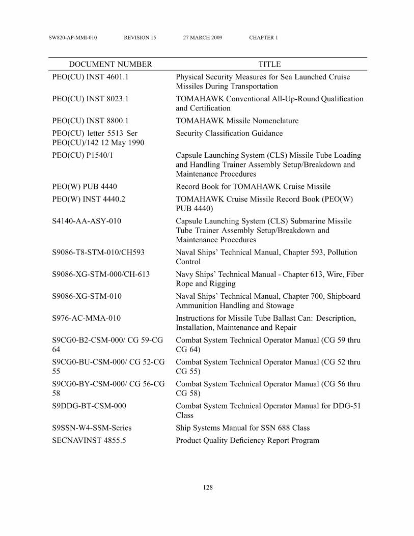
SW820-AP-MMI-010 REVISION 15 27 MARCH 2009 CHAPTER 1
DOCUMENT NUMBER TITLEPEO(CU) INST 4601.1 Physical Security Measures for Sea Launched Cruise
Missiles During TransportationPEO(CU) INST 8023.1 TOMAHAWK Conventional All-Up-Round Qualification
and CertificationPEO(CU) INST 8800.1 TOMAHAWK Missile NomenclaturePEO(CU) letter 5513 SerPEO(CU)/142 12 May 1990
Security Classification Guidance
PEO(CU) P1540/1 Capsule Launching System (CLS) Missile Tube Loadingand Handling Trainer Assembly Setup/Breakdown andMaintenance Procedures
PEO(W) PUB 4440 Record Book for TOMAHAWK Cruise MissilePEO(W) INST 4440.2 TOMAHAWK Cruise Missile Record Book (PEO(W)
PUB 4440)S4140-AA-ASY-010 Capsule Launching System (CLS) Submarine Missile
Tube Trainer Assembly Setup/Breakdown andMaintenance Procedures
S9086-T8-STM-010/CH593 Naval Ships’ Technical Manual, Chapter 593, PollutionControl
S9086-XG-STM-000/CH-613 Navy Ships’ Technical Manual - Chapter 613, Wire, FiberRope and Rigging
S9086-XG-STM-010 Naval Ships’ Technical Manual, Chapter 700, ShipboardAmmunition Handling and Stowage
S976-AC-MMA-010 Instructions for Missile Tube Ballast Can: Description,Installation, Maintenance and Repair
S9CG0-B2-CSM-000/ CG 59-CG64
Combat System Technical Operator Manual (CG 59 thruCG 64)
S9CG0-BU-CSM-000/ CG 52-CG55
Combat System Technical Operator Manual (CG 52 thruCG 55)
S9CG0-BY-CSM-000/ CG 56-CG58
Combat System Technical Operator Manual (CG 56 thruCG 58)
S9DDG-BT-CSM-000 Combat System Technical Operator Manual for DDG-51Class
S9SSN-W4-SSM-Series Ship Systems Manual for SSN 688 ClassSECNAVINST 4855.5 Product Quality Deficiency Report Program
128

SW820-AP-MMI-010 REVISION 15 27 MARCH 2009 CHAPTER 1
DOCUMENT NUMBER TITLESECNAVINST 5000.2 Implementation of Defense Acquisition Management
Policies, Procedures, Documentation, and ReportsSG420-AP-MMM-010 NAVSEA Periodic Testing Arrangements for Ordnance
Handling EquipmentSG420-BQ-MMA-010 Lift System Strikedown CG 47 Class ShipSG420-BU-MMA-050 NAVSEA SSN 688 Class Weapon Delivery System
Equipment Manual, Volume 5 - Vertical Launch SystemSG420-C9-MME-010 Operation and Maintenance Instruction with Parts List
Intermediate and Depot Maintenance Levels VirginiaClass Vertical Launch System (VLS) Loading Platform
SG420-CC-MME-010 Vertical Launch System Loading PlatformSG420-DG-IEM-090 Introduction to Vertical Launch System Mechanical
EquipmentSG420-DG-IEM-100 Vertical Launch System Mechanical EquipmentSG420-DG-IEM-120 Missile Tube Control and Indication EquipmentSG420-DG-IEM-130 Weapons Launch ConsoleSW020-AC-SAF-010/-020/-030 Transportation and Storage Data for Ammunition,
Explosives and Related Hazardous MaterialsSW020-AG-SAF-010 Navy Transportation Safety Handbook for Ammunition,
Explosives and Related Hazardous MaterialsSW260-DE-MMO-000 TOMAHAWKWeapon System Mk 36 and Mk 37 (Block
III)SW261-PB-MMO-000 TOMAHAWK Weapon System Mk 37 (Block III)SW279-AC-OMP-010 All-Up Round Electronic Simulator (AURES) Mk 101
AURES User ManualSW279-AC-OMP-020 All-Up Round Electronic Simulator (AURES) Mk 101
Mod 4 AURES User ManualSW279-AD-URM-010 Users Manual For All-Up Round Electronic Simulator
(AURES) Mk 112SW281-DO-MMM-010 thru 050 VLS Systems ManualSW282-B4-GTP-010 CCS Mk 1 Mod 0 General Information ManualSW282-B4-MMO-010 thru 050/(C)CCS Mk 1
CCS Mk 1 Mod 0/2 - Description, Operation andMaintenance SSN 688 Class
SW394-AF-MMO-010 thru 050 Vertical Launch System Mk 41
129

SW820-AP-MMI-010 REVISION 15 27 MARCH 2009 CHAPTER 1
DOCUMENT NUMBER TITLESW394-AG-MMA-010 Description, Operation, Installation and Maintenance
Instructions for AUR SimulatorSW394-EE-PRO-010 Vertical Launching System (VLS) Canister Dockside
Handling ProceduresSW395-AA-IFM-010/ SWIM 010- 060
Submarine Torpedo Tubes and Weapons HandlingSystems Interface Manual
SW820-AA-WHM-010/UGM-109-1
TOMAHAWK Cruise Missile UGM-109-1 IntermediateLevel Activity Handling and Stowage
SW820-AD-WHS-010/UGM-109-2
TOMAHAWK Cruise Missile UGM-109-2 IntermediateLevel Activity Handling, Loading and Stowage
SW820-AD-WHS-030/UGM/RGM-109
TOMAHAWKVertical Launch All-Up-Rounds, Handlingand Stowage Aboard AS-39 Class
SW820-AF-OMP-010/TOMAHAWK EQUIP
TOMAHAWK Support and Test Equipment Description,Maintenance and Repair Parts Breakdown (RPB)
SW820-AF-OMP-020/VLS/SSNSUPP EQUIP
TOMAHAWK Support and Test Equipment Description,Maintenance and Repair Parts Breakdown (RPB)(Vertical Launch System/Submarine Launch (VLS/SSN)Support Equipment)
SW820-AP-MMI-010 TOMAHAWK Cruise Missile System DescriptionSW820-AP-MMI-020 TOMAHAWK Cruise Missile General Handling
ProceduresSW820-AP-MMI-030 TOMAHAWK Cruise Missile Maintenance ProceduresSW820-AP-MMI-040 TOMAHAWK Cruise Missile UGM-109A-1 Warhead
Installation/Removal and Air Vehicle MaintenanceSW850-D9-PRO-010/ REM MSLRECOVERY
TOMAHAWK Cruise Missile Recovery Procedures:Recovery Exercise Module (REM) Configurations
SW850-EA-MMM-010/ TOTEM TOMAHAWK Test Vehicles Description, Operation,Maintenance and Repair Parts Breakdown (RPB)TOMAHAWK Test Missile (TOTEM) UTM-109-1
SW850-EA-MMM-020/ CTS TOMAHAWK Test Vehicles Description, Operation,Maintenance and Repair Parts Breakdown (RPB)TOMAHAWK Crew Training Shape (CTS)UTM-109-1A
SW850-EA-MMM-050/EMPLOYMENT
TOMAHAWK Test Vehicles Employment Procedures
130

SW820-AP-MMI-010 REVISION 15 27 MARCH 2009 CHAPTER 1
DOCUMENT NUMBER TITLESW850-EA-MMM-060 TOMAHAWK Test Vehicles; COTS TOTEM
Description, Operation, Maintenance and Repair PartsBreakdown (RPB)
SW850-EB-MMM-010/TOMFISH TOMAHAWK Inert Fitment Shape (TOMFISH)Description, Certification, Verification, Operation,Maintenance and Repair Parts Breakdown (RPB)(Submarine and Tender/Shorebase)
SW850-FA-MMM-010/WIT MK35
TOMAHAWK Warhead Installation Trainer Mk 35Mod 0 Description, Operation and Maintenance withRepair Parts List (RPL) and Quality Assurance Test andInspection Procedures (QATIP) (Shorebase)
SWOP 0-1 Numerical Index to Joint Nuclear Weapons PublicationsSWOP 0-1B Numerical Index to Joint Nuclear Weapons Publications -
Navy SupplementSWOP 4-1 Glossary of Nuclear Weapons MaterialSWOP 5-8 Unsatisfactory/Information ReportSWOP 20-5 Plutonium Contamination StandardsSWOP 20-7 Nuclear Safety CriteriaSWOP 20-11 Firefighting with Nuclear WarheadsSWOP 45-51 Transport of Nuclear Weapons MaterialSWOP 45-56 Instructions for Logistical Movement of Nuclear
Weapons. Includes SAFEPOT Maintenance with IPB andCommand Disablement Procedures
SWOP 50-2 Procedures for the Use and Control of Logistics Codesfor Permissive Action Linked (PAL) Equipped Weapons
SWOP 100-4 Custody, Accountability and Control of Nuclear Weaponsand Nuclear Material
SWOP DE-2 Operator Maintenance Instruction with IPB forDisablement Equipment
SWOP H-1 Navy Nuclear Weapons Handling Equipment CertificationPolicies and Maintenance Instructions
SWOP W80.82-0 Weapon Summary, TOMAHAWK Land-Attack MissileUGM- 109A
SWOP W80.82-1 Depot Level Warhead Assembly, Test, Maintenance andStorage Procedures (Shorebase) Ship and Sub
131

SW820-AP-MMI-010 REVISION 15 27 MARCH 2009 CHAPTER 1
DOCUMENT NUMBER TITLESWOP W80.82-9 Operator and Organizational Maintenance, TOMAHAWK
Land-Attack Missile UGM-109ATO300-AM-ORD-10 (NAVSEAOD 465743)
Weapons and Combat Systems Quality AssuranceRequirement for Shore Stations and Engineering Agents
TW120-AA-PRO-010 Nuclear Weapons Radiological Controls ProgramTW510-AA-PRO-020/TMIS Torpedo Management Information System Submarine
Organizational Level Maintenance Activity ReportingInstructions for Submarine Fired Weapons/Vehicles
TW510-AA-PRO-030/ TMIS Torpedo Management Information System IntermediateLevel Maintenance Activity Reporting Instructions forSubmarine Fired Weapons/Vehicles
TWA390-BA-GSE-010 Attack Submarine Vertical Launch System PeculiarSupport Equipment Item Management Plan
ULSS PMA 280-1206 TOMAHAWK Cruise Missiles for TranshipmentActivities.
132

SW820-AP-MMI-010 REVISION 15 27 MARCH 2009 CHAPTER 1
Table 1-4. Abbreviations and AcronymsABBREVIATION/ACRONYM DEFINITIONAA&E Arms, Ammunition and ExplosivesACC Attack Control ConsoleACN Advance Change NoticeACR Anticircular RunADM Air Data ModuleAE Ammunition ShipAEL Allowance Equipage ListAFA Analog Filter AssemblyAFIRT Aft Flange Installation and Removal ToolAGR Anti-Jam Global Positioning System ReceiverANSI American National Standards InstituteAOE Fast Combat Support ShipAPL Allowance Parts ListAPML Assistant Program Manager, LogisticsAS Submarine TenderASDS Advanced Seal Delivery SystemASME American Society of Mechanical EngineersATR Ammunition Transaction ReportAUR All-Up-RoundAURBb All-Up-Round Ballast, Grade BAURES All-Up-Round Electronic SimulatorAURS All-Up-Round SimulatorAURVS All-Up-Round Volumetric ShapeAVCC Alternator Voltage Control ConverterBDI Battle Damage InformationBDII Battle Damage Indication ImageryBIT Built-in-TestBPU Battery Power UnitBR Bend Radius
133

SW820-AP-MMI-010 REVISION 15 27 MARCH 2009 CHAPTER 1
ABBREVIATION/ACRONYM DEFINITIONBSTR BoosterBUS Bus VoltageCAGE Commercial and Government EntityCAIMS Conventional Ammunition Integrated Management SystemCAL CalibrationCATMIS Canister Asset Tracking Management Information SystemCC/A Combat Control Acoustics SetCCA Capsule Closure Assembly; Circuit Card AssemblyCCC Central Computer ComplexCCLS Composite Capsule Launching SystemCCN Certification Control NumberCCS Combat Control System; Central Control StationCCW Counter-ClockwiseCD Command DisableCDS Command Disable SystemCG Center of Gravity; Guided Missile CruiserCHIL Consolidated Hazardous Items ListCHT Collection, Holding and TransferCII Configuration Item IdentifierCINCLANTFLTINST Commander-in-Chief, Atlantic Fleet InstructionsCINCPACFLTINST Commander-in-Chief, Pacific Fleet InstructionsCL ChecklistCLC Capsule Loading CoverCLF Combat Logistics ForceCLS Capsule Launching SystemCMA Cruise Missile AirframeCMFR Cruise Missile Feedback ReportCMGS Cruise Missile Guidance SetCMP Cruise Missile ProjectCMP PUB Cruise Missiles and Joint Unmanned Aerial Vehicles
Publication
134

SW820-AP-MMI-010 REVISION 15 27 MARCH 2009 CHAPTER 1
ABBREVIATION/ACRONYM DEFINITIONCMPINST Cruise Missiles and Joint Unmanned Aerial Vehicles
InstructionCMTS Combined Missile Test SetCNTT Chief, Naval Technical TrainingCOE Certificate of EquivalencyCOSAL Coordinated Shipboard Allowance ListCOSBAL Coordinated Shorebase Allowance ListCOTS TOTEM Commercial Off The Shelf TOMAHAWK Test MissileCPC Closure Protective CoverCPSL CapsuleCRF Container Repair FacilityCRPA Controllable Radiation Pattern AntennaCRS Corrosion Resistant SteelCSAS Configuration Status Accounting SystemCSES Canister Safe Enable Switch; Combat System Electronic
SpaceCTS Crew Training ShapeCW ClockwiseDAMA Demand Assigned Multiple AccessDCASPRO Defense Contract Administration Services Procurement
OfficeDCM DC-DC Converter ModuleDCP DSMAC Control ProcessorDDG Guided Missile DestroyerDDS Dry Dock ShelterDECAN DecanisterizationDECAP DecapsulateDIU DSMAC Illuminator UnitDIUE DSMAC Illuminator Unit ElectronicsDIUR DSMAC Illuminator Unit ReflectorDLS Digital Linear SwitchDMINS Dual Miniature Inertial Navigation System
135

SW820-AP-MMI-010 REVISION 15 27 MARCH 2009 CHAPTER 1
ABBREVIATION/ACRONYM DEFINITIONDMS Digital Missile SimulatorDOD Department of DefenseDODIC Department of Defense Information CodeDOE Department of EnergyDOT Department of TransportationDPG Digital Pressure GaugeDRAI Dead Reckoning Analyzer IndicatorDSMAC Digital Scene Matching Area CorrelationDSN Defense Switching NetworkDSP DSMAC Signal ProcessorDTD Data Transfer Device; DatedDTG Data Terminal GroupE-CMFR Electronic Cruise Missile Field ReportEAB Emergency Air BreathingEBW Exploding Bridgewire (Squib)ECP Engineering Change ProposalEED Electroexplosive DeviceEID End Item DescriptionEMI Electromagnetic InterferenceEMS Environmental Monitoring SensorENCAN EncanisterizationENCAP EncapsulateEOD Explosive Ordnance DisposalEPA Environmental Protection AgencyEQUIP EquipmentESD Electrostatic Device; Electrostatic DischargeESDS Electrostatic Discharge SensitiveESGN Electrically Suspended Gyro NavigatorESM Electronic Support MeasuresESQD Explosive Safety Quantity DistanceESSD Electrostatic Sensitive Devices
136

SW820-AP-MMI-010 REVISION 15 27 MARCH 2009 CHAPTER 1
ABBREVIATION/ACRONYM DEFINITIONEXT Extend; ExtractionFBM Fleet Ballistic MissileFCA Fleet Calibration ActivityFCS Fire Control SystemFEDLOG Federal Logistics DataFFIRT Forward Flange Installation and Removal ToolFIC Firing Interlocks ClosedFM Frequency ModulationFP Flash PointFTCTU Fleet Training Center Training UnitGEU Guidance Electronics UnitGFE Government Furnished EquipmentGN2 Gaseous NitrogenGPS Global Positioning SystemGPSS Global Positioning System SubsystemGS Guidance SystemGSM Guidance Set MockupH&S Health and StatusHe HeliumHEPA High Efficiency Particulate AirHERO Hazards of Electromagnetic Radiation to OrdnanceHg MercuryHPU Hydraulic Power UnitHRA Hydraulic Ram AssemblyHTML HyperText Markup LanguageHYD HydraulicIAW In Accordance WithI/O Initial Outfitting; Input/OutputIC Interlocks ClosedID Inside Diameter; IdentificationIFF Identification Friend or Foe
137

SW820-AP-MMI-010 REVISION 15 27 MARCH 2009 CHAPTER 1
ABBREVIATION/ACRONYM DEFINITIONILSP Integrated Logistics Support PlanIMA Intermediate Maintenance ActivityIMMM In-Flight Mission Modification MessagesIMU Inertial Measuring UnitInHg Inches of MercuryINS Insertion; Inertial Navigation SetINST Installation; InstructionINSTL InstallationIP Inspection PointIPB Illustrated Parts BreakdownIRTU Insulation Resistance Test UnitISEA In-Service Engineering AgentITL Intent to LaunchIW/ER Insensitive Warhead/Extended RangeJRS Joint Reporting StructureJTA Joint Test AssemblyKB KilobyteKW KilowattLA Land AttackLCG Launch Control GroupLCM Landing Craft, MechanizedLCU Landing Craft, Utility; Launch Control UnitLFS Launch Capable Flight SoftwareLLCE Limited Life Component ExchangeLo-temp Low temperatureLOG LogisticsLOGAIR Logistics AirliftLP Low PressureLSEQ Launch SequencerLTP Launch Test PayloadMAC Military Airlift Command, Multiple All-Up-Round Canister
138

SW820-AP-MMI-010 REVISION 15 27 MARCH 2009 CHAPTER 1
ABBREVIATION/ACRONYM DEFINITIONMCE Maximum Credible EventMCIO Mission Control Input/OutputMCM Mission Control ModuleMCP Mission Control ProcessorMDD Maintenance Due DateMDS Missile Designator SeriesMEASURE Metrology Automated System for Uniform Recall and
ReportingMETRL Metrology Requirements ListMIC Missile Interface ConsoleMIL-SPEC Military SpecificationMIL-STD Military StandardMILSTAMP Military Standard Transportation and Movement
ProceduresMILSTRIP Military Standard Requisitioning and Issue ProceduresMIP Maintenance Index PageMIS Missile Identification SystemMk MarkMod Model; ModificationMON MonitorMRA Missile Radar AltimeterMRC Maintenance Requirements CardMRSS Midbody Range Safety SubsystemMS Military SpecificationMSA Mine Safety ApparatusMSD Material Support DateMSDDC Military Surface Deployment & Distribution CommandMSDS Material Safety Data SheetMSEM Maintenance Standard Electronic ModuleMSL MissileMTB Multi-test Box
139

SW820-AP-MMI-010 REVISION 15 27 MARCH 2009 CHAPTER 1
ABBREVIATION/ACRONYM DEFINITIONMTBC Missile Tube Ballast CanMTCP Missile Tube Control PanelMTEL Missile Tube Extension LoaderMV MillivoltsNALC Naval Ammunition Logistics CodeNAS Naval Air StationNAVICP-M Navy Inventory Control Point MechanicsburgNAVMAG Naval MagazineNAVMAT Navy Material CommandNAVMATINST Naval Material Command InstructionNAVSEA Naval Sea Systems CommandNAVSEAINST Naval Sea Systems Command InstructionNAVSUP Naval Supply Systems CommandNAVSUP PUB Naval Supply Systems Command PublicationNAVSUPINST Naval Supply Systems Command InstructionNAVSURFWARCENDET Naval Surface Warfare Center DetachmentNC Normally ClosedNCC Navigation Control ConsoleNESIP Naval Explosive Safety Improvement PlanNL TOTEM Encapsulated No-Launch No-Wet TOMAHAWK Test
MissileNo. NumberNOTTS Naval Ordnance Transportation Tracking SystemNP Navigation ProcessorNSDSA Naval Sea Data Support ActivityNSN National Stock NumberNSSF Naval Submarine Support FacilityNSTM Naval Ship’s Technical ManualNSWC Naval Surface Warfare CenterNSWCDET Naval Surface Warfare Center DetachmentNSWCDIVPH Naval Surface Warfare Center Division, Port Hueneme
140
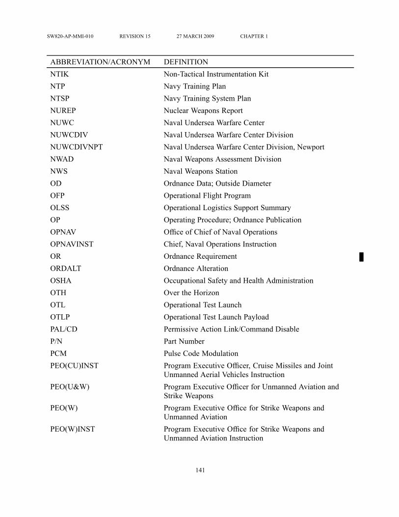
SW820-AP-MMI-010 REVISION 15 27 MARCH 2009 CHAPTER 1
ABBREVIATION/ACRONYM DEFINITIONNTIK Non-Tactical Instrumentation KitNTP Navy Training PlanNTSP Navy Training System PlanNUREP Nuclear Weapons ReportNUWC Naval Undersea Warfare CenterNUWCDIV Naval Undersea Warfare Center DivisionNUWCDIVNPT Naval Undersea Warfare Center Division, NewportNWAD Naval Weapons Assessment DivisionNWS Naval Weapons StationOD Ordnance Data; Outside DiameterOFP Operational Flight ProgramOLSS Operational Logistics Support SummaryOP Operating Procedure; Ordnance PublicationOPNAV Office of Chief of Naval OperationsOPNAVINST Chief, Naval Operations InstructionOR Ordnance RequirementORDALT Ordnance AlterationOSHA Occupational Safety and Health AdministrationOTH Over the HorizonOTL Operational Test LaunchOTLP Operational Test Launch PayloadPAL/CD Permissive Action Link/Command DisableP/N Part NumberPCM Pulse Code ModulationPEO(CU)INST Program Executive Officer, Cruise Missiles and Joint
Unmanned Aerial Vehicles InstructionPEO(U&W) Program Executive Officer for Unmanned Aviation and
Strike WeaponsPEO(W) Program Executive Office for Strike Weapons and
Unmanned AviationPEO(W)INST Program Executive Office for Strike Weapons and
Unmanned Aviation Instruction
141

SW820-AP-MMI-010 REVISION 15 27 MARCH 2009 CHAPTER 1
ABBREVIATION/ACRONYM DEFINITIONPFU Power Filter UnitPG Procedural GuidePGA Pneumatic Gauge AssemblyPHS&T Packaging, Handling, Storage and TransportationPIP Push-In-PullP/L Position LaunchPLA Plain Language AddressPMS Planned Maintenance SystemPPCA Pyro and Power Control AssemblyPPM Parts Per MillionPROM Programmable Read Only MemoryPSA Power Switching Amplifierpsid Pound(s) Per Square Inch Differentialpsig Pound(s) Per Square Inch GaugePTMCR Preliminary Technical Manual Change RequestPUB PublicationP/V Pressure/VentPV Pressure VelocityPVC Pressurization/Vent ControlPVD Pressure Vacuum DistributorPVTV Pressure Vent Test VehiclePVTV Pressure Vent Test Vehicle TOMAHAWK Test MissilePWD Programmed Warhead DemolitionQ-D Quantity-DistanceQA Quality AssuranceQAST Quality Assurance Service TestQATIP Quality Assurance Test and Inspection ProcedureQDR Quality Deficiency ReportQUICKTRANS Contractor-Operated Logistics AirliftRA Radar AltimeterRASS Random Access Storage Set
142

SW820-AP-MMI-010 REVISION 15 27 MARCH 2009 CHAPTER 1
ABBREVIATION/ACRONYM DEFINITIONRDX CycloniteREM Recovery Exercise ModuleREPROG ReprogramRF Radio FrequencyRFI Ready-For-IssueRGAP Rate Gyro/Accelerometer PackageRJA Relay Junction AssemblyRLEP Remote Launch Enable PanelRM Rocket MotorRMUC Reference Measuring Unit and ComputerRNS Radio Navigation SetROID Report of Item DiscrepancyRPB Repair Parts BreakdownRPL Repair Parts ListRPU Receiver Processor UnitRSC Range Safety CommandRSEU Range Safety Electronics UnitRSS Range Safety SystemS&TE Support and Test EquipmentS/N Serial NumberSAFEPOT Small Arms Fire Enclosure for the Protection of Ordnance
in TransitSAMDS Shore Activity Maintenance Data SystemSATCOM Satellite CommunicationsSATNAV Satellite NavigationSB Shore BaseSCG Storage Compatibility GroupSCS Submarine Combat SystemSDL Satellite Data LinkSEC SecondSHIPALT Ship Alteration
143
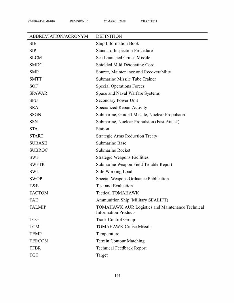
SW820-AP-MMI-010 REVISION 15 27 MARCH 2009 CHAPTER 1
ABBREVIATION/ACRONYM DEFINITIONSIB Ship Information BookSIP Standard Inspection ProcedureSLCM Sea Launched Cruise MissileSMDC Shielded Mild Detonating CordSMR Source, Maintenance and RecoverabilitySMTT Submarine Missile Tube TrainerSOF Special Operations ForcesSPAWAR Space and Naval Warfare SystemsSPU Secondary Power UnitSRA Specialized Repair ActivitySSGN Submarine, Guided-Missile, Nuclear PropulsionSSN Submarine, Nuclear Propulsion (Fast Attack)STA StationSTART Strategic Arms Reduction TreatySUBASE Submarine BaseSUBROC Submarine RocketSWF Strategic Weapons FacilitiesSWFTR Submarine Weapon Field Trouble ReportSWL Safe Working LoadSWOP Special Weapons Ordnance PublicationT&E Test and EvaluationTACTOM Tactical TOMAHAWKTAE Ammunition Ship (Military SEALIFT)TALMIP TOMAHAWK AUR Logistics and Maintenance Technical
Information ProductsTCG Track Control GroupTCM TOMAHAWK Cruise MissileTEMP TemperatureTERCOM Terrain Contour MatchingTFBR Technical Feedback ReportTGT Target
144

SW820-AP-MMI-010 REVISION 15 27 MARCH 2009 CHAPTER 1
ABBREVIATION/ACRONYM DEFINITIONTLAM Land-Attack TOMAHAWK MissileTMDER Technical Manual Deficiency/Evaluation ReportTMIS Torpedo Management Information SystemTMPS Theater Mission Planning SystemTNT TrinitrotolueneTOA Time of Arrivaltol ToleranceTOMFISH TOMAHAWK Fitment ShapeTOMIS TOMAHAWK Management Information SystemTOT Time-On-TargetTOTEM TOMAHAWK Test MissileTR Trainer (i.e., Warhead Installation Trainer TR1001)TRB Record Book for TOMAHAWK Cruise Missile, PEO(W)
PUB 4440TRNR TrainerTRS Technical Repair StandardTRT Tensioner Rigging ToolTSN TOMAHAWK Strike NetworkTTL Torpedo Tube LaunchedTVC Thrust Vector ControlTWCS TOMAHAWK Weapon Control SystemTWS TOMAHAWK Weapons System; Tactical Weapons
SimulatorTYCOM Type CommanderUBOB Umbilical Breakout BoxUIC Unit Identification CodeULSS User’s Logistics Support SummaryUOC Usable on CodeUR/IR Unsatisfactory/Information ReportURL Uniform Resource LocatorUWARS Universal Restraint Stands
145

SW820-AP-MMI-010 REVISION 15 27 MARCH 2009 CHAPTER 1
ABBREVIATION/ACRONYM DEFINITIONVDA Variable Dive Attack ManeuverVDC Volts DCVLA Vertical Launch Anti-Submarine RocketVLC Vertical Launch Console; Vertical Launch CenterVLS Vertical Launching SystemVLT Vertical Launch TOMAHAWKVLV ValveVSA Vertical Support AssemblyW/H WarheadWARHD WarheadWB Work BoatWCC Weapon Control ConsoleWDC Weapon Data ConverterWH INST TRNR TOMAHAWK Warhead Installation TrainerWIT Warhead Installation TrainerWIU Warhead Interface UnitWLC Weapon Launch ConsoleWMP Weapon Monitor PanelWPNSTA Weapons StationWSA Warhead Support Assembly
146
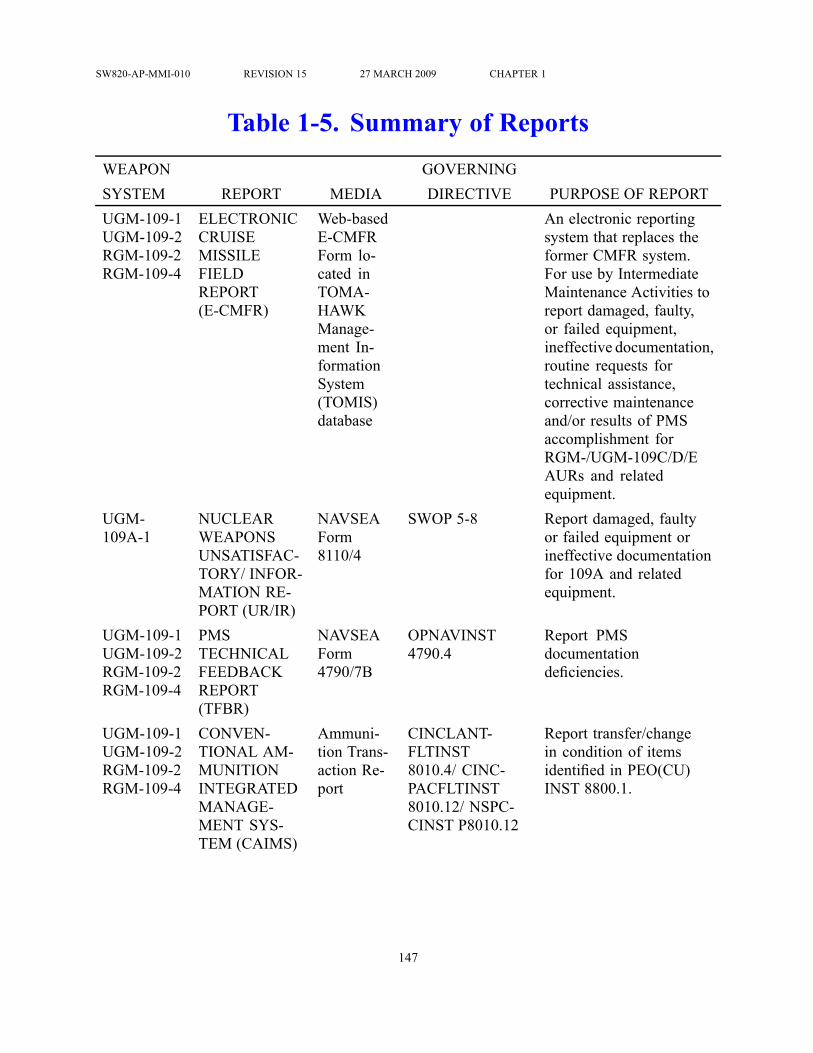
SW820-AP-MMI-010 REVISION 15 27 MARCH 2009 CHAPTER 1
Table 1-5. Summary of ReportsWEAPON GOVERNINGSYSTEM REPORT MEDIA DIRECTIVE PURPOSE OF REPORTUGM-109-1UGM-109-2RGM-109-2RGM-109-4
ELECTRONICCRUISEMISSILEFIELDREPORT(E-CMFR)
Web-basedE-CMFRForm lo-cated inTOMA-HAWKManage-ment In-formationSystem(TOMIS)database
An electronic reportingsystem that replaces theformer CMFR system.For use by IntermediateMaintenance Activities toreport damaged, faulty,or failed equipment,ineffective documentation,routine requests fortechnical assistance,corrective maintenanceand/or results of PMSaccomplishment forRGM-/UGM-109C/D/EAURs and relatedequipment.
UGM-109A-1
NUCLEARWEAPONSUNSATISFAC-TORY/ INFOR-MATION RE-PORT (UR/IR)
NAVSEAForm8110/4
SWOP 5-8 Report damaged, faultyor failed equipment orineffective documentationfor 109A and relatedequipment.
UGM-109-1UGM-109-2RGM-109-2RGM-109-4
PMSTECHNICALFEEDBACKREPORT(TFBR)
NAVSEAForm4790/7B
OPNAVINST4790.4
Report PMSdocumentationdeficiencies.
UGM-109-1UGM-109-2RGM-109-2RGM-109-4
CONVEN-TIONAL AM-MUNITIONINTEGRATEDMANAGE-MENT SYS-TEM (CAIMS)
Ammuni-tion Trans-action Re-port
CINCLANT-FLTINST8010.4/ CINC-PACFLTINST8010.12/ NSPC-CINST P8010.12
Report transfer/changein condition of itemsidentified in PEO(CU)INST 8800.1.
147

SW820-AP-MMI-010 REVISION 15 27 MARCH 2009 CHAPTER 1
WEAPON GOVERNINGSYSTEM REPORT MEDIA DIRECTIVE PURPOSE OF REPORTUGM-109-1UGM-109-2RGM-109-2RGM-109-4
PRODUCTQUALITYDEFICIENCYREPORT(QDR)
StandardForm 368
NAVSEAINST4855.7
Report receipt of defectiveAURs or material.
UGM-109-1UGM-109-2RGM-109-2RGM-109-4
REPORT OFITEM DIS-CREPANCY(ROID)
StandardForm 364
NAVMATINST4355.7
Report shipping andpackaging discrepancies
UGM-109-1UGM-109-2
SUBMARINEWEAPONFIELDTROUBLEREPORT(SWFTR)
SWFTRForm
For use by OrganizationalLevel Activities underthe cognizance ofthe Submarine TypeCommanders (TYCOMs)to report damaged, faulty,or failed equipment,ineffective documentation,routine requests fortechnical assistance,corrective maintenanceand/or results of PMSaccomplishment forUGM-109C/D/E AURsand related equipment.
UGM-109-1UGM-109-2RGM-109-2RGM-109-4
TECHNICALMANUALDEFICIENCY/EVALUATIONREPORT(TMDER)
NAVSEAForm4160/1
NAVSEAINST4160.3
Report errors, omissionsor discrepancies orrecommend changesto basic manuals.
UGM-109-1UGM-109-2RGM-109-2RGM-109-4
HAZARDOUSINCIDENTREPORT
Message OPNAVINST5102.1 for Navy/CMPINST 5102.1for contractor
Report accident or incidentwith material loss ordamage to any variantcreating hazard/potentialhazard.
148

SW820-AP-MMI-010 REVISION 15 27 MARCH 2009 CHAPTER 1
WEAPON GOVERNINGSYSTEM REPORT MEDIA DIRECTIVE PURPOSE OF REPORTRGM-109-4 CANISTER
SHORE AC-TIVITY MAIN-TENANCEDATA SUM-MARY
OP-NAVINSTForm4790/5(2A)
NAVSEAINST4790.6
Report Mk 14 Canisterpreventive andunscheduled maintenanceand defects
RGM-109-4 CANISTER/MISSILE CON-FIGURATIONSUMMARYSHORE AC-TIVITY MAIN-TENANCEDATA SUM-MARY
NAVSEAForm4790/5(2B)
NAVSEAINST4790.6
Report Mk 14 Canisterconfiguration changes toinclude encan/decan
149

SW820-AP-MMI-010 REVISION 15 27 MARCH 2009 CHAPTER 1
Table 1-6. Common Descriptive DataITEM DESCRIPTIONEngine:Designation F107-WR-400(a) or F107-WR-402(b)Type TurbofanThrust. 600 lbRocket Motor Assembly:(a)Designation Mk 106 Mod 0Type Single-chamber, fixed nozzlePropellant Arcadene 228G solid grain (304 lb)Control Jet tab thrust vectorSafe-Arm Igniter Assy Electromechanical, dual initiatorRocket Motor Assembly:(b)Designation Mk 111 Mod 0Type Single-chamber, omnidirectional nozzlePropellant UTP-25201C solid grain (349 lb)Control Nozzle thrust vectorSafe-Arm Igniter Assy Electromechanical, dual initiatorElectrical System:Shroud Converter:Type AC/DCInput 115/200V, 400Hz, 3 phase, YOutput 27.5-28.5 VdcGuidance Set Battery:Type ThermalOutput 23-33 VdcAirframe Battery:Type Thermal, dual outputOutput 1/Output 2 25-32 Vdc/26-44 VdcEngine Generator/Regulator:Type Dual output
150

SW820-AP-MMI-010 REVISION 15 27 MARCH 2009 CHAPTER 1
ITEM DESCRIPTIONOutput 28+/−1 Vdc (regulated)Output 2 24-40 Vdc (semi-regulated)REM Batteries (2):(c)Type Silver oxide-zinc, remotely activatedOutput 25-32 VdcRSS Battery:(d)Type ThermalOutput 23-33 VdcFuel: Propellant, high density synthetic hydrocarbon, JP-10,
MIL-P-87107CPneumatic System:Airframe Supply Bottle:Pressure 6000 psi (helium)Volume 39 cu inTVC Supply Bottle:(e)Pressure 6000 psi (nitrogen)Volume(g) 23 cu inVolume(h) 60 cu inREM Flotation SupplyBotles(2):(c)Pressure 6000 psi (nitrogen)Volume 60 cu in eachHydraulic System:(f)Hydraulic Reservoir/Accumulator 3550 psiPressurization/Vent System:Transducer:(g)Type Dual differential, pressure sensingRange 0.5 - 12.5 psidPressure Relief Valve:(g)Type Poppet, spring-loadedCracking Pressure 12-16 psid
151

SW820-AP-MMI-010 REVISION 15 27 MARCH 2009 CHAPTER 1
ITEM DESCRIPTIONReseat Pressure 10.8 psid (min)Pressure Relief Valve:(h)Type Poppet, spring-loadedCracking Pressure 3.4-17.0 psidReseat Pressure 3.0 psidCLS Electrical System:(h)Type VdcInput 24-30 Vdc and 4.5-5.5 VdcOutput 24-30 VdcEngine:(i)Designation Model F415-WR-400Type TurbofanThrust 650 lbRocket Motor Assembly:(i)Designation Mk 135 Mod 0Type Single-chamber, fixed nozzlePropellant Arcadene 360B HTPB, high performance, aluminized
composite propellant (322 lb)Control Jet tab thrust vectorSafe Arm Igniter Assy Mk 38Airframe Battery:(i)Type Lithium thermal, dual outputOutput 1/Output 2 28-34 Vdc/40-65 VdcAlternator:(i)Type Engine shaft mounted, three phase permanent magnet
generatorOutput 4.3 KVA (max)
152

SW820-AP-MMI-010 REVISION 15 27 MARCH 2009 CHAPTER 1
ITEM DESCRIPTIONVoltage 140-250 VoltsNOTES:
(a) - Applicable to UGM/JUGM-109A.(b) - Applicable to UGM/JUGM-109C/D only.(c) - Applicable to JRGM/JUGM-109A/C-M only.(d) - Applicable to JUGM-109C/D-S/W only.(e) - Applicable to variants with Mk 106 Mod 0 Rocket Motor only.(f) - Applicable to variants with Mk 111 Mod 0 Rocket Motor only.(g) - Applicable to UGM/JUGM-109-1 only.(h) - Applicable to UGM/JUGM-109-2 only.(i) - Applicable to JUGM/UGM-109E-1/2 only.
153

SW820-AP-MMI-010 REVISION 15 27 MARCH 2009 CHAPTER 1
Table 1-7. Variant Unique Descriptive DataITEM 109A 109C 109D 109E
Guidance: Land AttackAN/DWS-15(V)I Block III
Land AttackAN/DWS-15(V)I Block IIIw/ DSMAC orDSMAC IIA andGPSS
Land -AttackAN/DWS-15(V)I Block IIIw/ DSMAC orDSMAC IIA andGPSS
Land At-tack Guid-ance Electron-ics Unit w/DS-MAC,GPSS, andTERCOM
Warhead:Type/Weight W80Mod 0 Non-
ConventionalWDU-25/BConventionalhigh explosive(Picratol/H-6)992 lb (378 lbexplosive)
BLU-97/BConventionalhigh explosive(Cyclotol 70/30)287grams each
WDU-36/BConventionalHigh ExplosiveWarhead(PBXN-107 TypeII) 690 lb (265 lbexplosive)
Warhead:Type/Weight WDU-36/B
Conventionalhigh explosive(PBXN-107 TypeII) 690 lb (265 lbexplosive)
Fuel Capacity:TACTICAL; 1121 lb (a) 350 lb (a) 546 lb
(b)527 lb (a) 568 lb(b)
1100 lb
REM 1121 lb (a) 354 lb (a) 558 lb(b)
RSS 350 lb (a) 468 lb(b)
474 lb (a) 474 lb(b)
Warhead ArmingDevices:Dual Air Valve: FZU-43/B
Pyrotechnicactuated dualinitiator
FZU-43/BPyrotechnicactuated dualinitiator
154

SW820-AP-MMI-010 REVISION 15 27 MARCH 2009 CHAPTER 1
ITEM 109A 109C 109D 109EFuze BoosterAssemblyType FMU-138/B
Electropneu-matic armed,im-pact detonated
BBU-47/B Elec-tropneumaticarmed, pro-grammable deto-nated
Type FMU-148/BElectropneu-matic armed,programmabledetonated
NOTES:(a) - Variant with Mk 106 Mod 0 Rocket Motor(b) - Variant with Mk 111 Mod 0 Rocket Motor
155

SW820-AP-MMI-010 REVISION 15 27 MARCH 2009 CHAPTER 1
Table 1-8. Container Weights and DimensionsITEM WEIGHT LENGTH WIDTH HEIGHT
(empty) (inches) (inches) (inches)(pounds)
CNU-308/E SHIPPINGCONTAINER
1709 265.00 34.00 35.00
MK 30 SHIPPING ANDSTORAGE SKID
2650 312.63 40.00 44.00
AUR SIMULATOR SHIPPINGSKID
2700 321.19 39.12 49.88
MK 14 VLS CANISTER(w/PHS&T)
3241 280 40.34 43.45
(kilograms) (centimeters) (centimeters) (centimeters)CNU-308/E SHIPPINGCONTAINER
775 673 86 89
MK 30 SHIPPING ANDSTORAGE SKID
1202 794 102 112
AUR SIMULATOR SHIPPINGSKID
1225 816 99 127
MK 14 VLS CANISTER(w/PHS&T)
1470 711 102 110
156

SW820-AP-MMI-010 REVISION 15 27 MARCH 2009 CHAPTER 1
Table 1-9. Weights of TTL Variants and RelatedMaterial
ITEM HANDLING WEIGHT* (LBS)Pounds Kilogramslbs kg
TACTICAL AURUGM-109A-1 4273 1938UGM-109C-1 4548 2063UGM-109D-1 4391 1992UGM-109E-1 4510 2046EXERCISE AURJUGM-109A-1 4245 1926JUGM-109A-1(QAST) ** **JUGM-109C-1 4483 2033JUGM-109D-1 4367 1981TRAINING/CERTIFICATION VARIANTSTOMAHAWK TEST MISSILE (TOTEM)UTM-109-1
3550 1610
ENCAPSULATED NL TOTEM 3550 1610COMMERCIAL OFF THE SHELF (COTS) TOTEM 4050 1837PRESSURE VENT TEST VEHICLE (PVTV)TOTEM
4550 2063.9
CREW TRAINING SHAPE (CTS) UTM-109-1A 3576 1622WARHEAD INSTALLATION TRAINER (WIT) MK35/0 w/WARHEAD
4137 1877
TOMAHAWK FITMENT SHAPE (TOMFISH) MK1/0
4250 1928
VEHICLES AND CAPSULESTOTEM TEST VEHICLE TM-109-1C 2600 1179CAPSULE MK 1/0 938 425CAPSULE MK 3/0 1005 456TOTEM CAPSULE 950 431
157

SW820-AP-MMI-010 REVISION 15 27 MARCH 2009 CHAPTER 1
ITEM HANDLING WEIGHT* (LBS)Pounds Kilogramslbs kg
WIT MK 35/0 CAPSULE w/nose and slot covers 864 392WIT MK 35/0 CAPSULE w/o nose and slot covers 832 377WIT MK 35/0 TRAINER w/WARHEAD 3273 1485TTL NOSE COVER (aluminum/lightweight/BlockIV)
27/14/27 12.2/6.4/12.2
TTL FWD SLOT COVER (metal/Kevlar/Universal) 4/3/2 1.8/1.4/0.9TTL AFT SLOT COVER (metal/Kevlar/Universal) 1/1/2 0.5/0.5/0.9SHIPPING CONTAINER CNU-308/E (empty) 1709 775NOTES:
* AUR handling weights calculated using heaviest components plus a small safety factor.** Weight will vary depending on test requirements. Refer to Test and Evaluation Plan
for data.
158

SW820-AP-MMI-010 REVISION 15 27 MARCH 2009 CHAPTER 1
Table 1-10. Centers of Gravity for TTL Variants*APPROXIMATE FWDMEASUREMENT (IN)
ITEM FROM CAPSULE CGTACTICAL AURUGM-109A-1 w/ W80 Warhead 10.0UGM-109A-1 w/o W80 Warhead 2.5UGM-109C-1 12.0UGM-109D-1 11.5UGM-109E-1 10.6EXERCISE AURJUGM-109A-1 w/ NTIK or REM & Inert Warhead 10.0JUGM-109A-1w/QAST **JUGM-109C-1-M 11.5JUGM-109C-1-S/W 10.5JUGM-109D-1-S/W 11.5TRAINING/CERTIFICATION VARIANTS ANDCAPSULESTOMAHAWK TEST MISSILE (TOTEM) UTM-109-1 7.5ENCAPSULATED NL TOTEM 7.5COMMERCIAL OFF THE SHELF (COTS) TOTEM 7.5ENCAPSULATED PVTV TOTEM 20CREW TRAINING SHAPE (CTS) UTM-109-1A 6.0WARHEAD INSTALLATION TRAINER (WIT) MK 35/0w/W80
9.5
WARHEAD INSTALLATION TRAINER (WIT) MK 35/0w/o W80
3.5
TOMAHAWK FITMENT SHAPE (TOMFISH) MK 1/0 0.0CAPSULE MK 1/0, empty w/nose and slot covers 0.0CAPSULE MK 1/0, empty w/o nose and slot covers -5.0CAPSULE MK 3/0, empty w/nose and slot covers 0.0CAPSULE MK 3/0, empty w/o nose and slot covers -2.39
159

SW820-AP-MMI-010 REVISION 15 27 MARCH 2009 CHAPTER 1
*APPROXIMATE FWDMEASUREMENT (IN)
ITEM FROM CAPSULE CGTOTEM CAPSULE, empty w/ nose and slot covers 0.0TOTEM CAPSULE, empty w/o nose and slot covers -3.5WIT CAPSULE, empty w/nose and slot covers 7.0WIT CAPSULE, empty w/o nose and slot covers 2.5
*Measure from center of capsule CG stripe.AUR CG calculation is for AUR configured with Mk 111 Rocket Motor, aluminum nose
cover and slot covers installed. Add up to 1.0 inch to measurement for variants withMk 106 Mod 0 Rocket Motor. Subtract 0.5 inch from measurement with lightweightnose cover installed.
AUR/WIT/CTS CGs at station 142.1.TOTEM, NL TOTEM and COTS TOTEM Capsule CGs at station 144.0.PVTV TOTEM Capsule CG at station 155.0.** QAST CG will vary depending on test requirements. Refer to Test and Evaluation
Plan for data.
160

SW820-AP-MMI-010 REVISION 15 27 MARCH 2009 CHAPTER 1
Table 1-11. Weights of CLS Variants and RelatedMaterialMAX. HANDLINGWEIGHT (POUNDS)*
MAX. HANDLINGWEIGHT
(KILOGRAMS)*ITEM CLS Mk 45
Mod 1CLS Mk 45Mod 2
CLS Mk 45Mod 1
CLS Mk 45Mod 2
TACTICAL VARIANTS:UGM-109C-2 5905 5905 2679 2679UGM-109D-2 5749 5749 2608 2608UGM-109E-2 5900 5900 2676 2676EXERCISE VARIANTS:JUGM-109C-2 5816 TBF 2638 TBFJUGM-109D-2 5696 TBF 2584 TBFJUGM-109E-2-S/W 5625 TBF 2552 TBFJUGM-109E-2-W 5612 TBF 2546 TBFCAPSULE:Capsule Launching System Mk 45(w. CPC)
2132 2290 967 1039
Capsule Launching System Mk 45(Spent)**
2218 2376 1006 1078
MAX. HANDLINGWEIGHT (POUNDS)*
MAX. HANDLINGWEIGHT
(KILOGRAMS)*TRAINING/INERT VARIANTS:AUR VOLUMETRIC SHAPE 6800 3084AUR SIMULATOR 6870 3116AURES Mk 101 70 32AURES Mk 112 70 32Missile Tube Ballast Can (w/oadditional ballast)
6800 3084
AURBb 5680 ± 300 2576 ± 136
161

SW820-AP-MMI-010 REVISION 15 27 MARCH 2009 CHAPTER 1
MAX. HANDLINGWEIGHT (POUNDS)*
MAX. HANDLINGWEIGHT
(KILOGRAMS)*CLS Loading and Handling TrainerAssembly (Mod 1)
6390 2899
CLS Loading and Handling TrainerAssembly (Mod 2)
TBF TBF
SHIPPING SKID:Shipping and Storage Skid Mk 30Mod 2 w/covers
2650 1202
AUR Simulator Shipping Skidw/covers
2700 1225
MISCELLANEOUS:SABOT 26 12Closure Protective Cover (CPC) Mk19
84 38
Capsule Loading Cover (CLC) 17 8Clamp Ring 30 14Forward Capsule Support AdapterMk 168
50 23
CLS Uprighting Fixture Mk 26 130 59Lifting Adapter Mk 169 500 227Lifting Adapter Extension 300 136Missile Tube Extension Loader(MTEL) Mk 23
2000 907
MTEL Adapter 480 218Container, Shipping/Storage, MTELAdapter, Lifting Adapter Extension(Loaded)
2120 962
Container, Shipping/Storage, WorkPlatform (Loaded)
750 340
MTEL Shipping Pallet 1100 499Installation Guide Mk 116 185 84Hydraulic Power Unit (HPU) Mk 8 290 132Tilt Fixture, Mk 23 3000 1361
162

SW820-AP-MMI-010 REVISION 15 27 MARCH 2009 CHAPTER 1
MAX. HANDLINGWEIGHT (POUNDS)*
MAX. HANDLINGWEIGHT
(KILOGRAMS)*SSN 688 Class Loading Platform:Forward Section 5800 2631Starboard Section 3800 1724Port Section 3800 1724All Three Sections-Stacked 13400 6078SSN 774 Class Loading Platform:Forward Section 6100 2767Starboard Section 3900 1769Port Section 3900 1769All Three Sections-Stacked 13900 6305* AUR handling weights calculated using heaviest components plus a small safety factor.** Includes approximately 86-gallons (325 liters) of water.
163

SW820-AP-MMI-010 REVISION 15 27 MARCH 2009 CHAPTER 1
Table 1-12. Centers of Gravity for CLS VariantsITEM CENTER OF GRAVITY
(INCHES)CLS MK 45 1/2
TACTICAL AURUGM-109C-2 126 ± 6UGM-109D-2 127 ± 6UGM-109E-2 127 ± 6EXERCISE AURJUGM-109C-2-M 133JUGM-109C-2-S/W 132JUGM-109D-2-S/W 132JUGM-109E-2-S/W 143CAPSULE LAUNCHERSPENT CLS * 163 ± 6OTHER CENTER OF GRAVITY
(INCHES)AUR SIMULATOR SHIP SKID (LOADED) 141AUR SIMULATOR SHIP SKID (EMPTY) 160AUR SIMULATOR VOLUMETRIC SHAPE w/ AURES 153AUR SIMULATOR VOLUMETRIC SHAPE w/o AURES 155AURBb 122.51 ± 1.00MISSILE TUBE BALLAST CAN 132CLS LOADING AND HANDLING TRAINING SHAPE 127AUR variant, AUR Volumetric Shape, AURBb, AUR Simulator and CLS Loading andHandling Trainer CGs are measured from ’datum B’ (lower edge of upper flange).Missile Tube Ballast Can CG is measured from brass protector ring (flat gasket mountingsurface).AUR Simulator Shipping Skid: Trunnion end.*CG will vary for empty/spent capsule depending on amount of residual water remainingin capsule after draining.
164

SW820-AP-MMI-010 REVISION 15 27 MARCH 2009 CHAPTER 1
Table 1-13. Weights of RGM-109-2 Mk 10 Variantsand Related Material
HANDLING WEIGHT*ITEM Pounds KilogramsTACTICAL AURRGM-109C-2 3973 1802RGM-109D-2 3823 1734RGM-109E 3837.5 1741EXERCISE AURJRGM-109C-2 3973 1802JRGM-109D-2 3823 1734JRGM-109E-2 3938 1786TRAINING/CERTIFICATION VARIANTSCANISTER TRAINER MK 17 3662 1661CANISTERCANISTER MK 10 495 225NOTE:
* AUR handling weights calculated using heaviest components plus a small safety factor.
165

SW820-AP-MMI-010 REVISION 15 27 MARCH 2009 CHAPTER 1
Table 1-14. Centers of Gravity for RGM-109-2 Variants*APPROXIMATE FWDMEASUREMENT (IN)
ITEM FROM CANISTER CGTACTICAL AURRGM-109C-2 11.5RGM-109D-2 11.5RGM-109E-2 14.8EXERCISE AURJRGM-109C-2-M 11.5JRGM-109C-2-S/W 10.0JRGM-109D-2-S/W 11.5TRAINERS AND CANISTERSCANISTER TRAINER MK 17 MOD 0 0.0CANISTER MK 10 (Empty) 2.0
* Measure from center of canister CG stripe.AUR CG calculation is for AUR configured with Mk 111 Rocket Motor. Add up to 0.5
inch to measurement for variants with Mk 106 Mod 0 Rocket Motor.AUR CG at station 138.0.Mk 17 Trainer Canister CG at station 130.0.
166

SW820-AP-MMI-010 REVISION 15 27 MARCH 2009 CHAPTER 1
Table 1-15. Weights of VLS VariantsITEM * HANDLING WEIGHT
Pounds KilogramsAURJRGM/RGM-109C-4 7290 3307JRGM/RGM-109D-4 7133 3236RGM-109E-2 7154 3245TRAINERCANISTER TRAINER MK 14 6528 2961NOTE:
* Handling weights calculated using heaviest components plus a small safety factor.
167

SW820-AP-MMI-010 REVISION 15 27 MARCH 2009 CHAPTER 2
CHAPTER 2 SECURITY AND SAFETY2.1 SCOPE.This chapter discusses TOMAHAWK Weapon System (TWS) security and safety requirements,regulations and general policies relating thereto.
2.2 SECURITY.TOMAHAWK mission criticality, high cost and political sensitivity require an adequate level ofsecurity be maintained regarding security safeguards and physical protective measures used forcommercial/government transport. OPNAVINST 5530.13, PEO(CU)INST 4601.1 and NAVSEASW020-AG-SAF-010 contain specific security requirements for transport of TOMAHAWKCruise Missiles (TCM) variants over public highways. Storage and transport of TCM variantson military installations will be IAW NAVSEA OP 5, NAVSEA OP 4461 and amplifying localdirectives.
2.2.1 Security Classification. All TCMs carry a minimum security classification ofCONFIDENTIAL. OPNAVINST S5513.28 contains specific information on the securityclassification of TCM variants and their components.
2.2.2 Maintaining Unwarheaded 109A Certification. Prior to, during, and subsequent towarhead installation, the 109A variant receives no missile systems testing at the intermediatelevel. To ensure that the variant retains its certification, the following requirements apply tothe 109A without warhead installed:
a. The 109A without warhead shall be safeguarded in accordance with the provisions ofOPNAVINST 5530.13 and OPNAVINST C8126.1/DOD C-5210.41-M and shall beprotected at the same level of security provided Category II Arms, Ammunition andExplosives (AA&E).
b. Formal entry and access control shall be maintained in accordance with OPNAVINST5530.13 after the tamper resistant tape seals are broken on the shipping container.
c. Upon breaking the tamper resistant tape seals on the shipping container, the 109Ashall be provided two-person control which is defined in Special Weapons OrdnancePublication (SWOP) 4-1 as ’The close surveillance and control of materials at alltimes by a minimum of two authorized persons, each capable of detecting incorrect orunauthorized procedures with respect to the task to be performed, and each familiarwith established security requirements’.
2.2.3 Warheaded 109A. Warheaded 109A TCMs are secured, handled, maintained andtransported in accordance with applicable SWOPs.
2.2.4 Transportation Security. All shipping containers containing TCM variants are securedby wire seals. Shipping containers containing 109A variants without warhead are shipped fromthe manufacturer to the military first destination with tamper resistant tape seals, as well as wireseals, applied to the container. Additionally, the manufacturer places tamper resistant tape sealson the 109A variant prior to shipment. Tamper resistant tape seals are serially numbered with theback of the seal coated with a bar pattern release agent that will show the bars if the seal was
168

SW820-AP-MMI-010 REVISION 15 27 MARCH 2009 CHAPTER 2
removed and re-affixed or has been subjected to tampering. Serial numbers or seal identifyingdata are recorded in the Record Book for TOMAHAWK Cruise Missile, PEO(W) PUB 4440, thataccompanies each TCM variant. Seal locations are illustrated in the record book as well as inapplicable volumes of this document addressing removal/installation of seals during handlingand maintenance processes.
2.2.4.1 Receipt. During receipt inspections, tamper resistant tape and wire seals are inspectedfor integrity. Additionally, seal serial numbers/identifying data are compared with the informationcontained in the record book. If seals are missing, broken, or show evidence of tampering,compromise of the variant is suspected and Program Executive Officer for Unmanned Aviationand Strike Weapons [PEO(U&W)] (PMA-280714) as well as the applicable In-ServiceEngineering Agent are notified.
2.2.4.2 Transfer. Navy activities apply wire seals to shipping containers when transferringTCMs out of Navy custody. Additionally, activities apply tamper resistant tape seals to a 109Avariant without warhead and its shipping container prior to shipment to the depot or to anotherintermediate maintenance activity. Seal serial numbers/identifying data are recorded in the recordbook.
2.3 SAFETY.
Operations associated with the TOMAHAWK Weapons System (TWS) present a number ofsafety considerations at all levels. The TCM contains a number of hazardous components.Handling evolutions involve moving heavy weights using dollies or hoists where ’free-wheeling’or pendulum effects can occur. Operations may have to be performed under adverse conditionswhere weather or sea state can impact safety. During TCM or related equipment maintenanceprocesses, personnel may be exposed to various hazardous materials which may require the useof protective equipment or employing special procedures. To maximize safety, only qualifiedordnance certified personnel as specified in NAVSEA OP 4 and OP 5 and NAVSEAINSTs 8020.9and 8023.2 shall be used to perform TWS evolutions. Additionally, procedural volumes of thisdocument contain the general safety summary, Table 2-1 "General Safety Summary"⇒, as wellas generic and specific warnings and cautions to identify potential hazards to personnel orequipment. These warnings and/or cautions appear prior to the step or series of steps in whichpotential hazards exist.
2.3.1 Explosives Safety Quantity Distance (ESQD) Arc Restrictions. At some activities,other than designated ammunition handling facilities (i.e., WPNSTA), handling of explosives issubstantially restricted because nonexplosive ordnance activities (i.e., inhabited buildings) are inclose proximity to ordnance handling operations. To safely accommodate handling of more thanone TOMAHAWK All-UP-Round (AUR) at these ESQD restricted activities, special handlingprocedures have been developed and approved for the conventional TOMAHAWK AUR.
2.3.1.1 The concept for these special handling procedures is based on maintaining a MaximumCredible Event (MCE) of one TOMAHAWK AUR regardless of the number of AURs involved.The acknowledged ESQD arc to inhabited buildings for one conventional TOMAHAWK AUR is600 feet. The conventional TOMAHAWK AUR ESQD area is 600 feet.
169

SW820-AP-MMI-010 REVISION 15 27 MARCH 2009 CHAPTER 2
2.3.1.2 A maximum of two conventional TOMAHAWK AURs in their launch configuration,either in or out of their shipping containers, must be maintained in a nose-to-tail configurationwith respect to each other either horizontally or vertically. Other stacking restrictions regardingnumbers in stacks on or off transport vehicles still apply. This nose-to-tail configuration is tobe maintained on the bed of a truck driven onto a pier, in small boats or on the pier itself.Additionally, a maximum of two other conventional TOMAHAWK AURs in their launchconfiguration (off-loaded from combatant) may be placed in a nose to-tail configuration inspecially positioned chocks or shipping containers on the pier. All four missiles must be in anose-to-tail configuration in groups of two, and each group of two must be positioned no closerthan 10 feet side-to-side or 5 feet nose-to-tail (Figure 2-1 "Explosive Safety Quantity Distance(ESQD) Arc Restrictions (Typical)"⇒).
2.3.1.3 The use of these procedures will prevent sympathetic detonation and maintain an MCEof one conventional TOMAHAWK AUR. If ESQD restrictions are less than 600 feet to inhabitedbuildings, these procedures will not provide relief, and the requirements of NAVSEA OP 4 orOP 5 prevail. Conversely, where ESQD arcs to inhabited buildings are well beyond 600-ft arc,the ordnance handling activity may utilize the procedure to reduce, thus enhance the effect ofthe available ESQD arc. These procedures are not applicable in magazines, bunkers, workshopsor inside ships.
2.3.2 TCM Hazardous Components. TCM hazardous components range from thenonexplosive, combustible JP-10 fuel used by the TCM to cruise to the target, comparativelylow-explosive electro-explosive devices (EED) used to separate the TCM from its launchingdevice, to the highly destructive, high explosive warhead. Also included in the general category ofexplosives are the solid propellant rocket motor and the Capsule Launching System gas generator.TCM hazardous component locations are illustrated in Figure 2-2 "TOMAHAWK Cruise MissileHazardous Component Locations (2 Sheets)"⇒. All TOMAHAWK AURs are assigned to StorageCompatibility Group “J” and to a DOT Hazard Class IAW SW020–AC-SAF-010/020/030. Table2-2 "Storage and Hazard Data"⇒ summarizes storage and hazard data for all AURs. Table 2-3"Pyrotechnic and Hazardous Materials Data"⇒ provides AUR pyrotechnic and hazard dataassociated with composite material breakdown/combustion and postlaunch waste water in spentCLS capsules.
2.3.3 Permits. As all TCMs contain some hazardous materials in their shipping configurations,current Department of Transportation (DOT) Exemptions and Certifications of Equivalency(COE) are required to authorize the movement of these items. Copies of the applicable permitsmust accompany the shipment, and any special instructions contained in the permit must beobserved. The permits have the force and effect of federal law, and failure to have a permit or tocomply fully with its provisions may result in fine and/or imprisonment. The fact that a shipmentis made by or for the government in no way relieves the shipper from full compliance with permitrequirements. Five permits have been issued by federal agencies that effect shipment of TCMs.
2.3.4 Hazards Associated With Composite Material Breakdown/Combustion. CLS AURsmay be encapsulated in a steel or a composite material CLS. If a CLS made of composite materialis subjected to fire, additional precautions must be taken as outlined below and summarized inTable 2-3 "Pyrotechnic and Hazardous Materials Data"⇒.
170

SW820-AP-MMI-010 REVISION 15 27 MARCH 2009 CHAPTER 2
2.3.4.1 Composite materials composed of carbon/graphite fibers present several hazards whensubjected to fire, explosion, etc. Carbon/graphite fibers can be released into the atmosphere iftheir epoxy binder burns. When subjected to temperatures of approximately 752°F (400°C) theepoxy binder will ignite or decompose, possibly releasing fiber material. Once free, the fibers canbe transported up to several miles by air currents. The fiber material is highly conductive andfibers can potentially damage electric/electronic equipment. Mechanical agitation, especially anexplosion, can also fragment the composite causing fibers to become airborne.
2.3.4.2 Fires should be extinguished with CO2, dry chemicals (AFFF), or water. Specialfirefighting equipment such as Scott airpacks/MSAs/positive pressure self-contained breathingapparatuses will be required. Hazardous combustion by-products may consist of carbonmonoxide, carbon dioxide, acrolein, phenols, amines, aldehydes, aromatic amines, hydrofluoricacid and fluoroboric acid.
2.3.4.3 Personnel should wear protective clothing, such as:a. Disposable coveralls and shoe coversb. Gloves, preferably with leather palmsc. Safety glasses with side shields for cleanup personneld. Full face respirators for cleanup personnele. Positive-pressure self-contained breathing apparatus for firefighting personnel.
2.3.4.4 Waste materials should be collected with a vacuum cleaner equipped with HighEfficiency Particulate Air (HEPA) filter elements. Waste materials should be packaged inpolyethylene plastic bags. If sheeting or bags are not available, fibers shall be contained usingan acrylic floor wax (i.e., Wax, Floor, Water Emulsion, P-W-155C). Affected areas shall bedecontaminated by washing down and/or vacuuming. Local solid waste disposal authorities shallbe consulted for approved burial sites/techniques for composites or composite contaminatedmaterials. Local cognizant industrial hygienist or medical department representative shall beconsulted for detailed health hazard control guidance, based upon extent of exposure.
2.3.5 CLS Post-Launch Waste Water. CLS post-launch waste water has a lead (Pb)concentration consistently averaging between 5 to 10 milligrams per liter (mg/l) (particle settingmay cause concentrations to range from 1 to 5 mg/l at the top and 10 to 30 mg/l at the bottom of thecapsule) and cyanide concentration consistently between 20 to 25 mg/l. Because EnvironmentalProtection Agency regulations identify lead concentrations equal to or greater than 5 mg/l andcyanide in any amount as hazardous, CLS post-launch waste water is considered hazardous waste(HW). The internal volume of an expended CLS contains approximately 700 gallons of HW. Tubeflushing will produce approximately 300 additional gallons of HW. Therefore, approximately1,040 gallons of HW are generated during off-load of one expended CLS.
171

SW820-AP-MMI-010 REVISION 15 27 MARCH 2009 CHAPTER 2
Figure 2-1. Explosive Safety Quantity Distance (ESQD)Arc Restrictions (Typical)
172

SW820-AP-MMI-010 REVISION 15 27 MARCH 2009 CHAPTER 2
Figure 2-2. TOMAHAWK Cruise Missile HazardousComponent Locations (2 Sheets)
173

SW820-AP-MMI-010 REVISION 15 27 MARCH 2009 CHAPTER 2
174

SW820-AP-MMI-010 REVISION 15 27 MARCH 2009 CHAPTER 2
Table 2-1. General Safety SummaryGENERALOperators and maintenance personnel shall strictly observe all safety precautions applicable totheir work or duty station. Personnel are to immediately report any unsafe conditions or anyequipment that is considered unsafe.Carelessness is one of the major causes of injury to personnel. Personnel shall be thoroughlyand frequently instructed in the general safety precautions associated with the system. Shouldsituations arise which are not covered in the safety precautions presented in this or otherapplicable documents, the commanding officer, or other authorities, may issue orders as deemednecessary.For handling or maintenance of ordnance, personnel performing operations shall be qualifiedand ordnance certified IAW NAVSEA OP 4 and OP 5, NAVSEAINST 8020.9 and 8023.2 andother applicable documents. Familiarity with safety standards ASME/ANSI B30.5-1989 andB30.8-1988 will help ensure safe crane operations.The following are general safety precautions not related to any specific procedures andtherefore do not appear elsewhere in this publication. These are precautions that personnel mustunderstand and apply during many phases of operations and maintenance.LIVE CIRCUITSPersonnel must observe all safety precautions while working on and around electricalequipment. Do not replace components or make adjustments with the high voltage supplyturned on. Under certain conditions, dangerous potentials may exist when the power control isin the OFF position. To avoid casualties, always remove power and discharge and ground acircuit prior to touching it.SERVICING OR ADJUSTING EQUIPMENTUnder no circumstances should the servicing or adjusting of equipment be attempted alone. Theimmediate presence of someone capable of rendering aid is required.RESUSCITATIONPersonnel working with or near high voltages shall be thoroughly instructed in the latestmethods of cardiopulmonary resuscitation (CPR). Should someone be injured by electricity andstop breathing, begin resuscitation at once: a delay could result in the death of a victim.VENTILATIONEnsure there is adequate ventilation to vent flammable and harmful vapors. Keep away fromheat, sparks, and open flame. Avoid prolonged breathing of vapors or repeated contact withthe skin. Failure to comply may result in injury to personnel.RESPIRATORSPersonnel shall wear approved respirators when working with toxic cleaning agents, adhesives,and other toxic materials.
175

SW820-AP-MMI-010 REVISION 15 27 MARCH 2009 CHAPTER 2
FIRST AIDAn injury, no matter how slight, shall never remain unattended. First aid or medical attentionshall be given immediately.HAZARDS ASSOCIATED WITH COMPOSITE MATERIAL COMBUSTION/BREAK-DOWNComposite materials composed of carbon/graphite fibers present several hazards when subjectedto fire, explosion, etc. The epoxy binder will ignite or decompose at high temperatures,possibly releasing fiber materials. Mechanical breakdown (i.e., explosion) will also liberateand fragment fibers. Such fibers can be spread via air currents for considerable distances.Fiber material is highly conductive and can potentially damage electric/electronic equipment.Combustion by-products may consist of carbon monoxide, carbon dioxide, acrolein, phenols,amines, aldehydes, aromatic amines, hydrofluoric acid, and fluoroboric acid.COMMUNICATIONSDuring a weapon loading/handling evolution, communications must be established andmaintained among all parties (e.g., handling/loading supervisor, security, crane/hoist operators,handling personnel, damage control party) throughout the evolution. Should communicationsbecome lost to any party engaged in an evolution, stop the operation and secure the weaponuntil communications are reestablished.HAZARDOUS MATERIALS AND SITUATIONSProcedures involving hazardous materials or situations where there is potential for personnelinjury or damage to equipment are preceded by WARNING or CAUTION as appropriate.For each hazardous material used, a Material Safety Data Sheet (MSDS) shall be posted andreviewed to determine specific hazards involved, protective equipment requirements, andappropriate handling and emergency procedures to be utilized.NUCLEAR SAFETY PRECAUTIONSAll personnel performing technical operations on a TOMAHAWK Cruise Missile "A" variantcontaining the W80 Warhead must be familiar with the Nuclear Safety Rules for Operationsprovided in applicable Type Commander directives and SWOP 20-7.FUEL PRECAUTIONSTOMAHAWK Cruise Missiles are fueled with JP-10, a nonexplosive, combustible liquid. Theflashpoint for JP-10 is 130 degrees F and auto-ignition may occur at 474 degrees F.Firefighting involving JP-10 is the same as for any other hydrocarbon fuel. Carbon dioxide, drychemical and water spray are the methods used to combat fire.The probability of fuel leaking from the missile is highly unlikely since the capsule/canisteralso serves as a fuel tight barrier. In the event leakage should occur, the affected areas should bewrapped in Buna-N rubber sheeting and/or ordnance tape to provide a fuel tight seal.
176

SW820-AP-MMI-010 REVISION 15 27 MARCH 2009 CHAPTER 2
Do not use organic cartridge respirators or oxygen breathing apparatus to combat fuel associatedcasualties, including cleanup of spills or combustion by-products. A minimum of two personnelshall be present during operations involving fuel spills. No smoking, matches, or open flamesare permitted in the area of a fuel spill.EXPLOSIVE HAZARDSThe TOMAHAWK Cruise Missile contains a number of explosive components. They rangefrom comparatively low-explosive electroexplosive devices (EED) to the highly destructive,high explosive warhead. Also included in the general category of explosives is the solidpropellant rocket motor. General safety precautions regarding handling and storage ofexplosives shall be observed at all times. Personnel shall be familiar with the operatingprocedures and precautions necessary to prevent the spurious initiation of EEDs. Areascontaining explosives shall be clearly posted with the appropriate warning signs. See NAVSEAOP 4 and OP 5.POST LAUNCH WASTE WATER DISPOSALRemoval of post launch waste water from expended capsules involves handling material whichis not authorized for direct dumping into coastal or inland waters. In many locations, disposalof post launch waste water into shore sewage systems is prohibited. Contact the local publicworks department and advise them of detailed disposal considerations to obtain guidancefor waste water disposal.SAFETY HARNESSESPersonnel performing over-the-side operations or working in or around open hatches/missiletubes shall wear safety harnesses with safety lines secured.LITHIUM BATTERIESREM-equipped TOMAHAWK missiles contain two lithium active battery packs, one usedto power the recovery beacon and one used to power a special instrumentation electronicspackage. Lithium active batteries can become hazardous if the case is ruptured or the leadsare shorted together causing the battery to discharge at a high rate. Either situation can causea violent chemical reaction, the venting of potentially hazardous gasses including sulfurdioxide (SO2), hydrochloric acid (HCl), sulfuric acid (H2SO4), and sulfurous acid (H2SO3), andpossible explosion. This violent reaction can also be caused by water entering the batterythrough a rupture in the case. Extreme care shall be used when disconnecting the active lithiumbatteries to prevent the leads from shorting. Cease all operations and notify Explosive OrdnanceDisposal (EOD) if a ruptured or crushed lithium battery is observed. Do not spray water intothe REM compartment during missile washdown or decontamination operations.
177

SW820-AP-MMI-010 REVISION 15 27 MARCH 2009 CHAPTER 2
Table 2-2. Storage and Hazard DataQ-D CLASS 1.1DOT HAZARD MARKING "ROCKET AMMUNITION W/EXPLOSIVE PROJECTILE"UN ID No.: UN0397
RGM/UGM-109C w/WDU-25/B/WDU-36/B Warhead, Rocket Motor Mk 106 Mod 0/Mk111 Mod 0 and Liquid Sustainer Engine (Land Attack-Conventional)
JRGM/JUGM-109C-W w/WDU-25/B/WDU-36/B Warhead, RSS, RocketMotor Mk 106 Mod 0/Mk 111 Mod 0 and Liquid Sustainer Engine (LandAttack-Conventional-Exercise)
RGM/UGM-109D w/BLU-97/B Payload Module (Kit-001/-002), RocketMotor Mk 106 Mod 0/Mk 111 Mod 0 and Liquid Sustainer Engine (LandAttack-Conventional-Submunition)
JRGM/UGM-109D-W w/BLU-97/B Payload Module (Kit-003/-004), RSS,Rocket Motor Mk 111 Mod 0 and Liquid Sustainer Engine (LandAttack-Conventional-Submunitions-Exercise)
RGM/UGM-109E w/WDU-36/B Warhead, Rocket Motor Mk 135 Mod 0 and LiquidSustainer Engine (Land Attack-Conventional)
Q-D CLASS 1.3DOT HAZARD MARKING "ROCKET MOTOR, CLASS B EXPLOSIVE"UN ID No.: all UN0396
UGM-109A with W80 Warhead, Rocket Motor Mk 106 Mod 0 and Liquid SustainerEngine (Land Attack)
UGM-109A w/o W80 Warhead, Rocket Motor Mk 106 Mod 0 and Liquid SustainerEngine (Land Attack)
JUGM-109A-M/S w/ or w/o Inert W80 Warhead, REM or RSS, Rocket Motor Mk 106Mod 0 and Liquid Sustainer Engine (Land Attack-Exercise)
JRGM/JUGM-109C-M/S w/Inert Warhead, REM or RSS, Rocket Motor Mk 106 Mod0/Mk 111 Mod 0 and Liquid Sustainer Engine (Land Attack-Conventional-Exercise)
JRGM/JUGM-109D w/Inert Submunitions or Functional Indicator BLU-97/B Payload(Kit 003), RSS, Rocket Motor Mk 106 Mod 0/Mk 111 Mod 0 and Liquid SustainerEngine (Land Attack-Conventional-Submunitions-Exercise)
JRGM/JUGM-109E w/Inert Warhead, REM or RSS, Rocket Motor Mk 135 Mod 0 andLiquid Sustainer Engine (Land Attack-Conventional-Exercise)
178

SW820-AP-MMI-010 REVISION 15 27 MARCH 2009 CHAPTER 2
Table 2-3. Pyrotechnic and Hazardous Materials DataITEM HAZARDROCKET MOTOR Mk 106/0 = 304 lb propellant; Mk 111/0 = 349 lb
propellant; Mk 135/0 = 322 lb propellantCONVENTIONAL WARHEAD WDU-25/B = 378 lb explosive WDU-36/B = 265 lb
explosivePAYLOAD MODULE BLU-97/B = 106 lb explosiveFUEL JP-10 Flashpoint (FP) = 130 degrees F Auto-Ignition Temperature
= 474 degrees FCLS SEPARATION NUTINITIATORS (4)
Zirconium Potassium Perchlorate/TitaniumHydride/Potassium Perchlorate Mixture = 295milligrams
CLS GAS GENERATOR Class B Pyrotechnic Propellant Grain Material = 7 lbCLS IGNITER Boron/Potassium Nitrate Binder Mixture = 100 gramsCLS GAS GENERATOR EBWINITIATOR
Boron Phosphate Nitrate/Superfine RDX Mixture = 240milligrams
GN2 BOTTLES 6000 psi for Mk 106/0 Rocket Motor thrust vector control;5000 psi for REM flotation system
He BOTTLES 6000 psi for air frame wing slots, wings, and inletdeployment jet tab control
HYDRAULIC RESERVOIR/AC-CUMULATOR
3500 psi for Mk 111/0 Rocket Motor thrust vector control
BLEED AIR VALVE Zirconium/potassium perchlorate (65 mg) and Titaniumhydride/potassium perchlorate (220 mg)
FUEL SYSTEM ISOLATIONVALVE
Zirconium/potassium perchlorate (65 mg) and Titaniumhydride/potassium perchlorate (220 mg)
BOOSTER IGNITER BKNO3 Pellets, 107.5 gmBOOSTER SEPARATION RING (FLSC)/CH6 (5.76 gm) and Loaded Charge Case HNS
(.17 gm)SHROUD EXPLOSIVE BOLT ZPP (16 mg), Lead azide (14 mg) and RDX (200 mg)CABLE CUTTER Zirconium/potassium perchlorate (65 mg) and Titanium
hydride/potassium perchlorate (220 mg)INLET COVER THRUSTER Zirconium/potassium perchlorate (65 mg) and Titanium
hydride/potassium perchlorate (220 mg)
179

SW820-AP-MMI-010 REVISION 15 27 MARCH 2009 CHAPTER 2
ITEM HAZARDENGINE START CARTRIDGEAND IGNITERS
Ammonium nitrate based propellant (298 gm), Igniter mixIB-43, and Boron/potassium nitrate (17.5 gm)
WING PLUG THRUSTERS Zirconium/potassium perchlorate (65 mg) and Titaniumhydride/potassium perchlorate (220 mg)
WING DEPLOYMENTPNEUMATIC VALVES
Zirconium/potassium perchlorate (65 mg) and Titaniumhydride/potassium perchlorate (220 mg)
FIN CABLE CUTTER Hercules Hi Temp (Boron, Calcium Chlorate, TelluriumDioxide, Viton B) (285 gm)
FIN DEPLOYMENT SYSTEMPYROTECHNIC LINEARACTUATORS (UGM-109E)
1.3C Main Charge Talley TAL 11.0g, 1526 HTB EnhancedThiokol 2D 140 mg Pellet, Equivalent to MIL-P-46994A11B Pellet
CMA BATTERY Iron sulfide, lithium fluoride, potassium chloride, lithiumbromide, magnesium oxide, Iron powder (MH 100 and NH100), Cab-O-Sil, potassium perchlorate
NOTE: Refer to SW020-AC-SAF-010/-020/-030 for Net Explosive WeightsCOMPOSITE CLS HAZARD INFORMATIONComposite materials in the Composite CLS are reinforced with carbon/graphite
fibers to provide stiffness, high strength-to-weight ratio, and ease of fabrication.Carbon/graphite fibers can be released into the atmosphere if their epoxy binderburns. (approximately 752 degrees F (400 degrees C) will cause epoxy binder toignite or decompose.) Once free, the small lightweight fibers can be transportedup to several miles by air currents. Because of their high electrical conductivity,they can damage unprotected electrical/electronic equipment. Similarly, mechanicalagitation, especially an explosion, can fragment the composite and cause fibers tobecome airborne.
EXTINGUISHING AGENTS: Carbon dioxide; dry chemical (AFFF); water.SPECIAL FIREFIGHTING EQUIPMENT: Scott air packs; mine safety apparatus (MSA);
or positive pressure self-contained breathing apparatus.HAZARDOUS PRODUCTS OF COMBUSTION: carbon monoxide, carbon dioxide;
acrolein; phenols; amines; aldehydes; aromatic amines; and hydrofluoric andfluoroboric acids.
PERSONNEL PROTECTIVE EQUIPMENT:a. All personnel - Disposable coveralls and shoe covers; gloves (leather palm preferred)b. Firefighters - Positive pressure self-contained breathing apparatusc. Clean-up personnel - Full face respirator; safety glasses w/side shield.
180

SW820-AP-MMI-010 REVISION 15 27 MARCH 2009 CHAPTER 2
ITEM HAZARDCLEAN-UP MATERIALS: Polyethylene sheeting and tape (for containing debris);
vacuum cleaner equipped w/High Efficiency Particulate Air (HEPA) filter elements;polyethylene bags; water emulsion floor wax (P-W-155C (NSN 7930-00-141-5888)).
HAZARDOUS WASTE DISPOSAL: Local solid waste disposal authoritiesshall be consulted for approved burial sites/techniques for composites orcomposite-contaminated materials. In addition, the local cognizant industrialhygienist or medical department representative should be consulted for detail healthhazard control, guidance, based upon extent of exposure.
POST-LAUNCH WASTE WATER IN SPENT CLS CAPSULES: Removal of post-launchwater from expended CLS capsules involves handling material which may be harmfulto personnel and which is not authorized for direct dumping into coastal or inlandwaters.
181

SW820-AP-MMI-010 REVISION 15 27 MARCH 2009 CHAPTER 3
CHAPTER 3 FUNCTIONAL DESCRIPTIONSECTION I. CHAPTER ORGANIZATION
3.1 SCOPE.This chapter discusses functional descriptions of TOMAHAWK Cruise Missile (TCM)components and systems as well as interfaces between the TCM and its launch platform. SectionII discusses the TCM electrical power system and type commands and requests for status issuedto the TCM by the launch platform systems and TCM responses to those commands and requestsfor status which are, in general, common among all TCMs irrespective of launch platform.Section III discusses unique interfaces between torpedo tube launch TCMs and the submarine.Section IV discusses unique interfaces between Capsule Launching System (CLS) TCMs and thesubmarine. Section V discusses unique interfaces between Vertical Launching System (VLS)TCMs and the surface ship.
182

SW820-AP-MMI-010 REVISION 15 27 MARCH 2009 CHAPTER 3
SECTION II. GENERAL3.2 ELECTRICAL POWER SYSTEM.The TCM electrical power system consists of a dc monitor/reset power bus, regulated bus,semi-regulated bus, and a Cruise Missile Airframe (CMA) bus, a Mission Control Module(MCM) bus, a pyro bus and an arm battery activate bus.
3.2.1 Prelaunch Electrical Power. The launch platform’s electrical power distribution systemconverts 3-phase 400 Hz delta power to 3-phase wye power to provide operating power for themissile; provide single phase wye power for Recovery Exercise Module (REM) heater power; anddc power for commands to and responses from the TCM. The routing of power in the missile isdescribed in the following paragraphs.
3.2.1.1 Converter/Operate Power. Ship wye power is routed to the TCM ac-dc converter. Thedc output of the converter is connected to the missile REGULATED bus via the POWER BUScontrol relay. For land-attack TCMs, power is fed to the DSMAC set, GPSS (109C and 109Donly) and the CMGS from the REGULATED bus. For all TCMs, power is also fed throughthe normally closed contacts of the BUS ISOLATE relay to power the CMA and MCM buses.The CMA bus supplies power to the airframe electrical equipment. The MCM bus powers thedecoder/relay drivers inside the MCM.
3.2.1.2 Cruise Missile (CM) Identification Power. The dc CM identification power is appliedto the TCM when the launch operator selects the missile designated for launch. Power is routedback to confirm the identity of the TCM selected and permit it to be prepared for launch or toadvise the launch operator that there is a mismatch between the TCM selected and the actual TCMin the launching device. In the latter instance, further processing is automatically precluded.
3.2.1.3 REM Heater Power. When the launch operator selects a REM-equipped TCM andthe identity of the TCM has been confirmed, power is applied to the REM battery heaters. Theheaters warm the battery electrolyte in preparation for REM battery activation.
3.2.1.4 Monitor/Reset Power. A dc monitor/reset voltage is applied to the DCMONITOR/RESET POWER bus. The DC MONITOR/RESET POWER bus powers thesubmarine launch TCM dual differential pressure transducer, the WARHEAD DEADFACErelay (109A) and the rocket motor safe-arm monitoring circuits. The bus also supplies powerto energize the POWER BUS CONTROL relay and connects the ac-dc converter output to themissile REGULATED bus. It supplies power to energize the FIRST MOTION relay via the firstmotion loop to generate the MISSILE ENABLED mark that is sent prior to missile launch.
3.2.1.5 DC Monitor/Reset Power Return. The DC MONITOR/RESET POWER RETURNprovides the return leg back for dc monitor/reset power.
3.2.1.6 Chassis/Static Ground. A copper ground path is provided to assure that the launchplatform and missile are at the same ground potential.
3.2.2 Launch/Boost Electrical Power. Launch/boost electrical power is supplied by tworemotely activated thermal batteries. One battery, located in the missile midbody, is the CMAbattery. The second battery is the BPU located in the CMGS (109C/D). A REM-equipped TCM
183

SW820-AP-MMI-010 REVISION 15 27 MARCH 2009 CHAPTER 3
also has two electrically activated REM batteries. The CMA and CMGS batteries supply shortduration power (about 30 seconds) to power the TCM until the engine-driven generator/regulatorcan take over. The REM batteries power REM subsystems and, once activated, last about 15hours. Activation of batteries is described in the following paragraphs.
3.2.2.1 CMA Battery Activation. When the launch operator sets the switch to FIRE (Intent toLaunch (ITL), DC power is routed to the coil of the ARM BATTERY ACTIVATE BUS relay.The relay energizes and applies CMA bus power to the ARM BATTERY ACTIVATE bus.Upon CMGS command, the CMA BATTERY ACTIVATE relay energizes and fires the batterypyros to activate the battery. Output 1 powers the MCM and CMA buses. Output 2 powers theSEMI-REGULATED bus, which in turn, supplies power to the fin servoactuators.
3.2.2.2 CMGS Battery Activation. The CMA battery output is sensed by the MCM. When thespecified voltage is attained, a CMA BATTERY GO signal is sent to the CMGS. Upon CMGScommand, the CMGS BATTERY ACTIVATE relay energizes and applies power to fire the CMGSbattery pyros. Battery output is applied to the CMGS subsystems and the REGULATED bus.
3.2.2.3 REM Battery Activation. To allow time to activate the REM batteries and perform theREM BIT, about 29 seconds are added between ITL and CMA battery activation. REM batteryactivation begins when the REM ACTIVATE command is issued by the CMGS after receipt ofITL. BATTERY ACTIVATE power is provided by the ARM BATTERY ACTIVATE bus. Uponreceipt of REM ACTIVATE, the REM performs a pre-battery activate BIT. If REM BIT fails, theREM will not issue the REM ENABLE command and, as a result, the MISSILE ENABLED signalwill not be sent. If BIT passes, the REM batteries activate and post-battery activate BIT is begun.
3.2.2.4 Bus Isolation. Battery power is supplied only to those circuits essential to thelaunch/boost phase. For a land-attack TCM, power-up of the BPU is sensed by the CMGSRMUC. The RMUC, in turn, sends a discrete coded word to the MCM. From the MCM, power isapplied to the coil of the BUS ISOLATE relay. The relay energizes to isolate the REGULATEDbus from the MCM and CMA buses. The BUS ISOLATE relay remains energized until theengine-driven generator/regulator comes on line during the transition to cruise flight.
3.2.2.5 First Motion. Upon first motion, the electrical connection between the TCM and thelaunch platform is disconnected and deenergizes the FIRST MOTION relay. The opening of relaycontacts is sensed by the CMGS, which starts the safe eject test. The ARM ENABLE relayenergizes and the normally open contacts of the ARM ENABLE relay close, applying power tothe normally-open contacts of the SAFE/ARM relay. The CMGS confirms safe eject velocityand distance, then commands the MCM to energize the SAFE/ARM relay. This action routeselectrical power from the CMA battery to energize the PYRO bus. The SAFE EJECT relayenergizes, completing the circuits that hold the SAFE EJECT relay and the ARM ENABLE relayenergized. The PYRO bus supplies the power to activate the CMA pyros. The PYRO bus remainsenergized until the completion of transition to cruise flight.
3.2.3 Cruise Electrical Power. After the sustainer engine has started and comes up to speed, adual-output generator/regulator assumes the airframe and CMGS electrical loads. Output 1 isdedicated to the CMGS and airframe equipment. Output 2 serves the fin servoactuator system.Load transients occurring on Output 2 have no influence on Output 1.
184

SW820-AP-MMI-010 REVISION 15 27 MARCH 2009 CHAPTER 3
3.2.4 RSS Thermal Battery Activation. In the event that an RSS-equipped TCM loses cruiseelectrical power, the RSS thermal battery is activated to provide electrical power to close thethrottle and initiate fin flip, thus aborting the mission.
3.3 DIGITAL DATA LINK.Communications between the TCM and the launching platform is performed via the digital datalines. The lines consist of four pairs of twisted wires (1 true and 1 complement per pair). Alsoprovided are a shield carry-through and a digital I/O power supply return. The lines are connectedwhen the launch operator selects the designated missile and disconnected prior to launch. Thedigital data link utilizes serial 17 bit (16 data and 1 odd parity) data words. The least significantbit is sent first and the parity bit is sent last. The first word is always the same in every data block,and is used to initialize the CMGS/launch platform system interface software. The second word isalways a control word to request status or identify the data block and the number of data wordswithin the data block. The last word in the data block is a checksum (2’s complement addition)of the control word and all following data words. Information transferred over the digital datalink includes the operational flight program, platform alignment data, missile status/commandsequences and mission data (land-attack TCM). The digital data lines used for communication are:
a. DATA ENABLE - Lines used to send the DATA ENABLE command, a discrete signal,to permit the RMUC to accept and transmit data.
b. CLOCK - Lines used to send timing signals to synchronize commands and data.c. DATA UPLINK - Lines used to transmit digital data sent to the RMUC.d. DATA DOWNLINK - Lines used to transmit digital data from the RMUC.e. SHIELD CARRY THROUGH - Line used to provide shield continuity on wires carrying
digital data. The shield is floated at the launch platform and grounded in the missile.f. DIGITAL I/O POWER SUPPLY RETURN - Line used to provide a common ground
reference for digital input/output power to the I/O channel power supply and the CMGS.
3.4 DIGITAL COMMANDS/DATA BLOCKS SENT TO A LAND-ATTACKTCM.Digital commands and data blocks sent to a land-attack TCM over the digital data link discussedin paragraph 3.3⇒ are described in the following paragraphs. Commands unique to a CLSTCM are discussed in Section IV.
3.4.1 Bootstrap Load (Program). A BOOTSTRAP LOAD program permits the loading ofprograms into the RMUC. When REPROGRAM discrete is received by the RMUC, it activatesthe Programmable Read Only Memory (PROM) and reestablishes the serial data link. Theprogram is loaded into computer memory and data transmission begins.
3.4.2 Request Status. The REQUEST STATUS block is sent once every second to request ago/no-go summary of missile BIT results. It is also used to request the present operating modeof the CMGS (e.g., warmup, coarse level, navigate (Table 3-1 "Land-Attack TCM CMGSAlignment Modes"⇒).
185

SW820-AP-MMI-010 REVISION 15 27 MARCH 2009 CHAPTER 3
3.4.3 Alignment Data. The ALIGNMENT DATA block is sent once every second to sendreference data to align the CMGS inertial platform relative to the launch platform inertialreference system. Alignment data blocks continue to be sent until the missile is commanded toterminate alignment.
3.4.4 Mission Data. The MISSION DATA block includes target characteristics, waypoints,guidance parameters, terrain correlation maps and DSMAC scenes (109C and 109D only). It alsoidentifies the type missile and the type mission to be flown. Each group is sent by a unique datablock that is repeatedly sent until all data for that group are transferred to the CMGS.
3.4.5 Battery Activate. Receipt of the ITL command causes the CMGS to initiate the batteryactivate sequence. For a tactical TCM, the CMA battery activates first, followed by the CMGSbattery. For a REM-equipped TCM, the REM batteries activate first, followed by the CMAand CMGS batteries.
3.4.6 Launch Sequence Command. The LAUNCH SEQUENCE COMMAND block isused to reinitialize the RMUC, terminate CMGS alignment, zero mission data, shut down theCMGS, and declassify the CMGS memory. When the REINITIALIZE command is sent, theCMGS recycles to Mode 0, begins normal operation to transfer mission data and begins a newalignment. (For an explanation of alignment modes, see Table 3-1 "Land-Attack TCM CMGSAlignment Modes"⇒.) When the TERMINATE ALIGNMENT command is sent, the RMUCcontinues to accept alignment data and switches to the NAVIGATION mode. At this time, theCMGS becomes an independent navigator. The ZERO MISSION DATA command causes theprogram to zero all memory locations dedicated to mission data. The SHUT DOWN CMGScommand causes the CMGS to perform a controlled shutdown that includes a gyro despin topreclude gyro damage. The DECLASSIFY CMGS MEMORY command is used to declassify theCMGS memory following an abort.
3.5 DIGITAL DATA RESPONSES FROM A LAND-ATTACK TCM.Two types of digital data responses are sent by the missile. The first, GOOD DATA word, is sentafter receipt of each data block that passes the parity and checksum tests. The second, MISSILESTATUS word, is sent in response to a status request.
3.5.1 Good Data Word. As the CMGS accepts data, each word is checked for odd parity. Thedata words are read, stored in a data table, and added to form a checksum that is checked againstthe checksum word at the end of the data list. If the word parities are good and checksums agree,a GOOD DATA word is sent (except in response to a missile status request).
3.5.2 Missile Status Word. The MISSILE STATUS word, sent once every second in responseto a status request, shows the results of pre-launch BIT via a combination of software commandedand hardware continuous tests conducted by the CMGS prior to MISSILE ENABLED. It alsoshows the present mode of the CMGS. The CMGS software will decode any BIT failure andtransmit the information to the launch platform as a zero bit in the appropriate bit position of theMISSILE STATUS word.
3.6 DISCRETE COMMANDS SENT TO A TCM.
186

SW820-AP-MMI-010 REVISION 15 27 MARCH 2009 CHAPTER 3
The following paragraphs discuss discrete commands issued to the TCM by the launch platform.Discrete commands unique to CLS are discussed in Section IV.
3.6.1 Booster Safe Command. The BOOSTER SAFE command is a dc signal that sets therocket motor in the SAFE position.
3.6.1.1 Mk 106 Rocket Motor. For the Mk 106 Rocket Motor, the BOOSTER SAFEcommand interrupts the armed holding circuit. The command allows the safe-arm mechanismto spring-return to SAFE, thus positioning a physical barrier between the igniter initiators andpropellant igniter. The signal is applied continuously until the BOOSTER ARM command isreceived.
3.6.1.2 Mk 111 Rocket Motor. For the Mk 111 Rocket Motor, the safe-arm indicator plate isheld in the SAFE position by spring tension. In the safe position, the safe-arm indicator platewill not complete the electrical circuit to the bridgewires and ARM monitor which are necessaryfor rocket motor ignition. It also prevents the proper alignment of the barrier slots with thepoppet slots and consequently prevents a vent path for the initiator output to reach the igniter andsubsequent rocket motor ignition. The Mk 111 Rocket Motor will remain in SAFE position untilsuch time as the BOOSTER ARM command is received. The Mk 111 Rocket Motor arming-firingdevice cannot be manually safed.
3.6.2 Booster Arm Command. The BOOSTER ARM command is a dc signal that places therocket motor in the ARMED position.
3.6.2.1 Mk 106 Rocket Motor. For the Mk 106 Rocket Motor, the BOOSTER ARM commandremoves the physical barrier between the igniter initiators and propellant igniter to arm the rocketmotor.
3.6.2.2 Mk 111 Rocket Motor. For the Mk 111 Rocket Motor, the BOOSTER ARM commandis sent to the solenoid rotor of the arming-firing device. The energized rotor causes the safe-armindicator plate to rotate, which in turn moves the sweep contacts on the switch plate assembly tocomplete the electrical circuit to the pyros and aligns the barrier slots to allow initiator output toreach the igniter explosive thereby arming the rocket motor.
3.6.3 Warhead Safe Control/Command (109A only). The WARHEAD SAFEcontrol/command is a dc signal that sets the warhead to the safe condition.
3.6.4 Warhead Prearm Control/Command (109A only). The WARHEAD PREARMcontrol/command is a unique signal placing the warhead in the prearmed condition.
3.6.5 Reprogram Command (Land-Attack only). The REPROGRAM command is a dcsignal that allows the CMGS to be reprogrammed. It zeros the RMUC memory except forcalibration coefficients. To prevent gyro damage, this command is never issued without firstperforming a controlled shutdown of the CMGS.
3.6.6 Fire Command or Intent to Launch. The FIRE or ITL command is a dc signal thatenergizes the ARM BATTERY ACTIVATE BUS relay. The CMA battery activates first, followedby the CMGS battery about one second later. For a REM-equipped missile, the REM batteriesactivate first, followed by the CMA and CMGS batteries.
187

SW820-AP-MMI-010 REVISION 15 27 MARCH 2009 CHAPTER 3
3.6.7 REM Abort Command. The REM ABORT command is a dc signal that disconnects theREM batteries which results in a turnoff of all REM-battery-powered equipment.
3.7 DISCRETE SIGNALS SENT FROM A TCM.The following paragraphs discuss the discrete signals transmitted from a TCM to the launchplatform. Discrete signals unique to CLS are discussed in Section IV.
3.7.1 Weapon Identification. Electrical identification of the TCM is derived from CMidentification power. Decode circuit defects open on the identification lines not applicable to theidentified TCM. Weapon identification also allows the launch platform to configure for REM andapplies ac power to the REM battery heaters.
3.7.2 Simulator Present. SIMULATOR PRESENT is a continuity to DC MONITOR/RESETPOWER that indicates that a simulator is connected instead of an actual TCM.
3.7.3 Booster Safe Monitor. The BOOSTER SAFE monitor is a continuity to DCMONITOR/RESET POWER that indicates the rocket motor igniter is safed.
3.7.4 Booster Armed Monitor. The BOOSTER ARMED monitor is a continuity to DCMONITOR/RESET POWER that indicates the rocket motor igniter is armed.
3.7.5 Warhead Safe Monitor (109A only). The WARHEAD SAFE monitor is a continuity toDC MONITOR/RESET POWER RETURN that indicates the warhead has been safed.
3.7.6 Warhead Prearmed Monitor (109A only). The WARHEAD PREARMED monitor is acontinuity to DC MONITOR/RESET POWER RETURN that indicates the warhead has beenprearmed.
3.7.7 Missile Bus Monitor. The MISSILE BUS monitor is a dc signal that monitors the dcoutput of the ac-dc converter. Upon loss of voltage, prior to MISSILE ENABLED, the launchplatform automatically safes the warhead (109A only) and rocket motor igniter.
3.7.8 Missile Enabled. MISSILE ENABLED is a continuity to DC MONITOR/RESETPOWER that indicates the missile batteries have been successfully activated, BIT has passed andthe MISSILE STATUS word is good. The signal is combined in software with other conditionsto complete the closing of firing interlocks. For a REM/RSS-equipped missile, the MISSILEENABLED signal is routed through the REM/RSS. Before the MISSILE ENABLED signal canbe sent, the REM/RSS must first pass all REM/RSS BIT’s and issue a REM/RSS ENABLED tocomplete the circuit.
3.7.9 Differential Pressure (TTL only). Because encapsulated TTL TCMs are subjected topressure differences when in a flooded torpedo tube prior to launch, two dc signals (A and B)are provided by the missile dual differential pressure transducer to indicate differential pressurebetween the shroud compartment and ambient outside pressure. The redundant signals, whichare derived from DC MONITOR/RESET POWER, are used to monitor the missile pressureand provide a PRESSURE IN BAND signal.
188

SW820-AP-MMI-010 REVISION 15 27 MARCH 2009 CHAPTER 3
SECTION III. TORPEDO TUBE LAUNCH3.8 GENERAL.This section discusses launch platform and TCM physical and functional interfaces aboard thesubmarine. These interfaces include missile/capsule and torpedo tube physical interfaces as wellas the submarine systems utilized to:
a. Maintain pressure in TCMs during preparation for launch.b. Secure and prevent unauthorized launch of the UGM-109A-1.c. Compute TCM attack solutions.
3.9 MISSILE/CAPSULE AND TORPEDO TUBE PHYSICAL INTERFACES.The missile/capsule and torpedo tube physical interfaces consist of the mechanical, electrical andpneumatic interfaces described in the following paragraphs.
3.9.1 Mechanical Interfaces. The mechanical interfaces consist of the following restrainingdevices:
a. Loading button on the capsule barrel closure to load/unload the missile/capsule from thetorpedo tube.
b. Two guide studs on the capsule barrel to align the capsule in the torpedo tube. Theforward guide stud also engages the tube stop bolt.
c. Two shear holdback assemblies to restrain the missile in the capsule until ejection.d. Two spring-loaded latches at the aft end of the capsule to restrain the capsule in torpedo
tube (UGM-109A/C/D-1).e. Capsule retention fixture installed on the capsule to restrain the capsule in the torpedo
tube. The retention fixture also houses a clamp that is removed and installed on thecapsule barrel closure in order to secure the eletrical umbilical cable (UGM-109E-1).
3.9.2 Electrical and Pneumatic Interfaces. The electrical and pneumatic interfaces consist ofthe electrical and pneumatic umbilical discussed below. The routing of the umbilicals is shown inFigure 3-1 "TTL Electrical and Pneumatic Umbilical Routing (2 Sheets)"⇒.
3.9.2.1 Electrical Umbilical. The electrical umbilical connects between the breech door andthe missile to transfer power/commands and status signals between the missile and submarinecombat system.
3.9.2.2 Pneumatic Umbilical. The pneumatic umbilical connects between the breech door andthe capsule to connect the PVC system to pressurize the missile and supply pneumatic pressure toclose the capsule flow slots in preparation for capsule ejection, when authorized.
3.10 PRESSURIZATION/VENT CONTROL SYSTEM.The PVC system features independent four-tube controls to regulate internal TCM pressureto withstand sea ambient pressure during pre-launch operations. With the electrical andpneumatic umbilicals connected to the TCM and the PVC system activated, dual-differentialtransducers in the TCM (one operator selected and one alternate) compare internal free volume
189

SW820-AP-MMI-010 REVISION 15 27 MARCH 2009 CHAPTER 3
pressure with outside ambient pressure and output signals to PVC system equipment. Thesignals energize/deenergize manifold pressure/vent block solenoids which permit pressurizationor venting to occur in order to maintain TCM internal pressure within prescribed limits.When pressure is not within prescribed limits, the system inhibits launch until the TCM ispressurized/vented and the PRESSURE IN BAND indication is restored. Should the selectedtransducer fail, the system automatically vents the TCM and likewise inhibits launch until theoperator selects the alternate transducer and the PRESSURE IN BAND indication is restored.Should the automatic PVC system fail, the PVC system can be operated manually utilizing theTCM pressure relief valve as the backup to prevent TCM overpressurization. Just prior to launch,the fire control system sends an IMPULSE FIRE mark to terminate pressure/vent commands toprevent pressure cycling and a possible out-of-band condition at launch.
3.11 SECURITY SYSTEM.Security of the UGM-109A-1 is maintained by connecting the missile to the submarine 4FZSecurity Alarm System using a special security plate. The security plate is a kidney-shaped platethat replaces the electrical connector access protective cover and covers the pull switch lanyardattachment, the electrical umbilical connection and the upper holdback assembly on the aft end ofthe capsule. It is held in place by two captive thumbscrews that are lockwired together to providevisual evidence of any tampering. A pneumatic coupling is installed in the plate to provide aconnection to the 4FZ Security Alarm System. The security plate is provided separately and isinstalled after weapon shipping aboard the submarine and replaced by the electrical connectoraccess protective cover prior to weapon unshipping.
3.12 NAVIGATION SYSTEM.Navigation and ownship parameter data are used in computing attack control solutions. Datainclude latitude, longitude, velocity, heading, pitch, roll and depth computations. Except fornavigation equipment digital data, input data are supplied as either synchro or event data and areconverted to digital data for use by the submarine computer equipment.
3.12.1 Navigation Equipment Alignment. Computer equipment, through closed-loop control,maintains true vertical alignment of navigation equipment stable platforms by collectingvelocity data from the velocity meters and using these data to provide torquing pulses to thegimbal-mounted torquing motors.
3.12.2 Velocity and Position Computation. True position of the submarine is continuouslyupdated by computer equipment, using primarily navigation equipment data and secondarily,Dead Reckoning Analyzer Indicator (DRAI) data. The electromagnetic underwater log (EM Log),which measures ownship speed through the water, is used in conjunction with the computers toprovide damping to the navigation equipment. It also provides ownship speed to the DRAI.
3.12.3 Reset Computations. Latitude and longitude information is periodically computed bythe computer equipment from navigation satellite receiver data. These data are used to resetnavigation equipment position at the direction of the system operator.
3.12.4 Status and Performance Monitoring. The computer equipment reacts to navigationoperator directions concerning mode of operation and requests for data to be displayed on the
190

SW820-AP-MMI-010 REVISION 15 27 MARCH 2009 CHAPTER 3
Navigation Control Console (NCC). Navigation software continuously monitors the equipment toprovide the navigation operator with equipment failure or misalignment indications.
191

SW820-AP-MMI-010 REVISION 15 27 MARCH 2009 CHAPTER 3
SECTION IV. CAPSULE LAUNCHING SYSTEM3.13 GENERAL.This section discusses CLS unique electrical interrelationships between the submarine fire controlsystem and CLS. Additionally, this section discusses launch platform and TCM physical andfunctional interfaces aboard the submarine. These interfaces include missile/capsule and missiletube physical interfaces as well as the submarine systems utilized to:
a. Maintain pressure in TCMs during stowage and preparation for launch.b. Operate missile tubes.c. Compute TCM attack solutions.
3.14 CLS UNIQUE ELECTRICAL INTERRELATIONSHIPS.In addition to common electrical interrelationships between the submarine combat system andthe TCM discussed in Section II, the CLS has unique requirements for pre-launch electricalpower in order to receive commands and provide responses to those commands. Unique powerrequirements, commands and responses for CLS TCMs are discussed in the following paragraphs.
3.14.1 CLS Unique Prelaunch Electrical Power Requirements. CLS unique pre-launchelectrical power requirements are:
a. CLS Regulator Power - Supplies power to the CLS regulator which in turn providespower to CLS components.
b. CLS Converter Power - Supplies power to the CLS Firing Unit Converter.c. CLS Monitor Power - Supplies power to monitor discrete events from CLS prelaunch
and launch sensors.d. CLS Power Return - Provides the return path for CLS Regulator Power, CLS Converter
Power and CLS Monitor Power.e. Liquid Detector Power - Supplies power to the CLS liquid detector.f. Coded Charge Signal Excitation - Initiates dc power to allow the Coded Charge Signal to
charge the CLS firing capacitor.g. Coded Launch Signal Excitation - Initiates dc power to allow the Coded Launch Signal
to discharge the firing capacitor to fire the CLS gas generator.
3.14.2 CLS Unique Commands. The Coded Charge Signal and Coded Launch Signal areunique digital commands and the Capsule Arm Command is a unique discrete command sent bythe submarine fire control system to the CLS:
a. Coded Charge Signal - A coded signal sent to charge the firing capacitor.b. Coded Launch Signal - A coded signal sent 700 milliseconds after the Coded Charge
Signal to discharge the firing capacitor which, after separation nut release, fires the gasgenerator to launch the TCM.
c. Capsule Arm Command - A command which causes capsule firing circuits to be placedin the armed position.
3.14.3 CLS Unique Discrete Responses. The following are discrete signals sent by the CLS:
192

SW820-AP-MMI-010 REVISION 15 27 MARCH 2009 CHAPTER 3
a. Capsule Safe Monitor - A continuity of CLS Monitor Power indicating that the CLSfiring circuits are in the SAFE position.
b. Capsule Armed Monitor - A continuity of CLS Monitor Power indicating that the CLSfiring circuits are in the ARMED position.
c. Liquid in Capsule - A signal indicating the presence of liquid in the capsule.d. Capsule Dry - A continuity of CLS Monitor Power indicating the absence of liquid
in the capsulee. Fire Pulse Detected - A continuity of CLS Monitor Power indicating that the CLS firing
capacitor has discharged.
3.15 MISSILE/CAPSULE AND MISSILE TUBE PHYSICAL INTERFACES.The missile/capsule and missile tube interfaces consist of mechanical and electrical interfaceswhich are described in the following paragraphs.
3.15.1 Mechanical Interfaces. The mechanical interfaces consist of the following restrainingdevices and connections:
a. The lateral support group on the interior of the CLS provides positioning and lateralshock and vibration mitigation for the missile.
b. Six launch seals on the CLS prevent high pressure gases from the ejected missile fromcontacting the missile surfaces forward of missile station 180.6.
c. Two holddown studs on the aft end of the missile position and secure the missile to thevertical support assembly inside the CLS.
d. Eight retention segments on the top of the capsule mate with the upper missile tubeflange to restrain the CLS in the missile tube.
e. Lateral support pads on the CLS bear against shock lands bolted to the missile tube toposition and provide lateral shock support for the CLS in the missile tube.
f. An umbilical cable bracket is attached to the CLS exterior to provide protection forthe umbilical on the outside of the CLS.
g. A differential pressure transducer sensing line connects the CLS to the ship’s differentialpressure transducer via connections on the CLS and missile tube.
3.15.2 Electrical Interfaces. All electrical interfaces are routed through the electrical umbilicalcable. The routing of the electrical umbilical is shown in Figure 3-2 "CLS Electrical UmbilicalRouting"⇒.
3.16 PRESSURIZATION/VENT (P/V) SYSTEM.The P/V system features automatic independent missile tube controls to replenish internal AURpressure during stowage in the missile tube; and to pressurize/vent the space below the capsuleclosure assembly within a specified range of positive pressure over the underhatch volumepressure prior to TCM launch. A differential pressure transducer in the missile tube monitorspressure above the capsule closure assembly and sends a continuous signal to the Vertical LaunchConsole (VLC). When the underhatch volume pressure is not within prescribed limits, the signalcauses a pressurization/vent control valve to activate to permit pressurizing/venting of the
193

SW820-AP-MMI-010 REVISION 15 27 MARCH 2009 CHAPTER 3
AUR to occur in order to maintain pressure within band. When underhatch volume pressure isnot equal to sea ambient pressure or AUR pressure is not within prescribed limits, the systeminhibits launch until required pressurization/venting has occurred and the PRESSURE IN BANDindication is restored. Immediately prior to TCM launch, the P/V control valve is closed toterminate pressurization/venting and to prevent reflood water or missile launch by-productsfrom entering the ship.
3.17 MISSILE TUBE CONTROL SYSTEM.The Missile Tube Control System monitors the status of the missile tubes and supports launch. Thesystem provides all the interfaces between the ship systems and the submarine fire control system.Monitoring and control occur in the Vertical Launch Center (VLC). A brief functional descriptionof the components of the missile tube control system is presented in the following paragraphs.
3.17.1 Missile Tube Control Panel. Missile Tube Control Panels (MTCP), located in the VLC,provide two normal modes of system operation: MONITOR and OPERATE. When switchesare in the MONITOR position, command functions are disabled but monitoring functions anddisplays are operating. When a switch is locked in the OPERATE position, monitoring anddisplay functions are operating and command functions are enabled for the common functionsand for the selected tube. The MTCP also has a special SIMULATE mode of operation to supportmaintenance and trouble-shooting.
3.17.2 Differential Pressure Transducers. Two differential transducers, one adjacent to eachmissile tube, sense the differential pressure between the underhatch area and the CLS. A pressureswitch senses TCM pressure. When underhatch differential pressure or AUR pressure is outsidethe specified pressure range, the differential pressure transducer activates the pressure/vent systemto increase/vent pressure as required.
3.17.3 Environmental Monitoring Sensor. An Environmental Monitoring Sensor is locatedin the underhatch area of each missile tube to sense underhatch pressure, temperature, and thepresence of fluid. Detection of one of these conditions outside the specified range results in analarm signal being sent to the MTCP.
3.17.4 Dew Point Monitor. The Dew Point Monitor, consisting of a sensor in the 700 psigpiping and electronics equipment, monitors the moisture level of the air being supplied to theTCM by the pressurization/vent system.
3.17.5 Hatch and Valve Position Sensors. Hatch and valve position sensors are magneticproximity switches that sense the position of missile tube hatches and flood and drain systemoutboard valves. The sensors provide a constant status of hatches and valves and will signal analarm when conditions are not consistent with operations.
3.18 NAVIGATION SYSTEM.Navigation and ownship parameter data are used in computing attack control solutions. Datainclude latitude, longitude, velocity, heading, pitch, roll and depth computations. Except fornavigation equipment digital data, input data are supplied as either synchro or event data and areconverted to digital data for use by the submarine computer equipment.
194

SW820-AP-MMI-010 REVISION 15 27 MARCH 2009 CHAPTER 3
3.18.1 Navigation Equipment Alignment. Computer equipment, through closed-loop control,maintains true vertical alignment of navigation equipment stable platforms by collectingvelocity data from the velocity meters and using these data to provide torquing pulses to thegimbal-mounted torquing motors.
3.18.2 Velocity and Position Computation. True position of the submarine is continuouslyupdated by computer equipment, using primarily navigation equipment data and secondarily,Dead Reckoning Analyzer Indicator (DRAI) data. The electromagnetic underwater log (EM Log),which measures ownship speed through the water, is used in conjunction with the computers toprovide damping to the navigation equipment. It also provides ownship speed to the DRAI.
3.18.3 Reset Computations. Latitude and longitude information is periodically computed bythe computer equipment from navigation satellite receiver data. These data are used to resetnavigation equipment position at the direction of the system operator.
3.18.4 Status and Performance Monitoring. The computer equipment reacts to navigationoperator directions concerning mode of operation and requests for data to be displayed on theNavigation Control Console (NCC). Navigation software continuously monitors the equipment toprovide the navigation operator with equipment failure or misalignment indications.
195

SW820-AP-MMI-010 REVISION 15 27 MARCH 2009 CHAPTER 3
SECTION V. VERTICAL LAUNCHING SYSTEM3.19 GENERAL.This section discusses launch platform and TCM physical and functional interfaces aboard theship. These interfaces include missile/canister and launch cell physical interfaces as well as shipsystems utilized to:
a. Compute TCM attack solutions.b. Provide a means of detecting and controlling hazardous conditions in launch cells.
3.20MISSILE/CANISTERANDLAUNCHCELL PHYSICAL INTERFACES.The missile/canister and launch cell/module physical interfaces consist of the mechanical,electrical and pneumatic interfaces described in the following paragraphs.
3.20.1 Mechanical Interfaces. The mechanical interfaces consist of the following:a. Pyrotechnically activated separation bolts to restrain the missile in the canister until
launch.b. Thermal lined, corrugated shell structure for loading in the launch cell.c. 16 lateral supports inside the Mk 14 Canister to provide shock isolation for the TCM
in the Mk 10 Canister.d. Deluge connector to connect the ship’s deluge system to provide distribution of water on
the missile warhead in the event of an emergency.e. Latches to secure the Mk 14 Canister in the cell.f. Mk 14 Canister and sill assembly interface to direct rocket motor exhaust gas into the
module plenum.
3.20.2 Electrical Interfaces. The electrical interfaces consist of the following:a. Telemetry monitoring connector to transmit data from a telemetry missile prior to launch.b. Umbilical connector connects to the MK 14 Canister Cable Assembly which, in turn,
connects the code plug, FWD closure breakwire, temperature sensor, AFT closurebreakwire, All-Up-Round (AUR) cable and conduit assembly and AUR umbilicalconnector adapter to transmit commands from the fire control system and receiveresponses from the canister and TCM.
c. Antenna connector to transmit data from telemetry monitoring equipment to the missile.d. Canister Safe Enable Switch (CSES) (Mk 14 Canister) to monitor weapon status (safe
or enable).
3.20.3 Pneumatic Interface. The nitrogen supply valve provides a means to pressurize the Mk10 by way of a nitrogen line inside the Mk 14 Canister.
3.21 NAVIGATION SYSTEM.The navigational systems provide data on ownship’s time, position, heading, velocity, pitchangular rate, and roll angular rate. The data is used for track data management and engagementplanning.
196

SW820-AP-MMI-010 REVISION 15 27 MARCH 2009 CHAPTER 3
3.21.1 Inertial Navigation Set (INS).Most ships have two INSs aboard. One is in the forwardGyro Room, the other in the aft Gyro Room. The INSs are designated FWD and AFT. They serveas the primary navigation data source. Each set provides ownship heading, position, speed,roll, pitch, and time. These data are provided to the TOMAHAWK Weapons Combat System(TWCS) by the Launch Data Processing Control Center via an interface with the Digital LinearSwitch (DLS).
3.21.2 Digital Linear Switch (DLS). The DLS determines if the input to the TWCS is fromthe FWD or AFT INS unit. During a casualty to one, when one unit may be inoperable, anoperator can switch the DLS to the operating unit.
3.21.3 Data Terminal Group (DTG). The DTG (also called Input/Output Control Console[IOCC]) provides an interface with the INS. Data is manually loaded by keyboard andautomatically though a paper tape reader. The control panel furnishes DTG control and indicators.Output is displayed on a panel for operator evaluations. The printer and paper tape provide twomeans of producing hard copies of output data. Reset and control data may be transmitted toeither INS as selected by the DLS.
3.21.4 Radio Navigation Set (RNS). The RNS receives Satellite Navigation (SATNAV) datafor updating INS. Reset data is transmitted to either INS as selected at the DLS that also interfaceswith the DTG.
3.21.5 Global Positioning System (GPS). The GPS is a satellite navigation system whichprovides continuous worldwide information. The information is used to calculate 3-dimensionalspeed and precise time of data. GPS also provides a parallel digital interface for informationexchange with the INS.
3.22 VLS DAMAGE CONTROL SYSTEM.The VLS Damage Control System provides for detection and control of hazardous conditionswithin launch cells and modules. Elements of the damage control system include the damagecontrol monitoring system which utilizes sensors located inside and outside launch cells tomonitor conditions; deluge system which distributes water over a missile warhead when activatedin an emergency; and the magazine sprinkler system that provides remote fire fighting capability inmissile modules. Conditions monitored include the status of the anti-icing system, deluge systemoperating, module high-water level condition (one-half inch or deeper), a continuous launchsequencer (LSEQ) power-off condition, and, when implemented, missile fuel leak. In the event asensor reports a hazardous condition, the Local Status Panel, located at the entrance to magazines,displays the hazard and advises the Central Control Station of the hazardous condition. The LSEQ,which continually monitors cell conditions, generates the hazard message to the launch controlunit, which after analysis of the hazard, directs the VLS to act to eliminate or reduce the hazard.
3.23 EXHAUST GAS MANAGEMENT SYSTEM.The exhaust gas management system (Figure 3-3 "VLS Exhaust Gas Control"⇒) directs the gasfrom the rocket motor to the external atmosphere. Exhaust gas from the rocket motor expandsdownward from the bottom of the canister into the module plenum where is vented through theuptake and open uptake hatch. Sealing of the system is particularly critical to ensure that all
197

SW820-AP-MMI-010 REVISION 15 27 MARCH 2009 CHAPTER 3
exhaust gas is vented to the atmosphere, and not into the ship. The Mk 14 Canister and the sillassembly installed at the time of loading provide this effective seal against improper venting ofgases.
198

SW820-AP-MMI-010 REVISION 15 27 MARCH 2009 CHAPTER 3
Figure 3-1. TTL Electrical and Pneumatic UmbilicalRouting (2 Sheets)
199
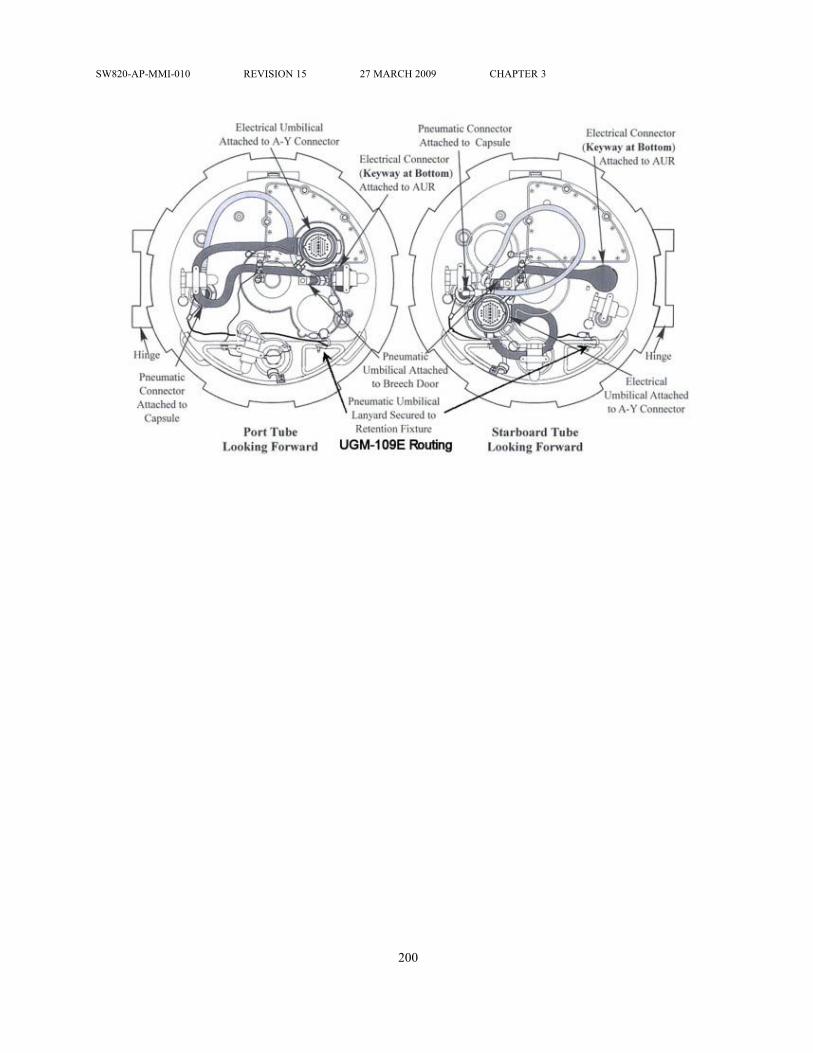
SW820-AP-MMI-010 REVISION 15 27 MARCH 2009 CHAPTER 3
200

SW820-AP-MMI-010 REVISION 15 27 MARCH 2009 CHAPTER 3
Figure 3-2. CLS Electrical Umbilical Routing
201

SW820-AP-MMI-010 REVISION 15 27 MARCH 2009 CHAPTER 3
Figure 3-3. VLS Exhaust Gas Control
202

SW820-AP-MMI-010 REVISION 15 27 MARCH 2009 CHAPTER 3
Table 3-1. Land-Attack TCMCMGS Alignment ModesMODE COMMENT0, Warmup Mode 0 performs the first set of BITs and sequences the CMGS
inertial platform into gyro control. Operations include warmup,loading of operational flight program, initialization, BIT, gyrocaging and gyro spinup. BIT results are contained in the MISSILESTATUS word. If all BITs are passed and gyros have spun up, themode number advances to Mode 1.
1, Standby Mode 1 tests availability to present position and checks to seeif inertial platform is under gyro control. Program will advanceto Mode 2 when present position is available and platform isdetermined to be under gyro control.
2, Course Level During Mode 2, the inertial platform is torqued to level bycomputer program torquing commands. Mode is complete whenthe computed tilt angle and mode time tests are passed.
3, Spare Not used.4, Align Axis#1 Mode 4 performs the first fine alignment phase and is completed
when a series of mode time, computed tilt angle, gyro biaschange and azimuth angle change tests are satisfied. If sufficientmaneuvering occurs in this mode to estimate the platform azimuthangle, Modes 5 and 6 are bypassed and Mode 7 will be enteredat alignment completion.
5, Slue During Mode 5, the platform is slued 90° from its previousorientation by torquing the vertical gyro.
6, Align Axis #2 Mode 6 performs the second fine alignment phase and duplicatesthe Mode 4 alignment. Upon passing of mode completion tests, thealignment process advances to Mode 7.
7, Alignment Complete Mode 7 is used only to indicate that alignment complete tests havebeen passed. The computer program continues to perform the Mode6 alignment until the CMGS is commanded to terminate alignment.When this occurs, the computer program advances to Mode 8.
8, Navigate Mode 8 signals that the CMGS has terminated alignment, and it hasbecome an independent navigator.
203

SW820-AP-MMI-010 REVISION 15 27 MARCH 2009 CHAPTER 4
CHAPTER 4 OPERATIONSSECTION I.
4.1 SCOPE.This chapter discusses TWS operations aboard the various types of launch platforms. Thesediscussions include: brief descriptions of the launch platforms and on board equipment used toload, store and launch weapons; typical weapon onload scenarios; and typical launch operations.Section II discusses TTL launch platforms, procedures and operations. Section III discussesCLS launch platforms, procedures and operations. Section IV discusses VLS launch platforms,procedures and operations.
204

SW820-AP-MMI-010 REVISION 15 27 MARCH 2009 CHAPTER 4
SECTION II. TORPEDO TUBE LAUNCH4.2 LAUNCH PLATFORMS.The TTL TWS is employed aboard SSN 688, SSN 774, and SSN 21 Class submarines. TCMlaunch operations are performed utilizing equipment located in the Attack Center, CombatSystems Electronic Space (CSES) and Torpedo Room. General locations of the complexes areshown in Figure 4-1 "General Locations of SSN Complexes"⇒. The following paragraphsdescribe the major TWS-related TTL systems aboard the submarine. A simplified interfaceblock diagram of submarine TWS-related equipment is shown in Figure 4-2 "SSN/TWS-relatedEquipment TTL Interfaces"⇒.
4.2.1 Submarine Combat System. Submarine Combat Systems (SCS) include the CombatControl System (CCS) and the AN/BSY-1 Combat Control/Acoustic Set (CC/A). SSN 688 Classsubmarines may employ either the CCS or CC/A. Each SCS, supported by the ownship navigationsystem, CSES, Over-the-Horizon (OTH) targeting and the appropriate software programs,provides the necessary power, discretes and data to power up weapons, transmit orders, processand display data, initialize and align the missile guidance set, and initiate weapons launch. Alsoincluded are control and monitoring circuits as well as various firing interlocks.
4.2.2 Combat Systems Electronic Space (CSES). The CSES equipment is shared by both theSCS and the navigation system. Computer software programs, which include the operationalflight program, preplanned land-attack mission/targeting data generated at a shore-based TheaterMission Planning System (TMPS) installation and provided to the submarine prior to deployment,platform alignment data and sequential control commands, are stored on disks in the CSES. Thedata are loaded into computer memory and sent to the missile on command. Missile responsesand status are evaluated by the CSES to provide data for displays on TCM status, Built-In-Test(BIT), checksums and launch countdown.
4.2.3 Navigation Equipment. TOMAHAWK capable submarines are equipped with either theElectrically Suspended Gyro Navigator (ESGN) AN/WSN-3A(V)2 or the Dual Miniature InertialNavigation System (DMINS) AN/WSN-1(V)2. Each system consists of two Inertial MeasuringUnits (IMUs) and one dual-channel Navigation Control Console (NCC). Velocity and attitudedata are generated in raw form by the IMUs and transmitted to the CSES via the NCC. The rawdata are processed by the CSES computers to obtain velocity, attitude and position data and thentransmitted to various ship user subsystems.
4.2.4 Weapon Launch and Pressurization/Vent Equipment. The SSN 688 Class submarineweapon launch equipment consists of a weapon launch console (WLC) flanked by two banksof canted torpedo tubes; two tubes port and two tubes starboard. Also included are four PVCmanifolds (one for each torpedo tube) to control the air which pressurizes the TCM prior tolaunch. Pressurization and torpedo tube pre-launch operations are controlled from the WLC.Figure 4-3 "SSN TTL Pressurization/Vent Control System"⇒ depicts the PVC system.
4.2.5 Weapon Shipping/Unshipping Equipment. Both the SSN 688 and SSN 774 Classsubmarines use a shipping line to ship and unship weapons. On SSN 688 Class submarines, themajor components are a portable topside deck skid, intermediate shipping rails and a shipping
205
SW820-AP-MMI-010 REVISION 15 27 MARCH 2009 CHAPTER 4
tray located in the torpedo room. The weapons, restrained by a shipping harness, are loweredor raised along the shipping line, aft end down, using a chain drive. Figure 4-5 "TTL WeaponShipping, Handling and Stowage Equipment (SSN 688 Class)"⇒ depicts SSN 688 Classsubmarine shipping, handling and stowage equipment. On SSN 774 Class submarines, the majorcomponents are a portable topside deck skid, intermediate and shipping trunk mounted shippingrollers, and a shipping cradle located in the torpedo room. The weapons, restrained by a shippingnose piece and shipping cables, are lowered or raised along the shipping line, forward-end down,using a pier-side crane connected to the shipping cables.
4.2.6 Weapon Handling and Stowage Equipment. Two-level stowage racks are provided aftof the torpedo tubes for stowage of weapons. On the SSN 688 Class, the weapons are supportedby dollies on athwartship tracks and are restrained by lashing straps. On the SSN 774 Class, theweapons are supported in cradles which in turn are supported at each end by an end truss trackand restrained by lashing bands. Transfer of weapons to the torpedo tube, or to any other stowageposition or working space, is accomplished via athwartship transfer mechanisms, vertical hoist(s),pivot mechanisms/trays and loading rammers.
4.3 WEAPON ONLOAD.The supporting submarine tender or shore base removes the weapon from its shipping containerand places the weapon on the topside skid (SSN 688 Class). Subsequent actions to lower theweapon to the torpedo room are depicted in Figure 4-5 "TTL Weapon Shipping, Handling andStowage Equipment (SSN 688 Class)"⇒ for SSN 688 Class submarines. Weapon onload isperformed in accordance with applicable volumes and parts of NAVSEA OD 44979.
4.4 OPERATIONAL CONSTRAINTS/RESTRICTIONS.Tactical employment of a TCM may impose constraints on the operating parameters of thesubmarine and restrictions on the submarine’s tactical flexibility. The following paragraphsidentify the different constraints and methods of alerting the ship’s commanding officer to anoperational constraint or restriction.
4.4.1 Launch Constraints. The launch constraints imposed on the operational parameters ofthe submarine during employment of tactical and exercise variants are described in the applicabletactical employment manuals.
4.4.2 Weapon Mix. Weapon mix will depend on the particular conditions that exist at the timethe decision is made to load torpedo tubes. The SCS is capable of processing a combination ofTOMAHAWK variants, Mk 48 Torpedoes and other defensive systems. Prime considerationfor specific weapon mix is the time required to prepare and launch a TCM, to include the timerequired to recycle the torpedo tube and, when authorized, to eject the capsule.
4.4.3 Alert Messages and Interlocks. Various alert messages and firing interlocks are used towarn operators or inhibit launch when conditions exist that could impact missile performance,endanger the submarine or result in the launch of a dud missile. Firing interlocks may be eithersoftware or hardware interlocks. Prior to permitting activation of the FIRE switch, the submarinefire control system must receive an indication that the following interlocks are closed:
a. WPN IDENT - Indicates that the designated weapon is loaded in torpedo tube
206

SW820-AP-MMI-010 REVISION 15 27 MARCH 2009 CHAPTER 4
b. INPUTS MATCHED - Indicates that all mission data have been transferred to themissile and the CMGS has responded with appropriate MISSILE STATUS and GOODDATA words
c. WITHIN LIMITS - Indicates that speed and depth of the submarine are within limitsd. TUBE READY - Indicates that the torpedo tube outer door is opene. BOOSTER ARMED - Indicates that the rocket motor igniter is armedf. WARHEAD PREARMED - Indicates that the UGM-109A-1 warhead is in prearmed
condition.g. PRESSURE IN BAND - Indicates that missile pressure is between 3.8 - 7.2 psid.
Upon activation of the FIRE switch and indication of MISSILE ENABLED (i.e., batteriesactivated, BIT passed, MISSILE STATUS word good), the fire control system performs a firinginterlock check and closes final interlocks prior to permitting the impulse fire relay to energizeand eject the TCM from the torpedo tube.
4.5 LAND-ATTACK TCM OPERATIONAL SEQUENCE.This paragraph describes typical actions and responses required to launch a land-attack TCM.Primary coverage is given to a normal launch. Abnormal launch conditions and abort proceduresare discussed by highlighting only those events that differ from a normal launch. Typical launchoperations are shown in Figure 4-6 "UGM-109-1 Land-Attack TCM Operational Sequence (7Sheets)"⇒. The figure illustrates the orders given by the ship’s commanding officer, typicalactions taken by equipment operators and typical equipment operations, status displays andmachine decisions. The operational sequence is described in the following paragraphs. Operatingprocedures and checklists, as well as actions to be taken under abnormal conditions, are containedin appropriate volumes and parts of NAVSEA OD 44979.
4.5.1 Weapon Preparation and Tube Loading. Preparation starts with the authorization tolaunch a land-attack TCM. A torpedo tube is made ready for loading. For a UGM-109A, the 4FZSecurity Alarm System is disconnected and the capsule security band unlocked and removed.The weapon serial number is reverified. The missile is then depressurized and moved to theloadline where the slot covers are removed.
4.5.1.1 The loading pole is attached between the rammer and capsule loading button. Upon orderto load tube, the loadline rollers are raised and ramming is commenced. The capsule nose coverand lashing straps are removed as they clear the forward loadline rollers. Ramming is continueduntil the capsule forward guide stud contacts the tube stop bolt. The stop bolt is then rotated to theLOCK position. On a UGM-109A/C/D-1, the capsule latch pins are pulled to allow the capsulelatches to extend and engage the slots in the aft land of the torpedo tube. On a UGM-109E-1, theretention fixture is installed in the torpedo tube and secured to the capsule. The loading pole isremoved. Two shipping nuts are then removed from the missile holdback assemblies.
4.5.1.2 After verifying STOP BOLT LOCKED indication, covers are removed and the electricalumbilical is connected between the breech door Y-connector and the missile and secured to theinside of breech door. The pneumatic umbilical is connected between the breech door penetrator
207

SW820-AP-MMI-010 REVISION 15 27 MARCH 2009 CHAPTER 4
and the capsule and secured to the eyebolt on the inside of the breech door. The breech door isshut and locked.
4.5.2 Weapon Power-Up and Make Ready. Weapon power-up and make ready is initiatedby the weapon control console (WCC) operator in the attack center. The WCC operatoractivates switches to select Land-Attack TOMAHAWK mode, Land-Attack TOMAHAWKPreset Submode and the designated torpedo tube to be used for launch. These selections permitthe WCC operator to monitor the selected tube and any alerts concerning launch. The weaponlaunch control (WLC) operator in the torpedo room positions the designated tube weapon loadedswitch to the assigned missile variant. This action initiates alignment of torpedo room equipmentto the selected weapon and allows verification in the attack center, through displays on equipmentindicators, that the appropriate weapon is loaded in the tube. If such verification can not beobtained, the launch is recycled or aborted.
4.5.2.1 When ordered, FIRING ORDER and MAKE READY ORDERED are input by theattack control console (ACC) operator which permit other operator actions and equipmentresponses to commence in preparation for launch. The mission disk pack is removed from securestorage and mounted on the random access storage set (RASS). The disk pack serial number isentered and the RASS is initialized.
4.5.2.2 The WLC operator positions the designated tube weapon supply switch to POWER ON.WEAPON READY indicators appear on the WCC, ACC and WLC to reflect that the weaponis ready to receive commands. A tube status check is again performed to verify readiness. IfWEAPON READY indicators are not obtained, the launch is recycled or aborted.
4.5.2.3 Positioning the weapon supply switch to POWER ON applies DC MONITOR/RESETPOWER to the PVC system and a PRESSURIZE indicator appears on the WLC. Upon receipt ofthis indicator, the ship 700-psi air isolation valve of the designated tube pressure/vent manifold isopened to supply air to the missile. When missile pressure stabilizes between 3.8 and 7.2 psid,a PRESSURE IN BAND indicator appears on the WLC and the PRESSURIZE indicator goesout. PRESSURE IN BAND, PRESSURIZE and VENT indicators may cycle on and off duringthe preparation for launch due to changes in missile pressure.
4.5.3 Mission Assignment. With RASS initialized, the CMGS is ready to accept missiondata when BALLISTICS SET and CMGS PROGRAMMED are indicated to the WCC operator(CMGS flight program has been transferred to the missile and the missile has responded witha valid Missile Status Word.). The WCC operator changes the submode until Land-AttackTOMAHAWK Evaluation is indicated on the WCC. THEATER, MPS, MISSION and VERIFYcodes are received from the appropriate authority and entered on the WCC. Mission data arethen indicated on the WCC. Mission data are also transferred to the central computer residentmemory. The WCC operator enters the target number and the pre-established waypoints to thattarget are displayed on the WCC. The WCC operator reviews the mission data and approximateflight path to the target and makes route alterations by introducing or deleting waypoints. TheWCC operator then assigns the mission to a designated torpedo tube and a verification that themission is assigned to the correct tube is performed. Once a mission has been assigned, nofurther modifications can be made without resetting the mission and then reentering the mission
208

SW820-AP-MMI-010 REVISION 15 27 MARCH 2009 CHAPTER 4
number and verification code. After assigning the mission, the WCC operator normally selects theLand-Attack TOMAHAWK Preset submode for the remainder of the launch in order to monitortorpedo tube and missile status and any alerts concerning launch.
4.5.3.1 CMGS alignment begins automatically upon completion of a successful upload of theOperational Flight Program (OFP). The mission data are loaded into the CMGS and a course levelis performed, followed by the alignment of axis#1. The inertial platform is then slued 90° andalignment of axis #2 is performed. The two-position alignment technique eliminates the need toperform submarine maneuvers at latitudes below 75°. If the submarine is maneuvering and theCMGS can estimate platform azimuth angle during alignment of axis#1, the slue and alignmentof axis #2 will be bypassed. Launches at latitudes above 75°, however, will require submarinemaneuvers to meet the alignment timeline. Upon completion of alignment, the CMGS willprovide an ALIGNMENT COMPLETE message to the WCC operator.
4.5.3.2 If CMGS computer BIT is not passed, or valid communications can not be establishedor becomes lost with the CMGS computer, an alert message is provided to the WCC operator.To establish or restore communications, a controlled shutdown of the CMGS is performed andmissile electrical power recycled. The normal start-up sequence is then repeated and program loadreattempted. When program load is accomplished, the reprogram command is sent to the CMGS.
4.5.4 Tube Ready. The final steps to launch the missile are making the torpedo tube ready andarming the weapon. Upon receipt of indications that alignment and mission transfer are completeand that inputs match, the ACC operator gives the order to flood the designated torpedo tube.Responding to the order, the WLC operator floods the tube, and when so ordered, equalizestube pressure with ambient sea pressure. Indicators advise operators that the tube is floodedand equalized. When ordered, the ACC operator orders OPEN DOOR for the designated tube.Responding to the order, the WLC operator opens the muzzle door. Indicators advise ACC andWLC operators that the muzzle door is open. When ordered, the WLC operator turns the launchmode switch to EJECT. The ACC operator selects the firing tube and a NEXT indicator appears.
4.5.5 Rocket Motor Arming. When ordered, the booster armed and warhead arm supplykey-lock (UGM- 109A only) switches are activated by the ACC operator for the designated tube.BOOSTER ARMED indicators on the ACC and WLC advise operators of successful armingof the rocket motor. If indicators do not reflect that the rocket motor is armed, the launch isrecycled or aborted.
4.5.6 Warhead Prearming (UGM-109A only). When ordered, the warhead arm switch on theACC is activated for the designated tube. After approximately 24 to 40 seconds, WARHEADARMED indicators on the ACC and WLC will advise operators that the warhead has beensuccessfully prearmed.
4.5.7 Weapon Firing. With INTERLOCKS CLOSED indicated and firing status ready, theorder is given to the ACC operator to position the STANDBY/FIRE switch to STANDBY.Upon order, the switch is then positioned to FIRE and held until the FIRE indicator is present.Subsequent actions occur automatically. The missile batteries activate and missile essentialbusses are isolated. The CMGS performs a status check using battery power and, if successful,sends a MISSILE ENABLED signal. With the closing of final interlocks, the impulse fire
209

SW820-AP-MMI-010 REVISION 15 27 MARCH 2009 CHAPTER 4
relay energizes, the stop bolt rolls, the electrical umbilical deadfaces, and the tube fires. Uponfiring, TUBE FIRED indicators on the ACC and WLC advise operators that the tube has beensuccessfully fired. If indicators reflect that the tube was not successfully fired, the launch isaborted in accordance with NAVSEA OD 44979.
4.6 POST-LAUNCH OPERATIONS.
The post-launch operational sequence begins after the missile has been launched from the torpedotube. Operations consist of those evolutions to either eject the capsule or return the capsule to thestowage racks. The operations also include resetting the tube if required, and securing the torpedotube. A typical post-launch sequence is briefly described in the following paragraphs. Post-launchoperations are preformed in accordance with NAVSEA OD 44979.
4.6.1 Tube Reset. If the WLC indicator continues to show TUBE FIRED at the completion ofmissile launch, the WLC operator takes action to reset the tube and close the outer door.
4.6.2 Capsule Ejection. (UGM-109A/C/D-1) When ordered to eject capsule, the WLC operatorpositions the missile interrupter switch to MANUAL and the tube stop to LOCK. The WLCoperator then activates the switch to route ship 700-psi air to the capsule. Upon application of airpressure, the capsule sleeve moves forward, unlocking the capsule latches. Continued movementof the capsule sleeve retracts the capsule latches and closes the flow slots. With the closing of theflow slots, the weapon supply switch on the WLC is turned to OFF.
(UGM-109E-1) When ordered to eject capsule, the WLC operator shall unload the capsule fromthe torpedo tube in accordance with NAVSEA OD 44979. The capsule nose cover shall bere-installed. The AUR will then be loaded back into the torpedo tube.
4.6.2.1 When ordered, the ACC operator orders OPEN DOOR. Responding to the order, theWLC operator opens the muzzle door. WLC and ACC indicators advise the operators that thetube is ready to eject the capsule. On order, the tube is fired and the capsule ejected. If indicatorsshow that the tube did not fire, operators refer to NAVSEA OD 44979 for further guidance.
4.6.2.2 Upon receipt of indicators that the tube successfully fired, the WLC operator closes themuzzle door, turns the weapon loaded switch to OFF, secures the ship 700-psi air isolation valveto the pressure/vent manifold, and drains the tube. After the tube is drained, the breech door isopened. The umbilicals and inside of the breech door are rinsed with fresh water to remove saltwater residue, and then dried. The umbilicals are then disconnected and removed, and the tube issecured using procedures contained in NAVSEA OD 44979.
4.6.3 Capsule Return to Stowage. Upon order to stow capsule, the WLC operator turns theweapon supply and weapon loaded switches to OFF, secures the ship 700-psi air isolation valve tothe pressure/vent manifold and drains the tube. The breech door is then opened and the umbilicals,the inside of the breech door and the aft face of the capsule are rinsed with fresh water to removesalt water residue, and dried. The umbilicals are then disconnected and removed. The capsulelatches are manually retracted by pressing and holding their spring-loaded plungers; then liftingthe latches and securing them with the pins provided. The capsule is removed from the tube using
210

SW820-AP-MMI-010 REVISION 15 27 MARCH 2009 CHAPTER 4
procedures contained in NAVSEA OD 44979 rinsed with fresh water, dried, covers installed andthe capsule is then moved and secured to a stowage position.
4.7 LAND-ATTACK TCM CASUALTY MODE.There is no casualty mode for land-attack TCM variants.
211

SW820-AP-MMI-010 REVISION 15 27 MARCH 2009 CHAPTER 4
SECTION III. CAPSULE LAUNCHING SYSTEM4.8 LAUNCH PLATFORM.The TWS provides selected SSN-688 Class, SSN-774 Class and SSGN-726 Class submarineswith the capability to carry, target, and launch TCMs against enemy land targets. TCM launchoperations are performed aboard the submarine utilizing equipment located in the Attack Center,Combat Systems Electronic Space (CSES) and Vertical Launch Center. General locations ofthe complexes are shown in Figure 4-8 "General Locations of SSN 688 Class SubmarineComplexes"⇒. The following paragraphs describe the major TWS-related CLS systems aboardthe submarine. A simplified interface block diagram of TWS-related equipment aboard thesubmarine is shown in figure 4-9 "SSN 688 Class Submarine TWS-related Equipment Interfaces(2 Sheets)"⇒.
4.8.1 Submarine Combat System (SCS). The SCS include the Combat Control System(CCS) and the AN/BSY-1 Combat Control/Acoustic Set (CC/A). SSN 688 Class submarinesmay employ either the CCS or CC/A. Each SCS, supported by the ownship navigation system,CSES, Over-the-Horizon targeting (OTH-T) and the appropriate software programs, provides thenecessary power, discretes and data to power up weapons, transmit orders, process and displaydata, initialize and align the missile guidance set, and initiate weapons launch. Also included arecontrol and monitoring circuits as well as various firing interlocks.
4.8.2 Combat Systems Electronic Space (CSES). The CSES equipment is shared by both theSCS and the navigation system. Computer software programs, which include the operationalflight program, preplanned land-attack mission/targeting data generated at a shore-based TheaterMission Planning System (TMPS) installation and provided to the submarine prior to deployment,platform alignment data and sequential control commands, are stored on disks in the CSES. Thedata are loaded into computer memory and sent to the missile on command. Missile responsesand status are evaluated by the CSES to provide data for displays on TCM status, Built-In-Test(BIT), checksums and launch countdown.
4.8.3 Navigation System. SSN/VLS capable submarines are equipped with the ElectricallySuspended Gyro Navigator (ESGN) AN/WSN-3A(V)2. The system consists of two InertialMeasuring Units (IMUs) and one dual-channel Navigation Control Console (NCC). Velocity andattitude data are generated in raw form by the IMUs and transmitted to the CSES via the NCC.The raw data are processed by the CSES computers to obtain velocity, attitude and position dataand then transmitted to the various ship user subsystems.
4.8.4 Weapon Launch System. The weapon launch system consists of the missile tubeassembly and the various ship systems which operate the missile tube assembly during stowageand launch operations. The following paragraphs describe the components of the weapon launchsystem.
4.8.4.1 Missile Tube Assembly. The missile tube assembly (Figure 4-10 "SSN 688 ClassSubmarine Missile Tube Assembly"⇒) houses and physically protects the weapon in themissile tube. The assembly consists of the missile tube, hatch and linkage gear, and interfacesto operate the assembly. Ship system interfaces include connections for the flood and drain and
212

SW820-AP-MMI-010 REVISION 15 27 MARCH 2009 CHAPTER 4
pressurization/vent systems. AUR interfaces provide shock mitigation and alignment of theAUR as well as a means to pressurize the AUR in the missile tube. Missile tubes are topped byhatches that are individually operated by outboard hydraulic rotary actuators and are locked by anover-center toggle linkage mechanism with locking further enhanced by a device to assure thathatches do not inadvertently open when adjacent tubes are subjected to launch pressure.
4.8.4.2 Hydraulic System. The hydraulic system (Figure 4-11 "SSN 688 Class SubmarineHydraulic System"⇒) provides power to actuate flood and drain system valves and missiletube hatches.
4.8.4.3 Pressurization/Vent System. The pressurization/vent system (Figure 4-12 "SSN 688Class Submarine Pressurization/Vent System"⇒) replenishes the AUR internal atmosphereduring stowage and pressurizes or vents the AUR to maintain internal pressure within a specifiedrange of positive pressure over the underhatch volume pressure prior to launch using 700 psigship service air.
4.8.4.4 Flood and Drain System. The flood and drain system (Figure 4-13 "SSN 688 ClassSubmarine Flood and Drain System"⇒) floods and equalizes the missile tube underhatch volumeto sea pressure so that the hatch can be opened, drains the underhatch volume to remove waterand allows this volume to be maintained at submarine internal ambient pressure.
4.8.4.5 Missile Tube Control System. The missile tube control system (Figure 4-14 "SSN 688Class Submarine Missile Tube Control System"⇒) contains the controls, indicators, and interlockcircuitry necessary to ready the missile tubes for launch and to monitor missile tube operation.The system also provides all of the interfaces between the ship systems and the SCS.
4.9 ONLOAD AND OFFLOAD.The following paragraphs provide general information regarding preparation for, and onloadand offload of weapons, as well as offload of a spent CLS. Various volumes of NAVSEAOD 44979 contain specific procedures to be used by SSN personnel. Technical manualSW820-AD-WHS-010/UGM-109-2 contains specific procedures for submarine tender and shorebased personnel supporting SSNs. For SSGN Class procedures refer to NAVSEA OD 64501 andSW820-AD-WHS-040/UGM-109-2.
4.9.1 Onload. Submarine onload begins when the submarine arrives at a designated shorebase activity or supporting submarine tender to receive a complement of weapons. Wind andsea motion, which affect the submarine’s position and movement, are factors in determiningthe feasibility of loading operations. To prevent damage to the missile, ship, or equipment,it is recommended that weapons not be onloaded or offloaded if roll exceeds 3 degrees or pitchexceeds 1/2 degree, and winds exceed 30 knots. The submarine tender/shore base loadingsupervisor and the submarine’s commanding officer will determine if conditions are satisfactoryprior to commencing onload. Prior to onload, the security system is neutralized for each missiletube to be loaded; flood and drain system and pressure/vent system operability are verified at theVLC; and SCS operability is verified through operator conducted system diagnostics. Duringloading, responsibility for all operations is shared between the submarine’s commanding officerand the submarine tender/shore base loading supervisor. All actions involving ship system
213

SW820-AP-MMI-010 REVISION 15 27 MARCH 2009 CHAPTER 4
preparation are the responsibility of the submarine’s commanding officer. His permission isrequired prior to commencing loading operations. His designated representative is responsiblefor weapon handling operations and ensures that a weapon transfer inspection is conducted.Upon completion of submarine preparation, responsibility for loading transfers to the submarinetender/shore base loading supervisor. The submarine crew conducts the final hookup andcloseout of the missile tube upon disconnect and removal of the loading equipment from thesubmarine. The following paragraphs provide a general overview of procedures used duringloading operations. For purposes of illustration, loading of a generic weapon into one missiletube is discussed. There are some minor differences in loading procedures among AURs, AURSimulator Volumetric Shapes and ballast cans which are not discussed. For multiple loadings,the procedures are the same except that multiple actions may be occurring simultaneously toprepare missile tubes and weapons. Additionally, loading equipment is moved from missiletube to missile tube until the full complement of weapons is aboard the submarine. Similarly,post-loadout is accomplished on a tube by tube basis until full closeout is accomplished. Onloadterminates when the submarine has received its scheduled complement, final hookup has beenaccomplished, all loading equipment has been removed, missile tube hatches are closed andsecured, and ship system equipment has been activated.
4.9.1.1 Prepare Missile Tube and Ship Systems. After supporting submarine tender/shorebase personnel have erected the loading platform (Figure 4-15 "Loading Platform Installed"⇒).submarine personnel prepare the missile tube and ship systems for onload. The missile tube hatchis opened and gagged (Figure 4-16 "SSN 688 Class Submarine Missile Tube Equipment"⇒). andthe missile tube is visually inspected to ensure it is free of potential contaminants. Contaminants,if present, will damage the lip seal on an AUR or o-ring on an AUR Volumetric Shape/Simulatorduring loading. The muzzle face protective cover and the missile tube muzzle hatch andmagnet protective cover are installed (Figure 4-16 "SSN 688 Class Submarine Missile TubeEquipment"⇒). For the AUR Volumetric Shape/Simulator onload, the mylar O-ring protectivesleeve assembly is also installed. Special procedures like direct tube to tube transfer of AURson the same submarine or between different submarines may utilize lip seal protective covers(fabricated from split garden hose or equivalent) or a lip seal protective sleeve (fabricated fromvarious sheet materials). The counterbore cover is installed to prevent personnel, tools, waterand debris from entering the empty missile tube. The Environmental Monitoring Sensor (EMS)pressure and temperature ambients are checked, and a leak test performed. SCS circuits arechecked using the All-Up-Round Electronic Simulator (AURES). The accuracy of the differentialpressure transducer is verified and the pressurize/vent (P/V) plug is removed and stowed. Thecounterbore cover is removed.
4.9.1.2 Install Loading Equipment. After the missile tube and ship systems have beenprepared for loading, submarine tender/shore base personnel install the loading equipment aboardthe submarine. This includes the Installation Guide Assembly Mk 116, Hydraulic Power Unit(HPU) Mk 8, Missile Tube Extension Loader (MTEL) Mk 23 and the MTEL Safety Cover. Theinstallation guide is installed on the missile tube inner shoulder to assist in centering the MTELover the missile tube. The MTEL is lowered over the missile tube, maneuvered to align itsguide holes with the missile tube pins, and bolted to the muzzle face. The installation guide isthen removed. The MTEL safety cover is installed over the MTEL mouth to prevent objects from
214

SW820-AP-MMI-010 REVISION 15 27 MARCH 2009 CHAPTER 4
falling into the open missile tube. The HPU is positioned on the loading platform and connectedto the electrical source aboard the submarine. Hoses are connected between the HPU and theMTEL. A check is made to insure the centering guides and the insertion pin stop-plates are inthe correct position on the MTEL
4.9.1.3 Prepare Weapon. As the missile tube and ship systems are being prepared for loadingand loading equipment is being installed, submarine tender/shore base personnel prepare theweapon for loading. After opening the Shipping and Storage Skid Mk 30, two trunnions ortrunnion bearing assemblies are installed in the weapon to allow vertical uprighting with eitherthe Tilt Fixture, Mk 23 Mod 0 with Kit B, or a Shipping and Storage Skid Mk 30 that hasbeen rigged for uprighting. The weapon is removed from the skid and placed in the uprightingequipment being used where, if not previously performed, a pressure check and inspection, toinclude rocket motor safe/armed and weapon configuration tests, are performed. Interface supportand elastomer loading guard pads as well as the upper flange grooves are greased to facilitateloading the weapon into the missile tube. The forward section of the weapon is depressurizedand the Closure Protective Cover (CPC) is replaced with the Capsule Loading Cover (CLC). Theannular space vent plug is removed and stowed. Two lip seals are then greased and carefullyinstalled into the upper flange grooves. The lifting adapter is then attached to upright the weaponto the vertical position.
4.9.1.4 Load Weapon in Missile Tube. The weapon is uprighted about the trunnions ortrunnion bearing assemblies and lifted off the Mk 23 fixture (Figure 4-34 "Tilt Fixture Mk 23Mod 0 with Kit B"⇒) or uprighting skid (Figure 4-17 "CLS Weapon Onload"⇒). The trunnionsor trunnion bearing assemblies are removed and the weapon is lifted over the MTEL and alignedfor insertion into the missile tube. The MTEL safety cover is removed. The weapon is loweredinto the MTEL until the bellyband and the moisture and dust plug can be sequentially removed.The MTEL centering guides are released to allow the flange to pass, permitting the weapon to belowered until the lifting adapter is above the bellmouth. The lifting adapter arm is then pinnedin the vertical position and the weapon is further lowered until the lifting adapter insertion pinsrest on the MTEL stop plates (Figure 4-18 "CLS Weapon Seating in Missile Tube"⇒). Seatingthe weapon in the missile tube is accomplished hydraulically using the HPU. The lifting adapterarm is disconnected from the crane and the MTEL hydraulic cylinders are connected to thelifting adapter insertion pins. The hydraulic cylinders are extended using the HPU until theweapon seats in the missile tube.
4.9.1.5 Remove Loading Equipment. After the AUR has been fully seated in the missile tube,the MTEL hydraulic cylinders are disconnected from the lifting adapter insertion pins. Theinsertion pins are inserted into the lifting adapter and the MTEL hydraulic cylinders are then fullyretracted. The HPU is disconnected from the MTEL and the MTEL unbolted from the muzzleface and removed from the deck. The lifting adapter is unbolted and removed from the weaponwhich signifies completion of the loading sequence and final hookup and testing becomes theresponsibility of submarine personnel.
4.9.1.6 Post-Loadout. Post-loadout involves connecting the weapon to the ship systemsthrough missile tube interfaces (Figure 4-19 "Secure CLS Weapon in Missile Tube"⇒). Theumbilical cable connector is connected to the missile tube umbilical connector. Eight retention
215

SW820-AP-MMI-010 REVISION 15 27 MARCH 2009 CHAPTER 4
segments are installed to restrain the CLS in the missile tube at launch. Umbilical cable bracketsare connected to the retention segments to restrain the umbilical. The SCS, missile tube, andweapon are then tested to ensure operability. The annular space vent is plugged and the P/Vsensing line connected to the pressure transducer in the missile tube. A leak test at the missiletube hatch opening is conducted and the underhatch area cleaned. The CLC is removed and thecapsule closure is inspected to ensure no damage occurred during loading. The missile tube hatchand fairing are then closed and the loading platform removed.
4.9.1.7 SSGN Onload Overview. The following paragraphs provide a brief description of theunique aspects of onloading the Tomahawk onboard a SSGN-726 Class submarine.
4.9.1.8 AUR Onload Sequence. An onload sequence begins with staging and preparing thework platform (Figure 4-4 "MTEL Work Platforms"⇒) onto the MTEL, attaching the MTELadapter (Figure 4-7 "MTEL With MTEL Adapter Installed"⇒) onto the MTEL, and attachingthe lifting adapter extension (Figure 4-21 "Lifting Adapter and Extension"⇒) onto the liftingadapter. The MTEL work platform, the MTEL adapter and the lifting adapter extension aresupport equipment unique to SSGN.
4.9.1.9 Organizational-Level Preparations. The submarine crew opens the missile tubehatch providing access to the Multiple All-Up-Round Canister (MAC) (Figure 4-33 "MultipleAll-Up-Round Canister (Fully Loaded)"⇒) and its individual AUR cells, and tags out thehydraulic system. The appropriate AUR cells are inspected for dirt, debris or foreign material thatwill damage lip seals during loading, and the area is cleaned as required.
4.9.1.10 Installing Loading Equipment. The HPU is transferred and secured to the SSGNwork area. There are two different MTEL Adapters and each must be used in the appropriateAUR cells. The 7124601-003 Adapter is used with MAC cells A, C, E, and G. The 7124601-004Adapter is used with MAC cells B, D and F (Figure 4-35 "Multiple All-Up-Round CanisterMTEL Orientation"⇒). The prepared MTEL/MTEL Adapter is lowered onto the AUR cell andoriented with the large and small alignment pins temporarily placed in the MAC top plate. TheMTEL/MTEL Adapter is secured to the MAC with four bolts. The hydraulic hoses from the HPUare connected to the manifold on the MTEL.
4.9.1.11 Uprighting and Inserting. Procedures to upright the AUR are similar to the SSN Classwith the exception of installing the lifting adapter extension. Inserting the AUR is essentiallythe same as for the SSN Class as well, with the MTEL adapter providing an interface betweenthe existing MTEL design and the MAC top plate. The additional height of the MTEL adapterrequires the lifting adapter be attached to the AUR with an extension of equal height.
The MTEL adapter is outfitted with a guide ring. The guide ring can be rotated to the open or shutposition to engage or disengage the guide shoes. The guide shoes perform the same function asthe MTEL centering guides, which is to assist in keeping the AUR in the center of the cell duringloading and offloading operations.
4.9.1.12 Removing Loading Equipment. The MTEL/Adapter is unbolted from the MAC topplate and removed. The lifting adapter/extension is unbolted from the capsule upper flange andremoved. The HPU is disconnected from the electrical power source and removed.
216

SW820-AP-MMI-010 REVISION 15 27 MARCH 2009 CHAPTER 4
4.9.1.13 Organizational-Level Closeout Operations. Topside personnel connect thepressure/vent sensing line and install the eight retention segments to secure the AUR in the AURcell. Topside personnel mate the AUR upper umbilical cable connector to the MAC umbilicalcable stowage receptacle. Inside the MAC, the crew connects the AUR ground strap, moves theP1130 connector to the stowage position of the aft cover, and mates the MAC umbilical cable tothe J1130 connector (Figure 4-36 "AUR Aft Cover Viewed in MAC"⇒). Each AUR requiresone MAC umbilical to be connected to the J1130 connector. A bubble test is performed on theinstalled AUR to check for leaks at the MAC top plate.
4.9.2 Offload. Submarine offload begins when the submarine arrives at a designated shorebase activity or supporting submarine tender to discharge a complement of weapons or spentCLSs. Wind and sea motion, which affect the submarine’s position and movement, are factorsin determining the feasibility of offload operations. To prevent damage to the missile, ship,or equipment, it is recommended that weapons not be offloaded if roll exceeds 3 degrees orpitch exceeds 1/2 degree, and winds exceed 30 knots. The submarine tender/shore base loadingsupervisor and the submarine’s commanding officer will determine if conditions are satisfactoryprior to commencing offload. Prior to offload, ship systems are neutralized for each missile tube tobe offloaded. During offload, responsibility for all operations is shared between the submarine’scommanding officer and the submarine tender/shore base loading supervisor. All actions involvingship system and weapon preparation are the responsibility of the submarine’s commanding officer.His permission is required prior to commencing offload operations. His designated representativeis responsible for weapon handling operations and ensures that a weapon transfer inspection isconducted. Upon completion of submarine and weapon preparation, responsibility for offloadtransfers to the submarine tender/shore base. The following paragraphs provide a generaloverview of procedures used during offload operations. For purposes of illustration, offload of ageneric weapon from one missile tube is discussed. There are some minor differences in offloadprocedures among AURs, AUR Simulator Volumetric Shapes, ballast cans and spent CLSs whichare not discussed. For multiple offloads, the procedures are the same except that multiple actionsmay be occurring simultaneously to prepare missile tubes and weapons. Additionally, loadingequipment is moved from missile tube to missile tube until the full complement of weapons isoffloaded from the submarine. Similarly, post-offload procedures are accomplished on a tube bytube basis until full closeout is accomplished. Offload terminates when all weapons scheduled foroffload have been removed from the submarine and all loading equipment has been removed
4.9.2.1 Prepare Missile Tube and Ship Systems. Initially, the SCS must be disengaged fromthose missile tubes containing weapons to be offloaded. After the SCS has been disengagedfrom those missile tubes to be offloaded and the loading platform (Figure 4-15 "LoadingPlatform Installed"⇒) installed by supporting submarine tender/shore base personnel, the firstmissile tube hatch is opened and gagged (Figure 4-16 "SSN 688 Class Submarine Missile TubeEquipment"⇒). The muzzle face protective cover, the missile tube muzzle hatch and magneticprotective cover and the EMS protective cover are installed to protect submarine personnel andequipment while preparing AUR weapons for removal.
4.9.2.2 Prepare Spent CLS for Offload. In addition to those above tasks to be performed toprepare for weapon offload, reflood water and residue must be removed from a spent CLS prior
217

SW820-AP-MMI-010 REVISION 15 27 MARCH 2009 CHAPTER 4
removing it from the missile tube. Submarine tender/shore base personnel pump approximatelyhalf of the reflood water in the spent CLS into a holding tank using a submersible pump. Thesubmarine crew then performs a P/V piping blow-down to ensure reflood water is removed. Theupper tube and muzzle hatch areas are then flushed with fresh water and all residual reflood wateris pumped from the spent CLS. Remaining residue and by-products are cleared from above theCLS in order to attach the lifting adapter. Additionally, egress of the TCM from the CLS causesthe diaphragm to rupture leaving residue which must be removed to permit attachment of the CLCand to secure the umbilical cable to the cover.
4.9.2.3 Prepare Weapon for Offload. Once the missile tube has been prepared, the submarinecrew prepares the weapon for offload. The CLC is installed. The umbilical cable connector isdisconnected, the connector protective cap installed, and the connector is secured to the CLC.Umbilical cable clamps, retention segments and the annular space vent plug are then removed.A protective shield is installed on the umbilical to prevent contact with the missile tube anddamage to the umbilical.
4.9.2.4 Install Offload Equipment. Submarine tender/shore base personnel connect the liftingadapter to the weapon. The MTEL is positioned, and secured over the missile tube. The HPU ispositioned on the loading platform and connected to the electrical source aboard the submarineand to the MTEL cylinders. The lifting adapter insertion pins are installed and the MTELhydraulic cylinders are connected to the insertion pins.
4.9.2.5 Remove Weapon from Missile Tube. With the MTEL cylinders attached to the liftingadapter insertion pins, the HPU is energized causing the hydraulic cylinders to retract therebyextracting the weapon from its seated position in the missile tube. The weapon is positioned onthe stop plates and the hydraulic cylinders are detached from the insertion pins. A crane hook isattached to the lifting adapter arm to withdraw the weapon. As the weapon is raised, the insertionpins are retracted, the moisture and dust plug is installed, and the bellyband and tag lines areattached. The weapon is fully extracted from the missile tube, lifted clear of the submarine andtransferred to the tender or dockside where trunnions or trunnion bearing assemblies are installed.The weapon is positioned on the Tilt Fixture, Mk 23 Mod 0 with Kit B, or on a MK 30 skid riggedwith a Mk 26 Uprighting Fixture.
4.9.2.6 Remove Offload Equipment. After the weapon has been removed from the missiletube, the offload equipment is removed from the submarine or moved to another missile tube.The MTEL centering guides are disengaged, the HPU/MTEL connection is severed and thehydraulic cylinders are stowed on the MTEL. After detaching the MTEL from the missile tube,the MTEL is removed.
4.9.2.7 Secure Missile Tube and Ship Systems after Weapon Offload. After the offloadingequipment has been removed from the missile tube, the submarine crew secures the missile tubeand ship systems. The crew installs the missile tube counterbore cover, the P/V port plug, and themissile tube umbilical security cap. The missile tube muzzle hatch protective cover, muzzle faceprotective cover, fairing, cofferdam, and counterbore cover are removed. The missile tube hatchis ungagged and the hatch is closed. Flood and drain, pressurization/vent and security systems arethen energized to return the submarine to normal operations. The loading platform is removed.
218

SW820-AP-MMI-010 REVISION 15 27 MARCH 2009 CHAPTER 4
4.9.2.8 Post-Launch P/V Refurbishment after Spent CLS Offload. After the offloadequipment has been removed from the missile tube, the submarine crew conducts post-launch P/Vrefurbishment. The P/V valve is disassembled, cleaned, and reinstalled. Differential transducerlines are cleaned and the transducer is checked and tested. P/V piping is flushed, dried and testedfor serviceability. Upon completion of the refurbishment, the P/V plug is reinstalled.
4.9.2.9 Post-Launch Missile Tube Refurbishment after Spent CLS Offload. Launching aTCM and exposure to sea water during the launch may cause minor damage to the missile tubenecessitating post-launch missile tube refurbishment. The submarine crew removes the missiletube counterbore cover, inspects the interior of the missile tube and performs, or arranges for,missile tube maintenance depending on the complexity of repairs required.
4.9.2.10 SSGN Offload Overview. The following paragraphs describe unique aspects ofoffloading the Tomahawk from a SSGN-726 Class submarine. Primary elements unique tooffloading from the SSGN platform are the location of the umbilical for disconnection bysubmarine personnel, and the requirements for the MTEL work platform, MTEL adapter, andlifting adapter extension.
As discussed in the SSGN onload overview, there are two MTEL adapters each of which must beused in the appropriate AUR cells. The 7124601-003 Adapter is used with MAC cells A, C, E andG. The 7124601-004 Adapter is used with MAC cells B, D and F.
Similar to the MTEL centering guides, the guide ring of the MTEL adapter is rotated to theshut position to engage the guide shoes and assist in keeping the AUR in the center of the cellduring offload.
4.10 OPERATIONAL CONSTRAINTS/RESTRICTIONS.Tactical employment of the TCM imposes a number of constraints on the operating parameters ofthe submarine. The constraints imposed during tactical launch operations of the TOMAHAWKCruise Missile are provided in applicable tactical publications. Employment also placesrestrictions on the submarine’s tactical flexibility which are described in Operating Guidelines,tactical employment manuals and operation manuals.
4.10.1 Weapon Mix. Weapon mix will depend on the particular conditions that exist at thetime the decision is made to prepare weapons for launch. The SCS is capable of processing acombination of land-attack TCM variants for single or salvo launch from vertical missile tubes,as well as a combination of land-attack TCM variants, Mk 48 Torpedoes and other defensivesystems for launch from torpedo tubes. Prime consideration for selecting a specific weapon forlaunch should be the time required to prepare and launch a single TCM or, in the case of salvofire, the time required to prepare and launch multiple TCMs.
4.10.2 Alert Messages and Interlocks. Various alert messages and firing interlocks are used towarn operators or inhibit launch when conditions exist that could impact missile performance,endanger the submarine or result in the launch of a dud missile. Firing interlocks may be eithersoftware or hardware interlocks. Prior to permitting activation of the FIRE switch, the fire controlsystem must receive an indication that the following interlocks are closed:
219

SW820-AP-MMI-010 REVISION 15 27 MARCH 2009 CHAPTER 4
a. OPERATIONAL FLIGHT PROGRAM TRANSFERRED - Indicates that the flightprogram has been successfully transferred to the missile.
b. MISSILE ALIGNED - Indicates that the CMGS inertial platform relative to thesubmarine’s inertial reference system has been aligned.
c. MISSION DATA TRANSFERRED - Indicates that all data relative to the mission havebeen transferred to the missile.
d. WITHIN LIMITS - Indicates that speed and depth of the submarine are within limits.e. INPUTS MATCHED - Indicates that the CMGS has responded with good MISSILE
STATUS, missile presetting is complete and launch constraints are satisfied,f. TUBE IN ACTIVE FIRING SEQUENCE - Indicates that the proper tube has been
selected and sequenced, all controls have been positioned and all indicators are go.g. TUBE READY - Indicates that the underhatch volume has been flooded and the
pressurization/vent control valve is closed.h. CAPSULE/BOOSTER PREARMED - Indicated that the capsule and rocket motor are
in the prearmed position.
Upon activation of the FIRE switch and indication of MISSILE ENABLED (i.e., , hatch open,booster armed, capsule armed, batteries activated, BIT passed, MISSILE STATUS word good),the fire control system closes firing interlocks prior to permitting the coded charge and launchsignals to be sent to the CLS.
4.11 LAND-ATTACK TCM OPERATIONAL SEQUENCE.This paragraph describes typical actions and responses required to launch a land-attack TCM.Primary coverage is given to normal launch of a single weapon. For salvo launch, the operationalsteps for a single launch are sequentially accomplished for each weapon selected for launch.Abnormal launch conditions and abort procedures are discussed by highlighting only thoseevents that differ from a normal launch. Typical launch operations are shown in Figure 4-20"UGM-109-2 Land-Attack TCM Operational Sequence (10 Sheets)"⇒. The figure illustrates theorders given by the ship’s commanding officer, typical actions taken by equipment operators andtypical equipment operations, status displays and machine decisions. The operational sequenceis described in the following paragraphs. For a full discussion of operating procedures andchecklists, as well as actions to be taken under abnormal conditions, refer to the appropriatevolumes and parts of NAVSEA OD 44979.
4.11.1 Weapon Preparation. Preparation for launch commences with the authorization fromthe commanding officer. He will issue the necessary make ready command for a single or salvolaunch. Based on that command, the MAKE READY command is issued and the appropriateland-attack weapon for the mission is selected. To verify the correct missile has been selected andto permit weapon power-up, the Weapon Supply Switch is placed in the IDENT position. Shoulda weapon conflict result from CM IDENT POWER application, an ID ERROR will be displayedand all relays to the weapon will remain closed.
4.11.2 Weapon Power-Up and Make Ready. When the correct designator is reflected, theMissile Power keyswitch is placed in the ENABLE position and the Weapon Supply Switch is
220

SW820-AP-MMI-010 REVISION 15 27 MARCH 2009 CHAPTER 4
moved from IDENT to ON. This permits MONITOR/RESET POWER and CAPSULE POWERto flow to the missile and CLS respectively so the SCS can transmit commands, receive responses,and open relay circuitry for missile OPERATE POWER. Additionally, activation of the switchespermits the flow of REM BATTERY HEATER POWER to exercise weapons. Weapon responsesare monitored to ensure that BOOSTER SAFE and CAPSULE SAFE indicators show that theweapon is in a safe status. If a BOOSTER ARMED or CAPSULE ARMED indication exists,or there is no condition status indicated, the launch is aborted.
4.11.3 Mission Assignment. The appropriate mission disk pack is removed from secure storageand mounted on the random access storage set (RASS). The disk pack serial number is enteredand the RASS initialized. With RASS initialized, the Cruise Missile Guidance Set (CMGS) isready to accept mission data when BALLISTICS SET and CMGS PROGRAMMED are indicatedto the Weapon Control Console (WCC) operator (CMGS flight program has been transferred tothe missile and the missile has responded with a valid Missile Status Word.). The WCC operatorchanges the submode until Land-Attack TOMAHAWK Evaluation is indicated on the WCC.THEATER, MPS, MISSION and VERIFY codes are received from the appropriate authorityand entered on the WCC. Mission data are then indicated on the WCC. Mission data are alsotransferred to the central computer resident memory. The WCC operator enters the target numberand the pre-established waypoints to that target are displayed on the WCC. The WCC operatorreviews the mission data and approximate flight path to the target and makes route alterations byintroducing or deleting waypoints. The WCC operator then assigns the mission to the designatedmissile tube and a verification that the mission is assigned to the correct tube is performed. Oncea mission has been assigned, no further modifications can be made without resetting the missionand then reentering the mission number and verification code. After assigning the mission, theWCC operator normally selects the Land-Attack TOMAHAWK Preset submode for the remainderof the launch in order to monitor tube and missile status and any alerts concerning launch.
4.11.3.1 CMGS alignment begins automatically upon completion of a successful upload of theOperational Flight Program (OFP). A two-position alignment technique eliminates the need toperform submarine maneuvers at latitudes below 75°. Launches at latitudes above 75°, however,will require submarine maneuvers to meet the alignment timeline. Upon completion of alignment,the CMGS will provide an ALIGNMENT COMPLETE message to the WCC operator.
4.11.3.2 If CMGS computer built-in test (BIT) is not passed, or valid communication can notbe established or becomes lost with the CMGS computer, an alert message is provided to theWCC operator. To establish or restore communications, a controlled shutdown of the CMGS isperformed and missile electrical power recycled. The normal start-up sequence is then repeatedand program load reattempted. When program load is accomplished, the reprogram commandis sent to the CMGS.
4.11.4 Rocket Motor/Capsule Prearm. When proper authorization is given, the BOOSTERARM and CAPSULE ARM switches are activated to prearm the rocket motor and capsulerespectively.
4.11.5 Tube Ready. When the WCC display indicates INPUTS MATCHED YES, and whenproper authorization is given, the READY TO FLOOD pushbutton at the Vertical Launch Console
221

SW820-AP-MMI-010 REVISION 15 27 MARCH 2009 CHAPTER 4
(VLC) is depressed and the FLOOD/DRAIN valve opened. The Hatch Control Switch must bein REMOTE. FLOOD/DRAIN VALVE OPEN and EQUALIZE indicators illuminate, and thePRESSURE IN BAND indicator remains illuminated. Consoles are continuously monitored toensure that all systems are operational. Any anomaly will be displayed on the WCC as a systemsalert or mode message which must be resolved prior to proceeding with the launch.
4.11.6 Weapon Firing. When the STANDBY ENABLE is displayed, the STANDBY switch isactivated. A STANDBY indicator illuminates at the VLC which directs the closing of the P/Vvalve and unlatching of the missile tube hatch. The command is then given to activate the FIREswitch. Activation of the FIRE switch activates the HATCH OPEN RELAY which automaticallyroutes all subsequent commands directly to the weapon. The FIRE command opens the missiletube hatch, arms the rocket motor and CLS, and sends the ITL signal to the missile. It also sendsthe coded charge and launch signals to the CLS after the missile batteries are activated andMISSILE ENABLED and FIC signals have been sent to the VLC.
4.11.6.1 Once the FIRE command has been sent, operators no longer have the ability tointervene in the launch with the exception of sending an ABORT command. An abort can beaccomplished any time until the MISSILE ENABLED signal is sent to the SCS. Once batterieshave been activated and the ABORT command issued, the missile is dudded and cannot berecycled for firing.
4.11.6.2 Upon receipt of the coded launch signal, the gas generator ignites, initiating missilelaunch. FIRE PULSE DETECTED signal is received from the CLS and all functions to themissile are terminated. At first motion, a MISSILE AWAY signal is received from the CLSand all commands are terminated.
4.11.7 Multiple Launch/Salvo Fire. Upon receipt of the multiple launch/salvo fire order fromthe commanding officer, and subsequent to selection of the missile tube firing order, commandsand orders are inputted into each weapon sequentially until FIRE is ordered. During multiplelaunch/salvo fire, activation of the FIRE switch initiates the salvo fire. Interlocks for all weaponsprogrammed for launch must be closed prior to launching the first missile. Once the FIRE switchis activated, firing is automatic and only the loss of HATCH OPEN, CAPSULE ARMED, orMISSILE ENABLE will inhibit launch automatically. The salvo firing sequence may be manuallyinterrupted by pushing the STANDBY or FIRE button a second time. Manual interruption willnot abort or stop a weapon in process of being fired after ITL has been issued to a missile in thefiring sequence. The salvo may be restarted by manually pressing the FIRE button again.
4.12 POST-LAUNCH OPERATIONS.After first motion and transmittal of the MISSILE AWAY signal, the missile clears the missiletube and missile launched is indicated. The order is given to close the missile tube and securethe system after ensuring a HANGFIRE alert is not indicated. The Hatch Control Switch ismoved from REMOTE to CLOSE, and the Weapon Supply Switch turned OFF. The Missile TubePower Switch is moved to MONITOR and Missile Power turned OFF. Post-launch operations areperformed in accordance with NAVSEA OD 44979.
4.13 LAND-ATTACK TCM CASUALTY MODE.
222

SW820-AP-MMI-010 REVISION 15 27 MARCH 2009 CHAPTER 4
There is no casualty mode for land-attack TCM variants.
4.14 BLOCK IV TACTOM OPERATIONAL SEQUENCE.
The following paragraphs describe typical actions and responses during a Block IV TACTOMlaunch.
4.14.1 Prelaunch Sequence. The Block IV TACTOM Missile prelaunch sequence includeschecks of missile hardware and software; loading of missile flight capable software, mission data,and strike data; and alignment of the inertial measurement unit. The prelaunch sequence startswhen the application of power is initiated and completes when the missile is ready for launch.
The missile prelaunch sequence initiates with the application of power from the launch platform.The missile’s first operation, upon power application is to run Built-In-Tests of the air datamodule, inertial measurement unit, mission control processor, and navigation processor.
Once the initial Built-In-Tests are completed, the platform’s SCS interrogates the missile for itsID number, tail number, OFS cyclic redundancy check status, and OFS version ID. The SCSalso requests version IDs from other missile software components such as the DSMAC flightsoftware and GPS flight software. After these checks are passed, the SCS loads the MissileLaunch Capable Flight Software (LFS). Once the LFS is loaded, the Missile Response StatusWord reported to the SCS will show the missile to be launch capable.
After the software loads are completed, the Anti-Jam GPS Receiver, Digital Scene Matching AreaCorrelator, and Satellite Data Link Transceiver are powered up and Built-In-Tests are performed.Next, the Thrust Vector Control and Fin Control System Built-In-Tests are performed.
Initialization of the Inertial Measurement Unit begins with the transmittal of the missileinitialization message from the FCS, which contains data from the platform’s inertial navigationsystem. This allows the navigation processor to transition from Mode 1 (Ready to Align) toMode 2 (Aligning).
Alignment data from the platform is combined with up to 220 KB of mission data and loadedinto the missile. The Mission Data also includes strike data and communications parameters.Mission data loads are verified by checksum tests after download completion. The loading ofmission data continues with the over-water data (planned by the launch platform), GPS almanacdata, and GPS keys.
The FCS continues to monitor the navigation processor status until Mode 3 (aligned) is reported.At that point, the FCS issues the Booster Arm and the Intent to Launch (ITL) commands. Oncethe ITL is issued, responsibility for aborting the launch passes from the FCS to the missile. Next,the FCS issues a Terminate Alignment to the missile, which causes the Mission Control Processor(MCP) to command the navigation processor into “Navigate” mode. The MCP then initiates therocket motor, thrust vector control, and fin control system. The cruise missile airframe batteryis also enabled.
223

SW820-AP-MMI-010 REVISION 15 27 MARCH 2009 CHAPTER 4
Before the MCP issues the Enable Missile command, it performs several initial status checks,including a status update from the navigation processor and verification of proper GPS load data.
4.14.2 Launch Sequence. The Block IV TACTOM Missile launch sequence from applicationof Intent-To-Launch (ITL) to wing deployment includes discrete signals from missile, removal oflauncher power, digital interface deadfacing, gas generator ignition, first motion, booster ignition,deployment of fins and wings, rocket motor jettison, and engine start-up.
The missile launch sequence begins upon transmission of Firing Command (ITL) by the launchplatform to the missile. The ITL and subsequent sequence results in missile battery activation,transition from platform power to internal missile power, execution of missile Built-In-Test, andthe subsequent return of Missile Enable to the launch platform. After receipt of Missile Enable,the launch platform’s SCS removes launcher power to the missile and the Mission ControlProcessor (MCP) issues a Mk-82 deadface command to prevent spurious digital commands.
Following the deadface command, the SCS issues a gas generator ignition command. When themissile senses first motion a launcher position and velocity test is initiated. When launcherposition and velocity is detected the missile disables the booster and waits for a decelerationindication and when the deceleration occurs the booster is ignited and the missile enables ACRmonitor, TVC control, and initiates booster guidance/autopilot. Missile enable is then turned off.When water broach is detected the wing slot plugs are ejected. Shroud separation occurs, finsare deployed, and boost roll control is initiated. Regardless of the launch platform, the missilethen jettisons the inlet cover and deploys the wings. When the rocket motor thrust decays themissile jettisons the rocket motor and starts the cruise engine and follows the cruise route tothe designated target.
4.14.3 Submarine Weapon System Interfaces. During the pre-launch phase, the BlockIV TACTOM AUR interfaces directly to the SCS and the Mk 45 Capsule Launching System(CLS). The Mk 45 Capsule provides for all mechanical and environmental interfaces to theAUR (including the longitudinal shock isolation, lateral support, mounting to Mk 45 canisteraft structure restraint/gas generation system, umbilical cable connection, temperature control,humidity control, and storage). Each SCS provides the Mk 82 digital data link for all commandand response message traffic to/from the AUR. Each SCS also provides power, discrete, andanalog signals to the AUR via the capsule wiring harness that connects to the side of the Mk45 capsule. All commands, power application, data loads and status requests to the missileare applied by submarine class SCS.
Once in flight, the Block IV TACTOM missile is capable of receiving various directions (flexcommand, re-targeting, BDI request, H&S requests) via the use of In-Flight Mission ModificationMessages (IMMM) transmitted by the Strike Controller via the TOMAHAWK Strike Network(TSN). It is also capable of acquiring and receiving GPS information directly from the GPSsatellite constellation.
224

SW820-AP-MMI-010 REVISION 15 27 MARCH 2009 CHAPTER 4
4.14.4 TOMAHAWK Strike Network In-Flight Communications. The TOMAHAWK StrikeNetwork (TSN) is used to link communications between a Block IV TACTOM with a strikecontroller or missile controller during flight. The missile sends health and status (H&S) messagesand receives commands from the controller to modify mission outcome or communicationparameters. Messages are transmitted via UHF Satellite Communications on 5 KHz and 25 KHzUHF Demand Assigned Multiple Access (DAMA) channels.
Message Types:
From Block IV TACTOM Missile:• H&S: Sent to controller to report missile location, current mission outcome, and status of
selected missile subsystems. H&S messages may be prescheduled, triggered by events,or in response to a request by the controller.
• Battle Damage Information: This is an H&S message that also contains an estimate ofnavigation error at the target. BDI messages are sent during the terminal portion of themission.
• Battle Damage Indication Imagery: This is an H&S message that includes a compressedsingle frame of imagery collected with the DSMAC sensor. Collection of images iscontrolled by mission data.
From Strike/Missile Controller (In-Flight Mission Modification):• Preplanned Outcome: These messages can be used to select one of up to 16 preplanned
mission outcomes. The missile will transition to the chosen outcome at a preplannedpoint in the route. This type of message can also be sent to modify communicationsparameters or request missile status.
• Aimpoint Update: This message is used to command the missile to directly transition to anew target location, specified by GPS location. The message also provides commandsfor flyout altitude to the target, dive angle, and warhead fuze delay. This type of messagecan also be sent to modify communications parameters or request missile status.
• Retarget: This message also provides a new aim point to the missile, but also includes asegment of mission data to guide the missile to the target. The message also specifieswhere in the preplanned mission the missile shall divert to the new mission data. Thistype of message can also be sent to modify communications parameters or requestmissile status.
4.14.5 GPS To Missile Interface. The Block IV TACTOM missile uses the Global PositioningSystem (GPS) for navigation aiding throughout its flight. GPS signals are received by theAnti-jam GPS Receiver (AGR) via the AGR Antenna. These components provide the missilewith improved resistance to GPS jamming as compared to Block III.
As in Block III, the Block IV TACTOM missile receives GPS crypto keys and almanac data fromthe launch platform during missile preparation. GPS crypto keys are transferred in a matter thatmemory locations are zeroed after the key information is transferred.
225

SW820-AP-MMI-010 REVISION 15 27 MARCH 2009 CHAPTER 4
Initial GPS satellite acquisition occurs shortly after launch. The missile tries to acquire allsatellites that are in view to its antenna, up to a total of eight. The missile will select to receivedata from the best set of four satellites based upon the accuracy of the navigation solution.Satellites are tracked first using C/A (Coarse Tracking) code, and then using P/Y (PrecisionTracking) code. First Fix is achieved when P/Y measurements are achieved from the best setof four satellites. During normal GPS track, the AGR will keep track of up to eight satellites toenable faster reacquisition.
The AGR with its Controllable Radiation Pattern Antenna (CRPA) allows it to vary its patternto avoid jamming sources.
226

SW820-AP-MMI-010 REVISION 15 27 MARCH 2009 CHAPTER 4
SECTION IV. VERTICAL LAUNCHING SYSTEM4.15 LAUNCH PLATFORMS.The VLS TWS is employed using the VLS Mk 41 aboard CG 47 Class ships, CG 52 and up (VLSMk 41 Mod 0), DD 963 Class ships (VLS Mk 41 Mod 1) and DDG 51 Class ships (VLS Mk 41Mod 2). The VLS Mk 41 is a multi-purpose launching system capable of launching TCMs as wellas STANDARD Missiles and the Vertical Launch Anti-Submarine Rockets (VLA). The VLS Mk41 Mod 0 configuration (Figure 4-22 "Vertical Launching System Mk 41 Mod 0"⇒) consists oftwo Mk 211 Mod 0 or Mod 1 Launch Control Units (LCU), two Mk 158 Mod 0 Launchers having61 cells each, one fore and one aft, two status panels, one fore and one aft, and a Remote LaunchEnable Panel (RLEP). The VLS Mk 41 Mod 1 configuration (Figure 4-23 "Vertical LaunchingSystem Mk 41 Mod 1"⇒) consists of two Mk 211 Mod 0 or Mod 1 LCUs, one Mk 158 Mod 0Launcher having 61 cells forward, one status panel forward, and an RLEP. The VLS Mk 41 Mod2 configuration (Figure 4-24 "Vertical Launching System Mk 41 Mod 2"⇒) consists of two Mk211 Mod 1 LCUs, one Mk 159 Mod 0 Launcher having 29 cells forward, one Mk 158 Mod 0Launcher having 61 cells aft, two status panels, one fore and one aft and an RLEP. Launch controlis provided by the TOMAHAWK Weapon Control System.
4.15.1 Launch Control Unit. LCUs (Figure 4-25 "Launch Control Unit (LCU)"⇒), designatedLCU 1 and LCU 2, maintain control of the launcher sequencer (LSEQ) in the launchers, which, inturn, monitor launcher conditions and provide the interface to permit weapon launch. Each LCUconsists of a data processing set which receives orders from the weapon control system, selectsthe weapon to engage the target, and issues pre-launch and launch commands to the launcher;a signal data recorder-reproducer set which contains the tapes that control the launch controlcomputer program and record operational history and digital data pertinent to fault isolation anddata analysis; and a data terminal group which allows manual access to the VLS program andprovides hard copy of data received from the data processing set.
4.15.2 Launchers. Each launcher (Figure 4-26 "Vertical Launching System Launcher"⇒)consists of 8-cell modules, six each for the Mk 158 Mod 0 Launcher and two each for the Mk 159Mod 0 Launcher, an 8-cell system module, and a 5-cell strike down module.
4.15.2.1 8-Cell Module. Each 8-cell module consists of the following:a. An upright structure to provide vertical storage space for eight missile canisters.b. A deck to protect the canisters during stowage with a hatch assembly that opens to permit
missile launch.c. A plenum and uptake assembly to capture and vent exhaust gases to the atmosphere.d. Electronic equipment to monitor stored missile canisters and module components and
to assist in launching missiles.
4.15.2.2 8-Cell System Module. The 8-cell system module is like the 8-cell module exceptthat equipment is added to serve the entire launcher. The 8-cell system module receives anddistributes power and control signals from outside the launcher to all modules and collects controland damage control signals from all modules and sends them outside the launcher.
227

SW820-AP-MMI-010 REVISION 15 27 MARCH 2009 CHAPTER 4
4.15.2.3 5-Cell Strikedown Module. The 5-cell strikedown module replaces three cells with acrane on an elevator, both hydraulically operated. The crane is used for maintenance, loadingSTANDARD Missile-2 BLK II and VLA canisters, removing empty canisters and reconfiguringcells. The crane is stowed inside the module when not in use.
4.15.3 Remote Launch Enable Panel (RLEP). The RLEP (Figure 4-27 "Remote LaunchEnable Panel (RLEP)"⇒), located in the Combat Information Center (CIC), interfaces directlywith the status panel and is used to control Remote Launch Enable and Remote Magazine PowerEnable signals when the status panel permits remote operation.
4.15.4 Status Panel. The status panel (Figure 4-28 "Status Panel"⇒) receives and displaysmodule status and launcher hazard signals from sensors within the launcher, forwards suchsignals to the Central Control Station (CCS), and receives enable signals from the RLEP to enablelauncher enable power and launch enable functions within the launcher when the CONTROLkey-switch is set to REMOTE.
4.15.5 TOMAHAWKWeapon Control System (TWCS). The TWCS is a general purposecomputer system that receives track and target data from weapon and sensor systems from ownand other ships. Targets are selected by operators for engagement by the VLS. Missile selectcommands, target related data, and launch commands are transmitted to the VLS for launchcontrol. The VLS provides the TWCS with missile inventory and equipment availability status.The TWCS is comprised of two functional groups: Track Control Group and Launch ControlGroup.
4.15.5.1 Track Control Group (TCG). The TCG performs targeting and track data processing,threat evaluation and weapon assignments using an Operator Interactive Display Terminal andTCG Preprocessor Control Center, Data Processor Control Center and Data Storage ControlCenter equipment.
4.15.5.2 Launch Control Group (LCG). The LCG receives engagement plans and launchorders from the TCG to prepare, control, evaluate and launch TCMs using Operator InteractiveDisplay Terminals and LCG Data Processor Control Center and Data Storage Control Centerequipment. The LCG also provides direct interface with LCU data processors.
4.16 ONLOAD, OFFLOAD AND CROSSDECK WEAPONS.This paragraph provides general information regarding preparation for, and onload and offload ofweapons as well as offload of a spent canister. Technical manual SW394-EE-PRO-010 containsthe procedures for shore base personnel to prepare the weapon for onload and to perform weapononload or offload. Technical manual SW394-AF-MMO-050 provides a detailed discussion of onboard procedures for: preparing launchers and cells for onload and offload; securing weapons inlaunch cells; preparing weapons/canisters for offload; and activating launchers upon completionof operations.
4.16.1 Onload. Ship onload begins when the ship arrives at a designated shore activity toreceive a complement of weapons. Wind and sea motion, which affect the ship’s position andmovement, are factors in determining the feasibility of loading operations. The shore base loadingsupervisor and the ship’s commanding officer will determine if conditions are satisfactory prior
228

SW820-AP-MMI-010 REVISION 15 27 MARCH 2009 CHAPTER 4
to commencing onload. Prior to onload, launchers are neutralized and placed in the strikedownmode at the status panel. During onload, responsibility for operations is shared between the ship’scommanding officer and the shore base loading supervisor. All actions involving ship systempreparation are the responsibility of the ship’s commanding officer. His permission is requiredprior to commencing loading operations. His designated representative is responsible for weaponhandling operations and ensures that a weapon transfer inspection is conducted. Upon completionof ship preparation, responsibility for loading transfers to the shore base loading supervisor. Theship’s crew conducts the final hookup and closeout of the launcher upon disconnect and removalof the loading equipment. The following paragraphs provide a general overview of proceduresused during loading operations. For purposes of illustration, loading of a generic weapon into onelauncher is discussed. For multiple loadings, the procedures are the same except that multipleactions may be occurring simultaneously to prepare launch cells and weapons. Additionally,loading equipment is moved from missile to missile until the full complement of weapons isaboard the ship. Similarly, post-loadout is accomplished on a cell by cell basis until full closeoutis accomplished. Onload terminates when the ship has received its scheduled complement, finalhookup has been accomplished, all loading equipment has been removed, cell hatches are closedand secured, and ship system equipment has been activated.
4.16.1.1 Prepare Launcher. Launcher preparations include preparing below-deck andabove-deck areas for loading. The launcher entry procedure takes the launcher offline, putsthe launcher in strikedown, ensures power is available to strikedown controls, and, if required,performs launcher blowout to ensure residual launch gases are not present in the plenum area.In addition, the launcher crew performs the prior-to-use inspection of torque tools to be used toundog and dog the dogdown latches. The above-deck preparations include positioning requiredhandling equipment and ensuring the area is free of unnecessary equipment.
4.16.1.2 Prepare Cell. Cell preparation may include the requirement to transfer weaponsbetween cells prior to commencing onload of new weapons. This may be necessitated by the needfor certain missiles to be located in certain cells for accessibility to telemetry connections or theCritical Function Interrupt Switch. Transfer of missiles between cells may involve removal and/orinstallation of sill assemblies, canister adapters and plenum cell covers. Exact requirements fortasks to be performed are dictated by the types of missiles to be transferred between cells.
4.16.1.3 Prepare Weapon. As the launchers and cells are being prepared for onload, shore basepersonnel prepare the weapon for loading. If using a Mk 3 Horizontal Strongback, the strongbackis installed and secured to the canister. A crane hook is attached to the strongback lifting shackle,and the canister is raised to remove the packaging, handling, storage, and transport (PHS&T)equipment (Figure 4-29 "Mk 14 VLS Canister PHS&T Equipment"⇒) from the canister. If aforklift is used, the fork tines are inserted into the canister forklift channels, the canister is raisedand all PHS&T equipment except the forklift channels are removed. FWD and AFT protectivecovers are removed. The canister is then moved to, and secured on, the Tilt Fixture, Mk 23 Mod 0with Kit A (Figure 4-30 "Secure Canister to Mk 23 Tilt Fixture"⇒) in the horizontal position.The strongback or forklift and forklift channels are removed.
4.16.1.4 Load Weapon. The Mk 4 Vertical Strongback is installed on the FWD canister liftinglugs. Pins securing the canister in the horizontal position are removed and the canister is raised to
229

SW820-AP-MMI-010 REVISION 15 27 MARCH 2009 CHAPTER 4
the vertical position (Figure 4-31 "Upright Mk 14 VLS Canister to Vertical Position"⇒). Pinssecuring the canister to the tilt fixture are removed and the canister is raised and positioned overthe launch cell. The canister is oriented so that the umbilical connector will be on the walkwayside of the canister when installed in the launch cell. The canister is slowly lowered into thelaunch cell until the bottom of the canister contacts the sill assembly. The strongback is removedfrom the canister and lowered to the pier. The canister is secured in the cell and connected to theelectronic circuitry of the VLS and the deluge system.
4.16.1.5 Post-Loadout. Post-loadout is the reactivation of the launcher. This process bringsthe launcher back on line and able to launch missiles. It includes returning power to the launchsequencer and taking the launcher out of strikedown mode at the status panel.
4.16.2 Offload. Ship offload begins when the ship arrives at a designated shore base activity todischarge a complement of weapons or expended canisters. Wind and sea motion, which affect theship’s position and movement, are factors in determining the feasibility of offloading operations.The shore base loading supervisor and the ship’s commanding officer will determine if conditionsare satisfactory prior to commencing offload. Prior to offload, launchers are neutralized andplaced in the strikedown mode at the status panel. During offload, responsibility for operations isshared between the ship’s commanding officer and the shore base loading supervisor. All actionsinvolving ship system and weapon preparation are the responsibility of the ship’s commandingofficer. His permission is required prior to commencing offloading operations. His designatedrepresentative is responsible for weapon handling operations and ensures that a weapon transferinspection is conducted. Upon completion of ship and weapon preparation, responsibility foroffload transfers to the shore base loading supervisor. The following paragraphs provide a generaloverview of procedures used during offload operations. For purposes of illustration, offloadingof a generic weapon from one launch cell is discussed. For multiple offloads, the proceduresare the same except that multiple actions may be occurring simultaneously to prepare launchcells and weapons. Additionally, loading equipment is moved from missile to missile until thefull complement of weapons is offloaded from the ship. Similarly, post-offload procedures areaccomplished on a cell by cell basis until full closeout is accomplished. Offload terminates whenall weapons scheduled for offload have been removed from the ship.
4.16.2.1 Prepare Launcher. Launcher preparations include preparing below-deck andabove-deck areas for offload. The launcher entry procedure takes the launcher offline, puts thelauncher in strikedown, ensures power is available to strikedown controls, and, if required,performs launcher blowout to ensure residual launch gases are not present in the plenum area.In addition, the launcher crew performs the prior-to-use inspection of torque tools to be used toundog and dog the dogdown latches. The above-deck preparations include positioning requiredhandling equipment and ensuring the area is free of unnecessary equipment.
4.16.2.2 Prepare Crane. If the offload involves expended Mk 14 Canisters, the shipboardstrikedown crane may be utilized for offload. Preparation of the crane includes bringing the craneup to the 01 level and preparing it for operation.
4.16.2.3 Remove Weapon. The weapon is disconnected from all VLS electrical circuitry andthe deluge system. Additionally, all devices securing the canister in the cell are removed. The
230

SW820-AP-MMI-010 REVISION 15 27 MARCH 2009 CHAPTER 4
Mk 4 Vertical Strongback is installed on the FWD canister lifting lugs. The canister is slowlyextracted from the launch cell and swung outboard to the pier. The canister is oriented so thatthe canister bottom faces the Tilt Fixture, Mk 23 Mod 0 with Kit A, FWD rest. The canister islowered to and locked on the tilt fixture. The canister is lowered to the horizontal position and theMk 4 Strongback is removed. The Mk 3 Horizontal Strongback or forklift channels/forklift areinstalled, the canister is removed from the tilt fixture and PHS&T equipment is installed.
4.16.3 Crossdeck Weapons. Crossdecking of weapons is performed similar to onload andoffload except weapons may be transferred from one launcher to another aboard the same shipor between different ships without lowering the weapon to the pier into the Mk 23 Tilt Fixture.Crossdecking is accomplished using the Mk 4 Vertical Strongback and crane hook arrangementto extract, transfer and insert weapons between launch cells.
4.17 OPERATIONAL CONSTRAINTS/RESTRICTIONS.Tactical employment of the TCM imposes a number of constraints on the operating parameters ofthe ship. The constraints imposed during tactical launch operations of the TOMAHAWK CruiseMissile are provided in applicable tactical publications. Employment also places restrictions onthe ship’s tactical flexibility which are described in Operating Guidelines, tactical employmentmanuals and operation manuals.
4.17.1 Weapon Mix. Weapon mix will depend on the particular conditions that exist at the timethe decision is made to prepare weapons for launch. The TWCS is capable of processing acombination of TOMAHAWK Cruise Missile variants. Other weapons control systems are usedto launch STANDARD missiles and VLA. Prime consideration for selecting a specific weaponfor launch should be the time required to prepare and launch a single TCM. Additionally, theVLS will neither select a TCM in a module with a launch in progress nor suspend a launch inprogress in order to support a TCM launch.
4.17.2 Weapon Availability. Various factors are used by the VLS to verify that a particularTCM is available for selection. These factors summarize missile, cell and module statusconditions. A particular missile is available for selection if no availability factor applies. If anyfactor does apply, the missile may still be available if the factor can be overridden. Table 4-1"Missile Availability Factors"⇒ identifies availability factors and the capability for override.
4.18 LAND-ATTACK TCM OPERATIONAL SEQUENCE.This paragraph describes typical actions and responses required to launch a land-attack TCM.Primary coverage is given to normal launch of a single weapon. For multiple launch, theoperational steps for a single launch are sequentially accomplished for each weapon selected forlaunch. Abnormal launch conditions and abort procedures are discussed by highlighting onlythose events that differ from a normal launch. Typical launch operations are shown in Figure 4-32"RGM-109-4 Land-Attack TCM Operational Sequence (15 Sheets)"⇒. The figure illustrates theorders given by the ship’s commanding officer, typical actions taken by equipment operators andtypical equipment operations, status displays and machine decisions. The operational sequence isdescribed in the following paragraphs. For a full discussion of operating procedures, as well asactions to be taken under abnormal conditions, refer to SW261-DE-MMO-030.
231

SW820-AP-MMI-010 REVISION 15 27 MARCH 2009 CHAPTER 4
4.18.1 Prelaunch Reprogramming. Before Intent to Launch is signalled, the TWCS canidentify and reprogram land-attack Block III TCMs. During the reprogramming process, TWCSissues a READY ALERT request to the VLS, issues a non-launch select order, and applies powerto the missile in the selected cell. The TWCS downloads mission information and updatesDSMAC and GPSS Flight Software. When download is complete, the missile is deselected,power is removed and the TWCS orders the VLS to STANDBY.
4.18.2 Missile Selection. Missile selection is controlled by the MISSILE SELECT ORDERissued by the TWCS. The TWCS may select a specific missile by launcher, module and cell(WCS MISSILE SELECTOR ORDER) or the TWCS may designate a type missile and allowthe VLS to select the specific TCM to be launched (VLS MISSILE SELECT ORDER). Uponreceipt of the VLS MISSILE SELECT ORDER, the VLS selects the cell to be used for launchbased on the following:
a. The cell selected must have the least number of launches of those TCMs available.b. The TCM must be in a module or half-module which contains the most available TCMs
with no TCM launch that has progressed beyond rocket motor arming.c. If all modules or half-modules have the same number of TCMs available that satisfy a
and b above, the module or half-module with the lowest designation number is selected.If the same number module in both forward and aft launchers can meet the criteria, theforward magazine is selected.
4.18.3 Cell Selection. When the MISSILE SELECT ORDER is received by the launch controlunit (LCU), the LCU determines if the ordered TCM is available, confirms missile identification,and sends cell identification, position and alignment data to the TWCS. The LCU also sends a cellselect message to the launch sequencer (LSEQ) and starts a 650-ms timer.
4.18.4 Cell/Missile Preparation. Upon receipt of the cell select order, the LSEQ begins toprepare the cell and the missile for launch. The LSEQ performs a status check to verify missileselection as well as warhead and rocket motor safed. If missile selection is not verified orwarhead and/or rocket motor safe indications are not received, the LSEQ takes no further actionuntil the LCU completes evaluation of the failure. With missile selection and warhead and rocketmotor safed verified, the LSEQ applies OPERATE POWER, and, if applicable, REM HEATERPOWER to the missile and starts a 400-ms timer. At the end of 400-ms delay, the LSEQ sendsa select response message to the LCU confirming the type missile and warhead selected. TheLSEQ continuously monitors missile functions and sends a failure message to the LCU if monitorfunctions change to an improper condition.
4.18.5 Select Response Evaluation. If the LCU receives the select response message priorto the end of the 650-ms delay, the LCU starts an 80 second clock and updates the missileavailability file. This delay is used to ensure that the TWCS remains in communication with theLCU throughout the launch sequence. The 80 second delay is reset each time a valid messagepertaining to the selected missile is received from the TWCS. If 80 seconds pass withoutreceiving a message, the LCU sends an equipment failure status message and commences thecell safing procedure.
232

SW820-AP-MMI-010 REVISION 15 27 MARCH 2009 CHAPTER 4
4.18.6 Mission Assignment. The appropriate mission disk pack is removed from secure storageand mounted on the random access storage set (RASS). The disk pack serial number is enteredand the RASS initialized. With RASS initialized, the TWCS is ready to transmit missile andalignment data messages to the missile via the LCU. THEATER, MPS, MISSION and VERIFYcodes are received from the appropriate authority and entered. Mission data are then indicated andtransferred to the central computer resident memory. The operator enters the target number andthe pre-established waypoints to that target are displayed. The operator reviews the mission dataand approximate flight path to the target and makes route alterations by introducing or deletingwaypoints. The operator then assigns the mission to the designated cell and a verification thatthe mission is assigned to the correct cell is performed. Once a mission has been assigned, nofurther modifications can be made without resetting the mission and then reentering the missionnumber and verification code.
4.18.6.1 CMGS alignment begins automatically upon completion of a successful uploadof the Operational Flight Program (OFP). Alignment data are repeatedly sent about eachsecond during the prelaunch stage. A two-position alignment technique eliminates the need toperform maneuvers at latitudes below 75°. Launches at latitudes above 75°, however, requiremaneuvers to meet the alignment timeline. Upon completion of alignment, the CMGS providesan ALIGNMENT COMPLETE message.
4.18.6.2 If CMGS computer built-in test (BIT) is not passed, or valid communications cannot be established or becomes lost with the CMGS computer, an alert message is provided. Toestablish or restore communications, a controlled shutdown of the CMGS is performed andmissile electrical power recycled. The normal start-up sequence is then repeated and program loadreattempted. When program load is accomplished, the reprogram command is sent to the CMGS.
4.18.7 Rocket Motor Arm. When all data has been loaded into the CMGS, the TWCS ordersBOOSTER ARM via the LCU to the LSEQ. When this order is received by the LCU, the LCUdedicates the half-module containing the selected missile to a TOMAHAWK launch and activatesthe circuits necessary for launch. The LSEQ removes REM power, if applied, and prepares thecell for firing. The cell and uptake hatches are opened and the plenum drain closed. The rocketmotor is then armed.
4.18.8 Missile Activation. After receiving the missile/module ready status message from theLCU, the TWCS issues a MISSILE FIRE ORDER to the LCU. Upon receipt of this order, theLCU issues a BATTERY ACTIVATE command to the TCM which causes the CMGS to terminatealignment and activates missile batteries. When the batteries are fully operational, the TCM sendsa MISSILE ENABLE signal to the LSEQ. The LSEQ removes power to the TCM and reportsthe missile enabled. The LCU sends a launch status message to the TWCS to report MISSILEENABLED. If the launch sequence is stopped after battery activation, the missile is duddedand cannot be recycled for firing.
4.18.9 Rocket Motor Ignition and Missile Release. After receiving MISSILE ENABLED,the TWCS send a BOOSTER IGNITION order to the LCU. Upon receipt of this order, the LCUchecks the status of current launches and waits until launch rate and priority requirements aremet before issuing the IGNITION command to the LSEQ. The LSEQ applies booster ignition
233

SW820-AP-MMI-010 REVISION 15 27 MARCH 2009 CHAPTER 4
voltages to the TCM causing the rocket motor to ignite. After rocket motor ignition and receiptof the CLOSURE RUPTURE signal indicating the aft closure plate has been blown open, theLSEQ applies power to detonate the explosive restraining bolts allowing release of the TCM.When the canister forward closure is broken, the breakwire opens to send a MISSILE AWAYsignal to the LSEQ which, in turn, notifies the LCU of missile away.
4.18.10 Cell Safing. The cell safing sequence may begin at any time when an unsafe conditionis monitored, a launch sequence is terminated (ABORT command issued), interrupted (SAFEcommand issued by the TWCS), or when a MISSILE AWAY signal is not sent (missile misfireor restrained fire). During this sequence, the SAFE MISSILE command is sent, relays open todisconnect power and data lines to the cell. In the case of a restrained fire, the deluge system isactivated. If missile batteries were activated prior to an unsuccessful firing attempt, missileinventory is updated to reflect the unavailability of that TCM for launch. If batteries were notactivated, the TCM is placed in a 30-minute cool down period prior to being made availablefor future launch.
4.19 POST-LAUNCH.When the LSEQ receives the MISSILE AWAY signal, the LSEQ disconnects prelaunch cellpower and signals from the cell and cancels the missile/cell selection. After a delay to allow themissile and exhaust gases to clear the launcher, cell and uptake hatches are closed.. The LCUevaluates the launch and updates missile inventory and cell firing count to reflect the change instatus brought about by the launch.
4.20 LAND-ATTACK TCM CASUALTY MODE.There is no casualty mode for land-attack TCM variants.
234

SW820-AP-MMI-010 REVISION 15 27 MARCH 2009 CHAPTER 4
Figure 4-1. General Locations of SSN Complexes
235

SW820-AP-MMI-010 REVISION 15 27 MARCH 2009 CHAPTER 4
Figure 4-2. SSN/TWS-related Equipment TTLInterfaces
236

SW820-AP-MMI-010 REVISION 15 27 MARCH 2009 CHAPTER 4
Figure 4-3. SSN TTL Pressurization/Vent ControlSystem
237

SW820-AP-MMI-010 REVISION 15 27 MARCH 2009 CHAPTER 4
Figure 4-4. MTEL Work Platforms
238

SW820-AP-MMI-010 REVISION 15 27 MARCH 2009 CHAPTER 4
Figure 4-5. TTL Weapon Shipping, Handling andStowage Equipment (SSN 688 Class)
239

SW820-AP-MMI-010 REVISION 15 27 MARCH 2009 CHAPTER 4
Figure 4-6. UGM-109-1 Land-Attack TCMOperational Sequence (7 Sheets)
240

SW820-AP-MMI-010 REVISION 15 27 MARCH 2009 CHAPTER 4
241

SW820-AP-MMI-010 REVISION 15 27 MARCH 2009 CHAPTER 4
242

SW820-AP-MMI-010 REVISION 15 27 MARCH 2009 CHAPTER 4
243

SW820-AP-MMI-010 REVISION 15 27 MARCH 2009 CHAPTER 4
244

SW820-AP-MMI-010 REVISION 15 27 MARCH 2009 CHAPTER 4
245

SW820-AP-MMI-010 REVISION 15 27 MARCH 2009 CHAPTER 4
246

SW820-AP-MMI-010 REVISION 15 27 MARCH 2009 CHAPTER 4
Figure 4-7. MTEL With MTEL Adapter Installed
247

SW820-AP-MMI-010 REVISION 15 27 MARCH 2009 CHAPTER 4
Figure 4-8. General Locations of SSN 688 ClassSubmarine Complexes
248

SW820-AP-MMI-010 REVISION 15 27 MARCH 2009 CHAPTER 4
Figure 4-9. SSN 688 Class Submarine TWS-relatedEquipment Interfaces (2 Sheets)
249

SW820-AP-MMI-010 REVISION 15 27 MARCH 2009 CHAPTER 4
250

SW820-AP-MMI-010 REVISION 15 27 MARCH 2009 CHAPTER 4
Figure 4-10. SSN 688 Class Submarine Missile TubeAssembly
251

SW820-AP-MMI-010 REVISION 15 27 MARCH 2009 CHAPTER 4
Figure 4-11. SSN 688 Class Submarine HydraulicSystem
252

SW820-AP-MMI-010 REVISION 15 27 MARCH 2009 CHAPTER 4
Figure 4-12. SSN 688 Class SubmarinePressurization/Vent System
253

SW820-AP-MMI-010 REVISION 15 27 MARCH 2009 CHAPTER 4
Figure 4-13. SSN 688 Class Submarine Flood andDrain System
254

SW820-AP-MMI-010 REVISION 15 27 MARCH 2009 CHAPTER 4
Figure 4-14. SSN 688 Class Submarine Missile TubeControl System
255

SW820-AP-MMI-010 REVISION 15 27 MARCH 2009 CHAPTER 4
Figure 4-15. Loading Platform Installed
256

SW820-AP-MMI-010 REVISION 15 27 MARCH 2009 CHAPTER 4
Figure 4-16. SSN 688 Class Submarine Missile TubeEquipment
257

SW820-AP-MMI-010 REVISION 15 27 MARCH 2009 CHAPTER 4
Figure 4-17. CLS Weapon Onload
258

SW820-AP-MMI-010 REVISION 15 27 MARCH 2009 CHAPTER 4
Figure 4-18. CLS Weapon Seating in Missile Tube
259

SW820-AP-MMI-010 REVISION 15 27 MARCH 2009 CHAPTER 4
Figure 4-19. Secure CLS Weapon in Missile Tube
260

SW820-AP-MMI-010 REVISION 15 27 MARCH 2009 CHAPTER 4
Figure 4-20. UGM-109-2 Land-Attack TCMOperational Sequence (10 Sheets)
261

SW820-AP-MMI-010 REVISION 15 27 MARCH 2009 CHAPTER 4
262

SW820-AP-MMI-010 REVISION 15 27 MARCH 2009 CHAPTER 4
263

SW820-AP-MMI-010 REVISION 15 27 MARCH 2009 CHAPTER 4
264

SW820-AP-MMI-010 REVISION 15 27 MARCH 2009 CHAPTER 4
265

SW820-AP-MMI-010 REVISION 15 27 MARCH 2009 CHAPTER 4
266
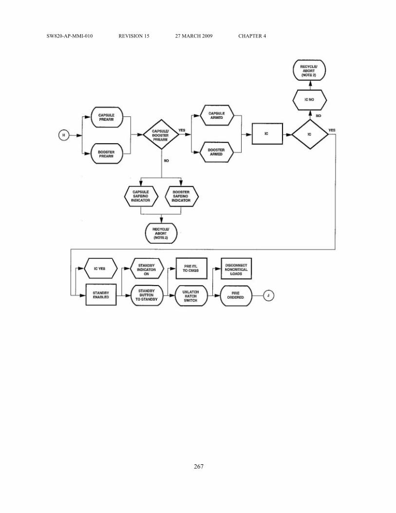
SW820-AP-MMI-010 REVISION 15 27 MARCH 2009 CHAPTER 4
267

SW820-AP-MMI-010 REVISION 15 27 MARCH 2009 CHAPTER 4
268

SW820-AP-MMI-010 REVISION 15 27 MARCH 2009 CHAPTER 4
269

SW820-AP-MMI-010 REVISION 15 27 MARCH 2009 CHAPTER 4
270

SW820-AP-MMI-010 REVISION 15 27 MARCH 2009 CHAPTER 4
Figure 4-21. Lifting Adapter and Extension
271

SW820-AP-MMI-010 REVISION 15 27 MARCH 2009 CHAPTER 4
Figure 4-22. Vertical Launching System Mk 41 Mod 0
272

SW820-AP-MMI-010 REVISION 15 27 MARCH 2009 CHAPTER 4
Figure 4-23. Vertical Launching System Mk 41 Mod 1
273

SW820-AP-MMI-010 REVISION 15 27 MARCH 2009 CHAPTER 4
Figure 4-24. Vertical Launching System Mk 41 Mod 2
274

SW820-AP-MMI-010 REVISION 15 27 MARCH 2009 CHAPTER 4
Figure 4-25. Launch Control Unit (LCU)
275

SW820-AP-MMI-010 REVISION 15 27 MARCH 2009 CHAPTER 4
Figure 4-26. Vertical Launching System Launcher
276

SW820-AP-MMI-010 REVISION 15 27 MARCH 2009 CHAPTER 4
Figure 4-27. Remote Launch Enable Panel (RLEP)
277

SW820-AP-MMI-010 REVISION 15 27 MARCH 2009 CHAPTER 4
Figure 4-28. Status Panel
278

SW820-AP-MMI-010 REVISION 15 27 MARCH 2009 CHAPTER 4
Figure 4-29. Mk 14 VLS Canister PHS&T Equipment
279

SW820-AP-MMI-010 REVISION 15 27 MARCH 2009 CHAPTER 4
Figure 4-30. Secure Canister to Mk 23 Tilt Fixture
280

SW820-AP-MMI-010 REVISION 15 27 MARCH 2009 CHAPTER 4
Figure 4-31. Upright Mk 14 VLS Canister to VerticalPosition
281

SW820-AP-MMI-010 REVISION 15 27 MARCH 2009 CHAPTER 4
Figure 4-32. RGM-109-4 Land-Attack TCMOperational Sequence (15 Sheets)
282

SW820-AP-MMI-010 REVISION 15 27 MARCH 2009 CHAPTER 4
283

SW820-AP-MMI-010 REVISION 15 27 MARCH 2009 CHAPTER 4
284

SW820-AP-MMI-010 REVISION 15 27 MARCH 2009 CHAPTER 4
285

SW820-AP-MMI-010 REVISION 15 27 MARCH 2009 CHAPTER 4
286

SW820-AP-MMI-010 REVISION 15 27 MARCH 2009 CHAPTER 4
287

SW820-AP-MMI-010 REVISION 15 27 MARCH 2009 CHAPTER 4
288

SW820-AP-MMI-010 REVISION 15 27 MARCH 2009 CHAPTER 4
289

SW820-AP-MMI-010 REVISION 15 27 MARCH 2009 CHAPTER 4
290

SW820-AP-MMI-010 REVISION 15 27 MARCH 2009 CHAPTER 4
291

SW820-AP-MMI-010 REVISION 15 27 MARCH 2009 CHAPTER 4
292

SW820-AP-MMI-010 REVISION 15 27 MARCH 2009 CHAPTER 4
293

SW820-AP-MMI-010 REVISION 15 27 MARCH 2009 CHAPTER 4
294

SW820-AP-MMI-010 REVISION 15 27 MARCH 2009 CHAPTER 4
295

SW820-AP-MMI-010 REVISION 15 27 MARCH 2009 CHAPTER 4
296

SW820-AP-MMI-010 REVISION 15 27 MARCH 2009 CHAPTER 4
Figure 4-33. Multiple All-Up-Round Canister (FullyLoaded)
297

SW820-AP-MMI-010 REVISION 15 27 MARCH 2009 CHAPTER 4
Figure 4-34. Tilt Fixture Mk 23 Mod 0 with Kit B
298

SW820-AP-MMI-010 REVISION 15 27 MARCH 2009 CHAPTER 4
Figure 4-35. Multiple All-Up-Round Canister MTELOrientation
299

SW820-AP-MMI-010 REVISION 15 27 MARCH 2009 CHAPTER 4
Figure 4-36. AUR Aft Cover Viewed in MAC
300

SW820-AP-MMI-010 REVISION 15 27 MARCH 2009 CHAPTER 4
Table 4-1. Missile Availability FactorsAVAILABILITY FACTOR OVERRIDEFailure in cell YesNumber of firings from cell exceeds eight (w/oORDALT 16235)
Yes
Number of firing counts from cell is/will be10.75 or greater (w/ ORDALT 16235)
Yes
Missile in cooldown YesMissile fuel leak YesModule hazard/fault YesModule BITE faults YesLaunch-sequence detected fault YesLauncher unauthorized by TWCS NoCanister or plenum cover not present/notdogged down
No
Module declared unavailable NoRestrained missile firing within module NoMCP BITE is on but should not be NoModule set to an offline status NoNo missile in cell NoCell and missile already selected for alaunching
No
Fault previously reported in half modulecontaining the missile
No
Fault previously reported in missile NoLaunch sequence failure previously reported NoLaunch operations not enabled in VLS NoCell-select relay (K1) not energized No
301