shlaer-mellor method: the ooa96 report
TRANSCRIPT

Shlaer-Mellor Method:
The OOA96 ReportVersion 1.0
Sally ShlaerNeil Lang
Project Technology, Inc.2560 Ninth Street, Suite 214
Berkeley, CA 94710510-845-1484
http://www.projtech.com
© Copyright 1996 by Project Technology, Inc. All Rights Reserved. Version 1.0.960109

Copyright 1996 by Project Technology, Inc. 1 OOA96 Report All rights reserved. Version 1.0
Table of Contents
1 Why Revise the Shlaer-Mellor Method?
1.1 Goals 3
1.2 Role of the Report 3
1.3 Dimensions of the Method 3
1.4 Acknowledgments 4
2 Dependence Between Attributes
2.1 Functional Dependence 5
2.2 Stochastic Dependence 7
2.3 Mathematical Dependence 8
3 Relationship Loops
3.1 Loops of Relationships 11
3.2 Characterizing Loops 12
3.3 Depicting Loop Dependency 13
3.4 Summary 17
4 Reflexive Relationships
4.1 Role of Instances in Reflexive Relationships 19
4.2 Modeling Symmetric Reflexive Relationships 19
4.3 Modeling Asymmetric Reflexive Relationships 20
4.4 Summary 22
5 Events
5.1 Event Labels 23
5.2 Data Carried by an Event 23
5.3 Event List 24
5.4 Same Data Rule 24
5.5 Events Within a Domain 24
5.6 Order of Receiving Events 24
5.7 Polymorphic Events 25
6 The FSM Mechanism
6.1 Tables Supplied by the Analyst 29
6.2 Static Event Checking 29
6.3 The Algorithm of the FSM Mechanism 30
6.4 Analysis Errors Detected by the FSM Mechanism 31

Copyright 1996 by Project Technology, Inc. 2 OOA96 Report All rights reserved. Version 1.0
Table of Contents
7 Assigners
7.1 Competitive Relationships 33
7.2 Assigners for Relationships 34
7.3 Assigner Protocol 34
7.4 Multiple Assigners 36
8 Creation and Deletion of Instances
8.1 Time Scope of the Analysis 39
8.2 How Instances Are Created: Axioms and Definitions 39
8.3 How Instances Are Created: Questions and Answers 40
8.4 How Instances Are Deleted: Axioms and Definitions 42
8.5 How Instances Are Deleted: Questions and Answers 43
9 Process Models in OOA96
9.1 Small Changes and Clarifications 45
9.2 Multiple Data Items 46
9.3 Process Types 49
9.4 Delayed Events and Timers 51
9.5 Connecting to Other Domains 52
9.6 Particular Constructs 53

Copyright 1996 by Project Technology, Inc. 3 OOA96 Report All rights reserved. Version 1.0
1
Why Revise the Shlaer-Mellor Method?
Sally ShlaerNeil Lang
Since the last published statement of the Shlaer-Mellor method of Object-Oriented Analysis, acertain number of questions have come forward. These questions range in nature from clarifi-cations required on basic conceptual matters to detailed inquiries involving extremely finepoints of the method. At the same time, as a result of extensive work on client projectsespe-cially those employing the latest generation of Shlaer-Mellor automation toolswe have madesome adjustments and, we believe, improvements to the method.
1.1 Goals
The purpose of this report is to state the rules of OOA as currently defined. We call this state-ment OOA96; it is the statement of OOA that will be relied upon by the upcoming book onRecursive Design. In developing this statement, we have held four primary goals:
■ To define OOA96 so that it is self-consistent.
■ To define OOA96 so that it is as consistent as possible with OOA91 (as defined byObject Lifecycles) while, at the same time, incorporating lessons learned from a broadspread of client projects.
■ To improve the rigor of the method and to tie up various loose ends.
■ To ensure that correct OOA models make clear delineations of domain boundaries.
1.2 Role of the Report
The material given here adds to and supersedes portions of that presented in Object Lifecycles:Modeling the World in States. As a result, we rely upon the reader's familiarity with thedetails provided in that work. We have not attempted to provide here a complete and inte-grated presentation of the method as defined today; such a publication is planned for later inthe year.
1.3 Dimensions of the Method
We distinguish between several dimensions of the method, as follows:
Formalism. First and foremost, OOA96 is a mathematical system, built up of axioms, defini-tions, and theorems. We refer to this mathematical system as a formalism, using the word inmuch the same way as do mathematical physicists. Note that this report is almost entirelyconcerned with the formalism.

OOA96 Report 4 Copyright 1996 by Project Technology, Inc.Version 1.0 All rights reserved.
Representation. Associated with the formalism is a representation, or notation: A definedway to depict the entities of the formalism. The notation that we use has been designed forreadability and for ease of use. We have found it necessary to make only a few minor adjust-ments to the OOA91 notation.
We want to emphasize that we do not attach great significance to the particular notationsemployed in the work products of OOA. Hence if a CASE vendor chooses to adopt some vari-ant representationperhaps for compatibility with other tools or for ease of implementationthis does not, in our opinion, detract from the usefulness of the toolset.
Work products. OOA is laid out in a series of steps, each of which is designed to produce cer-tain work products. The steps and work products of OOA96 are the same as those of OOA91with the following exceptions: (1) The format of the Event List has been slightly modified toaccount for polymorphic events and (2) a small additional work product has been defined toallow explicit integration of domains.
Techniques. Techniques are procedures and processes conducted by software developers inorder to elicit information, develop conceptualizations, etc. Techniques (such as preparationof technical notes, object blitzes, examination of use cases, interviews and the like) are gener-ally not associated directly with the production of a particular work productor even with aparticular method. The scope of this report does not cover techniques: such a publicationremains to be prepared.
1.4 Acknowledgments
Virtually all of Project Technology's instructors, consultants, and architects have contributedtheir capabilities and experiences to the definition of OOA96. In particular, we wish to thankHoward Kradjel, Kent Mingus, Gregory Rochford, Phil Ryals, John Wolfe, and John Yeager forleading numerous spirited debates and thereby forcing us all to clarify our thoughts.

Copyright 1996 by Project Technology, Inc. 5 OOA96 Report All rights reserved. Version 1.0
2
Dependence Between Attributes
Sally ShlaerNeil Lang
There are three kinds of dependencies that may pertain between attributes on the InformationModel (IM). This chapter describes these dependencies and explains how they are repre-sented on the graphic form of the IM.
2.1 Functional Dependence
Functional dependence forms the basis of the relational model of data, upon which OOA'srules of attribution are based. This section extracts a few of the results of the relational model1
to establish some basic principles of OOA.
2.1.1 Structure of an Object
We start out with an axiom:
This axiom ensures that (1) the tabular representation can be used to depict all instances of anobject and (2) that an attribute has no internal structure. As a result, an OOA object is a rela-tion of first normal form in the relational model.
2.1.2 Relationships Between Attributes
Functional dependence has to do with what you have to know in order to determine the valueof an attributethat is, how tightly attributes are related to one another in terms of their mean-ings.
This idea, which is very simple and intuitive for an OOA practitioner, is much more difficultfor a practitioner schooled in the relational model. The difference is this: An OOA practitio-ner starts with the idea of an object as a conceptual entity that can be characterized byattributes; these attributes are tied together in the sense that they characterize the same object.
1. For a more complete presentation, see any standard database text. Especially recommended is C. J. Date's An Introduction to Database Systems, second edition, Addison Wesley, 1977.
AXIOM (Structure of an object): For any OOA object P:
■ Every instance of P can be represented by a tuple.
■ The domain underlying each attribute of P consists of atomic values only.

OOA96 Report 6 Copyright 1996 by Project Technology, Inc.Version 1.0 All rights reserved.
However, the relational modeler starts with relations made up of arbitrary sets of attributes,and is tasked with moving these attributes around between relations until certain “normaliza-tion flaws” have been removed. As a result, the relational modeler must consider issues thatwould never occur to the OOA practitioner (such as the case of multi-valued dependency. Seedatabase textsparticularly Ullman, Principles of Database Systems, Computer Science Press,1982for examples of this “problem;” such examples seem quite paradoxical to the OOAer).
In order to do his work, the relational modeler relies on the following:
So when we say that B is functionally dependent on A, we mean that there is a reason thatguarantees that we can determine the value of attribute B given only the value of attribute A.This reason must be based on the world being modeled (we know that given a dog's name—that is, attribute A—we can determine the dog's weight) and must be of such a nature that itholds for any imaginable instance of the object under consideration.
The definition of functional dependence can be expanded to account for sets of attributes; thisis necessary to account for compound identifiers.
2.1.3 Proper Attribution
By our definition of proper attribution, any OOA object is in fourth normal form.
In OOA, we commonly say that “the attributes of an object are mutually independent.” Whatis meant by this statement is the following:
DEFINITION (Functional dependence on an attribute): Suppose that we have two attributes A and B. Then attribute B is said to be functionally dependent on attribute A if and only if given the value of attribute A (and observational access to instances in the world being modeled), one can determine exactly the value of attribute B.
DEFINITION (Functional dependence on a set): Suppose we have a set of attributes called A and an attribute B. B is not a member of A. Then B is said to be functionally dependent on A if and only if given values for all the attributes in A (and observa-tional access to instances in the world being modeled), one can determine exactly the value of attribute B.
PRELIMINARY DEFINITION (Proper attribution): An OOA object P is said to be properlyattributed if and only if
■ Every attribute of P that is not part of any identifier of P is functionally depen-dent on a complete identifier of the object and not on any proper subset of thatidentifier.
■ If an attribute B of P is functionally dependent on a set A of attributes of P, thenA is an identifier of P.
THEOREM (Mutual functional independence of attributes): Given a properly attributed OOA object and two attributes R and S of that object. Neither R nor S is part of an identifier. Then R is not functionally dependent on S.

Copyright 1996 by Project Technology, Inc. 7 OOA96 Report All rights reserved. Version 1.0
The proof of this theorem is easy to establish: Suppose that R is functionally dependent on S.Then by the definition of proper attribution, S must be an identifier of the object, contrary tothe hypothesis. Therefore, R is not functionally dependent on S.
2.2 Stochastic Dependence
Suppose we have an object
Coin Toss (trial number, time of trial, coin 1, coin 2)
The domain of coin 1 is {H, T}, as is the domain of coin 2. Now we conduct experiments bytaking a pair of coins and tossing them in the air. Then we record the results.
It is clear that this object is in fourth normal form, and that coin 1 and coin 2 are functionallyindependent of one another. But, in addition, coin 1 and coin 2 are said to be stochasticallyindependent of one another: that is, knowing the value of coin 1 gives us no clue to the valueof coin 2. Probabilists talk about this state of affairs as follows:
Pr[ coin 2 = H | coin 1 = H ] = Pr[ coin 2 = H ]
and you read it as “the probability that coin 2 = H (assuming that I already know coin 1 = H) isthe same as the probability coin 2 = H (assuming I know nothing about coin 1).” That is, thevalue of coin 1 has no predictive power as to the value of coin 2.
Now, in the context of a grade school, consider the object:
School child (student ID, grade, height, weight)
The object is properly attributed, and grade, height, and weight are mutually functionallyindependent. However, they are not stochastically independent: I could observe a number ofstudents and make a scatter plot of height vs. grade. Then, if you come in with a new studentand tell me what grade the student is in, I can make a better-than-random guess of the value ofhis height.
Pr [ height > h | grade = g ] ≠ Pr [ height > h ]
One can therefore say that the value of grade has predictive power as to the value of height, orthat height and grade are correlated.
In summary, it is entirely legal for an OOA object to contain attributes that are stochasticallydependent upon other attributes of the same object, so long as the rules involving functionaldependency are observedthat is, so long as the object is properly attributed.
DEFINITION (Stochastic dependence and independence): Two attributes A and B aresaid to be stochastically independent if and only if
Pr[ A=a | B=b ] = Pr[ A=a ]
Two attributes that are not stochastically independent are stochastically dependent.

OOA96 Report 8 Copyright 1996 by Project Technology, Inc.Version 1.0 All rights reserved.
2.3 Mathematical Dependence
Consider the objects
Material ( material ID, density, . . . )
Sample ( sample ID, weight, volume, material ID(R) )
These objects are both in fourth normal form. There is, however, an obvious violation of theconcept of “one fact in one place:” given density and weight, we can determine volume.There are two points to ponder:
■ Any one of these attributes is mathematically dependent on the other two. This doesnot constitute a violation of normalization because the attributes are in different objects.
■ This is a stronger form of dependency than functional dependency: We do not needaccess to instances in the world being modeled in order to determine the value of thethird attribute.
Because attributes of this nature arise fairly commonly in applications, we incorporate thestandard definition of mathematical dependence into OOA:
Now suppose we have an object
Crate ( crate ID, width, height, depth, volume, destination, . . . )
Is Crate in fourth normal form? Because the relational model does not take into account theconcept of mathematical dependence, this question cannot really be answered satisfactorily.However, we can produce structures compatible with the relational model:
Rectangular Solid ( width, depth, height, volume )
Crate ( crate ID, width (R), depth(R), height(R), destination, . . . )
These two objects are properly normalized, but at a cost. You can think through about howyou would want to keep the Rectangular Solid table up to date, and whether or not you wouldwant to keep entries that describe volumes of non-existent crates. But in any case, you wouldhave to search the table every time you added a crate. In summary, creating a RectangularSolid table is not an engineering-style solution.
We resolve this situation as follows:
■ If the model contains a set of attributes that are related through a formula or algorithm,determine a proper subset of these attributes to act as independent variables. Mark theremaining attributes in the setthe dependent variableswith an (M) following theattribute name, as shown in Figure 2.1. This is to be done regardless of whether or notall the attributes in the set are attributes of the same object.
■ In the description of an attribute that represents a dependent variable, cite the formulaor algorithm used to determine the value of the attribute.
DEFINITION: An attribute Y is said to be mathematically dependent on a set of attributes X if and only if, given values of the attributes in X, the value of Y can be determined by a formula or algorithm.

Copyright 1996 by Project Technology, Inc. 9 OOA96 Report All rights reserved. Version 1.0
Figure 2.1: Mark a mathematically dependent attribute with an (M) following the nameof the attribute.
Finally, inclusion of mathematically dependent attributes requires us to refine our definitionof proper attribution.
FINAL DEFINITION (Proper attribution): An OOA object P is said to be properly attrib-uted if and only if
■ Every attribute of P that is not part of any identifier of P is functionally depen-dent on a complete identifier of the object and not on any proper subset of thatidentifier.
■ If an attribute B of P is functionally but not mathematically dependent on a setA of attributes of P, then A is an identifier of P.
1. CRATE
* Crate IDWidthHeightDepthVolume (M)Destination
●
●
●
●
●
2. SAMPLE
* Sample IDWeightVolume (M)Material ID (R6)
●
●
●
3. MATERIAL
* Material IDDensity●
describes
C is describedby
R6

OOA96 Report 10 Copyright 1996 by Project Technology, Inc.Version 1.0 All rights reserved.

Copyright 1996 by Project Technology, Inc. 11 OOA96 Report All rights reserved. Version 1.0
3
Relationship Loops
Neil Lang
During the course of building an Information Model, an analyst may add a relationshipbetween two objects that are already connected by a chain of relationships. In so doing, theanalyst creates a loop of relationships. In this chapter we discuss a set of issues that requireconsideration when forming loops of relationships. In particular we discuss when to formloops, the need to characterize such loops as dependent or independent, and how to repre-sent such loops in the OOA Models.
3.1 Loops of Relationships
When abstracting a relationship that closes a loop of relationships, the analyst first needs toverify that the relationship is required. Does it capture an association not already captured bythe other relationships in the loop? Consider the fragment of an Information Model in Figure3.1 in which relationship
R3: Parent RAISES CHILD WHO ATTENDS School
completes a loop with
R1: Parent RAISES Child and R2: Child ATTENDS School.
But the R3 relationship is nothing more than the concatenation of R1 and R2 and captures nonew associations. R3 is therefore redundant and should not be added to the model.
Figure 3.1: R3 is a redundant loop-closing relationship.
On the other hand, consider the relationship
R4: Parent GRADUATED FROM School
in Figure 3.2. Here R4 captures an association that is clearly different from that captured bythe combination of the R1 and R2 relationships. Therefore R4 is not redundant and it is mostappropriate to add this relationship to the model.
PARENTis raised by
CHILDis attended by
SCHOOLR1 raises attendsR2
is attendedby child raised by
R3
raises childwho attends

OOA96 Report 12 Copyright 1996 by Project Technology, Inc.Version 1.0 All rights reserved.
Figure 3.2: R4 is a non-redundant loop-closing relationship. This is a “loop of independent relationships”.
3.2 Characterizing Loops
Loops of Dependent and Independent Relationships. In some loops instances of the relation-ships in the loop are completely independent. That is, the value of one of more referentialattributes does not constrain the values of the remaining referential attributes. Consider themodel in Figure 3.2. Knowing the children being raised by a parent and the schools theyattend does not tell us anything about the school from which the parent graduated.
On the other hand, there are loops in which instances of the participating relationships areconstrained. Consider the model in Figure 3.3. Here knowing what children a parent is rais-ing and the schools they attend indicates something about the school or schools on whose PTAthe parent serves.
A loop of relationships in which the instances of the relationships are unconstrained is knownas a loop of independent relationships while a loop in which the instances of relationships arerequired to be constrained is known as a loop of dependent relationships. Note that it is theset of relationships composing the loop that we describe as being dependent or independent.We do not categorize individual relationships in a loop as dependent or independent.
Figure 3.3: Example of a “loop of dependent relationships”.
Determining Loop Dependency. Determining the dependency of a loop requires more thanjust a cursory inspection of the objects and relationships. Rather it is the real-world policyunderlying the relationships that governs the loop dependency. A loop with a given set ofobjects and relationships can be either dependent or independent, depending on the underly-ing policy. Consider a university in which Professors work for a single Department, Studentsmajor in one and only one Department, and Students are advised by one and only one Profes-sor. These objects and relationships are captured in the Information Model shown in Figure3.4.
PARENTis raised by
CHILDis attended by
SCHOOLR1 raises attendsR2
graduated
R4
graduatedfrom
PARENTis raised by
CHILDis attended by
SCHOOLR1 raises attendsR2
has PTA with
R5
serves onPTA of

Copyright 1996 by Project Technology, Inc. 13 OOA96 Report All rights reserved. Version 1.0
Figure 3.4: Fragment of an Object Information Model for a university.
Note that the relationships form a loop, but it is impossible to determine the dependency ofthis loop. Whether the instances of relationship R2
Professor ADVISES Student
are required to be constrained by instances of relationship R3
Student MAJORS IN Department
depends on the rules and policies of the university. One university (which we'll identify asUniversity A) allows students to select an advisor from any department regardless of thedepartment in which the student is majoring, while another university (University B) requiresthat students select advisors only from their major department. Understanding the underlyingpolicy that determines whether a loop of relationships is dependent or independent is animportant part of building the Information Model. The analyst must build models that cor-rectly reflect all real-world policies in order to ensure that any design or code derived fromthese models permit only those associations allowed by these policies.
3.3 Depicting Loop Dependency
Loops of Independent Relationships. Once the analyst has determined the dependency of aloop, that dependency needs to be expressed in the model itself. To show that a loop is inde-pendent, formalize each relationship in the loop separately. Note that this produces a modelin which the instances of the participating relationships can be populated in a completelyunconstrained manner. Because the policies at University A require the loop to be modeled asa loop of independent relationships, we need to formalize each relationship separately tocomplete the model for University A (see Figure 3.5).
1. DEPARTMENT (D)
R2
provides specialization for
R1
staffed by
on staff of
advised by
advises
* Department ID
3. STUDENT (S)
* Student ID
2. PROFESSOR (P)
* Professor ID
majors in
R3
●
●
●

OOA96 Report 14 Copyright 1996 by Project Technology, Inc.Version 1.0 All rights reserved.
Figure 3.5: Relationships formalized to indicate a loop of independent relationships.
Loops of Dependent Relationships. To model a loop of dependent relationships, first formal-ize all relationships as usual. Then tag a referential attribute in the object with the mostinstances with a “c” to show that its allowable values are constrained by the actual value ofother referential attributes formalizing the loop. Since the object with the most instances willalmost always have a pair of referential attributes, we can choose to tag either of them. (SeeFigure 3.6 for two ways to build the loop of dependent relationships for University B.) Ineither case, we will also need to document the actual constraint in the object and attributedescriptions. Note that this tagging is simply a reminder to the analyst who will still have toincorporate the constraint formally somewhere in the complete OOA model. In this example,the analyst will most likely add extra processing to the state model for the Student object tocheck that the advisor belongs to the Department in which the Student is majoring.
Figure 3.6: Two ways to formalize a loop of dependent relationships using constrained referential attributes.
1. DEPARTMENT (D)
R2
provides specialization for
R1
staffed by
on staff of
advised by
advises
* Department ID
3. STUDENT (S)
* Student ID
Professor ID (R2)Department ID (R3)
2. PROFESSOR (P)
* Professor ID
Department ID (R1)
majors in
R3
●
●
●
●
●
●
1. DEPARTMENT (D)
R2
provides specialization for
R1
staffed by
on staff of
advised by
advises
* Department ID
3. STUDENT (S)
* Student IDProfessor ID (R2c)Department ID (R3)
2. PROFESSOR (P)
* Professor IDDepartment ID (R1)
majors in
R3
●
●
●
constrained domain: can only be a professor from student's major department
1. DEPARTMENT (D)
R2
provides specialization for
R1
staffed by
on staff of
advised by
advises
* Department ID
3. STUDENT (S)
* Student IDProfessor ID (R2)Department ID (R3c)
2. PROFESSOR (P)
* Professor IDDepartment ID (R1)
majors in
R3
●
●
●
constrained domain: must be same as department of advisng professor

Copyright 1996 by Project Technology, Inc. 15 OOA96 Report All rights reserved. Version 1.0
In certain cases we may be able to modify the models developed above so that the loop depen-dency is expressed directly in data. This would then guarantee that regardless of how themodel was populated the instances of the relationships would always be constrained as neces-sary. The two following sections present two situations in which such modification is possi-ble.
Collapsed Referentials. Consider what occurs if we replace the arbitrary identifiers for theProfessor and Student objects with compound identifiers involving a Department ID (see Fig-ure 3.7). When we formalize R2 and R3, we add two sets of referential attributes incorporatingDepartment ID to the Student object (Major Department ID(R3) and Advisor DepartmentID(R2)).
Figure 3.7: Formalizing a loop of dependent relationships using compound identifiers with constraints.
The loop constraint is now very easy to capture as Major Department ID(R3) must always equalAdvisor Department ID(R2). We show this (see Figure 3.8) with Department ID(R2,R3), that is,a single referential attribute formalizing two relationships simultaneously. The use of col-lapsed referentials in loops often allows us to represent the loop dependency directly in data.Doing so guarantees that whenever we populate the model the constraints are automaticallysatisfied.
Figure 3.8: Formalizing a loop of dependent relationships using collapsed referentials.
1. DEPARTMENT (D)
R2
provides specialization for
R1
staffed by
on staff of
advised by
advises
* Department ID
3. STUDENT (S)
* Major department ID (R3C)Student number indepartmentAdvisor Department ID (R2)Professor number indepartment (R2)
2. PROFESSOR (P)
* Department ID (R1)Professor numberin department
majors in
R3
●
●
*
*
1. DEPARTMENT (D)
R2
provides specialization for
R1
staffed by
on staff of
advised by
advises
* Department ID
3. STUDENT (S)
* Department ID (R2, R3)Student number indepartmentProfessor numberin department (R2)
2. PROFESSOR (P)
* Department ID (R1)Professor numberin department
majors in
R3
●
*
*
OOA96 Report 16 Copyright 1996 by Project Technology, Inc.Version 1.0 All rights reserved.
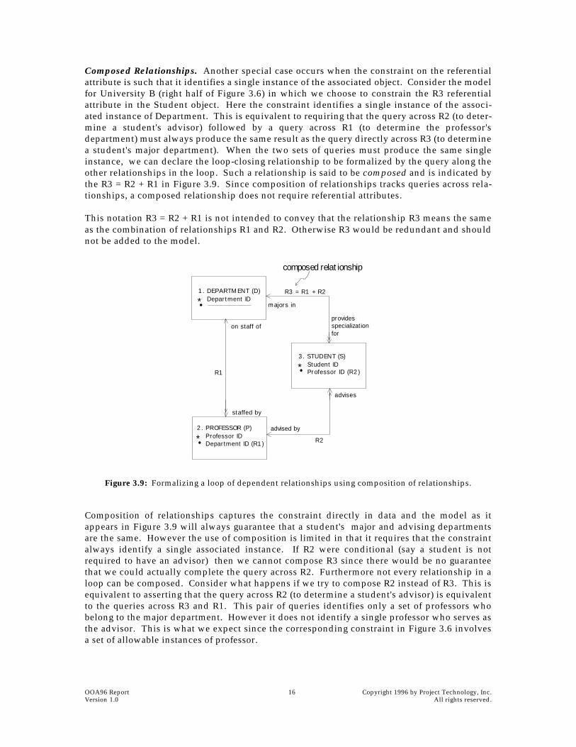
Composed Relationships. Another special case occurs when the constraint on the referentialattribute is such that it identifies a single instance of the associated object. Consider the modelfor University B (right half of Figure 3.6) in which we choose to constrain the R3 referentialattribute in the Student object. Here the constraint identifies a single instance of the associ-ated instance of Department. This is equivalent to requiring that the query across R2 (to deter-mine a student's advisor) followed by a query across R1 (to determine the professor'sdepartment) must always produce the same result as the query directly across R3 (to determinea student's major department). When the two sets of queries must produce the same singleinstance, we can declare the loop-closing relationship to be formalized by the query along theother relationships in the loop. Such a relationship is said to be composed and is indicated bythe R3 = R2 + R1 in Figure 3.9. Since composition of relationships tracks queries across rela-tionships, a composed relationship does not require referential attributes.
This notation R3 = R2 + R1 is not intended to convey that the relationship R3 means the sameas the combination of relationships R1 and R2. Otherwise R3 would be redundant and shouldnot be added to the model.
Figure 3.9: Formalizing a loop of dependent relationships using composition of relationships.
Composition of relationships captures the constraint directly in data and the model as itappears in Figure 3.9 will always guarantee that a student's major and advising departmentsare the same. However the use of composition is limited in that it requires that the constraintalways identify a single associated instance. If R2 were conditional (say a student is notrequired to have an advisor) then we cannot compose R3 since there would be no guaranteethat we could actually complete the query across R2. Furthermore not every relationship in aloop can be composed. Consider what happens if we try to compose R2 instead of R3. This isequivalent to asserting that the query across R2 (to determine a student's advisor) is equivalentto the queries across R3 and R1. This pair of queries identifies only a set of professors whobelong to the major department. However it does not identify a single professor who serves asthe advisor. This is what we expect since the corresponding constraint in Figure 3.6 involvesa set of allowable instances of professor.
1. DEPARTMENT (D)
R2
provides specialization for
R1
staffed by
on staff of
advised by
advises
* Department ID
3. STUDENT (S)
* Student IDProfessor ID (R2)
2. PROFESSOR (P)
* Professor IDDepartment ID (R1)
majors in
R3 = R1 + R2
●
●
●
composed relationship

Copyright 1996 by Project Technology, Inc. 17 OOA96 Report All rights reserved. Version 1.0
3.4 Summary
Adding a relationship that closes a loop in an Information Model requires that the analyst firstverify that the relationship is not a redundant relationship. Then he or she must understandthe underlying real-world policy in order to determine whether the loop is a loop of depen-dent or independent relationships. If the loop is an independent loop, formalize each rela-tionship in the loop separately. If the loop is a dependent loop, use either constrainedreferential attributes, collapsed referentials, or composition of relationships as appropriate tocapture the loop constraints. This effort ensures that the model reflects all real-world con-straints correctly. Furthermore any design and code produced by translating the analysismodel will then automatically incorporate such constraints.

OOA96 Report 18 Copyright 1996 by Project Technology, Inc.Version 1.0 All rights reserved.

Copyright 1996 by Project Technology, Inc. 19 OOA96 Report All rights reserved. Version 1.0
4
Reflexive Relationships
Neil Lang
In the Shlaer-Mellor method, relationships are abstractions of associations that hold systemat-ically between instances of objects. Analysts usually recognize associations between instancesof different objects and abstract the corresponding relationships. Occasionally an analystmodels a relationship that abstracts systematic associations between instances of the sameobject. In OOA96 we refer to such relationships as reflexive and in this chapter we will dis-cuss a variety of ways to model reflexive relationships.
4.1 Role of Instances in Reflexive Relationships
Consider the following reflexive relationship:
Employee WORKS WITH Employee (Mc:Mc)
The order of the associated instances is not significant. ‘Fred works with Ginger’ conveys thesame fact as ‘Ginger works with Fred’. The instances play identical roles, and the multiplicityand conditionality of the relationship must be the same from the perspective of each of theparticipating instances. We refer to such reflexive relationships as non-directional or role-symmetric.
Now consider the following reflexive relationship:
Employee SUPERVISES Employee (1:Mc)
In this case, the order of the instances is significant: ‘Lou supervises Mary’ is very differentfrom ‘Mary supervises Lou’. Each instance in a relationship assumes a specific role. Oneinstance of Employee is a supervising employee while the other is an employee being super-vised. Furthermore the multiplicity and conditionality of such relationships can be differentat each end. An employee being supervised must have exactly one supervisor while a super-vising employee may supervise one or more employees. Such a relationship has a very direc-tional character; we term it asymmetric.
4.2 Modeling Symmetric Reflexive Relationships
On the Information Model, show a symmetric relationship with a relationship line that loopsback to the object. Since, by definition, such a relationship must have the same name, multi-plicity, and conditionality at each end, name and characterize the relationship at one endonly. To ensure that an instance of the relationship appears only once in the model, alwaysformalize the relationship with an associative object regardless of the multiplicity of the rela-tionship itself. In Figure 4.1 we show the Employee WORKS WITH Employee relationship so for-malized.
OOA96 Report 20 Copyright 1996 by Project Technology, Inc.Version 1.0 All rights reserved.
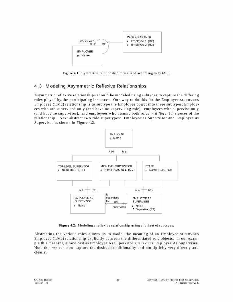
Figure 4.1: Symmetric relationship formalized according to OOA96.
4.3 Modeling Asymmetric Reflexive Relationships
Asymmetric reflexive relationships should be modeled using subtypes to capture the differingroles played by the participating instances. One way to do this for the Employee SUPERVISES
Employee (1:Mc) relationship is to subtype the Employee object into three subtypes: Employ-ees who are supervised only (and have no supervising role), employees who supervise only(and have no supervisor), and employees who assume both roles in different instances of therelationship. Next abstract two role supertypes: Employee as Supervisor and Employee asSupervisee as shown in Figure 4.2.
Figure 4.2: Modeling a reflexive relationship using a full set of subtypes.
Abstracting the various roles allows us to model the meaning of an Employee SUPERVISES
Employee (1:Mc) relationship explicitly between the differentiated role objects. In our exam-ple this meaning is now cast as Employee As Supervisor SUPERVISES Employee As Supervisee.Note that we can now capture the desired conditionality and multiplicity very directly andclearly.
EMPLOYEE
* Name
works withR2
WORK PARTNER
**
Employee 1 (R2)Employee 2 (R2)C
EMPLOYEE
* Name
TOP-LEVEL SUPERVISOR
* Name (R10, R11)MID-LEVEL SUPERVISOR
* Name (R10, R11, R12)STAFF
* Name (R10, R12)
R10 is a
EMPLOYEE ASSUPERVISOR
* Name
R11
EMPLOYEE ASSUPERVISEE
* NameSupervisor (R3)
R12
●
is supervisedby
supervises
R3
is a is a

Copyright 1996 by Project Technology, Inc. 21 OOA96 Report All rights reserved. Version 1.0
We need to use this form whenever the three subtypes have different characteristics. Mid-Level and Top-Level Supervisors may have additional attributes as a result of their respectiveresponsibilities. In cases where two or more of the subtypes have no distinguishing attributes,we can use a partially collapsed form of the model as shown in Figure 4.3. Here we replacedTop-Level Supervisor and Mid-Level Supervisor with Supervisor. We now have one subtypeto represent those employees who are only supervised (Staff) and one subtype for thoseemployees that do some supervising (Supervisor). When we do this, we model the SUPERVISES
relationship between one of the subtypes and the supertype. Note that we also had to makethe relationship conditional since not all instances of Employee (the supertype) are necessarilysupervised.
Figure 4.3: Modeling a reflexive relationship using a partial set of subtypes.
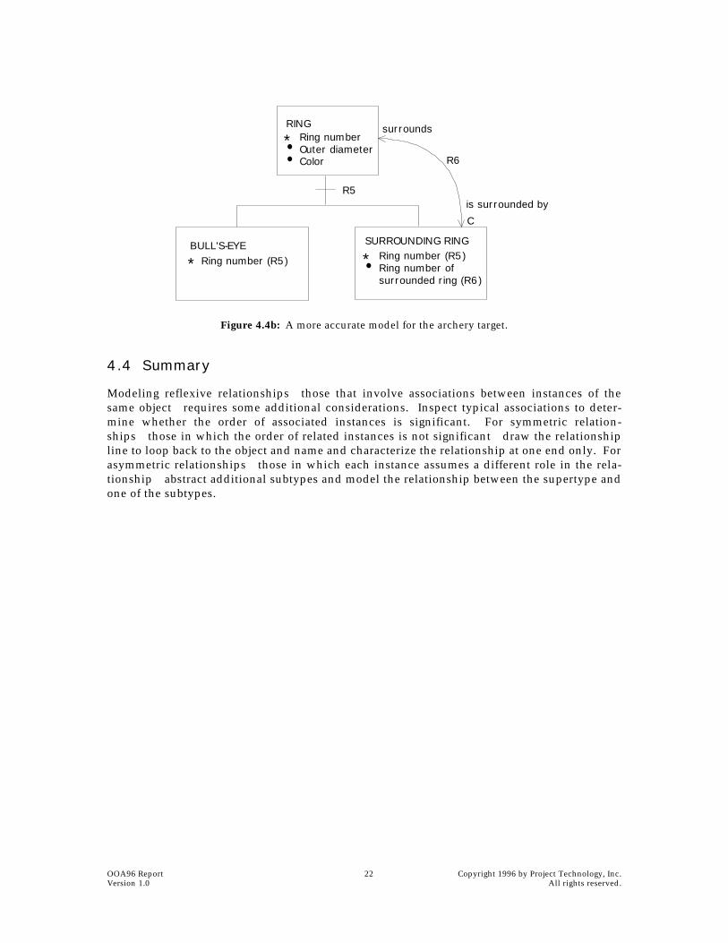
Let us consider one more example. Suppose that we wish to capture the design of an archerytarget as a series of concentric nested rings. Figure 4.4a represents our first attempt to modelthis situation. This model succeeds in capturing the dimensions of the outer rings (the innerdiameter of a ring is the same as the outer diameter of the ring it surrounds), but it fails to treatthe central “ring”—the bullseye—correctly: (1) the central ring doesn’t surround any ring and(2) the inner diameter of the central ring is zero. Since this relationship has an asymmetricnature (Ring 3 SURROUNDS Ring 2 means something very different from Ring 2 SURROUNDS Ring3) we now model it using subtypes. In Figure 4.4b we recast the model using two subtypes:Innermost Ring and Surrounding Ring. Note how this version of the model allows us to cap-ture the fact that the innermost ring does not surround another ring, something that wasimpossible with the form in Figure 4.4a. In addition, by separating out the innermost ring, wehave made it possible to apply a different policy to it. Should we want to calculate the area ofeach ring, we can use one formula for the bullseye and a different formula for the outer rings.
Figure 4.4a: A weak model of the rings of an archery target.
EMPLOYEE
* NameSupervisor (R3)
SUPERVISOR
* Name (R10)STAFF
* Name (R10)
R10
C
issupervised
by
R3
supervises
●
RING
* Ring numberOuter diameterColorRing number ofsurrounded ring (R6)
CR6is surrounded by
surrounds●
●
●
C
OOA96 Report 22 Copyright 1996 by Project Technology, Inc.Version 1.0 All rights reserved.
Figure 4.4b: A more accurate model for the archery target.
4.4 Summary
Modeling reflexive relationshipsthose that involve associations between instances of thesame objectrequires some additional considerations. Inspect typical associations to deter-mine whether the order of associated instances is significant. For symmetric relation-shipsthose in which the order of related instances is not significantdraw the relationshipline to loop back to the object and name and characterize the relationship at one end only. Forasymmetric relationshipsthose in which each instance assumes a different role in the rela-tionshipabstract additional subtypes and model the relationship between the supertype andone of the subtypes.
RING
* Ring numberOuter diameterColor
BULL'S-EYERing number (R5)
R5
C
●
● R6
*
SURROUNDING RINGRing number (R5)Ring number ofsurrounded ring (R6)
*●
surrounds
is surrounded by

Copyright 1996 by Project Technology, Inc. 23 OOA96 Report All rights reserved. Version 1.0
5
Events
Sally ShlaerNeil Lang
The concept of an event remains the same as in OOA91. However, some rules have beenstrengthened to eliminate certain rare ambiguous cases. In addition, the formalism has beenextended to include the concept of polymorphic events.
5.1 Event Labels
Object Lifecycles (p. 42) suggests two different conventions for assigning event labels. Becauseone of these conventionsdestination-based labelinghas been virtually universally adoptedby the user community, we now promote the convention to a rule:
5.2 Data Carried by an Event
In OOA91, an event could carry supplemental data as well as an identifier of the instance towhich it was directed. These two types of event data remain in OOA96; the only difference isthat we now make a precise distinction between them on the models.
The syntax for an OOA96 event is
E1: event meaning ( identifying attribute(s); supplemental data item(s) )
where either the identifier or the supplemental data items (or both) may be missing. Hence anevent directed to an existing instance has one of the forms
E2: event meaning ( identifying attribute(s); )
E3: event meaning ( identifying attribute(s); supplemental data item(s) )
while an event directed to a single-instance assigner1 may have either of the forms
E4: event meaning ( ; supplemental data item(s) )
1. The assigners that were defined in OOA91 are now known as single-instance assigners. OOA96 also allows for multi-instance assigners. See Chapter 7.
RULE (event labeled by destination): If a non-polymorphic event is directed toan object, the label of that event must begin with the key letter of that object.

OOA96 Report 24 Copyright 1996 by Project Technology, Inc.Version 1.0 All rights reserved.
E5: event meaning ( ; )
Finally, because a creation event is not directed at an existing instance, it has the form
E6: create instance ( ; supplemental data item(s) ).
In this case, it is likelybut not requiredthat values for the identifying attributes for theinstance to be created will be carried in the supplemental data items.
5.3 Event List
Now that we distinguish between identifying attributes and supplemental data carried by anevent, the format of the Event List becomes:
The Destination column has been removed from the event list because, as a result of the eventlabeling rule of Section 5.1, it is now redundant with the Event Label column.
5.4 Same Data Rule
Now that the form of an event has been defined more precisely, the “same data” rule (ObjectLifecycles, page 43) is modified as follows:
5.5 Events Within a Domain
Events generated in an action in a domain must be received by an instance in the samedomain. It is no longer permitted to generate an event that is intended for an object in anotherdomain.
For information about communication between instances in different domains, see Chapter 9.
5.6 Order of Receiving Events
In OOA91, the only rule regulating the order in which events are received applied to eventstransmitted between a single sender/receiver pair. In all other cases OOA91 made no assump-tions, and the analyst was directed to ensure that the state models operated properly regardlessof the order in which events were received.
Label Meaning Identifying attributes
Supplemental data Source(s)
V1 Button pushed oven ID (none) buttonL1 Turn on light light ID (none) oven
A5 create account (none)customer ID,deposit amount
external
. . . . . . . . . . . . . . .
RULE (same data for a transition): All events that cause a transition into a particular state must carry exactly the same event data identifying attributes and the same sup-plemental data items.

Copyright 1996 by Project Technology, Inc. 25 OOA96 Report All rights reserved. Version 1.0
However, in some cases this policy required the analyst to provide additional logic that had noreal value in the domain under consideration. To remedy this problem, OOA96 imposes anadditional rule:
5.7 Polymorphic Events
5.7.1 Concepts
Figure 5.1 shows a fragment of an Information Model in schematic form. Let us suppose thatwe have defined lifecycle state models for objects T, U and V. Object S, the supertype of T, Uand V, has no lifecycle model.
Figure 5.1: C would like to generate an event to an instance of a subtype of S. C has the identifier of the instance, but does not know what subtype the instance belongs to.
Now suppose that an instance of object C would like to generate an event to an instance of S(and therefore to an instance of one of the subtypes of S). C knows the identifier of theintended recipient, but doesn't know what subtype the intended recipient belongs to.
This situation is analogous to the notion of polymorphism in OOP, in which one would like toinvoke a particular method of a child class. Each child class has its own version of themethod, and all the caller knows is the name of the method and the fact that the instance ofinterest belongs to a child class of a known parent class. In such a case, an OO languageallows one to invoke the method as if it were a method of the parent class. The semantics ofthe programming languageand therefore its inherent mechanismsensure that a method ofthe same name in the appropriate child class is actually invoked. Such an invocation isknown as a polymorphic invocation.
In OOA96, we allow for the concept of “polymorphic events.” Returning to our example, weallow C to generate an event that appears to be directed at the supertype S, but which will, infact, be received by an instance of one of the subtypes T, U or V.
5.7.2 Defining Polymorphic Events
Naming a polymorphic event. A polymorphic event has multiple event labels. The labelused by the sender employs the key letter of the supertype that is the apparent recipient. The
RULE (expedite self-directed events): If an instance of an object sends an event to itself, that event will be accepted before any other events that have yet to be accepted by the same instance.
S C
T U V

OOA96 Report 26 Copyright 1996 by Project Technology, Inc.Version 1.0 All rights reserved.
labels used by the true recipients employ their own key letters. Hence in the example of Fig-ure 5.1, the sender (object C) labels the event with an S, while the true recipients know thisevent by, say, T3, U1, and V6.
Polymorphic event table. To define the relationship between the polymorphic event and theactual events as known to the true recipients, the analyst must prepare a polymorphic eventtable as shown below. This table, like the event list, applies to the entire domain.
It is the analyst's responsibility to supply true event labels so that a polymorphic event can bereceived by every instance of the supertype, regardless of which subtype the instance alsoinhabits.
Because the polymorphic event label is only an alias for the true event labels, the followingrule applies to all polymorphic events.
State models. To specify the generation of a polymorphic event, an action description in thestate model of C must contain
generate S1*: event name ( S ident; )
The purpose of the asterisk is simply to remind the reader of the model that the event is poly-morphic, and that the true recipient of such an event is not the object implied by the eventlabel.
Object Communication Model. Like any other event, a polymorphic event is shown on theObject Communication Model (Figure 5.2) as a labeled arrow from the sender of the event tothe true (and not the apparent) receiver. Note that the arrows are annotated with the eventlabels known by both the sender and the various true receivers. Object S does not appear onthe OCM because, in this example, we are assuming that S doesn't have a state model.
Figure 5.2: Object Communication Model showing the polymorphic event S1 and the related true events T3, U1, and V6.
Polymorphic (sender's) label
True (recipient's) label
S1 T3S1 U1S1 V6. . . . . .
RULE (same data for polymorphic aliases): If two or more true events are aliased to the same polymorphic event, the true events must carry values for exactly the same identifying attributes and the same supplemental data items.
C
T U V
T3=S1
U1=S1 V6=S1

Copyright 1996 by Project Technology, Inc. 27 OOA96 Report All rights reserved. Version 1.0
This leads to a very important point: the state model (if anysee further discussion below) ofthe supertype object plays no role in the routing of a polymorphic event. This chore is specif-ically defined as a mechanism within the formalism of OOA.
5.7.3 Can an Instance Have More Than One State Model?
Figure 5.3 depicts a structure in which a single instance of an object (in this case, an instanceof S) has two separate and different state models. Should this be legal in OOA? We have twoanswers: one based on experience, and one based on theory.
Figure 5.3: Can an instance have more than one state model?
The experience-based answer says no. In the models we have seen showing this kind of con-struction, we have found other seemingly unrelated analysis errors. When the models werereconstructed to eliminate these errors, the need for multiple state models disappeared. Henceexperience indicates that multiple state models for a single instance is unlikely to make sense.
On the other hand, theoretical arguments have not yet provided us with a definitive answeryea or nay. In particular, we haven't been able to prove that a multiple state model construc-tion would necessarily lead to an inconsistency in the model. However, we have also not beenable to come up with a reasonable interpretation of such a construction: What could it meanfor an instance to have multiple lifecycles? So, while theory does not provide us with a con-clusive answer, it tends to indicate that the answer should be “yes”.
Hence, faced with this division of evidence, for OOA96 we continue to advise:
1. Avoid, if you can, constructing a model in which a single instance has multiple statemodels.
2. If an instance must have multiple state models, make sure that the state models areindependent of one another—that is, that an action in one state model does not need toknow what state the instance occupies in its other state model in order to operate cor-rectly.
S
A B
X Y
state model here
state model here
state model here
state model here

OOA96 Report 28 Copyright 1996 by Project Technology, Inc.Version 1.0 All rights reserved.
Copyright 1996 by Project Technology, Inc. 29 OOA96 Report All rights reserved. Version 1.0
6
The FSM Mechanism
Sally Shlaer
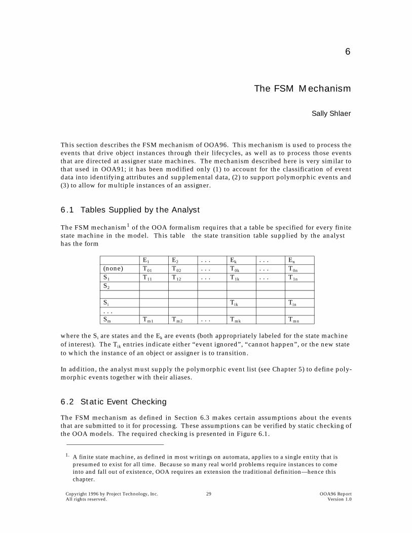
This section describes the FSM mechanism of OOA96. This mechanism is used to process theevents that drive object instances through their lifecycles, as well as to process those eventsthat are directed at assigner state machines. The mechanism described here is very similar tothat used in OOA91; it has been modified only (1) to account for the classification of eventdata into identifying attributes and supplemental data, (2) to support polymorphic events and(3) to allow for multiple instances of an assigner.
6.1 Tables Supplied by the Analyst
The FSM mechanism1 of the OOA formalism requires that a table be specified for every finitestate machine in the model. This tablethe state transition table supplied by the analysthas the form
where the Si are states and the Ek are events (both appropriately labeled for the state machine of interest). The Tik entries indicate either “event ignored”, “cannot happen”, or the new state to which the instance of an object or assigner is to transition.
In addition, the analyst must supply the polymorphic event list (see Chapter 5) to define poly-morphic events together with their aliases.
6.2 Static Event Checking
The FSM mechanism as defined in Section 6.3 makes certain assumptions about the eventsthat are submitted to it for processing. These assumptions can be verified by static checking ofthe OOA models. The required checking is presented in Figure 6.1.
1. A finite state machine, as defined in most writings on automata, applies to a single entity that is presumed to exist for all time. Because so many real world problems require instances to come into and fall out of existence, OOA requires an extension the traditional definition—hence this chapter.
E1 E2 . . . Ek . . . En
(none) T01 T02 . . . T0k . . . T0n
S1 T11 T12 . . . T1k . . . T1n
S2
Si Tik Tin
. . .Sm Tm1 Tm2 . . . Tmk Tmn

OOA96 Report 30 Copyright 1996 by Project Technology, Inc.Version 1.0 All rights reserved.
Key letter corresponds to . . .?
Active object or multiple instance assigner:Does event appear in STT?
yes:Is there a 'can't happen' entry for this event in the 'none' row?
yes: (event is a non-creation event)Does the event carry identifying attributes?
yes:OKno: ERROR (a non-creation event must have identifying attributes)
no:Is there a 'event ignored' entry for this event in the 'none' row?
yes: ERROR (only valid entries in 'none' row are 'can't happen' or 'new state')no:
Is there a 'new state' entry for this event in the 'none' row only?yes: (event must be a creation event)
Does the event carry identifying attributes?yes:ERROR (creation event incorrectly formed)no: OK
no: ERROR (a non-creation event is also a creation event)no: ERROR (undefined event)
Passive object: (checking a possibly polymorphic event)Is object a supertype?
yes:Are there complete entries for this event in the polymorphic event table?
yes:Does the event carry identifying attributes?
yes:OKno: ERROR. (polymorphic event cannot be a creation event)
no: ERROR (aliases not completely defined)no: ERROR (polymorphic event must carry identifier of supertype)
Single-instance assigner:Does event appear in STT?
yes:Is there a 'can't happen' entry for this event in the 'none' row?
yes: (event is a non-creation event)Does the event carry identifying attributes?
yes:ERROR (events to single-instance assigners cannot have identifying attributes)no: OK
no: ERROR (creation events to single-instance assigners are not allowed)no: ERROR (undefined event)
Otherwise: ERROR (event to non-existent object)
Figure 6.1: Static checking for events. This check is done at analysis time to verify that all events in the models can be processed by the FSM mechanism.
6.3 The Algorithm of the FSM Mechanism
Each event is submitted to the FSM mechanism, which determines to which object or assignerthe event is directed and then to which instance of that object or assigner. As a result of thestatic checking performed earlier, we know that:
■ Any event submitted to the FSM mechanism bears the key letter of an object or assigner.
■ Any polymorphic event can be delivered (provided that the targeted instance exists).
■ Any event directed to a single-instance assigner carries no identifying attributes.
The algorithm of the FSM mechanism is given in Figure 6.2. Note that in OOA96, it is theresponsibility of the FSM mechanism to maintain the current state of all instances in the modelthat have state machines. This is consistent with the policy (see Chapter 9) that makes “currentstate” part of the formalism itself so that the analyst no longer has the need (or capability) to setthe current state of an instance directly.

Copyright 1996 by Project Technology, Inc. 31 OOA96 Report All rights reserved. Version 1.0
Is the event polymorphic?yes:
Find instance in supertype object corresponding to polymorphic event label. Find same instance in some subtype. Find true event label corresponding to the identified subtype in the polymorphic event table. Using this event as the submitted event, go to 'Key letter corresponds to'
no:go to 'Key letter corresponds to'
Key letter corresponds to:active object or multiple-instance assigner:
Does the event carrying identifying attributes?yes: (non-creation event)
Does the instance exist?yes:
Find entry in STT corresponding to this event and the instance's current state.Is entry . . .?
event ignored: DONEcan't happen: ERRORnew state: Set current state to new state and invoke action of new state.
no: ERRORno: (creation event)
Find entry corresponding to the event in "none" row of the STT.Is entry . . .?
can't happen: ERRORnew state: Invoke action of new state.
single-instance assigner:Find entry in STT corresponding to this event and the current state.Is entry . . .?
event ignored: DONEcan't happen: ERRORnew state: Set current state to new state and invoke action of new state.
Figure 6.2: How events are processed by the FSM mechanism.
6.4 Analysis Errors Detected by the FSM Mechanism
As shown in Figure 6.2, there are two errors that can only be detected by the FSM mechanism.
■ Can't happen: If an event is received in a given state and the analyst has declared thatsuch an event cannot occur when the instance is in that state, then the analysis is defec-tive and must be repaired.
■ Instance does not exist: The FSM mechanism has received an event directed at aninstance that does not exist. This generally indicates an hole in the application protocolsuch that events have been received in an order not intended by the analyst: either thetargeted instance has not yet been created, or it has already been deleted.
■ It is the responsibility of the analyst to develop an application protocol such that eventscan be received only in an order that makes sense. In this case, a solution may be devel-oped by routing all events to a common recipient through a common sender.

OOA96 Report 32 Copyright 1996 by Project Technology, Inc.Version 1.0 All rights reserved.

Copyright 1996 by Project Technology, Inc. 33 OOA96 Report All rights reserved. Version 1.0
7
Assigners
Neil Lang
Assigners were introduced in OOA91 to manage the creation of relationships in which there iscompetition for instances. In OOA96 we have made the following changes and extensions toassigners:
■ Assigners are associated with relationships instead of associative objects
■ Assignment protocols have been modified to reflect the fact that current state is now maintained internally by the architecture.
■ The concept of an assigner has been extended to allow for multiple assigners to permit concurrent management of assignments where appropriate.
7.1 Competitive Relationships
Instances of relationships are often formed and deleted during the lifecycles of interactingobjects. In many cases the selection of the pair of instances to be related can appear in thestate model of one of the participating objects. However this will not work in all situations;consider the Clerk SERVES Customer relationship in Figure 7.1. If we place the selection ofclerks in the Customer state model, multiple instances of one object (Customer) could allsimultaneously select the same instance of the other object (Clerk). We refer to this as compe-tition for instances, and in OOA96 we refer to relationships such as R3 as competitive rela-tionships.
Figure 7.1: Information model for Customer-Clerk problem.
Objects participating in a competitive relationship must have both state(s) in which instancesare available for assignment as well as state(s) in which the relationship exists. Competitiverelationships must therefore be conditional at both ends. This was implied but not madeexplicit in OOA91.
CLERK (CL)Clerk ID*●
●
CUSTOMER (CU)Customer ID*●
●
R3
isservedby
serves
SERVICE (S)
Clerk ID (R3)Customer ID (R3)
*●
C
C

OOA96 Report 34 Copyright 1996 by Project Technology, Inc.Version 1.0 All rights reserved.
7.2 Assigners for Relationships
The key to managing competitive relationships is the use of a single point of control to assigninstances of the participating objects to each other. In OOA91 we introduced the assigner asthis single point of control. The assigner, in OOA91, was a special state model associated withthe associative object formalizing a competitive relationship. The assigner state model hadone purpose only and that was to create instances of the associative object. The assigner statemodel had nothing to do with the behavior of the associative object. A separate lifecycle statemodel would be developed whenever there was interesting behavior.
An assigner fundamentally creates instances of a competitive relationship. In OOA96, weassociate the assigner directly with the competitive relationship. Assigners bear the name ofthe relationship, and event identifiers for events directed to an assigner are based on the rela-tionship number.
Associating assigners with relationships has two very desirable consequences. First, the ana-lyst is now free to choose how to formalize the competitive relationship and is no longerforced to do so with an associative object. Secondly, all objects have, at most, one possiblestate model: a lifecycle model.
7.3 Assigner Protocol
In OOA91 the checking and selection performed by an assigner was based on the current stateattribute. In OOA96 the current state attribute is maintained by the architecture and will beinaccessible to the application domain models. Therefore we now must add an attribute toeach of the objects involved in a competitive relationship to maintain status with respect to itsassignment (we refer to this attribute as availability status). The analyst defines appropriatevalues for these attributes and specifies processing in the state models in the domain beingmodeled to manage these attributes. Figure 7.2 shows the example involving Clerks and Cus-tomers with availability status attributes added to both the Clerk and the Customer objects.Also note that we have chosen to formalize the competitive relationship R3 by copying theidentifier of the Customer object into the Clerk object rather than using the previously requiredassociative object.
Figure 7.2: Revised information model for Customer-Clerk problem.
A slightly modified assigner protocol is used:
■ Instances ready for assignment first set their availability status attribute to indicate that they are available.
■ They then generate an event to notify the assigner they are available.
CLERK (CL)Clerk ID
Customer ID (R3)Availability status
*●●
●
CUSTOMER (CU)Customer ID
Availability status
*●●
●
isservedby
servesC
C
Values: available assigned
Values: available assigned
R3
Copyright 1996 by Project Technology, Inc. 35 OOA96 Report All rights reserved. Version 1.0
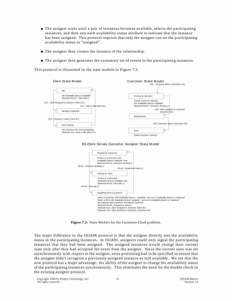
■ The assigner waits until a pair of instances becomes available, selects the participating instances, and then sets each availability status attribute to indicate that the instance has been assigned. This protocol requires that only the assigner can set the participating availability status to “assigned”.
■ The assigner then creates the instance of the relationship.
■ The assigner then generates the customary set of events to the participating instances.
This protocol is illustrated in the state models in Figure 7.3.
Figure 7.3: State Models for the Customer-Clerk problem.
The major difference in the OOA96 protocol is that the assigner directly sets the availabilitystatus in the participating instances. In OOA91, assigners could only signal the participatinginstances that they had been assigned. The assigned instances would change their currentstate only after they had accepted the event from the assigner. Since the current state was setasynchronously with respect to the assigner, extra processing had to be specified to ensure thatthe assigner didn't recognize a previously-assigned instance as still available. We see that thenew protocol has a major advantage: the ability of the assigner to change the availability statusof the participating instances synchronously. This eliminates the need for the double check inthe existing assigner protocol.
Idle
Serving a Customer
Waiting for Idle Clerk
Being Served
Done
Done Serving
Create Customer instanceSet Availability Status="available"Generate R3-A1: Customer Waiting (;)
CS2: Clerk assigned to customer
CS1: Customer Enters (Customer ID;)
Set Availability Status="available"Generate R3-A2: Clerk Idle (;)
Set Customer ID="not participating"Generate CL1: Clerk is Idle (Clerk ID;)
Delete Customer Instance
CL2: Clerk Assigned to Customer (Clerk ID;)
CL3: Customer Leaves (Clerk ID;)
Clerk State Model Customer State Model
CL1: Clerk is Idle (Clerk ID;)
(Customer ID;)
Waiting for Customer
Waiting for Clerk
Assigning Clerk to Customer
If there is a customer withAvailability Status="available" thenGenerate R3-A1: Customer Waiting (;)
Select a Customer with Availability Status = "available", and set its Availability Status to "assigned"Select a Clerk with Availability Status="available", and set its Availability Status to "assigned"Set selected Clerk.Customer ID=selected CustomerGenerate R3-A3: Assignment done(;)Generate CL2: Clerk Assigned to Customer (Clerk ID;)Generate CS2: Clerk Assigned to Customer (Customer ID;)
R3-A1: Customer Waiting (;)
R3-A2: Clerk Idle (;)
R3-A3: Assignment done (;)
R3-Clerk Serves Customer Assigner State Model
If there is a clerk withAvailability Status="available" thenGenerate R3-A2: Clerk Idle (;)
CS3: Customer leaves (Customer ID;)

OOA96 Report 36 Copyright 1996 by Project Technology, Inc.Version 1.0 All rights reserved.
7.4 Multiple Assigners
The assigner protocol outlined above provides a framework for building assigners, but saysnothing about selection policy. In the Customer-Clerk example, the selection policy could besimple (assign any available clerk to any waiting customer) or complex (assign preferred cus-tomers to the more senior sales staff). In this section we'll examine another type of assignmentpolicy that permits multiple instances of an assigner to concurrently manage exclusive subsetsof competing instances.
The fragment of the Customer-Clerk Information Model in Figure 7.3 says nothing about thescope of assignment. Are we in a small store where any clerk can serve any customer or are wein a large department store where clerks work in specific departments? Here the assignment ofclerks to customers is more complicated since idle clerks in household goods are not able toserve waiting customers in women's shoes.
To correctly model the case of a store in which clerks are assigned to a single department, firstadd to the Information Model a Department object and two new relationships to capture thefacts that clerks work in a single department and that customers shop in a single department.We could then proceed by creating a single assigner to manage assignments in all departments.However each department has its own set of clerks and customers that can be assigned inde-pendently of other departments. We can take advantage of this by creating a separate assignerto manage the assignments within each department. Each of these assigners uses a copy of thesame Clerk-Customer assigner state model in a fashion that is entirely analogous to lifecyclestate machines and an object's state model.
Figure 7.4: Information Model for Customer-Clerk problem extended to incorporate the Department.
OOA96 creates a new type of assigner called a multiple-instance assigner (or more simply amultiple assigner) which allows us to do exactly this. Multiple assigners are associated withcompetitive relationships that are part of a loop of dependent relationships. In many cases theobject with the fewest instances in the loop (the Department object in our example) partitionsthe instances of the other objects in the loop into separate equivalence classes. Each equiva-lence class is associated with an instance of the partitioning object, and each equivalence classhas a separate instance of the assigner. Therefore we identify an instance of a multipleassigner by the identifier of the instance of the corresponding partitioning object. Eventsdirected to a multiple assigner carry an identifying attribute just like regular lifecycle events.Figure 7.5 shows a multiple assigner model for the Clerk-Customer-Department. There isalmost no change from the single assigner case except that events to the multiple-instanceassigner must carry an identifying attribute.
CLERK (CL)Clerk IDDepartment (R4)Customer ID (R3C)Availability status
*●●
●
CUSTOMER (CU)Customer IDDepartment (R5)Availability status
*●●
isservedby
servesC
C
DEPARTMENT (D)Department ID
Manager
*●●
●
works in
R4
has
shops in
R5
C is shopped by
R3

Copyright 1996 by Project Technology, Inc. 37 OOA96 Report All rights reserved. Version 1.0
Figure 7.5: State Models for the Customer-Clerk Department problem using multiple assigners.
Given the fact that a single assigner could manage assignments among all the equivalenceclasses, when should an analyst choose to use multiple assigners? Multiple assigners shouldbe considered when assignments must be managed as expeditiously as possible. An assignerstate model may deviate from the simple three state form and extra states may be required toproperly synchronize it with the newly assigned instances. This extra synchronization canslow down the effective assignment rate. Having multiple assigners working concurrently onseparate equivalence classes can improve performance significantly. Multiple assigners willbe much easier to map to multi-tasking and multi-processor architectures, especially if the taskor processor boundaries coincide with the partitioning objects.
Idle
Serving a Customer
Waiting for Idle Clerk
Being Served
Done
Done Serving
Create Customer instanceSet Availability Status="available"Generate R3-A1: Customer Waiting (Department ID;)
CS2: Clerk assigned to customer
CS1: Customer Enters (Customer ID;)
Set Availability Status="available"Generate R3-A2: Clerk Idle (Department ID;)
Set Customer ID="not participating"Generate CL1: Clerk is Idle (Clerk ID;)
Delete Customer Instance
CL2: Clerk Assigned to Customer (Clerk ID;)
CL3: Customer Leaves (Clerk ID;)
Clerk State Model Customer State Model
CL1: Clerk is Idle (Clerk ID;)
(Customer ID;)
Waiting for Customer
Waiting for Clerk
Assigning Clerk to Customer
If there is a customer withAvailability Status="available" thenGenerate R3-A1: Customer Waiting (Department ID;)
Select a Customer with Availability Status = "available", and set its Availability Status to "assigned"Select a Clerk with Availability Status="available", and set its Availability Status to "assigned"Set selected Clerk.Customer ID=selected CustomerGenerate R3-A3: Assignment done (Department ID;)Generate CL2: Clerk Assigned to Customer (Clerk ID;)Generate CS2: Clerk Assigned to Customer (Customer ID;)
R3-A1: Customer Waiting (Department ID;)
R3-A2: Clerk Idle (Department ID;)
R3-A3: Assignment done (Department ID;)
R3-Clerk Serves Customer Assigner State Model
If there is a clerk withAvailability Status="available" thenGenerate R3-A2: Clerk Idle (Department ID;)
CS3: Customer leaves (Customer ID;)

OOA96 Report 38 Copyright 1996 by Project Technology, Inc.Version 1.0 All rights reserved.

Copyright 1996 by Project Technology, Inc. 39 OOA96 Report All rights reserved. Version 1.0
8
Creation and Deletion of Instances
Sally ShlaerNeil Lang
Because a particular instance of an object can be created or deleted in either the lifecycle of thesame instance or in the lifecycle of a different instanceof either the same or a differentobjectthere are a number of cases that need to be understood in order to construct lifecycleswith the intended behavior. The purpose of this chapter is to enumerate these cases and toclarify exactly what occurs in each.
8.1 Time Scope of the Analysis
Every set of analysis models presupposes a particular time frame or time scope. For example,in a manufacturing application, one normally assumes that the lathes, milling machines, andthe like simply exist: they are not created during the manufacturing process that is the subjectof the analysis. In OOA, such instances are called pre-existing instances.
By contrast, manufactured products are created during the manufacturing process. Similarly,units of raw material are introduced into the manufacture, and are therefore also abstracted asbeing “created” during the time scope of the analysis. Although it is extremely common for amodel to contain such objects, there is no special term in OOA for such an object or itsinstances.
8.2 How Instances Are Created: Axioms and Definitions
Basic concepts regulating the creation of instances are stated in the following axioms and defi-nitions.
AXIOM (Method of instance creation). Any instance is created by invoking a cre-ate accessor1. This is the only way an instance can be created in the time scopeof the analysis.
1. Create accessors are discussed in Chapter 9.
AXIOM (Coming into existence). For an instance that is created during the time scopeof the analysis:
■ The instance does not exist before the create accessor is invoked.
■ The instance does exist after the create accessor completes.

OOA96 Report 40 Copyright 1996 by Project Technology, Inc.Version 1.0 All rights reserved.
Note that this axiom specifically forbids Assigners from creating instances of non-associativeobjects. This is consistent with the role of an Assigner in OOA: to manage competition forinstances across a competitive relationship.
DEFINITION (Self- and non-self creation2): If an instance of an object is created in the action of a creation state in the lifecycle of the same object, we say that the instance is self-created. If an instance of an object is created
■ in an action of the lifecycle of a different object, or
■ in an action of a different instance of the same object's lifecycle,
we say that the instance is non-self-created.
8.3 How Instances Are Created: Questions and Answers
1. If an instance is non-self-created, is the actionthe one associated with the state in whichthe instance is leftexecuted?
No. If the analyst wants such an action executed, he or she should either generate a standardcreation event (causing self-creation) or incorporate the desired processing in the action wherethe non-self-creation occurs.
2. In earlier papers on OOA, self-created instances were referred to as “asynchronously created” instances, and non-self created instances were termed “synchronously created.” This terminol-ogy seemed counter-intuitive to a number of analysts; for this reason it has been retired.
AXIOM (Responsibility for creation). Every instance of a non-associative object that is created in the time scope of the analysis is created by the lifecycle of some object.
DEFINITION (creation state): If there is a state in an object's lifecycle model where
■ an instance of the same object is (or can be) created, and
■ an event causing the action of the state to be executed contains only supplemen-tal data
we call the state a creation state.
DEFINITION (creation event): An event that causes execution of the action of a creation state is called a creation event.
AXIOM: When an instance is created in an action of a creation state (and is not subse-quently deleted during the same execution of the action) the instance remains in that state upon completion of the action.
AXIOM: If a non-self-created instance is an instance of an active object, the analyst must specify the state of the newly created instance.

Copyright 1996 by Project Technology, Inc. 41 OOA96 Report All rights reserved. Version 1.0
2. Does the action of a creation state have to create an instance of itself (the object whose life-cycle contains the creation state)?
There must be a create accessor in the action of a creation state, by definition. The processingcan be such that this accessor is not invoked, or such that this accessor fails to create an
instance3.
3. Can the action of a creation state delete instances of itself (the object whose lifecycle con-tains the creation state)?
Yes, if the analyst so desires.
4. Can the action of a creation state create or delete instances of other objects?
Yes.
5. Can a state model show a transition from another state into a creation state?
No. By the definition of a creation state, there must be at least one event that causes executionof the action of that state. Such an event must carry only supplemental data. However, if thereis an event that causes a transition from another state into the same creation state, that eventmust carry an identifier of the instance that is to make the transition. Such a construction isforbidden by the Same Data rule, as stated in Chapter 5.
Now let us consider the state transition table from Chapter 6, re-drawn below. Suppose that E1and E2 are creation events, and that E3, . . ., En are not. Suppose further that E1 and E2 cause aninstance to be created in states S1 and S2 respectively. Then:
■ All entries in the “none” row (other than those for E1 and E2) must read “cannot hap-pen.” This is a consequence of the fact that E3, . . ., En are not creation events—that is, itis a consequence of the formalism and not the domain being modeled.
■ All entries in the E1 and E2 columns (other than those in the “none” row) must be “can-not happen”, since a creation event cannot cause a transition from a state in which theinstance already exists (as discussed in question 5, above).
■ All entries in the remainder of the table must prescribe transitions to the non-creationstates S3, . . ., Sm.
3. A create accessor can fail only when it is supplied an identifier for the instance to be created and another instance carrying the same identifier already exists. This is the only “analysis reason” for failure of a create accessor. There may be, of course, other “design” reasons for creation fail-ure: for example, there may be insufficient memory available to store the instance. Such a fail-ure must be dealt with in the software architecture domain, and nowhere else.

OOA96 Report 42 Copyright 1996 by Project Technology, Inc.Version 1.0 All rights reserved.
6. Can a creation state create multiple instances of itself?
Yes. Note that all such instances would be self-created.
7. Can states other than creation states create instances of the “same” object (where “same”indicates the object whose lifecycle contains the creation state)?
Yes. If an instance is created in the action of a state other than a creation state, the instance isnon-self-created.
8. In the case of non-self-creation of an active object, how does one specify the state in whichthe newly-created instance is to be left?
See Chapter 9.
9. Is there a concept of a “created state”? That is, what can one say about a state into which anactive object is non-self-created?
Any state in an object's lifecycle can act as a “created state”. But remember, non-self-creationdoes not cause execution of the action associated with the state in which the newly createdinstance is left.
8.4 How Instances Are Deleted: Axioms and Definitions
The axioms and definitions regarding instance deletion are as follows:
E1 E2 E3 . . . Ek . . . En
(none) S1 S2 cannothappen
. . . . . . . . . cannothappen
S1 cannothappen
cannothappen
T13 . . . T1k . . . T1n
S2 ” ”
” ”
Si ” ” Tik Tin
. . . ” ”
Sm cannothappen
cannothappen
Tm3 . . . Tmk Tmn
AXIOM: Any instance is deleted by invoking a delete accessor. This is the only way an instance can be deleted.

Copyright 1996 by Project Technology, Inc. 43 OOA96 Report All rights reserved. Version 1.0
8.5 How Instances Are Deleted: Questions and Answers
1. Assume that we are using the simultaneous interpretation of time, so that two or moreactions may be executing simultaneously. Then, if an instance in the midst of executing anaction is non-self deleted, is the action completed before the instance is deleted?
Yes. The action will continue to execute to completion. However, by the axiom on ceasing toexist, the instance ceases to exist upon completion of the delete accessor.
2. Does the action of a final state have to delete an instance of itself?
No. A final state is any state for which there are no transitions out of that state. The instancemay persist indefinitely in a final state.
3. Can the action of a final state delete instances of other objects?
Yes.
4. Can a final state delete multiple instances of the same object?
Yes. However, recognize that the deletion of any instance other than the one associated withthe executing state model is non-self-deletion. Incorporating multiple instance deletion isprobably poor modeling.
5. Can the action of a state other than a final state delete an instance of itself?
Yes. Suppose you have a state in which a delete accessor is conditionally invoked. Such astate can have transitions defined that move a surviving instance onwards in its lifecycle, sothe state is not a final state.
However, if an action specifies unconditional self-deletion, the instance ceases to exist afterthe deletion accessor completes and therefore this state cannot accept any events. Such a stateby definition must be a final state.
AXIOM (Ceasing to exist): For an instance that is deleted during the time scope of theanalysis:
■ The instance exists prior to the invocation of the delete accessor.
■ The instance does not exist after the delete accessor completes.
DEFINITION (self- and non-self deletion): If, in the lifecycle of some object, an instanceof the same object is deleted, we say that the deleted instance was self-deleted. If aninstance of an object is deleted
■ in an action of the lifecycle of a different object, or
■ in an action of a different instance of the same object's lifecycle,
we say that the instance is non-self-deleted.

OOA96 Report 44 Copyright 1996 by Project Technology, Inc.Version 1.0 All rights reserved.

Copyright 1996 by Project Technology, Inc. 45 OOA96 Report All rights reserved. Version 1.0
9
Process Models in OOA96
Sally ShlaerNeil Lang
9.1 Small Changes and Clarifications
Transient data. In OOA91, data items that were produced by one process and immediatelyconsumed by another were treated as a special case: they did not have to be attributed to anyobject on the Information Model. This provided a loophole for the analysis in that both themeaning and the set of legal values for each such data item were unspecified. This irregularityin the formalism is removed in OOA96:
Transient (non-persistent) data is still permitted on ADFDs, but is not to be labeled as such:the fact that such data need not be stored is shown in the connectivity of the ADFD itself.
This rule underscores a view of the IM as not being a statement of stored data requirements.However, stored data requirements can be inferred from the ADFDs: If a data item is neverretrieved from a data store, it need not be stored1.
Actual parameters. The data flows appearing on an ADFD are actual (not formal) parameters.This was implied but not made explicit in OOA91.
ADFDs are directed acyclic graphs. An ADFD forms one or more directed acyclic graphs;loops on the ADFD are not permitted. This was implied but not made explicit in OOA91. Wedo so now because this rule was sometimes overlooked by new users of the method.
No current state attribute. In order to delineate the responsibilities of the various domainsmore clearly OOA96 now limits access to the current state attribute to the architecturaldomain alone. As a result, accessor processes may no longer read or write the current state ofan instance2, and the attribute no longer appears on the Information Model. The architecturewill maintain the correct value of the current state attribute.
This does not prevent an analyst from defining an analogous status attribute in the InformationModel should he or she so desire. This is generally not recommended (except for assignment
1. This comment applies only to architectures that translate each action as a unit. Transient data items may still need to be stored in architectures that distribute the processes of an action to dif-ferent calling hierarchies.
2. With the exception of certain create accessors, as described in Section 9.3.
RULE (data items are attributes or current time): All items of data appearing with an event and all items appearing on data flows must either represent current time or appear as attributes on the Object Information Model.
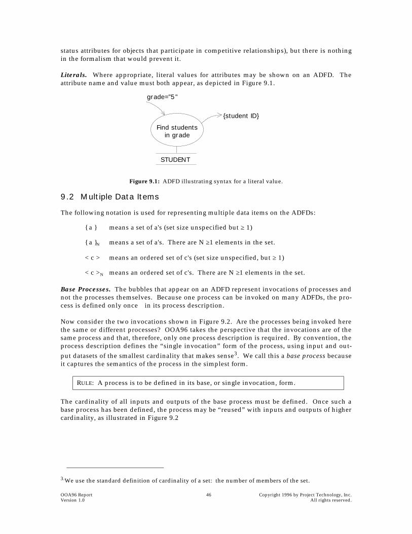
OOA96 Report 46 Copyright 1996 by Project Technology, Inc.Version 1.0 All rights reserved.
status attributes for objects that participate in competitive relationships), but there is nothingin the formalism that would prevent it.
Literals. Where appropriate, literal values for attributes may be shown on an ADFD. Theattribute name and value must both appear, as depicted in Figure 9.1.
Figure 9.1: ADFD illustrating syntax for a literal value.
9.2 Multiple Data Items
The following notation is used for representing multiple data items on the ADFDs:
{ a } means a set of a's (set size unspecified but ≥ 1)
{ a }N means a set of a's. There are N ≥1 elements in the set.
< c > means an ordered set of c's (set size unspecified, but ≥ 1)
< c >N means an ordered set of c's. There are N ≥1 elements in the set.
Base Processes. The bubbles that appear on an ADFD represent invocations of processes andnot the processes themselves. Because one process can be invoked on many ADFDs, the pro-cess is defined only oncein its process description.
Now consider the two invocations shown in Figure 9.2. Are the processes being invoked herethe same or different processes? OOA96 takes the perspective that the invocations are of thesame process and that, therefore, only one process description is required. By convention, theprocess description defines the “single invocation” form of the process, using input and out-put datasets of the smallest cardinality that makes sense3. We call this a base process becauseit captures the semantics of the process in the simplest form.
The cardinality of all inputs and outputs of the base process must be defined. Once such abase process has been defined, the process may be “reused” with inputs and outputs of highercardinality, as illustrated in Figure 9.2
3.We use the standard definition of cardinality of a set: the number of members of the set.
RULE: A process is to be defined in its base, or single invocation, form.
Find studentsin grade
STUDENT
grade="5"
{student ID}

Copyright 1996 by Project Technology, Inc. 47 OOA96 Report All rights reserved. Version 1.0
.
A process derived from a base process is considered to be the same process as the base process.
Finally, OOA defines the concept of cardinality of invocation. The cardinality of an invocationis the number of times the base process must be invoked to produce an equivalent result.
Figure 9.2: The process on the right is derived from the base process on the left.
Parameterized Base Processes. Note that a process appearing with multiple inputs on anADFD is not necessarily a derived process. Consider the process shown in Figure 9.3. Thisprocess cannot be derived from another with fewer inputs, since it produces a single outputregardless of the cardinality of the input dataset. Such a process is considered to be a base pro-cess that has been parameterized to accept an input dataset of any size. When such a process isshown on an ADFD, it is assumed that the process has access to the size of the input dataset;this information is not shown as a separate input to the process.
Figure 9.3: A parameterized base process.
Ordered datasets. When a set of data items are input to a process, it may be necessary to keepthese items ordered in some way so we can make correspondences between them and otherdata items used in subsequent processes, as in Figure 9.4.
Figure 9.4: Example of ordered datasets.
DEFINITION (derived process): A process is said to be derived from a base process if (1) it has the same name, inputs, and outputs and (2) the cardinalities of the input and output data sets bear the same relationship one to another as do the cardinalities of the corresponding datasets of the base process.
Computevolume
height+width+depth
volume
Computevolume
{height+width+depth}
{volume}
Computemean
{X}
X
N
Get cratesfor destination
CRATE
destinationPick
largest
Computevolume
<crate ID> crate ID
<volume><height+width+depth>
N
NN

OOA96 Report 48 Copyright 1996 by Project Technology, Inc.Version 1.0 All rights reserved.
In this example, we do not supply {Crate ID} to the Compute Volume process. Aside from theunaesthetic properties of such a solution, this strategy would mislead during translation and/or impede identification of Compute Volume as a reusable process. Hence:
Iteration and derived processes. If multiple instances of the same data item appear as inputto a derived process, nothing is stated about where any implied iteration takes place. Theplacement of iteration is established when mapping the ADFDs to the architecture. For exam-ple, using the ADFD fragment shown on the right in Figure 9.2, the translation may requireiteration within the process. In such a case, the process will be translated so that it can accepta set of inputs and provide a set of outputs.
state 3::. . .volume ( N, h, w, d, v ). . .
end state 3function volume ( ct, ht, wt, dp, vol)
do k = 1 to ctvol (k) := ht(k)*wt(k)*dp(k)end do
end
Alternatively, the translation may require that the iteration be doneperhaps across severalprocessesin the “state action” module for the entire action:
state 3::. . .do k=1 to Nv(k) = volume ( h(k), w(k), d(k) )end do. . .
end state 3
Finally, on an ADFD exhibiting both multiple instances and conditional output, the analystmust annotate the ADFD to indicate the required scope of iteration. Such an example isshown in Figure 9.5. When the analyst specifies a scope of iteration, the entire group of pro-cesses within the scope will be treated as one for purposes of iteration. As a result, datasetsappearing on dataflows internal to the scope of iteration are of size one.
NOTATION (ordered datasets): Should a dataset need to be ordered for later correspon-dence with other datasets, the dataset appears on the ADFD as <data item>. To spec-ify the cardinality of an ordered dataset, write <data item>N.
RULE (order of input datasets): If a derived process receives as input an ordereddataset, all other input datasets of the same cardinality must be ordered in the sameorder.
RULE (order of output datasets): If a derived process produces as output an ordereddataset, this dataset must be ordered in the same order as any input datasets of thesame cardinality.

Copyright 1996 by Project Technology, Inc. 49 OOA96 Report All rights reserved. Version 1.0
Figure 9.5: An ADFD annotated to indicate the required scope of iteration.
Arrival of output. If multiple instances of the same data item appear as output from a baseprocess, it is assumed that they arrive at any downstream process all at the same time. How-ever, if multiple instances of the same data item appear as output from a derived process, noth-ing is stated at analysis time with respect to whether the data items appear as a set (allbecoming available to the downstream process at the same time) or whether they appear oneby one. This will be established when the scope and placement of the iteration is stated: dur-ing the mapping of the ADFDs to the architecture.
9.3 Process Types
OOA96 allows for exactly four types of processes on an ADFD: accessors, event generators,transformations, and tests.
9.3.1 Accessors
An accessor is now the only process type that can access an object data store. The requiredforms of accessors in OOA96 are shown in Table 9.1. Note that this is the minimum set ofaccessor forms that must be supported by any architectural domain. Should a project wish toprovide additional forms (say, an existence test, or an accessor that can do a compound query),the minimal responsibilities of the architectural domain will have to be expanded.
Find dimensionsof crates boundfor destination
CRATE
destination
Assign crateto plane
CRATEAssign crateto slow boat
CRATE
Computevolume
Find oversizedcrates
<height + width + depth> N
volume
too big
smallenough
<crate ID> N
Scope of iteration

OOA96 Report 50 Copyright 1996 by Project Technology, Inc.Version 1.0 All rights reserved.
Table 9.1: Required Forms for Accessors in OOA96
By examination of Table 9.1, we see that the net flow of data to or from the object data store isentirely determined by the input and the form of the process. Hence, we have an additionalrule:
In order to support self- and non-self-creation, four forms of create accessors have been speci-fied. 'Create' and 'create unique' are to be used for self-creation and creation of passive objects,while 'create in' and 'create unique in' are to be used for non-self creation of active objects.When using either of these two latter forms, the name of the state into which the instance is tobe created is included in the process name, as “create account in 'account established' state”.
Type and form name
Suggested name
Purpose of process Input data flow Output data flow
To/from data store (net flow of data)
Output con-ditional con-trol flow
Read
R1
read Retrieve attribute(s) of specified instance
identifier attr val + . . . + attr val
attr val + . . . + attr val
Read
R2
read where
Retrieve attributes of all instances that meet stated criteria
attr val + . . . + attr val
(criteria)
{attr val + . . . + attr val}N
(result)
{attr val + . . . + attr val}N (result)
(conditional)
no such instances
Read
R3
find where
Retrieve identifiers of all instances that meet stated criteria
attr val+attr val+ . . . +attr val
(criteria)
{identifier}N {identifier}N
(conditional)
no such instances
Write
W1
write Write attribute(s) of specified instance
identifier + attr val + . . . + attr val
attr val + . . . + attr val
Write
W2
write where
Write attributes of all instances that meet stated criteria
attr val + . . . + attr val (criteria) +
attr val + . . . + attr val (result)
{attr val + . . . + attr val}N (result)
(conditional)
no such instances
Create
C1
create Create instance given identifier and, option-ally, attribute values
identifier [+ attr val + . . . + attr val]
identifier [+ attr val + . . . + attr val]
Create
C2
create unique
Create instance given only attribute value(s)
attr val + . . . + attr val
identifier identifier + attr val + . . . + attr val
Create
C3
create in Create instance given identifier, state and, optionally, attribute values
identifier [+ attr val + . . . + attr val]
identifier [+ attr val + . . . + attr val]
Create
C4
create unique in
Create instance given state and attribute value(s)
attr val + . . . + attr val
identifier identifier + attr val + . . . + attr val
Delete
D1
delete Delete instance identifier
Delete
D2
delete where
Delete instances meet-ing stated criteria
attr val + . . . + attr val
instances deleted | no such instances
NOTATION: The net flow of data between an accessor and its data store need not beshown on the ADFD. Alternatively, should a project elect to establish the conventionthat this data flow be labeled, it will be necessary to verify consistency between thedata flow to/from the data store and the inputs and form of the accessor.

Copyright 1996 by Project Technology, Inc. 51 OOA96 Report All rights reserved. Version 1.0
9.3.2 Event Generators
An event generator may only generate one type of event and may not access an object datastore. An event generator may appear on an ADFD as either a base or derived process, asshown in Figure 9.6.
Figure 9.6: An event generator in base and derived forms.
9.3.3 Tests and Transformations
In OOA96, a test or transformation may no longer access an object data store. In addition:
■ A transformation is allowed only to transform datasets. This includes the traditionalcomputational idea behind transformations; it also allows for picking a data value out ofa set (pick the largest volume given a set of volumes, for example).
■ A test is allowed only to test relationships between its inputs.
■ The output of a derived test process is conceptually a set of conditions. The conditionset is of the same relative cardinality as the condition set of the base process.
■ The complete output condition set from a derived test process is not shown on theADFD explicitly. See Figure 9.7 for the proper representation of a derived test.
Figure 9.7: A derived test shows the output condition set as two (or more) subsets.
9.4 Delayed Events and Timers
Timers, as prescribed in OOA91, required the analyst to combine information from the domainunder consideration with the domain of the formalism itself. This situation has been reme-died in OOA96, wherein the functionality previously ascribed to a timer is now associatedwith a new concept: a delayed event. Three processes have been defined to provide therequired functionality. These processes, which are shown in Figure 9.8, may be invoked onany ADFD of any domain.
GenerateV1
valve IDV1: open valve (valve ID)
GenerateV1
{valve ID}{V1: open valve (valve ID)}
Check foroverpressure
{pressure} N
{pressure limit} N
{OK} J
{not OK} N-J

OOA96 Report 52 Copyright 1996 by Project Technology, Inc.Version 1.0 All rights reserved.
Figure 9.8: Timer processes in OOA96.
Canceling a delayed event causes one instance of the delayed event to be canceled. If there aremultiple instances of the specified delayed event outstanding, the event which will be gener-ated soonest will be canceled. If there are no delayed events of the specified type outstanding,nothing happens. Similarly, reading the time until a specified delayed event is to be generatedreturns the time remaining until the next instance of the specified event is to fire. If there areno such events waiting, a time of zero is returned.
9.5 Connecting to Other Domains
9.5.1 The Problem
Although not defined in OOA91, two types of constructs have come into use to connect onedomain to another:
■ bridging process: a process implemented in one domain and invoked on an ADFD asso-ciated with another domain.
■ domain-crossing event: an event that is generated in one domain and received by anobject in another domain.
■ Move Robot is not a process in the same sense as, for example, a test or transformation:Analysts working in the application domain cannot provide an implementable descrip-tion for this process, since they have no knowledge of the inner workings of the PIOdomain.
■ While the intent of the process has been captured in the process name, the requirementson the process may not been stated completely. In many cases, the process would moreproperly be named “move robot and return event 'R2: Robot move complete (robot ID)'when complete.”
■ The nature of the contract between the application and PIO domains may not have beenexamined. The extent of the robot move appears to have been given by the applicationdomain as displacements in x, y, and θ. However, it could equally well have been spec-ified as a new absolute position, and this matter should be carefully considered by theanalysts working on both domains.
Both of these schemes, as currently used, have deficien-cies. In particular, consider the Move Robot bridging pro-cess (from some manufacturing application ADFD) shownto the right. This application uses the services of a Pro-cess InputOutput (PIO) domain for hardware control.
Generate E7 after 10 sec
E ident
CancelE7
E ident
Read timeuntil E7
E ident time remaining
m overobot
d x+dy+dtheta+ robot ID

Copyright 1996 by Project Technology, Inc. 53 OOA96 Report All rights reserved. Version 1.0
■ The destination object is not known to the sender. That is, the key letter here does nothave the same meaning as does the key letter of events internal to a domain.
■ The intent of the communication is captured only partially in the event name. If a return communication is intended, that fact is not recorded on the model.
9.5.2 Wormholes
In OOA96, we use the wormhole symbola double-walled bubbleto indicate a transfer ofcontrol between two domains. The appearance of a wormhole implies specific detailedrequirements on the bridge connecting the two domains. These requirements are madeexplicit in the process description of the “wormhole process” which must include statementsof:
■ What the calling domain (server or client) expects the other domain to do (stated in thesemantic world of the caller).
■ Any return communication required by the caller.
In the general case, the analyst cannot determine whether the wormhole represents an acces-sor, event generator, test, or transformationor, in fact, a connected set of such processes.This will be determined during design when the wormholes are finally resolved.
Finally, note that the appearance of a wormhole on an ADFD does not prescribe whether thecommunication between the domains is implemented via a synchronous or an asynchronousmechanism. This matter will also be determined when the wormholes are resolved and thebridge connecting the two domains is developedgenerally shortly prior to translation.
9.6 Particular Constructs
Common processing after conditional flows. Occasionally, after a test or other process thatmakes conditional output, one wishes to indicate common processing on an ADFD. This canbe done by merging the data (or control) flows as shown schematically in Figure 9.9.
Now let us consider a domain-crossing event as shown inthe figure to the right. This event is generated by the appli-cation domain and intended to be received in the alarmdomain. This “event”, like the bridging “process”, is notwhat it seems:
ge ne rateev en t A 1to ala rmdo m ain
tra in ID + d erail lo ca tio n
A 1 : d era ilm e nt a la rm(train ID , dera il lo ca tion )

OOA96 Report 54 Copyright 1996 by Project Technology, Inc.Version 1.0 All rights reserved.
Figure 9.9: An ADFD with a merge and the corresponding defining ADFD.
A merge is considered to be only a representational shorthand: its meaning is defined by anADFD that shows the common processing replicated wherever it is to occur. Such a “defin-ing” ADFD cannot show any merges.
For an ADFD with a merge, it is the responsibility of the analyst to verify that only one of theprocesses that produces the merged output can execute by nature of the topology of the entireADFD.
OK
A
D
not OKB ...
C
E
F
Y
Y
OK
A
D
not OKB ...
C
E
F
Y Y
E
F