shocks n vibrations
TRANSCRIPT

8/12/2019 shocks n vibrations
http://slidepdf.com/reader/full/shocks-n-vibrations 1/10
AADE-07-NTCE-47
Real-Time Stick-Slip and Vibration Detection for 8 ½”-Hole-SizeRotary Steerable Tools in Deeper Wells and More Aggressive Drilling
Junichi Sugiura, Steve Jones — PathFinder Energy Services
Copyright 2007, AADE
This paper was prepared for presentation at the 2007 AADE National Technical Conference and Exhibition held at the Wyndam Greenspoint Hotel, Houston, Texas, April 10-12, 2007. This conferencwas sponsored by the American Association of Drilling Engineers. The information presented in this paper does not reflect any position, claim or endorsement made or implied by the America Association of Drilling Engineers, their officers or members. Questions concerning the content of this paper should be directed to the individuals listed as author(s) of this work.
AbstractIn an extended-reach and horizontal well drilling
environment, stick-slip becomes increasingly problematic with
smaller-diameter and longer drillstrings. Surface detection of
the bottom-hole assembly stick-slip and vibration becomesever more difficult. A Real-time Stick-slip and Vibration
Detection (RSVD) system was incorporated into a new 8 ½-
inch-hole-size Rotary Steerable System (RSS), to increase
drilling efficiency in deep wells and to protect the RSS and theMWD/LWD tools from harmful vibrations.
This RSVD system is an innovative near-bit vibration
sensor integrated into the RSS, featuring detection of the three
principal modes of drillstring vibration — torsional, lateraland axial. The sensor is located 8.2 feet above the bit in the
push-the-bit configuration and 11.1 feet above the bit in the
point-the-bit configuration. The system sends the detectedstick-slip severity to the surface in real time so that operators
can change drilling parameters if harmful downhole conditions
are detected.In 2006, the new sensor system was extensively tested
and proved to be effective with the new 8 ½”-hole-size RSS in
various wells, including vertical and horizontal, both onshoreand offshore. This paper will discuss the harmful stick-slip
and vibration conditions in smaller-hole-size wells and how
the RSVD system improved penetration rate and prolongedthe optimum performance of the drill bit, BHA, MWD/LWD,
and rotary steerable tool in various situations.
IntroductionResearch on drillstring dynamics has been extensively
conducted in the past [1-4]. In the 1980’s and 1990’s,drillstring dynamics MWD sensors were developed to detect
and record harmful downhole vibrations [5-16]. Today, it is
well known that severe downhole vibrations can damage
drilling equipment including the drill bit, drill collars,stabilizers, MWD/LWD, and Rotary Steerable System (RSS).In 1997, the first introduction of the commercial RSS
revolutionized directional drilling [17]. Since then, RSS
technology has made remarkable improvements in reliabilityand has become a mature, standard application. Nevertheless,
due to its inherent complexity, the reliability of the RSS is still
lower than that of MWD and LWD tools [18].
In 2005, PathFinder developed a new RSS for 8 ½” holesize, based on proven 12 ¼”-hole-size RSS technology, for
drilling more challenging extended-reach and horizontal wells
The new RSS consists of a non-rotating housing with threeactive and independent blades that maintain constant contac
with the wellbore. Directional steering is achieved by
positioning the blades to offset the tool center from thecenterline of the hole. Therefore, the system drills a
continuous curve and does not rely upon on/off biasing. The
constant contact of the blades with the borehole provides near
bit caliper measurements and, moreover, extra stability to thelower part of the bottom-hole assembly (BHA) hence reducingundesirable drill bit vibrations and instability [19].
Despite the extra stability gained at the RSS, it is
inevitable that the tool is exposed to high vibrations due to, forexample, torsional vibration (stick-slip) induced from the bit-
formation interaction [2,11,13], lateral vibrations caused by
the mass imbalance of drill collars and other BHA component[12,20], and axial vibrations resulting from the high-low
pattern of a rock bit in hard formation [1,14]. Moreover, some
of these vibrations do not travel to the surface.Thus, Real-time Stick-slip and Vibration Detection has
been incorporated into the newly developed 8 ½”-hole-size
RSS. The new sensor system is designed to detect near-bivibration at the RSS. Timely remedies to harmful vibrations
can protect MWD/LWD and the RSS from such vibrations and
increase drilling efficiency [16,20-24]. With the RSVDsystem, the operator can be aware of harmful downhole
conditions and can adjust surface parameters, such as RPM
WOB and flow rate, to optimize the drilling performanceThis system is a unique near-bit vibration sensor integrated
into the RSS, featuring the detection of three principal modes
of the drillstring vibration, namely torsional, lateral and axial.
Design Concept The Real-time Stick-slip and Vibration Detection system
has been integrated into the new 8 ½-inch-hole-size RSS tooto detect harmful downhole vibrations. The new sensosystem utilizes the existing hardware (rotation and vibration
sensors) of the RSS to quantify the severity of downhole
torsional (stick-slip), lateral and axial vibrations.Figure 1 shows the 8 ½”-hole-size point-the-bit RSS with
the RSVD system. All three principal modes of the drillstring
vibration are detected at the RSS and classified into 4
categories of severity for the band-limited mud pulse
telemetry. Also, this classification produces effective data

8/12/2019 shocks n vibrations
http://slidepdf.com/reader/full/shocks-n-vibrations 2/10
2 Junichi Sugiura, Steve Jones AADE-07-NTCE-47
compression. The new sensor system is designed to be used
for all the RSS runs. Therefore, it is crucial that uplink
communication bandwidth of the vibration information beminimum.
The Stick-slip Severity (SS%) is computed from the drill
bit rotation sensor and expressed as:
%100% ×Δ= MeanRPM
RPM SS …. Equation 1
The drill bit rotation variation (ΔRPM) is normalized with
an average rotation rate (MeanRPM) of the drill bit. Dufeyteet al. first used a similar equation for the surface detection of
the stick-slip phenomenon [8]. The SS% is further classifiedinto 4 different severity levels.
Table 1 below shows the stick-slip level, classification,
and percentage severity. Stick-slip levels between 0 and 3 are
sent to the surface via mud pulse telemetry.
Table 1. Stick-Slip level, classification and percentage severity
Stick-Slip Level Stick-Slip Classification SS %0 Very Low 0 ~ 50%
1 Low 50% ~ 100 %
2 Medium 100 % ~ 150 %
3 High 150 % or more
The Lateral Vibration Severity (Vibxy%) is computed
from the x- and y-axis acceleration sensors and expressed as:
%100% ××Δ= ScaleVibVib xy xy … Equation 2
The lateral vibration fluctuation (Δ Vibxy) is scaled andconverted into percentage severity (Vibxy%). The scale factor
in Equation 2 was fine-tuned through extensive field tests
where the correlation between vibration levels and the RSS
dysfunctions was identified.
Similarly, the Axial Vibration Severity (Vibz%) iscomputed from the z-axis acceleration sensor and expressed
as:
%100% ××Δ= ScaleVibVib z z … Equation 3
These lateral and axial vibration severities, in percentage,
are classified into 4 categories as in the stick-slip level.Table 2 below shows the vibration level and classification.
Vibration levels between 0 and 3 are sent to the surface via
mud pulse telemetry.Table 2. Vibration level, classification and percentage severity
Vibration Level Vibration Classification Vib %
0 Very Low 0 ~ 25%
1 Low 25% ~ 50 %
2 Medium 50 % ~ 75 %
3 High 75 % or more
Since the RSVD system utilizes the existing hardware of
the RSS, the new sensor has added no extra complexity into
the RSS. Moreover, this design approach enables a costeffective near-bit dynamics sensor, which is presently a
standard component of all PathFinder’s rotary steerable tools.
The system also transmits the detected severity to the
surface with real-time mud pulse telemetry so that operators
can change drilling parameters if harmful downhole vibrationare detected. This feature, along with the near-bit calipe
measurement, resulted in increased overall reliability and performance of the RSS and other drilling equipment.
Detected Downhole Vibration Problems PathFinder has conducted a series of extensive field tests
with the 8 ½”-hole-size rotary steerable systems (RSS) in2005 and 2006. The new RSS, along with the RSVD feature
detected various downhole vibration conditions. This section
shows some of the most commonly observed harmfu
vibration cases. When a downhole failure occurred, vibrationinformation stored in memory was used for more detailed
post-run analysis, the root cause of the failure was
investigated, and the failed component was redesigned for
more durability.
Full-Stall Stick-SlipFigures 2 and 3 illustrate the full-stall stick-slip observed
on a rig in the Gulf of Mexico while drilling in a “ratty”
abrasive sandstone section with the 8 ½”-hole-size RSS. Postdrilling LWD data analysis showed that this section was
composed of high salinity siltstone, shale, and sand. Very slow
drilling (low ROP) and high/erratic string torque between 10to 25K ft-lb were encountered.
Figure 2 shows surface parameters/data during downhole
full-blown stick-slip. Figure 3 shows downhole-computedmean and raw RPM vs. blade housing toolface angle. It i
noticed that rotary torque correlated highly with the downhole
stick-slip data while the WOB was kept nearly constant. TheSet_RPM is the programmed surface RPM that is different
from the actual surface RPM (not shown).
In Figure 3, the slowly changing BL1_TF (blade housingtoolface angle between 140 and 170 degrees) indicates that the
non-rotating blade housing was substantially stationary as
compared with the drillstring rotation (about 120 RPM)During the stick-slip period, the maximum raw RPM (240 ~
360 RPM) was 2 or 3 times higher than the surface RPM (≈120 RPM). The corresponding Stick-slip Severity (SS%) in
the period is approximately between 200% and 300%.
Polycrystalline Diamond Compact Bit Comparison
Figures 4 and 6 show the examples of bit-formationinduced stick-slip on the 8 ½”-hole-size RSS observed inOklahoma. Mean_RPM, Raw_RPM, and BL1_TF represen
average near-bit RPM, raw near-bit RPM, and Blade 1
toolface, respectively. The slowly changing BL1_TF indicatethat non-rotating blade housing is substantially stationary.
A 7-bladed bit with 13mm (1/2-in) PDC cutters shown in
Figure 5 was used in the run (Run # 16). This PDC bit (with1.5” active gauge) produced ROP less than 9 feet/hour and the
decision was made to change for a more aggressive drill bit to

8/12/2019 shocks n vibrations
http://slidepdf.com/reader/full/shocks-n-vibrations 3/10
AADE-07-NTCE-47 Real-Time Stick-Slip and Vibration Detection for 8 ½”-Hole-Size Rotary Steerable Tools 3
increase ROP.A 6-bladed bit with 16mm (5/8-in) PDC cutters shown in
Figure 7 was used in this run (Run # 17). This bit (with 3”
passive gauge) produced an average ROP of 15 feet/hour. The
ROP was almost doubled while the formation and the surface
parameters were practically identical. However, with a moreaggressive bit, near-bit RPM varied roughly by ± 40 RPM
(Stick-Slip Severity was about 72%). This stick-slip problem became worse while drilling through different formations and
eventually resulted in premature failure of the RSS.This is a classical case in which the optimization for
maximum penetration rate resulted in damage to the drilling
equipment, thus a costly trip (round trip) and non-productivetime (down time) due to vibration-related premature failure.
PDC and Rock Bit ComparisonThe GTI Test Facility in Catoosa, Oklahoma was used to
evaluate the prototype 8 ½”-hole-size RSS for performance,ruggedness and reliability. Figures 8 shows real-time MWD
and RSS vibration data collected at the GTI facility, including
the surface parameters. The MWD vibration data wasmeasured approximately 45 feet above the bit, providing the
number of vibration counts above 20 G per second.
Vibration profiles between a PDC and a rock bit (a rollercone bit) are compared using the RSVD system. The PDC bit
induced more lateral vibrations, whereas the rock bit produced
more axial vibrations. The real-time vibration data (Lateral
Vibration = Low and Axial Vibration = Low) obtained withthe RSVD system at the RSS correlated highly with the
vibration counts (≈ 100 counts/second … considered as a low
vibration count) detected at the conventional MWD tool.
While drilling though a hard dolomite section, called the
Arbuckle group (not shown), this BHA suffered from highvibration counts (≈ 450 counts/second) and high near-bit
lateral vibration at the RSS. This vibration problemeventually resulted in RSS failure.
Lateral Vibration due to Mass ImbalanceAt the GTI Catoosa facility, medium-to-high vibration
severity was detected with both MWD and the RSVD system
while the 8 ½”-hole-size RSS was drilling in a dolomitesection. The Run #1 BHA was initially configured for drilling
a high-inclination well (i.e. a horizontal well). 20 joints of 5”
heavy-weight drill pipe (HWDP) were used below 10 joints of6 ¼” drill collars. Figure 9 shows high lateral and axial
vibrations at the RSS in Run #1. The near-bit caliper
measurement indicated that hole was in gauge, between 8.54”
and 8.56.” The near-bit RPM measurement was steady atapproximately 100 RPM. There was no sign of stick-slip
phenomenon (SS3D = 0). The slowly changing BL1_TF
indicated that the non-rotating blade housing was substantiallystationary, providing additional stability to the BHA. At this
point, the exact cause of the vibration problem was unknown.
Long and repetitive exposure to excessive shock and
vibration is harmful to the RSS and, in the worst case,
catastrophic. Thus, different surface parameters were variedto reduce vibrations using the RSVD information, but all
attempts ended unsuccessfully. The decision was made to pulout the tool to change the position of drill collars and heavy-
weight drill pipe (HWDP). The BHA order was inverted, fo
example, 10 joints of 6 ¼” drill collars were run below 20
joints of 5” HWDP. At the same time, the onset of drillingequipment damage was discovered and repaired at the rig site.
While repairing, a back-up tool with a rock bit was used
in Run #2 (not shown) without BHA modification to seewhether the rock bit reduced excessive vibration. This bi
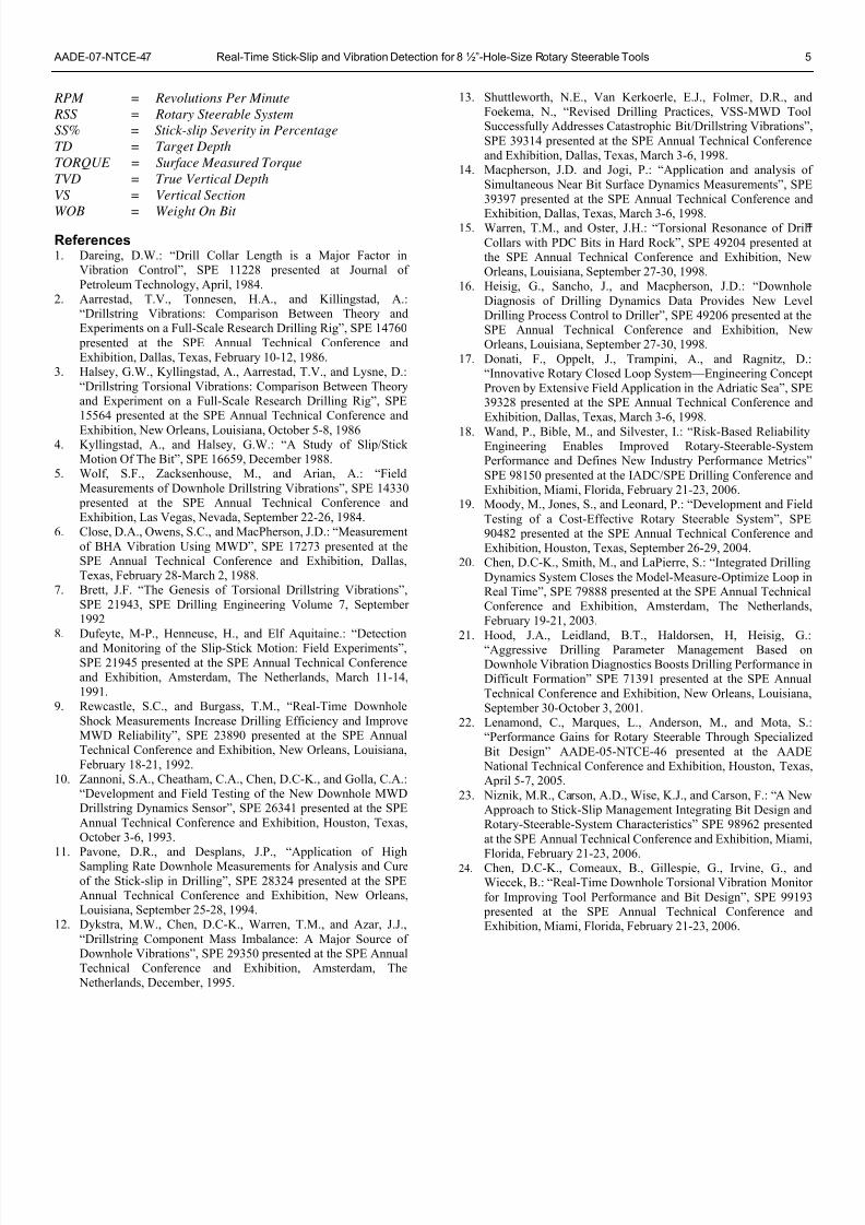
change did not reduce vibration.In Run #3, the repaired tool from Run #1 with the BHA
modification was tripped in and commenced drilling. Figure
10 shows that the RSS vibration in Run #3 was reduced byalmost half from Run #1 while the same RPM and WOB were
used. In both runs, the borehole inclination was between 19
and 20 degrees. The formation drilled in Run #3 was simila
to that of Run #1.Figure 11 shows the surface parameters and the real-time
data measured with the RSVD system. Both lateral and axia
vibration severity levels were suppressed to Level 1 (Low
Severity). Moreover, the real-time MWD vibration countswere reduced from 300 CPS to 50 CPS. It was concluded tha
BHA mass imbalance and BHA instability created high latera
vibrations in Run #1.
Customer Well ResultsIn 2005 and 2006, the RSVD system integrated into the
8½”-hole-size RSS was extensively tested in various customer
wells in North America, including vertical and horizontawells, onshore and offshore. As of December 25, 2006, the
newly designed 8 ½”-hole-size RSS has drilled 42,055 feet
accumulating 1,738 operating hours. Throughout the
commercial pilot runs, the real-time drilling screen wasavailable to a multi-disciplinary drilling optimization team
consisting of a Directional Drilling Engineer, an RSSOptimization Engineer, a Research Engineer and a DesignEngineer. Remote satellite communication and Interne
technologies enabled the team to monitor the downhole
drilling conditions around the clock. This team providedcritical feedback to the on-site Directional Drillers and MWD
Engineers for minimizing vibration-related failures and for
improving drilling efficiencies.
The following section discusses how the RSVD system
improved ROP and prolonged the optimum performance ofthe drill bit, BHA, MWD/LWD, and rotary steerable tool in
three examples of customer wells.
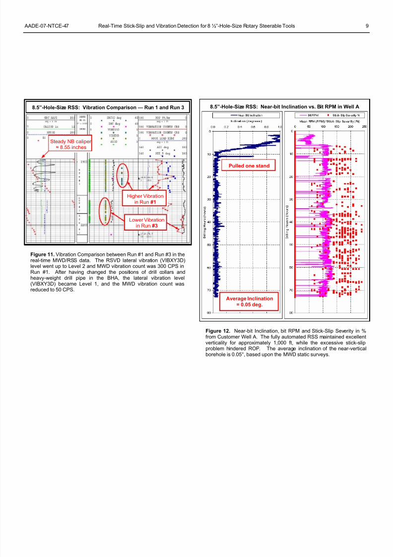
Well AThe vertical section of an S-shape well was drilled with
the fully automated 8 ½”-hole-size RSS in Texas. The
borehole inclination was originally 1.06 degrees. The RSS
quickly dropped the inclination back to less than 0.1° andmaintained the inclination to an average value of 0.05° for
approximately 1,000 ft. The average inclination of the near
vertical borehole was based upon the MWD static surveys
No time was wasted downlink programming the RSS in thisvertical drilling application as the RSS was set up to

8/12/2019 shocks n vibrations
http://slidepdf.com/reader/full/shocks-n-vibrations 4/10
4 Junichi Sugiura, Steve Jones AADE-07-NTCE-47
continuously seek low-side. Several rig repairs were carriedout during 3 days, adding non-productive time. The overall
penetration rate in the vertical section was 14.1 ft/hr.
While drilling, the RSVD revealed that excessive stick-
slip hindered ROP on this well. Figure 12 shows the near-bit
inclination, bit RPM and Stick-slip Severity in % computed atthe RSS. The downhole computer applies a low-pass filter to
raw RPM readings and records a mean RPM in memory. Itwas noticed that the filtered RPM was still noisy due to stick-
slip.The RSS assembly was pulled for low ROP and a
suspected undergauge bit. At surface, bit and near-bit
stabilizer were both undergauge. The following run was aconventional steerable motor with a similar PDC bit. This
assembly averaged 23 ft/hr indicating that stick-slip was
causing the low ROP. In this application, the use of a motor-
assisted RSS assembly would have reduced stick-slip at the bitand ultimately led to improved ROP.
Well BThe 8 ½”-hole-size RSS was used with a small under-
powered rig in New Mexico. The RSS drilled 3,260 ft at an
ROP of 39.7 ft/hr, accumulating 82.2 drilling hours and 164.2
circulating hours. WOB was maintained at 15,000 to 20,000lbs. No major vibrations were observed in the first half of the
run as shown in Figure 13. In the second half, stick-slip
became problematic with Stick-slip Severity between 100%
and 200%. Very little lateral and axial vibrations were
observed in the real-time data. The RSS operators were ableto manage the stick-slip problem and completed 1,700 ft of the
problematic footage without downhole failure.
These wells are typically drilled at an average ROP of 15
ft/hr with a conventional steerable motor and rock bit (forsteerability). The use of RSS and PDC bit provided a 164%
increase in ROP.
Well CThe 8 ½”-hole-size RSS was used on the build section of
a Fayette Shale well. The well plan called for 8°/100ft build
rates to land in the reservoir at 92 degrees as shown in Figure
14. Due to rig rotary speed (RPM) limitations, this well wasdrilled with the RSS below a slow-speed downhole motor and
a PDC bit. The well was kicked off and built angle at 8°/100ft
using an 80% offset setting. The RSS offset setting wasreduced as the angle increased to maintain the desired 8°/100ft
build rates. Both stick-slip and vibration were low throughout
the run as a result of using the motor-assisted RSS assembly.
The assembly drilled 1,404 ft at an average ROP of 55 ft/hr.Typically these wells are drilled at an average ROP of 30
ft/hr with a conventional steerable motor and rock bit (for
steerability). The use of motor-assisted RSS and PDC bit
produced an 83% increase in ROP and a significant reductionin stick-slip and vibration.
Conclusion
• The Real-time Stick-slip and Vibration Detection system
integrated into the newly designed 8 ½”-hole-size RSS, is a
cost-effective near-bit vibration sensor, which is now a
standard component of all tools. The sensor system waeffective for detecting various downhole dynamic
conditions in real time.
• The real-time near-bit stick-slip and vibration data, along
with near-bit caliper measurements, is always available to
Directional Drillers and MWD Engineers while drillingcomplex 3D wells using an RSS. The sensor system lead
to optimized drilling parameters in most of the RSS runs
by avoiding under-utilization of the vibration information.
• The customer well results indicated that the RSVD feature
helps minimize the detrimental effect of downhole
vibrations and prolong optimum performance of the RSS
and other BHA components. The effective use of thesensor system resulted in increased reliability of the RSS.
• The use of aggressive bits and aggressive drilling
parameters do not necessarily increase the overall ROP due
to increased chance of downhole failures and consequentlyincreased non-productive down time.
• The use of less aggressive but stable bits and optimized
drilling parameters with manageable vibration levels helpsimprove the overall ROP and reduce downhole failures.
• The use of motor-assisted RSS and PDC bit reduces stick-slip and vibration and further improves penetration rate.
• The improved drilling performance and time/cost saving
obtained with the RSVD feature are significant.
AcknowledgmentsThe authors would like to thank the different operation
companies for their willingness to field-test the 8½”-hole-sizePathMaker ® rotary steerable tool and to allow us to use the
data presented here. We are grateful to PathFinder Energy
Services for permitting the publication of this work.
Nomenclature BHA = Bottom Hole Assembly
CPS = Counts Per Second
DLS = Dogleg Severity (degrees per 100 feet)GPM = Gallons Per Minute
HWDP = Heavy-Weight Drill Pipe
LWD = Logging While Drilling
MD = Measured Depth
MWD = Measurement While Drilling
NB = Near Bit
PDC = Polycrystalline Diamond Compact
ROP = Drilling Rate Of Penetration
8/12/2019 shocks n vibrations
http://slidepdf.com/reader/full/shocks-n-vibrations 5/10
AADE-07-NTCE-47 Real-Time Stick-Slip and Vibration Detection for 8 ½”-Hole-Size Rotary Steerable Tools 5
RPM = Revolutions Per Minute
RSS = Rotary Steerable System
SS% = Stick-slip Severity in Percentage
TD = Target Depth
TORQUE = Surface Measured Torque
TVD = True Vertical Depth
VS = Vertical Section
WOB = Weight On Bit =15. Warren, T.M., and Oster, J.H.: “Torsional Resonance of Dril
Collars with PDC Bits in Hard Rock”, SPE 49204 presented athe SPE Annual Technical Conference and Exhibition, NewOrleans, Louisiana, September 27-30, 1998.
References1. Dareing, D.W.: “Drill Collar Length is a Major Factor in
Vibration Control”, SPE 11228 presented at Journal of
Petroleum Technology, April, 1984.2. Aarrestad, T.V., Tonnesen, H.A., and Killingstad, A.:
“Drillstring Vibrations: Comparison Between Theory andExperiments on a Full-Scale Research Drilling Rig”, SPE 14760
presented at the SPE Annual Technical Conference andExhibition, Dallas, Texas, February 10-12, 1986.
3. Halsey, G.W., Kyllingstad, A., Aarrestad, T.V., and Lysne, D.:
“Drillstring Torsional Vibrations: Comparison Between Theoryand Experiment on a Full-Scale Research Drilling Rig”, SPE15564 presented at the SPE Annual Technical Conference and
Exhibition, New Orleans, Louisiana, October 5-8, 19864. Kyllingstad, A., and Halsey, G.W.: “A Study of Slip/Stick
Motion Of The Bit”, SPE 16659, December 1988.5. Wolf, S.F., Zacksenhouse, M., and Arian, A.: “Field
Measurements of Downhole Drillstring Vibrations”, SPE 14330 presented at the SPE Annual Technical Conference andExhibition, Las Vegas, Nevada, September 22-26, 1984.
6. Close, D.A., Owens, S.C., and MacPherson, J.D.: “Measurement
of BHA Vibration Using MWD”, SPE 17273 presented at theSPE Annual Technical Conference and Exhibition, Dallas,Texas, February 28-March 2, 1988.
7. Brett, J.F. “The Genesis of Torsional Drillstring Vibrations”,
SPE 21943, SPE Drilling Engineering Volume 7, September1992
8. Dufeyte, M-P., Henneuse, H., and Elf Aquitaine.: “Detection
and Monitoring of the Slip-Stick Motion: Field Experiments”,SPE 21945 presented at the SPE Annual Technical Conferenceand Exhibition, Amsterdam, The Netherlands, March 11-14,1991.
9. Rewcastle, S.C., and Burgass, T.M., “Real-Time Downhole
Shock Measurements Increase Drilling Efficiency and ImproveMWD Reliability”, SPE 23890 presented at the SPE AnnualTechnical Conference and Exhibition, New Orleans, Louisiana,
February 18-21, 1992.10. Zannoni, S.A., Cheatham, C.A., Chen, D.C-K., and Golla, C.A.:
“Development and Field Testing of the New Downhole MWDDrillstring Dynamics Sensor”, SPE 26341 presented at the SPE
Annual Technical Conference and Exhibition, Houston, Texas,October 3-6, 1993.
11. Pavone, D.R., and Desplans, J.P., “Application of HighSampling Rate Downhole Measurements for Analysis and Cure
of the Stick-slip in Drilling”, SPE 28324 presented at the SPEAnnual Technical Conference and Exhibition, New Orleans,Louisiana, September 25-28, 1994.
12. Dykstra, M.W., Chen, D.C-K., Warren, T.M., and Azar, J.J.,
“Drillstring Component Mass Imbalance: A Major Source ofDownhole Vibrations”, SPE 29350 presented at the SPE AnnualTechnical Conference and Exhibition, Amsterdam, The
Netherlands, December, 1995.
13. Shuttleworth, N.E., Van Kerkoerle, E.J., Folmer, D.R., andFoekema, N., “Revised Drilling Practices, VSS-MWD TooSuccessfully Addresses Catastrophic Bit/Drillstring Vibrations”
SPE 39314 presented at the SPE Annual Technical Conferenceand Exhibition, Dallas, Texas, March 3-6, 1998.
14. Macpherson, J.D. and Jogi, P.: “Application and analysis o
Simultaneous Near Bit Surface Dynamics Measurements”, SPE39397 presented at the SPE Annual Technical Conference and
Exhibition, Dallas, Texas, March 3-6, 1998.
16. Heisig, G., Sancho, J., and Macpherson, J.D.: “Downhole
Diagnosis of Drilling Dynamics Data Provides New LeveDrilling Process Control to Driller”, SPE 49206 presented at theSPE Annual Technical Conference and Exhibition, NewOrleans, Louisiana, September 27-30, 1998.
17. Donati, F., Oppelt, J., Trampini, A., and Ragnitz, D.“Innovative Rotary Closed Loop System—Engineering ConcepProven by Extensive Field Application in the Adriatic Sea”, SPE39328 presented at the SPE Annual Technical Conference andExhibition, Dallas, Texas, March 3-6, 1998.
18. Wand, P., Bible, M., and Silvester, I.: “Risk-Based ReliabilityEngineering Enables Improved Rotary-Steerable-SystemPerformance and Defines New Industry Performance Metrics”
SPE 98150 presented at the IADC/SPE Drilling Conference andExhibition, Miami, Florida, February 21-23, 2006.
19. Moody, M., Jones, S., and Leonard, P.: “Development and Field
Testing of a Cost-Effective Rotary Steerable System”, SPE90482 presented at the SPE Annual Technical Conference andExhibition, Houston, Texas, September 26-29, 2004.
20. Chen, D.C-K., Smith, M., and LaPierre, S.: “Integrated Drilling
Dynamics System Closes the Model-Measure-Optimize Loop inReal Time”, SPE 79888 presented at the SPE Annual TechnicaConference and Exhibition, Amsterdam, The NetherlandsFebruary 19-21, 2003.
21. Hood, J.A., Leidland, B.T., Haldorsen, H, Heisig, G.“Aggressive Drilling Parameter Management Based onDownhole Vibration Diagnostics Boosts Drilling Performance inDifficult Formation” SPE 71391 presented at the SPE Annual
Technical Conference and Exhibition, New Orleans, LouisianaSeptember 30-October 3, 2001.
22. Lenamond, C., Marques, L., Anderson, M., and Mota, S.“Performance Gains for Rotary Steerable Through Specialized
Bit Design” AADE-05-NTCE-46 presented at the AADE National Technical Conference and Exhibition, Houston, TexasApril 5-7, 2005.
23. Niznik, M.R., Carson, A.D., Wise, K.J., and Carson, F.: “A NewApproach to Stick-Slip Management Integrating Bit Design andRotary-Steerable-System Characteristics” SPE 98962 presented
at the SPE Annual Technical Conference and Exhibition, Miami
Florida, February 21-23, 2006.24. Chen, D.C-K., Comeaux, B., Gillespie, G., Irvine, G., andWiecek, B.: “Real-Time Downhole Torsional Vibration Monito
for Improving Tool Performance and Bit Design”, SPE 99193 presented at the SPE Annual Technical Conference andExhibition, Miami, Florida, February 21-23, 2006.

8/12/2019 shocks n vibrations
http://slidepdf.com/reader/full/shocks-n-vibrations 6/10
6 Junichi Sugiura, Steve Jones AADE-07-NTCE-47
Figure 1. The Real-time Stick-slip and Vibration Detection (RSVD)system integrated into the 8 ½-inch-hole-size RSS in a point-the-bitconfiguration. The RSVD sensor is located 11.1 feet above the bit inthe point-the-bit RSS. The real-time near-bit caliper is measured 8.2feet above the bit. Optionally, a Pay-Zone Steering module isplaced at the bit for inclination, RPM and Gamma Raymeasurement.
Flex Collar
Lower Shaft Sub
Control Chassis
Non-rotatingBlade Housing
Near-Bit Stabilizer
Drill Bit
External Internal
Pressure SensorWireless Datalink
Blade AssemblyReal-time Caliper
Rotation and Vibration Sensors
Electronics and Hydraulics(i.e. Inclinometers)
The RSVD System
Optional At-bit Inclination,RPM and Gamma Ray
Figure 2. Surface parameters/data during downhole full-blown stick-slip. Notice that rotary torque fluctuation correlated highly with thedownhole near-bit stick-slip data in the figure below while the WOBwas kept nearly constant. The Set_RPM is the programmed surfaceRPM that is different from the actual surface RPM. It is noticed in theabove figure that stick-slip tends to reduce ROP.
Figure 3. Downhole mean and raw RPM vs. blade housing toolfaceangle (BL1_TF). The slowly changing BL1_TF (140 ~ 170 degrees)indicates the non-rotating blade housing was substantially stationary,compared with the mean drillstring rotation (about 120 RPM). Theraw RPM variations between 0 RPM and 380 RPM indicate the onsetof a full-stall stick-slip. The corresponding Stick-slip Severity (SS%)in the period is approximately between 200% and 300%.

8/12/2019 shocks n vibrations
http://slidepdf.com/reader/full/shocks-n-vibrations 7/10
AADE-07-NTCE-47 Real-Time Stick-Slip and Vibration Detection for 8 ½”-Hole-Size Rotary Steerable Tools 7
Figure 4. Low RPM variations with a 7-bladed bit with 13mm PDCcutters. The average ROP was reported as 8.2 ft/hr. The slowlychanging BL1_TF (119 ~ 219 degrees) indicates the non-rotatingblade housing was substantially stationary, compared with the meandrillstring rotation (about 120 RPM).
Figure 5. The less aggressive PDC bit used in the above run.This picture was taken after the above run.
Figure 6. High RPM variations (Stick-Slip Severity ≈ 72%) with a 6-bladed bit with 16mm PDC cutters. The average ROP was reportedas 14.2 ft/hr. The slowly changing BL1_TF (20 ~ 260 degrees)indicates the non-rotating blade housing was substantiallystationary, compared with the mean drillstring rotation (about 115RPM).
7-bladed w/ 13mm PDC 6-bladed w/ 16mm PDC
Figure 7. The more aggressive PDC bit used in the above run.This picture was taken before the above run.

8/12/2019 shocks n vibrations
http://slidepdf.com/reader/full/shocks-n-vibrations 8/10
8 Junichi Sugiura, Steve Jones AADE-07-NTCE-47
Figure 8. Vibration Comparison between PDC and Rock bit in thereal-time MWD/RSS data. Lateral vibration (VIBXY3D = 1) wasdominant while drilling with a PDC bit. In contrast, axial vibration(VIBZ3D = 1) was dominant with a rock bit.
Figure 9. Relatively high lateral and axial vibrations (Vibxy and Vibz)measured in Run #1. The slowly changing BL1_TF (50 ~ 140degrees) indicates the non-rotating blade housing was substantiallystationary, compared with the mean drillstring rotation (about 99RPM).
Figure 10. Lower lateral and axial vibrations (Vibxy and Vibz)measured in Run #3. The downhole near-bit vibrations were reducedby almost half from Run #1 after having changed the positions of drillcollars and heavy-weight drill pipe in the BHA. The slowly changingBL1_TF (10 ~ 70 degrees) indicates the non-rotating blade housingwas substantially stationary, compared with the mean drillstringrotation (about 101 RPM).
Steady Downhole RPM (≈ 99 RPM)
Steady Near-bit Caliper (≈ 8.55”)
Steady Downhole RPM (≈ 101 RPM)
Steady Near-bit Caliper (≈ 8.55”)
Slowly Changing Blade 1 Toolface
PDC Bit
Rock Bit
Steady NB caliper≈ 8.55 inches
8.5” RSS: Bit Vibration Comparison in Catoosa-Hole-Size
8/12/2019 shocks n vibrations
http://slidepdf.com/reader/full/shocks-n-vibrations 9/10
AADE-07-NTCE-47 Real-Time Stick-Slip and Vibration Detection for 8 ½”-Hole-Size Rotary Steerable Tools 9
Figure 11. Vibration Comparison between Run #1 and Run #3 in thereal-time MWD/RSS data. The RSVD lateral vibration (VIBXY3D)level went up to Level 2 and MWD vibration count was 300 CPS inRun #1. After having changed the positions of drill collars andheavy-weight drill pipe in the BHA, the lateral vibration level(VIBXY3D) became Level 1, and the MWD vibration count wasreduced to 50 CPS.
8.5”-Hole-Size RSS: Near-bit Inclination vs. Bit RPM in Well A8.5”-Hole-Size RSS: Vibration Comparison — Run 1 and Run 3
Figure 12. Near-bit Inclination, bit RPM and Stick-Slip Severity in %from Customer Well A. The fully automated RSS maintained excellentverticality for approximately 1,000 ft, while the excessive stick-slipproblem hindered ROP. The average inclination of the near-verticalborehole is 0.05°, based upon the MWD static surveys.
Steady NB c ≈ 8.55
aliperinches
Pulled one stand
Average Inclination= 0.05 deg.
Lower Vibrationin Run #3
Higher Vibrationin Run #1

8/12/2019 shocks n vibrations
http://slidepdf.com/reader/full/shocks-n-vibrations 10/10
10 Junichi Sugiura, Steve Jones AADE-07-NTCE-47
Figure 13. Comparison plot of Planned (red) versus Actual (blue)well path from Customer Well B. The RSS drilled 3,260 ft at anaverage ROP of 39.7 ft/hr without downhole failure. WOB wasmaintained at 15,000 to 20,000 lbs. The RSVD detectedsignificant stick-slip in the second half of the well path up to the TDat X365.7 MD.
Figure 14. Actual well path drilled in Customer Well C. The RSS
was used on the build section of a Fayette Shale well. The well plancalled for 8°/ 100ft build rates to land in the reservoir at 92 degrees.Both stick-slip and vibration were low throughout the run as a resultof using the motor-assisted RSS assembly. The assembly drilled1,404 ft at an average ROP of 55 ft/hr.
TD at X365.7 MD
Real-time Data
Real-time Data
8.5”-Hole-Size RSS: Comparison Plot in Well B
Build Rate = 8°/ 100ft
Final Inclination = 92°
Kick-off Point
8.5”-Hole-Size RSS: Actual Well Path in Well C