shop online at omega.com sm · shop online at omega.com sm user’s guide. ... a ground offset...
TRANSCRIPT

OMB-DAQ-2400, OMB-DAQ-TC-RACK, OM-NET,
OM-USB, OM-WEB, and OM-WLS SERIES
General GuideTo Signal Connections
e-mail: [email protected] For latest product manuals:
www.omegamanual.info
Shop online at omega.com SM
User’s Guide

The information contained in this document is believed to be correct, but OMEGA accepts no liability for any errors it contains, and reserves the right to alter specifications without notice.
Servicing North America:U.S.A.: Omega Engineering, Inc., One Omega Drive, P.O. Box 4047 Stamford, CT 06907-0047 USA
Toll-Free: 1-800-826-6342 (USA & Canada only) Customer Service: 1-800-622-2378 (USA & Canada only) Engineering Service: 1-800-872-9436 (USA & Canada only) Tel: (203) 359-1660 Fax: (203) 359-7700 e-mail: [email protected]
For Other Locations Visit omega.com/worldwide
omega.com [email protected]
3
Contents Chapter 1 Analog Input Types ............................................................................................................................... 4
Single-ended inputs ............................................................................................................................................ 4 Differential inputs ............................................................................................................................................... 5
Chapter 2 System Grounds and Isolation ............................................................................................................ 7
Ground type determination ................................................................................................................................. 7 Systems with common grounds .......................................................................................................................... 8 Systems with common mode (ground offset) voltages ....................................................................................... 8
Small common mode voltages .......................................................................................................................................... 8 Large common mode voltages .......................................................................................................................................... 8
Card and signal source already have isolated grounds ....................................................................................... 8 Chapter 3 Wiring Configurations .......................................................................................................................... 9
Common ground / single-ended inputs ............................................................................................................... 9 Common ground / differential inputs................................................................................................................ 10 Common mode voltage < ±10 V / single-ended inputs .................................................................................... 10 Common mode voltage < ±10 V / differential inputs ....................................................................................... 10 Isolated grounds / single-ended inputs .............................................................................................................. 11 Isolated grounds / differential inputs ................................................................................................................ 12 Analog output current configuration ................................................................................................................. 12
Chapter 4 Digital I/O Techniques ........................................................................................................................ 13
TTL to solid state relays ................................................................................................................................... 14 Voltage dividers ................................................................................................................................................ 14
Equation for dissipation of power in the divider ..............................................................................................................15 Low pass filter to de-bounce inputs .................................................................................................................. 16
Pull-up and pull-down resistors ......................................................................................................................... 13
4
Chapter 1
Analog Input Types This chapter explains how to make analog input connections to achieve the optimum performance from your board.
Prior to jumping into actual connection schemes, you should have a basic understanding of single-ended/differential inputs and system grounding/isolation. If you are already comfortable with these concepts, you may wish to skip to the next section on wiring configurations.
The board provides 16 differential input channels or eight single-ended input channels. The theory of single-ended and differential inputs is explained in the following sections.
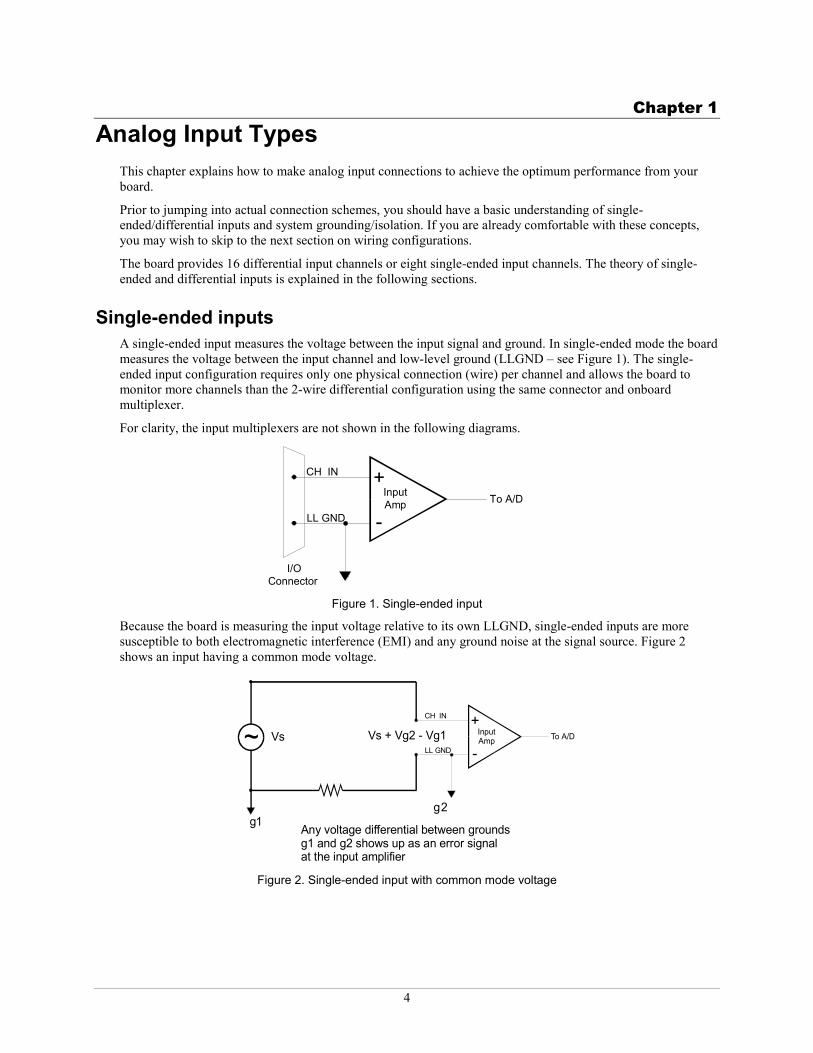
Single-ended inputs A single-ended input measures the voltage between the input signal and ground. In single-ended mode the board measures the voltage between the input channel and low-level ground (LLGND – see Figure 1). The single-ended input configuration requires only one physical connection (wire) per channel and allows the board to monitor more channels than the 2-wire differential configuration using the same connector and onboard multiplexer.
For clarity, the input multiplexers are not shown in the following diagrams.
+
-InputAmp To A/D
I/OConnector
LL GND
CH IN
Figure 1. Single-ended input
Because the board is measuring the input voltage relative to its own LLGND, single-ended inputs are more susceptible to both electromagnetic interference (EMI) and any ground noise at the signal source. Figure 2 shows an input having a common mode voltage.
Figure 2. Single-ended input with common mode voltage
+
-InputAmp To A/D
LL GND
CH IN
~
12
Vs Vs + Vg2 - Vg1
Any voltage differential between groundsg1 and g2 shows up as an error signalat the input amplifier
gg
Guide to Signal Connections Analog Input Types
5
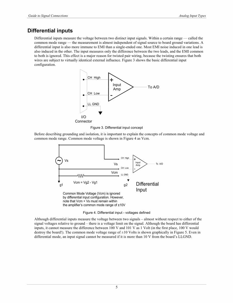
Differential inputs Differential inputs measure the voltage between two distinct input signals. Within a certain range — called the common mode range — the measurement is almost independent of signal source to board ground variations. A differential input is also more immune to EMI than a single-ended one. Most EMI noise induced in one lead is also induced in the other. The input measures only the difference between the two leads, and the EMI common to both is ignored. This effect is a major reason for twisted pair wiring, because the twisting ensures that both wires are subject to virtually identical external influence. Figure 3 shows the basic differential input configuration.
+
-InputAmp To A/D
I/OConnector
LL GND
CH High
CH Low
Figure 3. Differential input concept
Before describing grounding and isolation, it is important to explain the concepts of common mode voltage and common mode range. Common mode voltage is shown in Figure 4 as Vcm.
Figure 4. Differential input - voltages defined
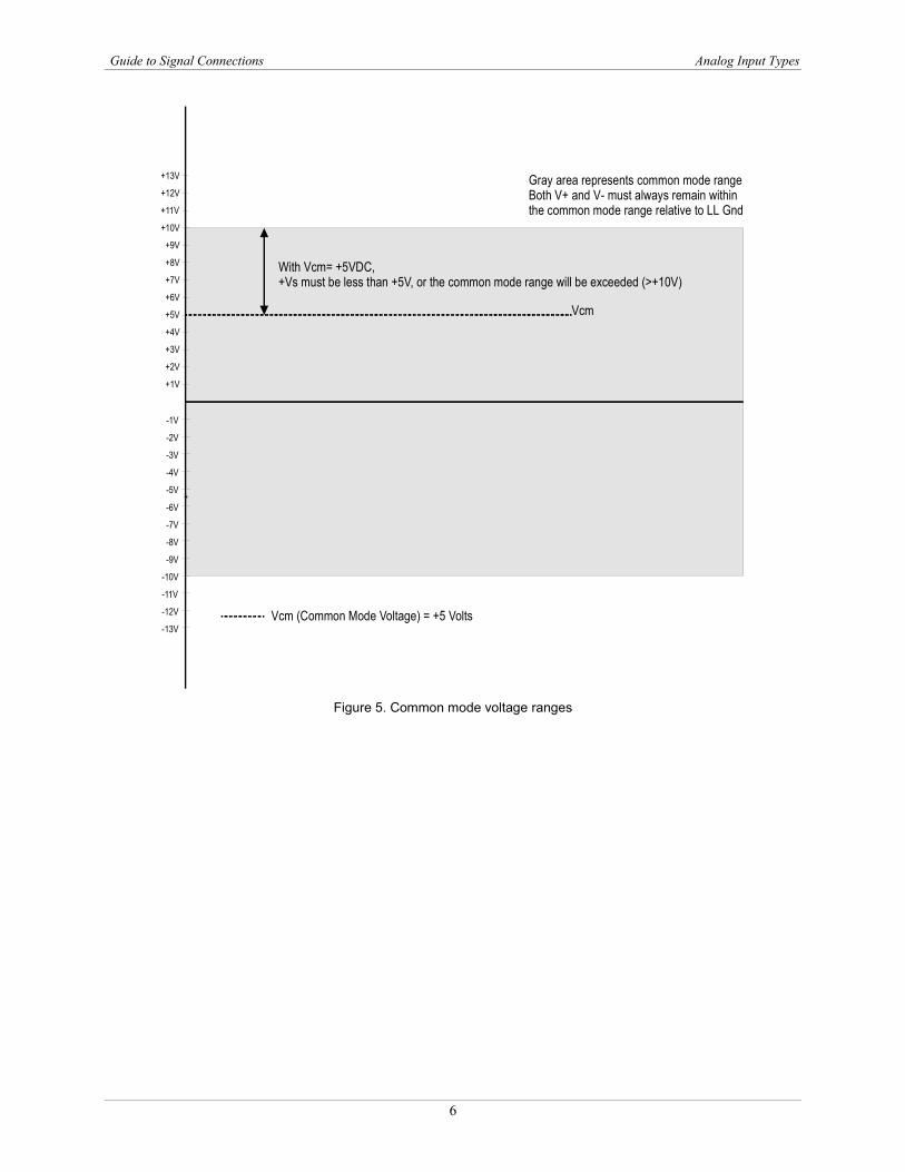
Although differential inputs measure the voltage between two signals – almost without respect to either of the signal voltages relative to ground – there is a voltage limit on the signal. Although the board has differential inputs, it cannot measure the difference between 100 V and 101 V as 1 Volt (in the first place, 100 V would destroy the board!). The common mode voltage range of ±10 Volts is shown graphically in Figure 5. Even in differential mode, an input signal cannot be measured if it is more than 10 V from the board’s LLGND.
+
-InputAmp To A/D
DifferentialInput
LL GND
CH High
CH Low
~ VsVs
Vcm
Common Mode Voltage (Vcm) is ignoredby differential input configuration. However,note that Vcm + Vs must remain withinthe amplifier’s common mode range of ±10V
Vcm = Vg2 - Vg1gg1 2
Guide to Signal Connections Analog Input Types
6
+1V
-13V
+2V
-12V
+3V
-11V
+4V
-10V
+5V
-9V
+6V
-8V
+7V
-7V
+8V
-6V
+9V
-5V
+10V
-4V
+11V
-3V
+12V
-2V
+13V
-1V
Gray area represents common mode rangeBoth V+ and V- must always remain withinthe common mode range relative to LL Gnd
Vcm (Common Mode Voltage) = +5 Volts
Vcm
With Vcm= +5VDC,+Vs must be less than +5V, or the common mode range will be exceeded (>+10V)
Figure 5. Common mode voltage ranges
7
Chapter 2
System Grounds and Isolation There are three ways to connect a signal source to the board:
The board’s input and the signal source may have the same (or common) ground. This signal source can beconnected directly to the board.
The board input and the signal source may have an offset voltage between their grounds (AC and/or DC).This offset is the common mode voltage. Depending on the magnitude of this voltage, you may be able toconnect the board directly to your signal source. We will explain this later.
The board and the signal source may already have isolated grounds. You can connect this signal sourcedirectly to the board.
Ground type determination If possible, use a battery-powered voltmeter to measure the AC and DC voltages between the signal source ground and PC ground. If you do not have access to a battery-powered voltmeter, skip this test and read sections "Systems with common grounds" through "Small common mode voltages." You still may be able to identify your system type from the descriptions provided.
If both AC and DC readings are 0.000 V, you may have a system with common grounds. However, since voltmeters will average out high frequency signals, there is no guarantee. Refer to the section Systems with common grounds on page 8.
If you measure reasonably-stable AC and DC voltages, this offset is the common mode voltage. Refer to the section Systems with common mode (ground offset) voltages on page 8.
Read the following caution carefully, and then proceed to the remaining sections in this chapter describing common mode systems.
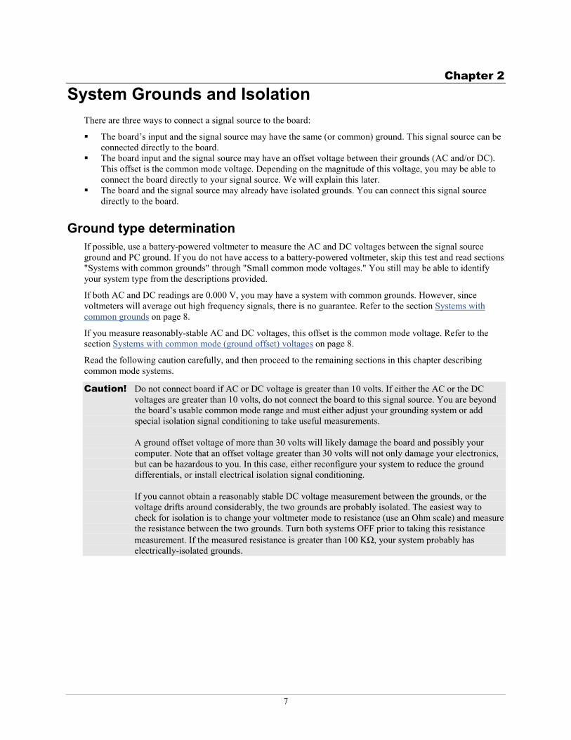
Caution! Do not connect board if AC or DC voltage is greater than 10 volts. If either the AC or the DC voltages are greater than 10 volts, do not connect the board to this signal source. You are beyond the board’s usable common mode range and must either adjust your grounding system or add special isolation signal conditioning to take useful measurements.
A ground offset voltage of more than 30 volts will likely damage the board and possibly your computer. Note that an offset voltage greater than 30 volts will not only damage your electronics, but can be hazardous to you. In this case, either reconfigure your system to reduce the ground differentials, or install electrical isolation signal conditioning.
If you cannot obtain a reasonably stable DC voltage measurement between the grounds, or the voltage drifts around considerably, the two grounds are probably isolated. The easiest way to check for isolation is to change your voltmeter mode to resistance (use an Ohm scale) and measure the resistance between the two grounds. Turn both systems OFF prior to taking this resistance measurement. If the measured resistance is greater than 100 KΩ, your system probably has electrically-isolated grounds.
Guide to Signal Connections System Grounds and Isolation
8
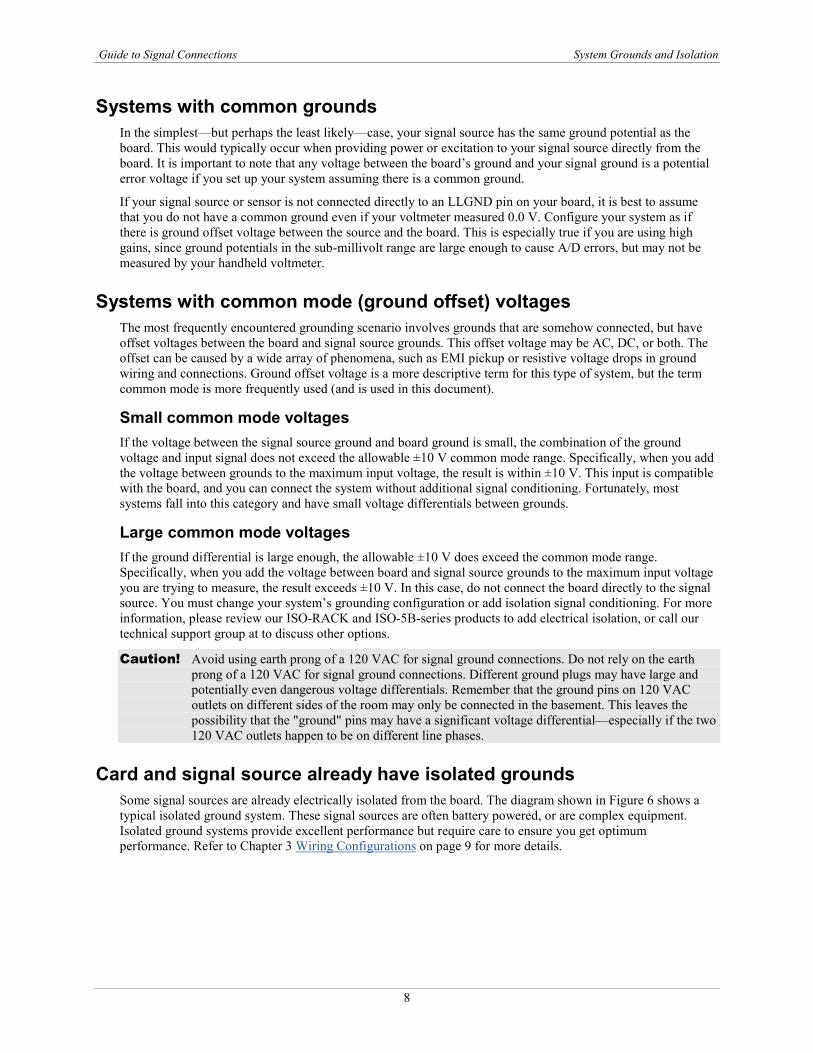
Systems with common grounds In the simplest—but perhaps the least likely—case, your signal source has the same ground potential as the board. This would typically occur when providing power or excitation to your signal source directly from the board. It is important to note that any voltage between the board’s ground and your signal ground is a potential error voltage if you set up your system assuming there is a common ground.
If your signal source or sensor is not connected directly to an LLGND pin on your board, it is best to assume that you do not have a common ground even if your voltmeter measured 0.0 V. Configure your system as if there is ground offset voltage between the source and the board. This is especially true if you are using high gains, since ground potentials in the sub-millivolt range are large enough to cause A/D errors, but may not be measured by your handheld voltmeter.
Systems with common mode (ground offset) voltages The most frequently encountered grounding scenario involves grounds that are somehow connected, but have offset voltages between the board and signal source grounds. This offset voltage may be AC, DC, or both. The offset can be caused by a wide array of phenomena, such as EMI pickup or resistive voltage drops in ground wiring and connections. Ground offset voltage is a more descriptive term for this type of system, but the term common mode is more frequently used (and is used in this document).
Small common mode voltages If the voltage between the signal source ground and board ground is small, the combination of the ground voltage and input signal does not exceed the allowable ±10 V common mode range. Specifically, when you add the voltage between grounds to the maximum input voltage, the result is within ±10 V. This input is compatible with the board, and you can connect the system without additional signal conditioning. Fortunately, most systems fall into this category and have small voltage differentials between grounds.
Large common mode voltages If the ground differential is large enough, the allowable ±10 V does exceed the common mode range. Specifically, when you add the voltage between board and signal source grounds to the maximum input voltage you are trying to measure, the result exceeds ±10 V. In this case, do not connect the board directly to the signal source. You must change your system’s grounding configuration or add isolation signal conditioning. For more information, please review our ISO-RACK and ISO-5B-series products to add electrical isolation, or call our technical support group at to discuss other options.
Caution! Avoid using earth prong of a 120 VAC for signal ground connections. Do not rely on the earth prong of a 120 VAC for signal ground connections. Different ground plugs may have large and potentially even dangerous voltage differentials. Remember that the ground pins on 120 VAC outlets on different sides of the room may only be connected in the basement. This leaves the possibility that the "ground" pins may have a significant voltage differential—especially if the two 120 VAC outlets happen to be on different line phases.
Card and signal source already have isolated grounds Some signal sources are already electrically isolated from the board. The diagram shown in Figure 6 shows a typical isolated ground system. These signal sources are often battery powered, or are complex equipment. Isolated ground systems provide excellent performance but require care to ensure you get optimum performance. Refer to Chapter 3 Wiring Configurations on page 9 for more details.
9
Chapter 3
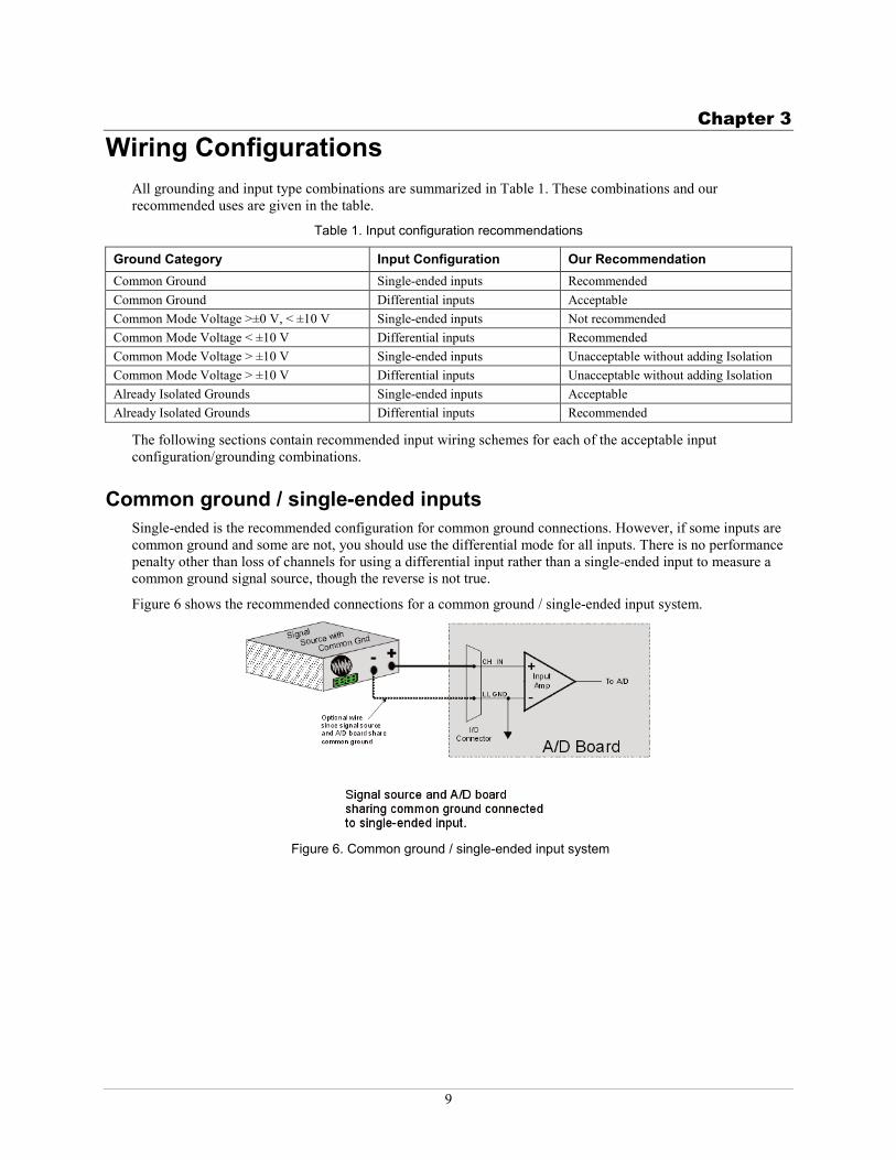
Wiring Configurations All grounding and input type combinations are summarized in Table 1. These combinations and our recommended uses are given in the table.
Table 1. Input configuration recommendations
Ground Category Input Configuration Our Recommendation Common Ground Single-ended inputs Recommended Common Ground Differential inputs Acceptable Common Mode Voltage >±0 V, < ±10 V Single-ended inputs Not recommended Common Mode Voltage < ±10 V Differential inputs Recommended Common Mode Voltage > ±10 V Single-ended inputs Unacceptable without adding Isolation Common Mode Voltage > ±10 V Differential inputs Unacceptable without adding Isolation Already Isolated Grounds Single-ended inputs Acceptable Already Isolated Grounds Differential inputs Recommended
The following sections contain recommended input wiring schemes for each of the acceptable input configuration/grounding combinations.
Common ground / single-ended inputs Single-ended is the recommended configuration for common ground connections. However, if some inputs are common ground and some are not, you should use the differential mode for all inputs. There is no performance penalty other than loss of channels for using a differential input rather than a single-ended input to measure a common ground signal source, though the reverse is not true.
Figure 6 shows the recommended connections for a common ground / single-ended input system.
Figure 6. Common ground / single-ended input system
Guide to Signal Connections Wiring Configurations
10
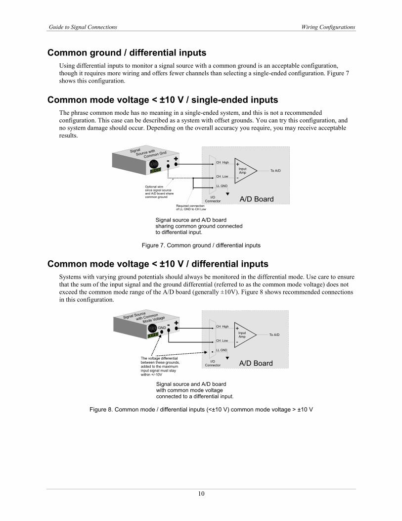
Common ground / differential inputs Using differential inputs to monitor a signal source with a common ground is an acceptable configuration, though it requires more wiring and offers fewer channels than selecting a single-ended configuration. Figure 7 shows this configuration.
Common mode voltage < ±10 V / single-ended inputs The phrase common mode has no meaning in a single-ended system, and this is not a recommended configuration. This case can be described as a system with offset grounds. You can try this configuration, and no system damage should occur. Depending on the overall accuracy you require, you may receive acceptable results.
Figure 7. Common ground / differential inputs
Common mode voltage < ±10 V / differential inputs Systems with varying ground potentials should always be monitored in the differential mode. Use care to ensure that the sum of the input signal and the ground differential (referred to as the common mode voltage) does not exceed the common mode range of the A/D board (generally ±10V). Figure 8 shows recommended connections in this configuration.
Figure 8. Common mode / differential inputs (<±10 V) common mode voltage > ±10 V
+
-InputAmp To A/D
A/D BoardI/OConnector
LL GND
CH High
CH Low
+- Signal
Source with
Common Gnd
Optional wiresince signal sourceand A/D board sharecommon ground
Required connectionof LL GND to CH Low
Signal source and A/D board sharing common ground connectedto differential input.
+
-InputAmp To A/D
A/D BoardI/OConnector
LL GND
CH High
CH Low
+-Signal Source
with Common
Mode Voltage
Signal source and A/D board with common mode voltageconnected to a differential input.
GND
The voltage differentialbetween these grounds,added to the maximum input signal must stay within +/-10V
Guide to Signal Connections Wiring Configurations
11
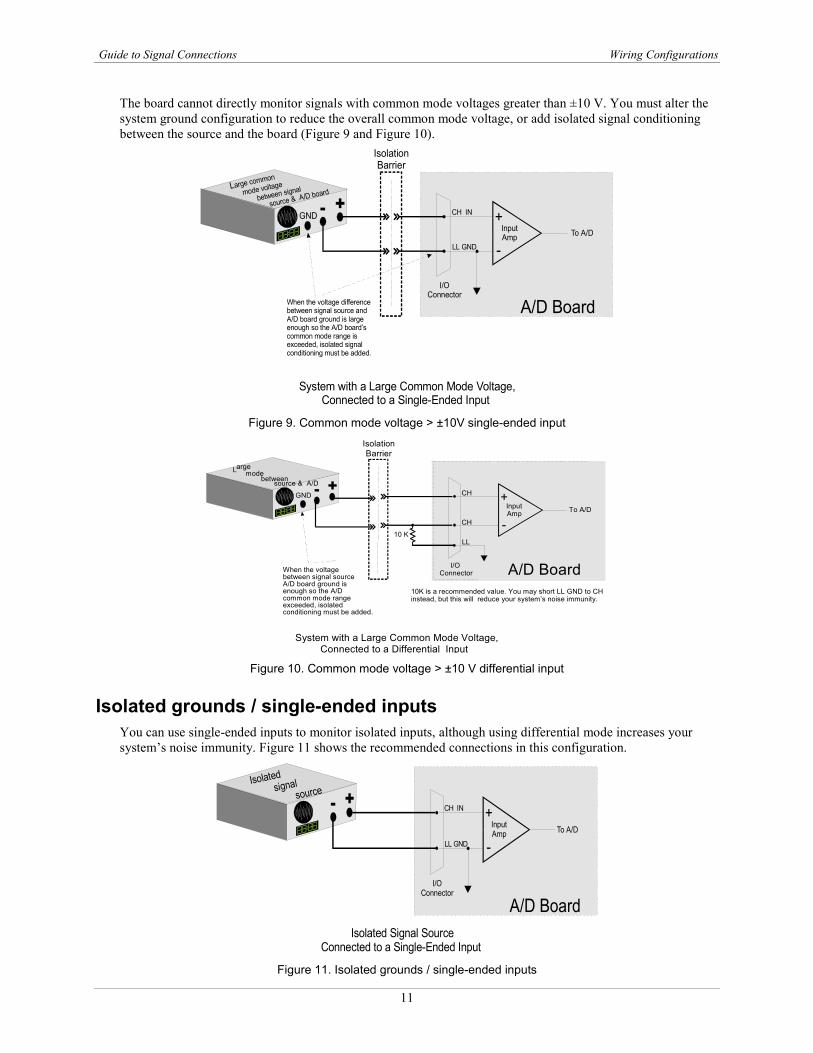
The board cannot directly monitor signals with common mode voltages greater than ±10 V. You must alter the system ground configuration to reduce the overall common mode voltage, or add isolated signal conditioning between the source and the board (Figure 9 and Figure 10).
Figure 9. Common mode voltage > ±10V single-ended input
Figure 10. Common mode voltage > ±10 V differential input
Isolated grounds / single-ended inputs You can use single-ended inputs to monitor isolated inputs, although using differential mode increases your system’s noise immunity. Figure 11 shows the recommended connections in this configuration.
Figure 11. Isolated grounds / single-ended inputs
System with a Large Common Mode Voltage,Connected to a Single-Ended Input
I/OConnector
+
-InputAmp To A/D
LL GND
CH IN
A/D Board
+-Large common
mode voltage
between signal
source & A/D board
GND
IsolationBarrier
When the voltage differencebetween signal source andA/D board ground is largeenough so the A/D board’scommon mode range isexceeded, isolated signalconditioning must be added.
System with a Large Common Mode Voltage, Connected to a Differential Input
+ - L arge mode
between source & A/D GND
Isolation Barrier
When the voltage between signal source A/D board ground is enough so the A/D common mode range exceeded, isolated conditioning must be added.
+
- Input Amp To A/D
A/D Board I/O Connector
LL
CH CH 10 K
10K is a recommended value. You may short LL GND to CH instead, but this will reduce your system’s noise immunity.
Isolated Signal SourceConnected to a Single-Ended Input
I/OConnector
+
-InputAmp To A/D
LL GND
CH IN
A/D Board
+-Isolated signal
source
Guide to Signal Connections Wiring Configurations
12
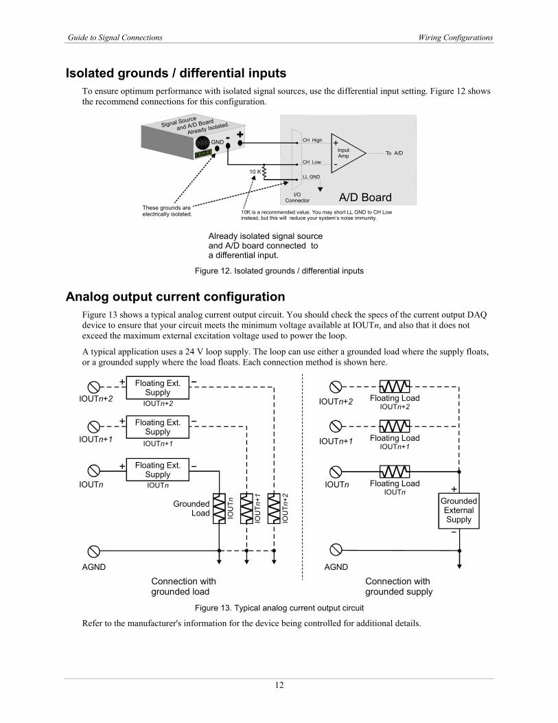
Isolated grounds / differential inputs To ensure optimum performance with isolated signal sources, use the differential input setting. Figure 12 shows the recommend connections for this configuration.
Figure 12. Isolated grounds / differential inputs
Analog output current configuration Figure 13 shows a typical analog current output circuit. You should check the specs of the current output DAQ device to ensure that your circuit meets the minimum voltage available at IOUTn, and also that it does not exceed the maximum external excitation voltage used to power the loop.
A typical application uses a 24 V loop supply. The loop can use either a grounded load where the supply floats, or a grounded supply where the load floats. Each connection method is shown here.
Figure 13. Typical analog current output circuit
Refer to the manufacturer's information for the device being controlled for additional details.
+
-InputAmp To A/D
A/D BoardI/OConnector
LL GND
CH High
CH Low
+-Signal Source
and A/D Board
Already Isolated.
Already isolated signal source and A/D board connected to a differential input.
GND
These grounds areelectrically isolated.
10 K
10K is a recommended value. You may short LL GND to CH Lowinstead, but this will reduce your system’s noise immunity.
Connection with grounded load
Connection with grounded supply
GroundedExternalSupply
+IOUTn
AGND
Floating LoadIOUTn
IOUTn+1
IOUTn+2
Floating LoadIOUTn+1
Floating LoadIOUTn+2
IOUTn
AGND
GroundedLoad
IOUTn+1
IOUTn+2
+ Floating SupplyIOUTn+1
Floating Ext.Supply
+ Floating SupplyIOUTn+1
Floating Ext.Supply
+ Floating SupplyIOUTn+1
Floating Ext.Supply
IOU
Tn+2
IOU
Tn
IOU
Tn+1
IOUTn+1
IOUTn+2
IOUTn
13
Chapter 4
Digital I/O Techniques This short introduction describes a few topics often needed by board users. It covers a few key application techniques used with digital I/O.
When the board is powered-on or reset, digital I/O pins are set to high impedance input Whenever the board is powered-on or reset, all digital I/O pins are set to high impedance. If you have output devices such as solid state relays, they may be switched on whenever the computer is powered on or reset. To prevent unwanted switching, and to drive all outputs to a known, safe state after power-on or reset, pull all pins either high or low through a suitable resistor.
Whenever the board is powered on or reset, the digital I/O control registers are set to a known state. If pull-up/pull-down resistors are not used, the input bits typically, but not certainly, float high when in the input mode. There may also be enough drive current available from the inputs to turn on connected devices.
If you leave the inputs of the device you are controlling to float, they may float up or down. The way they float depends on the characteristics of the circuit and the electrical environment, and may be unpredictable. The result is that your controlled device may turn on. This is why pull-up or pull-down resistors are needed.
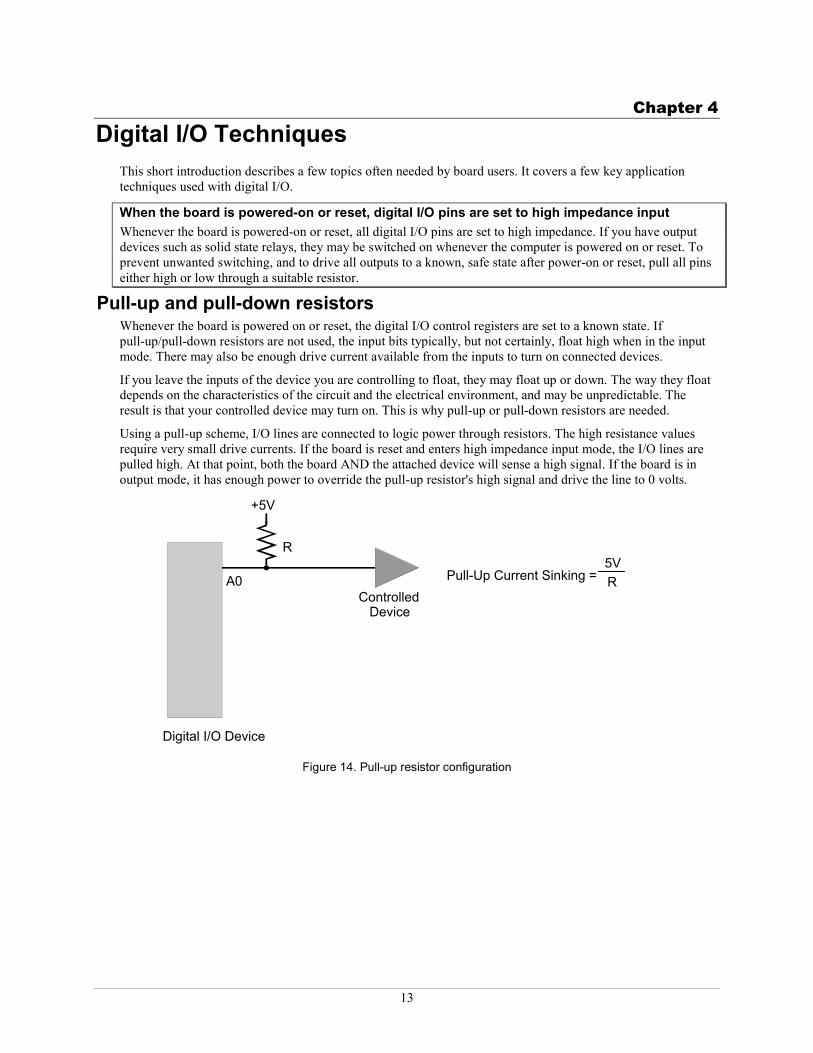
Using a pull-up scheme, I/O lines are connected to logic power through resistors. The high resistance values require very small drive currents. If the board is reset and enters high impedance input mode, the I/O lines are pulled high. At that point, both the board AND the attached device will sense a high signal. If the board is in output mode, it has enough power to override the pull-up resistor's high signal and drive the line to 0 volts.
Digital I/O Device
+5V
R
Controlled Device
A0 Pull-Up Current Sinking = 5V R
Figure 14. Pull-up resistor configuration
Pull-up and pull-down resistors
Guide to Signal Connections Digital I/O Techniques
14
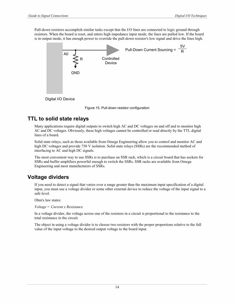
Pull-down resistors accomplish similar tasks except that the I/O lines are connected to logic ground through resistors. When the board is reset, and enters high impedance input mode, the lines are pulled low. If the board is in output mode, it has enough power to override the pull-down resistor's low signal and drive the lines high.
R Controlled Device
A0
Digital I/O Device
Pull-Down Current Sourcing = 5V R
GND
Figure 15. Pull-down resistor configuration
TTL to solid state relays Many applications require digital outputs to switch high AC and DC voltages on and off and to monitor high AC and DC voltages. Obviously, these high voltages cannot be controlled or read directly by the TTL digital lines of a board.
Solid state relays, such as those available from Omega Engineering allow you to control and monitor AC and high DC voltages and provide 750 V isolation. Solid state relays (SSRs) are the recommended method of interfacing to AC and high DC signals.
The most convenient way to use SSRs is to purchase an SSR rack, which is a circuit board that has sockets for SSRs and buffer amplifiers powerful enough to switch the SSRs. SSR racks are available from Omega Engineering and most manufacturers of SSRs.
Voltage dividers If you need to detect a signal that varies over a range greater than the maximum input specification of a digital input, you must use a voltage divider or some other external device to reduce the voltage of the input signal to a safe level.
Ohm's law states:
Voltage = Current x Resistance
In a voltage divider, the voltage across one of the resistors in a circuit is proportional to the resistance to the total resistance in the circuit.
The object in using a voltage divider is to choose two resistors with the proper proportions relative to the full value of the input voltage to the desired output voltage to the board input.
Guide to Signal Connections Digital I/O Techniques
15
Signal High
Signal Volts
Signal Low
Vin
R1
R2
V1
V2Vout
BoardInput
Groundt
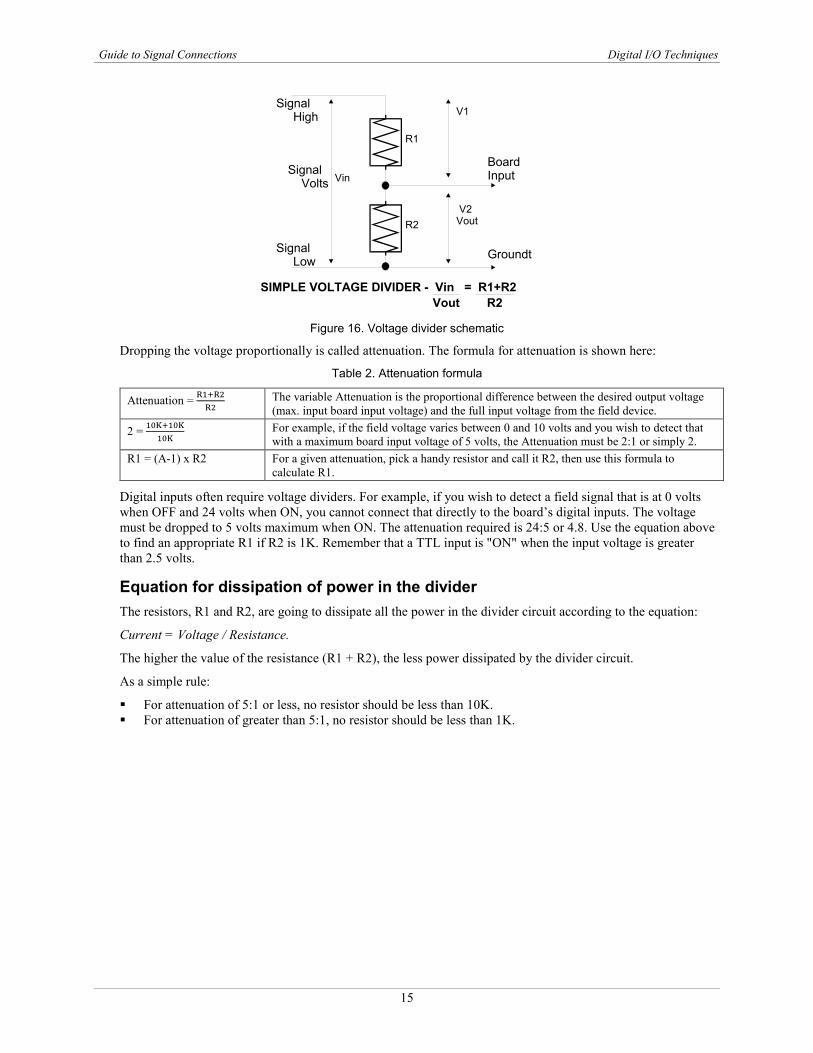
SIMPLE VOLTAGE DIVIDER - Vin = R1+R2Vout R2
Figure 16. Voltage divider schematic
Dropping the voltage proportionally is called attenuation. The formula for attenuation is shown here:
Table 2. Attenuation formula
Attenuation = R1+R2R2
The variable Attenuation is the proportional difference between the desired output voltage (max. input board input voltage) and the full input voltage from the field device.
2 = 10K+10K10K
For example, if the field voltage varies between 0 and 10 volts and you wish to detect that with a maximum board input voltage of 5 volts, the Attenuation must be 2:1 or simply 2.
R1 = (A-1) x R2 For a given attenuation, pick a handy resistor and call it R2, then use this formula to calculate R1.
Digital inputs often require voltage dividers. For example, if you wish to detect a field signal that is at 0 volts when OFF and 24 volts when ON, you cannot connect that directly to the board’s digital inputs. The voltage must be dropped to 5 volts maximum when ON. The attenuation required is 24:5 or 4.8. Use the equation above to find an appropriate R1 if R2 is 1K. Remember that a TTL input is "ON" when the input voltage is greater than 2.5 volts.
Equation for dissipation of power in the divider The resistors, R1 and R2, are going to dissipate all the power in the divider circuit according to the equation:
Current = Voltage / Resistance.
The higher the value of the resistance (R1 + R2), the less power dissipated by the divider circuit.
As a simple rule:
For attenuation of 5:1 or less, no resistor should be less than 10K. For attenuation of greater than 5:1, no resistor should be less than 1K.
Guide to Signal Connections Digital I/O Techniques
16
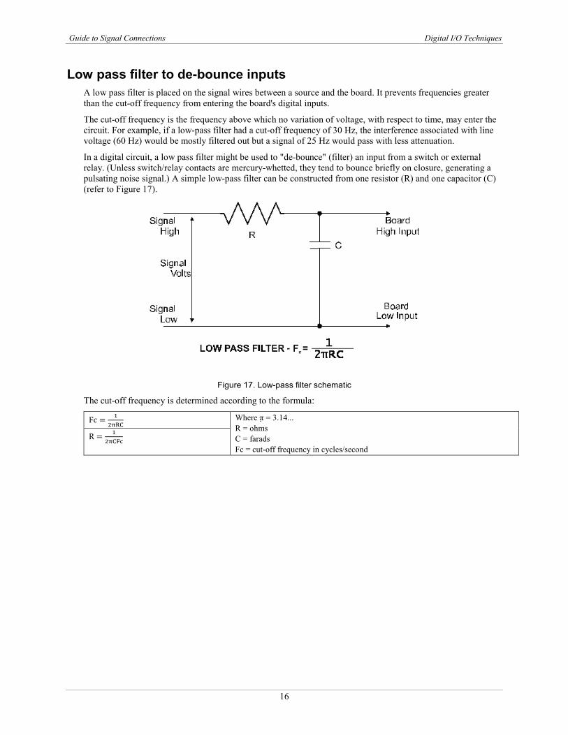
Low pass filter to de-bounce inputs A low pass filter is placed on the signal wires between a source and the board. It prevents frequencies greater than the cut-off frequency from entering the board's digital inputs.
The cut-off frequency is the frequency above which no variation of voltage, with respect to time, may enter the circuit. For example, if a low-pass filter had a cut-off frequency of 30 Hz, the interference associated with line voltage (60 Hz) would be mostly filtered out but a signal of 25 Hz would pass with less attenuation.
In a digital circuit, a low pass filter might be used to "de-bounce" (filter) an input from a switch or external relay. (Unless switch/relay contacts are mercury-whetted, they tend to bounce briefly on closure, generating a pulsating noise signal.) A simple low-pass filter can be constructed from one resistor (R) and one capacitor (C) (refer to Figure 17).
Figure 17. Low-pass filter schematic
The cut-off frequency is determined according to the formula:
Fc = 12πRC
Where π = 3.14... R = ohms C = farads Fc = cut-off frequency in cycles/second
R = 12πCFc
OMEGA’s policy is to make running changes, not model changes, whenever an improvement is possible. This affords our customers the latest in technology and engineering.OMEGA is a registered trademark of OMEGA ENGINEERING, INC.© Copyright 2016 OMEGA ENGINEERING, INC. All rights reserved. This document may not be copied, photocopied, reproduced, translated, or reduced to any electronic medium or machine-readable form, in whole or in part, without the prior written consent of OMEGA ENGINEERING, INC.
FOR WARRANTY RETURNS, please have the following information available BEFORE contacting OMEGA:1. Purchase Order number under which the product
was PURCHASED,2. Model and serial number of the product under
warranty, and3. Repair instructions and/or specific problems relative to the product.
FOR NON-WARRANTY REPAIRS, consult OMEGA for current repair charges. Have the following information available BEFORE contacting OMEGA:1. Purchase Order number to cover the COST of the repair,2. Model and serial number of the product, and3. Repair instructions and/or specific problems relative to the product.
RETURN REQUESTS/INQUIRIESDirect all warranty and repair requests/inquiries to the OMEGA Customer Service Department. BEFORE RETURNING ANY PRODUCT(S) TO OMEGA, PURCHASER MUST OBTAIN AN AUTHORIZED RETURN (AR) NUMBER FROM OMEGA’S CUSTOMER SERVICE DEPARTMENT (IN ORDER TO AVOID PROCESSING DELAYS). The assigned AR number should then be marked on the outside of the return package and on any correspondence.The purchaser is responsible for shipping charges, freight, insurance and proper packaging to prevent breakage in transit.
WARRANTY/DISCLAIMEROMEGA ENGINEERING, INC. warrants this unit to be free of defects in materials and workmanship for a period of 13 months from date of purchase. OMEGA’s WARRANTY adds an additional one (1) month grace period to the normal one (1) year product warranty to cover handling and shipping time. This ensures that OMEGA’s customers receive maximum coverage on each product.If the unit malfunctions, it must be returned to the factory for evaluation. OMEGA’s Customer Service Department will issue an Authorized Return (AR) number immediately upon phone or written request. Upon examination by OMEGA, if the unit is found to be defective, it will be repaired or replaced at no charge. OMEGA’s WARRANTY does not apply to defects resulting from any action of the purchaser, including but not limited to mishandling, improper interfacing, operation outside of design limits, improper repair, or unauthorized modification. This WARRANTY is VOID if the unit shows evidence of having been tampered with or shows evidence of having been damaged as a result of excessive corrosion; or current, heat, moisture or vibration; improper specification; misapplication; misuse or other operating conditions outside of OMEGA’s control. Components in which wear is not warranted, include but are not limited to contact points, fuses, and triacs.OMEGA is pleased to offer suggestions on the use of its various products. However, OMEGA neither assumes responsibility for any omissions or errors nor assumes liability for any damages that result from the use of its products in accordance with information provided by OMEGA, either verbal or written. OMEGA warrants only that the parts manufactured by the company will be as specified and free of defects. OMEGA MAKES NO OTHER WARRANTIES OR REPRESENTATIONS OF ANY KIND WHATSOEVER, EXPRESSED OR IMPLIED, EXCEPT THAT OF TITLE, AND ALL IMPLIED WARRANTIES INCLUDING ANY WARRANTY OF MERCHANTABILITY AND FITNESS FOR A PARTICULAR PURPOSE ARE HEREBY DISCLAIMED. LIMITATION OF LIABILITY: The remedies of purchaser set forth herein are exclusive, and the total liability of OMEGA with respect to this order, whether based on contract, warranty, negligence, indemnification, strict liability or otherwise, shall not exceed the purchase price of the component upon which liability is based. In no event shall OMEGA be liable for consequential, incidental or special damages.CONDITIONS: Equipment sold by OMEGA is not intended to be used, nor shall it be used: (1) as a “Basic Component” under 10 CFR 21 (NRC), used in or with any nuclear installation or activity; or (2) in medical applications or used on humans. Should any Product(s) be used in or with any nuclear installation or activity, medical application, used on humans, or misused in any way, OMEGA assumes no responsibility as set forth in our basic WARRANTY/DISCLAIMER language, and, additionally, purchaser will indemnify OMEGA and hold OMEGA harmless from any liability or damage whatsoever arising out of the use of the Product(s) in such a manner.
M4830/0216
Where Do I Find Everything I Need for Process Measurement and Control?
OMEGA…Of Course!Shop online at omega.com SM
TEMPERATUREMU Thermocouple, RTD & Thermistor Probes, Connectors, Panels & Assemblies MU Wire: Thermocouple, RTD & ThermistorMU Calibrators & Ice Point ReferencesMU Recorders, Controllers & Process MonitorsMU Infrared Pyrometers
PRESSURE, STRAIN AND FORCEMU Transducers & Strain GagesMU Load Cells & Pressure GagesMU Displacement TransducersMU Instrumentation & Accessories
FLOW/LEVELMU Rotameters, Gas Mass Flowmeters & Flow ComputersMU Air Velocity IndicatorsMU Turbine/Paddlewheel SystemsMU Totalizers & Batch Controllers
pH/CONDUCTIVITYMU pH Electrodes, Testers & AccessoriesMU Benchtop/Laboratory MetersMU Controllers, Calibrators, Simulators & PumpsMU Industrial pH & Conductivity Equipment
DATA ACQUISITIONMU Data Acquisition & Engineering SoftwareMU Communications-Based Acquisition SystemsMU Plug-in Cards for Apple, IBM & CompatiblesMU Data Logging SystemsMU Recorders, Printers & Plotters
HEATERSMU Heating CableMU Cartridge & Strip HeatersMU Immersion & Band HeatersMU Flexible HeatersMU Laboratory Heaters
ENVIRONMENTAL MONITORING AND CONTROLMU Metering & Control InstrumentationMU RefractometersMU Pumps & TubingMU Air, Soil & Water MonitorsMU Industrial Water & Wastewater TreatmentMU pH, Conductivity & Dissolved Oxygen Instruments