short range radar reference design using awr1642 … · • single-chip fmcw radio detection and...
TRANSCRIPT

PC GUI AWR1642 EVM
UART port-1
UART port-2 TX a
R
Copyright © 2017, Texas Instrument
1TIDUD36B–April 2017–Revised January 2018Submit Documentation Feedback
Copyright © 2017–2018, Texas Instruments Incorporated
Short Range Radar Reference Design Using AWR1642
TI Designs: TIDEP-0092Short Range Radar Reference Design Using AWR1642
DescriptionThe TIDEP-0092 provides a foundation for a shortrange radar (SRR) application using the AWR1642evaluation module (EVM). This design allows the userto estimate and track the position (in the azimuthalplane) and the velocity of objects in its field of view upto 80 m.
Resources
TIDEP-0092 Design FolderAWR1642 Product FolderTCAN1042 Product FolderTMP112 Product FolderLP87524 Tool Folder
ASK Our E2E Experts
Features• Single-Chip FMCW Radio Detection and Ranging
(RADAR) for SRR Applications• Detect Objects (Such as Cars and Trucks) up to
80-m Away With Range Resolution of 35 cm;Objects 20-m Away Detectable With Resolution of4.3 cm
• Clustering and Tracking on Detected Outputs• Antenna Field of View ±60º With Angular
Resolution of Approximately 15º• Source Code for Fast Fourier Transform (FFT)
Processing and Detection Provided by mmWaveSoftware Development Kit (SDK)
• AWR1642 Demonstrates Design• Radar Front End and Detection Configuration Fully
Explained
Applications• Lane Change Assist (LCA)• Autonomous Parking• Cross Traffic Alert (CTA)• Blind Spot Detection (BSD)
An IMPORTANT NOTICE at the end of this TI reference design addresses authorized use, intellectual property matters and otherimportant disclaimers and information.
System Description www.ti.com
2 TIDUD36B–April 2017–Revised January 2018Submit Documentation Feedback
Copyright © 2017–2018, Texas Instruments Incorporated
Short Range Radar Reference Design Using AWR1642
1 System DescriptionAutonomous control of a vehicle provides quality-of-life and safety benefits in addition to making therelatively mundane act of driving safer and less difficult. The quality-of-life features include the ability of avehicle to park itself or to determine whether a lane change is possible and provide features like automaticcruise control—where a vehicle maintains a constant distance with respect to the car ahead of it,essentially tracking the velocity of the car in front of it. Autonomous breaking and collision avoidance aresafety features that prevent accidents caused by driver inattention. These features work by observing thearea in front of a car and alerting the autonomous driving subsystems if obstacles are observed that arelikely to hit the car. Implementing these technologies require a variety of sensors to detect obstacles in theenvironment and track their velocities and positions over time.
1.1 Why Radar?Frequency-modulated continuous-wave (FMCW) radars allow the accurate measurement of distances andrelative velocities of obstacles and other vehicles; therefore, radars are useful for autonomous vehicularapplications (such as parking assist and lane change assist) and car safety applications (autonomousbreaking and collision avoidance). An important advantage of radars over camera and light-detection-and-ranging (LIDAR)-based systems is that radars are relatively immune to environmental conditions (such asthe effects of rain, dust, and smoke). Because FMCW radars transmit a specific signal (called a chirp) andprocess the reflections, they can work in complete darkness and also bright daylight (radars are notaffected by glare). When compared with ultrasound, radars typically have a much longer range and muchfaster time of transit for their signals.
1.2 TI SRR DesignThe TIDEP-0092 is an introductory application that is configured for short range applications (that is todetect as many as 200 objects up to a distance of 80 m (260 feet) and track as many as 24 of themtravelling as fast as 90 kph, which is approximately 55 mph). In the short range application, the AWR1642sensor is configured as a multi-mode radar, which means that it can simultaneously track objects at 80 mwhile generating a rich point cloud of objects at 20 m, so that approaching vehicles and closer smallobjects can be detected at the same time. This reference design can be used as a starting point to designa standalone sensor for a variety of SRR automotive applications. A range of more than 80 m can beachieved with the design of an antenna with higher gain than the one included in the AWR1642.
1.3 Key System SpecificationsThis reference design has two sets of specifications because the radar is used as a multi-mode radar. Thefirst specification is for the short range radar (SRR), which has a range of 80 m. The second specificationis for the ultra-short-range radar (USRR), which has an effective range of only 20 m.
Table 1. Key System Specifications
PARAMETER SPECIFICATIONS DETAILS
Maximum range 80 m (SRR), 2 0m (USRR) This represents the maximum distance that the radar can detect an objectrepresenting an RCS of approximately 10 m2.
Range resolution 36.6 cm (SRR), 4.3 cm (USRR) Range resolution is the ability of a radar system to distinguish betweentwo or more targets on the same bearing but at different ranges.
Maximum velocity 90 kph (SRR), 36 kph (USRR)
This is the native maximum velocity obtained using a two-dimensionalFFT on the frame data. This specification will be improved over time byshowing how higher-level algorithms can extend the maximummeasurable velocity beyond this limit.
Velocity resolution 0.52 m/s (SRR), 0.32 m/s (USRR)This parameter represents the capability of the radar sensor to distinguishbetween two or more objects at the same range but moving with differentvelocities.

PC GUI AWR1642 EVM
UART port-1
UART port-2 TX a
R
Copyright © 2017, Texas Instrument
www.ti.com System Overview
3TIDUD36B–April 2017–Revised January 2018Submit Documentation Feedback
Copyright © 2017–2018, Texas Instruments Incorporated
Short Range Radar Reference Design Using AWR1642
2 System Overview
2.1 Block Diagram
Figure 1. SRR System Block Diagram
2.2 Highlighted Products
2.2.1 AWR1642 Single-Chip Radar SolutionThe AWR1642 is an integrated single-chip, frequency modulated continuous wave (FMCW) sensorcapable of operation in the 76 to 81 GHz frequency band. The device is built with TI’s low-power, 45-nmRFCMOS processor and enables unprecedented levels of analog and digital integration in an extremelysmall form factor. The device has four receivers and two transmitters with a closed-loop phase-locked loop(PLL) for precise and linear chirp synthesis. The sensor includes a built-in radio processor (BIST) for RFcalibration and safety monitoring. Based on complex baseband architecture, the sensor device supportsan IF bandwidth of 5 MHz with reconfigurable output sampling rates. The presence of ARM® Cortex® R4Fand Texas Instruments C674x Digital Signal Processor (DSP) (fixed and floating point) along with 1.5MBof on-chip RAM enables high-level algorithm development.

PMIC
LDO1
LDO2AWR1642
2.3 V
1.8 V
1.2 V
3.3 VIO
1.8 V
1.3 VLV
DS
dat
a an
d C
lK
JTA
G a
nd tr
ace
QSPIFlash
EN control from the MCU
PGOOD signal to MCU for power sequencing
Optional for 3.3-Vfrom MCU
/DXQFK3DG�
60-pin HD
XDS110
CANFD
SOP
PC Interface through USB
BP
Con
nect
or
SPI, UART, I2C, Rst, Nerrs, SOPs,
Loggers, CAN, and GPIOs
Control signals for external MCU interface
5-V input from jack and MCU
Current measurement
UART and JTAG
Power and 2 GPIOLED indicators
40 ± MhzXTAL
4RX and 2 TX PCBs
Copyright © 2017, Texas Instruments Incorporated
System Overview www.ti.com
4 TIDUD36B–April 2017–Revised January 2018Submit Documentation Feedback
Copyright © 2017–2018, Texas Instruments Incorporated
Short Range Radar Reference Design Using AWR1642
2.2.2 AWR1642 FeaturesThe AWR1642 has the following features:1. AWR1642 radar device2. Power management circuit to provide all the required supply rails from a single 5-V input3. Two onboard TX antennas and four RX antennas4. Onboard XDS110 that provides a JTAG interface, UART1 for loading the radar configuration on the
AWR1642 device, and UART2 to send the object data back to the PC
Figure 2. AWR1642 Block Diagram
For more details on the hardware, see AWR1642 Evaluation Module (AWR1642BOOST) Single-ChipmmWave Sensing Solution. The schematics and design database can be found in the followingdocuments: AWR1642 Evaluation Board Design Database and AWR1642BOOST Schematic, Assembly,and BOM.
xx
xxxxxxxxxx
Rx1 Rx2 Rx3 Rx4 Rx1 Rx2 Rx3 Rx4
Tx1 Tx2
xxxx
Real Antennas
Virtual Antennas
Tx2Tx1
Fre
quen
cy
Time
Copyright © 2017, Texas Instruments Incorporated
www.ti.com System Overview
5TIDUD36B–April 2017–Revised January 2018Submit Documentation Feedback
Copyright © 2017–2018, Texas Instruments Incorporated
Short Range Radar Reference Design Using AWR1642
2.3 System Design Theory—Chirp Configuration
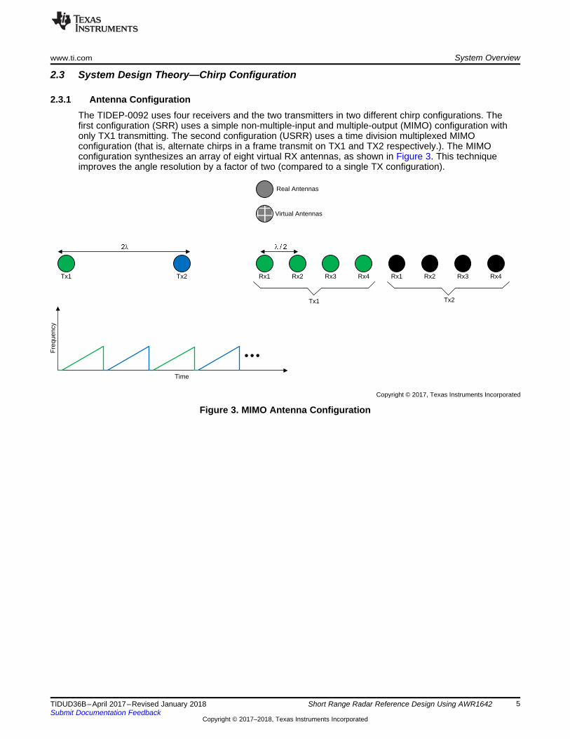
2.3.1 Antenna ConfigurationThe TIDEP-0092 uses four receivers and the two transmitters in two different chirp configurations. Thefirst configuration (SRR) uses a simple non-multiple-input and multiple-output (MIMO) configuration withonly TX1 transmitting. The second configuration (USRR) uses a time division multiplexed MIMOconfiguration (that is, alternate chirps in a frame transmit on TX1 and TX2 respectively.). The MIMOconfiguration synthesizes an array of eight virtual RX antennas, as shown in Figure 3. This techniqueimproves the angle resolution by a factor of two (compared to a single TX configuration).
Figure 3. MIMO Antenna Configuration

System Overview www.ti.com
6 TIDUD36B–April 2017–Revised January 2018Submit Documentation Feedback
Copyright © 2017–2018, Texas Instruments Incorporated
Short Range Radar Reference Design Using AWR1642
2.3.2 Chirp Configuration and System PerformanceTo achieve the specific SRR use case with a visibility range of approximately 80 m and memoryavailability of AWR1642, the chirp configuration in Table 2 is used.
Table 2. Chirp Configuration
PARAMETER SPECIFICATIONSIdle time (µs) 3 (SRR), 7 (USRR)
ADC start time (µs) 3 (SRR), 5 (USRR)Ramp end time (µs) 56 (SRR), 87.3 (USRR)
Number of ADC samples 256 (SRR), 512 (USRR)Frequency slope (MHz/µs) 8 (SRR), 42 (USRR)
ADC sampling frequency (ksps) 5000 (SRR), 6250 (USRR)MIMO (1→yes) 0 (SRR), 1 (USRR)
Number of chirps per profile 128 (SRR), 64 (USRR)Effective chirp time (usec) 51 (SRR), 82 (USRR)
Bandwidth (MHz) 409 (SRR), 3456 (USRR)Frame length (ms) 7.3 (SRR), 6.03 (USRR)
Memory requirements (KB) 512 (SRR and USRR)
(1) Though not implemented in the current SRR design, note that there are several approaches that can improve the maximum detectablevelocity several multiples beyond this native maximum.
The Table 2 configuration is selected to achieve the system performance shown in Table 3. The primarygoal was to achieve a maximum distance of about 80 m. Note that the product of the frequency slope andthe maximum distance is limited by the available IF bandwidth (6.25 MHz for the AWR1642). Thus, amaximum distance of 85 m locks down the frequency slope of the chirp to about 8 MHz/µs. SeeProgramming Chirp Parameters in TI Radar Devices for more details. The choice of the chirp periodicity isa trade-off between range resolution and maximum velocity. This design uses a range-resolution of about0.3 m, which leaves a native maximum velocity of about 55 kph (1) . For details on the connection betweenthe system performance and the chirp parameters, see Programming Chirp Parameters in TI RadarDevices. Through high-level algorithms, the maximum unambiguous velocity that can be detected is90 kph.
A larger maximum distance translates to a lower range resolution (due to limitations on both the L3memory and the IF bandwidth). A useful technique to work around this trade-off is to have multipleconfigurations with each tailored for a specific viewing range. For example, it is typical to have the SRRradar alternate between two modes: a low resolution mode targeting a larger maximum distance (such as85 m with 0.3-m resolution) and a high resolution mode targeting a shorter distance (such as 20 m with a4-cm resolution). This multi-mode capability is implemented in the current SRR design.
Table 3. System Performance Parameters
PARAMETER SPECIFICATIONSRange resolution (m) 0.36 (SRR), 0.043 (USRR)
Maximum distance (m) 80 (SRR), 20 (USRR)Native maximum velocity (kph) 90 (SRR), 36 (USRR)
MSSBSS Firmware DSS
mmWaveFront End
Radar DataCapture
1st dim FFT 2nd dim FFTObject
Detection(CFAR)
Optional: Clustering and
Tracking
Send out detected object data to UART
port
30 ms30 ms
USRR subframe
SRR subframe
Slow ChirpsFast Chirps Tx-MIMO
www.ti.com System Overview
7TIDUD36B–April 2017–Revised January 2018Submit Documentation Feedback
Copyright © 2017–2018, Texas Instruments Incorporated
Short Range Radar Reference Design Using AWR1642
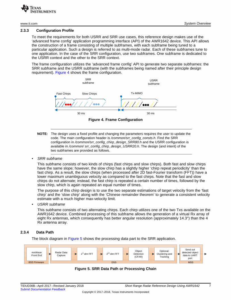
2.3.3 Configuration ProfileTo meet the requirements for both USRR and SRR use cases, this reference design makes use of the‘advanced frame config’ application programming interface (API) of the AWR1642 device. This API allowsthe construction of a frame consisting of multiple subframes, with each subframe being tuned to aparticular application. Such a design is referred to as multi-mode radar. Each of these subframes tune toone application. In the case of the SRR configuration, use two subframes. One subframe is dedicated tothe USRR context and the other to the SRR context.
The frame configuration utilizes the ‘advanced frame config’ API to generate two separate subframes: theSRR subframe and the USRR subframe (with the subframes being named after their principle designrequirement). Figure 4 shows the frame configuration.
Figure 4. Frame Configuration
NOTE: The design uses a fixed profile and changing the parameters requires the user to update thecode. The main configuration header is /common/srr_config_consts.h. Find the SRRconfiguration in /common/srr_config_chirp_design_SRR80.h and the USRR configuration isavailable in /common/ srr_config_chirp_design_USRR20.h. The design (and intent) of thetwo subframes are provided as follows.
• SRR subframeThis subframe consists of two kinds of chirps (fast chirps and slow chirps). Both fast and slow chirpshave the same slope; however, the slow chirp has a slightly higher ‘chirp repeat periodicity’ than thefast chirp. As a result, the slow chirps (when processed after 2D fast-Fourier transform (FFT)) have alower maximum unambiguous velocity as compared to the fast chirps. Note that the fast and slowchirps do not alternate; instead, the fast chirp is repeated a certain number of times, followed by theslow chirp, which is again repeated an equal number of times.The purpose of this chirp design is to use the two separate estimations of target velocity from the ‘fastchirp’ and the ‘slow chirp’ along with the ‘Chinese remainder theorem’ to generate a consistent velocityestimate with a much higher max-velocity limit.
• USRR subframeThis subframe consists of two alternating chirps. Each chirp utilizes one of the two Txs available on theAWR1642 device. Combined processing of this subframe allows the generation of a virtual Rx array ofeight Rx antennas, which consequently has better angular resolution (approximately 14.3°) than the 4Rx antenna array.
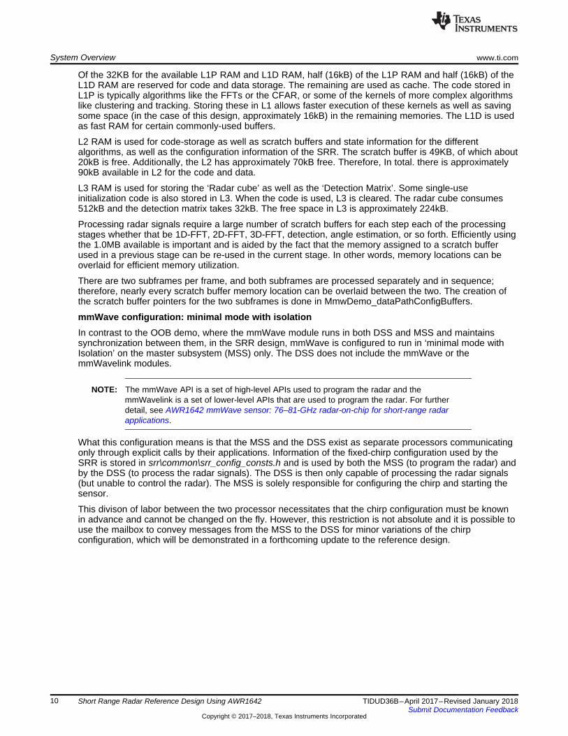
2.3.4 Data PathThe block diagram in Figure 5 shows the processing data part to the SRR application.
Figure 5. SRR Data Path or Processing Chain

Acquisition Period
Frame Period
Acquisition and 1st D FFT 2nd D FFT CFAR detection Post processingAzimuth and (X,Y)
estimationAcquisition and 1st D FFT
DSS:
Inter frame processing time
Send out dataMSS:
Copyright © 2017, Texas Instruments Incorporated
System Overview www.ti.com
8 TIDUD36B–April 2017–Revised January 2018Submit Documentation Feedback
Copyright © 2017–2018, Texas Instruments Incorporated
Short Range Radar Reference Design Using AWR1642
2.3.5 Chirp TimingFigure 6 shows the timing of the chirps and subsequent processing in the system.
Figure 6. Top Level Data Path Timing
Figure 6 shows the data path processing, which is described as follows.• The RF front end is configured by the BIST subsystem (BSS). The raw data obtained from the various
front end channels is taken by the C67x DSP subsystem (DSS) for processing.• Processing during the chirps as seen in Figure 6 consists of:
– 1D (range) FFT processing performed by the C674x that takes input from multiple receive antennaefrom the ADC buffer for every chirp (corresponding to the chirping pattern on the transmitantennae)
– Transferring transposed output into the L3 RAM by enhanced direct memory access (eDMA)• Processing during the idle or cool down period of the RF circuitry following the chirps until the next
chirping period, shown as Inter frame processing time in Figure 6. This processing consists of:– 2D (velocity) FFT processing performed by C674x that takes input from 1D output in L3 RAM and
performs FFT to give a (range, velocity) matrix in the L3 RAM. The processing also includes theCFAR detection in Doppler direction. CFAR detection in range direction uses the mmWave library.
– Peak grouping (for both Doppler and range) for the SRR subframe and Doppler for the USRRsubframe
– Direction of arrival (azimuth) estimation to map the X-Y location of object– Additional pruning based on the SNR and the 2D-FFT magnitude of the object to avoid ground
clutter– Clustering of detected objects using the dBScan algorithm for both SRR and USRR– Tracking of clusters using an extended Kalman filter for the SRR
For more details on the application flow and processing, see mmWave SDK User's Guide.
ClusteringClustering is performed using the dBscan algorithm [9] which is applied on the detected objects of both theSRR and the USRR subframes. The output of the clustering algorithm is the mean location of a clusterand its dimensions (assuming the cluster is a rectangle).
For the USRR subframe, the clustering output is sent as is to the graphical user interface (GUI). USRRclusters allow the grouping of dense point clouds to rectangles. In cross-traffic scenarios, these clusterscan be used to identify vehicles crossing the field of vision (FoV) of the radar.
For the SRR algorithm, the clustering output is used as the basis for the input to the tracking algorithm.The strongest object in the cluster is provided as the representative object to the tracking algorithm. Theintention here is essentially reduce the number of objects provided to the tracking algorithm and introducehysteresis, so that the trackers only track strong reflectors, and do not switch between adjacent reflectors.

www.ti.com System Overview
9TIDUD36B–April 2017–Revised January 2018Submit Documentation Feedback
Copyright © 2017–2018, Texas Instruments Incorporated
Short Range Radar Reference Design Using AWR1642
TrackingThe tracker is a fairly standard Extended Kalman Filter (EKF with four states [x, y, vx, vv] and three inputs[r, v, sin(θ)] or range, relative velocity, and sin of the azimuth). Compute the associated variances for theinputs using the associated signal-to-noise ratio (SNR) for each input. Use the Cramer-Rao lower bound(CRLB) formula for frequency variance to convert the SNR to a variance. The variance is lower-boundedby the resolution of the various inputs.
While the tracker is quite standard for an EKF, there are two functions in the tracker that can be modifiedbased on the requirements. The first is the ‘track initialization function’ (initNewTracker), where the initialparameters of the track are populated. In the SRR design, the assumption is that the velocity of the objectis only along the longitudinal axis. In other words, a vehicle with a relative velocity v is assumed to betravelling towards the radar with vx = 0 , and vv = v , which works well in long-range highway traffic, but isless effective in cross-traffic situations.
The second function is the ‘data association function’ (isTargetWithinDataAssociationThresh), whichassociates new measurements with existing tracks. Association essentially requires assumptions on themovement of objects in the scene, including maximum velocities, directions of motion, accelerations whenclose to the radar, and so forth.
eDMA configurationLarge-scale data movement between memories is accomplished in both the out-of-box (OOB) demo of themmWave SDK and the SRR using the eDMA. Using the eDMA is more efficient than using the processorto move data because, while the data movement is being completed, the DSP can continue to processdata. The major data transfers necessary in the OOB demo include:• Movement of ADC data from the ADC buffer to the DSP L2/L1 memory• Movement of 1D-FFT data from the DSP L1/L2 memory to the L3 memory to form the ‘radarcube
matrix’• Fetching the 1D-FFT data from L3 to do 2D FFT• Movement of the ‘sumAbs’ array from the L2/L1 to L3 to form the detection matrix• Movement of slices of the detection matrix in L3 to L2/L1 to do detection• Movement of 1D-FFT data from L3 to do angle estimation (after 2D-DFT)
Most of the eDMAs work on a ping-pong buffer, which means that as the ping buffer is being filled, thepong buffer can be used by the DSP for processing. The eDMA configuration in the SRR demo is verysimilar to the eDMA configuration on the OOB demo. The differences relate to the processing of twodifferent subframes, and the processing of the SRR subframe.
In order to process the two different subframes, the SRR demo simply doubles the number of number ofassigned eDMAs so that each subframe has its own subset of eDMAs to perform the necessary transfers.This method will not scale as the number of subframes increase, and it is recommended that if more than3 subframes are to be programmed, then one should reprogram the eDMAs after a frame is processed (asis done in the OOB demo).
To process the ‘max velocity enhancement’ subframe, the eDMAs listed as 2, 3, and 6 must be changed,so that they transfer twice as many chirps.
Memory allocationThe AWR1642 (PG 2.0) has the following memories on the DSP.1. L3 RAM of 768kB (PG 1.0 has 640 kB)2. L2 RAM of 256kB3. L1 RAM of 32kB each
The R4F has 512kB of code and data RAM. In the SRR design, the R4F is used only for configuration andfor the universal asynchronous receiver/transmitter (UART) or loop-voltage differential-signaling (LVDS)communication. The RF4 memory consumption and allocation are not of any concern to the design. TheDSP, therefore, is the main consumer of memory, for which the allocations are discussed below.
System Overview www.ti.com
10 TIDUD36B–April 2017–Revised January 2018Submit Documentation Feedback
Copyright © 2017–2018, Texas Instruments Incorporated
Short Range Radar Reference Design Using AWR1642
Of the 32KB for the available L1P RAM and L1D RAM, half (16kB) of the L1P RAM and half (16kB) of theL1D RAM are reserved for code and data storage. The remaining are used as cache. The code stored inL1P is typically algorithms like the FFTs or the CFAR, or some of the kernels of more complex algorithmslike clustering and tracking. Storing these in L1 allows faster execution of these kernels as well as savingsome space (in the case of this design, approximately 16kB) in the remaining memories. The L1D is usedas fast RAM for certain commonly-used buffers.
L2 RAM is used for code-storage as well as scratch buffers and state information for the differentalgorithms, as well as the configuration information of the SRR. The scratch buffer is 49KB, of which about20kB is free. Additionally, the L2 has approximately 70kB free. Therefore, In total. there is approximately90kB available in L2 for the code and data.
L3 RAM is used for storing the ‘Radar cube’ as well as the ‘Detection Matrix’. Some single-useinitialization code is also stored in L3. When the code is used, L3 is cleared. The radar cube consumes512kB and the detection matrix takes 32kB. The free space in L3 is approximately 224kB.
Processing radar signals require a large number of scratch buffers for each step each of the processingstages whether that be 1D-FFT, 2D-FFT, 3D-FFT, detection, angle estimation, or so forth. Efficiently usingthe 1.0MB available is important and is aided by the fact that the memory assigned to a scratch bufferused in a previous stage can be re-used in the current stage. In other words, memory locations can beoverlaid for efficient memory utilization.
There are two subframes per frame, and both subframes are processed separately and in sequence;therefore, nearly every scratch buffer memory location can be overlaid between the two. The creation ofthe scratch buffer pointers for the two subframes is done in MmwDemo_dataPathConfigBuffers.
mmWave configuration: minimal mode with isolationIn contrast to the OOB demo, where the mmWave module runs in both DSS and MSS and maintainssynchronization between them, in the SRR design, mmWave is configured to run in ‘minimal mode withIsolation’ on the master subsystem (MSS) only. The DSS does not include the mmWave or themmWavelink modules.
NOTE: The mmWave API is a set of high-level APIs used to program the radar and themmWavelink is a set of lower-level APIs that are used to program the radar. For furtherdetail, see AWR1642 mmWave sensor: 76–81-GHz radar-on-chip for short-range radarapplications.
What this configuration means is that the MSS and the DSS exist as separate processors communicatingonly through explicit calls by their applications. Information of the fixed-chirp configuration used by theSRR is stored in srr\common\srr_config_consts.h and is used by both the MSS (to program the radar) andby the DSS (to process the radar signals). The DSS is then only capable of processing the radar signals(but unable to control the radar). The MSS is solely responsible for configuring the chirp and starting thesensor.
This divison of labor between the two processor necessitates that the chirp configuration must be knownin advance and cannot be changed on the fly. However, this restriction is not absolute and it is possible touse the mailbox to convey messages from the MSS to the DSS for minor variations of the chirpconfiguration, which will be demonstrated in a forthcoming update to the reference design.

www.ti.com System Overview
11TIDUD36B–April 2017–Revised January 2018Submit Documentation Feedback
Copyright © 2017–2018, Texas Instruments Incorporated
Short Range Radar Reference Design Using AWR1642
Maximum velocity disambiguation in SRR subframeThe SRR subframe achieves a maximum unambiguous velocity of 90 kph by using signal processingtechniques that help disambiguate velocity. This method works by using two different estimates of velocityfrom the two kinds of chirps (‘fast chirps’ and ‘slow chirps’) transmitted in the SRR subframe. If the twovelocity estimates do not agree, then velocity disambiguation is necessary. To disambiguate, it isnecessary to rationalize the two velocity measurements and find out the disambiguation factor, k. If thenative maximum unambiguous velocity of the 'fast chirp' is vf , and that of the 'slow chirp' is vs, then afterthe disambiguation process, the disambiguated velocity would be 2kvf + v, where v is the native estimatedvelocity from the ‘fast chirps’.
The disambiguation process works by using the 'fast chirp' velocity to compute different disambiguatedvelocity hypotheses. This computation works by taking the 'fast chirp' velocity and adding 2kvf, wherek ∈ {–1,0,1} (an unwrapping process on the velocity estimate). These hypotheses are then converted toindices of the 'slow chirp' by finding the equivalent estimated velocities in the 'slow chirp' configuration(essentially, undoing the unwrapping using vs as the maximum unambiguous velocity).
If the index corresponding to one of the hypotheses has significant energy, then that hypothesis isconsidered to be valid. Disambiguation of up to 3x of the naive max-velocity is possible with this method;however, testing has only been done up to 90 kph.

Hardware, Software, Testing Requirements, and Test Results www.ti.com
12 TIDUD36B–April 2017–Revised January 2018Submit Documentation Feedback
Copyright © 2017–2018, Texas Instruments Incorporated
Short Range Radar Reference Design Using AWR1642
3 Hardware, Software, Testing Requirements, and Test Results
3.1 Required Hardware and SoftwareThe AWR1642 BoosterPack™ from Texas Instruments is an easy-to-use evaluation board for theAWR1642 mmWave sensing devices.
The short-range radar application runs on the AWR1642 EVM and connects to a visualization tool runningon a PC connected to the EVM over USB.
For details regarding usage of this board, see AWR1642 Evaluation Module (AWR1642BOOST) Single-Chip mmWave Sensing Solution.
For details regarding the visualization tool, see mmWave SDK User's Guide.
3.1.1 HardwareThe AWR1642 core design includes:• AWR1642 device: A single-chip, 77-GHz radar device with an integrated DSP• Power management network using a low-dropout linear regulator (LDO) and power management
integrated circuit (PMIC) DC/DC supply (TPS7A88, TPS7A8101-Q1, and LP87524B-Q1)• The EVM also hosts a device to assist with onboard emulation and UART emulation over a USB link
with the PC
3.1.2 Software and GUI
The associated software is hosted as the mmWave Demo in mmWave SDK distribution.
The GUI for the SRR TI design is located in the\ti\mmwave_sdk_01_01_00_02\packages\ti\demo\xwr16xx\gui path and is written in the Matlabprogramming language. As such, the GUI requires a specific Matlab runtime engine (v8.5.1 32-bit) toproperly install. The executable provided only works in a Windows operating system.
The first tab allows the user to configure the demo (see Figure 7). In the first tab (UART port options),UART ports can be configured (based on the device manager settings). If the radar is already running,there is no need to load the configuration, so the ‘reload configuration’ is not necessary when restartingthe GUI; otherwise, set it to start the radar.
The second tab configures the ranges on the GUI. Note that it only configures the GUI and not the radar.
The final tab has a list of record and replay options that allow the user to record and then replay UARTrecordings.

www.ti.com Hardware, Software, Testing Requirements, and Test Results
13TIDUD36B–April 2017–Revised January 2018Submit Documentation Feedback
Copyright © 2017–2018, Texas Instruments Incorporated
Short Range Radar Reference Design Using AWR1642
Figure 7. GUI Configuration
The default GUI starts as soon as the user presses the OK button. See Figure 8 for a screenshot of theGUI with the different components labelled.
Figure 8. GUI
Hardware, Software, Testing Requirements, and Test Results www.ti.com
14 TIDUD36B–April 2017–Revised January 2018Submit Documentation Feedback
Copyright © 2017–2018, Texas Instruments Incorporated
Short Range Radar Reference Design Using AWR1642
The Matlab GUI consists of five components.• X-Y scatter plot – Displays the positions of the point clouds, the tracks, and the cluster.• Doppler range plot – Displays the Doppler-range coordinates of the point cloud and the clusters.• Frame parameters – Displays the (fixed) parameters of the SRR reference design.• Legend – Description of the different kinds of points being displayed on the screen.• Display options – The features of the SRR reference design can make the display crowded and
sometimes difficult to understand. As such, different types of the point cloud can be enabled anddisabled at the user's discretion during demonstration. For example, during long stretches of openhighway, the user may only need to see the trackers. In heavy traffic, the USRR cloud makes moresense. In cases where there is cross traffic, the cluster output generates a better display of the trafficcrossing over. In general, TI recommends to leave on the trackers and the parking grid.
3.2 Testing and Results
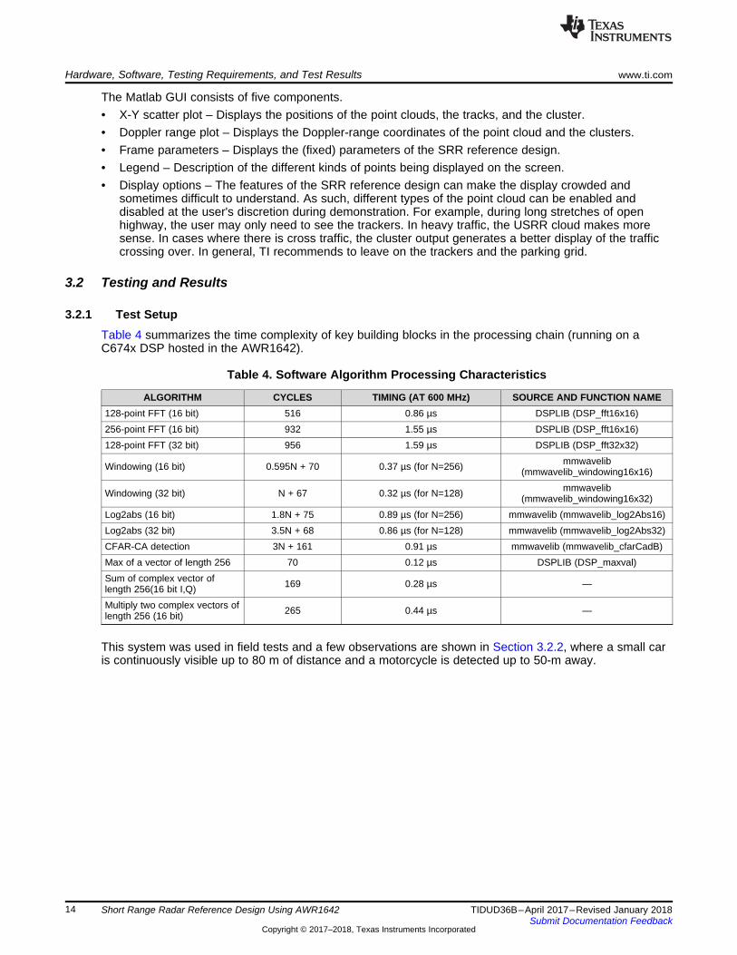
3.2.1 Test SetupTable 4 summarizes the time complexity of key building blocks in the processing chain (running on aC674x DSP hosted in the AWR1642).
Table 4. Software Algorithm Processing Characteristics
ALGORITHM CYCLES TIMING (AT 600 MHz) SOURCE AND FUNCTION NAME128-point FFT (16 bit) 516 0.86 µs DSPLIB (DSP_fft16x16)256-point FFT (16 bit) 932 1.55 µs DSPLIB (DSP_fft16x16)128-point FFT (32 bit) 956 1.59 µs DSPLIB (DSP_fft32x32)
Windowing (16 bit) 0.595N + 70 0.37 µs (for N=256) mmwavelib(mmwavelib_windowing16x16)
Windowing (32 bit) N + 67 0.32 µs (for N=128) mmwavelib(mmwavelib_windowing16x32)
Log2abs (16 bit) 1.8N + 75 0.89 µs (for N=256) mmwavelib (mmwavelib_log2Abs16)Log2abs (32 bit) 3.5N + 68 0.86 µs (for N=128) mmwavelib (mmwavelib_log2Abs32)CFAR-CA detection 3N + 161 0.91 µs mmwavelib (mmwavelib_cfarCadB)Max of a vector of length 256 70 0.12 µs DSPLIB (DSP_maxval)Sum of complex vector oflength 256(16 bit I,Q) 169 0.28 µs —
Multiply two complex vectors oflength 256 (16 bit) 265 0.44 µs —
This system was used in field tests and a few observations are shown in Section 3.2.2, where a small caris continuously visible up to 80 m of distance and a motorcycle is detected up to 50-m away.
www.ti.com Hardware, Software, Testing Requirements, and Test Results
15TIDUD36B–April 2017–Revised January 2018Submit Documentation Feedback
Copyright © 2017–2018, Texas Instruments Incorporated
Short Range Radar Reference Design Using AWR1642
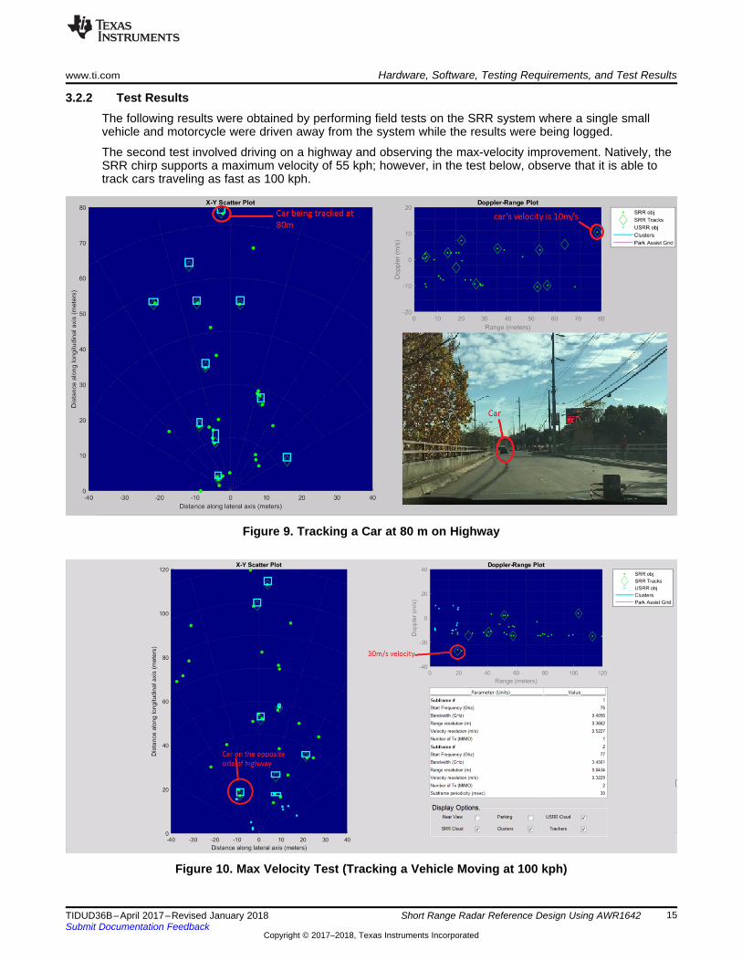
3.2.2 Test ResultsThe following results were obtained by performing field tests on the SRR system where a single smallvehicle and motorcycle were driven away from the system while the results were being logged.
The second test involved driving on a highway and observing the max-velocity improvement. Natively, theSRR chirp supports a maximum velocity of 55 kph; however, in the test below, observe that it is able totrack cars traveling as fast as 100 kph.
Figure 9. Tracking a Car at 80 m on Highway
Figure 10. Max Velocity Test (Tracking a Vehicle Moving at 100 kph)

Software Files www.ti.com
16 TIDUD36B–April 2017–Revised January 2018Submit Documentation Feedback
Copyright © 2017–2018, Texas Instruments Incorporated
Short Range Radar Reference Design Using AWR1642
4 Software FilesTo download the software files, see the design files at TIDEP-0092.
5 Related Documentation
1. Texas Instruments, AWR1642 Evaluation Module (AWR1642BOOST) Single-Chip mmWave SensingSolution
2. Texas Instruments, Programming Chirp Parameters in TI Radar Devices3. Texas Instruments, AWR1642 Single-Chip 77- and 79-GHz FMCW Radar Sensor4. Texas Instruments, AR14xx/16xx Technical Reference Manual5. Texas Instruments, AWR1642 Evaluation Board Design Database6. Texas Instruments, AWR1642BOOST Schematic, Assembly, and BOM7. Texas Instruments, mmWave SDK User's Guide8. Texas Instruments, AWR1642 mmWave sensor: 76–81-GHz radar-on-chip for short-range radar
applications
5.1 TrademarksBoosterPack is a trademark of Texas Instruments, Inc..ARM, Cortex are registered trademarks of ARM Limited.All other trademarks are the property of their respective owners.
6 About the AuthorANIL MANI is a system engineer at Texas Instruments where he is responsible for designing algorithmsfor the radar processing chain. Anil has been with TI since 2008 and has been involved in the design ofvarious products related to wireless communication.

www.ti.com Revision B History
17TIDUD36B–April 2017–Revised January 2018Submit Documentation Feedback
Copyright © 2017–2018, Texas Instruments Incorporated
Revision History
Revision B HistoryNOTE: Page numbers for previous revisions may differ from page numbers in the current version.
Changes from A Revision (May 2017) to B Revision ...................................................................................................... Page
• Removed 'Motorcycles' from list item under Features ; added 'Trucks'. ........................................................... 1• Added content to Features: "Objects 20-m Away Detectable With Resolution of 4.3 cm"....................................... 1• Added list item to Features: "Clustering and Tracking on Detected Outputs"..................................................... 1• Added more specific details and values regarding the TI SRR design in Section 1.2 .......................................... 2• Updated values and added specifications for both SRR and USRR in Key System Specifications ........................... 2• Updated values and added specifications for both SRR and USRR in Table 2 ................................................. 6• Changed stated primary goal of a maximum distance from 85 m to 80 m ........................................................ 6• Changed stated available IF bandwidth from 5 MHz to 6.25 MHz for the AWR1642 ............................................ 6• Changed the stated native maximum velocity of 30 mph to 55 kph ................................................................ 6• Changed the stated maximum unambiguous velocity for detection from 90 mph to 90 kph .................................... 6• Updated to specify that multi-mode capability has (since release) been implemented in the SRR design ................... 6• Updated values and added specifications for both SRR and USRR in Table 3 ................................................. 6• Updated all content in Section 2.3.3; added Figure 4 ................................................................................ 7• Added details to 'Peak grouping' list item: (for both Doppler and range) for the SRR subframe and the Doppler for the
USRR subframe ........................................................................................................................... 8• Added content for "Clustering" .......................................................................................................... 8• Added content to "Tracking" ............................................................................................................. 9• Added content for "eDMA configuration" ............................................................................................... 9• Added content for "Memory allocation"................................................................................................. 9• Added content for "mmWave configuration: minimal mode with isolation"....................................................... 10• Added content for "Maximum velocity disambiguation in SRR subframe" ....................................................... 11• Updated Section 3.1.2 title to Software and GUI and added content addressing the GUI..................................... 12• Added Figure 7........................................................................................................................... 13• Added Figure 8........................................................................................................................... 13• Updated Figure 9 ........................................................................................................................ 15• Updated Figure 10....................................................................................................................... 15

Revision A History www.ti.com
18 TIDUD36B–April 2017–Revised January 2018Submit Documentation Feedback
Copyright © 2017–2018, Texas Instruments Incorporated
Revision History
Revision A History
Changes from Original (April 2017) to A Revision .......................................................................................................... Page
• Changed Section 5 ..................................................................................................................... 16

IMPORTANT NOTICE FOR TI DESIGN INFORMATION AND RESOURCES
Texas Instruments Incorporated (‘TI”) technical, application or other design advice, services or information, including, but not limited to,reference designs and materials relating to evaluation modules, (collectively, “TI Resources”) are intended to assist designers who aredeveloping applications that incorporate TI products; by downloading, accessing or using any particular TI Resource in any way, you(individually or, if you are acting on behalf of a company, your company) agree to use it solely for this purpose and subject to the terms ofthis Notice.TI’s provision of TI Resources does not expand or otherwise alter TI’s applicable published warranties or warranty disclaimers for TIproducts, and no additional obligations or liabilities arise from TI providing such TI Resources. TI reserves the right to make corrections,enhancements, improvements and other changes to its TI Resources.You understand and agree that you remain responsible for using your independent analysis, evaluation and judgment in designing yourapplications and that you have full and exclusive responsibility to assure the safety of your applications and compliance of your applications(and of all TI products used in or for your applications) with all applicable regulations, laws and other applicable requirements. Yourepresent that, with respect to your applications, you have all the necessary expertise to create and implement safeguards that (1)anticipate dangerous consequences of failures, (2) monitor failures and their consequences, and (3) lessen the likelihood of failures thatmight cause harm and take appropriate actions. You agree that prior to using or distributing any applications that include TI products, youwill thoroughly test such applications and the functionality of such TI products as used in such applications. TI has not conducted anytesting other than that specifically described in the published documentation for a particular TI Resource.You are authorized to use, copy and modify any individual TI Resource only in connection with the development of applications that includethe TI product(s) identified in such TI Resource. NO OTHER LICENSE, EXPRESS OR IMPLIED, BY ESTOPPEL OR OTHERWISE TOANY OTHER TI INTELLECTUAL PROPERTY RIGHT, AND NO LICENSE TO ANY TECHNOLOGY OR INTELLECTUAL PROPERTYRIGHT OF TI OR ANY THIRD PARTY IS GRANTED HEREIN, including but not limited to any patent right, copyright, mask work right, orother intellectual property right relating to any combination, machine, or process in which TI products or services are used. Informationregarding or referencing third-party products or services does not constitute a license to use such products or services, or a warranty orendorsement thereof. Use of TI Resources may require a license from a third party under the patents or other intellectual property of thethird party, or a license from TI under the patents or other intellectual property of TI.TI RESOURCES ARE PROVIDED “AS IS” AND WITH ALL FAULTS. TI DISCLAIMS ALL OTHER WARRANTIES ORREPRESENTATIONS, EXPRESS OR IMPLIED, REGARDING TI RESOURCES OR USE THEREOF, INCLUDING BUT NOT LIMITED TOACCURACY OR COMPLETENESS, TITLE, ANY EPIDEMIC FAILURE WARRANTY AND ANY IMPLIED WARRANTIES OFMERCHANTABILITY, FITNESS FOR A PARTICULAR PURPOSE, AND NON-INFRINGEMENT OF ANY THIRD PARTY INTELLECTUALPROPERTY RIGHTS.TI SHALL NOT BE LIABLE FOR AND SHALL NOT DEFEND OR INDEMNIFY YOU AGAINST ANY CLAIM, INCLUDING BUT NOTLIMITED TO ANY INFRINGEMENT CLAIM THAT RELATES TO OR IS BASED ON ANY COMBINATION OF PRODUCTS EVEN IFDESCRIBED IN TI RESOURCES OR OTHERWISE. IN NO EVENT SHALL TI BE LIABLE FOR ANY ACTUAL, DIRECT, SPECIAL,COLLATERAL, INDIRECT, PUNITIVE, INCIDENTAL, CONSEQUENTIAL OR EXEMPLARY DAMAGES IN CONNECTION WITH ORARISING OUT OF TI RESOURCES OR USE THEREOF, AND REGARDLESS OF WHETHER TI HAS BEEN ADVISED OF THEPOSSIBILITY OF SUCH DAMAGES.You agree to fully indemnify TI and its representatives against any damages, costs, losses, and/or liabilities arising out of your non-compliance with the terms and provisions of this Notice.This Notice applies to TI Resources. Additional terms apply to the use and purchase of certain types of materials, TI products and services.These include; without limitation, TI’s standard terms for semiconductor products http://www.ti.com/sc/docs/stdterms.htm), evaluationmodules, and samples (http://www.ti.com/sc/docs/sampterms.htm).
Mailing Address: Texas Instruments, Post Office Box 655303, Dallas, Texas 75265Copyright © 2018, Texas Instruments Incorporated