show mls qos · show mls qos qos-1127 cisco ios quality of service solutions command reference...
TRANSCRIPT

show mls qos
QOS-1125Cisco IOS Quality of Service Solutions Command Reference
December 2010
show mls qosTo display multilayer switching (MLS) quality of service (QoS) information, use the show mls qos command in privileged EXEC mode.
show mls qos [{arp | ipv6 | ip | ipx | last | mac | module [module-number]} [interface interface-number | slot slot | null 0 | port-channel number | vlan vlan-id]] [detailed]
Syntax Description
Command Modes Privileged EXEC (#)
Command History
arp (Optional) Displays Address Resolution Protocol (ARP) information.
ipv6 (Optional) Displays IPv6 information.
ip (Optional) Displays information about the MLS IP status.
ipx (Optional) Displays information about the MLS Internetwork Packet Exchange (IPX) status.
last (Optional) Displays information about the last packet-policing.
mac (Optional) Displays information about the MAC address-based QoS status.
module module-number
(Optional) Specifies the module (slot) number; displays the global and per-interface QoS enabled and disabled settings and the global QoS counters.
interface (Optional) Interface type; valid values are ethernet, fastethernet, gigabitethernet, tengigabitethernet, ge-wan, pos, and atm.
interface-number (Optional) Module and port number; see the “Usage Guidelines” section for valid values.
slot slot (Optional) Specifies the slot number; displays the global and per-interface QoS enabled and disabled settings and the global QoS counters.
null 0 (Optional) Specifies the null interface; the only valid value is 0.
port-channel number
(Optional) Specifies the channel interface; there is a maximum of 64 values ranging from 1 to 282.
vlan vlan-id (Optional) Specifies the VLAN ID; valid values are from 1 to 4094.
detailed (Optional) Displays additional statistics.
Release Modification
12.2(14)SX This command was introduced on the Supervisor Engine 720.
12.2(17d)SXB This command was implemented on the Supervisor Engine 2 and integrated into Cisco IOS Release 12.2(17d)SXB.
12.2(18)SXE The arpand ipv6 keywords were added on the Supervisor Engine 720 only.
show mls qos
QOS-1126Cisco IOS Quality of Service Solutions Command Reference
December 2010
Usage Guidelines The ge-wan, pos, and atm interfaces are not supported on systems that are configured with a Supervisor Engine 720.
The interface-number argument designates the module and port number. Valid values for interface-number depend on the specified interface type and the chassis and module that are used. For example, if you specify a Gigabit Ethernet interface and have a 48-port 10/100BASE-T Ethernet module that is installed in a 13-slot chassis, valid values for the module number are from 1 to 13 and valid values for the port number are from 1 to 48.
The port-channel number values from 257 to 282 are supported on the Content Switching Module (CSM) and the Firewall Services Module (FWSM) only.
Catalyst 6500 Series Switches
In Cisco IOS Release 12.2(33)SXI and later releases, the following information is included in the output of the show mls qos command:
• Display of last 30-second counters.
• Display of peak 30-second counters over the last 5 minutes.
• Display of 5-minute average and peak bps rates.
The peak rates are monitored with 10-second resolution. Releases prior to Cisco IOS Release 12.2(33)SXI are monitored at 30-second resolution.
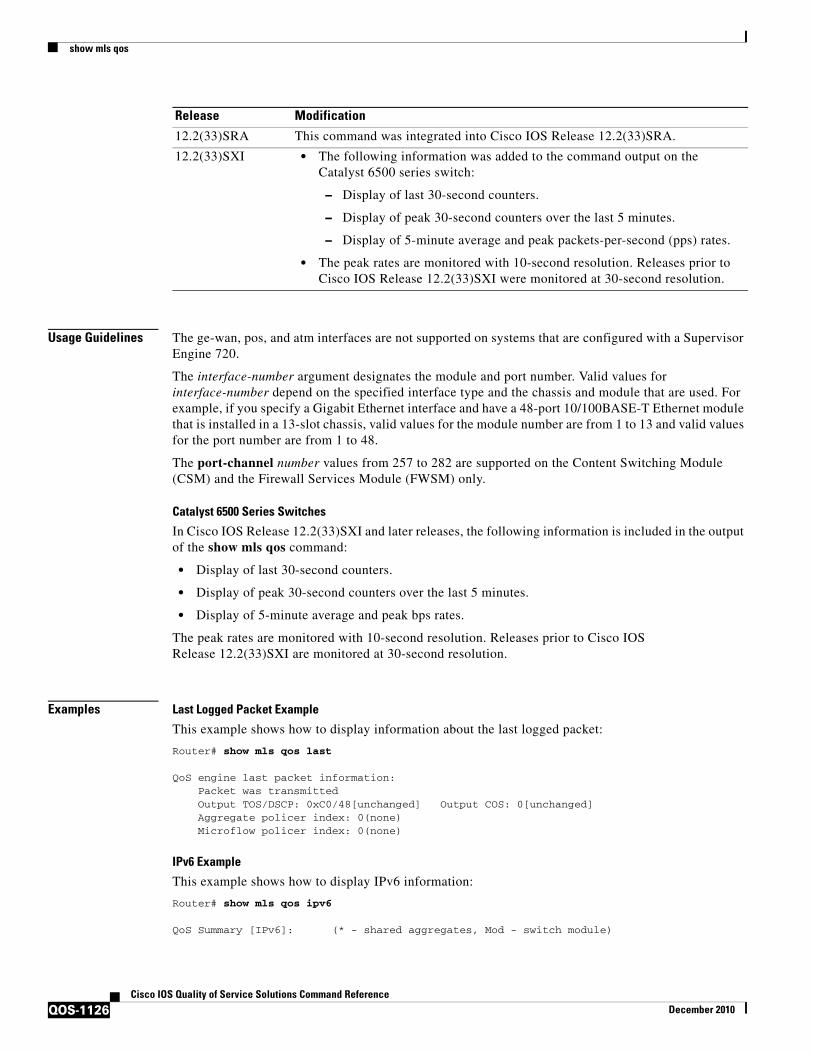
Examples Last Logged Packet Example
This example shows how to display information about the last logged packet:
Router# show mls qos last
QoS engine last packet information: Packet was transmitted Output TOS/DSCP: 0xC0/48[unchanged] Output COS: 0[unchanged] Aggregate policer index: 0(none) Microflow policer index: 0(none)
IPv6 Example
This example shows how to display IPv6 information:
Router# show mls qos ipv6
QoS Summary [IPv6]: (* - shared aggregates, Mod - switch module)
12.2(33)SRA This command was integrated into Cisco IOS Release 12.2(33)SRA.
12.2(33)SXI • The following information was added to the command output on the Catalyst 6500 series switch:
– Display of last 30-second counters.
– Display of peak 30-second counters over the last 5 minutes.
– Display of 5-minute average and peak packets-per-second (pps) rates.
• The peak rates are monitored with 10-second resolution. Releases prior to Cisco IOS Release 12.2(33)SXI were monitored at 30-second resolution.
Release Modification

show mls qos
QOS-1127Cisco IOS Quality of Service Solutions Command Reference
December 2010
Int Mod Dir Class-map DSCP Agg Trust Fl AgForward-By AgPoliced-By Id Id------------------------------------------------------------------------------
All 7 - Default 0 0* No 0 189115356 0
Supervisor Engine 720 Example
This example shows how to display QoS information:
Router# show mls qos
QoS is enabled globallyMicroflow policing is enabled globallyQoS ip packet dscp rewrite enabled globally
QoS is disabled on the following interfaces:Fa6/3 Fa6/4
QoS DSCP-mutation map is enabled on the following interfaces:Fa6/5Vlan or Portchannel(Multi-Earl) policies supported: YesEgress policies supported: Yes
----- Module [5] -----QoS global counters:Total packets: 164IP shortcut packets: 0Packets dropped by policing: 0IP packets with TOS changed by policing: 0IP packets with COS changed by policing: 0Non-IP packets with COS changed by policing: 0MPLS packets with EXP changed by policing: 0
Supervisor Engine 2 Example
This example shows the output if you do not enter any keywords:
Router# show mls qos
QoS is enabled globally Microflow QoS is enabled globally
QoS global counters: Total packets: 217500 IP shortcut packets: 344 Packets dropped by policing: 344 IP packets with TOS changed by policing 18323 IP packets with COS changed by policing 1602 Non-IP packets with COS changed by policing 0
Catalyst 6500 Series Switches Example
The show mls qos command output in Cisco IOS Release 12.2(33)SXI and later releases contains more packet counter information than in previous releases.
This example shows the Cisco IOS Release 12.2(33)SXI output with the detailed keyword:
Router# show mls qos detailed
QoS is enabled globally Policy marking depends on port_trust QoS ip packet dscp rewrite enabled globally Input mode for GRE Tunnel is Pipe mode
show mls qos
QOS-1128Cisco IOS Quality of Service Solutions Command Reference
December 2010
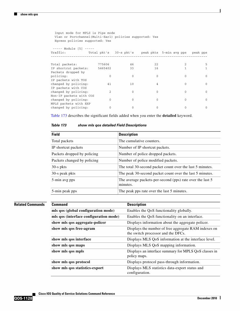
Input mode for MPLS is Pipe mode Vlan or Portchannel(Multi-Earl) policies supported: Yes Egress policies supported: Yes
----- Module [5] -----Traffic: Total pkt's 30-s pkt's peak pkts 5-min avg pps peak pps-----------------------------------------------------------------------------------
Total packets: 775606 46 22 2 5IP shortcut packets: 5465402 33 16 1 1Packets dropped by policing: 0 0 0 0 0IP packets with TOS changed by policing: 41 10 4 0 0IP packets with COS changed by policing: 2 0 0 0 0Non-IP packets with COS changed by policing: 0 0 0 0 0MPLS packets with EXP changed by policing: 0 0 0 0 0
Table 173 describes the significant fields added when you enter the detailed keyword.
Related Commands
Table 173 show mls qos detailed Field Descriptions
Field Description
Total packets The cumulative counters.
IP shortcut packets Number of IP shortcut packets.
Packets dropped by policing Number of police dropped packets.
Packets changed by policing Number of police modified packets.
30-s pkts The total 30-second packet count over the last 5 minutes.
30-s peak pkts The peak 30-second packet count over the last 5 minutes.
5-min avg pps The average packets-per-second (pps) rate over the last 5 minutes.
5-min peak pps The peak pps rate over the last 5 minutes.
Command Description
mls qos (global configuration mode) Enables the QoS functionality globally.
mls qos (interface configuration mode) Enables the QoS functionality on an interface.
show mls qos aggregate-policer Displays information about the aggregate policer.
show mls qos free-agram Displays the number of free aggregate RAM indexes on the switch processor and the DFCs.
show mls qos interface Displays MLS QoS information at the interface level.
show mls qos maps Displays MLS QoS mapping information.
show mls qos mpls Displays an interface summary for MPLS QoS classes in policy maps.
show mls qos protocol Displays protocol pass-through information.
show mls qos statistics-export Displays MLS statistics data-export status and configuration.
show mls qos aggregate policer
QOS-1129Cisco IOS Quality of Service Solutions Command Reference
December 2010
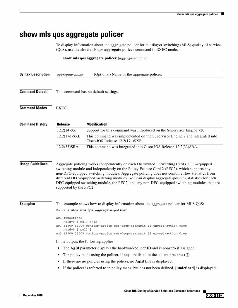
show mls qos aggregate policerTo display information about the aggregate policer for multilayer switching (MLS) quality of service (QoS), use the show mls qos aggregate policer command in EXEC mode.
show mls qos aggregate policer [aggregate-name]
Syntax Description
Command Default This command has no default settings.
Command Modes EXEC
Command History
Usage Guidelines Aggregate policing works independently on each Distributed Forwarding Card (DFC)-equipped switching module and independently on the Policy Feature Card 2 (PFC2), which supports any non-DFC-equipped switching modules. Aggregate policing does not combine flow statistics from different DFC-equipped switching modules. You can display aggregate-policing statistics for each DFC-equipped switching module, the PFC2, and any non-DFC-equipped switching modules that are supported by the PFC2.
Examples This example shows how to display information about the aggregate policer for MLS QoS:
Router# show mls qos aggregate-policer
ag1 (undefined) AgId=0 [ pol1 pol2 ]ag2 64000 64000 conform-action set-dscp-transmit 56 exceed-action drop AgId=0 [ pol3 ]ag3 32000 32000 conform-action set-dscp-transmit 34 exceed-action drop
In the output, the following applies:
• The AgId parameter displays the hardware-policer ID and is nonzero if assigned.
• The policy maps using the policer, if any, are listed in the square brackets ([]).
• If there are no policies using the policer, no AgId line is displayed.
• If the policer is referred to in policy maps, but has not been defined, [undefined] is displayed.
aggregate-name (Optional) Name of the aggregate policer.
Release Modification
12.2(14)SX Support for this command was introduced on the Supervisor Engine 720.
12.2(17d)SXB This command was implemented on the Supervisor Engine 2 and integrated into Cisco IOS Release 12.2(17d)SXB.
12.2(33)SRA This command was integrated into Cisco IOS Release 12.2(33)SRA.

show mls qos aggregate policer
QOS-1130Cisco IOS Quality of Service Solutions Command Reference
December 2010
Related Commands Command Description
mls qos aggregate-policer
Defines a named aggregate policer for use in policy maps.

show mls qos free-agram
QOS-1131Cisco IOS Quality of Service Solutions Command Reference
December 2010
show mls qos free-agramTo display the number of free aggregate RAM indexes on the switch processor and the Distributed Forwarding Cards (DFCs), use the show mls qos free-agram command in EXEC mode.
show mls qos free-agram
Syntax Description This command has no arguments or keywords.
Command Default This command has no default settings.
Command Modes EXEC
Command History
Examples This example shows how to display the number of free aggregate RAM indexes on the switch processor and the DFCs:
Router# show mls qos free-agram
Total Number of Available AG RAM indices : 1023
Module [1] Free AGIDs : 1023
Module [6] Free AGIDs : 1023
Release Modification
12.2(18)SXD Support for this command was introduced on the Supervisor Engine 720 and the Supervisor Engine 2.
12.2(33)SRA This command was integrated into Cisco IOS Release 12.2(33)SRA.

show mls qos interface
QOS-1132Cisco IOS Quality of Service Solutions Command Reference
December 2010
show mls qos interfaceTo display Multilayer Switching (MLS) quality of service (QoS) information at the interface level, use the show mls qos interface command in privileged EXEC mode.
show mls qos interface [interface-id] [policers]
Syntax Description
Command Modes Privileged EXEC
Command History
Usage Guidelines Use the show mls qos interface command without keywords to display parameters for all interfaces.
Use the show mls qos interface interface-id command to display the parameters for a specific interface.
On most Cisco switch platforms, the global command, "(no) mls qos", is used to toggle the MLS QoS state to be enabled or disabled. When MLS QoS is disabled globally, the CoS/IP Precidence/DSCP values for all traffic passing through the switch will not be modified. On the other hand, if MLS QoS is enabled, then by default all interfaces will be in an untrusted state, which means all incoming CoS/IP Prec/DSCP values will be remarked down to 0.
Cisco 2600 and Cisco 3600 Series Switches
Becuase the (no) mls qos global command is not supported for the Cisco_2600 or Csico_3600 series switches, this presents a unique situationregarding the default trust state for the interface.
By default, when there is no "mls qos" related commands configured under an interface on the Cisco_2600 or Cisco_3600 series switches, the CoS/IP Prec/DSCP value of all incoming traffic will not be remarked as it passes through the switch. This has the same result as when MLS QoS is disabled on other Cisco switches.
interface-id (Optional) Specifies the interface for which QoS information is to be displayed.
policers (Optional) Displays all the policers configured on the interface, their settings, and the number of policers unassigned.
Release Modification
12.1(6)EA2 This command was introduced.
12.2(15)ZJ This command was implemented on the following platforms: Cisco 2600 series, Cisco 3600 series, and Cisco 3700 series routers.
12.3(4)T This command was integrated into Cisco IOS Release 12.3(4)T on the following platforms: Cisco 2600 series, Cisco 3600 series, and Cisco 3700 series routers.
12.2(33)SRA This command was integrated into Cisco IOS Release 12.2(33)SRA.
12.2SX This command is supported in the Cisco IOS Release 12.2SX train. Support in a specific 12.2SX release of this train depends on your feature set, platform, and platform hardware.

show mls qos interface
QOS-1133Cisco IOS Quality of Service Solutions Command Reference
December 2010
Examples The following is sample output from the show mls qos interface fastethernet0/1 command:
Router# show mls qos interface fastethernet0/1
FastEthernet0/1trust state: trust cosCOS override: disdefault COS: 0
The following example shows that there is no mls QoS command configured on the interface. the CoS/IP Precidence/DSCP values of incoming traffic will not be remarked as it passes through the switch.
Router# show mls qos interface f1/1FastEthernet1/1trust state: none <<<trust mode: none <<<COS override: disdefault COS: 0pass-through: none
Related Commands Command Description
mls qos cos Defines the default MLS CoS value of a port or assigns the default CoS value to all incoming packets on the port.
mls qos map Defines the MLS CoS-to-DSCP map and DSCP-to-CoS map.
mls qos trust Configures the MLS port trust state and classifies traffic by an examination of the CoS or DSCP value.

show mls qos maps
QOS-1134Cisco IOS Quality of Service Solutions Command Reference
December 2010
show mls qos mapsTo display multilayer switching (MLS) quality of service (QoS) mapping information, use the show mls qos maps command in privileged EXEC mode.
Cisco 2600, 3660, 3700, 3845, 7200, 7400, and 7500 Series Routers
show mls qos maps [cos-dscp | dscp-cos]
Cisco 7600 Series Router and Catalyst 6500 Series Switch
show mls qos maps [cos-dscp | cos-mutation | dscp-cos | dscp-exp | dscp-mutation | exp-dscp | exp-mutation | ip-prec-dscp | policed-dscp]
Syntax Description
Command Default All MLS QoS maps are displayed.
Command Modes Privileged EXEC (#)
Command History
cos-dscp (Optional) Displays the class of service (CoS)-to-differentiated services code point (DSCP) map.
dscp-cos (Optional) Displays the DSCP-to-CoS map.
cos-mutation (Optional) Displays the CoS-mutation map.
dscp-exp (Optional) Displays the DSCP-to-exp map.
dscp-mutation (Optional) Displays the DSCP-mutation map.
exp-dscp (Optional) Displays the exp-to-DSCP map.
exp-mutation (Optional) Displays the exp-mutation map.
ip-prec-dscp (Optional) Displays the IP-precedence-to-DSCP map.
policed-dscp (Optional) Displays the policed-DSCP map.
Release Modification
12.1(6)EA2 This command was introduced.
12.2(14)SX This command was implemented on the Cisco 7600 series routers.
12.2(15)ZJ This command was implemented on the following platforms: Cisco 2600 series routers, Cisco 3600 series routers, and Cisco 3700 series routers.
12.2(17b)SXA This command was changed to support the cos-mutation, exp-dscp, and exp-mutation keywords.
12.2(33)SRA This command was integrated into Cisco IOS Release 12.2(33)SRA.
12.3(4)T This command was integrated into Cisco IOS Release 12.3(4)T on the following platforms: Cisco 2600 series, Cisco 3600 series, and Cisco 3700 series routers.
12.2(33)SXI Support was added for all map type keywords.
show mls qos maps
QOS-1135Cisco IOS Quality of Service Solutions Command Reference
December 2010
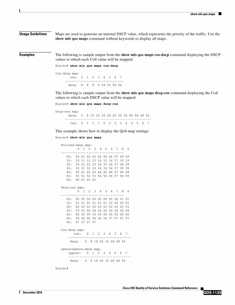
Usage Guidelines Maps are used to generate an internal DSCP value, which represents the priority of the traffic. Use the show mls qos maps command without keywords to display all maps.
Examples The following is sample output from the show mls qos maps cos-dscp command displaying the DSCP values to which each CoS value will be mapped:
Router# show mls qos maps cos-dscp
Cos-dscp map: cos: 0 1 2 3 4 5 6 7 -------------------------------- dscp: 8 8 8 8 24 32 56 56
The following is sample output from the show mls qos maps dscp-cos command displaying the CoS values to which each DSCP value will be mapped:
Router# show mls qos maps dscp-cos
Dscp-cos map: dscp: 0 8 10 16 18 24 26 32 34 40 46 48 56 ----------------------------------------------- cos: 0 1 1 1 2 2 3 3 4 4 5 6 7
This example shows how to display the QoS-map settings:
Router# show mls qos maps
Policed-dscp map: 0 1 2 3 4 5 6 7 8 9 ---------------------------------- 00: 00 01 02 03 04 05 06 07 08 09 10: 10 11 12 13 14 15 16 17 18 19 20: 20 21 22 23 24 25 26 27 28 29 30: 30 31 32 33 34 35 36 37 38 39 40: 40 41 42 43 44 45 46 47 48 49 50: 50 51 52 53 54 55 56 57 58 59 60: 60 61 62 63
Dscp-cos map: 0 1 2 3 4 5 6 7 8 9 ---------------------------------- 00: 00 00 00 00 00 00 00 00 01 01 10: 01 01 01 01 01 01 02 02 02 02 20: 02 02 02 02 03 03 03 03 03 03 30: 03 03 04 04 04 04 04 04 04 04 40: 05 05 05 05 05 05 05 05 06 06 50: 06 06 06 06 06 06 07 07 07 07 60: 07 07 07 07
Cos-dscp map: cos: 0 1 2 3 4 5 6 7 ---------------------------------- dscp: 0 8 16 24 32 40 48 56
IpPrecedence-dscp map: ipprec: 0 1 2 3 4 5 6 7 ---------------------------------- dscp: 0 8 16 24 32 40 48 56
Router#

show mls qos maps
QOS-1136Cisco IOS Quality of Service Solutions Command Reference
December 2010
In the policed DSCP and DSCP-CoS map displays, the new DSCP or CoS values are shown in the body of the table. The decade of the original DSCP value is shown in the left-side vertical column, and the units digit is in the top row. For example, the DSCP-CoS map indicates that if the original DSCP value is between 32 and 39, the CoS will be set to 4.
The CoS-DSCP and IP precedence-DSCP maps display the DSCP values to which each CoS or IP precedence value will be mapped. For example, the IP precedence-DSCP map indicates that if the original IP precedence value is 3, the DSCP will be set to 24.
This example shows how to verify the configuration of DSCP-mutation mapping:
Router# show mls qos maps | begin DSCP mutation
DSCP mutation map mutmap1: (dscp= d1d2) d1 : d2 0 1 2 3 4 5 6 7 8 9 ------------------------------------- 0 : 00 01 02 03 04 05 06 07 08 09 1 : 10 11 12 13 14 15 16 17 18 19 2 : 20 21 22 23 24 25 26 27 28 29 3 : 08 31 32 33 34 35 36 37 38 39 4 : 40 41 42 43 44 45 46 47 48 49 <...Output Truncated...>Router#
In the DSCP mutation map display, the marked-down DSCP values are shown in the body of the table. The first digit (d1) of the original DSCP value is in the left-side vertical column labeled d1, and the second digit (d2) is in the top row. For example, a DSCP value of 30 maps to a new DSCP value of 08.
Related Commands Command Description
mls qos map Defines the CoS-to-DSCP map and DSCP-to-CoS map.
mls qos map cos-dscp Defines the ingress CoS-to-DSCP map for trusted interfaces.
mls qos map cos-mutation
Maps a packet’s CoS to a new CoS value.
mls qos map dscp-cos Defines an egress DSCP-to-CoS map.
mls qos map dscp-mutation
Defines a named DSCP mutation map.
mls qos map ip-prec-dscp
Defines an ingress IP precedence-to-DSCP map for trusted interfaces.
mls qos map policed-dscp
Sets the mapping of policed DSCP values to marked-down DSCP values.

show mls qos mpls
QOS-1137Cisco IOS Quality of Service Solutions Command Reference
December 2010
show mls qos mplsTo display an interface summary for Multiprotocol Label Switching (MPLS) quality of service (QoS) classes in policy maps, use the show mls qos mpls command in user EXEC or privileged EXEC mode.
show mls qos mpls [interface-type interface-number | module slot]
Syntax Description
Command Modes User EXECPrivileged EXEC
Command History
Usage Guidelines This command is supported in PFC3BXL or PFC3B mode only.
The interface-number argument designates the module and port number. Valid values for interface-number depend on the specified interface type and the chassis and module that are used. For example, if you specify a Gigabit Ethernet interface and have a 48-port 10/100BASE-T Ethernet module that is installed in a 13-slot chassis, valid values for the module number are from 1 to 13 and valid values for the port number are from 1 to 48.
Examples The following example shows an interface summary for MPLS QoS classes in policy maps:
Router# show mls qos mpls
QoS Summary [MPLS]: (* - shared aggregates, Mod - switch module)Int Mod Dir Class-map DSCP Agg Trust Fl AgForward-By AgPoliced-By Id Id ---------------------------------------------------------------------------------------------------------------------- Fa3/38 5 In exp2 0 1 dscp 0 378900 0 Fa3/41 5 In exp4 0 3 dscp 0 0 0All 5 - Default 0 0* No 0 1191011240 0
interface-typeinterface-number
(Optional) Interface type; valid values are the following:
• fastethernet
• gigabitethernet
• tengigabitethernet.
(Optional) Module and port number; see the “Usage Guidelines” section for valid values.
module slot (Optional) Specifies the module slot number.
Release Modification
12.2(17a)SX This command was introduced on the Supervisor Engine 720.
12.2(33)SRB This command was integrated into Cisco IOS Release 12.2(33)SRB.

show mls qos mpls
QOS-1138Cisco IOS Quality of Service Solutions Command Reference
December 2010
Table 174 describes the significant fields shown in the display.
Related Commands
Table 174 show mls qos mpls Field Descriptions
Field Description
QoS Summary [MPLS]: (* - shared aggregates, Mod - switch module)
Shows if there are any shared aggregate policers, indicated by *, and the type of module.
Int Mod Dir Class-map DSCP Agg Trust Fl AgForward-By AgPoliced-By
Provides the column headings for the following lines in the display. These include interface name and number, module number, direction, class-map name, and DSCP value.
Fa3/38 5 In exp2 0 1 dscp 0 378900 0 Provides the following information:
• Fa3/38—Interface name and number.
• 5—Module number in the chassis.
• In—Direction of the policy applied (In = ingress).
• exp2—Class map configured in the policy.
• 0—Differentiated Services Code Point (DSCP) value.
• 1—Policer ID assigned to that class map.
• dscp—Trust value configured on the port. In this example, the value is trusting on DSCP.
• 0—The flow ID if the flow policer is configured.
• 378900—The aggregate forwarded bytes, meaning the forwarded traffic.
• 0—The aggregate policed bytes, meaning this traffic has been subjected to policing.
All 5 - Default 0 0* No 0 1191011240 0 The total of the preceding lines including the aggregate forwarded and aggregate policed bytes.
Command Description
mls qos exp-mutation Attaches an egress-EXP mutation map to the interface.
mls qos map exp-dscp Defines the ingress EXP value to the internal DSCP map.
mls qos map exp-mutation
Maps a packet’s EXP to a new EXP value.

show mls qos protocol
QOS-1139Cisco IOS Quality of Service Solutions Command Reference
December 2010
show mls qos protocolTo display protocol pass-through information, use the show mls qos protocol command in EXEC mode.
show mls qos protocol [module number]
Syntax Description
Command Default This command has no default settings.
Command Modes EXEC
Command History
Examples This example shows how to display protocol pass-through information:
Router# show mls qos protocol
RIP : Passthru mode OSPF : Passthru modeND : Policing mode Cir = 32000 Burst = 1000----- Module [5] ----- Routing protocol RIP is using AgId 0* Routing protocol OSPF is using AgId 0*Routing protocol ND is using AgId 1----- Module [6] ----- Routing protocol RIP is using AgId 0* Routing protocol OSPF is using AgId 0*
Related Commands
module number (Optional) Specifies the module number.
Release Modification
12.2(17a)SX Support for this command was introduced on the Supervisor Engine 720.
12.2(18)SXE Support for this command was introduced on the Supervisor Engine 2 but does not support Address Resolution Protocol (ARP), Integrated Intermediate System-to-Intermediate System (IS-IS), or Enhanced Interior Gateway Routing Protocol (EIGRP).
Support for neighbor discovery protocol packets was added on the Supervisor Engine 720 only.
12.2(33)SRA This command was integrated into Cisco IOS Release 12.2(33)SRA.
Command Description
mls qos protocol Defines the routing-protocol packet policing.

show mls qos queuing interface
QOS-1140Cisco IOS Quality of Service Solutions Command Reference
December 2010
show mls qos queuing interfaceTo display the queueing statistics of an interface, use the show mls qos queuing interface command in user EXEC mode.
show mls qos queuing interface {type | vlan }
Syntax Description
Command Modes User EXEC (>)
Command History
Usage Guidelines Cisco 7600 Series Routers
The pos, atm, and ge-wan interfaces are supported on Cisco 7600 series routers that are configured with a Supervisor Engine 2 only.
The type number argument used with the interface keyword designates the module and port number. Valid values depend on the specified interface type and the chassis and module that are used. For example, if you specify a Gigabit Ethernet interface and have a 48-port 10/100BASE-T Ethernet module installed in a 13-slot chassis, valid values for the module number are from 1 to 13 and valid values for the port number are from 1 to 48.
Use the show qm-sp port-data command to verify the values that are programmed in the hardware.
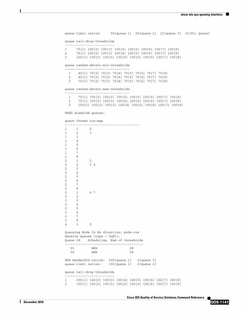
Examples The following example shows sample output from the show mls qos queuing interface gigabitethernet 5/1 command on the Endor (RSP720-10G) card.
Router# show mls qos queuing interface gig5/1
Weighted Round-Robin Port QoS is enabled Port is untrusted Extend trust state: not trusted [COS = 0] Default COS is 0 Queueing Mode In Tx direction: mode-cos Transmit queues [type = 1p3q8t]: Queue Id Scheduling Num of thresholds ----------------------------------------- 01 WRR 08 02 WRR 08 03 WRR 08 04 Priority 01WRR bandwidth ratios: 100[queue 1] 150[queue 2] 200[queue 3]
type Interface type.
For Cisco 7600 series routers, the valid interface types are ethernet, fastethernet, gigabitethernet, tengigabitethernet, pos, atm, and ge-wan.
vlan Specifies the VLAN identification number; valid values are from 1 to 4094.
Release Modification
15.0(1)S This command was introduced on LAN cards on Cisco 7600 Series Routers.
show mls qos queuing interface
QOS-1141Cisco IOS Quality of Service Solutions Command Reference
December 2010
queue-limit ratios: 50[queue 1] 20[queue 2] 15[queue 3] 15[Pri Queue]
queue tail-drop-thresholds -------------------------- 1 70[1] 100[2] 100[3] 100[4] 100[5] 100[6] 100[7] 100[8] 2 70[1] 100[2] 100[3] 100[4] 100[5] 100[6] 100[7] 100[8] 3 100[1] 100[2] 100[3] 100[4] 100[5] 100[6] 100[7] 100[8]
queue random-detect-min-thresholds ---------------------------------- 1 40[1] 70[2] 70[3] 70[4] 70[5] 70[6] 70[7] 70[8] 2 40[1] 70[2] 70[3] 70[4] 70[5] 70[6] 70[7] 70[8] 3 70[1] 70[2] 70[3] 70[4] 70[5] 70[6] 70[7] 70[8]
queue random-detect-max-thresholds ---------------------------------- 1 70[1] 100[2] 100[3] 100[4] 100[5] 100[6] 100[7] 100[8] 2 70[1] 100[2] 100[3] 100[4] 100[5] 100[6] 100[7] 100[8] 3 100[1] 100[2] 100[3] 100[4] 100[5] 100[6] 100[7] 100[8]
WRED disabled queues:
queue thresh cos-map --------------------------------------- 1 1 0 1 2 1 1 3 1 4 1 5 1 6 1 7 1 8 2 1 2 2 2 3 4 2 3 2 4 2 5 2 6 2 7 2 8 3 1 6 7 3 2 3 3 3 4 3 5 3 6 3 7 3 8 4 1 5
Queueing Mode In Rx direction: mode-cos Receive queues [type = 2q8t]: Queue Id Scheduling Num of thresholds ----------------------------------------- 01 WRR 08 02 WRR 08
WRR bandwidth ratios: 100[queue 1] 0[queue 2] queue-limit ratios: 100[queue 1] 0[queue 2]
queue tail-drop-thresholds -------------------------- 1 100[1] 100[2] 100[3] 100[4] 100[5] 100[6] 100[7] 100[8] 2 100[1] 100[2] 100[3] 100[4] 100[5] 100[6] 100[7] 100[8]

show mls qos queuing interface
QOS-1142Cisco IOS Quality of Service Solutions Command Reference
December 2010
queue random-detect-min-thresholds ---------------------------------- 1 40[1] 40[2] 50[3] 50[4] 50[5] 50[6] 50[7] 50[8] 2 100[1] 100[2] 100[3] 100[4] 100[5] 100[6] 100[7] 100[8]
queue random-detect-max-thresholds ---------------------------------- 1 70[1] 80[2] 90[3] 100[4] 100[5] 100[6] 100[7] 100[8] 2 100[1] 100[2] 100[3] 100[4] 100[5] 100[6] 100[7] 100[8]
queue thresh cos-map --------------------------------------- 1 1 0 1 2 3 4 5 6 7 1 2 1 3 1 4 1 5 1 6 1 7 1 8 2 1 2 2 2 3 2 4 2 5 2 6 2 7 2 8
Packets dropped on Transmit:
queue dropped [cos-map] --------------------------------------------- 1 0 [0 1 ] 2 0 [2 3 4 ] 3 0 [6 7 ] 4 0 [5 ]
Packets dropped on Receive: BPDU packets: 0
queue dropped [cos-map] --------------------------------------------------- 1 0 [0 1 2 3 4 5 6 7 ] 2 0 []...
Related Commands Command Description
mls qos cos Defines the default MLS CoS value of a port or assigns the default CoS value to all incoming packets on the port.
mls qos map Defines the MLS CoS-to-DSCP map and DSCP-to-CoS map.
mls qos trust Configures the MLS port trust state and classifies traffic by an examination of the CoS or DSCP value.
custom-queue-list Assigns a custom queue list to an interface.

show mls qos queuing interface
QOS-1143Cisco IOS Quality of Service Solutions Command Reference
December 2010
fair-queue (class-default)
Specifies the number of dynamic queues to be reserved for use by the class-default class as part of the default class policy.
fair-queue (WFQ) Enables WFQ for an interface.
priority-group Assigns the specified priority list to an interface.
random-detect flow Enables flow-based WRED.
random-detect (interface)
Enables WRED or DWRED.
random-detect (per VC)
Enables per-VC WRED or per-VC DWRED.
show frame-relay pvc Displays information and statistics about WFQ for a VIP-based interface.
show policy-map interface
Displays the configuration of all classes configured for all service policies on the specified interface or displays the classes for the service policy for a specific PVC on the interface.
show qm-sp port-data
Displays information about the QoS manager switch processor.
show queueing Lists all or selected configured queueing strategies.
Command Description
show mls qos statistics-export info
QOS-1144Cisco IOS Quality of Service Solutions Command Reference
December 2010
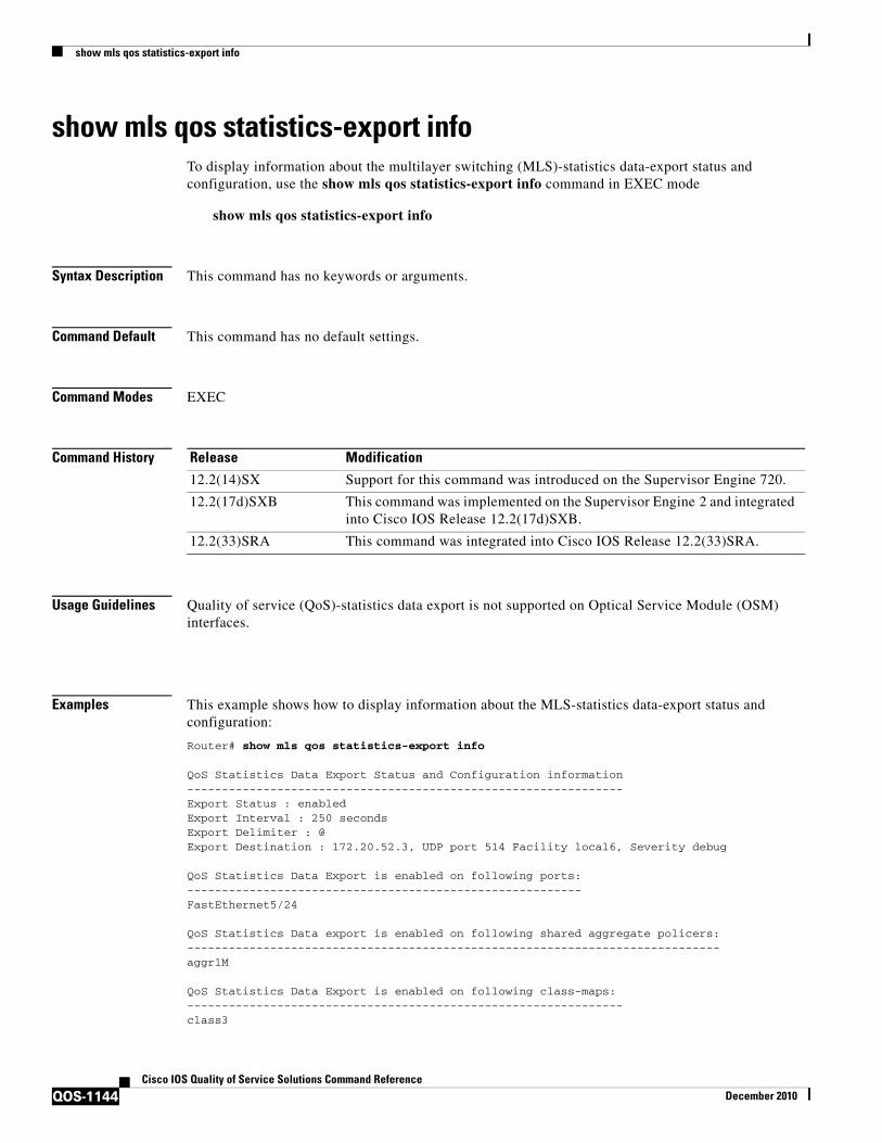
show mls qos statistics-export infoTo display information about the multilayer switching (MLS)-statistics data-export status and configuration, use the show mls qos statistics-export info command in EXEC mode
show mls qos statistics-export info
Syntax Description This command has no keywords or arguments.
Command Default This command has no default settings.
Command Modes EXEC
Command History
Usage Guidelines Quality of service (QoS)-statistics data export is not supported on Optical Service Module (OSM) interfaces.
Examples This example shows how to display information about the MLS-statistics data-export status and configuration:
Router# show mls qos statistics-export info
QoS Statistics Data Export Status and Configuration information---------------------------------------------------------------Export Status : enabledExport Interval : 250 secondsExport Delimiter : @Export Destination : 172.20.52.3, UDP port 514 Facility local6, Severity debug QoS Statistics Data Export is enabled on following ports:---------------------------------------------------------FastEthernet5/24 QoS Statistics Data export is enabled on following shared aggregate policers:-----------------------------------------------------------------------------aggr1M QoS Statistics Data Export is enabled on following class-maps:---------------------------------------------------------------class3
Release Modification
12.2(14)SX Support for this command was introduced on the Supervisor Engine 720.
12.2(17d)SXB This command was implemented on the Supervisor Engine 2 and integrated into Cisco IOS Release 12.2(17d)SXB.
12.2(33)SRA This command was integrated into Cisco IOS Release 12.2(33)SRA.
show mls qos statistics-export info
QOS-1145Cisco IOS Quality of Service Solutions Command Reference
December 2010
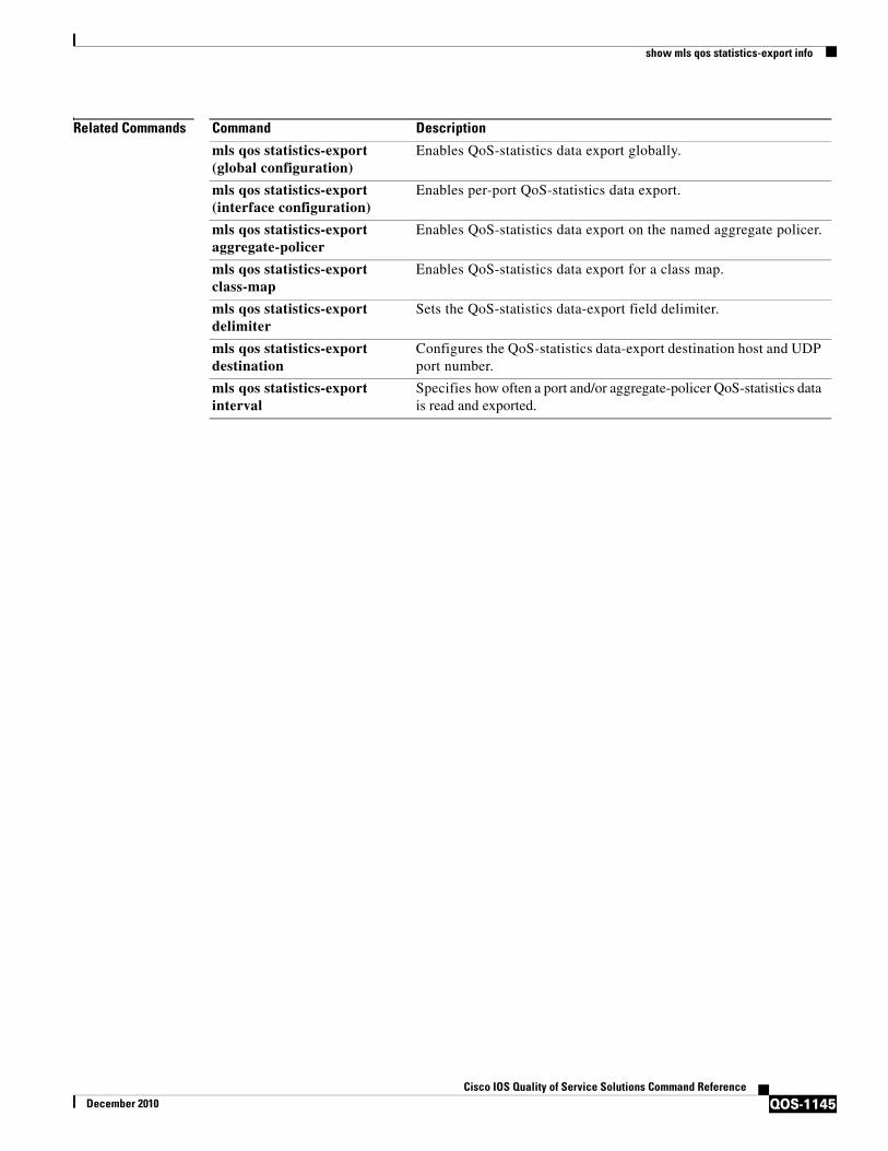
Related Commands Command Description
mls qos statistics-export (global configuration)
Enables QoS-statistics data export globally.
mls qos statistics-export (interface configuration)
Enables per-port QoS-statistics data export.
mls qos statistics-export aggregate-policer
Enables QoS-statistics data export on the named aggregate policer.
mls qos statistics-export class-map
Enables QoS-statistics data export for a class map.
mls qos statistics-export delimiter
Sets the QoS-statistics data-export field delimiter.
mls qos statistics-export destination
Configures the QoS-statistics data-export destination host and UDP port number.
mls qos statistics-export interval
Specifies how often a port and/or aggregate-policer QoS-statistics data is read and exported.

show platform hardware acl entry global-qos
QOS-1146Cisco IOS Quality of Service Solutions Command Reference
December 2010
show platform hardware acl entry global-qosTo display information about inbound and outbound access control list (ACL) ternary content addressable memory (TCAM) global Quality of Service (QoS) entries, use the show platform hardware acl entry global-qos command in privileged EXEC mode.
show platform hardware acl entry global-qos {in | out} {arp | ip | ipv6 | mac | mpls}[detail]
Syntax Description
Command Modes Privileged EXEC
Command History
Usage Guidelines Cisco IOS-based switches support the wire-rate ACL and QoS feature with use of the TCAM. Enabling ACLs and policies does not decrease the switching or routing performance of the switch as long as the ACLs are fully loaded in the TCAM.
To implement the various types of ACLs and QoS policies in hardware, the Cisco IOS-based switches use hardware lookup tables (TCAM) and various hardware registers in the Supervisor Engine. When a packet arrives, the switch performs a hardware table lookup (TCAM lookup) and decides to either permit or deny the packet.
Examples The following sample output from the show platform hardware acl entry global-qos command displays one result for inbound Address Resolution Protocol entries:
Switch# show platform hardware acl entry global-qos in arp
0x0000000000000003 arp ip any any mac any
The following sample output from the show platform hardware acl entry global-qos command displays the detailed results for inbound Address Resolution Protocol entries (the legend provides definitions for abbreviations that may appear in the output):
Switch# show platform hardware acl entry global-qos in arp detail
in Displays inbound entries in the output.
out Displays outbound entries in the output.
arp Specifies the Address Resolution Protocol for entries.
ip Specifies the Internet Protocol for entries.
ipv6 Specifies the Internet Protocol, Version 6 for entries.
mac Specifies the Media Access Control address for entries.
mpls Specifies the Multiprotocol Label Switching Protocol for entries.
detail (Optional) Displays detailed information about the entries.
Release Modification
12.2XJC This command was introduced.

show platform hardware acl entry global-qos
QOS-1147Cisco IOS Quality of Service Solutions Command Reference
December 2010
------------------------------------------------------------------------------------------
ENTRY TYPE: A - ARP I - IPv4 M - MPLS O - MAC Entry S - IPv6(Six) C - Compaction L - L2V4 Suffix: D - dynamic entry E - exception entry R - reserved entry
FIELDS: FS - first_seen/from_rp ACOS - acos/group_id F - ip_frag FF - frag_flag DPORT - dest_port SPORT - src_port LM - L2_miss GP - gpid_present ETYPE - enc_etype CEVLD - ce_vlan_valid MM - mpls_mcast FN - exp_from_null IV - ip_hdr_vld MV - mpls_valid E_CAU - exception_cause UK - U_key ACO - acos A/R - arp_rarp RR - req_repl GM - global_acl_fmt_match D-S-S-A - dest_mac_bcast, src_snd_mac_same, snd_tar_mac_same, arp_rarp_vld OM - ofe_mode SVLAN - Src_vlan
------------------------------------------------------------------------------------------
A INDEX LABEL A/R RR IP SA IP DA SRC MAC
D-S-S-A GM LM OM RSLT CNT
AR V 963 8191 1 7 0.0.0.0 0.0.0.0 FFFF.FFFF.FFFF
1-1-1-1 1 1 0 0x0000000000000003 0
AR M 963 0x0000 0 0x0 0.0.0.0 0.0.0.0 0000.0000.0000
0-0-0-1 0 0 1
Command Description
mls qos protocol Configures TCAM entries that are displayed by the show platform hardware acl entry global-qos command.

show platform hardware qfp active feature qos config global
QOS-1148Cisco IOS Quality of Service Solutions Command Reference
December 2010
show platform hardware qfp active feature qos config globalTo display whether the QoS: Packet Marking Statistics and QoS: Packet Matching Statistics features are currently enabled, use the show platform hardware qfp active feature qos config global command in privileged EXEC mode.
show platform hardware qfp active feature qos config global
Syntax Description
Command Default Disabled (no information about the status of the QoS: Packet Marking Statistics or QoS: Packet Matching Statistics feature is displayed).
Command Modes Privileged EXEC (#)
Command History
Usage Guidelines Both the QoS: Packet Marking Statistics and QoS: Packet Matching Statistics features are disabled by default. Use the show platform hardware qfp active feature qos config global command to display whether they are enabled.
Examples The following example shows how to see if the QoS: Packet Marking Statistics or QoS: Packet Matching Statistics feature is enabled:
Router# show platform hardware qfp active feature qos config global
Marker statistics are: enabledMatch per filter statistics are: enabled
hardware Hardware
qfp Quantum flow processor
active Active instance
feature Feature specific information
qos Quality of Service (QoS) information
config QoS config information
global Global configuration
Release Modification
Cisco IOS XE Release 3.3S
This command was introduced.

show platform hardware qfp active feature qos config global
QOS-1149Cisco IOS Quality of Service Solutions Command Reference
December 2010
Table 175 describes the significant fields shown in the display.
Related Commands
Table 175 show platform hardware qfp active feature qos config global Field Descriptions
Field Description
Marker statistics are: The status of the QoS: Packet Marking Statistics feature, enabled or disabled.
Match per filter statistics are: The status of the QoS: Packet Matching Statistics feature, enabled or disabled.
Command Description
platform qos marker-statistics
Displays the number of packets that have modified headers and have been classified into a category for local router processing.
platform qos match-statistics per-filter
Displays the display the number of packets and bytes matching a user-defined filter.
show platform lowq
QOS-1150Cisco IOS Quality of Service Solutions Command Reference
December 2010
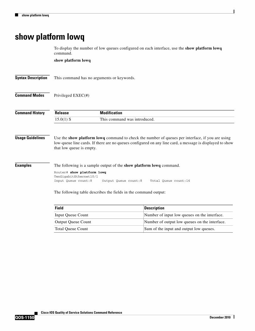
show platform lowq To display the number of low queues configured on each interface, use the show platform lowq command.
show platform lowq
Syntax Description This command has no arguments or keywords.
Command Modes Privileged EXEC(#)
Command History
Usage Guidelines Use the show platform lowq command to check the number of queues per interface, if you are using low-queue line cards. If there are no queues configured on any line card, a message is displayed to show that low queue is empty.
Examples The following is a sample output of the show platform lowq command.
Router# show platform lowqTenGigabitEthernet10/1Input Queue count:8 Output Queue count:8 Total Queue count:16
The following table describes the fields in the command output:
Release Modification
15.0(1) S This command was introduced.
Field Description
Input Queue Count Number of input low queues on the interface.
Output Queue Count Number of output low queues on the interface.
Total Queue Count Sum of the input and output low queues.

show platform qos policy-map
QOS-1151Cisco IOS Quality of Service Solutions Command Reference
December 2010
show platform qos policy-mapTo display the type and number of policy maps that are configured on the router, use the show platform qos policy-map command in privileged EXEC mode.
show platform qos policy-map
Syntax Description This command has no arguments or keywords.
Command Modes Privileged EXEC
Command History
Usage Guidelines On Cisco Catalyst 6500 series switches and Cisco 7600 series routers, you cannot attach a quality of service (QoS) policy map with match input vlan to an interface if you have already attached a QoS policy map to a VLAN interface (a logical interface that has been created with the interface vlan command). If you attempt to use both types of service policies, you must remove both types of service policies before you can add the policy maps.
The show platform qos policy-map command shows whether the router is currently configured for interface vlan and match input vlan service policies. It also shows the number of policy maps for each type.
Examples The following example shows a router that has service policies configured only on VLAN interfaces:
Router# show platform qos policy-map
service policy configured on int vlan: TRUE # of int vlan service policy instances: 3 match input vlan service policy configured: FALSE # of match input vlan service policy instances: 0
The following example shows a router that has service policies configured on VLAN interfaces and that has a service policy configured with match input vlan. In this configuration, you must remove all service policies from their interfaces, and then configure only one type or another.
Router# show platform qos policy-map
service policy configured on int vlan: TRUE # of int vlan service policy instances: 1 match input vlan service policy configured: TRUE # of match input vlan service policy instances: 1
Release Modification
12.2(18)SXE This command was introduced for Cisco Catalyst 6500 series switches and Cisco 7600 series routers.
12.2(33)SRA This command was integrated into Cisco IOS Release 12.2(33)SRA.
show platform qos policy-map
QOS-1152Cisco IOS Quality of Service Solutions Command Reference
December 2010
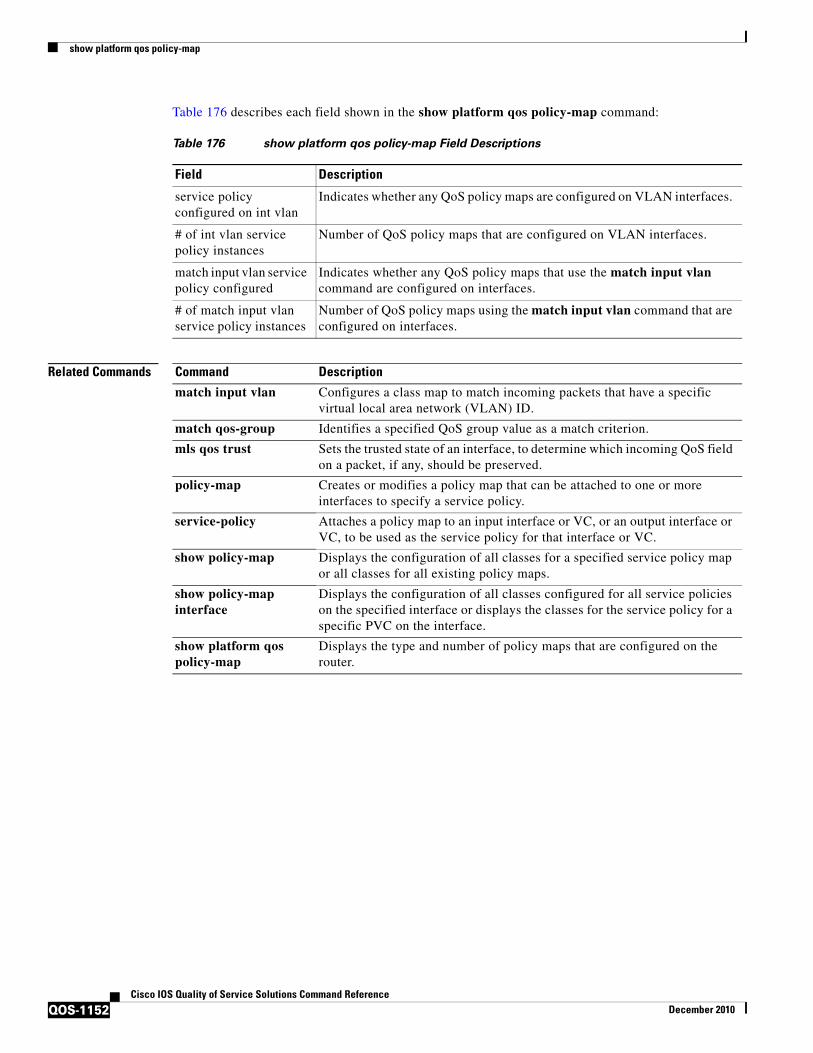
Table 176 describes each field shown in the show platform qos policy-map command:
Related Commands
Table 176 show platform qos policy-map Field Descriptions
Field Description
service policy configured on int vlan
Indicates whether any QoS policy maps are configured on VLAN interfaces.
# of int vlan service policy instances
Number of QoS policy maps that are configured on VLAN interfaces.
match input vlan service policy configured
Indicates whether any QoS policy maps that use the match input vlan command are configured on interfaces.
# of match input vlan service policy instances
Number of QoS policy maps using the match input vlan command that are configured on interfaces.
Command Description
match input vlan Configures a class map to match incoming packets that have a specific virtual local area network (VLAN) ID.
match qos-group Identifies a specified QoS group value as a match criterion.
mls qos trust Sets the trusted state of an interface, to determine which incoming QoS field on a packet, if any, should be preserved.
policy-map Creates or modifies a policy map that can be attached to one or more interfaces to specify a service policy.
service-policy Attaches a policy map to an input interface or VC, or an output interface or VC, to be used as the service policy for that interface or VC.
show policy-map Displays the configuration of all classes for a specified service policy map or all classes for all existing policy maps.
show policy-map interface
Displays the configuration of all classes configured for all service policies on the specified interface or displays the classes for the service policy for a specific PVC on the interface.
show platform qos policy-map
Displays the type and number of policy maps that are configured on the router.

show policy-manager events
QOS-1153Cisco IOS Quality of Service Solutions Command Reference
December 2010
show policy-manager eventsTo display detailed information about the policy-manager event statistics, use the show policy-manager events command in privileged EXEC mode.
show policy-manager events
Syntax Description This command has no arguments or keywords.
Command Modes Privileged EXEC (#)
Command History
Examples The following is sample output from the show policy-manager events command:
Router# show policy-manager events
Event Statistics0 catastrophic0 critical0 high0 medium0 low0 positive
The following events were discarded0 unknown
Event buffer poolNumber of free event buffers = 300Number of events awaiting processing by Policy Manager process = 0
Table 177 describes the significant fields shown in the display.
Release Modification
12.4(1) This command was introduced.
12.2(33)SRA This command was integrated into Cisco IOS Release 12.2(33)SRA.
12.2(33)SXH This command was integrated into Cisco IOS Release 12.2(33)SXH.
Cisco IOS XE Release 2.1
This command was implemented on the Cisco ASR 1000 series routers.
Table 177 show policy-manager events Field Descriptions
Field Description
catastrophic Displays the total number of events in a catastrophic state.
critical Displays the total number of events in a critical state.
high Displays the total number of events in a high severity state.
medium Displays the total number of events in a medium severity state.

show policy-manager events
QOS-1154Cisco IOS Quality of Service Solutions Command Reference
December 2010
Related Commands
low Displays the total number of events in a low severity state.
positive Displays the total number of events that are safe.
Number of free event buffers Displays the total number of event buffers that are free.
Number of events awaiting processing by Policy Manager process
Displays the number of events that are yet to be processed by the policy manager.
Table 177 show policy-manager events Field Descriptions (continued)
Field Description
Command Description
show policy-manager policy
Displays different policies of the policy manager.
show policy-manager subsystem
Displays subsystems of the policy manager.

show policy-manager policy
QOS-1155Cisco IOS Quality of Service Solutions Command Reference
December 2010
show policy-manager policyTo display information about the policy-manager policy database, use the show policy-manager policy command in privileged EXEC mode.
Cisco IOS SX, T, and XE Trains
show policy-manager policy [policy-id | detail | subsystem subsystem-name [detail | policy-name name]]
Cisco IOS SR Train
show policy-manager policy [policy-id | detail | event-id | policy-id | subsystem subsystem-name [detail | policy-name name]]
Syntax Description
Command Default If no argument or keywords are specified, information about all policies is displayed.
Command Modes Privileged EXEC (#)
Command History
policy-id (Optional) Displays information about the policy with the specified policy ID. The range is from 1 to 4294967295.
detail (Optional) Displays policy database information in detail.
subsystem (Optional) Displays information about the specified subsystem.
subsystem-name (Optional) Name of the subsystem.
policy-name (Optional) Displays information about the specified policy.
name (Optional) Name of the policy.
event-id (Optional) Displays information about the event ID table.
policy-id (Optional) Displays information about the policy ID table.
Release Modification
12.4(24)T This command was introduced in a release earlier than Cisco IOS Release 12.4(24)T.
12.2(33)SRC This command was modified and integrated into a release earlier than Cisco IOS Release 12.2(33)SRC. The event-id and policy-id keywords were added.
12.2(33)SXI This command was integrated into a release earlier than Cisco IOS Release 12.2(33)SXI.
Cisco IOS XE Release 2.1
This command was integrated into Cisco IOS XE Release 2.1.

show policy-manager policy
QOS-1156Cisco IOS Quality of Service Solutions Command Reference
December 2010
Examples The following is sample output from the show policy-manager policy command. The field descriptions are self-explanatory.
Router# show policy-manager policy
Status (S) codes:A = activeD = deactivated
S ID Subsystem Name
Related Commands Command Description
show policy-manager events
Displays detailed information about the policy-manager event statistics.
show policy-manager subsystem
Displays subsystems of the policy manager.

show policy-map
QOS-1157Cisco IOS Quality of Service Solutions Command Reference
December 2010
show policy-mapTo display the configuration of all classes for a specified service policy map or of all classes for all existing policy maps, use the show policy-map command in user EXEC or privileged EXEC mode.
show policy-map [policy-map]
Syntax Description
Command Default All existing policy map configurations are displayed.
Command Modes User EXEC (>)Privileged EXEC (#)
Command History
policy-map (Optional) Name of the service policy map whose complete configuration is to be displayed. The name can be a maximum of 40 characters.
Release Modification
12.0(5)T This command was introduced.
12.0(5)XE This command was integrated into Cisco IOS Release 12.0(5)XE.
12.0(7)S This command was intergrated into Cisco IOS Release 12.0(7)S.
12.1(1)E This command was integrated into Cisco IOS Release 12.1(1)E.
12.2(4)T This command was modified for two-rate traffic policing to display burst parameters and associated actions.
12.2(8)T The command was modified for the Policer Enhancement—Multiple Actions feature and the Weighted Random Early Detection (WRED)—Explicit Congestion Notification (ECN) feature.
12.2(13)T The following modifications were made:
• The output was modified for the Percentage-Based Policing and Shaping feature.
• This command was modified as part of the Modular QoS CLI (MQC) Unconditional Packet Discard feature. Traffic classes can now be configured to discard packets belonging to a specified class.
• This command was modified for the Enhanced Packet Marking feature. A mapping table (table map) can now be used to convert and propagate packet-marking values.
12.2(15)T This command was modified to support display of Frame Relay voice-adaptive traffic-shaping information.
12.0(28)S The output of this command was modified for the QoS: Percentage-Based Policing feature to display the committed (conform) burst (bc) and excess (peak) burst (be) sizes in milliseconds (ms).
12.2(14)SX Support for this command was introduced on the Supervisor Engine 720.
12.2(17d)SXB This command was implemented on the Supervisor Engine 2 and integrated into Cisco IOS Release 12.2(17d)SXB.

show policy-map
QOS-1158Cisco IOS Quality of Service Solutions Command Reference
December 2010
Usage Guidelines The show policy-map command displays the configuration of a policy map created using the policy-map command. You can use the show policy-map command to display all class configurations comprising any existing service policy map, whether or not that policy map has been attached to an interface. The command displays:
• ECN marking information only if ECN is enabled on the interface.
• Bandwidth-remaining ratio configuration and statistical information, if configured and used to determine the amount of unused (excess) bandwidth to allocate to a class queue during periods of congestion.
Cisco 10000 Series Router
In Cisco IOS Release 12.2(33)SB, the output of the show policy-map command is slightly different from previous releases when the policy is a hierarchical policy.
For example, in Cisco IOS Release 12.2(33)SB output similar to the following displays when you specify a hierarchical policy in the show policy-map command:
Router# show policy-map Bronze
policy-map bronzeclass class-defaultshape average 34386000service-policy Child
In Cisco IOS Release 12.2(31)SB, output similar to the following displays when you specify a hierarchical policy in the show policy-map command:
Router# show policy-map Gold
12.2(28)SB This command was integrated into Cisco IOS Release 12.2(28)SB, and the command was modified to display information about Layer 2 Tunnel Protocol Version 3 (L2TPv3) tunnel marking.
12.2(31)SB2 This command was enhanced to display bandwidth-remaining ratios configured on traffic classes and ATM overhead accounting, and was implemented on the Cisco 10000 series router for the PRE3.
12.2(33)SRA This command was integrated into Cisco IOS Release 12.2(33)SRA.
12.2(33)SRC Support for the Cisco 7600 series router was added.
12.4(15)T2 This command was modified to display information about Generic Routing Encapsulation (GRE) tunnel marking.
Note For this release, GRE-tunnel marking is supported on the Cisco MGX Route Processor Module (RPM-XF) platform only.
12.2(33)SB This command was modified to display information about GRE-tunnel marking, and support for the Cisco 7300 series router was added. This command’s output was modified on the Cisco 10000 series router for the PRE3 and PRE4.
Cisco IOS XE 2.1 This command was integrated into Cisco IOS XE Release 2.1 and was implemented on the Cisco ASR 1000 series router.
12.4(20)T This command was modified. Support was added for hierarchical queueing framework (HQF) using the Modular Quality of Service (QoS) Command-Line Interface (CLI) (MQC).
Release Modification

show policy-map
QOS-1159Cisco IOS Quality of Service Solutions Command Reference
December 2010
policy-map GoldClass class-defaultAverage Rate Traffic Shapingcir 34386000 (bps)service-policy Child2
In Cisco IOS Release 12.2(33)SB, the output from the show policy-map command displays police actions on separate lines as shown in the following sample output:
Router# show policy-map Premium
Policy Map PremiumClass P1prioritypolice percent 50 25 ms 0 msconform-action transmitexceed-action transmitviolate-action drop
In Cisco IOS Release 12.2(31)SB, the output from the show policy-map command displays police actions on one line as shown in the following sample output:
Router# show policy-map Premium
Policy Map PremiumClass P2prioritypolice percent 50 25 ms 0 ms conform-action transmit exceed-action transmit violate-
action drop
Examples This section provides sample output from typical show policy-map commands. Depending upon the interface or platform in use and the options enabled (for example, Weighted Fair Queueing [WFQ]), the output you see may vary slightly from the ones shown below.
• Weighted Fair Queueing: Example, page 1160
• Frame Relay Voice-Adaptive Traffic-Shaping: Example, page 1161
• Traffic Policing: Example, page 1162
• Two-Rate Traffic Policing: Example, page 1162
• Multiple Traffic Policing Actions: Example, page 1163
• Explicit Congestion Notification: Example, page 1164
• Modular QoS CLI (MQC) Unconditional Packet Discard: Example, page 1165
• Percentage-Based Policing and Shaping: Example, page 1165
• Enhanced Packet Marking: Example, page 1167
• Bandwidth-Remaining Ratio: Example, page 1167
• ATM Overhead Accounting: Example, page 1168
• Tunnel Marking: Example, page 1168
• HQF: Example 1, page 1169
• HQF: Example 2, page 1169

show policy-map
QOS-1160Cisco IOS Quality of Service Solutions Command Reference
December 2010
Weighted Fair Queueing: Example
The following example displays the contents of the service policy map called po1. In this example, WFQ is enabled.
Router# show policy-map po1
Policy Map po1 Weighted Fair Queueing Class class1 Bandwidth 937 (kbps) Max thresh 64 (packets) Class class2 Bandwidth 937 (kbps) Max thresh 64 (packets) Class class3 Bandwidth 937 (kbps) Max thresh 64 (packets) Class class4 Bandwidth 937 (kbps) Max thresh 64 (packets) Class class5 Bandwidth 937 (kbps) Max thresh 64 (packets) Class class6 Bandwidth 937 (kbps) Max thresh 64 (packets) Class class7 Bandwidth 937 (kbps) Max thresh 64 (packets) Class class8 Bandwidth 937 (kbps) Max thresh 64 (packets)
The following example displays the contents of all policy maps on the router. Again, WFQ is enabled.
Router# show policy-map
Policy Map poH1 Weighted Fair Queueing Class class1 Bandwidth 937 (kbps) Max thresh 64 (packets) Class class2 Bandwidth 937 (kbps) Max thresh 64 (packets) Class class3 Bandwidth 937 (kbps) Max thresh 64 (packets) Class class4 Bandwidth 937 (kbps) Max thresh 64 (packets) Class class5 Bandwidth 937 (kbps) Max thresh 64 (packets) Class class6 Bandwidth 937 (kbps) Max thresh 64 (packets) Class class7Bandwidth 937 (kbps) Max thresh 64 (packets) Class class8 Bandwidth 937 (kbps) Max thresh 64 (packets)Policy Map policy2 Weighted Fair Queueing Class class1 Bandwidth 300 (kbps) Max thresh 64 (packets) Class class2 Bandwidth 300 (kbps) Max thresh 64 (packets) Class class3 Bandwidth 300 (kbps) Max thresh 64 (packets) Class class4 Bandwidth 300 (kbps) Max thresh 64 (packets) Class class5 Bandwidth 300 (kbps) Max thresh 64 (packets) Class class6 Bandwidth 300 (kbps) Max thresh 64 (packets)

show policy-map
QOS-1161Cisco IOS Quality of Service Solutions Command Reference
December 2010
Table 178 describes the significant fields shown in the display.
Frame Relay Voice-Adaptive Traffic-Shaping: Example
The following sample output for the show-policy map command indicates that Frame Relay voice-adaptive traffic-shaping is configured in the class-default class in the policy map MQC-SHAPE-LLQ1 and that the deactivation timer is set to 30 seconds.
Router# show policy-map
Policy Map VSD1 Class VOICE1 Strict Priority Bandwidth 10 (kbps) Burst 250 (Bytes) Class SIGNALS1 Bandwidth 8 (kbps) Max Threshold 64 (packets)
Class DATA1 Bandwidth 15 (kbps) Max Threshold 64 (packets)
Policy Map MQC-SHAPE-LLQ1 Class class-default Traffic Shaping Average Rate Traffic Shaping CIR 63000 (bps) Max. Buffers Limit 1000 (Packets) Adapt to 8000 (bps) Voice Adapt Deactivation Timer 30 Sec service-policy VSD1
Note In Cisco IOS Release 12.4(20)T, if an interface configured with a policy map is full of heavy traffic, the implicit policer allows the traffic as defined in the bandwidth statement of each traffic class.
Table 179 describes the significant fields shown in the display.
Table 178 show policy-map Field Descriptions—Configured for WFQ
Field Description
Policy Map Policy map name.
Class Class name.
Bandwidth Amount of bandwidth in kbps allocated to class.
Max thresh Maximum threshold in number of packets.
Table 179 show policy-map Field Descriptions—Configured for Frame Relay Voice-Adaptive
Traffic-Shaping
Field Description
Strict Priority Indicates the queueing priority assigned to the traffic in this class.
Burst Specifies the traffic burst size in bytes.
Traffic Shaping Indicates that Traffic Shaping is enabled.
Average Rate Traffic Shaping Indicates the type of Traffic Shaping enabled. Choices are Peak Rate Traffic Shaping or Average Rate Traffic Shaping.
CIR Committed Information Rate (CIR) in bps.
Max. Buffers Limit Maximum memory buffer size in packets.

show policy-map
QOS-1162Cisco IOS Quality of Service Solutions Command Reference
December 2010
Traffic Policing: Example
The following is sample output from the show policy-map command. This sample output displays the contents of a policy map called policy1. In policy 1, traffic policing on the basis of a committed information rate (CIR) of 20 percent has been configured, and the bc and be have been specified in milliseconds. As part of the traffic policing configuration, optional conform, exceed, and violate actions have been specified.
Router# show policy-map policy1
Policy Map policy1 Class class1 police cir percent 20 bc 300 ms pir percent 40 be 400 ms conform-action transmit exceed-action drop violate-action drop
Table 180 describes the significant fields shown in the display.
Two-Rate Traffic Policing: Example
The following is sample output from the show policy-map command when two-rate traffic policing has been configured. As shown below, two-rate traffic policing has been configured for a class called police. In turn, the class called police has been configured in a policy map called policy1. Two-rate traffic policing has been configured to limit traffic to an average committed rate of 500 kbps and a peak rate of 1 Mbps.
Router(config)# class-map policeRouter(config-cmap)# match access-group 101Router(config-cmap)# policy-map policy1Router(config-pmap)# class policeRouter(config-pmap-c)# police cir 500000 bc 10000 pir 1000000 be 10000 conform-actiontransmit exceed-action set-prec-transmit 2 violate-action dropRouter(config-pmap-c)# interface serial3/0Router(config-pmap-c)# exitRouter(config-pmap)# exit
Adapt to Traffic rate when shaping is active.
Voice Adapt Deactivation Timer Indicates that Frame Relay voice-adaptive traffic-shaping is configured, and that the deactivation timer is set to 30 seconds.
service-policy Name of the service policy configured in the policy map “MQC-SHAPE-LLQ1”.
Table 179 show policy-map Field Descriptions—Configured for Frame Relay Voice-Adaptive
Traffic-Shaping (continued)
Field Description
Table 180 show policy-map Field Descriptions—Configured for Traffic Policing
Field Description
Policy Map Name of policy map displayed.
Class Name of the class configured in the policy map displayed.
police Indicates that traffic policing on the basis of specified percentage of bandwidth has been enabled. The committed burst (Bc) and excess burst (Be) sizes have been specified in milliseconds (ms), and optional conform, exceed, and violate actions have been specified.

show policy-map
QOS-1163Cisco IOS Quality of Service Solutions Command Reference
December 2010
Router(config)# interface serial3/0Router(config-if)# service-policy output policy1Router(config-if)# end
The following sample output shows the contents of the policy map called policy1 :
Router# show policy-map policy1
Policy Map policy1Class policepolice cir 500000 conform-burst 10000 pir 1000000 peak-burst 10000 conform-actiontransmit exceed-action set-prec-transmit 2 violate-action drop
Traffic marked as conforming to the average committed rate (500 kbps) will be sent as is. Traffic marked as exceeding 500 kbps, but not exceeding 1 Mbps, will be marked with IP Precedence 2 and then sent. All traffic exceeding 1 Mbps will be dropped. The burst parameters are set to 10000 bytes.
Table 181 describes the significant fields shown in the display.
Multiple Traffic Policing Actions: Example
The following is sample output from the show policy-map command when the Policer Enhancement—Multiple Actions feature has been configured. The following sample output from the show policy-map command displays the configuration for a service policy called police. In this service policy, traffic policing has been configured to allow multiple actions for packets marked as conforming to, exceeding, or violating the CIR or the PIR shown in the example.
Router# show policy-map police
Policy Map police Class class-default police cir 1000000 bc 31250 pir 2000000 be 31250 conform-action transmit exceed-action set-prec-transmit 4 exceed-action set-frde-transmit
violate-action set-prec-transmit 2 violate-action set-frde-transmit
Packets conforming to the specified CIR (1000000 bps) are marked as conforming packets. These are transmitted unaltered.
Packets exceeding the specified CIR (but not the specified PIR, 2000000 bps) are marked as exceeding packets. For these packets, the IP Precedence level is set to 4, the discard eligibility (DE) bit is set to 1, and the packet is transmitted.
Packets exceeding the specified PIR are marked as violating packets. For these packets, the IP Precedence level is set to 2, the DE bit is set to 1, and the packet is transmitted.
Table 181 show policy-map Field Descriptions—Configured for Two-Rate Traffic Policing
Field Description
police Indicates that the police command has been configured to enable traffic policing. Also, displays the specified CIR, conform burst size (bc), peak information rate (PIR), and peak burst (BE) size used for marking packets.
conform-action Displays the action to be taken on packets conforming to a specified rate.
exceed-action Displays the action to be taken on packets exceeding a specified rate.
violate-action Displays the action to be taken on packets violating a specified rate.

show policy-map
QOS-1164Cisco IOS Quality of Service Solutions Command Reference
December 2010
Note Actions are specified by using the action argument of the police command. For more information about the available actions, see the police command reference page.
Table 182 describes the significant fields shown in the display.
Explicit Congestion Notification: Example
The following is sample output from the show policy-map command when the WRED—Explicit Congestion Notification (ECN) feature has been configured. The words “explicit congestion notification” (along with the ECN marking information) included in the output indicate that ECN has been enabled.
Router# show policy-map
Policy Map pol1 Class class-default Weighted Fair Queueing Bandwidth 70 (%) exponential weight 9 explicit congestion notification class min-threshold max-threshold mark-probability ---------------------------------------------------------- ---------------------------------------------------------- 0 - - 1/10
1 - - 1/10 2 - - 1/10 3 - - 1/10 4 - - 1/10 5 - - 1/10 6 - - 1/10 7 - - 1/10 rsvp - - 1/10
Table 182 show policy-map Field Descriptions—Configured for Multiple Traffic Policing Actions
Field Description
police Indicates that the police command has been configured to enable traffic policing. Also, displays the specified CIR, BC, PIR, and BE used for marking packets.
conform-action Displays the one or more actions to be taken on packets conforming to a specified rate.
exceed-action Displays the one or more actions to be taken on packets exceeding a specified rate.
violate-action Displays the one or more actions to be taken on packets violating a specified rate.
show policy-map
QOS-1165Cisco IOS Quality of Service Solutions Command Reference
December 2010
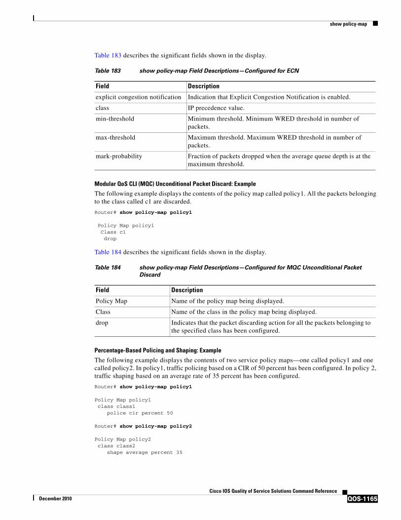
Table 183 describes the significant fields shown in the display.
Modular QoS CLI (MQC) Unconditional Packet Discard: Example
The following example displays the contents of the policy map called policy1. All the packets belonging to the class called c1 are discarded.
Router# show policy-map policy1
Policy Map policy1 Class c1 drop
Table 184 describes the significant fields shown in the display.
Percentage-Based Policing and Shaping: Example
The following example displays the contents of two service policy maps—one called policy1 and one called policy2. In policy1, traffic policing based on a CIR of 50 percent has been configured. In policy 2, traffic shaping based on an average rate of 35 percent has been configured.
Router# show policy-map policy1
Policy Map policy1 class class1 police cir percent 50
Router# show policy-map policy2
Policy Map policy2 class class2 shape average percent 35
Table 183 show policy-map Field Descriptions—Configured for ECN
Field Description
explicit congestion notification Indication that Explicit Congestion Notification is enabled.
class IP precedence value.
min-threshold Minimum threshold. Minimum WRED threshold in number of packets.
max-threshold Maximum threshold. Maximum WRED threshold in number of packets.
mark-probability Fraction of packets dropped when the average queue depth is at the maximum threshold.
Table 184 show policy-map Field Descriptions—Configured for MQC Unconditional Packet
Discard
Field Description
Policy Map Name of the policy map being displayed.
Class Name of the class in the policy map being displayed.
drop Indicates that the packet discarding action for all the packets belonging to the specified class has been configured.
show policy-map
QOS-1166Cisco IOS Quality of Service Solutions Command Reference
December 2010
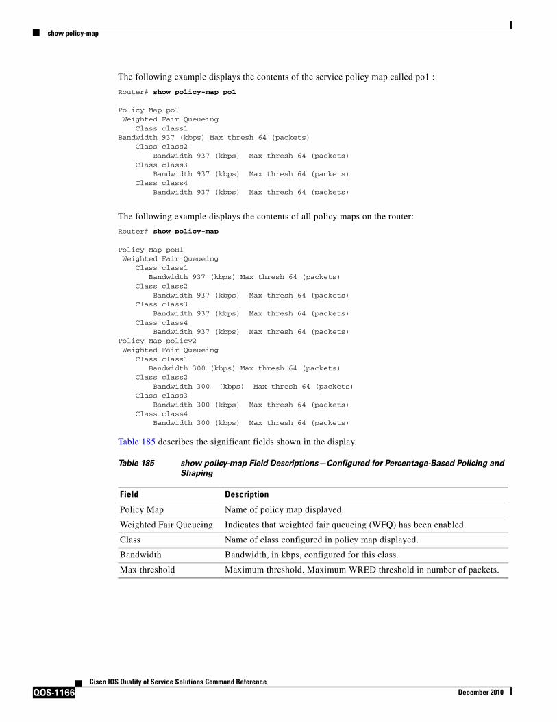
The following example displays the contents of the service policy map called po1 :
Router# show policy-map po1
Policy Map po1 Weighted Fair Queueing Class class1Bandwidth 937 (kbps) Max thresh 64 (packets) Class class2 Bandwidth 937 (kbps) Max thresh 64 (packets) Class class3 Bandwidth 937 (kbps) Max thresh 64 (packets) Class class4 Bandwidth 937 (kbps) Max thresh 64 (packets)
The following example displays the contents of all policy maps on the router:
Router# show policy-map
Policy Map poH1 Weighted Fair Queueing Class class1 Bandwidth 937 (kbps) Max thresh 64 (packets) Class class2 Bandwidth 937 (kbps) Max thresh 64 (packets) Class class3 Bandwidth 937 (kbps) Max thresh 64 (packets) Class class4 Bandwidth 937 (kbps) Max thresh 64 (packets)Policy Map policy2 Weighted Fair Queueing Class class1 Bandwidth 300 (kbps) Max thresh 64 (packets) Class class2 Bandwidth 300 (kbps) Max thresh 64 (packets) Class class3 Bandwidth 300 (kbps) Max thresh 64 (packets) Class class4 Bandwidth 300 (kbps) Max thresh 64 (packets)
Table 185 describes the significant fields shown in the display.
Table 185 show policy-map Field Descriptions—Configured for Percentage-Based Policing and
Shaping
Field Description
Policy Map Name of policy map displayed.
Weighted Fair Queueing Indicates that weighted fair queueing (WFQ) has been enabled.
Class Name of class configured in policy map displayed.
Bandwidth Bandwidth, in kbps, configured for this class.
Max threshold Maximum threshold. Maximum WRED threshold in number of packets.

show policy-map
QOS-1167Cisco IOS Quality of Service Solutions Command Reference
December 2010
Enhanced Packet Marking: Example
The following sample output from the show policy-map command displays the configuration for policy maps called policy1 and policy2.
In policy1 , a table map called table-map-cos1 has been configured to determine the precedence based on the class of service (CoS) value. Policy map policy 1 converts and propagates the packet markings defined in the table map called table-map-cos1.
The following sample output from the show policy-map command displays the configuration for service polices called policy1 and policy2 . In policy1 , a table map called table-map1 has been configured to determine the precedence according to the CoS value. In policy2 , a table map called table-map2 has been configured to determine the CoS value according to the precedence value.
Router# show policy-map policy1
Policy Map policy1 Class class-default set precedence cos table table-map1
Router# show policy-map policy2
Policy Map policy2 Class class-default set cos precedence table table-map2
Table 186 describes the fields shown in the display.
Bandwidth-Remaining Ratio: Example
The following sample output for the show policy-map command indicates that the class-default class of the policy map named vlan10_policy has a bandwidth-remaining ratio of 10. When congestion occurs, the scheduler allocates class-default traffic 10 times the unused bandwidth allocated in relation to other subinterfaces.
Router# show policy-map vlan10_policy
Policy Map vlan10_policy Class class-default Average Rate Traffic Shaping cir 1000000 (bps) bandwidth remaining ratio 10 service-policy child_policy
Table 186 show policy-map Field Descriptions—Configured for Enhanced Packet Marking
Field Description
Policy Map Name of the policy map being displayed.
Class Name of the class in the policy map being displayed.
set precedence cos table table-map1
or
set cos precedence table table-map2
Name of the set command used to set the specified value.
For instance, set precedence cos table-map1 indicates that a table map called table-map1 has been configured to set the precedence value on the basis of the values defined in the table map.
Alternately, set cos table table-map2 indicates that a table map called table-map2 has been configured to set the CoS value on the basis of the values defined in the table map.

show policy-map
QOS-1168Cisco IOS Quality of Service Solutions Command Reference
December 2010
Table 187 describes the fields shown in the display.
ATM Overhead Accounting: Example
The following sample output for the show policy-map command indicates that ATM overhead accounting is enabled for the class-default class. The BRAS-DSLAM encapsulation is dot1q and the subscriber encapsulation is snap-rbe for the AAL5 service.
Policy Map unit-testClass class-default
Average Rate Traffic Shapingcir 10% account dot1q aal5 snap-rbe
Table 188 describes the significant fields shown in the display.
Tunnel Marking: Example
In this sample output of the show policy-map command, the character string “ip precedence tunnel 4” indicates that tunnel marking (either L2TPv3 or GRE) has been configured to set the IP precedence value to 4 in the header of a tunneled packet.
Note In Cisco IOS Release 12.4(15)T2, GRE-tunnel marking is supported on the RPM-XF platform only.
Router# show policy-map
Policy Map TUNNEL_MARKING Class MATCH_FRDE set ip precedence tunnel 4
Table 187 show policy-map Field Descriptions—Configured for Bandwidth-Remaining Ratio
Field Description
Policy Map Name of the policy map being displayed.
Class Name of the class in the policy map being displayed.
Average Rate Traffic Shaping Indicates that Average Rate Traffic Shaping is configured.
cir Committed information rate (CIR) used to shape traffic.
bandwidth remaining ratio Indicates the ratio used to allocate excess bandwidth.
Table 188 show policy-map Field Descriptions—Configured for ATM Overhead Accounting
Field Description
Average Rate Committed burst (Bc) is the maximum number of bits sent out in each interval.
cir 10% Committed information rate (CIR) is 10 percent of the available interface bandwidth.
dot1q BRAS-DSLAM encapsulation is 802.1Q VLAN.
aal5 DSLAM-CPE encapsulation type is based on the ATM Adaptation Layer 5 service. AAL5 supports connection-oriented variable bit rate (VBR) services.
snap-rbe Subscriber encapsulation type.

show policy-map
QOS-1169Cisco IOS Quality of Service Solutions Command Reference
December 2010
Table 189 describes the fields shown in the display.
HQF: Example 1
The following sample output from the show policy-map command displays the configuration for a policy map called test1:
Router# show policy-map test1
Policy Map test1 Class class-default Average Rate Traffic Shaping cir 1536000 (bps) service-policy test2
Table 190 describes the fields shown in the display.
HQF: Example 2
The following sample output from the show policy-map command displays the configuration for a policy map called test2:
Router# show policy-map test2
Policy Map test2 Class RT priority 20 (%) Class BH bandwidth 40 (%) queue-limit 128 packets Class BL bandwidth 35 (%) packet-based wred, exponential weight 9 dscp min-threshold max-threshold mark-probablity ---------------------------------------------------------- af21 (18) 100 400 1/10 default (0) - - 1/10
Table 189 show policy-map Field Descriptions—Configured for Tunnel Marking
Field Description
Policy Map Name of the policy map being displayed.
Class Name of the class in the policy map being displayed.
set ip precedence tunnel Indicates that tunnel marking has been configured.
Table 190 show policy-map Field Descriptions—Configured for HQF
Field Description
Policy Map Name of the policy map being displayed.
Class Name of the class in the policy map being displayed.
Average Rate Traffic Shaping Indicates that Average Rate Traffic Shaping is configured.
cir Committed information rate (CIR) in bps.
service-policy Name of the service policy configured in policy map “test1”.

show policy-map
QOS-1170Cisco IOS Quality of Service Solutions Command Reference
December 2010
Table 191 describes the fields shown in the display.
Related Commands
Table 191 show policy-map Field Descriptions—Configured for HQF
Field Description
Policy Map Name of the policy map being displayed.
Class Name of the class in the policy map being displayed.
Average Rate Traffic Shaping Indicates that Average Rate Traffic Shaping is configured.
priority Indicates the queueing priority percentage assigned to traffic in this class.
bandwidth Indicates the bandwidth percentage allocated to traffic in this class.
queue-limit Indicates the queue limit in packets for this traffic class.
packet-based wred, exponential weight
Indicates that random detect is being applied and the units used are packets. Exponential weight is a factor for calculating the average queue size used with WRED.
dscp Differentiated services code point (DSCP). Values can be the following:
• 0 to 63—Numerical DSCP values. The default value is 0.
• af1 to af43—Assured forwarding (AF) DSCP values.
• cs1 to cs7—Type of service (ToS) precedence values.
• default—Default DSCP value.
• ef—Expedited forwarding (EF) DSCP values.
min-threshold Minimum threshold. Minimum WRED threshold in number of packets.
max-threshold Maximum threshold. Maximum WRED threshold in number of packets.
mark-probability Fraction of packets dropped when the average queue depth is at the maximum threshold.
Command Description
bandwidth Specifies or modifies the bandwidth allocated for a class belonging to a policy map, and enables ATM overhead accounting.
bandwidth remaining ratio Specifies a bandwidth-remaining ratio for class queues and subinterface-level queues to determine the amount of unused (excess) bandwidth to allocate to the queue during congestion.
class (policy map) Specifies the name of the class whose policy you want to create or change, and the default class (commonly known as the class-default class) before you configure its policy.
class–map Creates a class map to be used for matching packets to a specified class.
drop Configures a traffic class to discard packets belonging to a specific class.
police Configures traffic policing.
police (two rates) Configures traffic policing using two rates, the CIR and the PIR.

show policy-map
QOS-1171Cisco IOS Quality of Service Solutions Command Reference
December 2010
policy-map Creates or modifies a policy map that can be attached to one or more interfaces to specify a service policy.
random-detect ecn Enables ECN.
shape Shapes traffic to the indicated bit rate according to the algorithm specified, and enables ATM overhead accounting.
show policy-map class Displays the configuration for the specified class of the specified policy map.
show policy-map interface Displays the packet statistics of all classes that are configured for all service policies either on the specified interface or subinterface or on a specific PVC on the interface.
show running-config Displays the current configuration of the router. If configured, the command output includes information about ATM overhead accounting.
show table-map Displays the configuration of a specified table map or of all table maps.
table-map (value mapping) Creates and configures a mapping table for mapping and converting one packet-marking value to another.
Command Description

show policy-map class
QOS-1172Cisco IOS Quality of Service Solutions Command Reference
December 2010
show policy-map classTo display the configuration for the specified class of the specified policy map, use the show policy-map class command in user EXEC or privileged EXEC mode.
show policy-map policy-map class class-name
Syntax Description
Command Modes User EXEC (>)Privileged EXEC (#)
Command History
Usage Guidelines You can use the show policy-map class command to display any single class configuration for any service policy map, whether or not the specified service policy map has been attached to an interface.
Examples The following example displays configurations for the class called class7 that belongs to the policy map called po1:
Router# show policy-map po1 class class7
Class class7 Bandwidth 937 (kbps) Max Thresh 64 (packets)
policy-map The name of a policy map that contains the class configuration to be displayed.
class-name The name of the class whose configuration is to be displayed.
Release Modification
12.0(5)T This command was introduced.
12.0(5)XE This command was integrated into Cisco IOS Release 12.0(5)XE.
12.0(7)S This command was integrated into Cisco IOS Release 12.0(7)S.
12.1(1)E This command was integrated into Cisco IOS Release 12.1(1)E.
12.2(33)SRA This command was integrated into Cisco IOS Release 12.2(33)SRA.
12.2SX This command is supported in the Cisco IOS Release 12.2SX train. Support in a specific 12.2SX release of this train depends on your feature set, platform, and platform hardware.
Cisco IOS XE Release 2.1
This command was implemented on Cisco ASR 1000 series routers.

show policy-map class
QOS-1173Cisco IOS Quality of Service Solutions Command Reference
December 2010
Related Commands Command Description
show policy-map Displays the configuration of all classes for a specified service policy map or all classes for all existing policy maps.
show policy-map interface
Displays the configuration of all classes configured for all service policies on the specified interface or displays the classes for the service policy for a specific PVC on the interface.

show policy-map control-plane
QOS-1174Cisco IOS Quality of Service Solutions Command Reference
December 2010
show policy-map control-planeTo display the configuration and statistics for a traffic class or all traffic classes in the policy maps attached to the control plane for aggregate or distributed control plane services, use the show policy-map control-plane command in privileged EXEC mode.
Cisco 3660, 3800, 7200, 7400, and 7500 Series Routers
show policy-map control-plane [type policy-type] [all | slot slot-number] [host | transit | cef-exception] [input [class class-name] | output [class class-name]]
Cisco 7600 and ASR 1000 Series Routers
show policy-map control-plane [all] [input [class class-name] | output [class class-name]]
Syntax Description
Command Default Information displays for all classes of the policy map of the control plane.
Command Modes Privileged EXEC (#)
Command History
type policy-type (Optional) Specifies policy-map type for which you want statistics (for example, port-filter or queue-threshold).
all (Optional) Displays all QoS control plane policies used in aggregate and distributed control plane (CP) services.
slot slot-number (Optional) Displays information about the quality of service (QoS) policy used to perform distributed CP services on the specified line card.
host (Optional) Displays policy-map and class-map statistics for the host subinterface.
transit (Optional) Displays policy-map and class-map statistics for the transit subinterface.
cef-exception (Optional) Displays policy-map and class-map statistics for the Cef-exception subinterface.
input (Optional) Displays statistics for the attached input policy.
output (Optional) Displays statistics for the attached output policy.
Note The output keyword is supported only in Cisco IOS Release 12.3(4)T and later Cisco IOS 12.3T releases.
class class-name (Optional) Name of the class whose configuration and statistics are to be displayed.
Release Modification
12.2(18)S This command was introduced.
12.3(4)T This command was integrated into Cisco IOS Release 12.3(4)T, and support for the output keyword was added.
12.0(29)S This command was integrated into Cisco IOS Release 12.0(29)S.

show policy-map control-plane
QOS-1175Cisco IOS Quality of Service Solutions Command Reference
December 2010
Usage Guidelines The show policy-map control-plane command displays information for aggregate and distributed control-plane policing services that manage the number or rate of control-plane (CP) packets sent to the process level of the route processor.
Information for distributed control-plane service is displayed for a specified line card. Distributed CP services are performed on a line card’s distributed switch engine and manage CP traffic sent from all interfaces on the line card to the route processor, where aggregate CP services (for CP packets received from all line cards on the router) are performed.
Examples The following example shows that the policy map TEST is associated with the control plane. This policy map polices traffic that matches the class map TEST, while allowing all other traffic (that matches the class map called “class-default”) to go through as is.
Router# show policy-map control-plane
Control Plane
Service-policy input:TEST
Class-map:TEST (match-all) 20 packets, 11280 bytes 5 minute offered rate 0 bps, drop rate 0 bps Match:access-group 101 police: 8000 bps, 1500 limit, 1500 extended limit conformed 15 packets, 6210 bytes; action:transmit exceeded 5 packets, 5070 bytes; action:drop violated 0 packets, 0 bytes; action:drop conformed 0 bps, exceed 0 bps, violate 0 bps
Class-map:class-default (match-any) 105325 packets, 11415151 bytes 5 minute offered rate 0 bps, drop rate 0 bps Match:any
Table 192 describes the significant fields shown in the display.
12.2(18)SXD1 This command was integrated into Cisco IOS Release 12.2(18)SXD1.
12.0(30)S The slot slot-number parameter was added to support distributed CP services.
12.4(4)T Support was added for the type policy-type keyword and argument combination and for the host, transit, and cef-exception keywords.
12.2(33)SRA This command was integrated into Cisco IOS Release 12.2(33)SRA.
Cisco IOS XE Release 2.2
This command was implemented on Cisco ASR 1000 series routers.
Release Modification
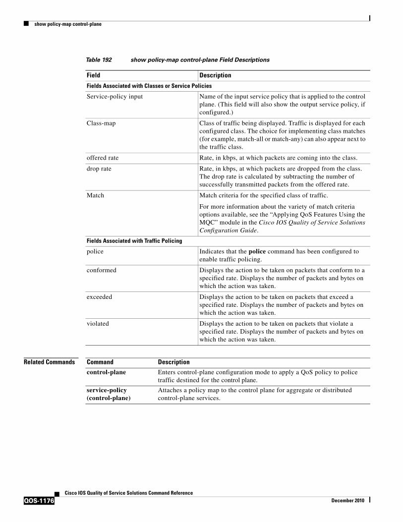
show policy-map control-plane
QOS-1176Cisco IOS Quality of Service Solutions Command Reference
December 2010
Related Commands
Table 192 show policy-map control-plane Field Descriptions
Field Description
Fields Associated with Classes or Service Policies
Service-policy input Name of the input service policy that is applied to the control plane. (This field will also show the output service policy, if configured.)
Class-map Class of traffic being displayed. Traffic is displayed for each configured class. The choice for implementing class matches (for example, match-all or match-any) can also appear next to the traffic class.
offered rate Rate, in kbps, at which packets are coming into the class.
drop rate Rate, in kbps, at which packets are dropped from the class. The drop rate is calculated by subtracting the number of successfully transmitted packets from the offered rate.
Match Match criteria for the specified class of traffic.
For more information about the variety of match criteria options available, see the “Applying QoS Features Using the MQC” module in the Cisco IOS Quality of Service Solutions Configuration Guide.
Fields Associated with Traffic Policing
police Indicates that the police command has been configured to enable traffic policing.
conformed Displays the action to be taken on packets that conform to a specified rate. Displays the number of packets and bytes on which the action was taken.
exceeded Displays the action to be taken on packets that exceed a specified rate. Displays the number of packets and bytes on which the action was taken.
violated Displays the action to be taken on packets that violate a specified rate. Displays the number of packets and bytes on which the action was taken.
Command Description
control-plane Enters control-plane configuration mode to apply a QoS policy to police traffic destined for the control plane.
service-policy (control-plane)
Attaches a policy map to the control plane for aggregate or distributed control-plane services.

show policy-map interface
QOS-1177Cisco IOS Quality of Service Solutions Command Reference
December 2010
show policy-map interfaceTo display the statistics and the configurations of the input and output policies that are attached to an interface, use the show policy-map interface command in user EXEC or privileged EXEC mode.
ATM Shared Port Adapters
show policy-map interface slot/subslot/port[.subinterface]
Cisco 3660, 3845, 7200, 7400, 7500, and Cisco ASR 1000 Series Routers
show policy-map interface [type access-control] type number [vc [vpi/] vci] [dlci dlci] [input | output] [class class-name]
Cisco 6500 Series Switches
show policy-map interface [interface-type interface-number | vlan vlan-id] [detailed] [{input | output} [class class-name]]
show policy-map interface [port-channel channel-number [class class-name]]
Cisco 7600 Series Routers
show policy-map interface [interface-type interface-number | null 0 | vlan vlan-id] [input | output]
Syntax Description slot (ATM shared port adapter only) Chassis slot number. See the appropriate hardware manual for slot information. For SIPs, see the platform-specific SPA hardware installation guide or the corresponding “Identifying Slots and Subslots for SIPs and SPAs” topic in the platform-specific SPA software configuration guide.
/subslot (ATM shared port adapter only) Secondary slot number on an SPA interface processor (SIP) where a SPA is installed. See the platform-specific SPA hardware installation guide and the corresponding “Specifying the Interface Address on an SPA” topic in the platform-specific SPA software configuration guide for subslot information.
/port (ATM shared port adapter only) Port or interface number. See the appropriate hardware manual for port information. For SPAs, see the corresponding “Specifying the Interface Address” topics in the platform-specific SPA software configuration guide.
.subinterface (ATM shared port adapter only—Optional) Subinterface number. The number that precedes the period must match the number to which this subinterface belongs. The range is 1 to 4,294,967,293.
type access-control (Optional) Displays class maps configured to determine the exact pattern to look for in the protocol stack of interest.
type Type of interface or subinterface whose policy configuration is to be displayed.
number Port, connector, or interface card number.

show policy-map interface
QOS-1178Cisco IOS Quality of Service Solutions Command Reference
December 2010
Command Default This command displays the packet statistics of all classes that are configured for all service policies on the specified interface or subinterface or on a specific permanent virtual circuit (PVC) on the interface.
vc (Optional) For ATM interfaces only, shows the policy configuration for a specified PVC.
vpi/ (Optional) ATM network virtual path identifier (VPI) for this permanent virtual circuit (PVC). On the Cisco 7200 and 7500 series routers, this value ranges from 0 to 255.
The vpi and vci arguments cannot both be set to 0; if one is 0, the other cannot be 0.
The absence of both the forward slash (/) and a vpi value defaults the vpi value to 0. If this value is omitted, information for all virtual circuits (VCs) on the specified ATM interface or subinterface is displayed.
vci (Optional) ATM network virtual channel identifier (VCI) for this PVC. This value ranges from 0 to 1 less than the maximum value set for this interface by the atm vc-per-vp command. Typically, the lower values 0 to 31 are reserved for specific traffic (F4 Operation, Administration, and Maintenance [OAM], switched virtual circuit [SVC] signaling, Integrated Local Management Interface [ILMI], and so on) and should not be used.
The VCI is a 16-bit field in the header of the ATM cell. The VCI value is unique only on a single link, not throughout the ATM network, because it has local significance only.
The vpi and vci arguments cannot both be set to 0; if one is 0, the other cannot be 0.
dlci (Optional) Indicates a specific PVC for which policy configuration will be displayed.
dlci (Optional) A specific data-link connection identifier (DLCI) number used on the interface. Policy configuration for the corresponding PVC will be displayed when a DLCI is specified.
input (Optional) Indicates that the statistics for the attached input policy will be displayed.
output (Optional) Indicates that the statistics for the attached output policy will be displayed.
class class-name (Optional) Displays the QoS policy actions for the specified class.
interface-type (Optional) Interface type; possible valid values are ethernet, fastethernet, gigabitethernet, tengigabitethernet, pos, atm, and ge-wan.
interface-number (Optional) Module and port number; see the “Usage Guidelines” section for valid values.
vlan vlan-id (Optional) Specifies the VLAN ID; valid values are from 1 to 4094.
detailed (Optional) Displays additional statistics.
port-channel channel-number
(Optional) Displays the EtherChannel port-channel interface.
null 0 (Optional) Specifies the null interface; the only valid value is 0.
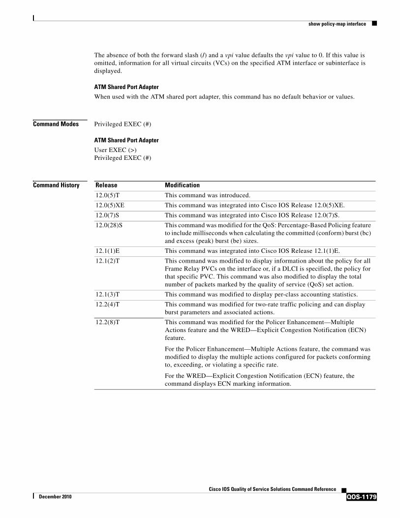
show policy-map interface
QOS-1179Cisco IOS Quality of Service Solutions Command Reference
December 2010
The absence of both the forward slash (/) and a vpi value defaults the vpi value to 0. If this value is omitted, information for all virtual circuits (VCs) on the specified ATM interface or subinterface is displayed.
ATM Shared Port Adapter
When used with the ATM shared port adapter, this command has no default behavior or values.
Command Modes Privileged EXEC (#)
ATM Shared Port Adapter
User EXEC (>)Privileged EXEC (#)
Command History Release Modification
12.0(5)T This command was introduced.
12.0(5)XE This command was integrated into Cisco IOS Release 12.0(5)XE.
12.0(7)S This command was integrated into Cisco IOS Release 12.0(7)S.
12.0(28)S This command was modified for the QoS: Percentage-Based Policing feature to include milliseconds when calculating the committed (conform) burst (bc) and excess (peak) burst (be) sizes.
12.1(1)E This command was integrated into Cisco IOS Release 12.1(1)E.
12.1(2)T This command was modified to display information about the policy for all Frame Relay PVCs on the interface or, if a DLCI is specified, the policy for that specific PVC. This command was also modified to display the total number of packets marked by the quality of service (QoS) set action.
12.1(3)T This command was modified to display per-class accounting statistics.
12.2(4)T This command was modified for two-rate traffic policing and can display burst parameters and associated actions.
12.2(8)T This command was modified for the Policer Enhancement—Multiple Actions feature and the WRED—Explicit Congestion Notification (ECN) feature.
For the Policer Enhancement—Multiple Actions feature, the command was modified to display the multiple actions configured for packets conforming to, exceeding, or violating a specific rate.
For the WRED—Explicit Congestion Notification (ECN) feature, the command displays ECN marking information.

show policy-map interface
QOS-1180Cisco IOS Quality of Service Solutions Command Reference
December 2010
12.2(13)T The following modifications were made:
• This command was modified for the Percentage-Based Policing and Shaping feature.
• This command was modified for the Class-Based RTP and TCP Header Compression feature.
• This command was modified as part of the Modular QoS CLI (MQC) Unconditional Packet Discard feature. Traffic classes in policy maps can now be configured to discard packets belonging to a specified class.
• This command was modified to display the Frame Relay DLCI number as a criterion for matching traffic inside a class map.
• This command was modified to display Layer 3 packet length as a criterion for matching traffic inside a class map.
• This command was modified for the Enhanced Packet Marking feature. A mapping table (table map) can now be used to convert and propagate packet-marking values.
12.2(14)SX This command was modified. Support for this command was introduced on Cisco 7600 series routers.
12.2(15)T This command was modified to display Frame Relay voice-adaptive traffic-shaping information.
12.2(17d)SXB This command was implemented on the Supervisor Engine 2 and integrated into Cisco IOS Release 12.2(17d)SXB.
12.3(14)T This command was modified to display bandwidth estimation parameters.
12.2(18)SXE This command was integrated into Cisco IOS Release 12.2(18)SXE. This command was modified to display aggregate WRED statistics for the ATM shared port adapter. Note that changes were made to the syntax, defaults, and command modes. These changes are labelled “ATM Shared Port Adapter.”
12.4(4)T This command was modified. The type access-control keywords were added to support flexible packet matching.
12.2(28)SB This command was integrated into Cisco IOS Release 12.2(28)SB, and the following modifications were made:
• This command was modified to display either legacy (undistributed processing) QoS or hierarchical queueing framework (HQF) parameters on Frame Relay interfaces or PVCs.
• This command was modified to display information about Layer 2 Tunnel Protocol Version 3 (L2TPv3) tunnel marking.
12.2(31)SB2 The following modifications were made:
• This command was enhanced to display statistical information for each level of priority service configured and information about bandwidth-remaining ratios, and this command was implemented on the Cisco 10000 series router for the PRE3.
• This command was modified to display statistics for matching packets on the basis of VLAN identification numbers. As of Cisco IOS Release 12.2(31)SB2, matching packets on the basis of VLAN identification numbers is supported on Cisco 10000 series routers only.
12.2(33)SRC This command was integrated into Cisco IOS Release 12.2(33)SRC.
Release Modification

show policy-map interface
QOS-1181Cisco IOS Quality of Service Solutions Command Reference
December 2010
Usage Guidelines Cisco 3660, 3845, 7200, 7400, 7500, and Cisco ASR 1000 Series Routers
The show policy-map interface command displays the packet statistics for classes on the specified interface or the specified PVC only if a service policy has been attached to the interface or the PVC.
The counters displayed after the show policy-map interface command is entered are updated only if congestion is present on the interface.
The show policy-map interface command displays policy information about Frame Relay PVCs only if Frame Relay Traffic Shaping (FRTS) is enabled on the interface.
The show policy-map interface command displays ECN marking information only if ECN is enabled on the interface.
To determine if shaping is active with HQF, check the queue depth field of the “(queue depth/total drops/no-buffer drops)” line in the show policy-map interface command output.
In HQF images for Cisco IOS Releases 12.4(20)T and later, the packets delayed and the bytes delayed counters were removed for traffic shaping classes.
Cisco 7600 Series Routers and Catalyst 6500 Series Switches
The pos, atm, and ge-wan interfaces are not supported on Cisco 7600 series routers or Catalyst 6500 series switches that are configured with a Supervisor Engine 720.
Cisco 7600 series routers and Catalyst 6500 series switches that are configured with a Supervisor Engine 2 display packet counters.
Cisco 7600 series routers and Catalyst 6500 series switches that are configured with a Supervisor Engine 720 display byte counters.
The output does not display policed-counter information; 0 is displayed in its place (for example, 0 packets, 0 bytes). To display dropped and forwarded policed-counter information, enter the show mls qos command.
12.4(15)T2 This command was modified to display information about Generic Routing Encapsulation (GRE) tunnel marking.
Note As of this release, GRE-tunnel marking is supported on the Cisco MGX Route Processor Module (RPM-XF) platform only.
12.2(33)SB This command was modified to display information about GRE-tunnel marking, and support for the Cisco 7300 series router was added.
Cisco IOS XE 2.1 This command was integrated into Cisco IOS XE Release 2.1 and was implemented on the Cisco ASR 1000 series router.
12.4(20)T This command was modified. Support was added for hierarchical queueing framework (HQF) using the Modular Quality of Service (QoS) Command-Line Interface (CLI) (MQC).
12.2(33)SXI This command was implemented on the Catalyst 6500 series switch and modified to display the strict level in the priority feature and the counts per level.
12.2SR This command was modified to automatically round off the bc and be values, in the MQC police policy map, to the interface’s MTU size.
Cisco IOS XE Release 2.6
The command output was modified to display information about subscriber QoS statistics.
Release Modification

show policy-map interface
QOS-1182Cisco IOS Quality of Service Solutions Command Reference
December 2010
On the Cisco 7600 series router, for OSM WAN interfaces only, if you configure policing within a policy map, the hardware counters are displayed and the class-default counters are not displayed. If you do not configure policing within a policy map, the class-default counters are displayed.
On the Catalyst 6500 series switch, the show policy-map interface command displays the strict level in the priority feature and the counts per level.
The interface-number argument designates the module and port number. Valid values for interface-number depend on the specified interface type and the chassis and module that are used. For example, if you specify a Gigabit Ethernet interface and have a 48-port 10/100BASE-T Ethernet module that is installed in a 13-slot chassis, valid values for the module number are from 1 to 13 and valid values for the port number are from 1 to 48.
HQF
When you configure HQF, the show policy-map interface command displays additional fields that include the differentiated services code point (DSCP) value, WRED statistics in bytes, transmitted packets by WRED, and a counter that displays packets output/bytes output in each class.
Examples This section provides sample output from typical show policy-map interface commands. Depending upon the interface or platform in use and the options enabled, the output you see may vary slightly from the ones shown below.
• Weighted Fair Queueing (WFQ) on Serial Interface: Example, page 1183
• Traffic Shaping on Serial Interface: Example, page 1184
• Precedence-Based Aggregate WRED on ATM Shared Port Adapter: Example, page 1187
• DSCP-Based Aggregate WRED on ATM Shared Port Adapter: Example, page 1188
• Frame Relay Voice-Adaptive Traffic-Shaping: Example, page 1190
• Two-Rate Traffic Policing: Example, page 1190
• Multiple Traffic Policing Actions: Example, page 1191
• Explicit Congestion Notification: Example, page 1192
• Class-Based RTP and TCP Header Compression: Example, page 1194
• Modular QoS CLI (MQC) Unconditional Packet Discard: Example, page 1196
• Percentage-Based Policing and Shaping: Example, page 1197
• Traffic Shaping: Example, page 1198
• Packet Classification Based on Layer 3 Packet Length: Example, page 1200
• Enhanced Packet Marking: Example, page 1201
• Traffic Policing: Example, page 1202
• Formula for Calculating the CIR: Example, page 1203
• Formula for Calculating the PIR: Example, page 1203
• Formula for Calculating the Committed Burst (bc): Example, page 1204
• Formula for Calculating the Excess Burst (be): Example, page 1204
• Bandwidth Estimation: Example, page 1205
• Shaping with HQF Enabled: Example, page 1205
• Packets Matched on the Basis of VLAN ID Number: Example, page 1206

show policy-map interface
QOS-1183Cisco IOS Quality of Service Solutions Command Reference
December 2010
• Cisco 7600 Series Routers: Example, page 1207
• Multiple Priority Queues on Serial Interface: Example, page 1209
• Bandwidth-Remaining Ratios: Example, page 1209
• Tunnel Marking: Example, page 1211
• Traffic Shaping Overhead Accounting for ATM: Example, page 1212
• HQF: Example, page 1213
• Account QoS Statistics for the Cisco ASR 1000 Series Aggregation Services Routers: Example, page 1215
Weighted Fair Queueing (WFQ) on Serial Interface: Example
The following sample output of the show policy-map interface command displays the statistics for the serial 3/1 interface, to which a service policy called mypolicy (configured as shown below) is attached. Weighted fair queueing (WFQ) has been enabled on this interface. See Table 193 for an explanation of the significant fields that commonly appear in the command output.
policy-map mypolicyclass voicepriority 128
class goldbandwidth 100
class silverbandwidth 80random-detect
Router# show policy-map interface serial3/1 output
Serial3/1
Service-policy output: mypolicy
Class-map: voice (match-all) 0 packets, 0 bytes 5 minute offered rate 0 bps, drop rate 0 bps Match: ip precedence 5 Weighted Fair Queueing Strict Priority Output Queue: Conversation 264 Bandwidth 128 (kbps) Burst 3200 (Bytes) (pkts matched/bytes matched) 0/0 (total drops/bytes drops) 0/0
Class-map: gold (match-all) 0 packets, 0 bytes 5 minute offered rate 0 bps, drop rate 0 bps Match: ip precedence 2 Weighted Fair Queueing Output Queue: Conversation 265 Bandwidth 100 (kbps) Max Threshold 64 (packets) (pkts matched/bytes matched) 0/0 (depth/total drops/no-buffer drops) 0/0/0
Class-map: silver (match-all) 0 packets, 0 bytes 5 minute offered rate 0 bps, drop rate 0 bps Match: ip precedence 1 Weighted Fair Queueing Output Queue: Conversation 266 Bandwidth 80 (kbps)
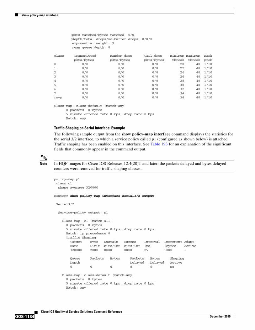
show policy-map interface
QOS-1184Cisco IOS Quality of Service Solutions Command Reference
December 2010
(pkts matched/bytes matched) 0/0 (depth/total drops/no-buffer drops) 0/0/0 exponential weight: 9 mean queue depth: 0
class Transmitted Random drop Tail drop Minimum Maximum Mark pkts/bytes pkts/bytes pkts/bytes thresh thresh prob0 0/0 0/0 0/0 20 40 1/101 0/0 0/0 0/0 22 40 1/102 0/0 0/0 0/0 24 40 1/103 0/0 0/0 0/0 26 40 1/104 0/0 0/0 0/0 28 40 1/105 0/0 0/0 0/0 30 40 1/106 0/0 0/0 0/0 32 40 1/107 0/0 0/0 0/0 34 40 1/10rsvp 0/0 0/0 0/0 36 40 1/10
Class-map: class-default (match-any) 0 packets, 0 bytes 5 minute offered rate 0 bps, drop rate 0 bps Match: any
Traffic Shaping on Serial Interface: Example
The following sample output from the show policy-map interface command displays the statistics for the serial 3/2 interface, to which a service policy called p1 (configured as shown below) is attached. Traffic shaping has been enabled on this interface. See Table 193 for an explanation of the significant fields that commonly appear in the command output.
Note In HQF images for Cisco IOS Releases 12.4(20)T and later, the packets delayed and bytes delayed counters were removed for traffic shaping classes.
policy-map p1class c1shape average 320000
Router# show policy-map interface serial3/2 output
Serial3/2
Service-policy output: p1
Class-map: c1 (match-all) 0 packets, 0 bytes 5 minute offered rate 0 bps, drop rate 0 bps Match: ip precedence 0 Traffic Shaping Target Byte Sustain Excess Interval Increment Adapt Rate Limit bits/int bits/int (ms) (bytes) Active 320000 2000 8000 8000 25 1000 -
Queue Packets Bytes Packets Bytes Shaping Depth Delayed Delayed Active 0 0 0 0 0 no
Class-map: class-default (match-any) 0 packets, 0 bytes 5 minute offered rate 0 bps, drop rate 0 bps Match: any

show policy-map interface
QOS-1185Cisco IOS Quality of Service Solutions Command Reference
December 2010
Table 193 describes significant fields commonly shown in the displays. The fields in the table are grouped according to the relevant QoS feature.
Table 193 show policy-map interface Field Descriptions1
Field Description
Fields Associated with Classes or Service Policies
Service-policy output Name of the output service policy applied to the specified interface or VC.
Class-map Class of traffic being displayed. Output is displayed for each configured class in the policy. The choice for implementing class matches (for example, match-all or match-any) can also appear next to the traffic class.
packets and bytes Number of packets (also shown in bytes) identified as belonging to the class of traffic being displayed.
offered rate Rate, in kbps, of packets coming in to the class.
Note If the packets are compressed over an outgoing interface, the improved packet rate achieved by packet compression is not reflected in the offered rate. Also, if the packets are classified before they enter a combination of tunnels (for example, a generic routing encapsulation (GRE) tunnel and an IP Security (IPSec) tunnel), the offered rate does not include all the extra overhead associated with tunnel encapsulation in general. Depending on the configuration, the offered rate may include no overhead, may include the overhead for only one tunnel encapsulation, or may include the overhead for all tunnel encapsulations. In most of the GRE and IPSec tunnel configurations, the offered rate includes the overhead for GRE tunnel encapsulation only.
drop rate Rate, in kbps, at which packets are dropped from the class. The drop rate is calculated by subtracting the number of successfully transmitted packets from the offered rate.
Note In distributed architecture platforms (such as the Cisco 7500 series platform), the value of the transfer rate, calculated as the difference between the offered rate and the drop rate counters, can sporadically deviate from the average by up to 20 percent or more. This can occur while no corresponding burst is registered by independent traffic analyser equipment.
Match Match criteria specified for the class of traffic. Choices include criteria such as IP precedence, IP differentiated services code point (DSCP) value, Multiprotocol Label Switching (MPLS) experimental (EXP) value, access groups, and QoS groups. For more information about the variety of match criteria that are available, see the “Classifying Network Traffic” module in the Cisco IOS Quality of Service Solutions Configuration Guide.

show policy-map interface
QOS-1186Cisco IOS Quality of Service Solutions Command Reference
December 2010
Fields Associated with Queueing (if Enabled)
Output Queue The weighted fair queueing (WFQ) conversation to which this class of traffic is allocated.
Bandwidth Bandwidth, in either kbps or percentage, configured for this class and the burst size.
pkts matched/bytes matched
Number of packets (also shown in bytes) matching this class that were placed in the queue. This number reflects the total number of matching packets queued at any time. Packets matching this class are queued only when congestion exists. If packets match the class but are never queued because the network was not congested, those packets are not included in this total. However, if process switching is in use, the number of packets is always incremented even if the network is not congested.
depth/total drops/no-buffer drops
Number of packets discarded for this class. No-buffer indicates that no memory buffer exists to service the packet.
Fields Associated with Weighted Random Early Detection (WRED) (if Enabled)
exponential weight Exponent used in the average queue size calculation for a WRED parameter group.
mean queue depth Average queue depth based on the actual queue depth on the interface and the exponential weighting constant. It is a fluctuating average. The minimum and maximum thresholds are compared against this value to determine drop decisions.
class IP precedence level.
Transmitted pkts/bytes Number of packets (also shown in bytes) passed through WRED and not dropped by WRED.
Note If there is insufficient memory in the buffer to accommodate the packet, the packet can be dropped after the packet passes through WRED. Packets dropped because of insufficient memory in the buffer (sometimes referred to as “no-buffer drops”) are not taken into account by the WRED packet counter.
Random drop pkts/bytes Number of packets (also shown in bytes) randomly dropped when the mean queue depth is between the minimum threshold value and the maximum threshold value for the specified IP precedence level.
Tail drop pkts/bytes Number of packets dropped when the mean queue depth is greater than the maximum threshold value for the specified IP precedence level.
Minimum thresh Minimum threshold. Minimum WRED threshold in number of packets.
Maximum thresh Maximum threshold. Maximum WRED threshold in number of packets.
Mark prob Mark probability. Fraction of packets dropped when the average queue depth is at the maximum threshold.
Table 193 show policy-map interface Field Descriptions1 (continued)
Field Description

show policy-map interface
QOS-1187Cisco IOS Quality of Service Solutions Command Reference
December 2010
Precedence-Based Aggregate WRED on ATM Shared Port Adapter: Example
The following sample output of the show policy-map interface command displays the statistics for the ATM shared port adapter interface 4/1/0.10, to which a service policy called prec-aggr-wred (configured as shown below) is attached. Because aggregate WRED has been enabled on this interface, the class through Mark Prob statistics are aggregated by subclasses. See Table 194 for an explanation of the significant fields that commonly appear in the command output.
Router(config)# policy-map prec-aggr-wredRouter(config-pmap)# class class-defaultRouter(config-pmap-c)# random-detect aggregateRouter(config-pmap-c)# random-detect precedence values 0 1 2 3 minimum thresh 10 maximum-thresh 100 mark-prob 10Router(config-pmap-c)# random-detect precedence values 4 5 minimum-thresh 40 maximum-thresh 400 mark-prob 10Router(config-pmap-c)# random-detect precedence values 6 minimum-thresh 60 maximum-thresh 600 mark-prob 10Router(config-pmap-c)# random-detect precedence values 7 minimum-thresh 70 maximum-thresh 700 mark-prob 10Router(config-pmap-c)# exitRouter(config-pmap)# exitRouter(config)# interface ATM4/1/0.10 point-to-point
Fields Associated with Traffic Shaping (if Enabled)
Target Rate Rate used for shaping traffic.
Byte Limit Maximum number of bytes that can be transmitted per interval. Calculated as follows:
((Bc+Be) /8) x 1
Sustain bits/int Committed burst (Bc) rate.
Excess bits/int Excess burst (Be) rate.
Interval (ms) Time interval value in milliseconds (ms).
Increment (bytes) Number of credits (in bytes) received in the token bucket of the traffic shaper during each time interval.
Queue Depth Current queue depth of the traffic shaper.
Packets Total number of packets that have entered the traffic shaper system.
Bytes Total number of bytes that have entered the traffic shaper system.
Packets Delayed Total number of packets delayed in the queue of the traffic shaper before being transmitted.
Bytes Delayed Total number of bytes delayed in the queue of the traffic shaper before being transmitted.
Shaping Active Indicates whether the traffic shaper is active. For example, if a traffic shaper is active, and the traffic being sent exceeds the traffic shaping rate, a “yes” appears in this field.
1. A number in parentheses may appear next to the service-policy output name, class-map name, and match criteria information. The number is for Cisco internal use only and can be disregarded.
Table 193 show policy-map interface Field Descriptions1 (continued)
Field Description

show policy-map interface
QOS-1188Cisco IOS Quality of Service Solutions Command Reference
December 2010
Router(config-if)# ip address 10.0.0.2 255.255.255.0Router(config-if)# pvc 10/110Router(config-if)# service-policy output prec-aggr-wred
Router# show policy-map interface atm4/1/0.10
ATM4/1/0.10: VC 10/110 -
Service-policy output: prec-aggr-wred
Class-map: class-default (match-any) 0 packets, 0 bytes 5 minute offered rate 0 bps, drop rate 0 bps Match: any Exp-weight-constant: 9 (1/512) Mean queue depth: 0 class Transmitted Random drop Tail drop Minimum Maximum Mark
pkts/bytespkts/bytespkts/bytesthreshthreshprob 0 1 2 3 0/0 0/0 0/0 10 100 1/10 4 5 0/0 0/0 0/0 40 400 1/10 6 0/0 0/0 0/0 60 600 1/10 7 0/0 0/0 0/0 70 700 1/10
DSCP-Based Aggregate WRED on ATM Shared Port Adapter: Example
The following sample output of the show policy-map interface command displays the statistics for the ATM shared port adapter interface 4/1/0.11, to which a service policy called dscp-aggr-wred (configured as shown below) is attached. Because aggregate WRED has been enabled on this interface, the class through Mark Prob statistics are aggregated by subclasses. See Table 194 for an explanation of the significant fields that commonly appear in the command output.
Router(config)# policy-map dscp-aggr-wredRouter(config-pmap)# class class-defaultRouter(config-pmap-c)# random-detect dscp-based aggregate minimum-thresh 1 maximum-thresh 10 mark-prob 10Router(config-pmap-c)# random-detect dscp values 0 1 2 3 4 5 6 7 minimum-thresh 10 maximum-thresh 20 mark-prob 10Router(config-pmap-c)# random-detect dscp values 8 9 10 11 minimum-thresh 10 maximum-thresh 40 mark-prob 10Router(config-pmap-c)# exitRouter(config-pmap)# exitRouter(config)# interface ATM4/1/0.11 point-to-pointRouter(config-subif)# ip address 10.0.0.2 255.255.255.0Router(config-subif)# pvc 11/101Router(config-subif)# service-policy output dscp-aggr-wred
Router# show policy-map interface atm4/1/0.11
ATM4/1/0.11: VC 11/101 -
Service-policy output: dscp-aggr-wred
Class-map: class-default (match-any) 0 packets, 0 bytes 5 minute offered rate 0 bps, drop rate 0 bps
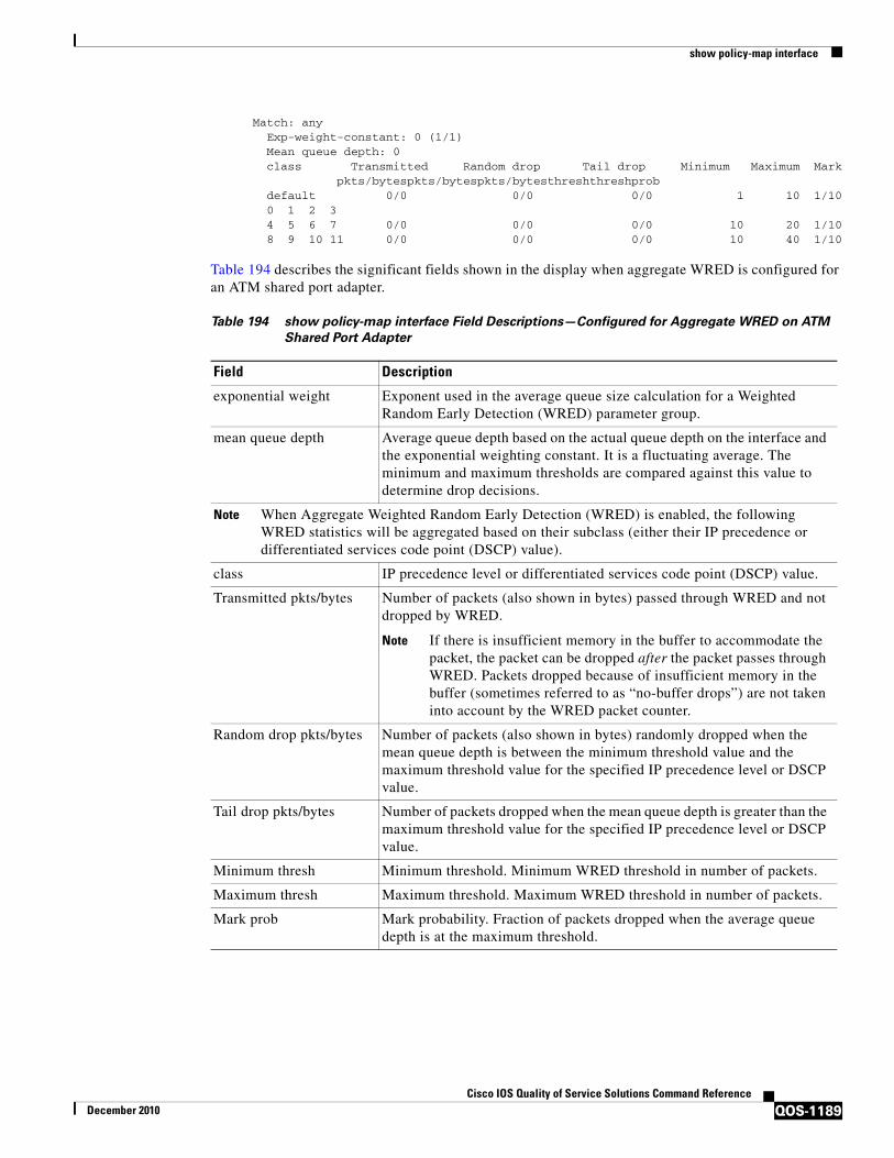
show policy-map interface
QOS-1189Cisco IOS Quality of Service Solutions Command Reference
December 2010
Match: any Exp-weight-constant: 0 (1/1) Mean queue depth: 0 class Transmitted Random drop Tail drop Minimum Maximum Mark pkts/bytespkts/bytespkts/bytesthreshthreshprob default 0/0 0/0 0/0 1 10 1/10 0 1 2 3 4 5 6 7 0/0 0/0 0/0 10 20 1/10 8 9 10 11 0/0 0/0 0/0 10 40 1/10
Table 194 describes the significant fields shown in the display when aggregate WRED is configured for an ATM shared port adapter.
Table 194 show policy-map interface Field Descriptions—Configured for Aggregate WRED on ATM
Shared Port Adapter
Field Description
exponential weight Exponent used in the average queue size calculation for a Weighted Random Early Detection (WRED) parameter group.
mean queue depth Average queue depth based on the actual queue depth on the interface and the exponential weighting constant. It is a fluctuating average. The minimum and maximum thresholds are compared against this value to determine drop decisions.
Note When Aggregate Weighted Random Early Detection (WRED) is enabled, the following WRED statistics will be aggregated based on their subclass (either their IP precedence or differentiated services code point (DSCP) value).
class IP precedence level or differentiated services code point (DSCP) value.
Transmitted pkts/bytes Number of packets (also shown in bytes) passed through WRED and not dropped by WRED.
Note If there is insufficient memory in the buffer to accommodate the packet, the packet can be dropped after the packet passes through WRED. Packets dropped because of insufficient memory in the buffer (sometimes referred to as “no-buffer drops”) are not taken into account by the WRED packet counter.
Random drop pkts/bytes Number of packets (also shown in bytes) randomly dropped when the mean queue depth is between the minimum threshold value and the maximum threshold value for the specified IP precedence level or DSCP value.
Tail drop pkts/bytes Number of packets dropped when the mean queue depth is greater than the maximum threshold value for the specified IP precedence level or DSCP value.
Minimum thresh Minimum threshold. Minimum WRED threshold in number of packets.
Maximum thresh Maximum threshold. Maximum WRED threshold in number of packets.
Mark prob Mark probability. Fraction of packets dropped when the average queue depth is at the maximum threshold.
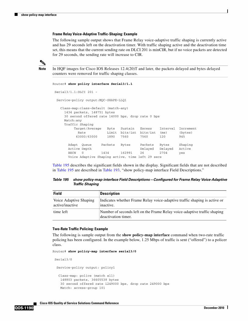
show policy-map interface
QOS-1190Cisco IOS Quality of Service Solutions Command Reference
December 2010
Frame Relay Voice-Adaptive Traffic-Shaping: Example
The following sample output shows that Frame Relay voice-adaptive traffic shaping is currently active and has 29 seconds left on the deactivation timer. With traffic shaping active and the deactivation time set, this means that the current sending rate on DLCI 201 is minCIR, but if no voice packets are detected for 29 seconds, the sending rate will increase to CIR.
Note In HQF images for Cisco IOS Releases 12.4(20)T and later, the packets delayed and bytes delayed counters were removed for traffic shaping classes.
Router# show policy interface Serial3/1.1
Serial3/1.1:DLCI 201 -
Service-policy output:MQC-SHAPE-LLQ1 Class-map:class-default (match-any) 1434 packets, 148751 bytes 30 second offered rate 14000 bps, drop rate 0 bps Match:any Traffic Shaping Target/Average Byte Sustain Excess Interval Increment Rate Limit bits/int bits/int (ms) (bytes) 63000/63000 1890 7560 7560 120 945 Adapt Queue Packets Bytes Packets Bytes Shaping Active Depth Delayed Delayed Active BECN 0 1434 162991 26 2704 yes Voice Adaptive Shaping active, time left 29 secs
Table 195 describes the significant fields shown in the display. Significant fields that are not described in Table 195 are described in Table 193, “show policy-map interface Field Descriptions.”
Two-Rate Traffic Policing: Example
The following is sample output from the show policy-map interface command when two-rate traffic policing has been configured. In the example below, 1.25 Mbps of traffic is sent (“offered”) to a policer class.
Router# show policy-map interface serial3/0
Serial3/0
Service-policy output: policy1
Class-map: police (match all)148803 packets, 36605538 bytes30 second offered rate 1249000 bps, drop rate 249000 bpsMatch: access-group 101
Table 195 show policy-map interface Field Descriptions—Configured for Frame Relay Voice-Adaptive
Traffic Shaping
Field Description
Voice Adaptive Shaping active/inactive
Indicates whether Frame Relay voice-adaptive traffic shaping is active or inactive.
time left Number of seconds left on the Frame Relay voice-adaptive traffic shaping deactivation timer.

show policy-map interface
QOS-1191Cisco IOS Quality of Service Solutions Command Reference
December 2010
police:cir 500000 bps, conform-burst 10000, pir 1000000, peak-burst 100000conformed 59538 packets, 14646348 bytes; action: transmitexceeded 59538 packets, 14646348 bytes; action: set-prec-transmit 2violated 29731 packets, 7313826 bytes; action: dropconformed 499000 bps, exceed 500000 bps violate 249000 bps
Class-map: class-default (match-any)19 packets, 1990 bytes30 seconds offered rate 0 bps, drop rate 0 bpsMatch: any
The two-rate traffic policer marks 500 kbps of traffic as conforming, 500 kbps of traffic as exceeding, and 250 kbps of traffic as violating the specified rate. Packets marked as conforming will be sent as is, and packets marked as exceeding will be marked with IP Precedence 2 and then sent. Packets marked as violating the specified rate are dropped.
Table 196 describes the significant fields shown in the display.
Multiple Traffic Policing Actions: Example
The following is sample output from the show policy-map command when the Policer Enhancement—Multiple Actions feature has been configured. The sample output from the show policy-map interface command displays the statistics for the serial 3/2 interface, to which a service policy called “police” (configured as shown below) is attached.
policy-map policeclass class-defaultpolice cir 1000000 pir 2000000conform-action transmit exceed-action set-prec-transmit 4exceed-action set-frde-transmit violate-action set-prec-transmit 2violate-action set-frde-transmit
Router# show policy-map interface serial3/2
Serial3/2: DLCI 100 -
Service-policy output: police
Class-map: class-default (match-any) 172984 packets, 42553700 bytes 5 minute offered rate 960000 bps, drop rate 277000 bps Match: any police:
Table 196 show policy-map interface Field Descriptions—Configured for Two-Rate Traffic Policing
Field Description
police Indicates that the police command has been configured to enable traffic policing. Also, displays the specified CIR, conform burst size, peak information rate (PIR), and peak burst size used for marking packets.
conformed Displays the action to be taken on packets conforming to a specified rate. Displays the number of packets and bytes on which the action was taken.
exceeded Displays the action to be taken on packets exceeding a specified rate. Displays the number of packets and bytes on which the action was taken.
violated Displays the action to be taken on packets violating a specified rate. Displays the number of packets and bytes on which the action was taken.

show policy-map interface
QOS-1192Cisco IOS Quality of Service Solutions Command Reference
December 2010
cir 1000000 bps, bc 31250 bytes, pir 2000000 bps, be 31250 bytes conformed 59679 packets, 14680670 bytes; actions: transmit exceeded 59549 packets, 14649054 bytes; actions: set-prec-transmit 4 set-frde-transmit violated 53758 packets, 13224468 bytes; actions:
set-prec-transmit 2 set-frde-transmit conformed 340000 bps, exceed 341000 bps, violate 314000 bps
The sample output from show policy-map interface command shows the following:
• 59679 packets were marked as conforming packets (that is, packets conforming to the CIR) and were transmitted unaltered.
• 59549 packets were marked as exceeding packets (that is, packets exceeding the CIR but not exceeding the PIR). Therefore, the IP Precedence value of these packets was changed to an IP Precedence level of 4, the discard eligibility (DE) bit was set to 1, and the packets were transmitted with these changes.
• 53758 packets were marked as violating packets (that is, exceeding the PIR). Therefore, the IP Precedence value of these packets was changed to an IP Precedence level of 2, the DE bit was set to 1, and the packets were transmitted with these changes.
Note Actions are specified by using the action argument of the police command. For more information about the available actions, see the police command reference page.
Table 197 describes the significant fields shown in the display.
Explicit Congestion Notification: Example
The following is sample output from the show policy-map interface command when the WRED — Explicit Congestion Notification (ECN) feature has been configured. The words “explicit congestion notification” included in the output indicate that ECN has been enabled.
Table 197 show policy-map interface Field Descriptions—Configured for Multiple Traffic Policing
Actions
Field Description
police Indicates that the police command has been configured to enable traffic policing. Also, displays the specified CIR, conform burst size (BC), PIR, and peak burst size (BE) used for marking packets.
conformed, packets, bytes, actions
Displays the number of packets (also shown in bytes) marked as conforming to a specified rate and the actions taken on the packet. If there are multiple actions, each action is listed separately.
exceeded, packets, bytes, actions
Displays the number of packets (also shown in bytes) marked as exceeding a specified rate and the actions taken on the packet. If there are multiple actions, each action is listed separately.
violated, packets, bytes, actions
Displays the number of packets (also shown in bytes) marked as violating a specified rate and the actions taken on the packet. If there are multiple actions, each action is listed separately.

show policy-map interface
QOS-1193Cisco IOS Quality of Service Solutions Command Reference
December 2010
Router# show policy-map interface Serial4/1
Serial4/1
Service-policy output:policy_ecn Class-map:prec1 (match-all) 1000 packets, 125000 bytes 30 second offered rate 14000 bps, drop rate 5000 bps Match:ip precedence 1 Weighted Fair Queueing Output Queue:Conversation 42 Bandwidth 20 (%) Bandwidth 100 (kbps) (pkts matched/bytes matched) 989/123625 (depth/total drops/no-buffer drops) 0/455/0 exponential weight:9 explicit congestion notification mean queue depth:0
class Transmitted Random drop Tail drop Minimum Maximum Markpkts/bytes pkts/bytes pkts/bytes threshold threshold probability
0 0/0 0/0 0/0 20 40 1/10 1 545/68125 0/0 0/0 22 40 1/10 2 0/0 0/0 0/0 24 40 1/10 3 0/0 0/0 0/0 26 40 1/10 4 0/0 0/0 0/0 28 40 1/10 5 0/0 0/0 0/0 30 40 1/10 6 0/0 0/0 0/0 32 40 1/10 7 0/0 0/0 0/0 34 40 1/10 rsvp 0/0 0/0 0/0 36 40 1/10
class ECN Mark pkts/bytes
0 0/01 43/53752 0/03 0/04 0/05 0/06 0/07 0/0
rsvp 0/0
Table 198 describes the significant fields shown in the display.
Table 198 show policy-map interface Field Descriptions—Configured for ECN
Field Description
explicit congestion notification
Indication that Explicit Congestion Notification is enabled.
mean queue depth Average queue depth based on the actual queue depth on the interface and the exponential weighting constant. It is a moving average. The minimum and maximum thresholds are compared against this value to determine drop decisions.
class IP precedence value.

show policy-map interface
QOS-1194Cisco IOS Quality of Service Solutions Command Reference
December 2010
Class-Based RTP and TCP Header Compression: Example
The following sample output from the show policy-map interface command shows the RTP header compression has been configured for a class called “prec2” in the policy map called “p1”.
The show policy-map interface command output displays the type of header compression configured (RTP), the interface to which the policy map called “p1” is attached (Serial 4/1), the total number of packets, the number of packets compressed, the number of packets saved, the number of packets sent, and the rate at which the packets were compressed (in bits per second (bps)).
In this example, User Datagram Protocol (UDP)/RTP header compressions have been configured, and the compression statistics are included at the end of the display.
Router# show policy-map interface Serial4/1
Serial4/1
Service-policy output:p1
Class-map:class-default (match-any) 1005 packets, 64320 bytes 30 second offered rate 16000 bps, drop rate 0 bps Match:anycompress: header ip rtp UDP/RTP Compression: Sent:1000 total, 999 compressed, 41957 bytes saved, 17983 bytes sent 3.33 efficiency improvement factor 99% hit ratio, five minute miss rate 0 misses/sec, 0 max
rate 5000 bps
Transmitted pkts/bytes Number of packets (also shown in bytes) passed through WRED and not dropped by WRED.
Note If there is insufficient memory in the buffer to accommodate the packet, the packet can be dropped after the packet passes through WRED. Packets dropped because of insufficient memory in the buffer (sometimes referred to as “no-buffer drops”) are not taken into account by the WRED packet counter.
Random drop pkts/bytes Number of packets (also shown in bytes) randomly dropped when the mean queue depth is between the minimum threshold value and the maximum threshold value for the specified IP precedence value.
Tail drop pkts/bytes Number of packets dropped when the mean queue depth is greater than the maximum threshold value for the specified IP precedence value.
Minimum threshold Minimum WRED threshold in number of packets.
Maximum threshold Maximum WRED threshold in number of packets.
Mark probability Fraction of packets dropped when the average queue depth is at the maximum threshold.
ECN Mark pkts/bytes Number of packets (also shown in bytes) marked by ECN.
Table 198 show policy-map interface Field Descriptions—Configured for ECN (continued)
Field Description

show policy-map interface
QOS-1195Cisco IOS Quality of Service Solutions Command Reference
December 2010
Table 199 describes the significant fields shown in the display.
Table 199 show policy-map interface Field Descriptions—Configured for Class-Based RTP and TCP
Header Compression1
1. A number in parentheses may appear next to the service-policy output name and the class-map name. The number is for Cisco internal use only and can be disregarded.
Field Description
Service-policy output Name of the output service policy applied to the specified interface or VC.
Class-map Class of traffic being displayed. Output is displayed for each configured class in the policy. The choice for implementing class matches (for example, match-all or match-any) can also appear next to the traffic class.
packets, bytes Number of packets (also shown in bytes) identified as belonging to the class of traffic being displayed.
offered rate Rate, in kbps, of packets coming in to the class.
Note If the packets are compressed over an outgoing interface, the improved packet rate achieved by packet compression is not reflected in the offered rate. Also, if the packets are classified before they enter a combination of tunnels (for example, a generic routing encapsulation (GRE) tunnel and an IP Security (IPSec) tunnel), the offered rate does not include all the extra overhead associated with tunnel encapsulation in general. Depending on the configuration, the offered rate may include no overhead, may include the overhead for only one tunnel encapsulation, or may include the overhead for all tunnel encapsulations. In most of the GRE and IPSec tunnel configurations, the offered rate includes the overhead for GRE tunnel encapsulation only.
UDP/RTP Compression Indicates that RTP header compression has been configured for the class.
Sent total Count of every packet sent, both compressed packets and full-header packets.
Sent compressed Count of number of compressed packets sent.
bytes saved Total number of bytes saved (that is, bytes not needing to be sent).
bytes sent Total number of bytes sent for both compressed and full-header packets.
efficiency improvement factor
The percentage of increased bandwidth efficiency as a result of header compression. For example, with RTP streams, the efficiency improvement factor can be as much as 2.9 (or 290 percent).
hit ratio Used mainly for troubleshooting purposes, this is the percentage of packets found in the context database. In most instances, this percentage should be high.
five minute miss rate The number of new traffic flows found in the last five minutes.
misses/secmax
The average number of new traffic flows found per second, and the highest rate of new traffic flows to date.
rate The actual traffic rate (in bits per second) after the packets are compressed.

show policy-map interface
QOS-1196Cisco IOS Quality of Service Solutions Command Reference
December 2010
Modular QoS CLI (MQC) Unconditional Packet Discard: Example
The following sample output from the show policy-map interface command displays the statistics for the Serial2/0 interface, to which a policy map called “policy1” is attached. The discarding action has been specified for all the packets belonging to a class called “c1.” In this example, 32000 bps of traffic is sent (“offered”) to the class and all of them are dropped. Therefore, the drop rate shows 32000 bps.
Router# show policy-map interface Serial2/0
Serial2/0
Service-policy output: policy1
Class-map: c1 (match-all)10184 packets, 1056436 bytes
5 minute offered rate 32000 bps, drop rate 32000 bps Match: ip precedence 0
drop
Table 200 describes the significant fields shown in the display.
Table 200 show policy-map interface Field Descriptions—Configured for MQC Unconditional Packet
Discard1
Field Description
Service-policy output Name of the output service policy applied to the specified interface or VC.
Class-map Class of traffic being displayed. Output is displayed for each configured class in the policy. The choice for implementing class matches (for example, match-all or match-any) can also appear next to the traffic class.
packets, bytes Number of packets (also shown in bytes) identified as belonging to the class of traffic being displayed.
offered rate Rate, in kbps, of packets coming in to the class.
Note If the packets are compressed over an outgoing interface, the improved packet rate achieved by packet compression is not reflected in the offered rate. Also, if the packets are classified before they enter a combination of tunnels (for example, a generic routing encapsulation (GRE) tunnel and an IP Security (IPSec) tunnel), the offered rate does not include all the extra overhead associated with tunnel encapsulation in general. Depending on the configuration, the offered rate may include no overhead, may include the overhead for only one tunnel encapsulation, or may include the overhead for all tunnel encapsulations. In most of the GRE and IPSec tunnel configurations, the offered rate includes the overhead for GRE tunnel encapsulation only.
drop rate Rate, in kbps, at which packets are dropped from the class. The drop rate is calculated by subtracting the number of successfully transmitted packets from the offered rate.
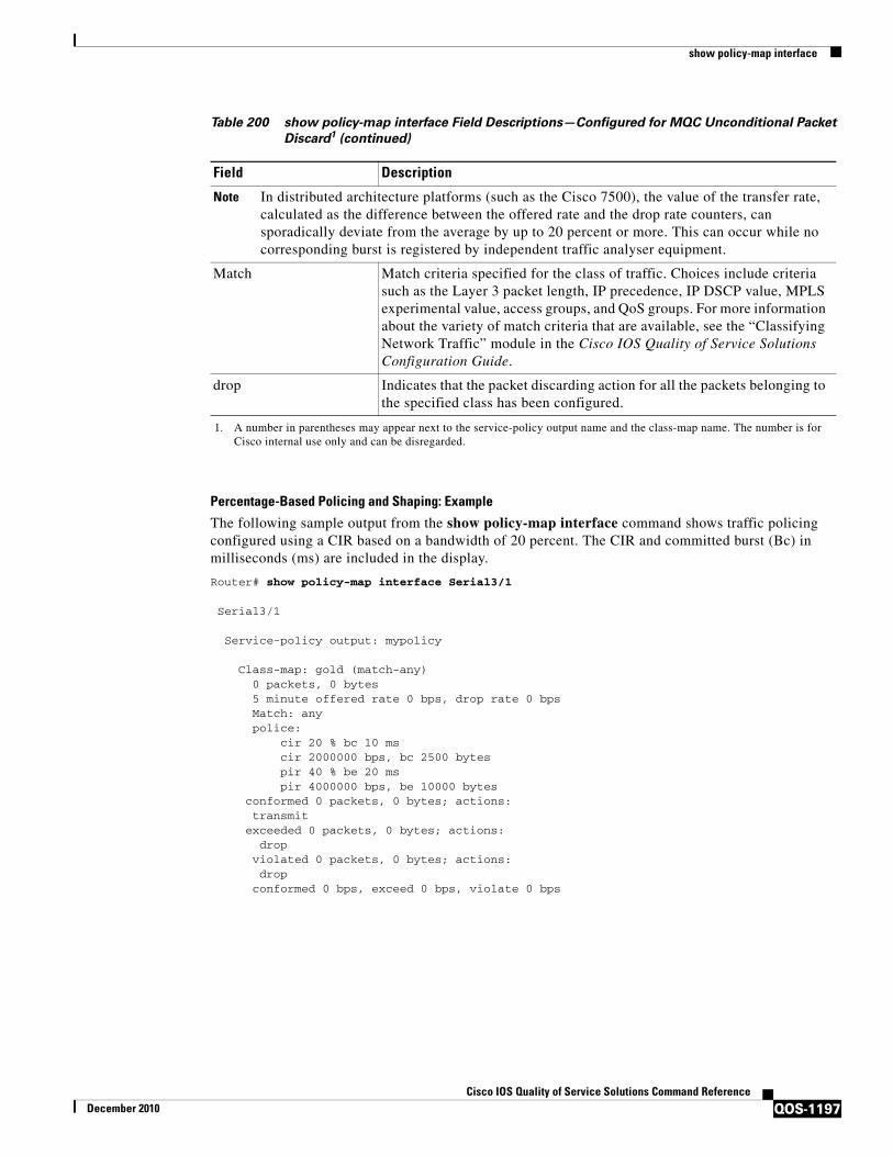
show policy-map interface
QOS-1197Cisco IOS Quality of Service Solutions Command Reference
December 2010
Percentage-Based Policing and Shaping: Example
The following sample output from the show policy-map interface command shows traffic policing configured using a CIR based on a bandwidth of 20 percent. The CIR and committed burst (Bc) in milliseconds (ms) are included in the display.
Router# show policy-map interface Serial3/1
Serial3/1
Service-policy output: mypolicy
Class-map: gold (match-any) 0 packets, 0 bytes 5 minute offered rate 0 bps, drop rate 0 bps Match: any police: cir 20 % bc 10 ms cir 2000000 bps, bc 2500 bytes pir 40 % be 20 ms pir 4000000 bps, be 10000 bytes
conformed 0 packets, 0 bytes; actions:transmit
exceeded 0 packets, 0 bytes; actions:drop
violated 0 packets, 0 bytes; actions:drop
conformed 0 bps, exceed 0 bps, violate 0 bps
Note In distributed architecture platforms (such as the Cisco 7500), the value of the transfer rate, calculated as the difference between the offered rate and the drop rate counters, can sporadically deviate from the average by up to 20 percent or more. This can occur while no corresponding burst is registered by independent traffic analyser equipment.
Match Match criteria specified for the class of traffic. Choices include criteria such as the Layer 3 packet length, IP precedence, IP DSCP value, MPLS experimental value, access groups, and QoS groups. For more information about the variety of match criteria that are available, see the “Classifying Network Traffic” module in the Cisco IOS Quality of Service Solutions Configuration Guide.
drop Indicates that the packet discarding action for all the packets belonging to the specified class has been configured.
1. A number in parentheses may appear next to the service-policy output name and the class-map name. The number is for Cisco internal use only and can be disregarded.
Table 200 show policy-map interface Field Descriptions—Configured for MQC Unconditional Packet
Discard1 (continued)
Field Description
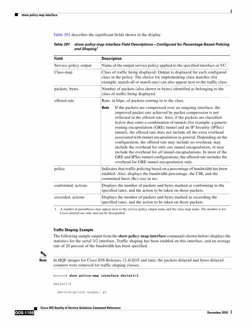
show policy-map interface
QOS-1198Cisco IOS Quality of Service Solutions Command Reference
December 2010
Table 201 describes the significant fields shown in the display.
Traffic Shaping: Example
The following sample output from the show policy-map interface command (shown below) displays the statistics for the serial 3/2 interface. Traffic shaping has been enabled on this interface, and an average rate of 20 percent of the bandwidth has been specified.
Note In HQF images for Cisco IOS Releases 12.4(20)T and later, the packets delayed and bytes delayed counters were removed for traffic shaping classes.
Router# show policy-map interface Serial3/2
Serial3/2
Service-policy output: p1
Table 201 show policy-map interface Field Descriptions—Configured for Percentage-Based Policing
and Shaping1
1. A number in parentheses may appear next to the service-policy output name and the class-map name. The number is for Cisco internal use only and can be disregarded.
Field Description
Service-policy output Name of the output service policy applied to the specified interface or VC.
Class-map Class of traffic being displayed. Output is displayed for each configured class in the policy. The choice for implementing class matches (for example, match-all or match-any) can also appear next to the traffic class.
packets, bytes Number of packets (also shown in bytes) identified as belonging to the class of traffic being displayed.
offered rate Rate, in kbps, of packets coming in to the class.
Note If the packets are compressed over an outgoing interface, the improved packet rate achieved by packet compression is not reflected in the offered rate. Also, if the packets are classified before they enter a combination of tunnels (for example, a generic routing encapsulation (GRE) tunnel and an IP Security (IPSec) tunnel), the offered rate does not include all the extra overhead associated with tunnel encapsulation in general. Depending on the configuration, the offered rate may include no overhead, may include the overhead for only one tunnel encapsulation, or may include the overhead for all tunnel encapsulations. In most of the GRE and IPSec tunnel configurations, the offered rate includes the overhead for GRE tunnel encapsulation only.
police Indicates that traffic policing based on a percentage of bandwidth has been enabled. Also, displays the bandwidth percentage, the CIR, and the committed burst (Bc) size in ms.
conformed, actions Displays the number of packets and bytes marked as conforming to the specified rates, and the action to be taken on those packets.
exceeded, actions Displays the number of packets and bytes marked as exceeding the specified rates, and the action to be taken on those packets.

show policy-map interface
QOS-1199Cisco IOS Quality of Service Solutions Command Reference
December 2010
Class-map: c1 (match-all) 0 packets, 0 bytes 5 minute offered rate 0 bps, drop rate 0 bps Match: any Traffic Shaping Target/Average Byte Sustain Excess Interval Increment Adapt Rate Limit bits/int bits/int (ms) (bytes) Active
20 % 10 (ms) 20 (ms) 201500/201500 1952 7808 7808 38 976 -
Queue Packets Bytes Packets Bytes Shaping Depth Delayed Delayed Active 0 0 0 0 0 no
Table 202 describes the significant fields shown in the display.
Table 202 show policy-map interface Field Descriptions—Configured for Percentage-Based Policing
and Shaping (with Traffic Shaping Enabled)1
Field Description
Service-policy output Name of the output service policy applied to the specified interface or VC.
Class-map Class of traffic being displayed. Output is displayed for each configured class in the policy. The choice for implementing class matches (for example, match-all or match-any) can also appear next to the traffic class.
packets, bytes Number of packets (also shown in bytes) identified as belonging to the class of traffic being displayed.
offered rate Rate, in kbps, of packets coming in to the class.
Note If the packets are compressed over an outgoing interface, the improved packet rate achieved by packet compression is not reflected in the offered rate. Also, if the packets are classified before they enter a combination of tunnels (for example, a generic routing encapsulation (GRE) tunnel and an IP Security (IPSec) tunnel), the offered rate does not include all the extra overhead associated with tunnel encapsulation in general. Depending on the configuration, the offered rate may include no overhead, may include the overhead for only one tunnel encapsulation, or may include the overhead for all tunnel encapsulations. In most of the GRE and IPSec tunnel configurations, the offered rate includes the overhead for GRE tunnel encapsulation only.
drop rate Rate, in kbps, at which packets are dropped from the class. The drop rate is calculated by subtracting the number of successfully transmitted packets from the offered rate.
Match Match criteria specified for the class of traffic. Choices include criteria such as the Layer 3 packet length, IP precedence, IP DSCP value, MPLS experimental value, access groups, and quality of service (QoS) groups. For more information about the variety of match criteria that are available, see the “Classifying Network Traffic” module in the Cisco IOS Quality of Service Solutions Configuration Guide.
Traffic Shaping Indicates that traffic shaping based on a percentage of bandwidth has been enabled.

show policy-map interface
QOS-1200Cisco IOS Quality of Service Solutions Command Reference
December 2010
Packet Classification Based on Layer 3 Packet Length: Example
The following sample output from the show policy-map interface command displays the packet statistics for the Ethernet4/1 interface, to which a service policy called “mypolicy” is attached. The Layer 3 packet length has been specified as a match criterion for the traffic in the class called “class1”.
Router# show policy-map interface Ethernet4/1
Ethernet4/1
Service-policy input: mypolicy
Class-map: class1 (match-all) 500 packets, 125000 bytes 5 minute offered rate 4000 bps, drop rate 0 bps Match: packet length min 100 max 300 QoS Set qos-group 20
Target/Average Rate Rate (percentage) used for shaping traffic and the number of packets meeting that rate.
Byte Limit Maximum number of bytes that can be transmitted per interval. Calculated as follows:
((Bc+Be) /8 ) x 1
Sustain bits/int Committed burst (Bc) rate.
Excess bits/int Excess burst (Be) rate.
Interval (ms) Time interval value in milliseconds (ms).
Increment (bytes) Number of credits (in bytes) received in the token bucket of the traffic shaper during each time interval.
Adapt Active Indicates whether adaptive shaping is enabled.
Queue Depth Current queue depth of the traffic shaper.
Packets Total number of packets that have entered the traffic shaper system.
Bytes Total number of bytes that have entered the traffic shaper system.
Packets Delayed Total number of packets delayed in the queue of the traffic shaper before being transmitted.
Note In Cisco IOS Release 12.4(20)T, this counter was removed.
Bytes Delayed Total number of bytes delayed in the queue of the traffic shaper before being transmitted.
Note In Cisco IOS Release 12.4(20)T, this counter was removed.
Shaping Active Indicates whether the traffic shaper is active. For example, if a traffic shaper is active, and the traffic being sent exceeds the traffic shaping rate, a “yes” appears in this field.
1. A number in parentheses may appear next to the service-policy output name, class-map name, and match criteria information. The number is for Cisco internal use only and can be disregarded.
Table 202 show policy-map interface Field Descriptions—Configured for Percentage-Based Policing
and Shaping (with Traffic Shaping Enabled)1 (continued)
Field Description

show policy-map interface
QOS-1201Cisco IOS Quality of Service Solutions Command Reference
December 2010
Packets marked 500
Table 203 describes the significant fields shown in the display.
Enhanced Packet Marking: Example
The following sample output of the show policy-map interface command shows the service policies attached to a FastEthernet subinterface. In this example, a service policy called “policy1” has been attached. In “policy1”, a table map called “table-map1” has been configured. The values in “table-map1” will be used to map the precedence values to the corresponding class of service (CoS) values.
Router# show policy-map interface
FastEthernet1/0.1
Service-policy input: policy1
Table 203 show policy-map interface Field Descriptions—Configured for Packet Classification Based
on Layer 3 Packet Length1
1. A number in parentheses may appear next to the service-policy input name, class-map name, and match criteria information. The number is for Cisco internal use only and can be disregarded.
Field Description
Service-policy input Name of the input service policy applied to the specified interface or VC.
Class-map Class of traffic being displayed. Output is displayed for each configured class in the policy. The choice for implementing class matches (for example, match-all or match-any) can also appear next to the traffic class.
packets, bytes Number of packets (also shown in bytes) identified as belonging to the class of traffic being displayed.
offered rate Rate, in kbps, of packets coming in to the class.
Note If the packets are compressed over an outgoing interface, the improved packet rate achieved by packet compression is not reflected in the offered rate. Also, if the packets are classified before they enter a combination of tunnels (for example, a generic routing encapsulation (GRE) tunnel and an IP Security (IPSec) tunnel), the offered rate does not include all the extra overhead associated with tunnel encapsulation in general. Depending on the configuration, the offered rate may include no overhead, may include the overhead for only one tunnel encapsulation, or may include the overhead for all tunnel encapsulations. In most of the GRE and IPSec tunnel configurations, the offered rate includes the overhead for GRE tunnel encapsulation only.
drop rate Rate, in kbps, at which packets are dropped from the class. The drop rate is calculated by subtracting the number of successfully transmitted packets from the offered rate.
Match Match criteria specified for the class of traffic. Choices include criteria such as the Layer 3 packet length, IP precedence, IP DSCP value, MPLS experimental value, access groups, and QoS groups.
QoS Set, qos-group, Packets marked
Indicates that class-based packet marking based on the QoS group has been configured. Includes the qos-group number and the number of packets marked.

show policy-map interface
QOS-1202Cisco IOS Quality of Service Solutions Command Reference
December 2010
Class-map: class-default (match-any) 0 packets, 0 bytes 5 minute offered rate 0 bps, drop rate 0 bps Match: any QoS Set
precedence cos table table-map1 Packets marked 0
Table 204 describes the fields shown in the display.
Traffic Policing: Example
The following is sample output from the show policy-map interface command. This sample displays the statistics for the serial 2/0 interface on which traffic policing has been enabled. The committed (conform) burst (bc) and excess (peak) burst (be) are specified in milliseconds (ms).
Router# show policy-map interface serial2/0
Serial2/0
Service-policy output: policy1 (1050)
Class-map: class1 (match-all) (1051/1) 0 packets, 0 bytes 5 minute offered rate 0 bps, drop rate 0 bps Match: ip precedence 0 (1052) police: cir 20 % bc 300 ms cir 409500 bps, bc 15360 bytes
Table 204 show policy-map interface Field Descriptions—Configured for Enhanced Packet Marking1
1. A number in parentheses may appear next to the service-policy input name and the class-map name. The number is for Cisco internal use only and can be disregarded.
Field Description
Service-policy input Name of the input service policy applied to the specified interface or VC.
Class-map Class of traffic being displayed. Output is displayed for each configured class in the policy. The choice for implementing class matches (for example, match-all or match-any) can also appear next to the traffic class.
packets, bytes Number of the packets (also shown in bytes) identified as belonging to the class of traffic being displayed.
offered rate Rate, in kbps, of the packets coming into the class.
Match Match criteria specified for the class of traffic. Choices include criteria such as Precedence, IP differentiated services code point (DSCP) value, Multiprotocol Label Switching (MPLS) experimental value, access groups, and quality of service (QoS) group (set). For more information about the variety of match criteria that are available, see the “Classifying Network Traffic” module in the Cisco IOS Quality of Service Solutions Configuration Guide.
QoS Set Indicates that QoS group (set) has been configured for the particular class.
precedence cos table table-map1
Indicates that a table map (called “table-map1”) has been used to determine the precedence value. The precedence value will be set according to the CoS value defined in the table map.
Packets marked Total number of packets marked for the particular class.

show policy-map interface
QOS-1203Cisco IOS Quality of Service Solutions Command Reference
December 2010
pir 40 % be 400 ms pir 819000 bps, be 40960 bytes conformed 0 packets, 0 bytes; actions: transmit exceeded 0 packets, 0 bytes; actions: drop violated 0 packets, 0 bytes; actions: drop conformed 0 bps, exceed 0 bps, violate 0 bps
Class-map: class-default (match-any) (1054/0) 0 packets, 0 bytes 5 minute offered rate 0 bps, drop rate 0 bps Match: any (1055) 0 packets, 0 bytes 5 minute rate 0 bps
In this example, the CIR and PIR are displayed in bps, and both the committed burst (bc) and excess burst (be) are displayed in bits.
The CIR, PIR bc, and be are calculated on the basis of the formulas described below.
Formula for Calculating the CIR: Example
When calculating the CIR, the following formula is used:
• CIR percentage specified (as shown in the output from the show policy-map command) * bandwidth (BW) of the interface (as shown in the output from the show interfaces command) = total bits per second
According to the output from the show interfaces command for the serial 2/0 interface, the interface has a bandwidth (BW) of 2048 kbps.
Router# show interfaces serial2/0
Serial2/0 is administratively down, line protocol is down Hardware is M4TMTU 1500 bytes, BW 2048 Kbit, DLY 20000 usec, rely 255/255, load 1/255
The following values are used for calculating the CIR:
20 % * 2048 kbps = 409600 bps
Formula for Calculating the PIR: Example
When calculating the PIR, the following formula is used:
• PIR percentage specified (as shown in the output from the show policy-map command) * bandwidth (BW) of the interface (as shown in the output from the show interfaces command) = total bits per second
According to the output from the show interfaces command for the serial 2/0 interface, the interface has a bandwidth (BW) of 2048 kbps.
Router# show interfaces serial2/0
Serial2/0 is administratively down, line protocol is down Hardware is M4TMTU 1500 bytes, BW 2048 Kbit, DLY 20000 usec, rely 255/255, load 1/255
The following values are used for calculating the PIR:
40 % * 2048 kbps = 819200 bps

show policy-map interface
QOS-1204Cisco IOS Quality of Service Solutions Command Reference
December 2010
Note Discrepancies between this total and the total shown in the output from the show policy-map interface command can be attributed to a rounding calculation or to differences associated with the specific interface configuration.
Formula for Calculating the Committed Burst (bc): Example
When calculating the bc, the following formula is used:
• The bc in milliseconds (as shown in the show policy-map command) * the CIR in bits per seconds = total number bytes
The following values are used for calculating the bc:
300 ms * 409600 bps = 15360 bytes
Formula for Calculating the Excess Burst (be): Example
When calculating the bc and the be, the following formula is used:
• The be in milliseconds (as shown in the show policy-map command) * the PIR in bits per seconds = total number bytes
The following values are used for calculating the be:
400 ms * 819200 bps = 40960 bytes
Table 205 describes the significant fields shown in the display.
Table 205 show policy-map interface Field Descriptions
Field Description
Service-policy output Name of the output service policy applied to the specified interface or VC.
Class-map Class of traffic being displayed. Output is displayed for each configured class in the policy. The choice for implementing class matches (for example, match-all or match-any) can also appear next to the traffic class.
packets and bytes Number of packets (also shown in bytes) identified as belonging to the class of traffic being displayed.
offered rate Rate, in kbps, of packets coming in to the class.
drop rate Rate, in kbps, at which packets are dropped from the class. The drop rate is calculated by subtracting the number of successfully transmitted packets from the offered rate.
Match Match criteria specified for the class of traffic. Choices include criteria such as the Layer 3 packet length, IP precedence, IP differentiated services code point (DSCP) value, Multiprotocol Label Switching (MPLS) experimental value, access groups, and quality of service (QoS) groups. For more information about the variety of match criteria that are available, see the “Classifying Network Traffic” module in the Cisco IOS Quality of Service Solutions Configuration Guide.
police Indicates that traffic policing has been enabled. Display includes the CIR, PIR (in both a percentage of bandwidth and in bps) and the bc and be in bytes and milliseconds. Also displays the optional conform, exceed, and violate actions, if any, and the statistics associated with these optional actions.
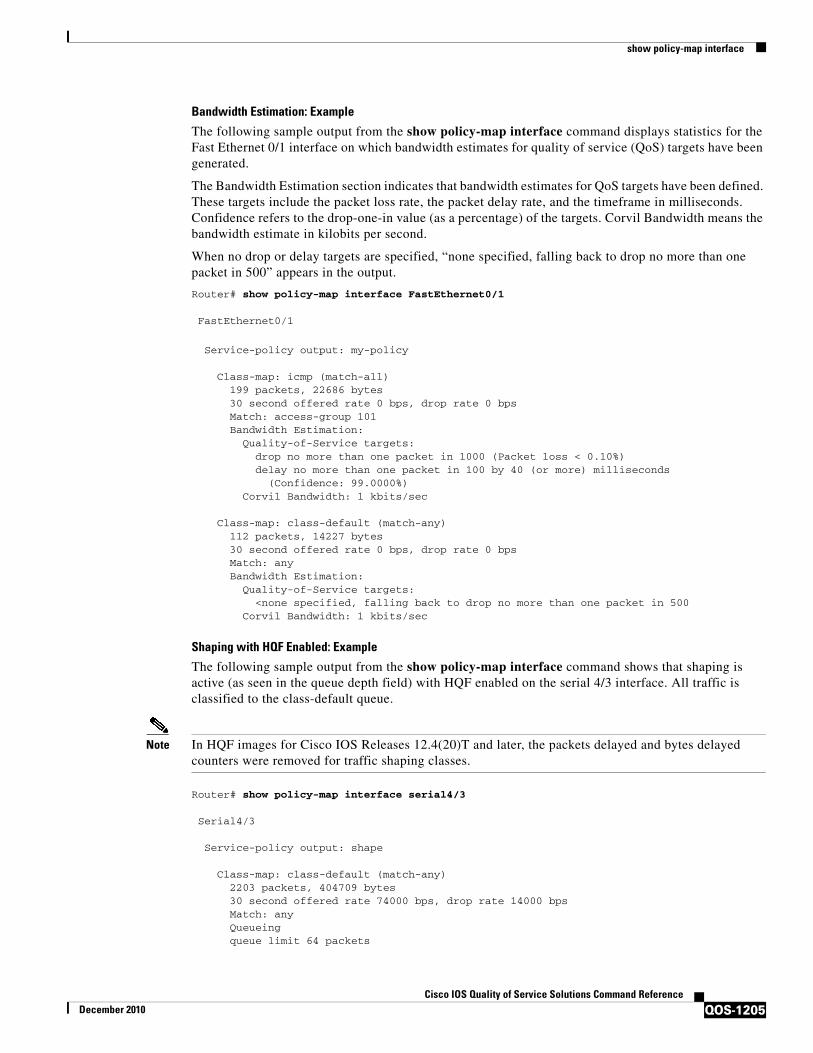
show policy-map interface
QOS-1205Cisco IOS Quality of Service Solutions Command Reference
December 2010
Bandwidth Estimation: Example
The following sample output from the show policy-map interface command displays statistics for the Fast Ethernet 0/1 interface on which bandwidth estimates for quality of service (QoS) targets have been generated.
The Bandwidth Estimation section indicates that bandwidth estimates for QoS targets have been defined. These targets include the packet loss rate, the packet delay rate, and the timeframe in milliseconds. Confidence refers to the drop-one-in value (as a percentage) of the targets. Corvil Bandwidth means the bandwidth estimate in kilobits per second.
When no drop or delay targets are specified, “none specified, falling back to drop no more than one packet in 500” appears in the output.
Router# show policy-map interface FastEthernet0/1
FastEthernet0/1
Service-policy output: my-policy
Class-map: icmp (match-all) 199 packets, 22686 bytes 30 second offered rate 0 bps, drop rate 0 bps Match: access-group 101 Bandwidth Estimation: Quality-of-Service targets: drop no more than one packet in 1000 (Packet loss < 0.10%) delay no more than one packet in 100 by 40 (or more) milliseconds (Confidence: 99.0000%) Corvil Bandwidth: 1 kbits/sec
Class-map: class-default (match-any) 112 packets, 14227 bytes 30 second offered rate 0 bps, drop rate 0 bps Match: any Bandwidth Estimation: Quality-of-Service targets: <none specified, falling back to drop no more than one packet in 500 Corvil Bandwidth: 1 kbits/sec
Shaping with HQF Enabled: Example
The following sample output from the show policy-map interface command shows that shaping is active (as seen in the queue depth field) with HQF enabled on the serial 4/3 interface. All traffic is classified to the class-default queue.
Note In HQF images for Cisco IOS Releases 12.4(20)T and later, the packets delayed and bytes delayed counters were removed for traffic shaping classes.
Router# show policy-map interface serial4/3
Serial4/3
Service-policy output: shape
Class-map: class-default (match-any) 2203 packets, 404709 bytes 30 second offered rate 74000 bps, drop rate 14000 bps Match: any Queueing queue limit 64 packets

show policy-map interface
QOS-1206Cisco IOS Quality of Service Solutions Command Reference
December 2010
(queue depth/total drops/no-buffer drops) 64/354/0 (pkts output/bytes output) 1836/337280 shape (average) cir 128000, bc 1000, be 1000 target shape rate 128000 lower bound cir 0, adapt to fecn 0
Service-policy : LLQ
queue stats for all priority classes: queue limit 64 packets (queue depth/total drops/no-buffer drops) 0/0/0 (pkts output/bytes output) 0/0
Class-map: c1 (match-all) 0 packets, 0 bytes 30 second offered rate 0 bps, drop rate 0 bps Match: ip precedence 1 Priority: 32 kbps, burst bytes 1500, b/w exceed drops: 0
Class-map: class-default (match-any) 2190 packets, 404540 bytes 30 second offered rate 74000 bps, drop rate 14000 bps Match: any
queue limit 64 packets (queue depth/total drops/no-buffer drops) 63/417/0 (pkts output/bytes output) 2094/386300
Packets Matched on the Basis of VLAN ID Number: Example
Note As of Cisco IOS Release 12.2(31)SB2, matching packets on the basis of VLAN ID numbers is supported on the Catalyst 1000 platform only.
The following is a sample configuration in which packets are matched and classified on the basis of the VLAN ID number. In this sample configuration, packets that match VLAN ID number 150 are placed in a class called “class1.”
Router# show class-map
Class Map match-all class1 (id 3)Match vlan 150
Class1 is then configured as part of the policy map called “policy1.” The policy map is attached to Fast Ethernet subinterface 0/0.1.
The following sample output of the show policy-map interface command displays the packet statistics for the policy maps attached to Fast Ethernet subinterface 0/0.1. It displays the statistics for policy1, in which class1 has been configured.
Router# show policy-map interface
FastEthernet0/0.1
! Policy-map name.Service-policy input: policy1
! Class configured in the policy map.Class-map: class1 (match-all)0 packets, 0 bytes
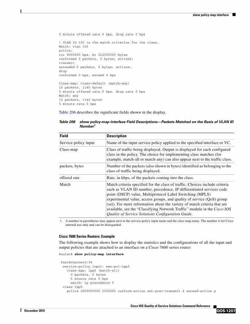
show policy-map interface
QOS-1207Cisco IOS Quality of Service Solutions Command Reference
December 2010
5 minute offered rate 0 bps, drop rate 0 bps
! VLAN ID 150 is the match criterion for the class.Match: vlan 150police:cir 8000000 bps, bc 512000000 bytesconformed 0 packets, 0 bytes; actions:transmitexceeded 0 packets, 0 bytes; actions:dropconformed 0 bps, exceed 0 bps
Class-map: class-default (match-any)10 packets, 1140 bytes5 minute offered rate 0 bps, drop rate 0 bpsMatch: any10 packets, 1140 bytes5 minute rate 0 bps
Table 206 describes the significant fields shown in the display.
Cisco 7600 Series Routers: Example
The following example shows how to display the statistics and the configurations of all the input and output policies that are attached to an interface on a Cisco 7600 series router:
Router# show policy-map interface
FastEthernet5/36 service-policy input: max-pol-ipp5 class-map: ipp5 (match-all) 0 packets, 0 bytes 5 minute rate 0 bps match: ip precedence 5 class ipp5 police 2000000000 2000000 conform-action set-prec-transmit 6 exceed-action p
Table 206 show policy-map interface Field Descriptions—Packets Matched on the Basis of VLAN ID
Number1
1. A number in parentheses may appear next to the service-policy input name and the class-map name. The number is for Cisco internal use only and can be disregarded.
Field Description
Service-policy input Name of the input service policy applied to the specified interface or VC.
Class-map Class of traffic being displayed. Output is displayed for each configured class in the policy. The choice for implementing class matches (for example, match-all or match-any) can also appear next to the traffic class.
packets, bytes Number of the packets (also shown in bytes) identified as belonging to the class of traffic being displayed.
offered rate Rate, in kbps, of the packets coming into the class.
Match Match criteria specified for the class of traffic. Choices include criteria such as VLAN ID number, precedence, IP differentiated services code point (DSCP) value, Multiprotocol Label Switching (MPLS) experimental value, access groups, and quality of service (QoS) group (set). For more information about the variety of match criteria that are available, see the “Classifying Network Traffic” module in the Cisco IOS Quality of Service Solutions Configuration Guide.

show policy-map interface
QOS-1208Cisco IOS Quality of Service Solutions Command Reference
December 2010
policed-dscp-transmit
The following example shows how to display the input-policy statistics and the configurations for a specific interface on a Cisco 7600 series router:
Router# show policy-map interface fastethernet 5/36 input
FastEthernet5/36 service-policy input: max-pol-ipp5 class-map: ipp5 (match-all) 0 packets, 0 bytes 5 minute rate 0 bps match: ip precedence 5 class ipp5 police 2000000000 2000000 conform-action set-prec-transmit 6 exceed-action ppoliced-dscp-transmit
Table 207 describes the significant fields shown in the display.
Cisco 7200 Series Routers: Example
The following example shows the automatic rounding-off of the bc and be values, in the MQC police policy-map, to the interface’s MTU size in a Cisco 7200 series router. The rounding-off is done only when the bc and be values are lesser than the interface’s MTU size.
Router# show policy-map interface
Service-policy output: p2
Service-policy output: p2
Class-map: class-default (match-any) 2 packets, 106 bytes 30 second offered rate 0000 bps, drop rate 0000 bps Match: any
Table 207 show policy-map interface Field Descriptions—Cisco 7600 Series Routers
Field Description
service-policy input Name of the input service policy applied to the specified interface.
class-map Class of traffic being displayed. Output is displayed for each configured class in the policy. The choice for implementing class matches (for example, match-all or match-any) can also appear next to the traffic class.
packets, bytes Number of the packets (also shown in bytes) identified as belonging to the class of traffic being displayed.
minute rate Rate, in kbps, of the packets coming into the class.
match Match criteria specified for the class of traffic. Choices include criteria such as VLAN ID number, precedence, IP differentiated services code point (DSCP) value, Multiprotocol Label Switching (MPLS) experimental value, access groups, and quality of service (QoS) group (set). For more information about the variety of match criteria that are available, see the “Classifying Network Traffic” module in the Cisco IOS Quality of Service Solutions Configuration Guide.
class Precedence value.
police Indicates that the police command has been configured to enable traffic policing.
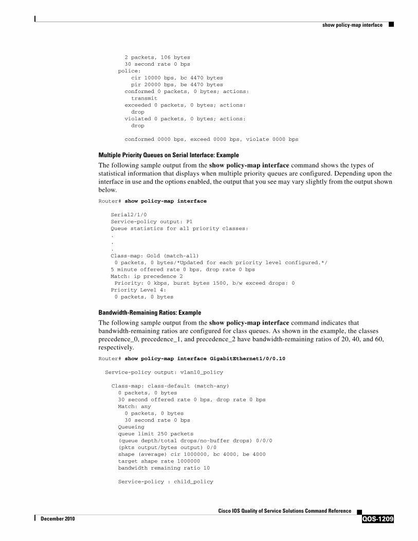
show policy-map interface
QOS-1209Cisco IOS Quality of Service Solutions Command Reference
December 2010
2 packets, 106 bytes 30 second rate 0 bps police: cir 10000 bps, bc 4470 bytes pir 20000 bps, be 4470 bytes conformed 0 packets, 0 bytes; actions: transmit exceeded 0 packets, 0 bytes; actions: drop violated 0 packets, 0 bytes; actions: drop
conformed 0000 bps, exceed 0000 bps, violate 0000 bps
Multiple Priority Queues on Serial Interface: Example
The following sample output from the show policy-map interface command shows the types of statistical information that displays when multiple priority queues are configured. Depending upon the interface in use and the options enabled, the output that you see may vary slightly from the output shown below.
Router# show policy-map interface
Serial2/1/0Service-policy output: P1Queue statistics for all priority classes:...Class-map: Gold (match-all)0 packets, 0 bytes/*Updated for each priority level configured.*/
5 minute offered rate 0 bps, drop rate 0 bpsMatch: ip precedence 2Priority: 0 kbps, burst bytes 1500, b/w exceed drops: 0
Priority Level 4:0 packets, 0 bytes
Bandwidth-Remaining Ratios: Example
The following sample output from the show policy-map interface command indicates that bandwidth-remaining ratios are configured for class queues. As shown in the example, the classes precedence_0, precedence_1, and precedence_2 have bandwidth-remaining ratios of 20, 40, and 60, respectively.
Router# show policy-map interface GigabitEthernet1/0/0.10
Service-policy output: vlan10_policy
Class-map: class-default (match-any) 0 packets, 0 bytes 30 second offered rate 0 bps, drop rate 0 bps Match: any 0 packets, 0 bytes 30 second rate 0 bps Queueing
queue limit 250 packets (queue depth/total drops/no-buffer drops) 0/0/0 (pkts output/bytes output) 0/0 shape (average) cir 1000000, bc 4000, be 4000 target shape rate 1000000 bandwidth remaining ratio 10
Service-policy : child_policy

show policy-map interface
QOS-1210Cisco IOS Quality of Service Solutions Command Reference
December 2010
Class-map: precedence_0 (match-all) 0 packets, 0 bytes 30 second offered rate 0 bps, drop rate 0 bps Match: ip precedence 0 Queueing queue limit 62 packets (queue depth/total drops/no-buffer drops) 0/0/0 (pkts output/bytes output) 0/0 shape (average) cir 500000, bc 2000, be 2000 target shape rate 500000 bandwidth remaining ratio 20
Class-map: precedence_1 (match-all) 0 packets, 0 bytes 30 second offered rate 0 bps, drop rate 0 bps Match: ip precedence 1 Queueing queue limit 62 packets (queue depth/total drops/no-buffer drops) 0/0/0 (pkts output/bytes output) 0/0 shape (average) cir 500000, bc 2000, be 2000 target shape rate 500000 bandwidth remaining ratio 40
Class-map: precedence_2 (match-all) 0 packets, 0 bytes 30 second offered rate 0 bps, drop rate 0 bps Match: ip precedence 2 Queueing queue limit 62 packets (queue depth/total drops/no-buffer drops) 0/0/0 (pkts output/bytes output) 0/0 shape (average) cir 500000, bc 2000, be 2000 target shape rate 500000 bandwidth remaining ratio 60
Class-map: class-default (match-any) 0 packets, 0 bytes 30 second offered rate 0 bps, drop rate 0 bps Match: any 0 packets, 0 bytes 30 second rate 0 bps queue limit 62 packets (queue depth/total drops/no-buffer drops) 0/0/0 (pkts output/bytes output) 0/0

show policy-map interface
QOS-1211Cisco IOS Quality of Service Solutions Command Reference
December 2010
Table 208 describes the significant fields shown in the display.
Tunnel Marking: Example
In this sample output of the show policy-map interface command, the character string “ip dscp tunnel 3” indicates that L2TPv3 tunnel marking has been configured to set the DSCP value to 3 in the header of a tunneled packet.
Router# show policy-map interface
Serial0
Service-policy input: tunnel
Class-map: frde (match-all) 0 packets, 0 bytes 30 second offered rate 0 bps, drop rate 0 bps Match: fr-de QoS Set ip dscp tunnel 3 Packets marked 0
Class-map: class-default (match-any) 13736 packets, 1714682 bytes 30 second offered rate 0 bps, drop rate 0 bps Match: any 13736 packets, 1714682 bytes 30 second rate 0 bps
Table 208 show policy-map interface Field Descriptions—Configured for Bandwidth-Remaining
Ratios
Field Description
Service-policy output Name of the output service policy applied to the specified interface.
Class-map Class of traffic being displayed. Output is displayed for each configured class in the policy. The choice for implementing class matches (for example, match-all or match-any) can also appear next to the traffic class.
packets, bytes Number of the packets (also shown in bytes) identified as belonging to the class of traffic being displayed.
bandwidth remaining ratio
Indicates the ratio used to allocate excess bandwidth.
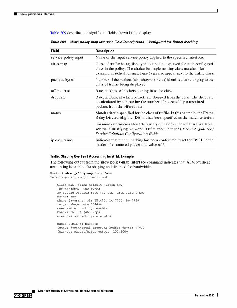
show policy-map interface
QOS-1212Cisco IOS Quality of Service Solutions Command Reference
December 2010
Table 209 describes the significant fields shown in the display.
Traffic Shaping Overhead Accounting for ATM: Example
The following output from the show policy-map interface command indicates that ATM overhead accounting is enabled for shaping and disabled for bandwidth:
Router# show policy-map interfaceService-policy output:unit-test
Class-map: class-default (match-any)100 packets, 1000 bytes30 second offered rate 800 bps, drop rate 0 bpsMatch: anyshape (average) cir 154400, bc 7720, be 7720target shape rate 154400overhead accounting: enabledbandwidth 30% (463 kbps)overhead accounting: disabled
queue limit 64 packets(queue depth/total drops/no-buffer drops) 0/0/0(packets output/bytes output) 100/1000
Table 209 show policy-map interface Field Descriptions—Configured for Tunnel Marking
Field Description
service-policy input Name of the input service policy applied to the specified interface.
class-map Class of traffic being displayed. Output is displayed for each configured class in the policy. The choice for implementing class matches (for example, match-all or match-any) can also appear next to the traffic class.
packets, bytes Number of the packets (also shown in bytes) identified as belonging to the class of traffic being displayed.
offered rate Rate, in kbps, of packets coming in to the class.
drop rate Rate, in kbps, at which packets are dropped from the class. The drop rate is calculated by subtracting the number of successfully transmitted packets from the offered rate.
match Match criteria specified for the class of traffic. In this example, the Frame Relay Discard Eligible (DE) bit has been specified as the match criterion.
For more information about the variety of match criteria that are available, see the “Classifying Network Traffic” module in the Cisco IOS Quality of Service Solutions Configuration Guide.
ip dscp tunnel Indicates that tunnel marking has been configured to set the DSCP in the header of a tunneled packet to a value of 3.

show policy-map interface
QOS-1213Cisco IOS Quality of Service Solutions Command Reference
December 2010
Table 210 describes the significant fields shown in the display.
HQF: Example
The following output from the show policy-map interface command displays the configuration for Fast Ethernet interface 0/0:
Note In HQF images for Cisco IOS Releases 12.4(20)T and later releases, the packets delayed and bytes delayed counters were removed for traffic shaping classes.
Router# show policy-map interface FastEthernet0/0
FastEthernet0/0 Service-policy output: test1 Class-map: class-default (match-any) 129 packets, 12562 bytes 30 second offered rate 0 bps, drop rate 0 bps Match: any Queueing queue limit 64 packets (queue depth/total drops/no-buffer drops) 0/0/0 (pkts output/bytes output) 129/12562
Table 210 show policy-map interface Field Descriptions—Configured for Traffic Shaping Overhead
Accounting for ATM
Field Description
service-policy output Name of the output service policy applied to the specified interface.
class-map Class of traffic being displayed. Output is displayed for each configured class in the policy. The choice for implementing class matches (for example, match-all or match-any) can also appear next to the traffic class.
packets, bytes Number of the packets (also shown in bytes) identified as belonging to the class of traffic being displayed.
offered rate Rate, in kbps, of packets coming in to the class.
drop rate Rate, in kbps, at which packets are dropped from the class. The drop rate is calculated by subtracting the number of successfully transmitted packets from the offered rate.
match Match criteria specified for the class of traffic. In this example, the Frame Relay Discard Eligible (DE) bit has been specified as the match criterion.
For more information about the variety of match criteria that are available, see the “Classifying Network Traffic” module in the Cisco IOS Quality of Service Solutions Configuration Guide.
target shape rate Indicates that traffic shaping is enabled at the specified rate.
overhead accounting Indicates whether overhead accounting is enabled or disabled for traffic shaping.
bandwidth Indicates the percentage of bandwidth allocated for traffic queueing.
overhead accounting: Indicates whether overhead accounting is enabled or disabled for traffic queueing.

show policy-map interface
QOS-1214Cisco IOS Quality of Service Solutions Command Reference
December 2010
shape (average) cir 1536000, bc 6144, be 6144 target shape rate 1536000 Service-policy : test2 queue stats for all priority classes: queue limit 64 packets (queue depth/total drops/no-buffer drops) 0/0/0 (pkts output/bytes output) 0/0 Class-map: RT (match-all) 0 packets, 0 bytes 30 second offered rate 0 bps, drop rate 0 bps Match: ip dscp ef (46) Priority: 20% (307 kbps), burst bytes 7650, b/w exceed drops: 0 Class-map: BH (match-all) 0 packets, 0 bytes 30 second offered rate 0 bps, drop rate 0 bps Match: ip dscp af41 (34) Queueing queue limit 128 packets (queue depth/total drops/no-buffer drops) 0/0/0 (pkts output/bytes output) 0/0 bandwidth 40% (614 kbps) Class-map: BL (match-all) 0 packets, 0 bytes 30 second offered rate 0 bps, drop rate 0 bps Match: ip dscp af21 (18) Queueing queue limit 64 packets (queue depth/total drops/no-buffer drops) 0/0/0 (pkts output/bytes output) 0/0 bandwidth 35% (537 kbps) Exp-weight-constant: 9 (1/512) Mean queue depth: 0 packets dscp Transmitted Random drop Tail drop Minimum Maximum Mark pkts/bytes pkts/bytes pkts/bytes thresh thresh prob af21 0/0 0/0 0/0 100 400 1/10 Class-map: class-default (match-any) 129 packets, 12562 bytes 30 second offered rate 0 bps, drop rate 0 bps Match: any queue limit 64 packets (queue depth/total drops/no-buffer drops) 0/0/0 (pkts output/bytes output) 129/12562
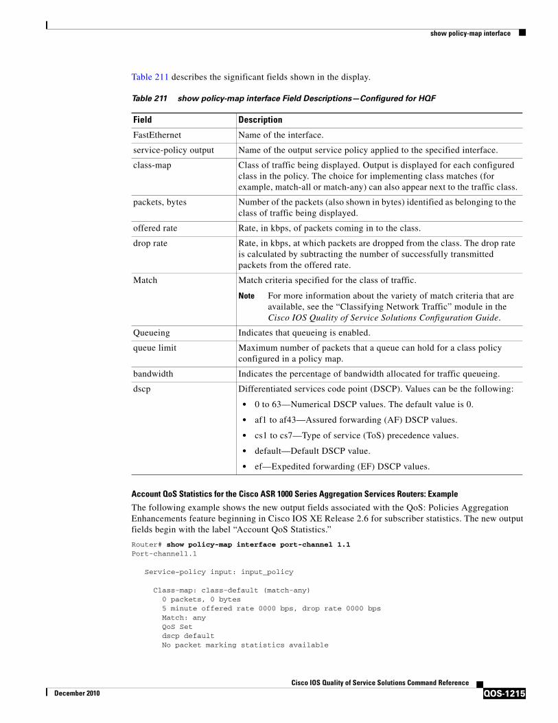
show policy-map interface
QOS-1215Cisco IOS Quality of Service Solutions Command Reference
December 2010
Table 211 describes the significant fields shown in the display.
Account QoS Statistics for the Cisco ASR 1000 Series Aggregation Services Routers: Example
The following example shows the new output fields associated with the QoS: Policies Aggregation Enhancements feature beginning in Cisco IOS XE Release 2.6 for subscriber statistics. The new output fields begin with the label “Account QoS Statistics.”
Router# show policy-map interface port-channel 1.1Port-channel1.1
Service-policy input: input_policy
Class-map: class-default (match-any) 0 packets, 0 bytes 5 minute offered rate 0000 bps, drop rate 0000 bps Match: any QoS Set dscp default No packet marking statistics available
Table 211 show policy-map interface Field Descriptions—Configured for HQF
Field Description
FastEthernet Name of the interface.
service-policy output Name of the output service policy applied to the specified interface.
class-map Class of traffic being displayed. Output is displayed for each configured class in the policy. The choice for implementing class matches (for example, match-all or match-any) can also appear next to the traffic class.
packets, bytes Number of the packets (also shown in bytes) identified as belonging to the class of traffic being displayed.
offered rate Rate, in kbps, of packets coming in to the class.
drop rate Rate, in kbps, at which packets are dropped from the class. The drop rate is calculated by subtracting the number of successfully transmitted packets from the offered rate.
Match Match criteria specified for the class of traffic.
Note For more information about the variety of match criteria that are available, see the “Classifying Network Traffic” module in the Cisco IOS Quality of Service Solutions Configuration Guide.
Queueing Indicates that queueing is enabled.
queue limit Maximum number of packets that a queue can hold for a class policy configured in a policy map.
bandwidth Indicates the percentage of bandwidth allocated for traffic queueing.
dscp Differentiated services code point (DSCP). Values can be the following:
• 0 to 63—Numerical DSCP values. The default value is 0.
• af1 to af43—Assured forwarding (AF) DSCP values.
• cs1 to cs7—Type of service (ToS) precedence values.
• default—Default DSCP value.
• ef—Expedited forwarding (EF) DSCP values.
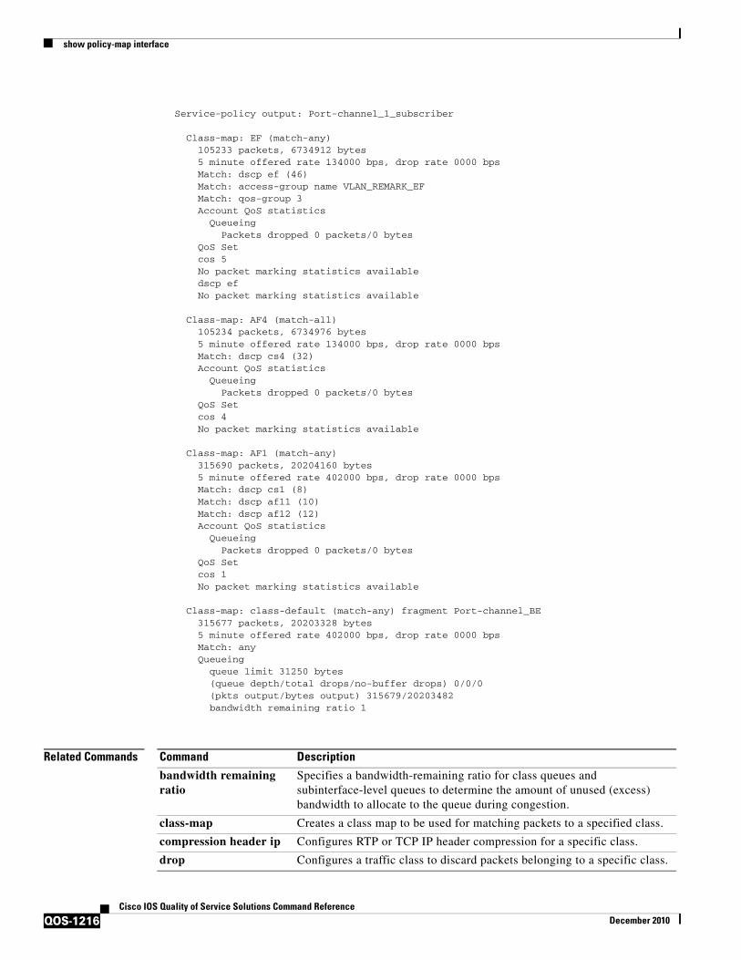
show policy-map interface
QOS-1216Cisco IOS Quality of Service Solutions Command Reference
December 2010
Service-policy output: Port-channel_1_subscriber
Class-map: EF (match-any) 105233 packets, 6734912 bytes 5 minute offered rate 134000 bps, drop rate 0000 bps Match: dscp ef (46) Match: access-group name VLAN_REMARK_EF Match: qos-group 3 Account QoS statistics
Queueing Packets dropped 0 packets/0 bytes
QoS Set cos 5 No packet marking statistics available dscp ef No packet marking statistics available
Class-map: AF4 (match-all) 105234 packets, 6734976 bytes 5 minute offered rate 134000 bps, drop rate 0000 bps Match: dscp cs4 (32) Account QoS statistics
Queueing Packets dropped 0 packets/0 bytes
QoS Set cos 4 No packet marking statistics available
Class-map: AF1 (match-any) 315690 packets, 20204160 bytes 5 minute offered rate 402000 bps, drop rate 0000 bps Match: dscp cs1 (8) Match: dscp af11 (10) Match: dscp af12 (12) Account QoS statistics
Queueing Packets dropped 0 packets/0 bytes
QoS Set cos 1 No packet marking statistics available
Class-map: class-default (match-any) fragment Port-channel_BE 315677 packets, 20203328 bytes 5 minute offered rate 402000 bps, drop rate 0000 bps Match: any Queueing
queue limit 31250 bytes (queue depth/total drops/no-buffer drops) 0/0/0 (pkts output/bytes output) 315679/20203482 bandwidth remaining ratio 1
Related Commands Command Description
bandwidth remaining ratio
Specifies a bandwidth-remaining ratio for class queues and subinterface-level queues to determine the amount of unused (excess) bandwidth to allocate to the queue during congestion.
class-map Creates a class map to be used for matching packets to a specified class.
compression header ip Configures RTP or TCP IP header compression for a specific class.
drop Configures a traffic class to discard packets belonging to a specific class.
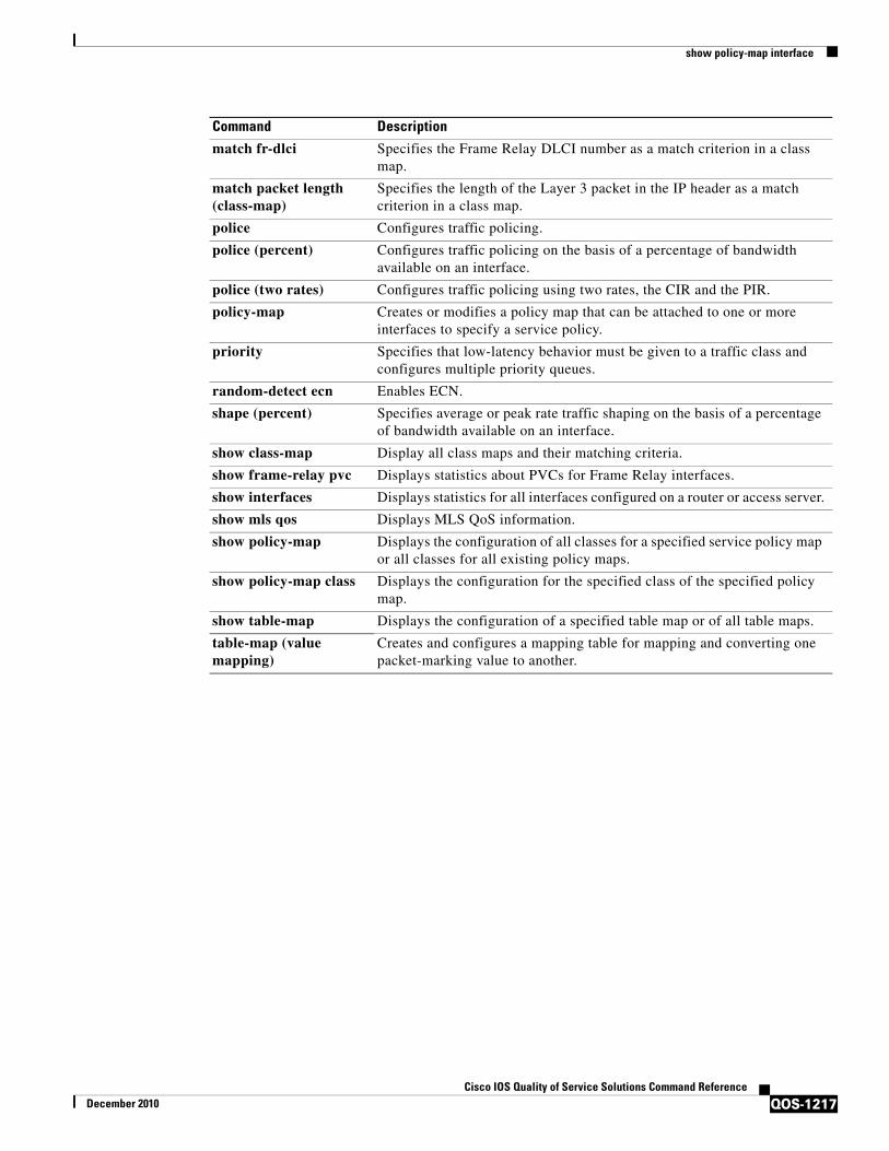
show policy-map interface
QOS-1217Cisco IOS Quality of Service Solutions Command Reference
December 2010
match fr-dlci Specifies the Frame Relay DLCI number as a match criterion in a class map.
match packet length (class-map)
Specifies the length of the Layer 3 packet in the IP header as a match criterion in a class map.
police Configures traffic policing.
police (percent) Configures traffic policing on the basis of a percentage of bandwidth available on an interface.
police (two rates) Configures traffic policing using two rates, the CIR and the PIR.
policy-map Creates or modifies a policy map that can be attached to one or more interfaces to specify a service policy.
priority Specifies that low-latency behavior must be given to a traffic class and configures multiple priority queues.
random-detect ecn Enables ECN.
shape (percent) Specifies average or peak rate traffic shaping on the basis of a percentage of bandwidth available on an interface.
show class-map Display all class maps and their matching criteria.
show frame-relay pvc Displays statistics about PVCs for Frame Relay interfaces.
show interfaces Displays statistics for all interfaces configured on a router or access server.
show mls qos Displays MLS QoS information.
show policy-map Displays the configuration of all classes for a specified service policy map or all classes for all existing policy maps.
show policy-map class Displays the configuration for the specified class of the specified policy map.
show table-map Displays the configuration of a specified table map or of all table maps.
table-map (value mapping)
Creates and configures a mapping table for mapping and converting one packet-marking value to another.
Command Description

show policy-map interface brief
QOS-1218Cisco IOS Quality of Service Solutions Command Reference
December 2010
show policy-map interface briefTo display information about only the active policy maps attached to an interface, use the show policy-map interface brief command in privileged EXEC mode.
show policy-map interface [input | output] brief [policy-map-name] [vrf [vrf-id]] [timestamp]
Syntax Description
Command Default If no optional keywords or arguments are specified, all policy maps (even those that are not active) are displayed.
Command Modes Privileged EXEC (#)
Command History
Usage Guidelines The show policy-map interface brief command displays the name of the active policy maps and the interfaces to which those policy maps are attached. An active policy map is one that is attached to an interface.
The optional keywords and arguments allow you to tailor the information displayed about VPNs, time stamps, and user IDs.
If you do not specify any optional keywords or arguments, all policy maps (even those that are not active) are displayed.
input (Optional) Indicates that only the information about the active input policy maps will be displayed.
output (Optional) Indicates that only the information about the active output policy maps will be displayed.
brief Indicates that the name of all the active policy maps (both input and output policy maps) and the interfaces to which the policy maps are attached will be displayed. The active input policy maps will be displayed first, followed by the output policy maps.
policy-map-name (Optional) Name of an active policy map to be displayed.
vrf (Optional) Indicates that the active policy maps for Virtual Private Network (VPN) routing and forwarding (VRF) instances will be displayed.
vrf-id (Optional) A specific VRF identifier.
timestamp (Optional) Indicates that the date and time when the policy map was attached will be displayed, along with the ID of the user who attached the policy map.
Release Modification
12.2(28)SB This command was introduced.
12.2(33)SRB This command was integrated into Cisco IOS Release 12.2(33)SRB.
12.2(33)SXH This command was integrated into Cisco IOS Release 12.2(33)SXH.
12.4(20)T This command was integrated into Cisco IOS Release 12.4(20)T.

show policy-map interface brief
QOS-1219Cisco IOS Quality of Service Solutions Command Reference
December 2010
VPN Information Reported
The show policy-map interface brief command can be used for VRF interfaces in applications that use VPNs. To specify VRF interfaces, use the vrf keyword with the vrf-id argument.
Time-stamp and User ID Information Reported
If the optional timestamp keyword is used with the show policy-map interface brief command, the time and date when a policy map was attached to an interface appear in the display. In addition to the time and date information, the name (that is, the user ID) of the person who attached the policy map to the interface will be displayed.
Note If the network software is reloaded (reinstalled), the time-stamp information (the time and date information) obtained will not be retained for any of the policy maps attached to interfaces on the network. Instead, the time and date information displayed will be the time and date when the software was reloaded.
Method for Obtaining User Information
The user information included in the display is obtained from the information that you enter when you log in to the router. For example, if you are using the SSH Secure Shell utility to log in to a router, you would typically enter your username and password. However, it is not always possible to obtain the user information. Instances where user information cannot be obtained include the following:
• Not all routers require user information when you log in. Therefore, you may not be prompted to enter your username when you log in to a router.
• If you are connecting to a console port using the Telnet utility in a DOS environment, you do not need to enter user information.
• The user information cannot be retrieved because of system constraints or other factors.
If the user information cannot be obtained, the words “by unknown” will be displayed.
Hierarchical Policy Map Information
For a hierarchical policy map structure, only the information about the parent policy maps is displayed. Information about child policy maps is not displayed.
ATM PVCs
For ATM permanent virtual circuits (PVCs), policy maps do not remain associated with the interface if the ATM PVC is not working properly (that is, the ATM PVC is “down”). Therefore, if an ATM PVC is down, and a policy map is attached to an interface, the show policy-map interface brief command does not include information about the policy maps in the command output.
Examples The information that is displayed by the show policy-map interface brief command varies according to the optional keywords and arguments that you specify.
The following sections list the significant keyword and argument combinations used with the command and describe the corresponding information displayed.
show policy-map interface brief Command Example
The show policy-map interface brief command displays all the attached policy maps (both input policy maps and output policy maps) along with the information about the interfaces to which the policy maps are attached. The input policy maps are displayed first, followed by the output policy maps.
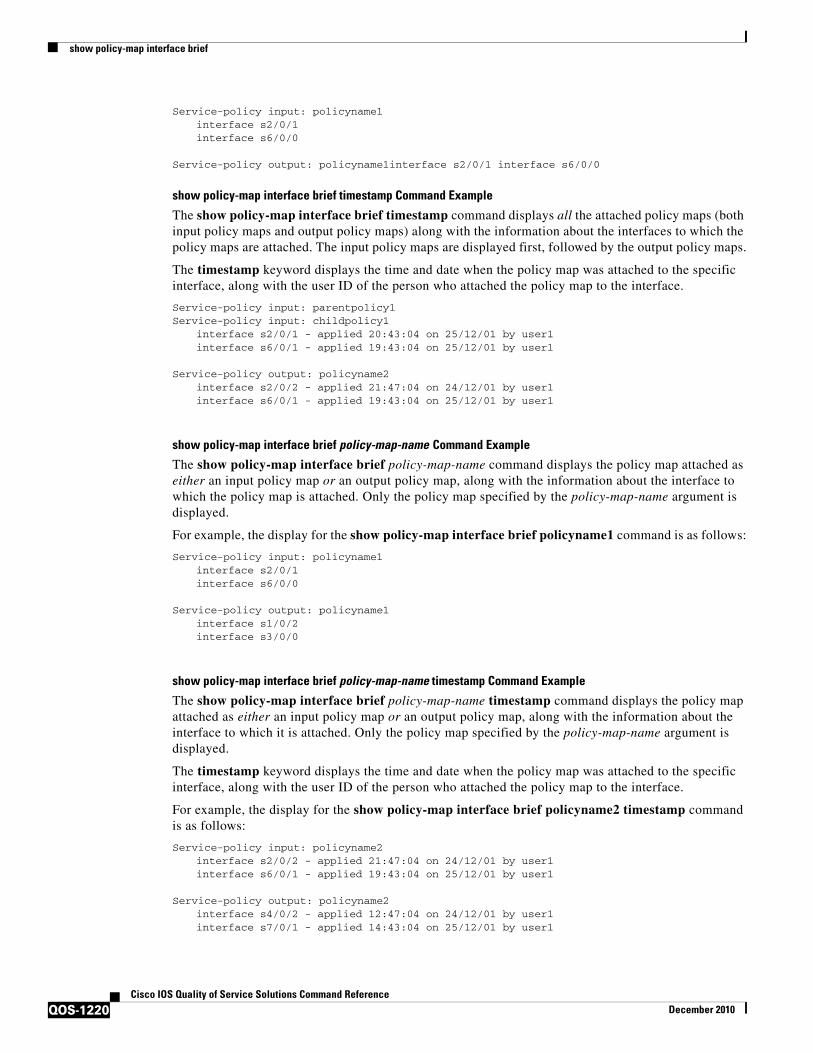
show policy-map interface brief
QOS-1220Cisco IOS Quality of Service Solutions Command Reference
December 2010
Service-policy input: policyname1interface s2/0/1 interface s6/0/0
Service-policy output: policyname1interface s2/0/1 interface s6/0/0
show policy-map interface brief timestamp Command Example
The show policy-map interface brief timestamp command displays all the attached policy maps (both input policy maps and output policy maps) along with the information about the interfaces to which the policy maps are attached. The input policy maps are displayed first, followed by the output policy maps.
The timestamp keyword displays the time and date when the policy map was attached to the specific interface, along with the user ID of the person who attached the policy map to the interface.
Service-policy input: parentpolicy1 Service-policy input: childpolicy1
interface s2/0/1 - applied 20:43:04 on 25/12/01 by user1interface s6/0/1 - applied 19:43:04 on 25/12/01 by user1
Service-policy output: policyname2interface s2/0/2 - applied 21:47:04 on 24/12/01 by user1interface s6/0/1 - applied 19:43:04 on 25/12/01 by user1
show policy-map interface brief policy-map-name Command Example
The show policy-map interface brief policy-map-name command displays the policy map attached as either an input policy map or an output policy map, along with the information about the interface to which the policy map is attached. Only the policy map specified by the policy-map-name argument is displayed.
For example, the display for the show policy-map interface brief policyname1 command is as follows:
Service-policy input: policyname1interface s2/0/1interface s6/0/0
Service-policy output: policyname1interface s1/0/2interface s3/0/0
show policy-map interface brief policy-map-name timestamp Command Example
The show policy-map interface brief policy-map-name timestamp command displays the policy map attached as either an input policy map or an output policy map, along with the information about the interface to which it is attached. Only the policy map specified by the policy-map-name argument is displayed.
The timestamp keyword displays the time and date when the policy map was attached to the specific interface, along with the user ID of the person who attached the policy map to the interface.
For example, the display for the show policy-map interface brief policyname2 timestamp command is as follows:
Service-policy input: policyname2interface s2/0/2 - applied 21:47:04 on 24/12/01 by user1interface s6/0/1 - applied 19:43:04 on 25/12/01 by user1
Service-policy output: policyname2interface s4/0/2 - applied 12:47:04 on 24/12/01 by user1interface s7/0/1 - applied 14:43:04 on 25/12/01 by user1
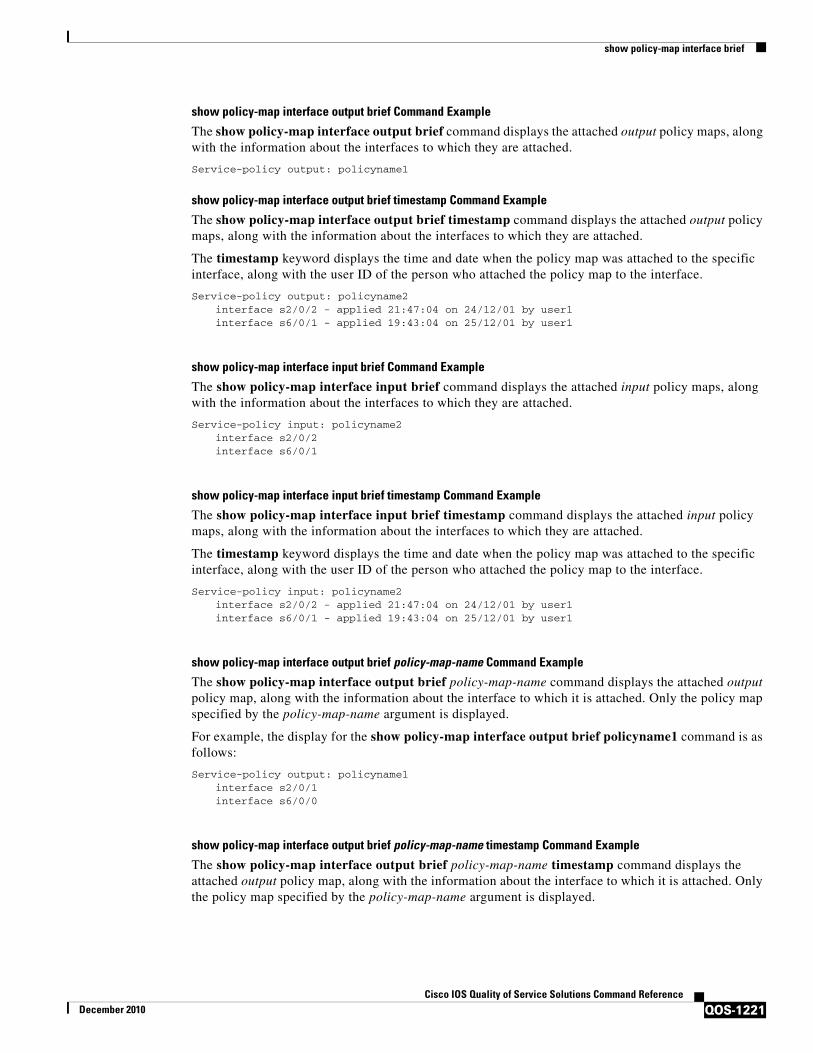
show policy-map interface brief
QOS-1221Cisco IOS Quality of Service Solutions Command Reference
December 2010
show policy-map interface output brief Command Example
The show policy-map interface output brief command displays the attached output policy maps, along with the information about the interfaces to which they are attached.
Service-policy output: policyname1
show policy-map interface output brief timestamp Command Example
The show policy-map interface output brief timestamp command displays the attached output policy maps, along with the information about the interfaces to which they are attached.
The timestamp keyword displays the time and date when the policy map was attached to the specific interface, along with the user ID of the person who attached the policy map to the interface.
Service-policy output: policyname2interface s2/0/2 - applied 21:47:04 on 24/12/01 by user1interface s6/0/1 - applied 19:43:04 on 25/12/01 by user1
show policy-map interface input brief Command Example
The show policy-map interface input brief command displays the attached input policy maps, along with the information about the interfaces to which they are attached.
Service-policy input: policyname2interface s2/0/2 interface s6/0/1
show policy-map interface input brief timestamp Command Example
The show policy-map interface input brief timestamp command displays the attached input policy maps, along with the information about the interfaces to which they are attached.
The timestamp keyword displays the time and date when the policy map was attached to the specific interface, along with the user ID of the person who attached the policy map to the interface.
Service-policy input: policyname2interface s2/0/2 - applied 21:47:04 on 24/12/01 by user1interface s6/0/1 - applied 19:43:04 on 25/12/01 by user1
show policy-map interface output brief policy-map-name Command Example
The show policy-map interface output brief policy-map-name command displays the attached output policy map, along with the information about the interface to which it is attached. Only the policy map specified by the policy-map-name argument is displayed.
For example, the display for the show policy-map interface output brief policyname1 command is as follows:
Service-policy output: policyname1interface s2/0/1interface s6/0/0
show policy-map interface output brief policy-map-name timestamp Command Example
The show policy-map interface output brief policy-map-name timestamp command displays the attached output policy map, along with the information about the interface to which it is attached. Only the policy map specified by the policy-map-name argument is displayed.

show policy-map interface brief
QOS-1222Cisco IOS Quality of Service Solutions Command Reference
December 2010
The timestamp keyword displays the time and date when the policy map was attached to the specific interface, along with the user ID of the person who attached the policy map to the interface.
For example, the display for the show policy-map interface output brief policyname2 timestamp command is as follows:
Service-policy output: policyname2interface s2/0/2 - applied 21:47:04 on 24/12/01 by user1interface s6/0/1 - applied 19:43:04 on 25/12/01 by user1
show policy-map interface input brief policy-map-name Command Example
The show policy-map interface input brief policy-map-name command displays the attached input policy map, along with the information about the interface to which it is attached. Only the policy map specified by the policy-map-name argument is displayed.
For example, the display for the show policy-map interface input brief policyname1 command is as follows:
Service-policy input: policyname1interface s2/0/1interface s6/0/0
show policy-map interface input brief policy-map-name timestamp Command Example
The show policy-map interface input brief policy-map-name timestamp command displays the attached input policy map, along with the information about the interface to which it is attached. Only the policy map specified by the policy-map-name argument is displayed.
The timestamp keyword displays the time and date when the policy map was attached to the specific interface, along with the user ID of the person who attached the policy map to the interface.
For example, the display for the show policy-map interface input brief policyname2 timestamp command is as follows:
Service-policy input: policyname2interface s2/0/2 - applied 21:47:04 on 24/12/01 by user1interface s6/0/1 - applied 19:43:04 on 25/12/01 by user1
show policy-map interface brief vrf Command Example
The show policy-map interface brief vrf command displays all the policy maps (both input policy maps and output policy maps), along with information about the interfaces and the VRFs to which the policy maps are attached.
Service-policy input: policyname1VRFA interface s2/0/1 VRFB interface s6/0/0
Service-policy output: policyname2VRFC interface s2/0/2 VRFB interface s6/0/1
show policy-map interface brief vrf timestamp Command Example
The show policy-map interface brief vrf timestamp command displays all the policy maps (both input policy maps and output policy maps), along with information about the interfaces and the VRFs to which the policy maps are attached.
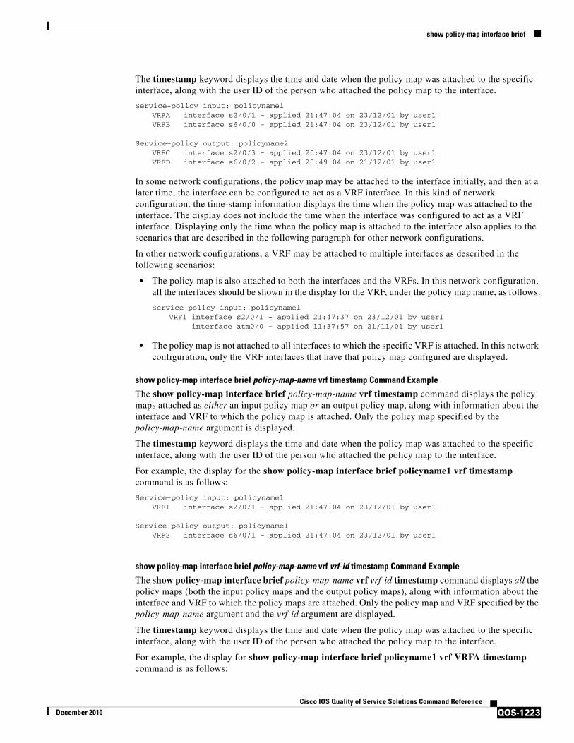
show policy-map interface brief
QOS-1223Cisco IOS Quality of Service Solutions Command Reference
December 2010
The timestamp keyword displays the time and date when the policy map was attached to the specific interface, along with the user ID of the person who attached the policy map to the interface.
Service-policy input: policyname1VRFA interface s2/0/1 - applied 21:47:04 on 23/12/01 by user1VRFB interface s6/0/0 - applied 21:47:04 on 23/12/01 by user1
Service-policy output: policyname2VRFC interface s2/0/3 - applied 20:47:04 on 23/12/01 by user1VRFD interface s6/0/2 - applied 20:49:04 on 21/12/01 by user1
In some network configurations, the policy map may be attached to the interface initially, and then at a later time, the interface can be configured to act as a VRF interface. In this kind of network configuration, the time-stamp information displays the time when the policy map was attached to the interface. The display does not include the time when the interface was configured to act as a VRF interface. Displaying only the time when the policy map is attached to the interface also applies to the scenarios that are described in the following paragraph for other network configurations.
In other network configurations, a VRF may be attached to multiple interfaces as described in the following scenarios:
• The policy map is also attached to both the interfaces and the VRFs. In this network configuration, all the interfaces should be shown in the display for the VRF, under the policy map name, as follows:
Service-policy input: policyname1VRF1 interface s2/0/1 - applied 21:47:37 on 23/12/01 by user1
interface atm0/0 - applied 11:37:57 on 21/11/01 by user1
• The policy map is not attached to all interfaces to which the specific VRF is attached. In this network configuration, only the VRF interfaces that have that policy map configured are displayed.
show policy-map interface brief policy-map-name vrf timestamp Command Example
The show policy-map interface brief policy-map-name vrf timestamp command displays the policy maps attached as either an input policy map or an output policy map, along with information about the interface and VRF to which the policy map is attached. Only the policy map specified by the policy-map-name argument is displayed.
The timestamp keyword displays the time and date when the policy map was attached to the specific interface, along with the user ID of the person who attached the policy map to the interface.
For example, the display for the show policy-map interface brief policyname1 vrf timestamp command is as follows:
Service-policy input: policyname1VRF1 interface s2/0/1 - applied 21:47:04 on 23/12/01 by user1
Service-policy output: policyname1VRF2 interface s6/0/1 - applied 21:47:04 on 23/12/01 by user1
show policy-map interface brief policy-map-name vrf vrf-id timestamp Command Example
The show policy-map interface brief policy-map-name vrf vrf-id timestamp command displays all the policy maps (both the input policy maps and the output policy maps), along with information about the interface and VRF to which the policy maps are attached. Only the policy map and VRF specified by the policy-map-name argument and the vrf-id argument are displayed.
The timestamp keyword displays the time and date when the policy map was attached to the specific interface, along with the user ID of the person who attached the policy map to the interface.
For example, the display for show policy-map interface brief policyname1 vrf VRFA timestamp command is as follows:

show policy-map interface brief
QOS-1224Cisco IOS Quality of Service Solutions Command Reference
December 2010
Service-policy input: policyname1VRFA interface s2/0/1 - applied 21:47:04 on 23/12/01 by user1
Service-policy output: policyname1VRFA interface s6/0/1 - applied 21:47:04 on 23/12/01 by user1
show policy-map interface output brief vrf Command Example
The show policy-map interface output brief vrf command displays the attached output policy maps, along with information about the interface and VRF to which the policy maps are attached.
Service-policy output: policyname2VRFC interface s2/0/2VRFA interface s6/0/1
show policy-map interface output brief vrf timestamp Command Example
The show policy-map interface output brief vrf timestamp command displays the attached output policy maps, along with information about the interface and VRF to which the policy maps are attached.
The timestamp keyword displays the time and date when the policy map was attached to the specific interface, along with the user ID of the person who attached the policy map to the interface.
Service-policy output: policyname2VRFC interface s2/0/2 - applied 21:47:04 on 23/12/01 by user1VRFA interface s6/0/1 - applied 21:47:04 on 23/12/01 by user1
show policy-map interface input brief vrf Command Example
The show policy-map interface input brief vrf command displays the attached input policy maps, along with information about the interface and VRF to which the policy maps are attached.
Service-policy input: policyname1VRFA interface s2/0/1 VRFB interface s6/0/0
Service-policy input: policyname2VRFC interface s2/0/2 VRFB interface s6/0/1
show policy-map interface input brief vrf timestamp Command Example
The show policy-map interface input brief vrf timestamp command displays the attached input policy maps, along with information about the interface and VRF to which the policy maps are attached.
The timestamp keyword displays the time and date when the policy map was attached to the specific interface, along with the user ID of the person who attached the policy map to the interface.
Service-policy input: policyname1VRFA interface s2/0/1 - applied 21:47:04 on 23/12/01 by user1VRFB interface s6/0/0 - applied 21:47:04 on 23/12/01 by user1
Service-policy input: policyname2VRFC interface s2/0/3 - applied 20:47:04 on 23/12/01 by user1VRFD interface s6/0/2 - applied 20:49:04 on 21/12/01 by user1
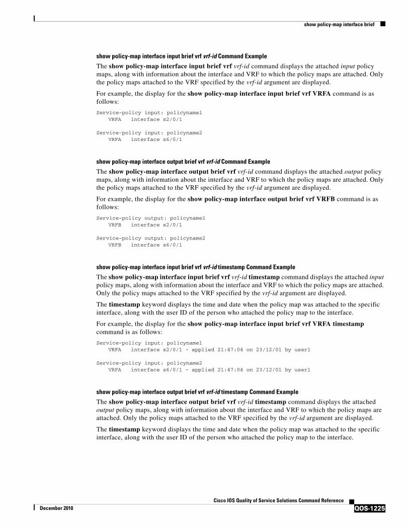
show policy-map interface brief
QOS-1225Cisco IOS Quality of Service Solutions Command Reference
December 2010
show policy-map interface input brief vrf vrf-id Command Example
The show policy-map interface input brief vrf vrf-id command displays the attached input policy maps, along with information about the interface and VRF to which the policy maps are attached. Only the policy maps attached to the VRF specified by the vrf-id argument are displayed.
For example, the display for the show policy-map interface input brief vrf VRFA command is as follows:
Service-policy input: policyname1VRFA interface s2/0/1
Service-policy input: policyname2VRFA interface s6/0/1
show policy-map interface output brief vrf vrf-id Command Example
The show policy-map interface output brief vrf vrf-id command displays the attached output policy maps, along with information about the interface and VRF to which the policy maps are attached. Only the policy maps attached to the VRF specified by the vrf-id argument are displayed.
For example, the display for the show policy-map interface output brief vrf VRFB command is as follows:
Service-policy output: policyname1VRFB interface s2/0/1
Service-policy output: policyname2VRFB interface s6/0/1
show policy-map interface input brief vrf vrf-id timestamp Command Example
The show policy-map interface input brief vrf vrf-id timestamp command displays the attached input policy maps, along with information about the interface and VRF to which the policy maps are attached. Only the policy maps attached to the VRF specified by the vrf-id argument are displayed.
The timestamp keyword displays the time and date when the policy map was attached to the specific interface, along with the user ID of the person who attached the policy map to the interface.
For example, the display for the show policy-map interface input brief vrf VRFA timestamp command is as follows:
Service-policy input: policyname1VRFA interface s2/0/1 - applied 21:47:04 on 23/12/01 by user1
Service-policy input: policyname2VRFA interface s6/0/1 - applied 21:47:04 on 23/12/01 by user1
show policy-map interface output brief vrf vrf-id timestamp Command Example
The show policy-map interface output brief vrf vrf-id timestamp command displays the attached output policy maps, along with information about the interface and VRF to which the policy maps are attached. Only the policy maps attached to the VRF specified by the vrf-id argument are displayed.
The timestamp keyword displays the time and date when the policy map was attached to the specific interface, along with the user ID of the person who attached the policy map to the interface.

show policy-map interface brief
QOS-1226Cisco IOS Quality of Service Solutions Command Reference
December 2010
For example, the display for the show policy-map interface output brief vrf VRFB timestamp command is as follows:
Service-policy output: policyname1VRFB interface s2/0/1 - applied 21:47:04 on 23/12/01 by user1
Service-policy output: policyname2VRFB interface s6/0/1 - applied 21:47:04 on 23/12/01 by user1
Table 212 describes the significant fields shown in the various displays.
Related Commands
Table 212 show policy-map interface brief Field Descriptions
Field Description
Service-policy output: policyname2
Output policy map name.
Service-policy input: policyname2
Input policy map name.
interface s2/0/1 Interface to which the policy map is attached.
VRFA VRF to which the policy map is attached.
applied 21:47:04 on 23/12/01
Time and date when the policy map was attached to the interface or VRF.
by user1 User ID of the person who attached the policy map to the interface or VRF.
Command Description
show policy-map interface
Displays the packet statistics of all classes that are configured for all service policies either on the specified interface or subinterface or on a specific PVC on the interface.

show policy-map interface service group
QOS-1227Cisco IOS Quality of Service Solutions Command Reference
December 2010
show policy-map interface service groupTo display the policy-map information for service groups that have members attached to an interface, use the show policy-map interface service group command in privileged EXEC mode.
show policy-map interface type number service group [service-group-identifier]
Syntax Description
Command Default If a service group number is not specified, policy-map information for all service groups is displayed.
Command Modes Privileged EXEC (#)
Command History
Usage Guidelines Use the show policy-map interface service group command to display information about one or more service groups with members that are attached to an interface or port-channel. The information displayed includes the policy maps attached to the interface or port-channel, the QoS features configured in those policy maps (for example, traffic policing or traffic queueing), and the corresponding packet statistics. Before using this command, the policy maps and service groups must be created.
Examples The following is an example of the show policy-map interface service group command. In this example, service group 1 is specified. Service group 1 contains two policy maps (service policies), policy1 and policy2. Traffic policing is enabled in the policy1 policy map. Traffic queueing is enabled in the policy2 policy map.
Router# show policy-map interface gigabitEthernet 9/5 service group 1 GigabitEthernet9/5: Service Group 1 Service-policy input: policy1 Class-map: class-default (match-any) 0 packets, 0 bytes 5 minute offered rate 0000 bps, drop rate 0000 bps Match: any police: cir 200000 bps, bc 6250 bytes conformed 0 packets, 0 bytes; actions:
type Interface type. For more information, use the question mark (?) online help function.
number Interface number. For more information about the numbering syntax for your networking device, use the question mark (?) online help function.
service-group-identifier (Optional) Service-group number. Enter the number of an existing service group
Release Modification
12.2(33)SRE This command was introduced.
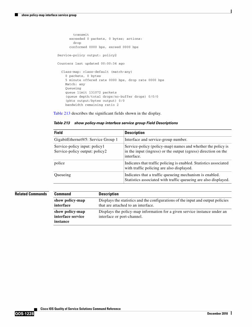
show policy-map interface service group
QOS-1228Cisco IOS Quality of Service Solutions Command Reference
December 2010
transmit exceeded 0 packets, 0 bytes; actions: drop conformed 0000 bps, exceed 0000 bps Service-policy output: policy2 Counters last updated 00:00:34 ago Class-map: class-default (match-any) 0 packets, 0 bytes 5 minute offered rate 0000 bps, drop rate 0000 bps Match: any Queueing queue limit 131072 packets (queue depth/total drops/no-buffer drops) 0/0/0 (pkts output/bytes output) 0/0 bandwidth remaining ratio 2
Table 213 describes the significant fields shown in the display.
Related Commands
Table 213 show policy-map interface service group Field Descriptions
Field Description
GigabitEthernet9/5: Service Group 1 Interface and service-group number.
Service-policy input: policy1Service-policy output: policy2
Service-policy (policy-map) names and whether the policy is in the input (ingress) or the output (egress) direction on the interface.
police Indicates that traffic policing is enabled. Statistics associated with traffic policing are also displayed.
Queueing Indicates that a traffic queueing mechanism is enabled. Statistics associated with traffic queueing are also displayed.
Command Description
show policy-map interface
Displays the statistics and the configurations of the input and output policies that are attached to an interface.
show policy-map interface service instance
Displays the policy-map information for a given service instance under an interface or port-channel.
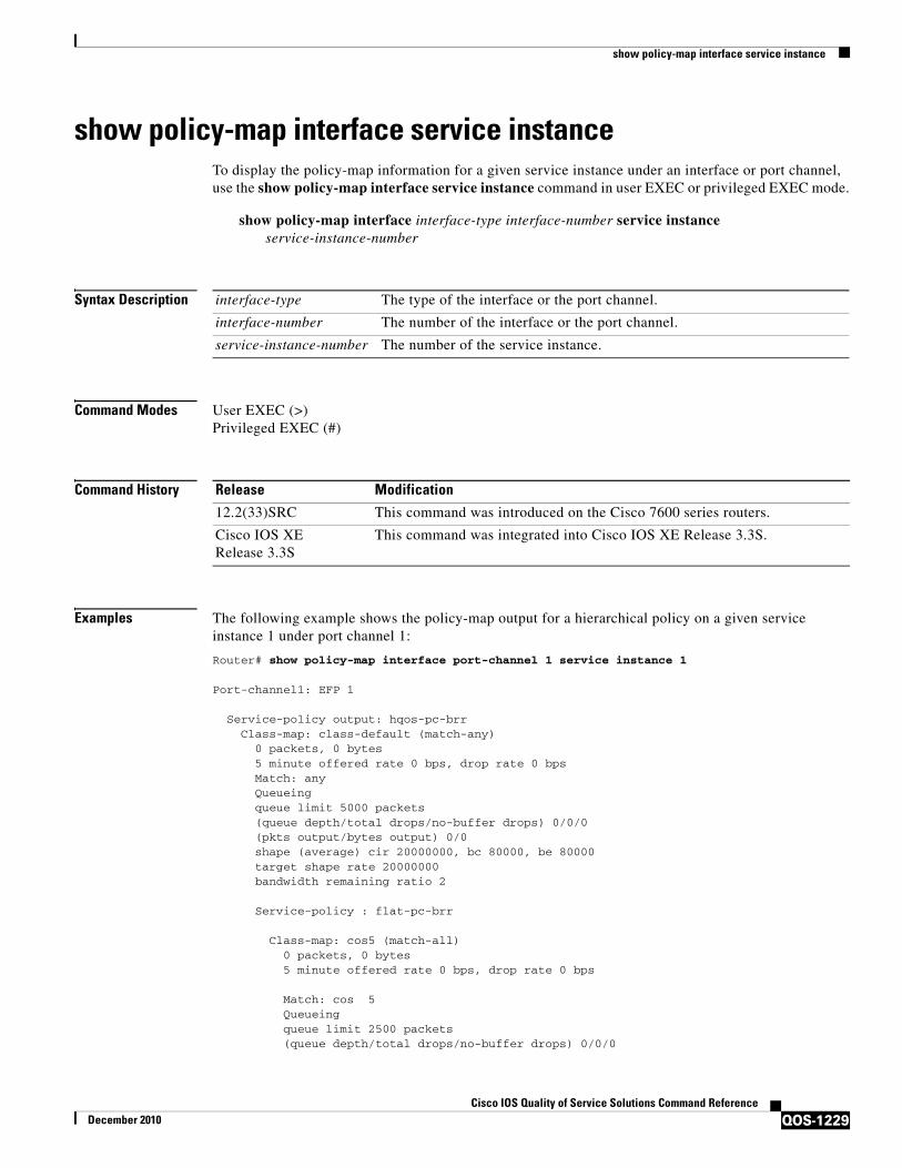
show policy-map interface service instance
QOS-1229Cisco IOS Quality of Service Solutions Command Reference
December 2010
show policy-map interface service instanceTo display the policy-map information for a given service instance under an interface or port channel, use the show policy-map interface service instance command in user EXEC or privileged EXEC mode.
show policy-map interface interface-type interface-number service instance service-instance-number
Syntax Description
Command Modes User EXEC (>)Privileged EXEC (#)
Command History
Examples The following example shows the policy-map output for a hierarchical policy on a given service instance 1 under port channel 1:
Router# show policy-map interface port-channel 1 service instance 1
Port-channel1: EFP 1
Service-policy output: hqos-pc-brr Class-map: class-default (match-any) 0 packets, 0 bytes 5 minute offered rate 0 bps, drop rate 0 bps Match: any Queueing queue limit 5000 packets (queue depth/total drops/no-buffer drops) 0/0/0 (pkts output/bytes output) 0/0 shape (average) cir 20000000, bc 80000, be 80000 target shape rate 20000000 bandwidth remaining ratio 2
Service-policy : flat-pc-brr
Class-map: cos5 (match-all) 0 packets, 0 bytes 5 minute offered rate 0 bps, drop rate 0 bps Match: cos 5 Queueing queue limit 2500 packets (queue depth/total drops/no-buffer drops) 0/0/0
interface-type The type of the interface or the port channel.
interface-number The number of the interface or the port channel.
service-instance-number The number of the service instance.
Release Modification
12.2(33)SRC This command was introduced on the Cisco 7600 series routers.
Cisco IOS XERelease 3.3S
This command was integrated into Cisco IOS XE Release 3.3S.

show policy-map interface service instance
QOS-1230Cisco IOS Quality of Service Solutions Command Reference
December 2010
(pkts output/bytes output) 0/0 shape (average) cir 10000000, bc 40000, be 40000 target shape rate 10000000
Class-map: class-default (match-any) 0 packets, 0 bytes 5 minute offered rate 0 bps, drop rate 0 bps Match: any Queueing queue limit 2500 packets (queue depth/total drops/no-buffer drops) 0/0/0 (pkts output/bytes output) 0/0 shape (average) cir 10000000, bc 40000, be 40000 target shape rate 10000000
Table 214 describes the significant fields shown in the display.
Table 214 show policy-map interface service instance Field Descriptions1
Field Description
Fields Associated with Classes or Service Policies
Service-policy output Name of the output service policy applied to the specified interface or VC.
Class-map Class of traffic being displayed. Output is displayed for each configured class in the policy. The choice for implementing class matches (for example, match-all or match-any) can also appear next to the traffic class.
packets and bytes Number of packets (also shown in bytes) identified as belonging to the class of traffic being displayed.
offered rate Rate, in kbps, of packets coming in to the class.
Note If the packets are compressed over an outgoing interface, the improved packet rate achieved by packet compression is not reflected in the offered rate. Also, if the packets are classified before they enter a combination of tunnels (for example, a generic routing encapsulation (GRE) tunnel and an IP Security (IPSec) tunnel), the offered rate does not include all the extra overhead associated with tunnel encapsulation in general. Depending on the configuration, the offered rate may include no overhead, may include the overhead for only one tunnel encapsulation, or may include the overhead for all tunnel encapsulations. In most of the GRE and IPSec tunnel configurations, the offered rate includes the overhead for GRE tunnel encapsulation only.
drop rate Rate, in kbps, at which packets are dropped from the class. The drop rate is calculated by subtracting the number of successfully transmitted packets from the offered rate.
Match Match criteria specified for the class of traffic. Choices include criteria such as IP precedence, IP differentiated services code point (DSCP) value, Multiprotocol Label Switching (MPLS) experimental (EXP) value, access groups, and QoS groups. For more information about the variety of match criteria that are available, see the “Classifying Network Traffic” module in the Cisco IOS Quality of Service Solutions Configuration Guide.

show policy-map interface service instance
QOS-1231Cisco IOS Quality of Service Solutions Command Reference
December 2010
Fields Associated with Queueing (if Enabled)
Output Queue The weighted fair queueing (WFQ) conversation to which this class of traffic is allocated.
Bandwidth Bandwidth, in either kbps or percentage, configured for this class and the burst size.
pkts matched/bytes matched
Number of packets (also shown in bytes) matching this class that were placed in the queue. This number reflects the total number of matching packets queued at any time. Packets matching this class are queued only when congestion exists. If packets match the class but are never queued because the network was not congested, those packets are not included in this total. However, if process switching is in use, the number of packets is always incremented even if the network is not congested.
depth/total drops/no-buffer drops
Number of packets discarded for this class. No-buffer indicates that no memory buffer exists to service the packet.
Fields Associated with Weighted Random Early Detection (WRED) (if Enabled)
exponential weight Exponent used in the average queue size calculation for a WRED parameter group.
mean queue depth Average queue depth based on the actual queue depth on the interface and the exponential weighting constant. It is a fluctuating average. The minimum and maximum thresholds are compared against this value to determine drop decisions.
class IP precedence level.
Transmitted pkts/bytes Number of packets (also shown in bytes) passed through WRED and not dropped by WRED.
Note If there is insufficient memory in the buffer to accommodate the packet, the packet can be dropped after the packet passes through WRED. Packets dropped because of insufficient memory in the buffer (sometimes referred to as “no-buffer drops”) are not taken into account by the WRED packet counter.
Random drop pkts/bytes Number of packets (also shown in bytes) randomly dropped when the mean queue depth is between the minimum threshold value and the maximum threshold value for the specified IP precedence level.
Tail drop pkts/bytes Number of packets dropped when the mean queue depth is greater than the maximum threshold value for the specified IP precedence level.
Minimum thresh Minimum threshold. Minimum WRED threshold in number of packets.
Maximum thresh Maximum threshold. Maximum WRED threshold in number of packets.
Mark prob Mark probability. Fraction of packets dropped when the average queue depth is at the maximum threshold.
Table 214 show policy-map interface service instance Field Descriptions1 (continued)
Field Description

show policy-map interface service instance
QOS-1232Cisco IOS Quality of Service Solutions Command Reference
December 2010
Related Commands
Fields Associated with Traffic Shaping (if Enabled)
Target Rate Rate used for shaping traffic.
Byte Limit Maximum number of bytes that can be transmitted per interval. Calculated as follows:
((Bc+Be) /8) x 1
Sustain bits/int Committed burst (Bc) rate.
Excess bits/int Excess burst (Be) rate.
Interval (ms) Time interval value in milliseconds (ms).
Increment (bytes) Number of credits (in bytes) received in the token bucket of the traffic shaper during each time interval.
Queue Depth Current queue depth of the traffic shaper.
Packets Total number of packets that have entered the traffic shaper system.
Bytes Total number of bytes that have entered the traffic shaper system.
Packets Delayed Total number of packets delayed in the queue of the traffic shaper before being transmitted.
Bytes Delayed Total number of bytes delayed in the queue of the traffic shaper before being transmitted.
Shaping Active Indicates whether the traffic shaper is active. For example, if a traffic shaper is active, and the traffic being sent exceeds the traffic shaping rate, a “yes” appears in this field.
1. A number in parentheses may appear next to the service-policy output name, class-map name, and match criteria information. The number is for Cisco internal use only and can be disregarded.
Table 214 show policy-map interface service instance Field Descriptions1 (continued)
Field Description
Command Description
show policy-map interface
Displays the statistics and the configurations of the input and output policies that are attached to an interface.
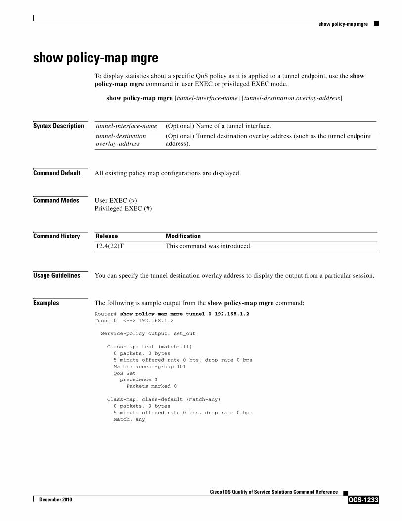
show policy-map mgre
QOS-1233Cisco IOS Quality of Service Solutions Command Reference
December 2010
show policy-map mgreTo display statistics about a specific QoS policy as it is applied to a tunnel endpoint, use the show policy-map mgre command in user EXEC or privileged EXEC mode.
show policy-map mgre [tunnel-interface-name] [tunnel-destination overlay-address]
Syntax Description
Command Default All existing policy map configurations are displayed.
Command Modes User EXEC (>)Privileged EXEC (#)
Command History
Usage Guidelines You can specify the tunnel destination overlay address to display the output from a particular session.
Examples The following is sample output from the show policy-map mgre command:
Router# show policy-map mgre tunnel 0 192.168.1.2Tunnel0 <--> 192.168.1.2
Service-policy output: set_out
Class-map: test (match-all) 0 packets, 0 bytes 5 minute offered rate 0 bps, drop rate 0 bps Match: access-group 101 QoS Set precedence 3 Packets marked 0
Class-map: class-default (match-any) 0 packets, 0 bytes 5 minute offered rate 0 bps, drop rate 0 bps Match: any
tunnel-interface-name (Optional) Name of a tunnel interface.
tunnel-destination overlay-address
(Optional) Tunnel destination overlay address (such as the tunnel endpoint address).
Release Modification
12.4(22)T This command was introduced.

show policy-map mgre
QOS-1234Cisco IOS Quality of Service Solutions Command Reference
December 2010
Table 215 describes the significant fields shown in the display.
Related Commands
Table 215 show policy-map mgre Field Descriptions
Field Description
Tunnel0 Name of the tunnel endpoint.
192.168.1.2 Tunnel destination overlay address.
Service-policy output
Name of the output service policy applied to the specified interface or VC.
Class-map Class of traffic being displayed. Output is displayed for each configured class in the policy. The choice for implementing class matches (for example, match-all or match-any) can also appear next to the traffic class.
packets and bytes Number of packets (also shown in bytes) identified as belonging to the class of traffic being displayed.
offered rate Rate, in kbps, of packets coming in to the class.
Note If the packets are compressed over an outgoing interface, the improved packet rate achieved by packet compression is not reflected in the offered rate. Also, if the packets are classified before they enter a combination of tunnels (for example, a generic routing encapsulation (GRE) tunnel and an IP Security (IPSec) tunnel), the offered rate does not include all the extra overhead associated with tunnel encapsulation in general. Depending on the configuration, the offered rate may include no overhead, may include the overhead for only one tunnel encapsulation, or may include the overhead for all tunnel encapsulations. In most of the GRE and IPSec tunnel configurations, the offered rate includes the overhead for GRE tunnel encapsulation only.
drop rate Rate, in kbps, at which packets are dropped from the class. The drop rate is calculated by subtracting the number of successfully transmitted packets from the offered rate.
Match Match criteria specified for the class of traffic. Choices include criteria such as IP precedence, IP differentiated services code point (DSCP) value, Multiprotocol Label Switching (MPLS) experimental (EXP) value, access groups, and QoS groups. For more information about the variety of match criteria that are available, see the “Classifying Network Traffic” module in the Cisco IOS Quality of Service Solutions Configuration Guide.
QoS Set, qos-group, Packets marked
Indicates that class-based packet marking based on the QoS group has been configured. Includes the qos-group number and the number of packets marked.
Command Description
ip nhrp group Configures a NHRP group on a spoke.
ip nhrp map Statically configures the IP-to-NBMA address mapping of IP destinations connected to an NBMA network.
ip nhrp map group Adds NHRP groups to QoS policy mappings on a hub.
show dmvpn Displays DMVPN-specific session information.

show policy-map mgre
QOS-1235Cisco IOS Quality of Service Solutions Command Reference
December 2010
show ip nhrp Displays NHRP mapping information.
show ip nhrp group Displays the details of NHRP group mappings on a hub and the list of tunnels using each of the NHRP groups defined in the mappings.
Command Description

show policy-map multipoint
QOS-1236Cisco IOS Quality of Service Solutions Command Reference
December 2010
show policy-map multipoint To display the statistics about a specific quality of service (QoS) for a multipoint tunnel interface, use the show policy-map multipoint command in privileged EXEC mode.
show policy-map multipoint [tunnel interface-number [tunnel-destination-address]] [input [class class-name]] [output [class class-name]]
Syntax Description
Command Modes Privileged EXEC (#)
Command History
Usage Guidelines Use the show policy-map multipoint command to display the quality of service (QoS) policy map for a multipoint tunnel interface.
Examples The following is sample output from the show policy-map multipoint command:
Router# show policy-map multipoint
Interface Tunnel1 <--> 10.1.1.1
Service-policy output: parent-policy-out
Class-map: class-default (match-any) 9839 packets, 869608 bytes 5 minute offered rate 0 bps, drop rate 0 bps Match: any Queueing queue limit 250 packets (queue depth/total drops/no-buffer drops) 0/0/0 (pkts output/bytes output) 5000/710000 shape (average) cir 1000000, bc 4000, be 4000 target shape rate 1000000
tunnel (Optional) Displays the tunnel interface.
interface-number (Optional) Module and port number.
tunnel-destination-address
(Optional) Tunnel destination overlay address (such as the tunnel endpoint address).
input (Optional) Indicates that the statistics for the attached input policy will be displayed.
output (Optional) Indicates that the statistics for the attached output policy will be displayed.
class class-name (Optional) Displays the QoS policy actions for the specified class.
Release Modification
12.4(22)T This command was introduced.

show policy-map multipoint
QOS-1237Cisco IOS Quality of Service Solutions Command Reference
December 2010
Service-policy : child-policy-out
queue stats for all priority classes: Queueing queue limit 300 packets (queue depth/total drops/no-buffer drops) 0/0/0 (pkts output/bytes output) 5000/710000
Interface Tunnel1 <--> 10.1.2.1
Service-policy output: parent-policy-out
Class-map: class-default (match-any) 4723 packets, 479736 bytes 5 minute offered rate 0 bps, drop rate 0 bps Match: any Queueing queue limit 250 packets (queue depth/total drops/no-buffer drops) 0/0/0 (pkts output/bytes output) 0/0 shape (average) cir 1000000, bc 4000, be 4000 target shape rate 1000000
Service-policy : child-policy-out
queue stats for all priority classes: queue limit 300 packets (queue depth/total drops/no-buffer drops) 0/0/0 (pkts output/bytes output) 0/0
Related Commands Command Description
show platform qos policy-map
Displays the type and number of policy maps that are configured on the router.
show policy-map Displays the configuration of all classes for a specified service policy map or all classes for all existing policy maps.
show policy-map interface
Displays the configuration of all classes configured for all service policies on the specified interface or displays the classes for the service policy for a specific PVC on the interface.

show policy-map session
QOS-1238Cisco IOS Quality of Service Solutions Command Reference
December 2010
show policy-map sessionTo display the quality of service (QoS) policy map in effect for the Subscriber Service Switch (SSS) session, use the show policy-map session command in user EXEC or privileged EXEC mode.
show policy-map session [uid uid-number] [input class class-name | output class class-name]
Syntax Description
Command Modes User EXEC (>)Privileged EXEC (#)
Command History
Usage Guidelines Use the show policy-map session command with the uid keyword to verify the QoS policy map of a unique session ID in the input and output streams in the SSS session.
Use the show policy-map session command with the optional class class-name keyword argument combination to display statistics for a particular class. If you use the show policy-map session command without the class class-name keyword argument combination, statistics for all the classes defined in the QoS policy map display.
Examples This section contains sample output from the show policy-map session command.
Note The output of the show policy-map session command varies according to the QoS feature configured in the policy map. For instance, if traffic shaping or traffic queueing is configured in the policy maps, the statistics for those features will be included and the output will vary accordingly from what is shown in this section. Additional self-explanatory fields may appear, but the output will be very similar.
uid (Optional) Defines a unique session ID.
uid-number (Optional) Unique session ID. Range is from 1 to 65535.
input (Optional) Displays the upstream traffic of the unique session.
output (Optional) Displays the downstream traffic of the unique session.
class (Optional) Identifies the class that is part of the QoS policy-map definition.
class-name (Optional) Class name that is part of the QoS policy-map definition.
Release Modification
12.3(8)T This command was introduced.
12.2(28)SB This command was integrated into Cisco IOS Release 12.2(28)SB. This command was also modified to include per-session traffic shaping and traffic queueing statistics, if applicable.
12.2(33)SRC This command was integrated into Cisco IOS Release 12.2(33)SRC, and support for the Cisco 7600 series router was added.
12.2(33)SB Support for the Cisco 7300 series router was added. This command was also modified to include traffic shaping overhead accounting for ATM statistics, if applicable.

show policy-map session
QOS-1239Cisco IOS Quality of Service Solutions Command Reference
December 2010
The following example from the show policy-map session command displays QoS policy-map statistics for traffic in the downstream direction for the QoS policy maps configured:
Router# show policy-map session uid 401 output
SSS session identifier 401 -
Service-policy output: downstream-policy
Class-map: customer1234 (match-any) 4464 packets, 249984 bytes 5 minute offered rate 17000 bps, drop rate 0 bps Match: ip dscp cs1 cs2 cs3 cs4 4464 packets, 249984 bytes 5 minute rate 17000 bps QoS Set dscp af11 Packets marked 4464
Class-map: customer56 (match-any) 2232 packets, 124992 bytes 5 minute offered rate 8000 bps, drop rate 0 bps Match: ip dscp cs5 cs6 2232 packets, 124992 bytes 5 minute rate 8000 bps police: cir 20000 bps, bc 10000 bytes pir 40000 bps, be 10000 bytes conformed 2232 packets, 124992 bytes; actions: set-dscp-transmit af21 exceeded 0 packets, 0 bytes; actions: set-dscp-transmit af22 violated 0 packets, 0 bytes; actions: set-dscp-transmit af23 conformed 8000 bps, exceed 0 bps, violate 0 bps Class-map: customer7 (match-any) 1116 packets, 62496 bytes 5 minute offered rate 4000 bps, drop rate 4000 bps Match: ip dscp cs7 1116 packets, 62496 bytes 5 minute rate 4000 bps drop
Class-map: class-default (match-any) 1236 packets, 68272 bytes 5 minute offered rate 4000 bps, drop rate 0 bps Match: any

show policy-map session
QOS-1240Cisco IOS Quality of Service Solutions Command Reference
December 2010
Table 216 describes the significant fields shown in the display.
Table 216 show policy-map session Field Descriptions — Traffic in the Downstream Direction
Field Description
SSS session identifier Unique session identifier.
Service-policy output Name of the output service policy applied to the specified interface or virtual circuit (VC).
Class-map Class of traffic being displayed. Output is displayed for each configured class in the policy. The choice for implementing class matches (for example, match-all or match-any) can also appear next to the traffic class.
packets and bytes Number of packets (also shown in bytes) identified as belonging to the class of traffic being displayed.
offered rate Rate, in bps, of packets coming in to the class.
Note If the packets are compressed over an outgoing interface, the improved packet rate achieved by packet compression is not reflected in the offered rate. Also, if the packets are classified before they enter a combination of tunnels (for example, a generic routing encapsulation [GRE] tunnel and an IP Security [IPsec] tunnel), the offered rate does not include all the extra overhead associated with tunnel encapsulation in general. Depending on the configuration, the offered rate may include no overhead, may include the overhead for only one tunnel encapsulation, or may include the overhead for all tunnel encapsulations. In most of the GRE and IPsec tunnel configurations, the offered rate includes the overhead for GRE tunnel encapsulation only.
drop rate Rate, in bps, at which packets are dropped from the class. The drop rate is calculated by subtracting the number of successfully transmitted packets from the offered rate.
Match Match criteria specified for the class of traffic. Choices include criteria such as IP precedence, IP differentiated services code point (DSCP) value, Multiprotocol Label Switching (MPLS) experimental (EXP) value, access groups, and QoS groups. For more information about the variety of availablematch criteria options, see the “Applying QoS Features Using the MQC” module of the Cisco IOS Quality of Service Solutions Configuration Guide.
QoS Set Indicates that packet marking is in place.
dscp Value used in packet marking.
Packets marked The number of packets marked.

show policy-map session
QOS-1241Cisco IOS Quality of Service Solutions Command Reference
December 2010
The following example from the show policy-map session command displays QoS policy-map statistics for traffic in the upstream direction for all the QoS policy maps configured:
Router# show policy-map session uid 401 input
SSS session identifier 401 -
Service-policy input: upstream-policy
Class-map: class-default (match-any) 1920 packets, 111264 bytes 5 minute offered rate 7000 bps, drop rate 5000 bps Match: any police: cir 8000 bps, bc 1500 bytes conformed 488 packets, 29452 bytes; actions: transmit exceeded 1432 packets, 81812 bytes; actions: drop conformed 7000 bps, exceed 5000 bps
police Indicates that the police command has been configured to enable traffic policing. Also, displays the specified committed information rate (CIR), conform burst (bc) size, peak information rate (PIR), and peak burst (be) size used for marking packets.
conformed Displays the action to be taken on packets that conform to a specified rate. Displays the number of packets and bytes on which the action was taken.
exceeded Displays the action to be taken on packets that exceed a specified rate. Displays the number of packets and bytes on which the action was taken.
violated Displays the action to be taken on packets that violate a specified rate. Displays the number of packets and bytes on which the action was taken.
Table 216 show policy-map session Field Descriptions (continued)— Traffic in the Downstream
Field Description
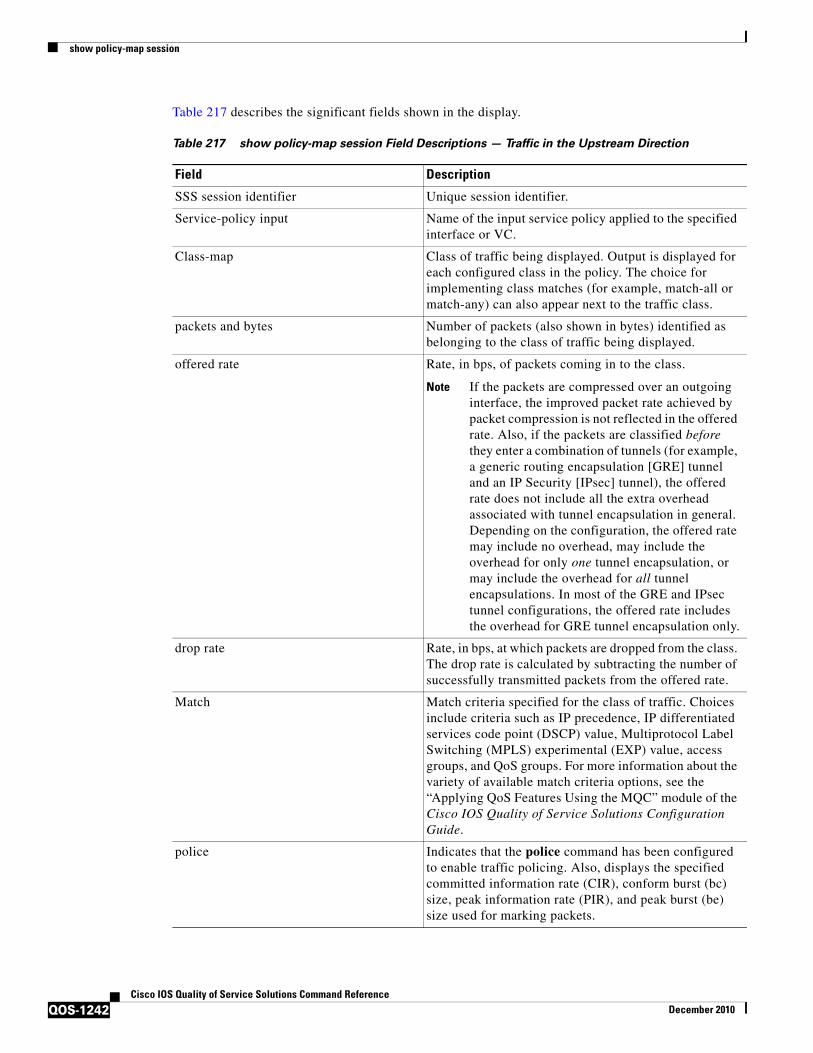
show policy-map session
QOS-1242Cisco IOS Quality of Service Solutions Command Reference
December 2010
Table 217 describes the significant fields shown in the display.
Table 217 show policy-map session Field Descriptions — Traffic in the Upstream Direction
Field Description
SSS session identifier Unique session identifier.
Service-policy input Name of the input service policy applied to the specified interface or VC.
Class-map Class of traffic being displayed. Output is displayed for each configured class in the policy. The choice for implementing class matches (for example, match-all or match-any) can also appear next to the traffic class.
packets and bytes Number of packets (also shown in bytes) identified as belonging to the class of traffic being displayed.
offered rate Rate, in bps, of packets coming in to the class.
Note If the packets are compressed over an outgoing interface, the improved packet rate achieved by packet compression is not reflected in the offered rate. Also, if the packets are classified before they enter a combination of tunnels (for example, a generic routing encapsulation [GRE] tunnel and an IP Security [IPsec] tunnel), the offered rate does not include all the extra overhead associated with tunnel encapsulation in general. Depending on the configuration, the offered rate may include no overhead, may include the overhead for only one tunnel encapsulation, or may include the overhead for all tunnel encapsulations. In most of the GRE and IPsec tunnel configurations, the offered rate includes the overhead for GRE tunnel encapsulation only.
drop rate Rate, in bps, at which packets are dropped from the class. The drop rate is calculated by subtracting the number of successfully transmitted packets from the offered rate.
Match Match criteria specified for the class of traffic. Choices include criteria such as IP precedence, IP differentiated services code point (DSCP) value, Multiprotocol Label Switching (MPLS) experimental (EXP) value, access groups, and QoS groups. For more information about the variety of available match criteria options, see the “Applying QoS Features Using the MQC” module of the Cisco IOS Quality of Service Solutions Configuration Guide.
police Indicates that the police command has been configured to enable traffic policing. Also, displays the specified committed information rate (CIR), conform burst (bc) size, peak information rate (PIR), and peak burst (be) size used for marking packets.

show policy-map session
QOS-1243Cisco IOS Quality of Service Solutions Command Reference
December 2010
Per-Session Shaping and Queueing Output: Example
The following is sample output of the show policy-map session command when per-session traffic shaping and traffic queueing are enabled. With per-session traffic shaping and queueing configured, traffic shaping and traffic queueing statistics are included in the output.
Note The QoS: Per-Session Shaping and Queueing on LNS feature does not support packet marking. That is, this feature does not support the use of the set command to mark packets. Therefore, statistics related to packet marking are not included in the output.
Router# show policy-map session uid 1 output
SSS session identifier 1 -
Service-policy output: parent
Class-map: class-default (match-any) 0 packets, 0 bytes 30 second offered rate 0 bps, drop rate 0 bps Match: any 0 packets, 0 bytes 30 second rate 0 bps Queueing queue limit 128 packets (queue depth/total drops/no-buffer drops) 0/0/0 (pkts output/bytes output) 0/0 shape (average) cir 512000, bc 12800, be 12800 target shape rate 512000
Service-policy : child
Class-map: prec0 (match-all) 0 packets, 0 bytes 30 second offered rate 0 bps, drop rate 0 bps Match: ip precedence 0 Queueing queue limit 38 packets (queue depth/total drops/no-buffer drops) 0/0/0 (pkts output/bytes output) 0/0 bandwidth 30% (153 kbps)
Class-map: prec2 (match-all) 0 packets, 0 bytes 30 second offered rate 0 bps, drop rate 0 bps
conformed Displays the action to be taken on packets that conform to a specified rate. Displays the number of packets and bytes on which the action was taken.
exceeded Displays the action to be taken on packets that exceed a specified rate. Displays the number of packets and bytes on which the action was taken.
violated Displays the action to be taken on packets that violate a specified rate. Displays the number of packets and bytes on which the action was taken.
Table 217 show policy-map session Field Descriptions (continued)— Traffic in the Upstream
Field Description

show policy-map session
QOS-1244Cisco IOS Quality of Service Solutions Command Reference
December 2010
Match: ip precedence 2 Queueing queue limit 44 packets (queue depth/total drops/no-buffer drops) 0/0/0 (pkts output/bytes output) 0/0 shape (average) cir 212000, bc 7632, be 7632 target shape rate 212000
Class-map: class-default (match-any) 0 packets, 0 bytes 30 second offered rate 0 bps, drop rate 0 bps Match: any 0 packets, 0 bytes 30 second rate 0 bps
queue limit 44 packets (queue depth/total drops/no-buffer drops) 0/0/0 (pkts output/bytes output) 0/0
Table 218 describes the significant fields related to per-session traffic shaping and queueing shown in the display.
.
Traffic Shaping Overhead Accounting for ATM: Example
The following output from the show policy-map session command indicates that ATM overhead accounting is enabled for shaping.
Router# show policy-map session uid 2 output
SSS session identifier 2 -
Service-policy output: ATM_OH_POLICY
Class-map: class-default (match-any) 0 packets, 0 bytes 30 second offered rate 0 bps, drop rate 0 bps Match: any Queueing queue limit 2500 packets (queue depth/total drops/no-buffer drops) 0/0/0 (pkts output/bytes output) 0/0 shape (average) cir 10000000, bc 40000, be 40000 target shape rate 10000000 Overhead Accounting Enabled
Table 218 show policy-map session Field Descriptions—Per-Session Traffic Shaping and Queueing
Configured
Field Description
Queueing Indicates that traffic queueing is enabled.
queue limit Displays the queue limit, in packets.
queue depth Current queue depth of the traffic shaper.
shape (average) cir, bc, be Indicates that average rate traffic shaping is enabled. Displays the committed information rate (CIR), the committed burst (bc) rate, and the excess burst (be) rate in bytes.
target shape rate Displays the traffic shaping rate, in bytes.
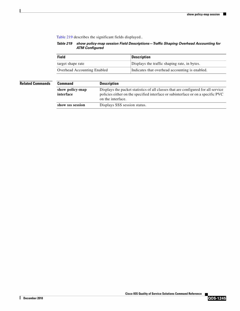
show policy-map session
QOS-1245Cisco IOS Quality of Service Solutions Command Reference
December 2010
Table 219 describes the significant fields displayed..
Related Commands
Table 219 show policy-map session Field Descriptions—Traffic Shaping Overhead Accounting for
ATM Configured
Field Description
target shape rate Displays the traffic shaping rate, in bytes.
Overhead Accounting Enabled Indicates that overhead accounting is enabled.
Command Description
show policy-map interface
Displays the packet statistics of all classes that are configured for all service policies either on the specified interface or subinterface or on a specific PVC on the interface.
show sss session Displays SSS session status.

show policy-map target service-group
QOS-1246Cisco IOS Quality of Service Solutions Command Reference
December 2010
show policy-map target service-groupTo display the policy-map information about service groups comprising Ethernet Virtual Circuits (EVCs), sub interfaces or sessions as members on the main interface or port channel, use the show policy-map target service-group command in privileged EXEC mode.
show policy-map target service-group [service-group-identifier]
Syntax Description
Defaults Policy-map information for all existing service groups is displayed.
Command Modes Privileged EXEC(#)
Command History
Usage Guidelines You should create the service groups and policy maps before using this command.
Examples This is a sample output of the show policy-map target service-group command.
Router# show policy-map target service-group 1000Port-channel1: Service Group 1000Service-policy output: policy1Counters last updated 02:04:11 agoClass-map: class-default (match-any) 0 packets, 0 bytes 30 second offered rate 0000 bps, drop rate 0000 bps Match: any Queueing queue limit 768 packets (queue depth/total drops/no-buffer drops) 0/0/0 (pkts output/bytes output) 0/0 shape (average) cir 20000000, bc 80000, be 80000 target shape rate 20000000
Table 220 describes the fields shown in the show policy-map target service-group command.
Table 220 Field Descriptions
service-group-identifier Service group identification number.
Release Modification
15.1(1)S This command is introduced.
Field Description
Port-channel: Service Group Specifies the interface type and service-group number.
Service-policy output Specifies the output service-policy name.
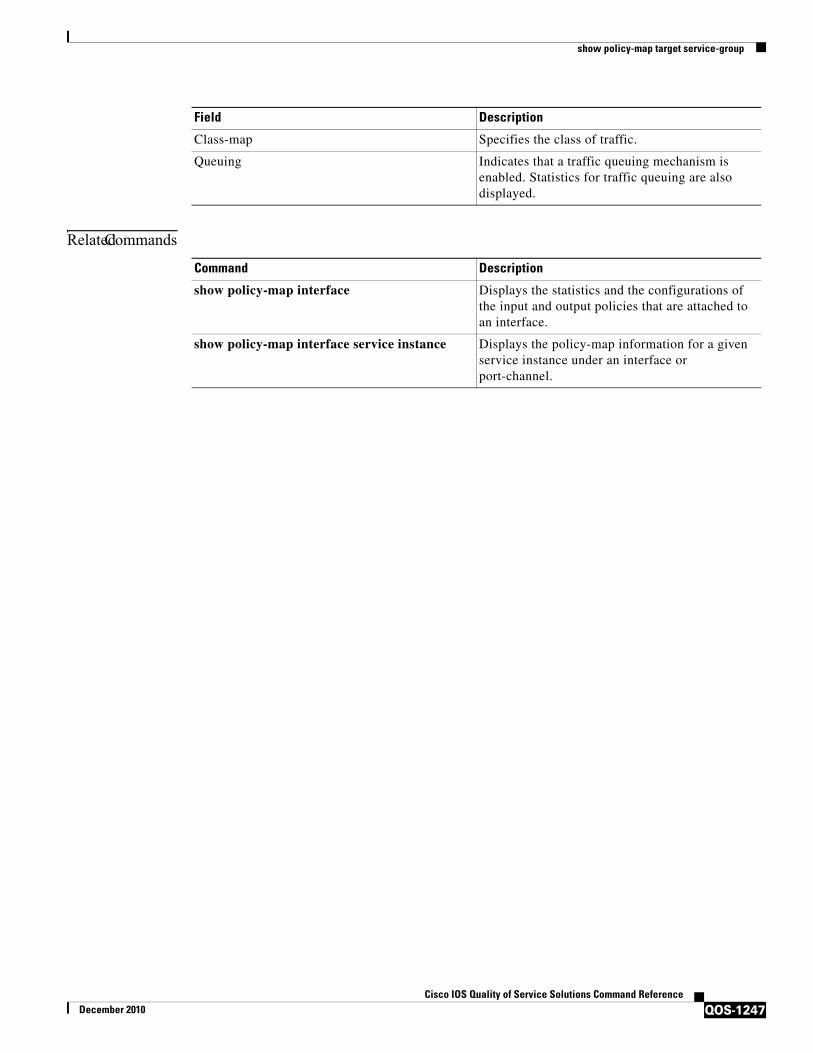
show policy-map target service-group
QOS-1247Cisco IOS Quality of Service Solutions Command Reference
December 2010
Related Commands
Class-map Specifies the class of traffic.
Queuing Indicates that a traffic queuing mechanism is enabled. Statistics for traffic queuing are also displayed.
Field Description
Command Description
show policy-map interface Displays the statistics and the configurations of the input and output policies that are attached to an interface.
show policy-map interface service instance Displays the policy-map information for a given service instance under an interface or port-channel.

show policy-map type access-control
QOS-1248Cisco IOS Quality of Service Solutions Command Reference
December 2010
show policy-map type access-control To display the access control for a specific policy map, use the show policy-map type access-control command in privileged EXEC mode.
show policy-map type access-control [policy-map-name [class class-map-name] | apn index-number | control-plane [all | subinterface] [input [class class-map-name] | output [class class-map-name]] | interface type number [vc vpi/vci | vp vpi [subinterface] | input [class class-map-name] | output [class class-map-name]] | session [uid id] [input [class class-map-name] | output [class class-map-name]]]
Cisco ASR 1000 Series
show policy-map type access-control [control-plane [all [brief {timestamp | vrfs timestamp} | class class-map-name | service-instance [target-identifier]] | interface [type number [service-instance [target-identifier]]] | session [uid [id]] [input [class class-map-name] | output class [class-map-name]]
Syntax Description policy-map name (Optional) Policy-map name.
class class-map-name (Optional) Displays the Quality of Service (QoS) policy actions for the specified class.
apn index-number (Optional) Displays information about the Access Point Name (APN)-related policy.
control-plane (Optional) Displays information about control plane policy.
all (Optional) Displays all control plane policies.
subinterface (Optional) Displays statistics and policy details for an individual class for one of the following subinterfaces: cef-exception, host, transit.
input (Optional) Indicates that the statistics for the attached input policy are displayed.
output (Optional) Indicates that the statistics for the attached output policy are displayed.
interface [type number]
(Optional) Displays information about the Cisco IOS QoS policy interface.
vc (Optional) Displays the service policy for a specified virtual channel (VC).
vpi/ (Optional) Virtual path identifier (VPI) for this permanent virtual circuit (PVC). The absence of the slash mark ("/") and a VPI value defaults the VPI value to 0. On the Cisco 7200 and 7500 series routers, this value ranges from 0 to 255. The vpi and vci arguments cannot both be set to 0; if one is 0, the other cannot be 0.
vci (Optional) Virtual channel identifier (VCI) for this PVC. This value ranges from 0 to 1 less than the maximum value set for this interface by the atm vc-per-vp command. Typically, lower values 0 to 31 are reserved for specific traffic (F4 Operation, Administration, and Maintenance (OAM), switched virtual circuit (SVC) signaling, Integrated Local Management Interface (ILMI), and so on) and should not be used.
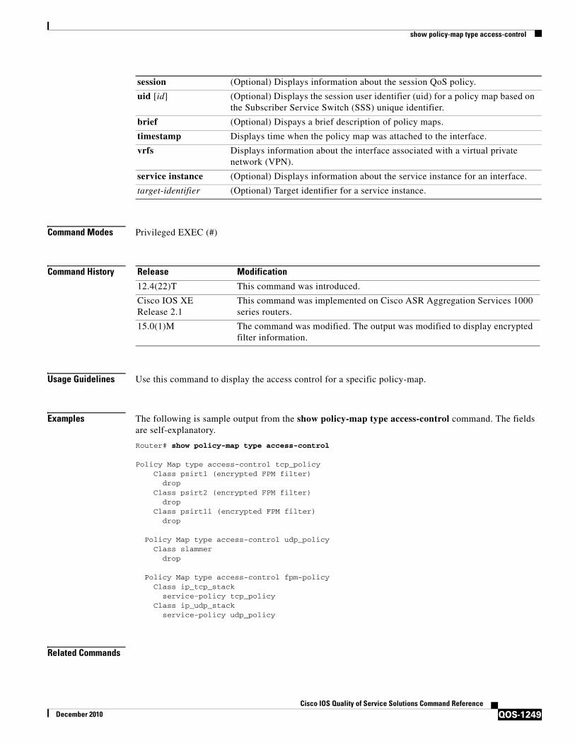
show policy-map type access-control
QOS-1249Cisco IOS Quality of Service Solutions Command Reference
December 2010
Command Modes Privileged EXEC (#)
Command History
Usage Guidelines Use this command to display the access control for a specific policy-map.
Examples The following is sample output from the show policy-map type access-control command. The fields are self-explanatory.
Router# show policy-map type access-control
Policy Map type access-control tcp_policy Class psirt1 (encrypted FPM filter) drop Class psirt2 (encrypted FPM filter) drop Class psirt11 (encrypted FPM filter) drop
Policy Map type access-control udp_policy Class slammer drop
Policy Map type access-control fpm-policy Class ip_tcp_stack service-policy tcp_policy Class ip_udp_stack service-policy udp_policy
Related Commands
session (Optional) Displays information about the session QoS policy.
uid [id] (Optional) Displays the session user identifier (uid) for a policy map based on the Subscriber Service Switch (SSS) unique identifier.
brief (Optional) Dispays a brief description of policy maps.
timestamp Displays time when the policy map was attached to the interface.
vrfs Displays information about the interface associated with a virtual private network (VPN).
service instance (Optional) Displays information about the service instance for an interface.
target-identifier (Optional) Target identifier for a service instance.
Release Modification
12.4(22)T This command was introduced.
Cisco IOS XE Release 2.1
This command was implemented on Cisco ASR Aggregation Services 1000 series routers.
15.0(1)M The command was modified. The output was modified to display encrypted filter information.
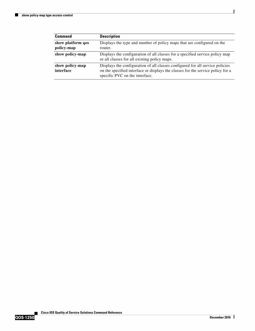
show policy-map type access-control
QOS-1250Cisco IOS Quality of Service Solutions Command Reference
December 2010
Command Description
show platform qos policy-map
Displays the type and number of policy maps that are configured on the router.
show policy-map Displays the configuration of all classes for a specified service policy map or all classes for all existing policy maps.
show policy-map interface
Displays the configuration of all classes configured for all service policies on the specified interface or displays the classes for the service policy for a specific PVC on the interface.

show policy-map type nat
QOS-1251Cisco IOS Quality of Service Solutions Command Reference
December 2010
show policy-map type natTo display the policy-map for Network Address Translation (NAT), use the show policy-map type NAT command in privileged EXEC mode.
show policy-map type nat [policymap-name [class classmap-name]] | apn index-number | | interface [type number[input [class classmap-name] | output[class classmap-name]] | session [uid [id]] input [class classmap-name] | output[class classmap-name]]
Syntax Description
Command Modes Privileged EXEC (#)
Command History
Examples The following is sample output from the show policy-map type NAT command:
Router# show policy-map type NAT
Policy Map ipnat-policyxx-in2outClass ipnat-defaultClass ipnat-class-acl-1Class ipnat-class-acl-2Class ipnat-class-acl-3 Policy Map ipnat-policyxx-out2inClass ipnat-default
policymap-name (Optional) Policy-map name.
class classmap-name (Optional) Displays the QoS policy actions for the specified class.
apn index-number (Optional) Displays Access Point Name (APN) related policy information.
interface [type number] (Optional) Displays Cisco IOS Quality of Service (QoS) Policy Interface information .
session (Optional) Displays session QoS Policy information.
uid [id] Displays session user identifier (uid) for a policy-map based on the Subscriber Service Switch (SSS) unique identifier.
input (Optional) Indicates that the statistics for the attached input policy is displayed.
output (Optional) Indicates that the statistics for the attached output policy is displayed.
Release Modification
12.4(11)T This command was introduced.

show policy-map type nat
QOS-1252Cisco IOS Quality of Service Solutions Command Reference
December 2010
Related Commands Command Description
show policy-map Displays the configuration of all classes for a specified service policy map or all classes for all existing policy maps.
show policy-map interface
Displays the configuration of all classes configured for all service policies on the specified interface or displays the classes for the service policy for a specific PVC on the interface.
show platform qos policy-map
Displays the type and number of policy maps that are configured on the router.

show policy-map type port-filter
QOS-1253Cisco IOS Quality of Service Solutions Command Reference
December 2010
show policy-map type port-filter To display information about policing of packets going to closed or nonlistened TCP/UDP ports, use the show policy-map type port-filter command in privileged EXEC mode.
show policy-map type port-filter[policy-map-name [class class-map-name] | apn apn-index | control-plane [all | subinterface] [input [class class-map-name] | output [class class-map-name]] | interface type number [vc vpi/vci | vp vpi [subinterface] | input [class class-map-name] | output [class class-map-name]] | session [uid id] [input [class class-map-name] | output [class class-map-name]]]
Syntax Description
Command Modes Privileged EXEC (#)
policy-map-name (Optional) Policy-map name.
class class-map-name (Optional) Displays the QoS policy actions for the specified class.
apn index-number (Optional) Displays Access Point Name (APN) related policy information.
control-plane (Optional) Displays information about control plane policy.
all (Optional) Displays all control plane policies.
subinterface (Optional) Displays statistics and policy details for an individual class for one of the following subinterfaces: cef-exception, host, transit.
interface [type number]
(Optional) Displays Cisco IOS QoS policy interface information.
vc (Optional) Displays the service policy for a specified virtual channel (VC).
vpi/ (Optional) virtual path identifier (VPI) for this PVC. The absence of the "/" and a vpi value defaults the vpi value to 0. On the Cisco 7200 and 7500 series routers, this value ranges from 0 to 255. The vpi and vci arguments cannot both be set to 0; if one is 0, the other cannot be 0.
vci (Optional) virtual channel identifier (VCI) for this PVC. This value ranges from 0 to 1 less than the maximum value set for this interface by the atm vc-per-vp command. Typically, lower values 0 to 31 are reserved for specific traffic (F4 Operation, Administration, and Maintenance (OAM), switched virtual circuit (SVC) signalling, Integrated Local Management Interface (ILMI), and so on) and should not be used.
vp Optional) Displays the service policy for a specified virtual path (VP).
session (Optional) Displays session QoS Policy information.
uid [id] Displays the session user identifier (uid) for a policy map based on the Subscriber Service Switch (SSS) unique identifier.
input (Optional) Indicates that the statistics for the attached input policy is displayed.
output (Optional) Indicates that the statistics for the attached output policy is displayed.

show policy-map type port-filter
QOS-1254Cisco IOS Quality of Service Solutions Command Reference
December 2010
Command History
Usage Guidelines Port filtering feature allows policing of packets going to closed or nonlistened TCP/UDP ports, while queue thresholding limits the number of packets for a specified protocol that is allowed in the control-plane IP input queue.
Examples The following example shows sample output for the show policy-map type port-filter command.
Router# show policy-map type port-filter
Policy Map type port-filter p1Policy Map type port-filter p4
Related Commands
Release Modification
12.4(22)T This command was introduced.
Command Description
show platform qos policy-map
Displays the type and number of policy maps that are configured on the router.
show policy-map Displays the configuration of all classes for a specified service policy map or all classes for all existing policy maps.
show policy-map interface
Displays the configuration of all classes configured for all service policies on the specified interface or displays the classes for the service policy for a specific PVC on the interface.
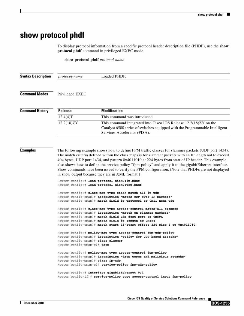
show protocol phdf
QOS-1255Cisco IOS Quality of Service Solutions Command Reference
December 2010
show protocol phdfTo display protocol information from a specific protocol header description file (PHDF), use the show protocol phdf command in privileged EXEC mode.
show protocol phdf protocol-name
Syntax Description
Command Modes Privileged EXEC
Command History
Examples The following example shows how to define FPM traffic classes for slammer packets (UDP port 1434). The match criteria defined within the class maps is for slammer packets with an IP length not to exceed 404 bytes, UDP port 1434, and pattern 0x4011010 at 224 bytes from start of IP header. This example also shows how to define the service policy “fpm-policy” and apply it to the gigabitEthernet interface. Show commands have been issued to verify the FPM configuration. (Note that PHDFs are not displayed in show output because they are in XML format.)
Router(config)# load protocol disk2:ip.phdfRouter(config)# load protocol disk2:udp.phdf
Router(config)# class-map type stack match-all ip-udpRouter(config-cmap)# description “match UDP over IP packets”Router(config-cmap)# match field ip protocol eq 0x11 next udp
Router(config)# class-map type access-control match-all slammerRouter(config-cmap)# description “match on slammer packets”Router(config-cmap)# match field udp dest-port eq 0x59ARouter(config-cmap)# match field ip length eq 0x194Router(config-cmap)# match start 13-start offset 224 size 4 eq 0x4011010
Router(config)# policy-map type access-control fpm-udp-policyRouter(config-pmap)# description “policy for UDP based attacks”Router(config-pmap)# class slammerRouter(config-pmap-c)# drop
Router(config)# policy-map type access-control fpm-policyRouter(config-pmap)# description “drop worms and malicious attacks”Router(config-pmap)# class ip-udpRouter(config-pmap-c)# service-policy fpm-udp-policy
Router(config)# interface gigabitEthernet 0/1Router(config-if)# service-policy type access-control input fpm-policy
protocol-name Loaded PHDF.
Release Modification
12.4(4)T This command was introduced.
12.2(18)ZY This command integrated into Cisco IOS Release 12.2(18)ZY on the Catalyst 6500 series of switches equipped with the Programmable Intelligent Services Accelerator (PISA).

show protocol phdf
QOS-1256Cisco IOS Quality of Service Solutions Command Reference
December 2010
Router# show protocols phdf ip
Protocol ID: 1Protocol name: IPDescription: Definition-for-the-IP-protocolOriginal file name: disk2:ip.phdfHeader length: 20Constraint(s):Total number of fields: 12Field id: 0, version, IP-versionFixed offset. offset 0Constant length. Length: 4Field id: 1, ihl, IP-Header-LengthFixed offset. offset 4Constant length. Length: 4Field id: 2, tos, IP-Type-of-ServiceFixed offset. offset 8Constant length. Length: 8Field id: 3, length, IP-Total-LengthFixed offset. offset 16Constant length. Length: 16Field id: 4, identification, IP-IdentificationFixed offset. offset 32Constant length. Length: 16Field id: 5, flags, IP-Fragmentation-FlagsFixed offset. offset 48Constant length. Length: 3Field id: 6, fragment-offset, IP-Fragmentation-OffsetFixed offset. offset 51Constant length. Length: 13Field id: 7, ttl, Definition-for-the-IP-TTLFixed offset. offset 64Constant length. Length: 8Field id: 8, protocol, IP-ProtocolFixed offset. offset 72Constant length. Length: 8Field id: 9, checksum, IP-Header-ChecksumFixed offset. offset 80Constant length. Length: 16Field id: 10, source-addr, IP-Source-AddressFixed offset. offset 96Constant length. Length: 32Field id: 11, dest-addr, IP-Destination-AddressFixed offset. offset 128Constant length. Length: 32
Router# show protocols phdf udp
Protocol ID: 3Protocol name: UDPDescription: UDP-ProtocolOriginal file name: disk2:udp.phdfHeader length: 8Constraint(s):Total number of fields: 4Field id: 0, source-port, UDP-Source-PortFixed offset. offset 0Constant length. Length: 16Field id: 1, dest-port, UDP-Destination-PortFixed offset. offset 16Constant length. Length: 16Field id: 2, length, UDP-LengthFixed offset. offset 32Constant length. Length: 16

show protocol phdf
QOS-1257Cisco IOS Quality of Service Solutions Command Reference
December 2010
Field id: 3, checksum, UDP-ChecksumFixed offset. offset 48Constant length. Length: 16
Related Commands Command Description
load protocol Loads a PHDF onto a router.

show qbm client
QOS-1258Cisco IOS Quality of Service Solutions Command Reference
December 2010
show qbm clientTo display quality of service (QoS) bandwidth manager (QBM) clients (applications) and their IDs, use the show qbm client command in user EXEC or privileged EXEC mode.
show qbm client
Syntax Description This command has no arguments or keywords.
Command Modes User EXEC (>)Privileged EXEC (#)
Command History
Usage Guidelines Use the show qbm client command to confirm that a subset of Cisco IOS software has registered with QBM.
A subset of Cisco IOS software becomes a client of QBM by calling a QBM registration application programming interface (API) and receiving an ID. If the subset has not registered, then it is not a client.
Examples The following is sample output from the show qbm client command when RSVP aggregation is enabled:
Router# show qbm client
Client Name Client ID RSVP BW Admit 1 RSVP rfc3175 AggResv 2
Table 221 describes the significant fields shown in the display.
Release Modification
12.2(33)SRC This command was introduced.
Cisco IOS XE Releas 2.6
This command was integrated into Cisco IOS XE Release 2.6.
Table 221 show qbm client command Field Descriptions
Field Description
Client Name The name of the application.
• RSVP BW Admit—The RSVP QBM client used for admitting bandwidth into QBM bandwidth pools.
• RSVP rfc3175 AggResv—RSVP aggregation as defined in RFC 3175, Aggregation of RSVP for IPv4 and IPv6 Reservations.
– This client is used to create and maintain QBM bandwidth pools for RSVP aggregate reservations.
Client ID The identifier of the application. One client ID exists per client.

show qbm client
QOS-1259Cisco IOS Quality of Service Solutions Command Reference
December 2010
Related Commands Command Description
debug qbm Enables debugging output for QBM options.
show qbm pool Displays allocated QBM pools and associated objects.

show qbm pool
QOS-1260Cisco IOS Quality of Service Solutions Command Reference
December 2010
show qbm poolTo display allocated quality of service (QoS) bandwidth manager (QBM) pools and identify the objects with which they are associated, use the show qbm pool command in user EXEC or privileged EXEC mode.
show qbm pool [id pool-id]
Syntax Description
Command Default If you enter the show qbm pool command without the optional keyword/argument combination, the command displays information for all configured QBM pools.
Command Modes User EXEC (>)Privileged EXEC (#)
Command History
Usage Guidelines Use the show qbm pool command to display information for all configured QBM pools or for a specified pool. If you enter a pool ID that does not exist, you receive an error message.
This command is useful for troubleshooting QBM operation.
Examples The following sample output is from the show qbm pool command when RSVP aggregation is enabled:
Router# show qbm pool
Total number of pools allocated: 1
Pool ID 0x00000009Associated object: 'RSVP 3175 AggResv 192.168.40.1->192.168.50.1_ef(46)' Minimum: 300Kbps Oper Status: OPERATIONAL Oper Minimum: 300KbpsUsed Bandwidth: 80Kbps
Table 221 describes the significant fields shown in the display.
id pool-id (Optional) Displays the identifier for a specified bandwidth pool that is performing admission control. The values must be between 0x0 and 0xffffffff; there is no default.
Release Modification
12.2(33)SRC This command was introduced.
Cisco IOS XE Release 2.6
This command was integrated into Cisco IOS XE Release 2.6.
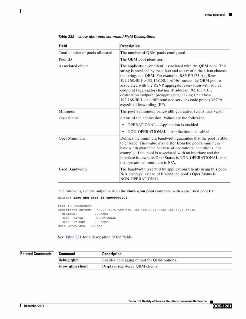
show qbm pool
QOS-1261Cisco IOS Quality of Service Solutions Command Reference
December 2010
The following sample output is from the show qbm pool command with a specified pool ID:
Router# show qbm pool id 0x000000006
Pool ID 0x00000009Associated object: 'RSVP 3175 AggResv 192.168.40.1->192.168.50.1_ef(46)' Minimum: 300Kbps Oper Status: OPERATIONAL Oper Minimum: 300KbpsUsed Bandwidth: 80Kbps
See Table 221 for a description of the fields.
Related Commands
Table 222 show qbm pool command Field Descriptions
Field Description
Total number of pools allocated The number of QBM pools configured.
Pool ID The QBM pool identifier.
Associated object The application (or client) associated with the QBM pool. This string is provided by the client and as a result, the client chooses the string, not QBM. For example, RSVP 3175 AggResv 192.168.40.1->192.168.50.1_ef(46) means the QBM pool is associated with the RSVP aggregate reservation with source endpoint (aggregator) having IP address 192.168.40.1, destination endpoint (deaggregator) having IP address 192.168.50.1, and differentiated services code point (DSCP) expedited forwarding (EF).
Minimum The pool’s minimum bandwidth guarantee. (Units may vary.)
Oper Status Status of the application. Values are the following:
• OPERATIONAL—Application is enabled.
• NON-OPERATIONAL—Application is disabled.
Oper Minimum Defines the minimum bandwidth guarantee that the pool is able to enforce. This value may differ from the pool’s minimum bandwidth guarantee because of operational conditions. For example, if the pool is associated with an interface and the interface is down, its Oper Status is NON-OPERATIONAL, then the operational minimum is N/A.
Used Bandwidth The bandwidth reserved by applications/clients using this pool. N/A displays instead of 0 when the pool’s Oper Status is NON-OPERATIONAL.
Command Description
debug qbm Enables debugging output for QBM options.
show qbm client Displays registered QBM clients.

show qdm status
QOS-1262Cisco IOS Quality of Service Solutions Command Reference
December 2010
show qdm statusTo display the status of the active Quality of Service Device Manager (QDM) clients that are connected to the router, use the show qdm status command in EXEC mode.
show qdm status
Syntax Description This command has no arguments or keywords.
Command Modes EXEC
Command History
Usage Guidelines The show qdm status command can be used on the Cisco 7600 series router.
The output of the show qdm status command includes the following information:
• Number of connected clients
• Client IDs
• Version of the client software
• IP addresses of the connected clients
• Duration of the connection
Note QDM is not supported on Optical Service Module (OSM) interfaces.
Examples The following example illustrates the show qdm status output when two QDM clients are connected to the router:
Router# show qdm status
Number of QDM Clients :2QDM Client v1.0(0.13)-System_1 @ 172.16.0.0 (id:30) connected since 09:22:36 UTC Wed Mar 15 2000QDM Client v1.0(0.12)-System_2 @ 172.31.255.255 (id:29) connected since 17:10:23 UTC Tue Mar 14 2000
Release Modification
12.1(1)E This command was introduced.
12.1(5)T This command was integrated into Cisco IOS Release 12.1(5)T.
12.2(14)SX Support for this command was introduced on the Supervisor Engine 720.
12.2(17d)SXB This command was implemented on the Supervisor Engine 2 and integrated into Cisco IOS Release 12.2(17d)SXB.
12.2(33)SRA This command was integrated into Cisco IOS Release 12.2(33)SRA.

show qdm status
QOS-1263Cisco IOS Quality of Service Solutions Command Reference
December 2010
Related Commands Command Description
disconnect qdm Disconnects a QDM client.

show queue
QOS-1264Cisco IOS Quality of Service Solutions Command Reference
December 2010
show queue
Note Effective with Cisco IOS XE Release 2.6, Cisco IOS Release 15.0(1)S, and Cisco IOS Release 15.1(3)T, the show queue command is hidden. Although this command is still available in Cisco IOS software, the CLI interactive Help does not display it if you attempt to view it by entering a question mark at the command line.
This command will be completely removed in a future release, which means that you will need to use the appropriate replacement command (or sequence of commands). For more information (including a list of replacement commands), see the Legacy QoS Command Deprecation feature document in the Cisco IOS XE Quality of Service Solutions Configuration Guide or the Legacy QoS Command Deprecation feature document in the Cisco IOS Quality of Service Solutions Configuration Guide.
Note Effective with Cisco IOS XE Release 3.2S, the show queue command is replaced by a modular QoS CLI (MQC) command (or sequence of MQC commands). For the appropriate replacement command (or sequence of commands), see the Legacy QoS Command Deprecation feature document in the Cisco IOS XE Quality of Service Solutions Configuration Guide.
To display the contents of packets inside a queue for a particular interface or virtual circuit (VC), use the show queue command in user EXEC or privileged EXEC mode.
show queue interface-name interface-number [queue-number] [vc [vpi/] vci]
Syntax Description interface-name The name of the interface.
interface-number The number of the interface.
queue-number (Optional) The number of the queue. The queue number is a number from 1 to 16.
vc (Optional) For ATM interfaces only, shows the fair queueing configuration for a specified permanent virtual circuit (PVC). The name can be up to 16 characters long.

show queue
QOS-1265Cisco IOS Quality of Service Solutions Command Reference
December 2010
Command Modes User EXEC (>)Privileged EXEC (#)
Command History
Usage Guidelines This command displays the contents of packets inside a queue for a particular interface or VC.
This command does not support VIP-distributed Weighted Random Early Detection WRED (DWRED). You can use the vc keyword and the show queue command arguments to display output for a PVC only on Enhanced ATM port adapters (PA-A3) that support per-VC queueing.
vpi/ (Optional) ATM network virtual path identifier (VPI) for this PVC. The absence of the “/” and a vpi value defaults the vpi value to 0.
On the Cisco 7200 and Cisco 7500 series routers, this value ranges from 0 to 255.
The vpi and vci arguments cannot both be set to 0; if one is 0, the other cannot be 0.
If this value is omitted, information for all VCs on the specified ATM interface or subinterface is displayed.
vci (Optional) ATM network virtual channel identifier (VCI) for this PVC. This value ranges from 0 to 1 less than the maximum value set for this interface by the atm vc-per-vp command. Typically, lower values 0 to 31 are reserved for specific traffic (F4 Operation, Administration, and Maintenance (OAM), switched virtual circuit (SVC) signalling, Integrated Local Management Interface (ILMI), and so on) and should not be used.
The VCI is a 16-bit field in the header of the ATM cell. The VCI value is unique only on a single link, not throughout the ATM network, because it has local significance only.
The vpi and vci arguments cannot both be set to 0; if one is 0, the other cannot be 0.
Release Modification
10.2 This command was introduced.
12.2(33)SRA This command was integrated into Cisco IOS Release 12.2(33)SRA.
12.2SX This command is supported in the Cisco IOS Release 12.2SX train. Support in a specific 12.2SX release of this train depends on your feature set, platform, and platform hardware.
12.4(20)T This command was integrated into Cisco IOS Release 12.4(20)T, but without support for hierarchical queueing framework (HQF). See the “Usage Guidelines” for additional information.
Cisco IOS XE Release 2.6
This command was modified. This command was hidden.
15.0(1)S This command was modified. This command was hidden.
15.1(3)T This command was modified. This command was hidden.
Cisco IOS XE Release 3.2S
This command was replaced by an MQC command (or sequence of MQC commands).

show queue
QOS-1266Cisco IOS Quality of Service Solutions Command Reference
December 2010
This command does not support HQF. Use the show policy-map and the show policy-map interface commands to gather HQF information and statistics.
Examples The following examples show sample output when the show queue command is entered and either weighted fair queueing (WFQ), WRED, or flow-based WRED are configured.
WFQ Example
The following is sample output from the show queue command for PVC 33 on the atm2/0.33 ATM subinterface. Two conversations are active on this interface. WFQ ensures that both data streams receive equal bandwidth on the interface while they have messages in the pipeline.
Router# show queue atm2/0.33 vc 33
Interface ATM2/0.33 VC 0/33 Queueing strategy: weighted fair Total output drops per VC: 18149 Output queue: 57/512/64/18149 (size/max total/threshold/drops) Conversations 2/2/256 (active/max active/max total) Reserved Conversations 3/3 (allocated/max allocated)
(depth/weight/discards/tail drops/interleaves) 29/4096/7908/0/0 Conversation 264, linktype: ip, length: 254 source: 10.1.1.1, destination: 10.0.2.20, id: 0x0000, ttl: 59, TOS: 0 prot: 17, source port 1, destination port 1
(depth/weight/discards/tail drops/interleaves) 28/4096/10369/0/0 Conversation 265, linktype: ip, length: 254 source: 10.1.1.1, destination: 10.0.2.20, id: 0x0000, ttl: 59, TOS: 32 prot: 17, source port 1, destination port 2
Table 223 describes the significant fields shown in the display.
Table 223 show queue Field Descriptions for WFQ
Field Description
Queueing strategy Type of queueing active on this interface.
Total output drops per VC Total output packet drops.
Output queue Output queue size, in packets. Max total defines the aggregate queue size of all the WFQ flows. Threshold is the individual queue size of each conversation. Drops are the dropped packets from all the conversations in WFQ.
Conversations WFQ conversation number. A conversation becomes inactive or times out when its queue is empty. Each traffic flow in WFQ is based on a queue and represented by a conversation. Max active is the number of active conversations that have occurred since the queueing feature was configured. Max total is the number of conversations allowed simultaneously.
Reserved Conversations Traffic flows not captured by WFQ, such as class-based weighted fair queueing (CBWFQ) configured by the bandwidth command or a Resource Reservation Protocol (RSVP) flow, have a separate queue that is represented by a reserved conversation. Allocated is the current number of reserved conversations. Max allocated is the maximum number of allocated reserved conversations that have occurred.

show queue
QOS-1267Cisco IOS Quality of Service Solutions Command Reference
December 2010
Flow-Based WRED Example
The following is sample output from the show queue command issued for serial interface 1 on which flow-based WRED is configured. The output shows information for each packet in the queue; the data identifies the packet by number, the flow-based queue to which the packet belongs, the protocol used, and so forth.
Router# show queue Serial1
Output queue for Serial1 is 2/0 Packet 1, flow id:160, linktype:ip, length:118, flags:0x88 source:10.1.3.4, destination:10.1.2.2, id:0x0000, ttl:59, TOS:32 prot:17, source port 1, destination port 515 data:0x0001 0x0203 0x0405 0x0607 0x0809 0x0A0B 0x0C0D 0x0E0F 0x1011 0x1213 0x1415 0x1617 0x1819 0x1A1B Packet 2, flow id:161, linktype:ip, length:118, flags:0x88 source:10.1.3.5, destination:10.1.2.2, id:0x0000, ttl:59, TOS:64 prot:17, source port 1, destination port 515 data:0x0001 0x0203 0x0405 0x0607 0x0809 0x0A0B 0x0C0D 0x0E0F 0x1011 0x1213 0x1415 0x1617 0x1819 0x1A1B
Table 224 describes the significant fields shown in the display.
depth Queue depth for the conversation, in packets.
weight Weight used in WFQ.
discards Number of packets dropped from the conversation’s queue.
tail drops Number of packets dropped from the conversation when the queue is at capacity.
interleaves Number of packets interleaved.
linktype Protocol name.
length Packet length.
source Source IP address.
destination Destination IP address.
id Packet ID.
ttl Time to live count.
TOS IP type of service.
prot Layer 4 protocol number.
Table 223 show queue Field Descriptions for WFQ (continued)
Field Description
Table 224 show queue Field Descriptions for Flow-Based WRED
Field Description
Packet Packet number.
flow id Flow-based WRED number.
linktype Protocol name.
length Packet length.

show queue
QOS-1268Cisco IOS Quality of Service Solutions Command Reference
December 2010
WRED Example
The following is sample output from the show queue command issued for serial interface 3 on which WRED is configured. The output has been truncated to show only 2 of the 24 packets.
Router# show queue Serial3
Output queue for Serial3 is 24/0 Packet 1, linktype:ip, length:118, flags:0x88 source:10.1.3.25, destination:10.1.2.2, id:0x0000, ttl:59, TOS:192 prot:17, source port 1, destination port 515 data:0x0001 0x0203 0x0405 0x0607 0x0809 0x0A0B 0x0C0D 0x0E0F 0x1011 0x1213 0x1415 0x1617 0x1819 0x1A1B Packet 2, linktype:ip, length:118, flags:0x88 source:10.1.3.26, destination:10.1.2.2, id:0x0000, ttl:59, TOS:224 prot:17, source port 1, destination port 515 data:0x0001 0x0203 0x0405 0x0607 0x0809 0x0A0B 0x0C0D 0x0E0F 0x1011 0x1213 0x1415 0x1617 0x1819 0x1A1B
Related Commands
flags Internal version-specific flags.
source Source IP address.
destination Destination IP address.
id Packet ID.
ttl Time to live count.
prot Layer 4 protocol number.
data Packet data.
Table 224 show queue Field Descriptions for Flow-Based WRED (continued)
Field Description
Command Description
atm vc-per-vp Sets the maximum number of VCIs to support per VPI.
custom-queue-list Assigns a custom queue list to an interface.
fair-queue (class-default)
Specifies the number of dynamic queues to be reserved for use by the class-default class as part of the default class policy.
fair-queue (WFQ) Enables WFQ for an interface.
priority-group Assigns the specified priority list to an interface.
random-detect (interface)
Enables WRED or DWRED.
random-detect flow Enables flow-based WRED.
show frame-relay pvc Displays information and statistics about WFQ for a VIP-based interface.
show queueing Lists all or selected configured queueing strategies.
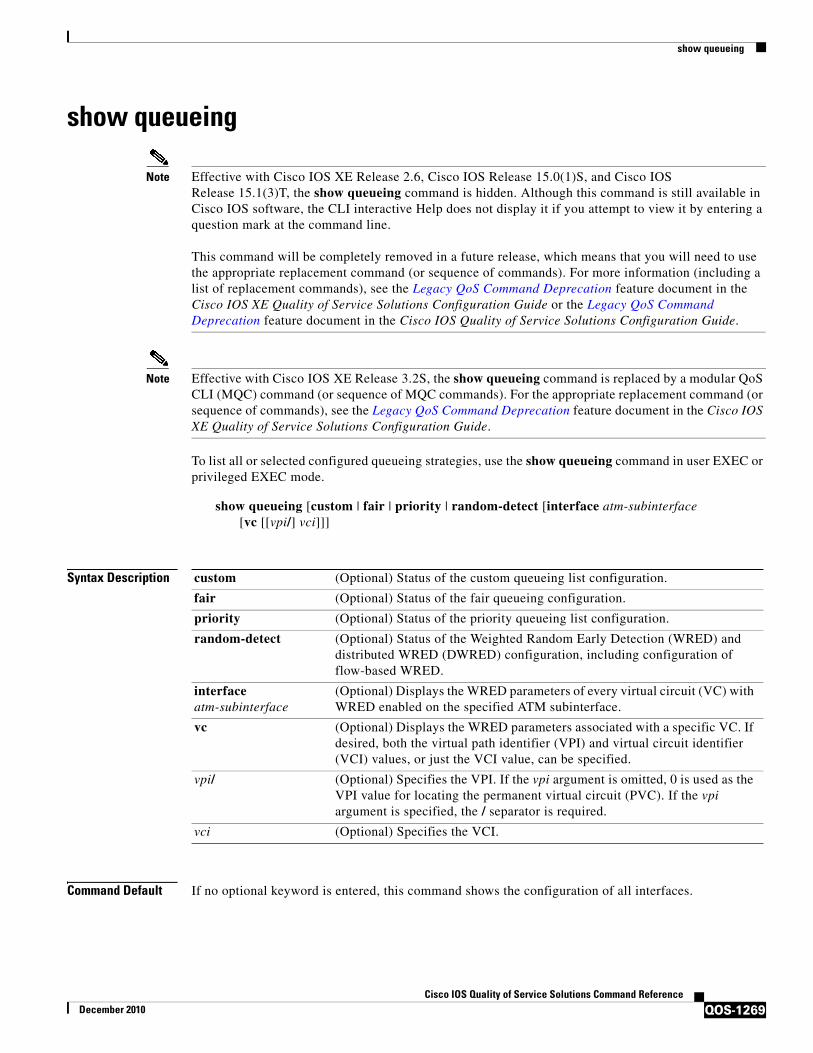
show queueing
QOS-1269Cisco IOS Quality of Service Solutions Command Reference
December 2010
show queueing
Note Effective with Cisco IOS XE Release 2.6, Cisco IOS Release 15.0(1)S, and Cisco IOS Release 15.1(3)T, the show queueing command is hidden. Although this command is still available in Cisco IOS software, the CLI interactive Help does not display it if you attempt to view it by entering a question mark at the command line.
This command will be completely removed in a future release, which means that you will need to use the appropriate replacement command (or sequence of commands). For more information (including a list of replacement commands), see the Legacy QoS Command Deprecation feature document in the Cisco IOS XE Quality of Service Solutions Configuration Guide or the Legacy QoS Command Deprecation feature document in the Cisco IOS Quality of Service Solutions Configuration Guide.
Note Effective with Cisco IOS XE Release 3.2S, the show queueing command is replaced by a modular QoS CLI (MQC) command (or sequence of MQC commands). For the appropriate replacement command (or sequence of commands), see the Legacy QoS Command Deprecation feature document in the Cisco IOS XE Quality of Service Solutions Configuration Guide.
To list all or selected configured queueing strategies, use the show queueing command in user EXEC or privileged EXEC mode.
show queueing [custom | fair | priority | random-detect [interface atm-subinterface [vc [[vpi/] vci]]]
Syntax Description
Command Default If no optional keyword is entered, this command shows the configuration of all interfaces.
custom (Optional) Status of the custom queueing list configuration.
fair (Optional) Status of the fair queueing configuration.
priority (Optional) Status of the priority queueing list configuration.
random-detect (Optional) Status of the Weighted Random Early Detection (WRED) and distributed WRED (DWRED) configuration, including configuration of flow-based WRED.
interface atm-subinterface
(Optional) Displays the WRED parameters of every virtual circuit (VC) with WRED enabled on the specified ATM subinterface.
vc (Optional) Displays the WRED parameters associated with a specific VC. If desired, both the virtual path identifier (VPI) and virtual circuit identifier (VCI) values, or just the VCI value, can be specified.
vpi/ (Optional) Specifies the VPI. If the vpi argument is omitted, 0 is used as the VPI value for locating the permanent virtual circuit (PVC). If the vpi argument is specified, the / separator is required.
vci (Optional) Specifies the VCI.

show queueing
QOS-1270Cisco IOS Quality of Service Solutions Command Reference
December 2010
Command Modes User EXEC (>)Privileged EXEC (#)
Command History
Usage Guidelines This command does not support HQF. Use the show policy-map and the show policy-map interface commands to gather HQF information and statistics.
Examples This section provides sample output from show queueing commands. Depending upon the interface or platform in use and the options enabled, the output that you see may vary slightly from the examples shown below.
• FR PIPQ: Example, page 1270
• Weighted Fair Queueing: Example, page 1271
• Custom Queueing: Example, page 1272
• Flow-Based WRED: Example, page 1272
• DWRED: Example, page 1272
FR PIPQ: Example
The following sample output shows that FR PIPQ (referred to as “DLCI priority queue”) is configured on serial interface 0. The output also shows the size of the four data-link connection identifier (DLCI) priority queues.
Router# show queueing
Current fair queue configuration:
Interface Discard Dynamic Reserved
Release Modification
10.3 This command was introduced.
12.0(4)T This command was integrated into Cisco IOS Release 12.0(4)T. The red keyword was changed to random-detect.
12.1(2)T This command was modified. This command was modified to include information about the Frame Relay PVC Interface Priority Queueing (FR PIPQ) feature.
12.2(2)T This command was integrated into Cisco IOS Release 12.2(2)T.
12.0(24)S This command was integrated into Cisco IOS Release 12.0(24)S.
12.2(14)S This command was integrated into Cisco IOS Release 12.2(14)S.
12.2(18)SXF2 This command was integrated into Cisco IOS Release 12.2(18)SXF2.
12.2(33)SRA This command was integrated into Cisco IOS Release 12.2(33)SRA.
Cisco IOS XE Release 2.6
This command was modified. This command was hidden.
15.0(1)S This command was modified. This command was hidden.
15.1(3)T This command was modified. This command was hidden.
Cisco IOS XE Release 3.2S
This command was replaced by an MQC command (or sequence of MQC commands).
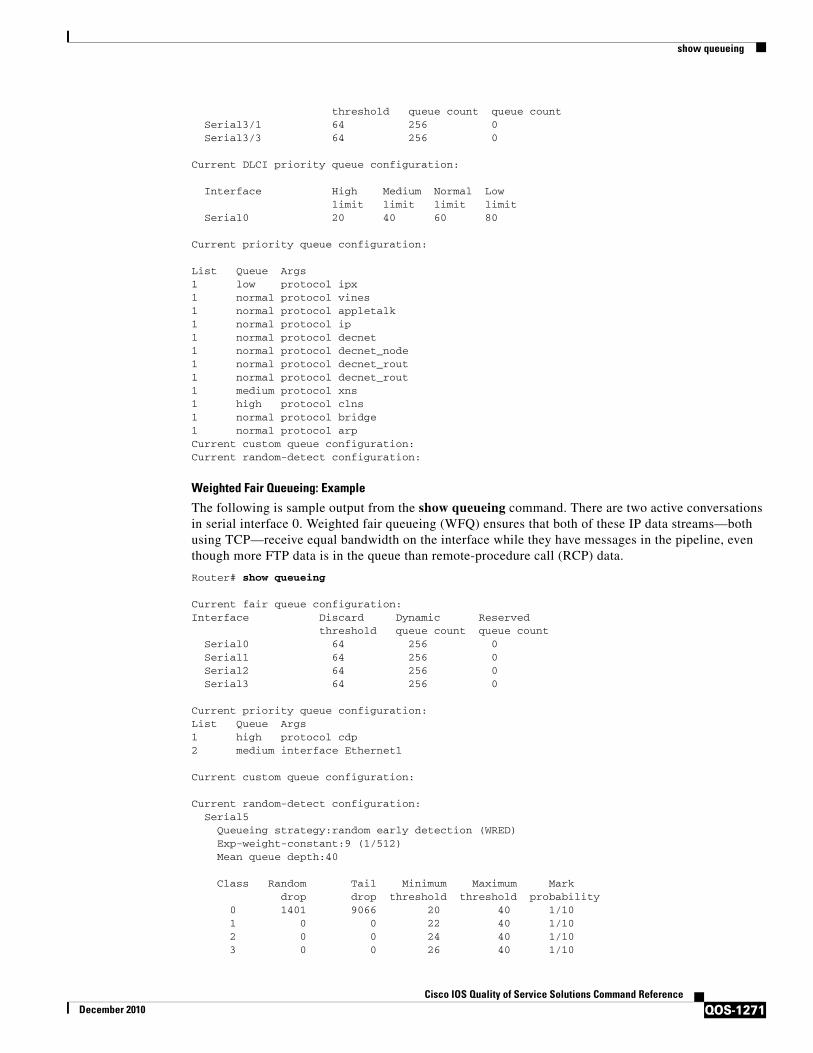
show queueing
QOS-1271Cisco IOS Quality of Service Solutions Command Reference
December 2010
threshold queue count queue count Serial3/1 64 256 0 Serial3/3 64 256 0
Current DLCI priority queue configuration:
Interface High Medium Normal Low limit limit limit limit Serial0 20 40 60 80
Current priority queue configuration:
List Queue Args 1 low protocol ipx1 normal protocol vines1 normal protocol appletalk1 normal protocol ip 1 normal protocol decnet1 normal protocol decnet_node1 normal protocol decnet_rout1 normal protocol decnet_rout1 medium protocol xns1 high protocol clns1 normal protocol bridge1 normal protocol arpCurrent custom queue configuration:Current random-detect configuration:
Weighted Fair Queueing: Example
The following is sample output from the show queueing command. There are two active conversations in serial interface 0. Weighted fair queueing (WFQ) ensures that both of these IP data streams—both using TCP—receive equal bandwidth on the interface while they have messages in the pipeline, even though more FTP data is in the queue than remote-procedure call (RCP) data.
Router# show queueing
Current fair queue configuration:Interface Discard Dynamic Reserved
threshold queue count queue countSerial0 64 256 0 Serial1 64 256 0 Serial2 64 256 0 Serial3 64 256 0
Current priority queue configuration:List Queue Args1 high protocol cdp 2 medium interface Ethernet1
Current custom queue configuration:
Current random-detect configuration: Serial5 Queueing strategy:random early detection (WRED)
Exp-weight-constant:9 (1/512) Mean queue depth:40
Class Random Tail Minimum Maximum Mark drop drop threshold threshold probability 0 1401 9066 20 40 1/10 1 0 0 22 40 1/10 2 0 0 24 40 1/10 3 0 0 26 40 1/10
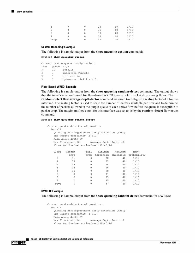
show queueing
QOS-1272Cisco IOS Quality of Service Solutions Command Reference
December 2010
4 0 0 28 40 1/10 5 0 0 31 40 1/10 6 0 0 33 40 1/10 7 0 0 35 40 1/10
rsvp 0 0 37 40 1/10
Custom Queueing: Example
The following is sample output from the show queueing custom command:
Router# show queueing custom
Current custom queue configuration:List Queue Args3 10 default3 3 interface Tunnel33 3 protocol ip3 3 byte-count 444 limit 3
Flow-Based WRED: Example
The following is sample output from the show queueing random-detect command. The output shows that the interface is configured for flow-based WRED to ensure fair packet drop among flows. The random-detect flow average-depth-factor command was used to configure a scaling factor of 8 for this interface. The scaling factor is used to scale the number of buffers available per flow and to determine the number of packets allowed in the output queue of each active flow before the queue is susceptible to packet drop. The maximum flow count for this interface was set to 16 by the random-detect flow count command.
Router# show queueing random-detect
Current random-detect configuration: Serial1 Queueing strategy:random early detection (WRED) Exp-weight-constant:9 (1/512) Mean queue depth:29 Max flow count:16 Average depth factor:8 Flows (active/max active/max):39/40/16 Class Random Tail Minimum Maximum Mark drop drop threshold threshold probability 0 31 0 20 40 1/10 1 33 0 22 40 1/10 2 18 0 24 40 1/10 3 14 0 26 40 1/10 4 10 0 28 40 1/10 5 0 0 31 40 1/10 6 0 0 33 40 1/10 7 0 0 35 40 1/10 rsvp 0 0 37 40 1/10
DWRED: Example
The following is sample output from the show queueing random-detect command for DWRED:
Current random-detect configuration: Serial1 Queueing strategy:random early detection (WRED) Exp-weight-constant:9 (1/512) Mean queue depth:29 Max flow count:16 Average depth factor:8 Flows (active/max active/max):39/40/16

show queueing
QOS-1273Cisco IOS Quality of Service Solutions Command Reference
December 2010
Class Random Tail Minimum Maximum Mark drop drop threshold threshold probability 0 31 0 20 40 1/10 1 33 0 22 40 1/10 2 18 0 24 40 1/10 3 14 0 26 40 1/10 4 10 0 28 40 1/10 5 0 0 31 40 1/10 6 0 0 33 40 1/10 7 0 0 35 40 1/10 rsvp 0 0 37 40 1/10
Current random-detect configuration: FastEthernet2/0/0 Queueing strategy:fifo Packet drop strategy:VIP-based random early detection (DWRED) Exp-weight-constant:9 (1/512) Mean queue depth:0 Queue size:0 Maximum available buffers:6308 Output packets:5 WRED drops:0 No buffer:0
Class Random Tail Minimum Maximum Mark Output drop drop threshold threshold probability Packets 0 0 0 109 218 1/10 5 1 0 0 122 218 1/10 0 2 0 0 135 218 1/10 0 3 0 0 148 218 1/10 0 4 0 0 161 218 1/10 0 5 0 0 174 218 1/10 0 6 0 0 187 218 1/10 0 7 0 0 200 218 1/10 0
Table 225 describes the significant fields shown in the display.
Table 225 show queueing Field Descriptions
Field Description
Discard threshold Number of messages allowed in each queue.
Dynamic queue count Number of dynamic queues used for best-effort conversations.
Reserved queue count Number of reservable queues used for reserved conversations.
High limit High DLCI priority queue size in maximum number of packets.
Medium limit Medium DLCI priority queue size, in maximum number of packets.
Normal limit Normal DLCI priority queue size, in maximum number of packets.
Low limit Low DLCI priority queue size, in maximum number of packets.
List Custom queueing—Number of the queue list.
Priority queueing—Number of the priority list.
Queue Custom queueing—Number of the queue.
Priority queueing—Priority queue level (high, medium, normal, or low keyword).
Args Packet matching criteria for that queue.
Exp-weight-constant Exponential weight factor.

show queueing
QOS-1274Cisco IOS Quality of Service Solutions Command Reference
December 2010
Related Commands
Mean queue depth Average queue depth. It is calculated based on the actual queue depth on the interface and the exponential weighting constant. It is a moving average. The minimum and maximum thresholds are compared against this value to determine drop decisions.
Class IP Precedence value.
Random drop Number of packets randomly dropped when the mean queue depth is between the minimum threshold value and the maximum threshold value for the specified IP Precedence value.
Tail drop Number of packets dropped when the mean queue depth is greater than the maximum threshold value for the specified IP Precedence value.
Minimum threshold Minimum WRED threshold, in number of packets.
Maximum threshold Maximum WRED threshold, in number of packets.
Mark probability Fraction of packets dropped when the average queue depth is at the maximum threshold.
Table 225 show queueing Field Descriptions (continued)
Field Description
Command Description
custom-queue-list Assigns a custom queue list to an interface.
exponential-weighting-constant Configures the exponential weight factor for the average queue size calculation for a WRED parameter group.
fair-queue (WFQ) Enables WFQ for an interface.
frame-relay interface-queue priority
Enables the FR PIPQ feature.
precedence (WRED group) Configures a WRED group for a particular IP Precedence.
priority-group Assigns the specified priority list to an interface.
priority-list interface Establishes queueing priorities on packets entering from a given interface.
priority-list queue-limit Specifies the maximum number of packets that can be waiting in each of the priority queues.
queue-list interface Establishes queueing priorities on packets entering on an interface.
queue-list queue byte-count Specifies how many bytes the system allows to be delivered from a given queue during a particular cycle.
random-detect (interface) Enables WRED or DWRED.
random-detect flow average-depth-factor
Sets the multiplier to be used in determining the average depth factor for a flow when flow-based WRED is enabled.
random-detect flow count Sets the flow count for flow-based WRED.
show interfaces Displays the statistical information specific to a serial interface.
show queue Displays the contents of packets inside a queue for a particular interface or VC.
show queueing interface Displays the queueing statistics of an interface or VC.

show queueing interface
QOS-1275Cisco IOS Quality of Service Solutions Command Reference
December 2010
show queueing interfaceTo display the queueing statistics of an interface, use the show queueing interface command in user EXEC or privileged EXEC mode.
show queueing interface type number [vc [[vpi/] vci]]
Catalyst 6500 Series Switches
show queueing interface {type number | null 0 | vlan vlan-id} [detailed]
Cisco 7600 Series Routers
show queueing interface {type number | null 0 | vlan vlan-id}
Syntax Description
Command Modes User EXEC (>)Privileged EXEC (#)
Cisco 7600 Series Routers
User EXEC (>)
Command History
type number Interface type and interface number.
For Cisco 7600 series routers, the valid interface types are ethernet, fastethernet, gigabitethernet, tengigabitethernet, pos, atm, and ge-wan.
For Cisco 7600 series routers, the interface number is the module and port number. See the “Usage Guidelines” section for more information.
vc (Optional) Shows the weighted fair queueing (WFQ) and Weighted Random Early Detection (WRED) parameters associated with a specific virtual circuit (VC). If desired, both the virtual path identifier (VPI) and virtual channel identifier (VCI) values, or just the VCI value, can be specified.
vpi/ (Optional) The VPI. If the vpi argument is omitted, 0 is used as the VPI value for locating the permanent virtual circuit (PVC). If the vpi argument is specified, the / separator is required.
vci (Optional) The VCI.
null 0 Specifies the null interface number; the only valid value is 0.
vlan vlan-id Specifies the VLAN identification number; valid values are from 1 to 4094.
detailed (Optional) Displays the detailed statistics information per policy class.
Release Modification
11.1(22)CC This command was introduced.
12.2(14)SX This command was implemented on the Supervisor Engine 720.
12.2(17d)SXB This command was implemented on the Supervisor Engine 2 and integrated into Cisco IOS Release 12.2(17d)SXB.
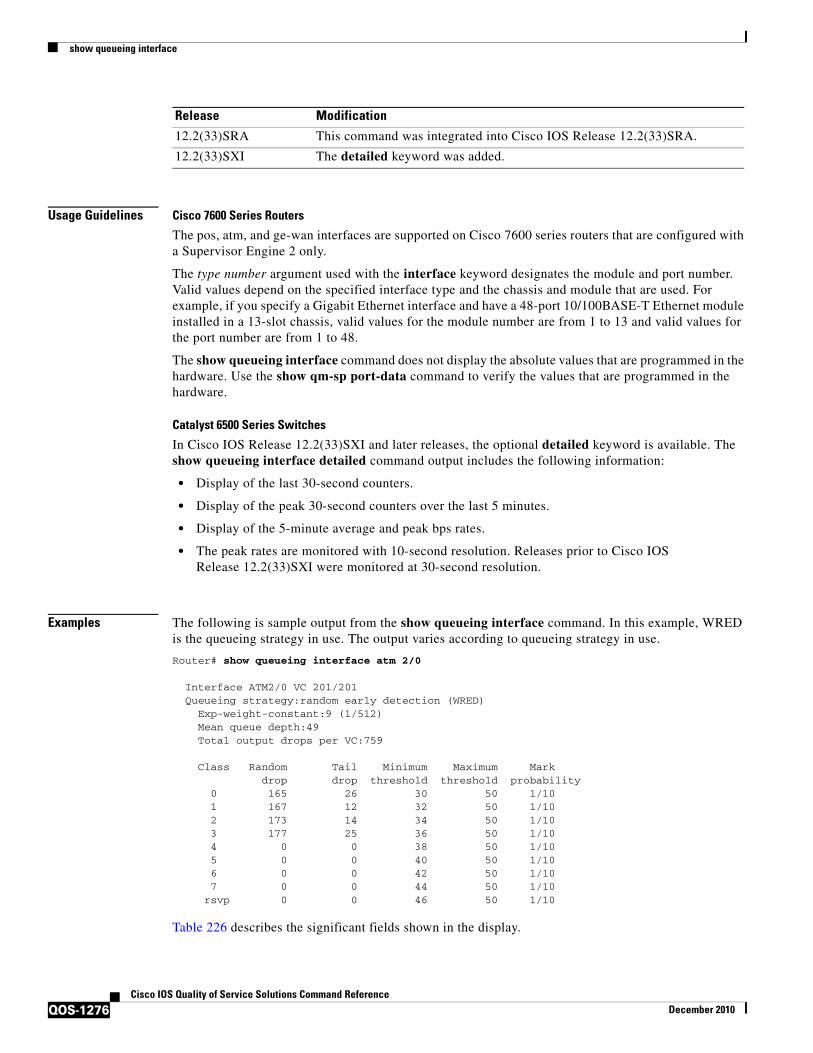
show queueing interface
QOS-1276Cisco IOS Quality of Service Solutions Command Reference
December 2010
Usage Guidelines Cisco 7600 Series Routers
The pos, atm, and ge-wan interfaces are supported on Cisco 7600 series routers that are configured with a Supervisor Engine 2 only.
The type number argument used with the interface keyword designates the module and port number. Valid values depend on the specified interface type and the chassis and module that are used. For example, if you specify a Gigabit Ethernet interface and have a 48-port 10/100BASE-T Ethernet module installed in a 13-slot chassis, valid values for the module number are from 1 to 13 and valid values for the port number are from 1 to 48.
The show queueing interface command does not display the absolute values that are programmed in the hardware. Use the show qm-sp port-data command to verify the values that are programmed in the hardware.
Catalyst 6500 Series Switches
In Cisco IOS Release 12.2(33)SXI and later releases, the optional detailed keyword is available. The show queueing interface detailed command output includes the following information:
• Display of the last 30-second counters.
• Display of the peak 30-second counters over the last 5 minutes.
• Display of the 5-minute average and peak bps rates.
• The peak rates are monitored with 10-second resolution. Releases prior to Cisco IOS Release 12.2(33)SXI were monitored at 30-second resolution.
Examples The following is sample output from the show queueing interface command. In this example, WRED is the queueing strategy in use. The output varies according to queueing strategy in use.
Router# show queueing interface atm 2/0
Interface ATM2/0 VC 201/201 Queueing strategy:random early detection (WRED) Exp-weight-constant:9 (1/512) Mean queue depth:49 Total output drops per VC:759
Class Random Tail Minimum Maximum Mark drop drop threshold threshold probability 0 165 26 30 50 1/10 1 167 12 32 50 1/10 2 173 14 34 50 1/10 3 177 25 36 50 1/10 4 0 0 38 50 1/10 5 0 0 40 50 1/10 6 0 0 42 50 1/10 7 0 0 44 50 1/10 rsvp 0 0 46 50 1/10
Table 226 describes the significant fields shown in the display.
12.2(33)SRA This command was integrated into Cisco IOS Release 12.2(33)SRA.
12.2(33)SXI The detailed keyword was added.
Release Modification

show queueing interface
QOS-1277Cisco IOS Quality of Service Solutions Command Reference
December 2010
The following is sample output from the show queueing interface command in Cisco IOS Release 12.2(33)SXI and later releases:
Router# show queueing interface gigabitethernet 3/27 detailed ... Packets dropped on Transmit: BPDU packets: 0
queue Total pkts 30-s pkts / peak 5 min average/peak pps [cos-map] ---------------------------------------------------------------------------- 1 443340 55523 / 66671 3334 / 44455 [0 1 ] 1 7778888 555555 / 666666 233333 / 340000 [2 3 ] 2 0 0 / 0 0 / 0 [4 5 ] 2 0 0 / 0 0 / 0 [6 7 ]...
Table 227 describes the significant fields added when you enter the detailed keyword.
Table 226 show queueing interface Field Descriptions
Field Description
Queueing strategy Name of the queueing strategy in use (for example, WRED).
Exp-weight-constant Exponential weight constant. Exponent used in the average queue size calculation for a WRED parameter group.
Mean queue depth Average queue depth based on the actual queue depth on the interface and the exponential weighting constant. It is a fluctuating average. The minimum and maximum thresholds are compared against this value to determine drop decisions.
Class IP precedence level.
Random drop Number of packets randomly dropped when the mean queue depth is between the minimum threshold value and the maximum threshold value for the specified IP precedence level.
Tail drop Number of packets dropped when the mean queue depth is greater than the maximum threshold value for the specified IP precedence level.
Minimum threshold Minimum WRED threshold in packets.
Maximum threshold Maximum WRED threshold in packets.
Mark probability Fraction of packets dropped when the average queue depth is at the maximum threshold.
Table 227 show queueing interface detailed Field Descriptions
Field Description
Packets dropped on Transmit Displays information regarding the packets dropped in transmission.
BPDU packets Number of Bridge Protocol Data Unit (BPDU) packets.
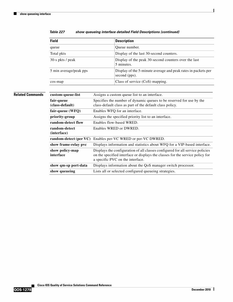
show queueing interface
QOS-1278Cisco IOS Quality of Service Solutions Command Reference
December 2010
Related Commands
queue Queue number.
Total pkts Display of the last 30-second counters.
30-s pkts / peak Display of the peak 30-second counters over the last 5 minutes.
5 min average/peak pps Display of the 5-minute average and peak rates in packets per second (pps).
cos-map Class of service (CoS) mapping.
Table 227 show queueing interface detailed Field Descriptions (continued)
Field Description
custom-queue-list Assigns a custom queue list to an interface.
fair-queue (class-default)
Specifies the number of dynamic queues to be reserved for use by the class-default class as part of the default class policy.
fair-queue (WFQ) Enables WFQ for an interface.
priority-group Assigns the specified priority list to an interface.
random-detect flow Enables flow-based WRED.
random-detect (interface)
Enables WRED or DWRED.
random-detect (per VC) Enables per-VC WRED or per-VC DWRED.
show frame-relay pvc Displays information and statistics about WFQ for a VIP-based interface.
show policy-map interface
Displays the configuration of all classes configured for all service policies on the specified interface or displays the classes for the service policy for a specific PVC on the interface.
show qm-sp port-data Displays information about the QoS manager switch processor.
show queueing Lists all or selected configured queueing strategies.

show random-detect-group
QOS-1279Cisco IOS Quality of Service Solutions Command Reference
December 2010
show random-detect-group
Note Effective with Cisco IOS Release 15.0(1)S and Cisco IOS Release 15.1(3)T, the show random-detect-group command is hidden. Although this command is still available in Cisco IOS software, the CLI interactive Help does not display it if you attempt to view it by entering a question mark at the command line.
This command will be completely removed in a future release, which means that you will need to use the appropriate replacement command (or sequence of commands). For more information (including a list of replacement commands), see the Legacy QoS Command Deprecation feature document in the Cisco IOS Quality of Service Solutions Configuration Guide.
To display the Weighted Random Early Detection (WRED) or distributed WRED (DWRED) parameter group, use the show random-detect-group command in privileged EXEC mode.
show random-detect-group [group-name]
Syntax Description
Command Default No WRED or DWRED parameter group is displayed.
Command Modes Privileged EXEC (#)
Command History
Usage Guidelines WRED is a congestion avoidance mechanism that slows traffic by randomly dropping packets when there is congestion. DWRED is similar to WRED but uses the Versatile Interface Processor (VIP) instead of the Route Switch Processor (RSP). WRED and DWRED are most useful when the traffic uses protocols such as TCP that respond to dropped packets by decreasing the transmission rate.
group-name (Optional) Name for the WRED or DWRED parameter group.
Release Modification
12.4(22)T This command was introduced in a release earlier than Cisco IOS Release 12.4(22)T.
12.2(33)SRC This command was integrated in a release earlier than Cisco IOS Release 12.2(33)SRC.
12.2(33)SXI This command was integrated into a release earlier than Cisco IOS Release 12.2(33)SXI.
15.0(1)S This command was modified. This command was hidden.
15.1(3)T This command was modified. This command was hidden.
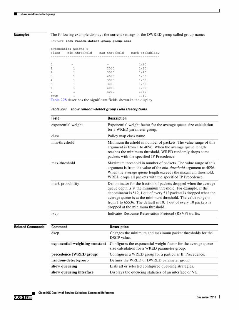
show random-detect-group
QOS-1280Cisco IOS Quality of Service Solutions Command Reference
December 2010
Examples The following example displays the current settings of the DWRED group called group-name:
Router# show random-detect-group group-name
exponential weight 9class min-threshold max-threshold mark-probablity----------------------------------------------------------
0 - - 1/101 1 2000 1/302 1 3000 1/403 1 4000 1/504 1 3000 1/605 1 3000 1/606 1 4000 1/607 1 4000 1/60rsvp 1 1 1/10
Table 228 describes the significant fields shown in the display.
Related Commands
Table 228 show random-detect group Field Descriptions
Field Description
exponential weight Exponential weight factor for the average queue size calculation for a WRED parameter group.
class Policy map class name.
min-threshold Minimum threshold in number of packets. The value range of this argument is from 1 to 4096. When the average queue length reaches the minimum threshold, WRED randomly drops some packets with the specified IP Precedence.
max-threshold Maximum threshold in number of packets. The value range of this argument is from the value of the min-threshold argument to 4096. When the average queue length exceeds the maximum threshold, WRED drops all packets with the specified IP Precedence.
mark-probability Denominator for the fraction of packets dropped when the average queue depth is at the minimum threshold. For example, if the denominator is 512, 1 out of every 512 packets is dropped when the average queue is at the minimum threshold. The value range is from 1 to 65536. The default is 10; 1 out of every 10 packets is dropped at the minimum threshold.
rsvp Indicates Resource Reservation Protocol (RSVP) traffic.
Command Description
dscp Changes the minimum and maximum packet thresholds for the DSCP value.
exponential-weighting-constant Configures the exponential weight factor for the average queue size calculation for a WRED parameter group.
precedence (WRED group) Configures a WRED group for a particular IP Precedence.
random-detect-group Defines the WRED or DWRED parameter group.
show queueing Lists all or selected configured queueing strategies.
show queueing interface Displays the queueing statistics of an interface or VC.
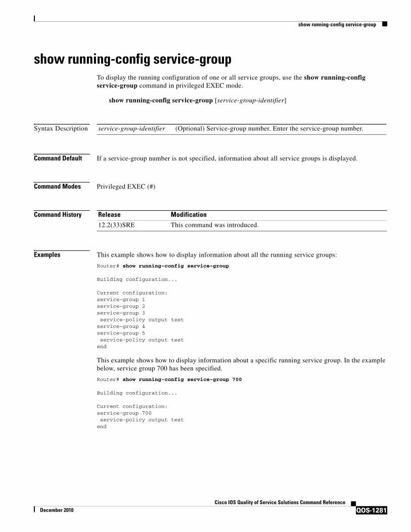
show running-config service-group
QOS-1281Cisco IOS Quality of Service Solutions Command Reference
December 2010
show running-config service-groupTo display the running configuration of one or all service groups, use the show running-config service-group command in privileged EXEC mode.
show running-config service-group [service-group-identifier]
Syntax Description
Command Default If a service-group number is not specified, information about all service groups is displayed.
Command Modes Privileged EXEC (#)
Command History
Examples This example shows how to display information about all the running service groups:
Router# show running-config service-group
Building configuration...
Current configuration:service-group 1service-group 2service-group 3 service-policy output testservice-group 4service-group 5 service-policy output testend
This example shows how to display information about a specific running service group. In the example below, service group 700 has been specified.
Router# show running-config service-group 700
Building configuration...
Current configuration:service-group 700 service-policy output testend
service-group-identifier (Optional) Service-group number. Enter the service-group number.
Release Modification
12.2(33)SRE This command was introduced.

show running-config service-group
QOS-1282Cisco IOS Quality of Service Solutions Command Reference
December 2010
Table 213 describes the significant fields shown in the display.
Table 229 show running-config service-group Field Descriptions
Field Description
service-group Indicates the service-group number.
service-policy output Indicates the output policy attached to the service group.
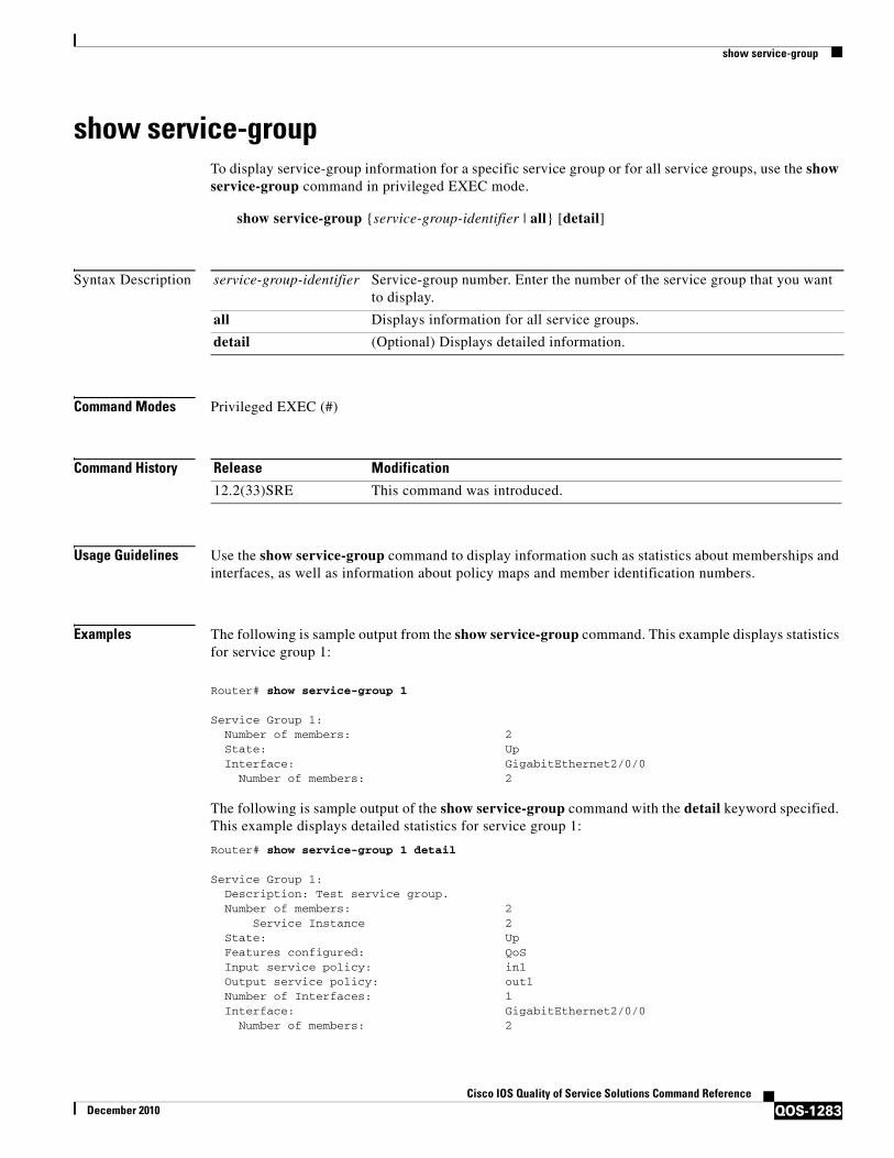
show service-group
QOS-1283Cisco IOS Quality of Service Solutions Command Reference
December 2010
show service-groupTo display service-group information for a specific service group or for all service groups, use the show service-group command in privileged EXEC mode.
show service-group {service-group-identifier | all} [detail]
Syntax Description
Command Modes Privileged EXEC (#)
Command History
Usage Guidelines Use the show service-group command to display information such as statistics about memberships and interfaces, as well as information about policy maps and member identification numbers.
Examples The following is sample output from the show service-group command. This example displays statistics for service group 1:
Router# show service-group 1
Service Group 1:Number of members: 2State: UpInterface: GigabitEthernet2/0/0
Number of members: 2
The following is sample output of the show service-group command with the detail keyword specified. This example displays detailed statistics for service group 1:
Router# show service-group 1 detail
Service Group 1:Description: Test service group. Number of members: 2
Service Instance 2State: UpFeatures configured: QoSInput service policy: in1Output service policy: out1Number of Interfaces: 1Interface: GigabitEthernet2/0/0
Number of members: 2
service-group-identifier Service-group number. Enter the number of the service group that you want to display.
all Displays information for all service groups.
detail (Optional) Displays detailed information.
Release Modification
12.2(33)SRE This command was introduced.
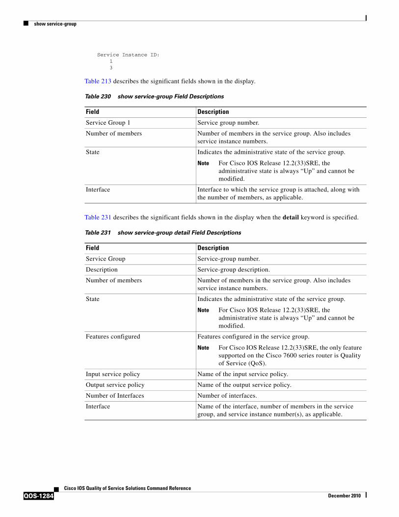
show service-group
QOS-1284Cisco IOS Quality of Service Solutions Command Reference
December 2010
Service Instance ID:13
Table 213 describes the significant fields shown in the display.
Table 231 describes the significant fields shown in the display when the detail keyword is specified.
Table 230 show service-group Field Descriptions
Field Description
Service Group 1 Service group number.
Number of members Number of members in the service group. Also includes service instance numbers.
State Indicates the administrative state of the service group.
Note For Cisco IOS Release 12.2(33)SRE, the administrative state is always “Up” and cannot be modified.
Interface Interface to which the service group is attached, along with the number of members, as applicable.
Table 231 show service-group detail Field Descriptions
Field Description
Service Group Service-group number.
Description Service-group description.
Number of members Number of members in the service group. Also includes service instance numbers.
State Indicates the administrative state of the service group.
Note For Cisco IOS Release 12.2(33)SRE, the administrative state is always “Up” and cannot be modified.
Features configured Features configured in the service group.
Note For Cisco IOS Release 12.2(33)SRE, the only feature supported on the Cisco 7600 series router is Quality of Service (QoS).
Input service policy Name of the input service policy.
Output service policy Name of the output service policy.
Number of Interfaces Number of interfaces.
Interface Name of the interface, number of members in the service group, and service instance number(s), as applicable.

show service-group interface
QOS-1285Cisco IOS Quality of Service Solutions Command Reference
December 2010
show service-group interfaceTo display service-group membership information by interface, use the show service-group interface command in privileged EXEC mode.
show service-group interface type number [group service-group-identifier] [detail]
Syntax Description
Command Default If an interface is not specified, service-group information about all interfaces is displayed.
Command Modes Privileged EXEC (#)
Command History
Examples This example shows how to display service-group membership information for Gigabit Ethernet interface 3/1:
Router# show service-group interface gigabitethernet 3/1
Interface GigabitEthernet3/1: Number of groups: 3 Group 1 2 3
This example shows how to display service-group detailed membership information for Gigabit Ethernet interface 3/1:
Router# show service-group interface gigabitethernet 3/1 detail
Interface GigabitEthernet3/1: Number of groups: 3Service Group 1: Number of members: 3000 Service Instance ID: 1 2
type Interface type. For more information, use the question mark (?) online help function.
number Interface number. For more information about the numbering syntax for your networking device, use the question mark (?) online help function.
group (Optional) Displays service-group information.
service-group-identifier (Optional) Service-group number. Enter the number of the service group that you want to display.
detail (Optional) Displays detailed statistics for all groups.
Release Modification
12.2(33)SRE This command was introduced.

show service-group interface
QOS-1286Cisco IOS Quality of Service Solutions Command Reference
December 2010
3 4 5 6 7 8 9 10
. . .
This example shows how to display detailed membership information for Gigabit Ethernet interface 3/1 service group 10:
Router# show service-group interface gigabitethernet 3/1 group 10 detail
Service Group 10:Number of members: 3Service Instance ID:100101102
Table 213 describes the significant fields shown in the display.
Table 232 show service-group interface service group Field Descriptions
Field Description
Interface Interface type and number.
Number of groups Number of groups.
Service Group Service-group number.
Number of members Number of members in the service group.
Service Instance ID Service-instance identifier.

show service-group state
QOS-1287Cisco IOS Quality of Service Solutions Command Reference
December 2010
show service-group stateTo display state information about one or all service groups, use the show service-group state command in privileged EXEC mode.
show service-group state [group service-group-identifier]
Syntax Description
Command Default If a service-group number is not specified, information about all service groups is displayed.
Command Modes Privileged EXEC (#)
Command History
Examples The following is sample output from the show service-group state command. In this example, state infomation about all the service groups is displayed. The fields are self-explanatory.
Note For Cisco IOS Release 12.2(33)SRE, the state is always “Up” and cannot be modified.
Router# show service-group state Group State 1 Up 2 Up 3 Up 10 Up 20 Up
group (Optional) Displays service-group state statistics.
service-group-identifier (Optional) Service-group number. Enter the number of the service group that you want to display.
Release Modification
12.2(33)SRE This command was introduced.
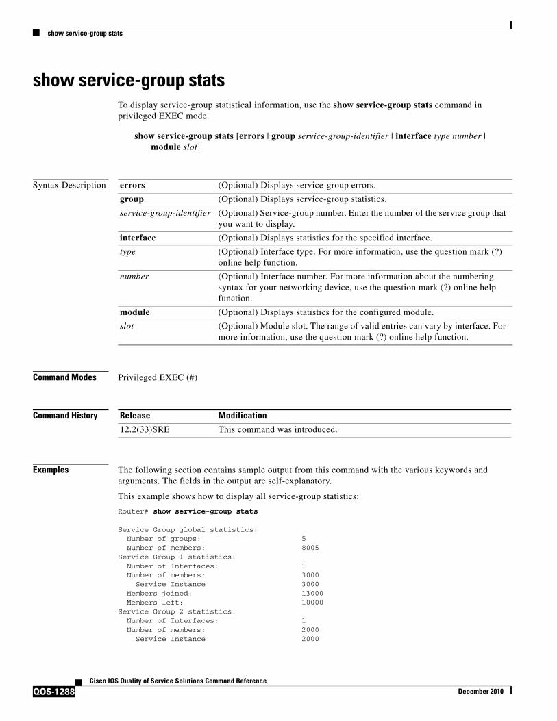
show service-group stats
QOS-1288Cisco IOS Quality of Service Solutions Command Reference
December 2010
show service-group statsTo display service-group statistical information, use the show service-group stats command in privileged EXEC mode.
show service-group stats [errors | group service-group-identifier | interface type number | module slot]
Syntax Description
Command Modes Privileged EXEC (#)
Command History
Examples The following section contains sample output from this command with the various keywords and arguments. The fields in the output are self-explanatory.
This example shows how to display all service-group statistics:
Router# show service-group stats
Service Group global statistics: Number of groups: 5 Number of members: 8005Service Group 1 statistics: Number of Interfaces: 1 Number of members: 3000 Service Instance 3000 Members joined: 13000 Members left: 10000Service Group 2 statistics: Number of Interfaces: 1 Number of members: 2000 Service Instance 2000
errors (Optional) Displays service-group errors.
group (Optional) Displays service-group statistics.
service-group-identifier (Optional) Service-group number. Enter the number of the service group that you want to display.
interface (Optional) Displays statistics for the specified interface.
type (Optional) Interface type. For more information, use the question mark (?) online help function.
number (Optional) Interface number. For more information about the numbering syntax for your networking device, use the question mark (?) online help function.
module (Optional) Displays statistics for the configured module.
slot (Optional) Module slot. The range of valid entries can vary by interface. For more information, use the question mark (?) online help function.
Release Modification
12.2(33)SRE This command was introduced.

show service-group stats
QOS-1289Cisco IOS Quality of Service Solutions Command Reference
December 2010
Members joined: 10000 Members left: 8000Service Group 3 statistics: Number of Interfaces: 1 Number of members: 3000 Service Instance 3000 Members joined: 9000 Members left: 6000Service Group 10 statistics: Number of Interfaces: 1 Number of members: 3 Service Instance 3 Members joined: 8003 Members left: 8000Service Group 20 statistics: Number of Interfaces: 1 Number of members: 2 Service Instance 2 Members joined: 8002 Members left: 8000
This example shows how to display all error statistics for all service groups:
Router# show service-group stats errors
Service Group 1 errors: Members rejected to join: Capability limitation: 0 Rejected by other software modules: 0 Failed to install service policy: 0 Database error: 0 Feature encountered error: 0 Invalid member type: 0 Invalid member id: 0Service Group 2 errors: Members rejected to join: Capability limitation: 0 Rejected by other software modules: 0 Failed to install service policy: 0 Database error: 0 Feature encountered error: 0 Invalid member type: 0 Invalid member id: 0Service Group 3 errors: Members rejected to join: Capability limitation: 0 Rejected by other software modules: 0 Failed to install service policy: 0 Database error: 0 Feature encountered error: 0 Invalid member type: 0 Invalid member id: 0
This example shows how to display statistics for service group 20:
Router# show service-group stats group 20
Service Group 20 statistics: Number of Interfaces: 1 Number of members: 2 Service Instance: 2 Members joined: 8002 Members left: 8000

show service-group stats
QOS-1290Cisco IOS Quality of Service Solutions Command Reference
December 2010
This example shows how to display statistics for the service-groups on a specific interface:
Router# show service-group stats interface gigabitethernet2/0/0
Interface GigabitEthernet2/0/0:Number of groups: 1Number of members: 2Group Members Service Instances
1 2 2
This example shows how to display statistics for the service-groups on module 3:
Router# show service-group stats module 3
Module 3: Number of groups: 3 Number of members: 8000 Group Interface Members Service Instances 1 GigabitEthernet3/1 3000 3000 2 GigabitEthernet3/1 2000 2000 3 GigabitEthernet3/1 3000 3000

show service-group traffic-stats
QOS-1291Cisco IOS Quality of Service Solutions Command Reference
December 2010
show service-group traffic-statsTo display service-group traffic statistics, use the show service-group traffic-stats command in privileged EXEC mode.
show service-group traffic-stats [group service-group-identifier]
Syntax Description
Command Default If a service-group number is not specified, information about all service groups is displayed.
Command Modes Privileged EXEC (#)
Command History
Usage Guidelines The show service-group traffic-stats command reports the combined total of the traffic statistics for all members of the service group.
How Traffic Statistics Are Collected
The traffic statistics for each member of a service group are accumulated and incremented periodically. Each time the statistics for the member are incremented, the group statistics are also incremented by the same amount. Note the following points:
• The service-group traffic statistics represent the grand total of the traffic statistics of all its members once they join the group. Traffic statistics collected prior to joining the group are not included. At any given time, therefore, it is possible that the total of the member traffic statistics may be larger than the group traffic statistics.
• The traffic statistics of a member can be cleared by using the clear ethernet service instance command. Clearing the traffic statistics of a member does not affect the group statistics in any way.
• Clearing the group traffic statistics does not clear the traffic statistics of the group member.
group (Optional) Displays service-group statistics.
service-group-identifier (Optional) Service-group identifier. Enter the number of an existing service group.
Release Modification
12.2(33)SRE This command was introduced.
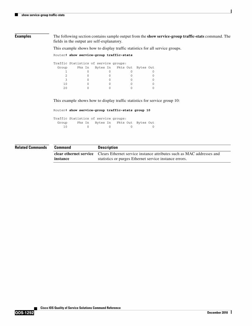
show service-group traffic-stats
QOS-1292Cisco IOS Quality of Service Solutions Command Reference
December 2010
Examples The following section contains sample output from the show service-group traffic-stats command. The fields in the output are self-explanatory.
This example shows how to display traffic statistics for all service groups.
Router# show service-group traffic-stats
Traffic Statistics of service groups: Group Pks In Bytes In Pkts Out Bytes Out 1 0 0 0 0 2 0 0 0 0 3 0 0 0 0 10 0 0 0 0 20 0 0 0 0
This example shows how to display traffic statistics for service group 10:
Router# show service-group traffic-stats group 10
Traffic Statistics of service groups: Group Pks In Bytes In Pkts Out Bytes Out 10 0 0 0 0
Related Commands Command Description
clear ethernet service instance
Clears Ethernet service instance attributes such as MAC addresses and statistics or purges Ethernet service instance errors.

show subscriber policy ppm-shim-db
QOS-1293Cisco IOS Quality of Service Solutions Command Reference
December 2010
show subscriber policy ppm-shim-dbTo display the total number of dynamically created template service policy maps and Net Effect policy maps on the router, use the show subscriber policy ppm-shim-db command in user EXEC or privileged EXEC mode.
show subscriber policy ppm-shim-db
Syntax Description This command has no arguments or keywords.
Command Modes User EXECPrivileged EXEC
Command History
Examples The following is sample output from the show subscriber policy ppm-shim-db command:
Router# show subscriber policy ppm-shim-dbTotal number of dynamically created policy = 10
The output fields are self-explanatory.
Release Modification
Cisco IOS Release XE 3.2S This command was introduced on the ASR 1000 Series Aggregation Services Routers.

show table-map
QOS-1294Cisco IOS Quality of Service Solutions Command Reference
December 2010
show table-mapTo display the configuration of a specified table map or all table maps, use the show table-map command in EXEC mode.
show table-map table-map-name
Syntax Description
Command Modes EXEC
Command History
Examples The sample output of the show table-map command shows the contents of a table map called “map 1”. In “map1”, a “to–from” relationship has been established and a default value has been defined. The fields for establishing the “to–from” mappings are further defined by the policy map in which the table map will be configured. (Configuring a policy map is the next logical step after creating a table map.)
For instance, a precedence or differentiated services code point (DSCP) value of 0 could be mapped to a class of service (CoS) value of 1, or vice versa, depending on the how the values are defined in the table map. Any values not explicitly defined in a “to–from” relationship will be set to a default value.
The following sample output of the show table-map command displays the contents of a table map called “map1”. In this table map, a packet-marking value of 0 is mapped to a packet-marking value of 1. All other packet-marking values are mapped to the default value 3.
Router# show table-map map1
Table Map map1 from 0 to 1 default 3
Table 233 describes the fields shown in the display.
table-map-name Name of table map used to map one packet-marking value to another. The name can be a maximum of 64 alphanumeric characters.
Release Modification
12.2(13)T This command was introduced.
Table 233 show table-map Field Descriptions
Field Description
Table Map The name of the table map being displayed.
from, to The values of the “to–from” relationship established by the table-map (value mapping) command and further defined by the policy map in which the table map will be configured.
default The default action to be used for any values not explicitly defined in a “to–from” relationship by the table-map (value mapping) command. If a default action is not specified in the table-map (value mapping) command, the default action is “copy”.

show table-map
QOS-1295Cisco IOS Quality of Service Solutions Command Reference
December 2010
Related Commands Command Description
policy-map Creates or modifies a policy map that can be attached to one or more interfaces to specify a service policy.
show policy-map Displays the configuration of all classes for a specified service policy map or all classes for all existing policy maps.
show policy-map class Displays the configuration for the specified class of the specified policy map.
table-map (value mapping)
Creates and configures a mapping table for mapping and converting one packet-marking value to another.

show tech-support rsvp
QOS-1296Cisco IOS Quality of Service Solutions Command Reference
December 2010
show tech-support rsvpTo generate a report of all Resource Reservation Protocol (RSVP)-related information, use the show tech-support rsvp command in privileged EXEC mode.
show tech-support rsvp
Syntax Description This command has no arguments or keywords.
Command Modes Privileged EXEC
Command History
Usage Guidelines This command is not required for normal use of the operating system. This command is useful when you contact technical support personnel with questions regarding RSVP. The show tech-support rsvp command generates a series of reports that can be useful to technical support personnel attempting to solve problems.
Any issues or caveats that apply to the show tech-support command also apply to this command. For example, the enable password, if configured, is not displayed in the output of the show running-config command.
Examples The show tech-support rsvp command is equivalent to issuing the following commands:
• show ip rsvp installed
• show ip rsvp interface
• show ip rsvp neighbor
• show ip rsvp policy cops
• show ip rsvp reservation
• show ip rsvp sender
• show running-config
• show version
For the specific examples, refer to the displays and descriptions for the individual commands for more information.
Release Modification
11.2 This command was introduced.
12.2(33)SRA This command was integrated into Cisco IOS Release 12.2(33)SRA.
12.2SX This command is supported in the Cisco IOS Release 12.2SX train. Support in a specific 12.2SX release of this train depends on your feature set, platform, and platform hardware.

show traffic-shape
QOS-1297Cisco IOS Quality of Service Solutions Command Reference
December 2010
show traffic-shape
Note Effective with Cisco IOS XE Release 2.6, Cisco IOS Release 15.0(1)S, and Cisco IOS Release 15.1(3)T, the show traffic-shape command is hidden. Although this command is still available in Cisco IOS software, the CLI interactive Help does not display it if you attempt to view it by entering a question mark at the command line.
This command will be completely removed in a future release, which means that you will need to use the appropriate replacement command (or sequence of commands). For more information (including a list of replacement commands), see the Legacy QoS Command Deprecation feature document in the Cisco IOS XE Quality of Service Solutions Configuration Guide or the Legacy QoS Command Deprecation feature document in the Cisco IOS Quality of Service Solutions Configuration Guide.
Note Effective with Cisco IOS XE Release 3.2S, the show traffic-shape command is replaced by a modular QoS CLI (MQC) command (or sequence of MQC commands). For the appropriate replacement command (or sequence of commands), see the Legacy QoS Command Deprecation feature document in the Cisco IOS XE Quality of Service Solutions Configuration Guide.
To display the current traffic-shaping configuration, use the show traffic-shape command in EXEC mode.
show traffic-shape [interface-type interface-number]
Syntax Description
Command Modes EXEC
Command History
interface-type (Optional) The type of the interface. If no interface is specified, traffic-shaping details for all configured interfaces are shown.
interface-number (Optional) The number of the interface.
Release Modification
11.2 This command was introduced.
12.2(33)SRA This command was integrated into Cisco IOS Release 12.2(33)SRA.
12.2SX This command is supported in the Cisco IOS Release 12.2SX train. Support in a specific 12.2SX release of this train depends on your feature set, platform, and platform hardware.
Cisco IOS XE Release 2.6
This command was modified. This command was hidden.
15.0(1)S This command was modified. This command was hidden.
15.1(3)T This command was modified. This command was hidden.
Cisco IOS XE Release 3.2S
This command was replaced by an MQC command (or sequence of MQC commands).

show traffic-shape
QOS-1298Cisco IOS Quality of Service Solutions Command Reference
December 2010
Usage Guidelines You must have first enabled traffic shaping using the traffic-shape rate, traffic-shape group, or frame-relay traffic-shaping command to display traffic-shaping information.
Examples The following is sample output from the show traffic-shape command:
Router# show traffic-shape
Interface Fa0/0 Access Target Byte Sustain Excess Interval Increment AdaptVC List Rate Limit bits/int bits/int (ms) (bytes) Active- 1000000 6250 25000 25000 25 3125 -
Table 234 describes the significant fields shown in the display.
Related Commands
Table 234 show traffic-shape Field Descriptions
Field Description
Interface Interface type and number.
VC Virtual circuit.
Note If you configure traffic shaping at a VC level instead of an interface level, a number appears in this field.
Access List Number of the access list, if one is configured.
Target Rate Rate that traffic is shaped to, in bits per second.
Byte Limit Maximum number of bytes sent per internal interval.
Sustain bits/int Configured sustained bits per interval.
Excess bits/int Configured excess bits in the first interval.
Interval (ms) Interval (in milliseconds) being used internally, which may be smaller than the committed burst divided by the committed information rate, if the router determines that traffic flow will be more stable with a smaller configured interval.
Increment (bytes) Number of bytes that will be sustained per internal interval.
Adapt Active Contains “BECN” if Frame Relay has backward explicit congestion notification (BECN) adaptation configured.
Command Description
frame-relay cir Specifies the incoming or outgoing committed information rate (CIR) for a Frame Relay virtual circuit.
frame-relay traffic-rate Configures all the traffic-shaping characteristics of a virtual circuit (VC) in a single command.
frame-relay traffic-shaping Enables both traffic shaping and per-VC queueing for all PVCs and SVCs on a Frame Relay interface.
show traffic-shape queue Displays information about the elements queued by traffic shaping at the interface level or the DLCI level.
show traffic-shape statisitcs Displays the current traffic-shaping statistics.
traffic-shape adaptive Configures a Frame Relay subinterface to estimate the available bandwidth when BECN signals are received.

show traffic-shape
QOS-1299Cisco IOS Quality of Service Solutions Command Reference
December 2010
traffic-shape fecn-adap Replies to messages with the FECN bit (which are set with TEST RESPONSE messages with the BECN bit set).
traffic-shape group Enables traffic shaping based on a specific access list for outbound traffic on an interface.
traffic-shape rate Enables traffic shaping for outbound traffic on an interface.
Command Description

show traffic-shape queue
QOS-1300Cisco IOS Quality of Service Solutions Command Reference
December 2010
show traffic-shape queue
Note Effective with Cisco IOS XE Release 2.6, Cisco IOS Release 15.0(1)S, and Cisco IOS Release 15.1(3)T, the show traffic-shape queue command is hidden. Although this command is still available in Cisco IOS software, the CLI interactive Help does not display it if you attempt to view it by entering a question mark at the command line.
This command will be completely removed in a future release, which means that you will need to use the appropriate replacement command (or sequence of commands). For more information (including a list of replacement commands), see the Legacy QoS Command Deprecation feature document in the Cisco IOS XE Quality of Service Solutions Configuration Guide or the Legacy QoS Command Deprecation feature document in the Cisco IOS Quality of Service Solutions Configuration Guide.
Note Effective with Cisco IOS XE Release 3.2S, the show traffic-shape queue command is replaced by a modular QoS CLI (MQC) command (or sequence of MQC commands). For the appropriate replacement command (or sequence of commands), see the Legacy QoS Command Deprecation feature document in the Cisco IOS XE Quality of Service Solutions Configuration Guide.
To display information about the elements queued by traffic shaping at the interface level or the data-link connection identifier (DLCI) level, use the show traffic-shape queue command in privileged EXEC mode.
show traffic-shape queue [interface-number [dlci dlci-number]]
Syntax Description
Command Modes Privileged EXEC
Command History
interface-number (Optional) The number of the interface.
dlci (Optional) The specific DLCI for which you wish to display information about queued elements.
dlci-number (Optional) The number of the DLCI.
Release Modification
11.2 This command was introduced.
12.0(3)XG This command was integrated into Cisco IOS Release 12.0(3)XG. The dlci argument was added.
12.0(4)T This command was integrated into Cisco IOS Release 12.0(4)T. The dlci argument was added.
12.0(5)T This command was modified to include information on the special voice queue that is created using the queue keyword of the frame-relay voice bandwidth command.
12.2(28)SB This command was modified to support hierarchical queueing framework (HQF) on Frame Relay (FR) interfaces or permanent virtual circuits (PVCs).

show traffic-shape queue
QOS-1301Cisco IOS Quality of Service Solutions Command Reference
December 2010
Usage Guidelines When no parameters are specified with this command, the output displays information for all interfaces and DLCIs containing queued elements. When a specific interface and DLCI are specified, information is displayed about the queued elements for that DLCI only.
When you use this command with HQF, no output displays.
Examples The following is sample output for the show traffic-shape queue command when weighted fair queueing is configured on the map class associated with DLCI 16:
Router# show traffic-shape queue Serial1/1 dlci 16
Traffic queued in shaping queue on Serial1.1 dlci 16 Queueing strategy: weighted fair Queueing Stats: 1/600/64/0 (size/max total/threshold/drops) Conversations 0/16 (active/max total) Reserved Conversations 0/2 (active/allocated) (depth/weight/discards) 1/4096/0 Conversation 5, linktype: ip, length: 608 source: 172.21.59.21, destination: 255.255.255.255, id: 0x0006, ttl: 255, TOS: 0 prot: 17, source port 68, destination port 67
The following is sample output for the show traffic-shape queue command when priority queueing is configured on the map class associated with DLCI 16:
Router# show traffic-shape queue Serial1/1 dlci 16
Traffic queued in shaping queue on Serial1.1 dlci 16 Queueing strategy: priority-group 4 Queueing Stats: low/1/80/0 (queue/size/max total/drops)
Packet 1, linktype: cdp, length: 334, flags: 0x10000008
The following is sample output for the show traffic-shape queue command when first-come, first-serve queueing is configured on the map class associated with DLCI 16:
Router# show traffic-shape queue Serial1/1 dlci 16
Traffic queued in shaping queue on Serial1.1 dlci 16 Queueing strategy: fcfs Queueing Stats: 1/60/0 (size/max total/drops)
Packet 1, linktype: cdp, length: 334, flags: 0x10000008
12.2(33)SRA This command was integrated into Cisco IOS Release 12.2(33)SRA.
12.2SX This command is supported in the Cisco IOS Release 12.2SX train. Support in a specific 12.2SX release of this train depends on your feature set, platform, and platform hardware.
Cisco IOS XE Release 2.6
This command was modified. This command was hidden.
15.0(1)S This command was modified. This command was hidden.
15.1(3)T This command was modified. This command was hidden.
Cisco IOS XE Release 3.2S
This command was replaced by an MQC command (or sequence of MQC commands).
Release Modification

show traffic-shape queue
QOS-1302Cisco IOS Quality of Service Solutions Command Reference
December 2010
The following is sample output for the show traffic-shape queue command displaying statistics for the special queue for voice traffic that is created automatically when the frame-relay voice bandwidth command is entered:
Router# show traffic-shape queue Serial1/1 dlci 45
Voice queue attached to traffic shaping queue on Serial1 dlci 45 ~~~~~~~~~~~~~~~~~~~~~~~~~~~~~~~~~~~~~~~~~~~~~~~~~~~~~~~~~~~~~~~~ Voice Queueing Stats: 0/100/0 (size/max/dropped) ~~~~~~~~~~~~~~~~~~~~~~~~~~~~~~~~~~~~~~~~~~~~~~~~ Traffic queued in shaping queue on Serial1 dlci 45 Queueing strategy: weighted fair Queueing Stats: 0/600/64/0 (size/max total/threshold/drops) Conversations 0/16 (active/max total) Reserved Conversations 0/2 (active/allocated)
Table 235 describes the significant fields shown in the display.
Table 235 show traffic-shape queue Field Descriptions
Field Description
Queueing strategy When Frame Relay Traffic Shaping (FRTS) is configured, the queueing type can be weighted fair, custom-queue, priority-group, or fcfs (first-come, first-serve), depending on what is configured on the Frame Relay map class for this DLCI. The default is fcfs for FRTS. When generic traffic shaping is configured, the only queueing type available is weighted fair queueing (WFQ).
Queueing Stats Statistics for the configured queueing strategy, as follows:
• size—Current size of the queue.
• max total—Maximum number of packets of all types that can be queued in all queues.
• threshold—For WFQ, the number of packets in the queue after which new packets for high-bandwidth conversations will be dropped.
• drops—Number of packets discarded during this interval.
Conversations active Number of currently active conversations.
Conversations max total Maximum allowed number of concurrent conversations.
Reserved Conversations active
Number of currently active conversations reserved for voice.
Reserved Conversations allocated
Maximum configured number of conversations reserved.
depth Number of packets currently queued.
weight Number used to classify and prioritize the packet.
discards Number of packets discarded from queues.
Packet Number of queued packet.
linktype Protocol type of the queued packet. (cdp = Cisco Discovery Protocol)
length Number of bytes in the queued packet.
flags Number of flag characters in the queued packet.
source Source IP address.

show traffic-shape queue
QOS-1303Cisco IOS Quality of Service Solutions Command Reference
December 2010
Related Commands
destination Destination IP address.
id Packet ID.
ttl Time to live count.
TOS IP type of service.
prot Layer 4 protocol number. Refer to RFC 943 for a list of protocol numbers. (17 = User Datagram Protocol (UDP))
source port Port number of source port.
destination port Port number of destination port.
Table 235 show traffic-shape queue Field Descriptions (continued)
Field Description
Command Description
show frame-relay fragment
Displays Frame Relay fragmentation details.
show frame-relay pvc Displays statistics about PVCs for Frame Relay interfaces.
show frame-relay vofr Displays details about FRF.11 subchannels being used on VoFR DLCIs.
show traffic-shape Displays the current traffic-shaping configuration.
show traffic-shape statistics
Displays the current traffic-shaping statistics.

show traffic-shape statistics
QOS-1304Cisco IOS Quality of Service Solutions Command Reference
December 2010
show traffic-shape statistics
Note Effective with Cisco IOS XE Release 2.6, Cisco IOS Release 15.0(1)S, and Cisco IOS Release 15.1(3)T, the show traffic-shape statistics command is hidden. Although this command is still available in Cisco IOS software, the CLI interactive Help does not display it if you attempt to view it by entering a question mark at the command line.
This command will be completely removed in a future release, which means that you will need to use the appropriate replacement command (or sequence of commands). For more information (including a list of replacement commands), see the Legacy QoS Command Deprecation feature document in the Cisco IOS XE Quality of Service Solutions Configuration Guide or the Legacy QoS Command Deprecation feature document in the Cisco IOS Quality of Service Solutions Configuration Guide.
Note Effective with Cisco IOS XE Release 3.2S, the show traffic-shape statistics command is replaced by a modular QoS CLI (MQC) command (or sequence of MQC commands). For the appropriate replacement command (or sequence of commands), see the Legacy QoS Command Deprecation feature document in the Cisco IOS XE Quality of Service Solutions Configuration Guide.
To display the current traffic-shaping statistics, use the show traffic-shape statistics command in EXEC mode.
show traffic-shape statistics [interface-type interface-number]
Syntax Description
Command Modes EXEC
Command History
interface-type (Optional) The type of the interface. If no interface is specified, traffic-shaping statistics for all configured interfaces are shown.
interface-number (Optional) The number of the interface.
Release Modification
11.2 This command was introduced.
12.2(33)SRA This command was integrated into Cisco IOS Release 12.2(33)SRA.
12.2SX This command is supported in the Cisco IOS Release 12.2SX train. Support in a specific 12.2SX release of this train depends on your feature set, platform, and platform hardware.
Cisco IOS XE Release 2.6
This command was modified. This command was hidden.
15.0(1)S This command was modified. This command was hidden.
15.1(3)T This command was modified. This command was hidden.
Cisco IOS XE Release 3.2S
This command was replaced by an MQC command (or sequence of MQC commands).

show traffic-shape statistics
QOS-1305Cisco IOS Quality of Service Solutions Command Reference
December 2010
Usage Guidelines You must have first enabled traffic shaping using the traffic-shape rate, traffic-shape group, or frame-relay traffic-shaping command to display traffic-shaping information.
Examples The following is sample output from the show traffic-shape statistics command:
Router# show traffic-shape statistics
Access Queue Packets Bytes Packets Bytes ShapingI/F List Depth Delayed Delayed ActiveEt0 101 0 2 180 0 0 noEt1 0 0 0 0 0 no
Table 236 describes the significant fields shown in the display.
Related Commands
Table 236 show traffic-shape statistics Field Descriptions
Field Description
I/F Interface.
Access List Number of the access list.
Queue Depth Number of messages in the queue.
Packets Number of packets sent through the interface.
Bytes Number of bytes sent through the interface.
Packets Delayed Number of packets sent through the interface that were delayed in the traffic-shaping queue.
Bytes Delayed Number of bytes sent through the interface that were delayed in the traffic-shaping queue.
Shaping Active Contains “yes” when timers indicate that traffic shaping is occurring and “no” if traffic shaping is not occurring.
Command Description
frame-relay traffic-shaping
Enables both traffic shaping and per-VC queueing for all PVCs and SVCs on a Frame Relay interface.
show interfaces Displays statistics for all interfaces configured on the router or access server.
show ip rsvp neighbor Displays RSVP-related interface information.
traffic-shape adaptive Configures a Frame Relay subinterface to estimate the available bandwidth when BECN signals are received.
traffic-shape group Enables traffic shaping based on a specific access list for outbound traffic on an interface.
traffic-shape rate Enables traffic shaping for outbound traffic on an interface.

show vrf
QOS-1306Cisco IOS Quality of Service Solutions Command Reference
December 2010
show vrfTo display the defined Virtual Private Network (VPN) routing and forwarding (VRF) instances, use the show vrf command in user EXEC or privileged EXEC mode.
show vrf [ipv4 | ipv6] [interface | brief | detail | id | select | lock] [vrf-name]
Syntax Description
Command Default If you do not specify any arguments or keywords, the command displays concise information about all configured VRFs.
Command Modes User EXEC (>)Privileged EXEC (#)
Command History
Usage Guidelines Use the show vrf command to display information about specified VRF instances or all VRF instances. Specify no arguments or keywords to display information on all VRF instances.
ipv4 (Optional) Displays IPv4 address family-type VRF instances.
ipv6 (Optional) Displays IPv6 address family-type VRF instances.
interface (Optional) Displays the interface associated with the specified VRF instances.
brief (Optional) Displays brief information about the specified VRF instances.
detail (Optional) Displays detailed information about the specified VRF instances.
id (Optional) Displays VPN-ID information for the specified VRF instances.
select (Optional) Displays selection information for the specified VRF instances.
lock (Optional) Displays VPN lock information for the specified VRF instances.
vrf-name (Optional) Name assigned to a VRF.
Release Modification
12.2(33)SRB This command was introduced.
12.2(33)SXH This command was integrated into Cisco IOS Release 12.2(33)SXH.
12.2(33)SB This command was integrated into Cisco IOS Release 12.2(33)SB.
12.4(20)T This command was integrated into Cisco IOS Release 12.4(20)T.
Cisco IOS XE Release 2.1
This command was integrated into Cisco IOS XE Release 2.1.
12.2(33)SRE This command was modified. When backup paths have been created either through the Prefix Independent Convergence or Best External feature, the output of the show vrf detail command displays the following line:
Prefix protection with additional path enabled
15.0(1)S This command was integrated into Cisco IOS Release 15.0(1)S.

show vrf
QOS-1307Cisco IOS Quality of Service Solutions Command Reference
December 2010
Examples The following sample output from the show vrf command displays brief information about all configured VRF instances:
Router# show vrf
Name Default RD Protocols Interfaces N1 100:0 ipv4,ipv6 V1 1:1 ipv4 Lo1 V2 2:2 ipv4,ipv6 Et0/1.1 Et0/1.2 Et0/1.3 V3 3:3 ipv4 Lo3 Et0/1.4
Table 237 describes the significant fields shown in the display.
The following sample output from the show vrf command with the detail keyword displays information for a VRF named cisco:.
Router# show vrf detail
VRF cisco1; default RD 100:1; default VPNID <not set>Interfaces:
Ethernet0/0 Loopback10Address family ipv4 (Table ID = 0x1):
Connected addresses are not in global routing tableExport VPN route-target communities
RT:100:1Import VPN route-target communities
RT:100:1No import route-mapNo export route-mapVRF label distribution protocol: not configured
Address family ipv6 (Table ID = 0xE000001):Connected addresses are not in global routing tableExport VPN route-target communities
RT:100:1Import VPN route-target communities
RT:100:1No import route-mapNo export route-mapVRF label distribution protocol: not configured
Table 238 describes the significant fields shown in the display.
Table 237 show vrf Field Descriptions
Field Description
Name Name of the VRF instance.
Default RD The default route distinguisher (RD) for the specified VRF instances.
Protocols The address family protocol type for the specified VRF instance.
Interfaces The network interface associated with the VRF instance.

show vrf
QOS-1308Cisco IOS Quality of Service Solutions Command Reference
December 2010
The following example displays output from the show vrf detail command when backup paths have been created either through the Prefix Independent Convergence or Best External feature. The output of the show vrf detail command displays the following line:
Prefix protection with additional path enabled
Router# show vrf detail
VRF vpn1 (VRF Id = 1); default RD 1:1; default VPNID <not set> Interfaces: Et1/1 Address family ipv4 (Table ID = 1 (0x1)): Export VPN route-target communities RT:1:1 Import VPN route-target communities RT:1:1 No import route-map No export route-map VRF label distribution protocol: not configured VRF label allocation mode: per-prefix Prefix protection with additional path enabledAddress family ipv6 not active.
The following sample output from the show vrf lock command displays VPN lock information:
Router# show vrf lock
VRF Name: Mgmt-intf; VRF id = 4085 (0xFF5)VRF lock count: 3 Lock user: RTMGR, lock user ID: 2, lock count per user: 1 Caller PC tracebacks: Trace backs: :10000000+44DAEB4 :10000000+21E83AC :10000000+45A9F04 :108 Lock user: CEF, lock user ID: 4, lock count per user: 1 Caller PC tracebacks: Trace backs: :10000000+44DAEB4 :10000000+21E83AC :10000000+45A9F04 :10C Lock user: VRFMGR, lock user ID: 1, lock count per user: 1 Caller PC tracebacks: Trace backs: :10000000+44DAEB4 :10000000+21E83AC :10000000+21EAD18 :10CVRF Name: vpn1; VRF id = 1 (0x1)VRF lock count: 3 Lock user: RTMGR, lock user ID: 2, lock count per user: 1 Caller PC tracebacks: Trace backs: :10000000+44DAEB4 :10000000+21E83AC :10000000+45A9F04 :10C Lock user: CEF, lock user ID: 4, lock count per user: 1 Caller PC tracebacks: Trace backs: :10000000+44DAEB4 :10000000+21E83AC :10000000+45A9F04 :100
Table 238 show vrf detail Field Descriptions
Field Description
default RD 100:1 The RD given to this VRF.
Interfaces: Interfaces to which the VRF is attached.
Export VPN route-target communities
RT:100:1
Route-target VPN extended communities to be exported.
Import VPN route-target communities
RT:100:1
Route-target VPN extended communities to be imported.

show vrf
QOS-1309Cisco IOS Quality of Service Solutions Command Reference
December 2010
Lock user: VRFMGR, lock user ID: 1, lock count per user: 1 Caller PC tracebacks: Trace backs: :10000000+44DAEB4 :10000000+21E83AC :10000000+21EAD18 :10C
Related Commands Command Description
vrf definition Configures a VRF routing table instance and enters VRF configuration mode.
vrf forwarding Associates a VRF instance with an interface or subinterface.

show wrr-queue
QOS-1310Cisco IOS Quality of Service Solutions Command Reference
December 2010
show wrr-queueTo display the queue information that is serviced on a weighted round-robin (WRR) scheduling basis, use the show wrr-queue command in user EXEC or privileged EXEC mode.
show wrr-queue {bandwidth | cos-map}
Syntax Description
Command Modes User EXEC (>)Privileged EXEC (#)
Command History
Usage Guidelines Use this command to display the queue information that is scheduled for servicing on WRR basis. WRR is a type of scheduling that prevents low-priority queues from being completely neglected during periods of high-priority traffic. The WRR scheduler transmits some packets from each queue in turn. The number of packets that the scheduler transmits corresponds to the relative importance of the queue.
Examples The following is sample output from the show wrr-queue command. The fields are self-explanatory.
Router# show wrr-queue bandwidth
wrr-queue bandwidth for Etherswitch HWIC is:WRR Queue : 1 2 3 4
Bandwidth : 1 2 4 8
Router# show wrr-queue cos-map
wrr-queue cos_map for Etherswitch HWIC is:CoS Value : 0 1 2 3 4 5 6 7
Priority Queue : 1 1 2 2 3 3 4 4
bandwidth Displays the bandwidth information.
cos-map Displays the class of service (CoS) map information.
Release Modification
12.4(24)T This command was introduced in a release earlier than Cisco IOS Release 12.4(24)T.
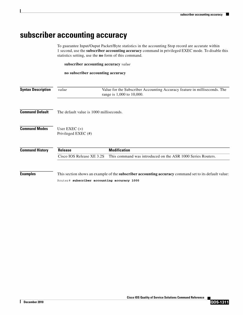
subscriber accounting accuracy
QOS-1311Cisco IOS Quality of Service Solutions Command Reference
December 2010
subscriber accounting accuracyTo guarantee Input/Ouput Packet/Byte statistics in the accounting Stop record are accurate within 1 second, use the subscriber accounting accuracy command in privileged EXEC mode. To disable this statistics setting, use the no form of this command.
subscriber accounting accuracy value
no subscriber accounting accuracy
Syntax Description
Command Default The default value is 1000 milliseconds.
Command Modes User EXEC (>)Privileged EXEC (#)
Command History
Examples This section shows an example of the subscriber accounting accuracy command set to its default value:
Router# subscriber accounting accuracy 1000
value Value for the Subscriber Accounting Accuracy feature in milliseconds. The range is 1,000 to 10,000.
Release Modification
Cisco IOS Release XE 3.2S This command was introduced on the ASR 1000 Series Routers.
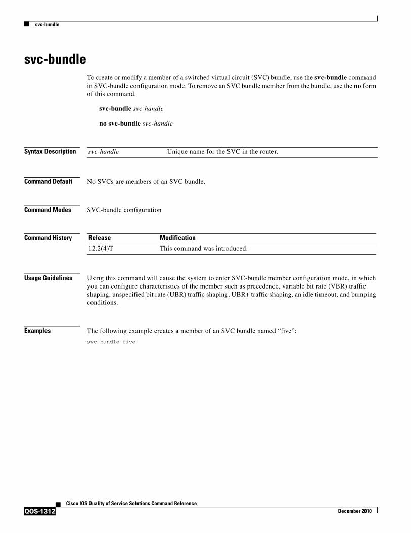
svc-bundle
QOS-1312Cisco IOS Quality of Service Solutions Command Reference
December 2010
svc-bundleTo create or modify a member of a switched virtual circuit (SVC) bundle, use the svc-bundle command in SVC-bundle configuration mode. To remove an SVC bundle member from the bundle, use the no form of this command.
svc-bundle svc-handle
no svc-bundle svc-handle
Syntax Description
Command Default No SVCs are members of an SVC bundle.
Command Modes SVC-bundle configuration
Command History
Usage Guidelines Using this command will cause the system to enter SVC-bundle member configuration mode, in which you can configure characteristics of the member such as precedence, variable bit rate (VBR) traffic shaping, unspecified bit rate (UBR) traffic shaping, UBR+ traffic shaping, an idle timeout, and bumping conditions.
Examples The following example creates a member of an SVC bundle named “five”:
svc-bundle five
svc-handle Unique name for the SVC in the router.
Release Modification
12.2(4)T This command was introduced.

table-map (value mapping)
QOS-1313Cisco IOS Quality of Service Solutions Command Reference
December 2010
table-map (value mapping)To create and configure a mapping table for mapping and converting one packet-marking value to another, use the table-map (value mapping) command in global configuration mode. To disable the use of this table map, use the no form of this command.
table-map table-map-name map from from-value to to-value [default default-value-or-action]
no table-map table-map-name map from from-value to to-value [default default-value-or-action]
Syntax Description
Defaults The default keyword and default-value-or-action argument sets the default value (or action) to be used if a value if not explicitly designated.
If you configure a table map but you do not specify a default-value-or-action argument for the default keyword, the default action is “copy”.
Command Modes Global configuration
Command History
Usage Guidelines This command allows you to create a mapping table. The mapping table, a type of conversion chart, is used for establishing a “to–from” relationship between packet-marking types or categories. For example, a mapping table can be used to establish a “to–from” relationship between the following packet-marking categories:
• Class of service (CoS)
• Precedence
table-map-name Name of table map to be created. The name can be a maximum of 64 alphanumeric characters.
map from Indicates that a “map from” value will be used.
from-value The “map from” value of the packet-marking category. The value range varies according to the packet-marking category from which you want to map and convert. For more information, see the “Usage Guidelines” section below.
to Indicates that a “map to” value will be used.
to-value The “map to” value of the packet-marking category. The value range varies according to the packet-marking category to which you want to map and convert. For more information, see the “Usage Guidelines” section below.
default (Optional) Indicates that a default value or action will be used.
default-value-or-action (Optional) The default value or action to be used if a “to–from” relationship has not been explicitly configured. Default actions are “ignore” and “copy”. If neither action is specified, “copy” is used.
Release Modification
12.2(13)T This command was introduced.

table-map (value mapping)
QOS-1314Cisco IOS Quality of Service Solutions Command Reference
December 2010
• Differentiated services code point (DSCP)
• Quality of service (QoS) group
• Multiprotocol Label Switching (MPLS) experimental (EXP) imposition
• MPLS EXP topmost
When configuring the table map, you must specify the packet-marking values to be used in the conversion. The values you can enter vary by packet-marking category.
Table 239 lists the valid value ranges you can enter for each packet-marking category.
Examples In the following example, the table-map (value mapping) command has been configured to create a table map called “map1”. In “map1”, two “to–from” relationships have been established and a default value has been defined. The fields for establishing the “to–from” mappings are further defined by the policy map in which the table map will be configured. (Configuring a policy map is the next logical step after creating a table map.)
For instance, a precedence or DSCP value of 0 could be mapped to a CoS value of 0, or vice versa, depending on the how the table map is configured. Any values not explicitly defined in a “to–from” relationship will be set to a default value.
Router(config)# table-map map1Router(config-tablemap)# map from 0 to 0Router(config-tablemap)# map from 2 to 1Router(config-tablemap)# default 3Router(config-tablemap)# end
Related Commands
Table 239 Valid Value Ranges
Packet-Marking Category Value Ranges
CoS Specific IEEE 802.1Q number in the range from 0 to 7.
Precedence Number in the range from 0 to 7.
DSCP Number in the range from 0 to 63.
QoS Group Number in the range from 0 to 99.
MPLS EXP imposition Number in the range from 0 to 7.
MPLS EXP topmost Number in the range from 0 to 7.
Command Description
policy-map Creates or modifies a policy map that can be attached to one or more interfaces to specify a service policy.
show policy-map Displays the configuration of all classes for a specified service policy map or all classes for all existing policy maps.
show policy-map class Displays the configuration for the specified class of the specified policy map.
show policy-map interface
Displays the packet statistics of all classes that are configured for all service policies either on the specified interface or subinterface or on a specific PVC on the interface.
show table-map Displays the configuration of a specified table map or all table maps.

tcp
QOS-1315Cisco IOS Quality of Service Solutions Command Reference
December 2010
tcpTo enable Transmission Control Protocol (TCP) header compression within an IP Header Compression (IPHC) profile, use the tcp command in IPHC-profile configuration mode. To disable TCP header compression, use the no form of this command.
tcp
no tcp
Syntax Description This command has no arguments or keywords.
Command Default TCP header compression is enabled.
Command Modes IPHC-profile configuration
Command History
Usage Guidelines Intended for Use with IPHC Profiles
The tcp command is intended for use as part of an IPHC profile. An IPHC profile is used to enable and configure header compression on your network. For more information about using IPHC profiles to configure header compression, see the “Header Compression” module and the “Configuring Header Compression Using IPHC Profiles” module of the Cisco IOS Quality of Service Solutions Configuration Guide, Release 12.4T.
Examples The following is an example of an IPHC profile called profile1. In this example, TCP header compression has been enabled.
Router> enableRouter# configure terminalRouter(config)# iphc-profile profile1 van-jacobsonRouter(config-iphcp)# tcpRouter(config-iphcp)# end
Related Commands
Release Modification
12.4(9)T This command was introduced.
Command Description
iphc-profile Creates an IPHC profile.
tcp contexts
QOS-1316Cisco IOS Quality of Service Solutions Command Reference
December 2010
tcp contextsTo set the number of contexts available for Transmission Control Protocol (TCP) header compression, use the tcp contexts command in IPHC-profile configuration mode. To remove the number of previously configured contexts, use the no form of this command.
tcp contexts {absolute number-of-contexts | kbps-per-context kbps}
no tcp contexts
Syntax Description
Command Default The tcp contexts command calculates the number of contexts on the basis of bandwidth and allocates 4 kbps per context.
Command Modes IPHC-profile configuration
Command History
Usage Guidelines Use the tcp contexts command to set the number of contexts available for TCP header compression. A context is the state that the compressor uses to compress a header and that the decompressor uses to decompress a header. The context is the uncompressed version of the last header sent and includes information used to compress and decompress the packet.
Intended for Use with IPHC Profiles
The tcp contexts command is intended for use as part of an IPHC profile. An IPHC profile is used to enable and configure header compression on your network. For more information about using IPHC profiles to configure header compression, see the “Header Compression” module and the “Configuring Header Compression Using IPHC Profiles” module of the Cisco IOS Quality of Service Solutions Configuration Guide, Release 12.4T.
Setting the Number of Contexts as an Absolute Number
The tcp contexts command allows you to set the number of contexts as an absolute number. To set the number of contexts as an absolute number, enter a number between 1 and 256.
absolute Indicates that the maximum number of compressed TCP contexts will be based on a fixed (absolute) number.
number-of-contexts Number of TCP contexts. Range is from 1 to 256.
kbps-per-context Indicates that the maximum number of compressed TCP contexts will be based on available bandwidth.
kbps Number of kbps to allow for each context. Range is from 1 to 100.
Release Modification
12.4(9)T This command was introduced.
tcp contexts
QOS-1317Cisco IOS Quality of Service Solutions Command Reference
December 2010
Calculating the Number of Contexts on the Basis of Bandwidth
The tcp contexts command can calculate the number of contexts on the basis of the bandwidth available on the network link to which the IPHC profile is applied.
To have the number of contexts calculated on the basis of the available bandwidth, enter the kbps-per-context keyword followed by a value for the kbps argument The command divides the available bandwidth by the kbps specified. For example, if the bandwidth of the network link is 2000 kbps, and you enter 10 for the kbps argument, the command calculates 200 contexts.
Examples The following is an example of an IPHC profile called profile2. In this example, the number of TCP contexts has been set to 75.
Router> enableRouter# configure terminalRouter(config)# iphc-profile profile2 van-jacobsonRouter(config-iphcp)# tcp contexts absolute 75Router(config-iphcp)# end
Related Commands Command Description
iphc-profile Creates an IPHC profile.

traffic-shape adaptive
QOS-1318Cisco IOS Quality of Service Solutions Command Reference
December 2010
traffic-shape adaptiveTo configure a Frame Relay subinterface to estimate the available bandwidth when backward explicit congestion notification (BECN) signals are received, use the traffic-shape adaptive interface configuration command in interface configuration mode. To disregard the BECN signals and not estimate the available bandwidth, use the no form of this command.
traffic-shape adaptive bit-rate
no traffic-shape adaptive
Syntax Description
Command Default Bandwidth is not estimated when BECN signals are received.
Command Modes Interface configuration
Command History
Usage Guidelines This command specifies the boundaries in which traffic will be shaped when BECN signals are received. You must enable traffic shaping on the interface with the traffic-shape rate or traffic-shape group command before you can use the traffic-shape adaptive command.
The bit rate specified for the traffic-shape rate command is the upper limit, and the bit rate specified for the traffic-shape adaptive command is the lower limit to which traffic is shaped when BECN signals are received on the interface. The rate actually shaped to will be between these two bit rates.
You should configure this command and the traffic-shape fecn-adapt command on both ends of the connection to ensure adaptive traffic shaping over the connection, even when traffic is flowing primarily in one direction. The traffic-shape fecn-adapt command configures the router to reflect forward explicit congestion notification (FECN) signals as BECN signals.
Examples The following example configures traffic shaping on serial interface 0.1 with an upper limit of 128 kbps and a lower limit of 64 kbps. This configuration allows the link to run from 64 to 128 kbps, depending on the congestion level.
interface serial 0encapsulation-frame-relay
interface serial 0.1
bit-rate Lowest bit rate that traffic is shaped to, in bits per second. The default bit rate value is 0.
Release Modification
11.2 This command was introduced.
12.2(33)SRA This command was integrated into Cisco IOS Release 12.2(33)SRA.
12.2SX This command is supported in the Cisco IOS Release 12.2SX train. Support in a specific 12.2SX release of this train depends on your feature set, platform, and platform hardware.

traffic-shape adaptive
QOS-1319Cisco IOS Quality of Service Solutions Command Reference
December 2010
traffic-shape rate 128000traffic-shape adaptive 64000traffic-shape fecn-adapt
Related Commands Command Description
show traffic-shape Displays the current traffic-shaping configuration.
show traffic-shape statistics Displays the current traffic-shaping statistics.
traffic-shape fecn-adapt Replies to messages with the FECN bit (which are set with TEST RESPONSE messages with the BECN bit set).
traffic-shape group Enables traffic shaping based on a specific access list for outbound traffic on an interface.
traffic-shape rate Enables traffic shaping for outbound traffic on an interface.

traffic-shape fecn-adapt
QOS-1320Cisco IOS Quality of Service Solutions Command Reference
December 2010
traffic-shape fecn-adaptTo reply to messages with the forward explicit congestion notification (FECN) bit (which are sent with TEST RESPONSE messages with the BECN bit set), use the traffic-shape fecn-adapt command in interface configuration mode. To stop backward explicit congestion notification (BECN) signal generation, use the no form of this command.
traffic-shape fecn-adapt
no traffic-shape fecn-adapt
Syntax Description This command has no arguments or keywords.
Command Default Traffic shaping is disabled.
Command Modes Interface configuration (config-if)
Command History
Usage Guidelines Enable traffic shaping on the interface with the traffic-shape rate or traffic-shape group command. FECN is available only when traffic shaping is configured.
Use this command to reflect FECN bits as BECN bits. Reflecting FECN bits as BECN bits notifies the sending DTE that it is transmitting at a rate too fast for the DTE to handle. Use the traffic-shape adaptive command to configure the router to adapt its transmission rate when it receives BECN signals.
You should configure this command and the traffic-shape adaptive command on both ends of the connection to ensure adaptive traffic shaping over the connection, even when traffic is flowing primarily in one direction.
Examples The following example configures traffic shaping on serial interface 0.1 with an upper limit of 128 kbps and a lower limit of 64 kbps. This configuration allows the link to run from 64 to 128 kbps, depending on the congestion level. The router reflects FECN signals as BECN signals.
interface serial 0encapsulation-frame-relay
interface serial 0.1traffic-shape rate 128000traffic-shape adaptive 64000traffic-shape fecn-adapt
Release Modification
11.2 This command was introduced.
12.2(33)SRA This command was integrated into Cisco IOS Release 12.2(33)SRA.
12.2SX This command is supported in the Cisco IOS Release 12.2SX train. Support in a specific 12.2SX release of this train depends on your feature set, platform, and platform hardware.

traffic-shape fecn-adapt
QOS-1321Cisco IOS Quality of Service Solutions Command Reference
December 2010
Related Commands Command Description
show traffic-shape Displays the current traffic-shaping configuration.
show traffic-shape statistics Displays the current traffic-shaping statistics.
traffic-shape adaptive Configures a Frame Relay subinterface to estimate the available bandwidth when BECN signals are received.
traffic-shape group Enables traffic shaping based on a specific access list for outbound traffic on an interface.
traffic-shape rate Enables traffic shaping for outbound traffic on an interface.

traffic-shape group
QOS-1322Cisco IOS Quality of Service Solutions Command Reference
December 2010
traffic-shape groupTo enable traffic shaping based on a specific access list for outbound traffic on an interface, use the traffic-shape group command in interface configuration mode. To disable traffic shaping on the interface for the access list, use the no form of this command.
traffic-shape group access-list bit-rate [burst-size [excess-burst-size]]
no traffic-shape group access-list
Syntax Description
Command Default Disabled
Command Modes Interface configuration
Command History
Usage Guidelines Generic traffic shaping is not supported on ISDN and dialup interfaces. It is also not supported on nongeneric routing encapsulation tunnel interfaces. Traffic shaping is not supported with flow switching.
Traffic shaping uses queues to limit surges that can congest a network. Data is buffered and then sent into the network in regulated amounts to ensure that traffic will fit within the promised traffic envelope for the particular connection.
access-list Number of the access list that controls the packets that traffic shaping is applied to on the interface. Access list numbers can be numbers from 1 to 2699.
bit-rate Bit rate that traffic is shaped to, in bits per second. This is the access bit rate that you contract with your service provider, or the service levels you intend to maintain. Bit rates can be numbers in the range of 8000 to 100000000 bps.
burst-size (Optional) Sustained number of bits that can be sent per interval. On Frame Relay interfaces, this is the Committed Burst size contracted with your service provider. Valid entries are numbers in the range of 0 to 100000000.
excess-burst-size (Optional) Maximum number of bits that can exceed the burst size in the first interval in a congestion event. On Frame Relay interfaces, this is the Excess Burst size contracted with your service provider. Valid entries are numbers in the range of 0 to 100000000. The default is equal to the burst-size argument.
Release Modification
11.2 This command was introduced.
12.2(33)SRA This command was integrated into Cisco IOS Release 12.2(33)SRA.
12.2SX This command is supported in the Cisco IOS Release 12.2SX train. Support in a specific 12.2SX release of this train depends on your feature set, platform, and platform hardware.

traffic-shape group
QOS-1323Cisco IOS Quality of Service Solutions Command Reference
December 2010
The traffic-shape group command allows you to specify one or more previously defined access list to shape traffic on the interface. You must specify one traffic-shape group command for each access list on the interface.
The traffic-shape group command supports both standard and extended access lists.
Use traffic shaping if you have a network with differing access rates or if you are offering a subrate service. You can configure the values according to your contract with your service provider or the service levels you intend to maintain.
An interval is calculated as follows:
• If the burst-size is not equal to zero, the interval is the burst-size divided by the bit-rate.
• If the burst-size is zero, the interval is the excess-burst-size divided by the bit-rate.
Traffic shaping is supported on all media and encapsulation types on the router. To perform traffic shaping on Frame Relay virtual circuits, you can also use the frame-relay traffic-shaping command. For more information on Frame Relay Traffic Shaping, refer to the “Configuring Frame Relay” chapter in the Cisco IOS Wide-Area Networking Configuration Guide.
If traffic shaping is performed on a Frame Relay network with the traffic-shape rate command, you can also use the traffic-shape adaptive command to specify the minimum bit rate to which the traffic is shaped.
Examples The following example enables traffic that matches access list 101 to be shaped to a certain rate and traffic matching access list 102 to be shaped to another rate on the interface:
interface serial 1traffic-shape group 101 128000 16000 8000traffic-shape group 102 130000 10000 1000
Related Commands Command Description
access-list (IP Standard) Defines a standard IP access list.
show traffic-shape Displays the current traffic-shaping configuration.
show traffic-shape statistics Displays the current traffic-shaping statistics.
traffic-shape adaptive Configures a Frame Relay subinterface to estimate the available bandwidth when BECN signals are received.
traffic-shape fecn-adapt Replies to messages with the FECN bit (which are set with TEST RESPONSE messages with the BECN bit set).
traffic-shape rate Enables traffic shaping for outbound traffic on an interface.

traffic-shape rate
QOS-1324Cisco IOS Quality of Service Solutions Command Reference
December 2010
traffic-shape rateTo enable traffic shaping for outbound traffic on an interface, use the traffic-shape rate command in interface configuration mode. To disable traffic shaping on the interface, use the no form of this command.
traffic-shape rate bit-rate [burst-size [excess-burst-size]] [buffer-limit]
no traffic-shape rate
Syntax Description
Command Default Traffic shaping for outbound traffic is not enabled.
Command Modes Interface configuration
Command History
Usage Guidelines Generic traffic shaping is not supported on ISDN and dialup interfaces. Is is also not supported on nongeneric routing encapsulation tunnel interfaces. Traffic shaping is not supported with flow switching.
Traffic shaping uses queues to limit surges that can congest a network. Data is buffered and then sent into the network in regulated amounts to ensure that traffic will fit within the promised traffic envelope for the particular connection.
bit-rate Bit rate that traffic is shaped to, in bits per second. This is the access bit rate that you contract with your service provider, or the service levels you intend to maintain. Bit rates can be in the range of 8000 to 100000000 bps.
burst-size (Optional) Sustained number of bits that can be sent per interval. On Frame Relay interfaces, this is the Committed Burst size contracted with your service provider. Valid entries are numbers in the range of 0 to 100000000.
excess-burst-size (Optional) Maximum number of bits that can exceed the burst size in the first interval in a congestion event. On Frame Relay interfaces, this is the Excess Burst size contracted with your service provider. Valid entries are numbers in the range of 0 to 100000000. The default is equal to the burst-size argument.
buffer-limit (Optional) Maximum buffer limit in bps. Valid entries are numbers in the range of 0 to 4096.
Release Modification
11.2 This command was introduced.
12.2(33)SRA This command was integrated into Cisco IOS Release 12.2(33)SRA.
12.2SX This command is supported in the Cisco IOS Release 12.2SX train. Support in a specific 12.2SX release of this train depends on your feature set, platform, and platform hardware.
12.4(18e) This command was modified to prevent simultaneous configuration of legacy traffic-shaping and MQC shaping on the same interface.
traffic-shape rate
QOS-1325Cisco IOS Quality of Service Solutions Command Reference
December 2010
Use traffic shaping if you have a network with differing access rates or if you are offering a subrate service. You can configure the values according to your contract with your service provider or the service levels you intend to maintain.
An interval is calculated as follows:
• If the burst-size is not equal to zero, the interval is the burst-size divided by the bit-rate.
• If the burst-size is zero, the interval is the excess-burst-size divided by the bit-rate.
Traffic shaping is supported on all media and encapsulation types on the router. To perform traffic shaping on Frame Relay virtual circuits, you can also use the frame-relay traffic-shaping command. For more information on Frame Relay Traffic Shaping, refer to the “Configuring Frame Relay” chapter in the Cisco IOS Wide-Area Networking Configuration Guide.
If traffic shaping is performed on a Frame Relay network with the traffic-shape rate command, you can also use the traffic-shape adaptive command to specify the minimum bit rate to which the traffic is shaped.
Note Beginning in Cisco IOS Release 12.4(18e), you cannot configure the traffic-shape rate and MQC shaping on the same interface at the same time. You must remove the traffic-shape rate configured on the interface before you attach the service policy. For example, if you try to enter the service-policy {input | output} policy-map-name command when the traffic-shape rate command is already in effect, this message is displayed: Remove traffic-shape rate configured on the interface before attaching the service-policy.
If the MQC shaper is attached first, and you enter the legacy traffic-shape rate command on the same interface, the command is rejected and an error message is displayed.
Examples The following example enables traffic shaping on serial interface 0 using the bandwidth required by the service provider:
interface serial 0traffic-shape rate 128000 16000 8000
Related Commands Command Description
show traffic-shape Displays the current traffic-shaping configuration.
show traffic-shape statistics Displays the current traffic-shaping statistics.
traffic-shape adaptive Configures a Frame Relay subinterface to estimate the available bandwidth when BECN signals are received.
traffic-shape fecn-adapt Replies to messages with the FECN bit (which are set with TEST RESPONSE messages with the BECN bit set).
traffic-shape group Enables traffic shaping based on a specific access list for outbound traffic on an interface.

trust
QOS-1326Cisco IOS Quality of Service Solutions Command Reference
December 2010
trustTo define a trust state for traffic that is classified through the class policy-map configuration command, use the trust command in policy-map class configuration mode. To return to the default setting, use the no form of this command.
trust [cos | dscp | precedence]
no trust [cos | dscp | precedence]
Syntax Description
Command Default The action is not trusted.
Command Modes Policy-map class configuration (config-pmap-c)
Command History
Usage Guidelines Use this command to distinguish the quality of service (QoS) trust behavior for certain traffic from other traffic. For example, inbound traffic with certain DSCP values can be trusted. You can configure a class map to match and trust the DSCP values in the inbound traffic.
Trust values set with this command supersede trust values set with the qos trust interface configuration command.
If you specify the trust cos command, QoS uses the received or default port CoS value and the CoS-to-DSCP map to generate a DSCP value for the packet.
If you specify the trust dscp command, QoS uses the DSCP value from the ingress packet. For non-IP packets that are tagged, QoS uses the received CoS value; for non-IP packets that are untagged, QoS uses the default port CoS value. In either case, the DSCP value for the packet is derived from the CoS-to-DSCP map.
cos (Optional) Classifies an ingress packet by using the packet class of service (CoS) value. For an untagged packet, the port default CoS value is used.
dscp (Optional) Classifies an ingress packet by using the packet differentiated services code point (DSCP) values (most significant 6 bits of the 8-bit service-type field). For a non-IP packet, the packet CoS value is used if the packet is tagged. If the packet is untagged, the default port CoS value is used to map CoS to DSCP.
precedence (Optional) Classifies the precedence of the ingress packet.
Release Modification
12.2(14)SX This command was introduced on the Catalyst 6500 series.
12.2(33)SRA This command was implemented on the Catalyst 7600 series.
trust
QOS-1327Cisco IOS Quality of Service Solutions Command Reference
December 2010
Examples The following example shows how to define a port trust state to trust inbound DSCP values for traffic classified with “class1”:
Router# configure terminalRouter(config)# policy-map policy1Router(config-pmap)# class class1Router(config-pmap-c)# trust dscpRouter(config-pmap-c)# police 1000000 20000 exceed-action policed-dscp-transmitRouter(config-pmap-c)# endRouter#
You can verify your settings by entering the show policy-map privileged EXEC command.
Related Commands Command Description
class Specifies the name of the class whose traffic policy you want to create or change.
police Configures the Traffic Policing feature.
policy-map Creates a policy map that can be attached to multiple ports to specify a service policy and enters policy-map configuration mode.
set Marks IP traffic by setting a CoS, DSCP, or IP-precedence in the packet.
show policy-map Displays information about the policy map.
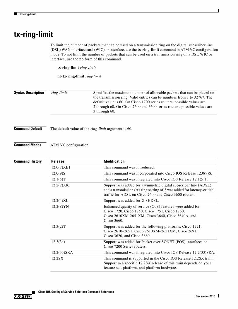
tx-ring-limit
QOS-1328Cisco IOS Quality of Service Solutions Command Reference
December 2010
tx-ring-limitTo limit the number of packets that can be used on a transmission ring on the digital subscriber line (DSL) WAN interface card (WIC) or interface, use the tx-ring-limit command in ATM VC configuration mode. To not limit the number of packets that can be used on a transmission ring on a DSL WIC or interface, use the no form of this command.
tx-ring-limit ring-limit
no tx-ring-limit ring-limit
Syntax Description
Command Default The default value of the ring-limit argument is 60.
Command Modes ATM VC configuration
Command History
ring-limit Specifies the maximum number of allowable packets that can be placed on the transmission ring. Valid entries can be numbers from 1 to 32767. The default value is 60. On Cisco 1700 series routers, possible values are 2 through 60. On Cisco 2600 and 3600 series routers, possible values are 3 through 60.
Release Modification
12.0(7)XE1 This command was introduced.
12.0(9)S This command was incorporated into Cisco IOS Release 12.0(9)S.
12.1(5)T This command was integrated into Cisco IOS Release 12.1(5)T.
12.2(2)XK Support was added for asymmetric digital subscriber line (ADSL), and a transmission (tx) ring setting of 3 was added for latency-critical traffic for ADSL on Cisco 2600 and Cisco 3600 routers.
12.2(4)XL Support was added for G.SHDSL.
12.2(8)YN Enhanced quality of service (QoS) features were added for Cisco 1720, Cisco 1750, Cisco 1751, Cisco 1760, Cisco 2610XM-2651XM, Cisco 3640, Cisco 3640A, and Cisco 3660.
12.3(2)T Support was added for the following platforms: Cisco 1721, Cisco 2610–2651, Cisco 2610XM–2651XM, Cisco 2691, Cisco 3620, and Cisco 3660.
12.3(3a) Support was added for Packet over SONET (POS) interfaces on Cisco 7200 Series routers.
12.2(33)SRA This command was integrated into Cisco IOS Release 12.2(33)SRA.
12.2SX This command is supported in the Cisco IOS Release 12.2SX train. Support in a specific 12.2SX release of this train depends on your feature set, platform, and platform hardware.
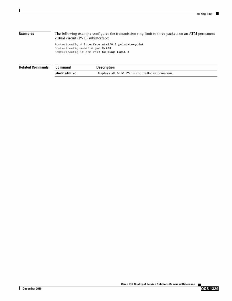
tx-ring-limit
QOS-1329Cisco IOS Quality of Service Solutions Command Reference
December 2010
Examples The following example configures the transmission ring limit to three packets on an ATM permanent virtual circuit (PVC) subinterface:
Router(config)# interface atm1/0.1 point-to-pointRouter(config-subif)# pvc 2/200Router(config-if-atm-vc)# tx-ring-limit 3
Related Commands Command Description
show atm vc Displays all ATM PVCs and traffic information.

vbr-nrt
QOS-1330Cisco IOS Quality of Service Solutions Command Reference
December 2010
vbr-nrtTo configure the variable bit rate-nonreal time (VBR-NRT) quality of service (QoS) and specify output peak cell rate (PCR), output sustainable cell rate (SCR), and output maximum burst cell size for an ATM permanent virtual circuit (PVC), PVC range, switched virtual circuit (SVC), VC class, or VC bundle member, use the vbr-nrt command in the appropriate command mode. To remove the VBR-NRT parameters, use the no form of this command.
vbr-nrt output-pcr output-scr output-maxburstsize [input-pcr] [input-scr] [input-maxburstsize]
no vbr-nrt output-pcr output-scr output-maxburstsize [input-pcr] [input-scr] [input-maxburstsize]
Cisco 10000 Series Router
vbr-nrt output-pcr output-scr output-maxburstsize
no vbr-nrt output-pcr output-scr output-maxburstsize
Syntax Description
Command Default Unspecified bit rate (UBR) QoS at the maximum line rate of the physical interface is the default.
Command Modes ATM PVC-in-range configuration (for an individual PVC within a PVC range)ATM PVC range configuration (for an ATM PVC range) ATM PVP configurationBundle-vc configuration (for ATM VC bundle members)Interface-ATM-VC configuration (for an ATM PVC or SVC)VC-class configuration (for a VC class)
Command History
output-pcr The output PCR, in kilobytes per second (kbps).
output-scr The output SCR, in kbps.
output-maxburstsize The output maximum burst cell size, expressed in number of cells.
input-pcr (Optional for SVCs only) The input PCR, in kbps.
input-scr (Optional for SVCs only) The input SCR, in kbps.
input-maxburstsize (Optional for SVCs only) The input maximum burst cell size, expressed in number of cells.
Release Modification
11.3T This command was introduced.
12.0(3)T This command was enhanced to support configuration of VBR-NRT QoS and specification of output PCR, output SCR, and output maximum burst cell size for ATM bundles and VC bundle members.
12.0(25)SX This command was integrated into Cisco IOS Release 12.0(25)SX and implemented on the Cisco 10000 series router.
12.1(5)T This command was made available in PVC range and PVC-in-range configuration modes.
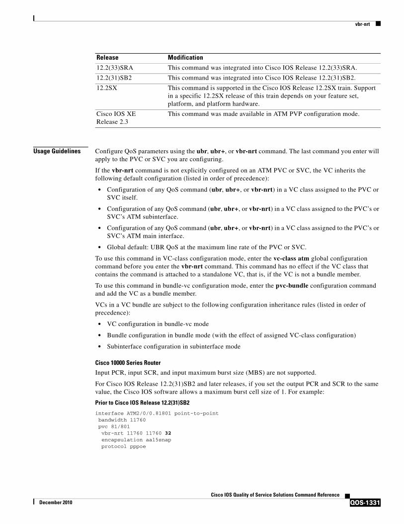
vbr-nrt
QOS-1331Cisco IOS Quality of Service Solutions Command Reference
December 2010
Usage Guidelines Configure QoS parameters using the ubr, ubr+, or vbr-nrt command. The last command you enter will apply to the PVC or SVC you are configuring.
If the vbr-nrt command is not explicitly configured on an ATM PVC or SVC, the VC inherits the following default configuration (listed in order of precedence):
• Configuration of any QoS command (ubr, ubr+, or vbr-nrt) in a VC class assigned to the PVC or SVC itself.
• Configuration of any QoS command (ubr, ubr+, or vbr-nrt) in a VC class assigned to the PVC’s or SVC’s ATM subinterface.
• Configuration of any QoS command (ubr, ubr+, or vbr-nrt) in a VC class assigned to the PVC’s or SVC’s ATM main interface.
• Global default: UBR QoS at the maximum line rate of the PVC or SVC.
To use this command in VC-class configuration mode, enter the vc-class atm global configuration command before you enter the vbr-nrt command. This command has no effect if the VC class that contains the command is attached to a standalone VC, that is, if the VC is not a bundle member.
To use this command in bundle-vc configuration mode, enter the pvc-bundle configuration command and add the VC as a bundle member.
VCs in a VC bundle are subject to the following configuration inheritance rules (listed in order of precedence):
• VC configuration in bundle-vc mode
• Bundle configuration in bundle mode (with the effect of assigned VC-class configuration)
• Subinterface configuration in subinterface mode
Cisco 10000 Series Router
Input PCR, input SCR, and input maximum burst size (MBS) are not supported.
For Cisco IOS Release 12.2(31)SB2 and later releases, if you set the output PCR and SCR to the same value, the Cisco IOS software allows a maximum burst cell size of 1. For example:
Prior to Cisco IOS Release 12.2(31)SB2
interface ATM2/0/0.81801 point-to-point bandwidth 11760 pvc 81/801 vbr-nrt 11760 11760 32 encapsulation aal5snap protocol pppoe
12.2(33)SRA This command was integrated into Cisco IOS Release 12.2(33)SRA.
12.2(31)SB2 This command was integrated into Cisco IOS Release 12.2(31)SB2.
12.2SX This command is supported in the Cisco IOS Release 12.2SX train. Support in a specific 12.2SX release of this train depends on your feature set, platform, and platform hardware.
Cisco IOS XE Release 2.3
This command was made available in ATM PVP configuration mode.
Release Modification

vbr-nrt
QOS-1332Cisco IOS Quality of Service Solutions Command Reference
December 2010
Cisco IOS Release 12.2(31)SB2 and Later Releases
interface ATM2/0/0.81801 point-to-point bandwidth 11760 pvc 81/801 vbr-nrt 11760 11760 1 encapsulation aal5snap protocol pppoe
Examples The following example specifies the output PCR for an ATM PVC to be 100,000 kbps, the output SCR to be 50,000 kbps, and the output MBS to be 64:
pvc 1/32vbr-nrt 100000 50000 64
The following example specifies the VBR-NRT output and input parameters for an ATM SVC:
svc atm-svc1 nsap 47.0091.81.000000.0040.0B0A.2501.ABC1.3333.3333.05vbr-nrt 10000 5000 32 20000 10000 64
Related Commands Command Description
abr Selects ABR QoS and configures output peak cell rate and output minimum guaranteed cell rate for an ATM PVC or virtual circuit class.
broadcast Configures broadcast packet duplication and transmission for an ATM VC class, PVC, SVC, or VC bundle.
bump Configures the bumping rules for a virtual circuit class that can be assigned to a virtual circuit bundle.
bundle Creates a bundle or modifies an existing bundle to enter bundle configuration mode.
class-int Assigns a VC class to an ATM main interface or subinterface.
class-vc Assigns a VC class to an ATM PVC, SVC, or VC bundle member.
encapsulation Sets the encapsulation method used by the interface.
inarp Configures the Inverse ARP time period for an ATM PVC, VC class, or VC bundle.
oam-bundle Enables end-to-end F5 OAM loopback cell generation and OAM management for a virtual circuit class that can be applied to a virtual circuit bundle.
oam retry Configures parameters related to OAM management for an ATM PVC, SVC, VC class, or VC bundle.
precedence Configures precedence levels for a virtual circuit class that can be assigned to a virtual circuit bundle and thus applied to all virtual circuit members of that bundle.
protect Configures a virtual circuit class with protected group or protected virtual circuit status for application to a virtual circuit bundle member.
protocol (ATM) Configures a static map for an ATM PVC, SVC, VC class, or VC bundle, and enables Inverse ARP or Inverse ARP broadcasts on an ATM PVC by either configuring Inverse ARP directly on the PVC, on the VC bundle, or in a VC class (applies to IP and IPX protocols only).
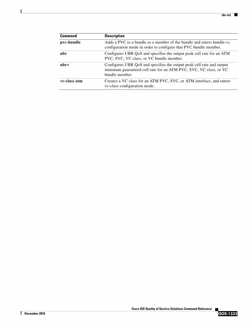
vbr-nrt
QOS-1333Cisco IOS Quality of Service Solutions Command Reference
December 2010
pvc-bundle Adds a PVC to a bundle as a member of the bundle and enters bundle-vc configuration mode in order to configure that PVC bundle member.
ubr Configures UBR QoS and specifies the output peak cell rate for an ATM PVC, SVC, VC class, or VC bundle member.
ubr+ Configures UBR QoS and specifies the output peak cell rate and output minimum guaranteed cell rate for an ATM PVC, SVC, VC class, or VC bundle member.
vc-class atm Creates a VC class for an ATM PVC, SVC, or ATM interface, and enters vc-class configuration mode.
Command Description

vc-hold-queue
QOS-1334Cisco IOS Quality of Service Solutions Command Reference
December 2010
vc-hold-queueTo configure the per-virtual circuit (VC) hold queue on an ATM adapter, use the vc-hold-queue command in interface configuration mode. To return to the default value of the per-VC hold queue, use the no form of this command.
vc-hold-queue number-of-packets
no vc-hold-queue number-of-packets
Syntax Description
Command Default The default value of the hold queue is set by the queueing mechanism in use.
Command Modes Interface configuration
Command History
Usage Guidelines This command can only be used on Cisco 7200 series routers and on Cisco 2600 and 3600 adapters that support per-VC queueing.
This command is configurable at the VC level only.
Examples The following example sets the per-VC hold queue to 55:
interface atm2/0.1pvc 1/101vc-hold-queue 55
Related Commands
number-of-packets Specifies number of packets that can be configured for the per-VC hold queue. Number of packets can be a minimum of 5 to a maximum of 1024.
Release Modification
12.1(5)T This command was introduced.
12.2(33)SRA This command was integrated into Cisco IOS Release 12.2(33)SRA.
12.2SX This command is supported in the Cisco IOS Release 12.2SX train. Support in a specific 12.2SX release of this train depends on your feature set, platform, and platform hardware.
Command Description
hold-queue Specifies the hold-queue limit of an interface.
show interfaces Displays statistics for all interfaces configured on the router or access server.
show queueing interface
Displays the queueing statistics of an interface or VC.

wrr-queue bandwidth
QOS-1335Cisco IOS Quality of Service Solutions Command Reference
December 2010
wrr-queue bandwidthTo allocate the bandwidth between the standard transmit queues, use the wrr-queue bandwidth command in interface configuration mode. To return to the default settings, use the no form of this command.
wrr-queue bandwidth weight-1 ... weight-n
no wrr-queue bandwidth
Syntax Description
Defaults The defaults are as follows:
• QoS enabled—4:255
• QoS disabled—255:1
Command Modes Interface configuration
Command History
Usage Guidelines You can configure up to seven queue weights on Cisco 7600 series routers that are configured with a Supervisor Engine 720.
You can configure up to three queue weights on Cisco 7600 series routers that are configured with a Supervisor Engine 2.
WRR allows bandwidth sharing at the egress port. This command defines the bandwidths for egress WRR through scheduling weights. Four queues participate in the WRR unless you enable the egress-expedite queue. The expedite queue is a strict-priority queue that is used until it is empty before using one of the WRR queues.
There is no order of dependencies for the wrr-queue bandwidth command. If you enable the egress priority, the weight ratio is calculated with the first two and the last parameters; otherwise, all four parameters are used.
The WRR weights are used to partition the bandwidth between the queues if all queues are nonempty. For example, entering weights of 1:3 means that one queue gets 25 percent of the bandwidth and the other queue gets 75 percent as long as both queues have data.
weight-1 ... weight-n WRR weights; valid values are from 1 to 255.
Release Modification
12.2(14)SX Support for this command was introduced on the Supervisor Engine 720.
12.2(17a)SX This command was changed to support seven queue weights.
12.2(17d)SXB Support for this command on the Supervisor Engine 2 was extended to Release 12.2(17d)SXB.
12.2(33)SRA This command was integrated into Cisco IOS Release 12.2(33)SRA.

wrr-queue bandwidth
QOS-1336Cisco IOS Quality of Service Solutions Command Reference
December 2010
Examples This example shows how to allocate a three-to-one bandwidth ratio:
Router(config-if)# wrr-queue bandwidth 3 1
Related Commands Command Description
show queueing interface
Displays queueing information.
wrr-queue queue-limit Sets the transmit-queue size ratio on an interface.
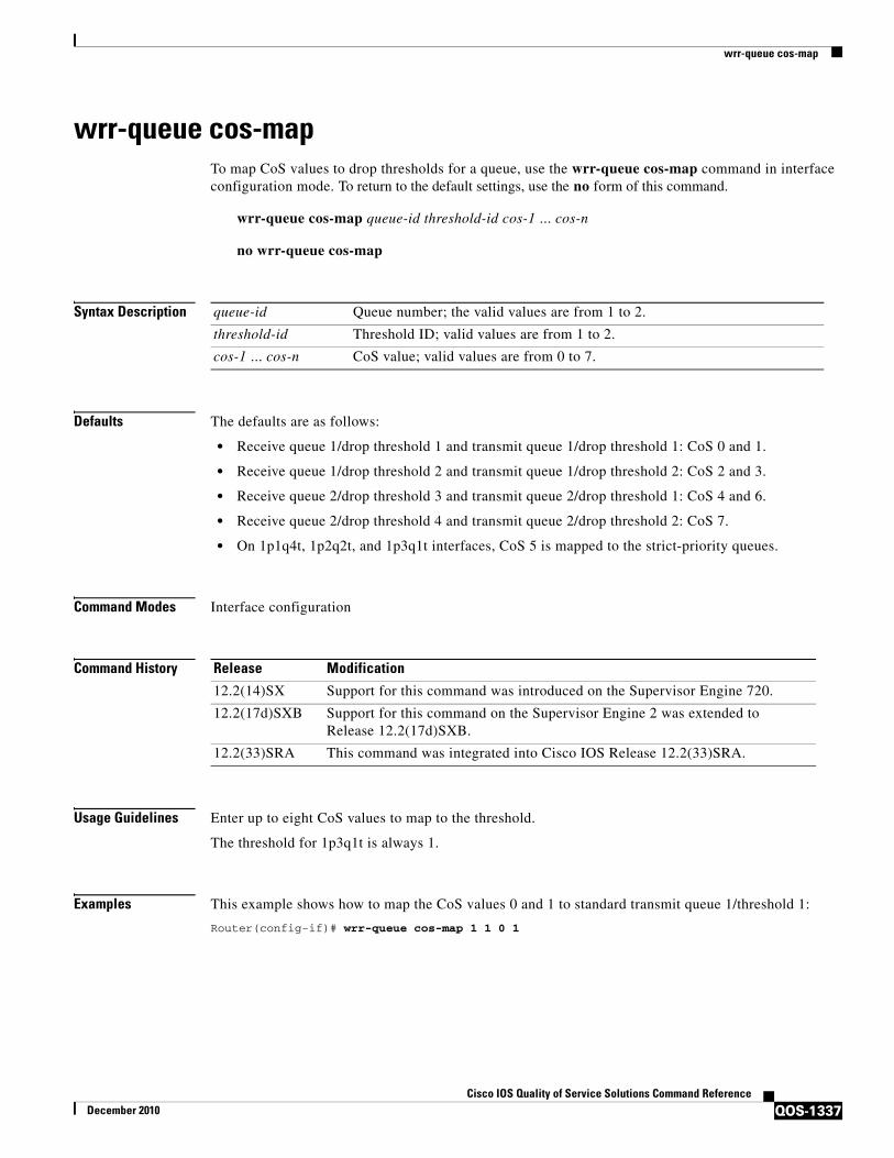
wrr-queue cos-map
QOS-1337Cisco IOS Quality of Service Solutions Command Reference
December 2010
wrr-queue cos-mapTo map CoS values to drop thresholds for a queue, use the wrr-queue cos-map command in interface configuration mode. To return to the default settings, use the no form of this command.
wrr-queue cos-map queue-id threshold-id cos-1 ... cos-n
no wrr-queue cos-map
Syntax Description
Defaults The defaults are as follows:
• Receive queue 1/drop threshold 1 and transmit queue 1/drop threshold 1: CoS 0 and 1.
• Receive queue 1/drop threshold 2 and transmit queue 1/drop threshold 2: CoS 2 and 3.
• Receive queue 2/drop threshold 3 and transmit queue 2/drop threshold 1: CoS 4 and 6.
• Receive queue 2/drop threshold 4 and transmit queue 2/drop threshold 2: CoS 7.
• On 1p1q4t, 1p2q2t, and 1p3q1t interfaces, CoS 5 is mapped to the strict-priority queues.
Command Modes Interface configuration
Command History
Usage Guidelines Enter up to eight CoS values to map to the threshold.
The threshold for 1p3q1t is always 1.
Examples This example shows how to map the CoS values 0 and 1 to standard transmit queue 1/threshold 1:
Router(config-if)# wrr-queue cos-map 1 1 0 1
queue-id Queue number; the valid values are from 1 to 2.
threshold-id Threshold ID; valid values are from 1 to 2.
cos-1 ... cos-n CoS value; valid values are from 0 to 7.
Release Modification
12.2(14)SX Support for this command was introduced on the Supervisor Engine 720.
12.2(17d)SXB Support for this command on the Supervisor Engine 2 was extended to Release 12.2(17d)SXB.
12.2(33)SRA This command was integrated into Cisco IOS Release 12.2(33)SRA.

wrr-queue dscp-map
QOS-1338Cisco IOS Quality of Service Solutions Command Reference
December 2010
wrr-queue dscp-mapTo map the hardware Differentiated Services Code Point (DSCP) values to the drop threshold values for a queue, use the wrr-queue dscp-map command in interface configuration mode. To return to the default settings, use the no form of this command.
wrr-queue dscp-map queue-id threshold-id dscp-1 ... dscp-n
no wrr-queue dscp-map queue-id
Syntax Description
Defaults The interface is in Class of Service (CoS) mode.
Command Modes Interface configuration
Command History
Usage Guidelines
Note To enter the wrr-queue dscp-map command, the interface must be in DSCP-queuing mode. Use the mls qos queue-mode mode-dscp command to set the mode to DSCP.
This command is supported on 10-Gigabit Ethernet ports only.
When mapping DSCP values, follow these guidelines:
• You can enter up to eight DSCP values that map to a queue and threshold.
• You can enter multiple commands to map additional DSCP values to the queue and threshold.
• You must enter a separate command for each queue and threshold.
Examples This example shows how to map the hardware DSCP values to the drop threshold values for a queue:
wrr-queue dscp-map 8 1 0 1 2 3
Related Commands
queue-id Queue number; valid values are from 1 to 8.
threshold-id Threshold ID; valid values are from 1 to 4.
dscp-1 ... dscp-n DSCP value; valid values are from 0 to 7.
Release Modification
12.2(18)SXF5 This command was introduced.
show queueing interface Displays queueing information.
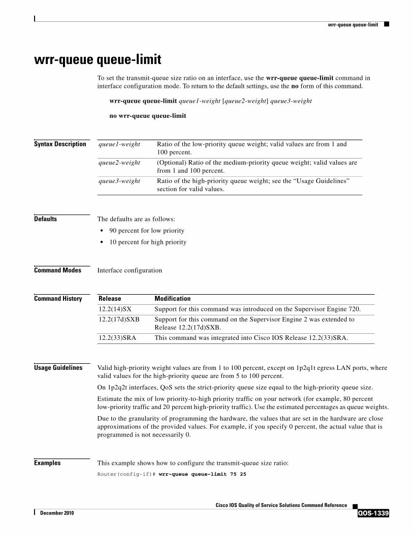
wrr-queue queue-limit
QOS-1339Cisco IOS Quality of Service Solutions Command Reference
December 2010
wrr-queue queue-limitTo set the transmit-queue size ratio on an interface, use the wrr-queue queue-limit command in interface configuration mode. To return to the default settings, use the no form of this command.
wrr-queue queue-limit queue1-weight [queue2-weight] queue3-weight
no wrr-queue queue-limit
Syntax Description
Defaults The defaults are as follows:
• 90 percent for low priority
• 10 percent for high priority
Command Modes Interface configuration
Command History
Usage Guidelines Valid high-priority weight values are from 1 to 100 percent, except on 1p2q1t egress LAN ports, where valid values for the high-priority queue are from 5 to 100 percent.
On 1p2q2t interfaces, QoS sets the strict-priority queue size equal to the high-priority queue size.
Estimate the mix of low priority-to-high priority traffic on your network (for example, 80 percent low-priority traffic and 20 percent high-priority traffic). Use the estimated percentages as queue weights.
Due to the granularity of programming the hardware, the values that are set in the hardware are close approximations of the provided values. For example, if you specify 0 percent, the actual value that is programmed is not necessarily 0.
Examples This example shows how to configure the transmit-queue size ratio:
Router(config-if)# wrr-queue queue-limit 75 25
queue1-weight Ratio of the low-priority queue weight; valid values are from 1 and 100 percent.
queue2-weight (Optional) Ratio of the medium-priority queue weight; valid values are from 1 and 100 percent.
queue3-weight Ratio of the high-priority queue weight; see the “Usage Guidelines” section for valid values.
Release Modification
12.2(14)SX Support for this command was introduced on the Supervisor Engine 720.
12.2(17d)SXB Support for this command on the Supervisor Engine 2 was extended to Release 12.2(17d)SXB.
12.2(33)SRA This command was integrated into Cisco IOS Release 12.2(33)SRA.

wrr-queue queue-limit
QOS-1340Cisco IOS Quality of Service Solutions Command Reference
December 2010
Related Commands Command Description
show queueing interface
Displays queueing information.
wrr-queue bandwidth Allocates the bandwidth between the standard transmit queues.

wrr-queue random-detect
QOS-1341Cisco IOS Quality of Service Solutions Command Reference
December 2010
wrr-queue random-detect To enable WRED or specify the minimum and maximum WRED threshold for the specified queues on 1p2q2t and 1p3q1t interfaces, use the wrr-queue random-detect command in interface configuration mode. To return to the default settings, use the no form of this command.
wrr-queue random-detect queue-id
wrr-queue random-detect {max-threshold | min-threshold} queue-id threshold-percent-1 ... threshold-percent-n
no wrr-queue random-detect queue-id
no wrr-queue random-detect {max-threshold | min-threshold} queue-id
Syntax Description
Defaults The default is that WRED is disabled. When WRED is enabled, the defaults are as follows:
• The maximum threshold is (low) 40 percent and (high) 100 percent.
• The minimum thresholds are both set to zero.
Command Modes Interface configuration
Command History
Usage Guidelines 1p2q1t and 1p3q1t interfaces have WRED-drop thresholds in their standard transmit queues. You can configure 1p3q1t transmit queues to use a WRED-drop threshold or a tail-drop threshold.
To enable WRED-drop thresholds on 1p2p1t interfaces, enter the wrr-queue random-detect queue-id command. Use the no form of this command to disable WRED.
To enable WRED-drop thresholds on 1p3q1t interfaces, enter the wrr-queue random-detect queue-id command. To return to the tail-drop threshold, enter the no wrr-queue random-detect queue-id command.
queue-id Queue number; valid values are 1, 2, or 3.
max-threshold Specifies the maximum WRED-drop threshold.
min-threshold Specifies the minimum WRED-drop threshold.
threshold-percent-1threshold-percent-n
Threshold weights; valid values are from 1 to 100 percent.
Release Modification
12.2(14)SX Support for this command was introduced on the Supervisor Engine 720.
12.2(17d)SXB Support for this command on the Supervisor Engine 2 was extended to Release 12.2(17d)SXB.
12.2(33)SRA This command was integrated into Cisco IOS Release 12.2(33)SRA.

wrr-queue random-detect
QOS-1342Cisco IOS Quality of Service Solutions Command Reference
December 2010
The queue-id argument is 1 for the standard low-priority queue, 2 for the standard high-priority queue, and 3 for strict priority.
The threshold in the strict-priority queue is not configurable.
Each queue on a 1p2q2t interface has two thresholds; 1p3q1t interfaces have one threshold.
Each threshold has a low and a high WRED value.
WRED values are a percentage of the queue capacity.
For additional information on configuring WRED thresholds, refer to the QoS chapter in the Cisco 7600 Series Router Cisco IOS Software Configuration Guide.
Examples This example shows how to configure the low-priority transmit-queue high-WRED drop thresholds:
Router(config-if)# wrr-queue random-detect max-threshold 1 60 100
Related Commands Command Description
show queueing interface
Displays queueing information.
wrr-queue queue-limit Sets the transmit-queue size ratio on an interface.

wrr-queue threshold
QOS-1343Cisco IOS Quality of Service Solutions Command Reference
December 2010
wrr-queue thresholdTo configure the drop-threshold percentages for the standard receive and transmit queues on 1q4t and 2q2t interfaces, use the wrr-queue threshold command in interface configuration mode. To return to the default settings, use the no form of this command.
wrr-queue threshold queue-id threshold-percent-1 ... threshold-percent-n
no wrr-queue threshold queue-id
Syntax Description
Defaults When you enable QoS, the default values are as follows:
• 100 percent for threshold 1
• 60 percent for threshold 2
Command Modes Interface configuration
Command History
Usage Guidelines Use the transmit queue and threshold numbers.
The queue-id argument is 1 for the standard low-priority queue and 2 for the standard high-priority queue.
Always set threshold 2 to 100 percent.
Receive-queue drop thresholds are supported only on Gigabit Ethernet interfaces that are configured to trust CoS.
Examples This example shows how to configure receive queue 1/threshold 1 and transmit queue 1/threshold 1:
Router(config-if)# wrr-queue threshold 1 60 100
queue-id Queue number; valid values are 1 and 2.
threshold-percent-1threshold-percent-n
Number of weights for queues 1 and 2; valid values are from 1 to 100 percent.
Release Modification
12.2(14)SX Support for this command was introduced on the Supervisor Engine 720.
12.2(17d)SXB Support for this command on the Supervisor Engine 2 was extended to Release 12.2(17d)SXB.
12.2(33)SRA This command was integrated into Cisco IOS Release 12.2(33)SRA.
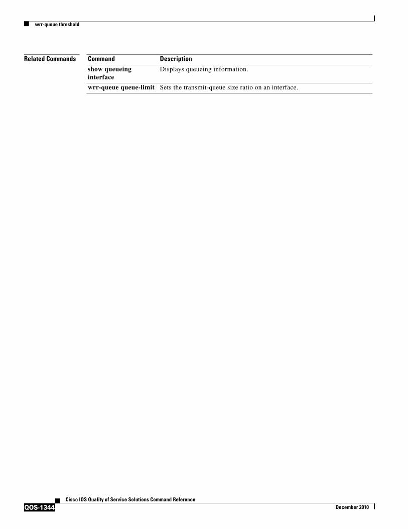
wrr-queue threshold
QOS-1344Cisco IOS Quality of Service Solutions Command Reference
December 2010
Related Commands Command Description
show queueing interface
Displays queueing information.
wrr-queue queue-limit Sets the transmit-queue size ratio on an interface.