shower control installation operation &b -...
TRANSCRIPT

Maintenance Guide
Operation &B
Installation
SHOWER CONTROL
THESE INSTRUCTIONS ARE TO BE LEFT WITH THE USER

2
ContentsSection Page
1 ..... Introduction ................................................................... 3
2 ..... Important Safety Information ........................................... 4
3 ..... Pack Contents Checklist ................................................... 5
4 ..... Dimensions ........................................................................ 8
5 ..... Specifications .................................................................... 9
6 ..... Installation Requirements ............................................... 10
7 ..... Pressure Setting .............................................................. 16
8 ..... Installation
Select
Exposed Supplies ......................................................... 18
Back Inlet Supplies ....................................................... 21
Select B
Solid and Dry-lined Walls .............................................. 23
Shower Cubicle or Laminated Panel Walls .................... 30
9 ..... Reversed Inlet Connections ........................................... 33
10 ... Commissioning ............................................................... 35
11 ... Operation ......................................................................... 37
12 ... Fault Diagnosis ............................................................... 38
13 ... Maintenance .................................................................... 42
14 ... Accessories ..................................................................... 43
15 ... Spare Parts ...................................................................... 44
Guarantee, Customer Care Policy, and How to contact us
.............................................................................. Back cover
3
Introduction
If you experience any difficulty with the installation or operation of your newshower control, then please refer to Fault Diagnosis, before contactingKohler Mira Limited. Our telephone and fax numbers can be found on the back coverof this guide.
Thank you for purchasing a quality Mira product. To enjoy the full potential of your newproduct, please take time to read this guide thoroughly, having done so, keep it handyfor future reference.
The Mira Select is a thermostatic shower control with independent selection of sprayforce and temperature. The shower control incorporates a wax capsule temperaturesensing unit. This provides an almost immediate response to changes in pressuresor temperature of the incoming water supplies to maintain the selected temperature.An adjustable maximum temperature stop is provided which limits the temperature tothe desired level. The flow control mechanism utilizes ceramic plate technologyoperating directly on the hot and cold inlets to provide complete isolation of theincoming water supplies. An adjustable pressure setting allows the Select to be usedin either high or low pressure applications.
Shower controls covered by this guide:
Mira Select
An exposed shower control for connection to exposed or rear entry pipework.Available in white/chrome or all chrome finish.
Mira Select B
A built-in shower control for connection to concealed pipework. A right angledconnector is supplied to allow exposed shower fittings, such as the Select UV fittings,to be used with the Select B. Available in white, white/chrome or all chrome finish.
SectionSection
1
4
Important Safety Information
Warning!
1. Products manufactured by us are safe and without risk provided they areinstalled, used and maintained in good working order in accordance with ourinstructions and recommendations.
Caution!
1. Read all of these instructions.
2. Retain this guide for later use.
3. Pass on this guide in the event of change of ownership of the installation site.
4. Follow all warnings, cautions and instructions contained in this guide.
5. The plumbing installation must comply with the requirements of UK WaterRegulations/Bye-laws (Scotland), Building Regulations or any particularregulations and practices, specified by the local water company or waterundertakers. The installation should be carried out by a plumber or contractorwho is registered, or is a member of, an association such as:
Institute of Plumbing (IOP), throughout the UK, Tel: 01708 472791.
National Association of Plumbing, Heating and Mechanical ServicesContractors (NAPH & MSC), England and Wales, Tel: 01203 470626.
Scottish and Northern Ireland Plumbing Employers’ Federation (SNIPEF),Scotland and Northern Ireland, Tel: 0131 225 2255.
6. Anyone who may have difficulty understanding or operating the controls of anyshower should be attended whilst showering. Particular consideration shouldbe given to the young, the elderly, the infirm, or anyone inexperienced in thecorrect operation of the controls.
SectionSection
2

5
Pack Contents Checklist Tick the appropriate boxes to familiarize yourself with the part names and to
confirm that the parts are included.
1. Select Shower Control
2 x Compression Nuts
2 x Pipe Concealing Plates
2 x Olives
1 x 2.5 mm A/FHexagon Wrench2 x Wall Plugs
1 x Select
2 x No. 8 x 1 3/4" Screw
1 x Installation Key
1 x 'O' Seal
2 x Gaskets
2 x Inlet Connectors
1 x Outlet Nipple
SectionSection
3

6
2. Select B Shower Control
3 x Compression Nuts
3 x Olives
1 x Foam Seal
1 x Support Bracket
1 x ConcealingPlate Assembly
1 x Select B
1 x Outlet Nipple
2 x M4 x 16 mm Screw
1 x 'O' Seal
2 x M4 x 30 mm Screw
2 x Wall Plugs
2 x No. 8 x 1 1/4" Screw
1 x Installation Key
1 x Flow Knob
1 x Temperature Knob
1 x 2.5 mm A/FHexagonWrench
1 x StraightPushfit Adaptor
2 x ElbowPushfit Adaptors

7
3. Documentation1 x Installation, Operation and Maintenance Guide
3 x No.6 x 1/2" Screw
1 x 1/2" BSP Nipple
1 x Foam Seal
1 x Wall Plate
1 x Mounting Bush
1 x Elbow
1 x Shroud

8
Dimensions
1. Select
2. Select B
Falling Supplies
Rising Supplies
Back Inlet
57 to 74 mm
35 mm
35 mm
56 mmDia.
163 mm Diameter
153 mm 95 mm
76 mmDia.
SectionSection
4
175 mm Diameter
120 mm 130 mm

9
Specifications
Pressure RangesThe Select/Select B has an adjustable pressure range to suit the particular installation.For methods of measuring the system pressure, refer to Installation Requirements.
Select & Select B - High Pressure Setting
1. Minimum maintained pressure: 1.0 bar (10 Metre head) when used with Mirashower fittings.
2. Maximum maintained pressure: 5.0 bar.
3. Maximum static pressure: 10 bar.
Select & Select B - Low Pressure Setting
4. Minimum maintained pressure: 0.1 bar (1 Metre head) when used with Mirashower fittings (0.06 bar without fittings).
5. Maximum maintained pressure 1.0 bar.
6. Maximum static pressure: 10 bar.
Note! Nominally equal inlet supply pressures are recommended for optimumperformance.
Temperature Control1. Close temperature control is provided between 30 and 50 °C.
Note! The temperature control specification, outlined below, is achieved with theblend set between 35 and 45 °C, with supply temperatures of 15 °C cold and 65°C hot, AND, nominally equal inlet supply pressures.
2. The blended temperature is maintained within 2 °C with a 10 °C change in the hotor cold supply.
3. The wax capsule sensor effects a shut down to seepage in approximately 2seconds if the cold supply fails. Shut down to seepage is only achieved if the hotsupply is 12 °C above the blend temperature.
Plumbing ConnectionsInlet15mm Compression or 1/2'' BSP male (Select).15mm Compression (Select B)*.
Outlet1/2'' BSP male (Select).15mm Compression or 1/2'' BSP male (Select B)*.
*Inlet and outlet adaptors are provided to allow the easy connection of 15mmpushfit fittings to the Select B.
SectionSection
5

10
Installation Requirements
General
Read the section Important Safety Information first.
1. Supply pipework MUST be flushed to clear debris before connecting the showercontrol. A flushing cartridge is available free of charge upon request (refer toAccessories).
2. Do not fit any form of flow control in the outlet pipework.
3. Do not install the product in a position where it could become frozen.
4. Layout and sizing of pipework MUST be such that nominally equal inlet supplypressures are achieved and effects of other draw-offs are minimised.
5. Conveniently situated isolating valves MUST be fitted for servicing purposes.
6. If the shower control is to be used with a multipoint water heater, combinationboiler, thermal store or unvented system an expansion vessel must be fitted toaccommodate the expansion of water in the domestic hot water supply (this mayalready be part of the system, check with the appliance manufacturer).
7. Do not use excessive force when making connections.
8. Do not install the shower control in a position that restricts service access.
SectionSection
6

11
1. Instantaneous gas-heated showers (e.g. combination boilers)
The shower MUST be installed with a multipoint gas water heater or combinationboiler of a fully modulating design (i.e. where the water draw-off rate indirectlycontrols the gas flow rate to the burner).A drop tight pressure reducing valve (PRV) MUST be fitted if the supply pressuresexceed 5 bar maintained.An expansion vessel MUST be fitted (and regularly maintained) if any form ofbackflow prevention device is fitted, e.g. non-return valve, PRV. This will ensure thatexcess expansion or pulse pressures do not damage the product or the plumbingsystem. The expansion vessel may already be fitted within the boiler (check with themanufacturer) and is in addition to the normally larger central heating expansionvessel.The layout and sizing of pipework MUST be such that nominally equal inlet supplypressures are achieved AND the effects of other draw-offs are minimized.The hot supply temperature MUST be at least 12 °C hotter than the required blendtemperature for optimum performance.
Float operated valve
Stop or servicing valve
Shower control
Warning or overflow pipe
Drop tight pressure reducing valve(PRV)
Typical Suitable Installations
Key to symbols
HOTCOLD
Twin impeller inlet pump
Single impeller outlet pump
Tempering valve
Mini expansion vessel
Non-return Valve

12
3. Mains pressurised instantaneous hot water shower, heated from a thermalstore
Packages of this type, fitted with a tempering valve can be used.A drop tight pressure reducing valve MUST be fitted if the supply pressures exceed5 bar maintained.An expansion vessel MUST be fitted (and regularly maintained) if any form ofbackflow prevention device is fitted, e.g. non-return valve, PRV. This will ensure thatexcess expansion or pulse pressures do not damage the product or the plumbingsystem. The expansion vessel may already be fitted externally or internally within thethermal store (check with thermal store manufacturer).The layout and sizing of pipework MUST be such that nominally equal inlet supplypressures are achieved AND the effects of other draw-offs are minimized.
COLD HOT
2. Gravity fed showers
The shower MUST be fed from a cold water storage cistern and hot water cylinderproviding nominally equal pressures.

13
Safety devicesnot shownfor clarity
HOTCOLD
4. Unvented mains pressure showers
The shower can be installed with an unvented, stored hot water cylinder. Only a"competent person" as defined by the Building Regulations may fit this type ofsystem.For packages with no cold water take off after the appliance reducing valve, it will benecessary to fit an additional drop tight pressure reducing valve when the mainspressure is over 5 bar. The drop tight pressure reducing valve must be set at the samevalue as the unvented package pressure reducing valve.
Note! An expansion vessel MUST be fitted (and regularly maintained) if any form ofbackflow prevention device is fitted, e.g. non-return valve, PRV. This will ensure thatexcess expansion or pulse pressures do not damage the product or the plumbingsystem.
The layout and sizing of pipework MUST be such that nominally equal inlet supplypressures are achieved AND the effects of other draw-offs are minimized.
Combined outlet PRVwith internal non-return valves- Expansion vessel required.
Cold take-off after PRV- Expansion pressure taken up by
unvented cylinder expansion vessel.
Reducedpressure tounventedcylinder
HighInlet
Pressure
Reducedpressure toshower coldinlet
Reducedpressure tounventedcylinder
HighInletPressure
Reducedpressure toshower coldinlet
ExpansionVessel

14
5. Pumped showers (inlet pumps)
The shower can be installed with an inlet pump (twin impeller). The pump MUSTbe located on the floor next to the hot water cylinder. The hot water cylinder/ventpipes must be arranged as shown to achieve air separation.The layout and sizing of pipework MUST be such that nominally equal inlet supplypressures are achieved AND the effects of other draw-offs are minimized.
6. Pumped showers (outlet pumps)
The built-in shower can be installed with an outlet pump (single impeller). Thepump MUST be located on the floor near to the shower control.The layout and sizing of pipework MUST be such that nominally equal inlet supplypressures are achieved AND the effects of other draw-offs are minimized.
90 °
30 to 60 °
90 °
30 to 60 °
Air Separation
Air Separation

15
Measuring System Pressures1. General
It is important that system pressures do not exceed the Specifications for Select.If the system pressure is not known then the system pressure MUST be measuredas explained in this section.Pressures are those present at the inlet to the appliance either whilst running(maintained) or in the off state (static). Nearby hot and cold taps connected to thesame proposed feed pipes as the appliance can be used to measure the staticpressure. No other fitting or appliance should be in use at this time.Water pressures vary throughout the day, therefore you must ensure that waterpressures do not drop below or exceed the minimum/maximum required (refer toSpecifications).
2. To measure static pressure (refer to Figure 1)With the pressure testing device firmly connected to a tap drawing from one of theproposed feed pipes and the outlet from the device in the off position, the tap isturned on and the static pressure noted.
3. To measure maintained pressure (refer to Figure 1)The pressure testing device is connected as above, the taps turned on and theoutlet from the device opened until a flow of around 5 l/min is obtained (this iseasily done by timing the flow into a calibrated container). The maintainedpressure which can be expected when the shower is in operation can then beread. This should be carried out on the hot and cold supply.
4. To measure pressure dropPressure drop results from another fitting being turned on when the shower is inuse. Having checked the maintained pressure (refer to paragraph 3.) and with thedevice still discharging at approximately 5 l/min, turn on a second draw-off fromthe same feed pipe. This new reading will show the pressure drop from 3. andshould be above the minimum maintained pressure recommended by themanufacturer.
e.g. Static pressure - 3 bar.Maintained pressure at approx. 5 l/min - 2.5 bar.When second draw-off operates the pressure drops to 1.5 bar.The pressure drop is above the minimum recommended (refer to Specifications).
Pressure Gauge
Hose TypeTap Connector
Ball Valve
Pressure Testing DeviceFigure 1

16
Pressure Setting
Important! Before the Select shower control can be installed the cartridge assemblyMUST be set to the correct pressure setting for the plumbing system.
General
Read the section Installation Requirements first.
The table below gives the correct pressure setting for typical plumbing installations.Refer to Installation Requirements : “Measuring System Pressures”, for measuringthe actual system pressures.
Note! For user comfort and convenience we recommend the low pressuresetting for pumps that provide maintained system pressures below 1 bar, andthe high pressure setting for pumps that provide maintained system pressuresabove 1 bar.
High Pressure Setting
Gravity-fed showers.
Instantaneous gas heatedshowers (fully modulatingtype).
Mains pressurisedinstantaneous hot watershower, heated from athermal store.
Unvented mains pressureshowers.
Pumped showers.
System Low Pressure Setting
SectionSection
7
Adjusting Select Pressure Setting
1. Use the 2.5 mm A/F hexagon wrench (supplied) to loosen the two grub screws.
2. Remove the backplate. This will allow access to the rear face of the cartridgeassembly.
3. Adjust the pressure setting if necessary (refer to "Use of Installation Key").

17
Adjusting Select B Pressure Setting
4. Remove the two screws that hold the building-in shroud to the backplate.
5. Remove the building-in shroud.
6. Refit the two screws temporarily into the backplate.
7. Use the 2.5 mm hexagonal wrench (supplied) to loosen the two grub screws.
8. Remove the shower control from the backplate. This will allow access to the rearface of the cartridge assembly.
9. Adjust the pressure setting if necessary (refer to "Use of Installation Key").
Use of Installation Key
An installation key is available to help you during installation of the Mira Select. The keyhas the following functions:
1. The plastic end prongs fit neatly into the pressure selector to enable you to easilychange the pressure setting to high or low pressure.
2. Refit the shower control to the backplate and use the 2.5 mm hexagonal wrenchto tighten the grub screws.
LowPressure
HighPressure
12 mm A/F Hexagonal Wrench.Used for Removal/Installation of theInlet and Outlet Nipples.
1.
Used for High/LowPressure Adjustment
2.

18
Select
Exposed Supplies (rising or falling surface pipework)
Important! Before the Select shower control can be installed the cartridge assemblyMUST be set to the correct pressure setting for the plumbing system. Refer to thesection Pressure Setting.
Note! The Select is supplied with inlet connections hot left, cold right and bottomoutlet as standard. For installations with reversed hot and cold supplies completethe installation and refer to the section Reversed Inlet Connections.
1. Before you decide on the final position of your shower control, please bear in mindthe following:
Decide on a suitable position for the shower control. The position of the showercontrol and the shower fittings must provide a minimum gap of 25 mm betweenthe spill-over level of the shower tray/bath and the handset. This is to preventbacksiphonage.
Determine whether the hot or cold water services will be connected to theshower control from the bottom (rising) or from top (falling).
2. Use the 2.5 mm A/F hexagon wrench (supplied) to loosen the two grub screwsthat secure the backplate to the shower control.
3. Remove the backplate.
4. Mark the final position on the finished wall surface using the backplate as atemplate. Make sure that the two holes on the backplate are vertically aligned.
5. For solid walls drill the backplate holes with a 6 mm diameter drill and insert thewall plugs (supplied). For other types of wall structure alternative fixings may berequired.
6. Fix the backplate to the wall with the two No. 8 x 1 3/4" screws (supplied).
7. Install the hot and cold supply pipes at 153 mm centres.
8. Adjust the inlet elbow to accept falling or rising supplies as follows:
Using the 2.5 mm A/F hexagonal wrench loosen the grub screws and remove theinlet elbows.
Ensure that the 'O' seal locates correctly on the inlet connector.
Turn the inlet elbows to the required position and refit onto the inlet connectors.
Tighten the grub screws to fix the inlet elbows.
InstallationSectionSection
8

19
9. Fit the gaskets to the short inlet nipples and screw the nipples with tapered endsoutermost to accept the compression fittings.
10. Tighten the nipples fully with a 12 mm A/F hexagonal wrench (not supplied) orkey.
11. Thoroughly flush the hot and cold water supply pipes. The supplies mustbe clean and free from debris before connecting the shower control. Failureto do so may result in product malfunction.
Alternatively fit the shower control as instructed, remove the cartridge anduse the Flushing Cartridge (refer to Accessories).
12. Locate the shower control onto the backplate and secure with the grub screws.
13. Slip the compression nuts and olives over the supply pipes and then make theconnection to the inlet pipework. Make sure that you protect the plated surfaces.
14. Turn on the water supplies and check for any leaks.
Shower fittings
15. Install the shower fittings. Refer to the Installation, Operation and MaintenanceGuide for the shower fittings.

20
Exposed Supplies (rising or falling pipework)Figure 1
Backplate
2.5 mm A/FHexagonal Wrench
Wall Plugs
Fixing Screws
Grub Screw
Inlet Elbow 'O' Seal
Grub Screw
Compression Nut
RisingSupply
FallingSupply
Supply Pipe
Olive
Inlet Nipple
Gasket

21
1. Before you decide on the final position of your shower control, please bear in mindthe following:
Decide on a suitable position for the shower control. The position of the showercontrol and the shower fittings must provide a minimum gap of 25 mm betweenthe spill-over level of the shower tray/bath and the handset. This is to preventbacksiphonage.
2. Use a spirit level and a pencil to mark the route for the hot and cold water supplypipes at 153 mm centres.
3. Remove the plaster and brick/block to the required depth to conceal the pipework.
4. Install the supply pipes. The pipes must project from the finished wall by 13 mmFinish the surface of the wall as required. The recesses made in the wall for theconcealing plates must be 32 mm diameter x 10 mm deep. Ensure the pipeworkelbows are set sufficiently into the wall to avoid fouling the concealing plates.
5. Follow the shower control installation procedure as for "Exposed Supplies":instructions 2. to 6.
6. Fit the gaskets to the short inlet nipples and screw the nipples with the taperedends outermost to accept the compression fittings.
Tighten the nipples fully with a 12 mm A/F hexagonal wrench (not supplied).
7. Fit the concealing plates over the pipework into the enlarged recesses in thefinished wall surface.
8. Thoroughly flush the hot and cold water supply pipes. The supplies mustbe clean and free from debris before connecting the shower control. Failureto do so may result in product malfunction.
Alternatively fit the shower control as instructed, remove the cartridge anduse the Flushing Cartridge (refer to Accessories).
9. Slip the compression nuts and olives over the supply pipes.
Locate the shower control body onto the backplate and secure by tightening thegrub screw using the 2.5 mm A/F hexagonal wrench (supplied).
Back Inlet Supplies (rising or falling concealed pipework)
Important! Before the Select shower control can be installed the cartridge assemblyMUST be set to the correct pressure setting for the plumbing system. Refer to thesection Pressure Setting.
Note! The Select is supplied with inlet connections hot left, cold right and bottomoutlet as standard. For installations with reversed hot and cold supplies completethe installation and refer to the section Reversed Inlet Connections.

22
2.5 mm A/FHexagonal Wrench
Make the connections to the inlet pipework. Make sure that you protect thechrome plated surfaces whilst you tighten the compression nuts.
10. Turn on the water supplies and check for any leaks.
Shower fittings
11. Install the shower fittings. Refer to the Installation, Operation and MaintenanceGuide for the shower fittings.
Back Inlet Supplies (rising or falling concealed pipework)Figure 2
Wall Plugs
FixingScrews
Grub Screw
Inlet Elbow
'O' Seal
GrubScrew
153 mm
13 mm
Concealing Plate
Olive
Inlet Nipple
Gasket
Compression Nut
Backplate
1/2" maleBSP
15mmCompression
Ensure thepipework elbowsare set sufficientlyinto the wall toavoid fouling theconcealing plates.

23
Select B
Solid and Dry-lined Walls
Important! Before the Select shower control can be installed the cartridge assemblyMUST be set to the correct pressure setting for the plumbing system. Refer to thesection Pressure Setting.
The built-in shower control is supplied with a support bracket that can be used to installthe shower control into a solid or dry-lined wall structure. Installers may wish toconsider other options such as fabricating rear supports using wooden noggins,however, these methods of fixing are beyond the scope of this guide.
The building-in depth for the support bracket is 58 mm.
The building-in depth for the shower control (to the finished wall surface) is between64 and 81 mm. The building-in depth calculation must include the final thickness ofplaster and tiles. This dimension determines how much of the flow and temperaturecontrol knob will be visible through the concealing plate when the installation iscomplete.
A building-in shroud is supplied, which protects the shower control during plasteringand provides a reference for the building-in depth when chasing out the wall surface.
The built-in shower control has 1/2" BSP male inlets and is supplied with 15 mmcompression fittings. The outlet has a 1/2" BSP tapping and is supplied with a specialscrew in nipple terminating in a 1/2" BSP male or 15 mm compression fitting. If pushfitconnections are used within the installation the special pushfit adaptors supplied canbe fitted to the shower, to allow easier connection.
Both built-in and exposed shower fittings can be used with the Select B. If exposedshower fittings are used the right angled connector (RAC) will require fitting.
Installation of Built-in and Exposed Shower FittingsFigure 3
RAC supplied withshower control
OutletPipe
Select UVexposed shower
fittings
OutletPipe
Select BIR Built-in Spray Head

24
1. Decide on a suitable position for the shower control. The position of the showercontrol and the shower fittings must provide a minimum gap of 25 mm betweenthe spill-over level of the shower tray/bath and the handset. This is to preventbacksiphonage.
2. Determine whether the hot or cold water services will be connected to the showercontrol from the top (falling) or from the bottom (rising).
3. Remove the plastic building-in shroud. The two M5 x 50 mm retaining screwsshould be screwed temporarily into the base of the shower control for use later.
Familiarise yourself with the hot and cold water inlet ports and the outlet port. TheSelect B is supplied with inlet connections hot left, cold right and top outlet asstandard. For installations with reversed hot and cold supplies complete theinstallation and refer to the section Reversed Inlet Connections.
4. Determine the route for the outlet pipework. It is recommended that, if the rightangled connector (RAC) is to be fitted, the outlet be positioned above and to oneside of the shower control. This is to prevent the flexible hose from obstructingthe temperature and flow knobs of the shower control.
5. Mark an opening sufficient to accommodate the shower control approximately245 mm x 125 mm on the surface of the wall. Alternatively, mark a 150 mmdiameter hole for a carbide tipped hole cutter.
6. Mark the route of the supply and outlet pipes. Using the building-in shroud as aguide remove the plaster and brickwork/dry-lining to the required depth.
Note! The depth of concealment must be such that the final wall surface (e.g.plaster and tiles) finishes on the raised portion of the plastic building-in shroud.
7. Mark the support bracket fixing hole positions. The support bracket must befixed at 45°. Drill a 6.0 mm diameter hole at each of the marked positions andinsert the wall plugs (supplied).
8. Install the hot and cold supply pipes.
9. Make sure that the 'O' seal and the foam seal are correctly located on the outletnipple.
10. Screw the outlet nipple into the shower control, flat face end first. Make sure thatthe shoulder on the outlet nipple engages with the recess in the backplate.Tighten the outlet nipple with a 12 mm A/F hexagon wrench (not supplied).
If the installation uses pushfit fittings fit the adaptors supplied with the shower control.Follow the "Fitting Inlet and Outlet Pushfit Adaptors" installation instructions in thesection Select B: "Solid and dry-lined walls".

25
11. Fix the shower control to the support bracket using the two M4 x 16 mm screws(supplied).
12. Align the holes in the support bracket with the holes in the wall and secure theshower control with the two No. 8 x 1 1/4" screws (supplied).
13. Thoroughly flush the hot and cold water supply pipes. The supplies mustbe clean and free from debris before connecting the shower control. Failureto do so may result in product malfunction.
Alternatively fit the shower control as instructed, remove the cartridge anduse the Flushing Cartridge (refer to Accessories).
14. Slide the compression nuts and olives over the supply pipes.
15. Insert the hot and cold supply pipes fully into the shower control and slide theolives and compression nuts into place.
16. Use a suitable spanner to tighten the compression nuts.
17. Install the outlet pipe.
18. Slide the compression nut and olive over the outlet pipe.
19. Insert the outlet pipe fully into the shower control and slide the olive andcompression nut into place.
20. Use a suitable spanner to tighten the compression nut.
21. Turn on the water supplies and check for any leaks.
22. Refit the building-in shroud removed during pressure setting. Secure the shroudin position with the two M5 x 50 mm screws.
23. Plaster and tile as necessary up to the sides of the building-in shroud. Thefinished surface of the wall must be between the minimum and maximum depthson the building-in shroud.
24. When the plaster/tiles have set remove the building-in shroud. Retain the twoM5 x 50 mm screws for use later.
25. Fit the foam seal to the back of the mounting bracket.
26. Fix the mounting bracket to the shower control with the two M5 x50 mm screws.
27. Push the concealing plate firmly on to the mounting bracket until it clips intoposition.
28. To complete the installation refer to the "Shower Fittings" section inSelect B: "Solid and Dry-lined Walls".

26
Solid and Dry-lined WallsFigure 4
SupportBracket
Building-inShroud
Mounting Bracket
Foam Seal
Concealing Plate
M5 x 50 mm Screw
Minimum
Maximum
TemperatureKnob
Flow Knob
Foam Seal
'O' Seal
125 mm
245 mm
Pushfit Fitting(not Supplied)
PushfitAdaptor
(supplied)
150 mm

27
Fitting Inlet and Outlet Pushfit Adaptors
1. Slide the compression nuts and olives onto the pushfit adaptors.
2. Insert the adaptors fully into the shower control . Slide the olives and compressionnuts into place.
3. Use a suitable spanner to tighten the compression nuts. While the compressionnut is tightened the elbow adaptor can be held in position by placing a suitablespanner across the adaptor flats.
Note! DO NOT OVERTIGHTEN the compression nut. Overtightening may damagethe pushfit adaptors.
4. Fix the shower control to the support bracket using the two M4 x 16 mm screws(supplied).
5. Align the holes in the support bracket with the holes in the wall and secure theshower control with the two No. 8 x 1 1/4" screws (supplied).
6. Thoroughly flush the hot and cold water supply pipes. The supplies mustbe clean and free from debris before connecting the shower control. Failureto do so may result in product malfunction.
Alternatively fit the shower control as instructed, remove the cartridge anduse the Flushing Cartridge (refer to Accessories).
Note! The Select B is supplied with inlet connections hot left, cold right and topoutlet as standard. For installations with reversed hot and cold suppliescomplete the installation and refer to Reversed Inlet Connections.
7. Fit 15 mm pushfit connectors to the supply pipes and connect to the inletadaptors.
8. Turn on the water supplies and check for any leaks.
9. Refit the building-in shroud removed during pressure setting. Secure the shroudin position with the two M5 x 50 mm screws.
10. Plaster and tile as necessary up to the sides of the building-in shroud. Thefinished surface of the wall must be between the minimum and maximum depthson the building-in shroud.
11. When the plaster/tiles have set remove the building-in shroud. Retain the twoM5 x 50 mm screws for use later.
12. Fit the foam seal to the back of the mounting bracket.
13. Fix the mounting bracket to the shower control with the two M5 x50 mm screws.

28
Shower Fittings
Built-in Shower Fittings
1. Refer to the installation instructions in the Installation, Operation and MaintenanceGuide for the built-in shower fittings.
Exposed Shower Fittings
Fit the right angled connector assembly (RAC) supplied with the shower control. TheRAC should be positioned above and offset to one side of the top outlet of the showercontrol. The RAC is offset to prevent the flexible hose from obstructing the showertemperature and flow control knobs. The pipework between the shower control andthe 1/2" BSP female fitting is not supplied with the shower control.
2. The supply pipe from the shower control must terminate at the wall surface witha 1/2" BSP female thread. The end of the fitting must be flush with, or up to 5 mmbelow the finished surface of the wall.
3. Apply liquid sealant or PTFE tape to the 1/2" BSP brass nipple. Do not usepaste.
4. Screw the brass nipple into the female fitting, until it projects between 23 and 25mm from the finished surface of the wall. If the brass nipple projects greater than25 mm it will prevent the elbow from engaging with the wallplate. If necessary,cut the brass nipple to the correct length and remove any burrs.
14. Push the concealing plate firmly on to the mounting bracket until it clips intoposition.
15. Refer to the "Shower Fittings" section below to complete the installation.
OutletConnector
Pushfit StraightAdaptor
CompressionNut and Olive
Pushfit ElbowAdaptor
Compression Nut andOlive
Inlet and Outlet Pushfit AdaptorsFigure 5
Pushfit ElbowAdaptor Flat

29
1/2" BSP Nipple
Mounting Bush
Foam Seal
Wallplate
Fixing Screws
Elbow
Shroud
'O' Seal
1/2" BSP Nipple
23 -25 mm
Right Angled Connector InstallationFigure 6
5. Place the wallplate over the brass nipple. Make sure that the foam seal abutsthe finished wall surface.
6. Apply liquid sealant or PTFE tape to the exposed section of the brass nipple. Donot use paste.
7. Screw the mounting bush on to the brass nipple until it clamps the wallplateloosely against the wall.
8. Rotate the wallplate to align one of the fixing holes at the top centre.
9. Tighten the mounting bush to hold the wallplate in position. Flats are provided onthe mounting bush for a 24 mm A/F spanner.
10. Push the elbow fully on to the mounting bush and secure with the three fixingscrews.
11. Locate the shroud over the elbow. Carefully push the shroud until it engages withthe clip feature of the elbow.
12. To complete the installation refer to the Installation, Operation and MaintenanceGuide for the exposed shower fittings.

30
Shower Cubicle or Laminated Panel Walls
Important! Before the Select shower control can be installed the cartridge assemblyMUST be set to the correct pressure setting for the plumbing system. Refer to thesection Pressure Setting.
The built-in shower control is supplied with a support bracket that can be used to installthe shower control into the front face or the rear face of a shower cubicle or laminatedpanel. The front face installation of the support bracket is only practical where plasteror tiles can conceal flanges of the bracket. Installers may wish to consider otheroptions such as fabricating rear supports using wooden noggins, however, thesemethods of fixing are beyond the scope of this guide.
Front Face Installation
1. Decide on a suitable position for the shower control. The position of the showercontrol and the shower fittings must provide a minimum gap of 25 mm betweenthe spill-over level of the shower tray/bath and the handset. This is to preventbacksiphonage.
2. Determine whether the hot or cold water services will be connected to the showercontrol from the top (falling) or from the bottom (rising).
3. Remove the plastic building-in shroud. The two M5 x 50 mm retaining screwsshould be screwed temporarily into the base of the shower control for use later.
Familiarise yourself with the hot and cold water inlet ports and the outlet port. TheSelect B is supplied with inlet connections hot left, cold right and top outlet asstandard.
4. Determine the route for the outlet pipework. When connecting to exposed showerfittings it is recommended that the outlet be positioned above and to one side ofthe shower control. This is to prevent the flexible hose from obstructing thetemperature and flow knobs of the shower control. For further information on theinstallation of the shower fittings refer to the Installation, Operation andMaintenance Guide.
5. Cut a 145 mm diameter hole in the panel and mark the fixing holes for the supportbracket at 45°.
6. Install the hot and cold supply pipes.
7. Make sure that the 'O' seal and the foam seal are correctly located on the outletnipple.
8. Screw the outlet nipple into the shower control, flat face end first. Make sure thatthe shoulder on the outlet nipple engages with the recess in the backplate.Tighten the outlet nipple with a 12 mm A/F hexagon wrench (not supplied).
9. Fix the shower control to the support bracket using the two M4 x 16 mm screws(supplied).

31
10. Fix the support bracket and shower control in position using suitable fixings (notsupplied).
Note! The support bracket requires a clearance depth of 58 mm, with a finishedwall thickness of 6 mm. The raised portion on the building-in shroud can be usedas a depth gauge. Wall thicknesses in excess of 6 mm can be accommodated,but clearance will be required around the inlet and outlet connections to allowinsertion of pipe and tightening of compression nuts.
11. To complete the installation, refer to paragraph 14. onwards in theSelect B: "Solid and dry-lined walls" section.
Back Face Installation
Note! This installation is only possible with a finished wall thickness of between4 and 21 mm, and is normally associated with the installation into laminatedpanels or preformed shower cubicles.
12. Decide on a suitable position for the shower control. The position of the showercontrol and the shower fittings must provide a minimum gap of 25 mm betweenthe spill-over level of the shower tray/bath and the handset. This is to preventbacksiphonage.
13. Determine whether the hot or cold water services will be connected to the showercontrol from the top (falling) or from the bottom (rising).
14. Remove the plastic building-in shroud. The two M5 x 50 mm retaining screwsshould be screwed temporarily into the base of the shower control for use later.
Familiarise yourself with the hot and cold water inlet ports and the outlet port. TheSelect B is supplied with inlet connections hot left, cold right and top outlet asstandard.
15. Determine the route for the outlet pipework. When connecting to exposed showerfittings it is recommended that the outlet be positioned above and to one side ofthe shower control. This is to prevent the flexible hose from obstructing thetemperature and flow knobs of the shower control. For further information on theinstallation of the shower fittings refer to the Installation, Operation andMaintenance Guide.
16. Cut a 124 mm diameter hole in the panel and mark the fixing holes for the supportbracket at 45°.
17. Drill and countersink the fixing holes to accept the M4 x 30 mm screws (supplied).
18. Install the hot and cold supply pipes.
19. Make sure that the 'O' seal and the foam seal are correctly located on the outletnipple.
20. Screw the outlet nipple into the shower control, flat face end first. Make sure thatthe shoulder on the outlet nipple engages with the recess in the backplate.Tighten the outlet nipple with a 12 mm A/F hexagon wrench (not supplied).

32
21. Fix the support bracket and shower control in position using the two M4 x 30 mmscrews (supplied).
Note! The support bracket requires a clearance depth of 58 mm, with a finishedwall thickness of between 4 and 21 mm.
22. To complete the installation, refer to paragraph 14. onwards in theSelect B: "Solid and dry-lined walls" section.
Shower Cubicle or Laminated Panel WallsFigure 7
Support BracketFixing Screw
Shower Control
Front Face InstallationRear Face Installation
124 mmDiameter
145 mmDiameter
Foam Seal
'O' Seal

33
Reversed Inlet Connections
The Select is supplied with inlet connections hot left, cold right and bottom outlet.The Select B is supplied with inlet connections hot left, cold right and top outlet asstandard. If the hot and cold water supply pipes have been reversed during installationthe following procedure must be performed.
1. Isolate the hot and cold water supplies to the shower control.
2. Turn the flow knob fully anticlockwise to drain any water.
3. Carefully pull off the temperature knob.
4. Carefully pull off the flow knob.
5. Unclip and remove the cover shroud.
6. Remove the four cartridge retaining screws. The red and blue tags identify thecorrect hot and cold inlets for the cartridge.
7. Remove the cartridge assembly. Two flats are provided on the cartridgeassembly and a lever can be used on these to aid removal. Any residual waterwill drain from the body.
Caution! Do not remove or damage the two round inlet seals and the two ovaloutlet seals.
8. Rotate the cartridge assembly through half a turn (180°) and insert it back intothe shower control body. The blue tag should now be on the left side of theshower control.
Caution! Do not over tighten the screws.
9. Fit the four screws that retain the cartridge assembly.
10. Refit the cover shroud. The lugs on the inside of the cover shroud must engagewith the cutouts in the cartridge assembly. Line markings on the front face of thecover shroud show the position of the lugs.
11. Fit the flow knob on to the cartridge assembly pointing to the 9 o' clock positionwhen off (refer to Figure 1).
12. Refit the temperature knob.
13. Restore the hot and cold water supplies and check for any leaks.
SectionSection
9

34
Reversed Inlet ConnectionsFigure 1
Temperature Knob
Flow Knob
Retaining Screws
Cover Shroud
Cartridge Assembly

35
Maximum Temperature Setting
All Select shower controls are fully performance tested and the maximum temperaturehas been preset to 43 °C under ideal installation conditions at the factory. Siteconditions and personal preference may make it necessary to reset these temperatures.
Note! An adequate supply of hot water at least 12 °C above the requiredtemperature must be available for correct operation of the shower control.
Commissioning
1. Turn the temperature knob to the full hot position.
2. Turn the flow knob fully anticlockwise (maximum flow) and allow the temperatureto stabilize.
3. Measure the water temperature. If the temperature is satisfactory then noadjustment is needed. If adjustment is necessary continue with the commissioningprocedure.
4. Carefully pull off the temperature knob.
5. Remove the temperature hub securing screw.
6. Use a screwdriver to carefully lever off the temperature hub. Ensure that thepressure washer remains in position.
7. Rotate the temperature spindle until the required temperature is obtained. Turnthe spindle anticlockwise to increase the temperature or clockwise to decreasethe temperature. If resistance is felt DO NOT USE FORCE to rotate the spindleas this is the maximum obtainable temperature from the shower control withthe available hot water supply temperature. FORCE will DAMAGE the internalcomponents of the cartridge assembly.
8. Turn the flow knob fully clockwise (off).
9. Refit the temperature hub so that the two small lugs located on the reverse sideof the hub are against the stop with an embossed symbol on the temperaturecartridge, thus preventing any further anticlockwise movement.
10. Rotate the temperature hub to a vertical position and refit the securing screw andthe temperature knob. Check that the temperature knob can be rotated fully inboth directions.
SectionSection
10

36
11. Turn the flow knob fully anticlockwise (maximum flow) and check the temperatureis correct. If necessary repeat the procedure until the correct temperature isachieved.
Maximum Temperature SettingFigure 1
Temperature Knob
Screw
Flow Knob
Spindle
Hub
Stop
Lug

37
Select and Select B
Operation
Turn the temperature knob anticlockwisefor warmer water or clockwise for coolerwater. The preset maximum temperaturecan be adjusted as required to suit bothsite conditions and the user's comfort.Refer to Commissioning: "MaximumTemperature Setting".
Turn the flow knob anticlockwise untilthe desired force of water is obtained.
Note! When the Select is installed with afully modulating multipoint or combinationtype gas water heater, the maintainedmains water pressure, and hence theflow, must be sufficient to keep the heaterignited. Therefore, it is important toensure that the flow knob is fully open toprevent variation in the hot water supplytemperature.
SectionSection
11
38
Fault DiagnosisFault Diagnosis
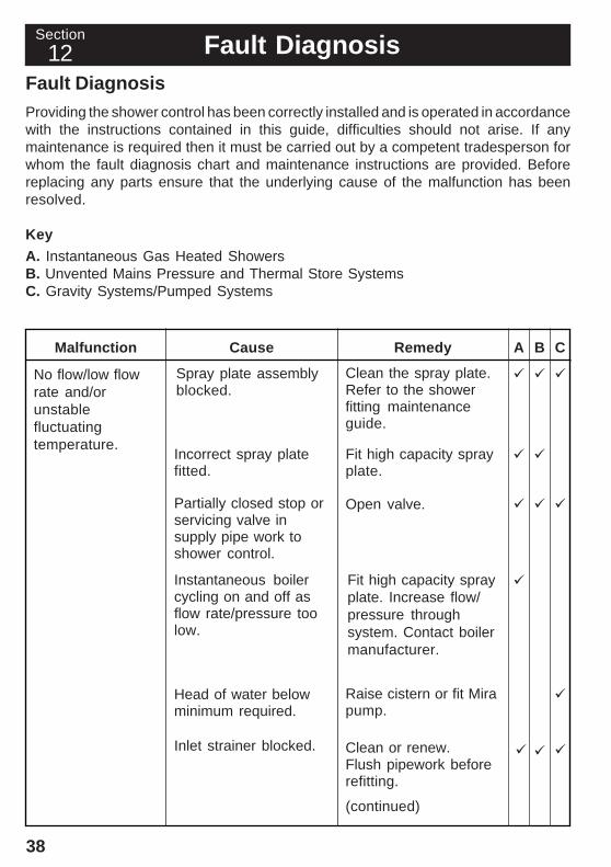
Providing the shower control has been correctly installed and is operated in accordancewith the instructions contained in this guide, difficulties should not arise. If anymaintenance is required then it must be carried out by a competent tradesperson forwhom the fault diagnosis chart and maintenance instructions are provided. Beforereplacing any parts ensure that the underlying cause of the malfunction has beenresolved.
Key
A. Instantaneous Gas Heated ShowersB. Unvented Mains Pressure and Thermal Store SystemsC. Gravity Systems/Pumped Systems
Cause RemedyMalfunction
No flow/low flowrate and/orunstablefluctuatingtemperature.
A B C
Spray plate assemblyblocked.
Clean the spray plate.Refer to the showerfitting maintenanceguide.
Incorrect spray platefitted.
Fit high capacity sprayplate.
Partially closed stop orservicing valve insupply pipe work toshower control.
Open valve.
Instantaneous boilercycling on and off asflow rate/pressure toolow.
Fit high capacity sprayplate. Increase flow/pressure throughsystem. Contact boilermanufacturer.
Head of water belowminimum required.
Raise cistern or fit Mirapump.
Inlet strainer blocked. Clean or renew.Flush pipework beforerefitting.
(continued)
SectionSection
12

39
Supply pressuresunequal.
Drip from handsetspray plateassembly or birspray plateassembly.
Maximum showertemperature toohot or too cold
Cause RemedyMalfunction A B C
Other hot or cold drawoffs being usedcausing wide pressurechanges orinstantaneous boilertemperature changes.
Do not use otheroutlets whilstshowering.
Cartridge assembly setfor high pressure in alow pressureapplication.
Refer to PressureSetting.
Refer to InstallationRequirements.
A small amount ofwater may be retainedin the shower fittingafter the showercontrol has beenturned off. This maydrain over a fewminutes.
Defective ceramicplates within theshower cartridge.
Renew the cartridgeassembly.
Maximum temperatureincorrectly set.
Reset the maximumtemperature. Refer toCommissioning:"MaximumTemperature Setting".
This is quite normal.Changing the angle ofthe shower fitting mayvary the draining time.
Check that thepressures are not inexcess of the maximumfor product (refer toFault Diagnosis "Flowcontrol knob stiff tooperate").

40
Cause RemedyMalfunction A B C
Showertemperature toocold (maximumtemperaturecorrectly set).
Hot water temperatureless than 12 °C abovethe required showerblend temperature.
Instantaneous boilernot igniting becausethe water flow rate istoo low.
Instantaneous boilernot igniting becausethe water pressure istoo low.
Adjust the hot watertemperature or wait forthe water to reheat ifstored system.
Fit high capacity sprayplate. Increase flow ratethrough the system.Check the cartridgeinlet filters, clean orreplace. Contact boilermanufacturer.
Increase waterpressure. Contactboiler manufacturer.
Leak from showercontrol body.
Cartridge inlet or outletseals missing ordamaged.
Fit new seals.
Cartridge damage dueto pressure build up.
Remove the back flowprevention device. Ifsystem constraintsmake this impractical fita domestic expansionvessel. If one is alreadyfitted, it may be deflatedand requirerepressurization. Ifnecessary, fit newcartridge.
Flow control knobstiff to operate.
Pressure build up. Thismay be due to waterexpansion caused bya backflow preventiondevice, such as PRVor non-return valve.
Remove the back flowprevention device. Ifsystem constraintsmake this impractical fita domestic expansionvessel. If one is alreadyfitted, it may be deflatedand requirerepressurization. Ifnecessary, fit newcartridge.(continued)

41
Cause RemedyMalfunction A B C
High inlet supplypressures.
Maximum maintainedpressure for showershould not exceed 5bar. If greater fit a droptight pressure reducingvalve (PRV) just afterthe property incomingmains stopcock,effectively balancingthe hot and cold supplypressures. Ideally setthe PRV to 3.5 bar.(Note information onbackflow preventiondevices in InstallationRequirements).
Select noisyduring operation.
Unbalanced inletsupply pressures.
Balance Select inletsupply pressures. Fit adrop tight PRV justafter the incomingmains stopcock,effectively balancingthe hot and cold supplypressures. Ideally setthe PRV to 3.5 bar.(Note information onbackflow preventiondevices in InstallationRequirements).
High inlet supplypressures.
Maximum maintainedpressure for showershould not exceed 5bar. If greater fit a droptight (PRV) installed asdetailed above.
Only full hot or fullcold available.
Reversed inletsupplies.
Refer to ReversedInlet Connections.
Inlet strainer blocked. Clean or renew.

42
Cartridge Assembly - Renewal
1. Refer to the Reversed Inlet Connections section and follow instructions 1. to8. inclusive to remove the cartridge assembly. Note the orientation of the red andblue tags on the cartridge assembly that identify the hot and cold inlets. Normallythe red tag will be on the left unless the cartridge assembly has been rotated forreversed supplies.
2. Insert the new cartridge assembly into the shower control body.
3. Refer to the Reversed Inlet Connections section and follow instructions 10. to15. inclusive to complete the installation of the new the cartridge assembly.
Cartridge Assembly 'O' Seals/Inlet Strainers - renewal
1. Refer to the Reversed Inlet Connections section and follow instructions 1. to8. inclusive to remove the cartridge assembly. Note the orientation of the red andblue tags on the cartridge assembly that identify the hot and cold inlets. Normallythe red tag will be on the left unless the cartridge assembly has been rotated forreversed supplies.
2. Renew the 'O' seals as necessary. Refer to the Spare Parts section for the sealpack details.
3. Clean or renew the inlet strainers as necessary. Refer to the Spare Parts sectionfor the strainer pack details. The inlet strainers must be fitted squarely and flushin the cartridge assembly inlet port. If necessary, flush the supply pipework toremove any residual debris. A flushing cartridge is available on request (refer toAccessories).
4. Insert the cartridge assembly into the shower control body.
5. Refer to the Reversed Inlet Connections section and follow instructions 10. to15. inclusive to complete the installation of the cartridge assembly.
Maintenance
CleaningMany household cleaners contain abrasives and chemical substances, and shouldnot be used for cleaning plated or plastic fittings. These finishes should be cleanedwith a mild washing up detergent or soap solution, and then wiped dry using a softcloth.
SectionSection
13

43
Section Accessories
Flushing Cartridge: A Flushing Cartridge is available from Mira Customer Supportfree of charge. This flushing Cartridge is designed to fit the surface mounted andbuilt-in products. It temporarily replaces the thermostatic cartridge assembly for thepurpose of flushing the incoming hot and cold water supply pipework after installationand before using the product. It also provides an ideal test point for measuring supplypressures (see "Measuring System Pressures" in the section InstallationRequirements).
Select Body
FlushingCartridge
Screw
Select Lever Controls (Part no. 617.35): Moulded from ABS plastic, designed toallow the Select shower control to be more easily operated by users with restrictedhand movement. Available from standard Select stockists.
SectionSection
14

44
Select Spare Parts List
280.07 Compression Fitting Kit410.51 Hub Pack421.12 Select Body421.31 Elbow Kit - components identified 'E'421.32 Trim/Knob Pack421.34 Backplate Kit - white - components identified 'D'553.35 Outlet Nipple617.16 Trim/Knob Pack Select - chrome617.34 Backplate Kit - chrome - components identified 'D'903.33 Cartridge Assembly932.16 Component Pack (as supplied) - components identified 'A'935.12 Seal Pack - components identified 'B'937.14 Screw Pack - components identified 'C'937.79 Strainer Pack
Spare PartsSectionSection
15

45
Select Spare Parts Diagram
421.32617.16
410.51
903.33
937.79
937.79
B, E
B
B
280.07
553.35
D
A
A
A
A
A
D
B
D
A
C, E
B
C
C
C
C
B
E421.12C, E
E
B, E

46
Select B Spare Parts List
004.66 Body030.67 RAC Elbow079.41 Building-in Shroud119.85 Support Bracket410.51 Hub Pack410.53 Concealing Plate Kit - white410.54 Concealing Plate Kit - chrome421.33 Trim/Knob Pack - white421.41 RAC Elbow Shroud - white552.07 1/2" BSP Parallel Nipple555.67 Outlet Nipple Assembly617.15 Trim/Knob Pack - chrome617.33 RAC Shroud & Wallplate - chrome617.36 Pushfit Adapter Kit807.28 Backplate Assembly903.33 Cartridge Assembly915.03 RAC Mounting Bush932.03 Component Pack (as supplied) - components identified 'D'932.04 15 mm Compression Fitting Pack935.12 Seal Pack - components identified 'B'937.14 Component Pack - components identified 'C'937.59 Screw Pack - components identified 'E'937.79 Strainer Pack938.04 RAC Wall Plate - white

47
Select B Spare Parts Diagram 079.41
410.53410.54
421.33617.15
932.04
932.04
555.67
903.33
410.51
937.79
937.79004.66
E
E
D
D
D
B
D, E
D B
CC
C
CB
D
C, D
CD, E
D
D
119.85
807.28
552.07
938.04617.33
915.03
030.67
421.41617.33
617.36
617.36
617.36
932.04
938.04617.33

P3273/3 (B73B) © Kohler Mira Limited, December 2007
Section Customer ServiceGuarantee of QualityMira Showers guarantee your product against any defect in materials or workmanship for the period shown in the Guarantee Registration Document included with your shower.Alternatively, to confi rm the applicable guarantee period please contact Customer Services.To validate the guarantee, please return your completed registration card.Within the guarantee period we will resolve defects, free of charge, by repairing or replacing parts or modules as we may choose.To be free of charge, service work must only be undertaken by Mira Showers or our approved agents.Service under this guarantee does not affect the expiry date.The guarantee on any exchanged parts or product ends when the normal product guarantee period expires.Not covered by this guarantee:Damage or defects arising from incorrect installation, improper use or lack of maintenance, including build-up of limescale.Damage or defects if the product is taken apart, repaired or modifi ed by any persons not authorised by Mira Showers or our approved agents.This guarantee is in addition to your statutory and other legal rights.
What to do if something goes wrongIf when you first use your shower, it doesn’t function correctly, fi rst contact your installer to check that installation and commissioning are satisfactory and in accordance with the instructions in this manual. We are on hand to offer you or your installer any advice you may need.Should this not resolve the diffi culty, simply contact our Customer Services Team who will give every assistance and, if necessary, arrange for our service engineer to visit. If the performance of your shower declines, consult this manual to see whether simple home maintenance is required. Please call our Customer Services Team to talk the diffi culty through, request a service under guarantee if applicable, or take advantage of our comprehensive After-Sales service.As part of our quality and training programme calls may be recorded or monitored.Our Customer Services Team is comprehensively trained to provide every assistance you may need: help and advice, spare parts or a service visit.
Spare PartsWe maintain an extensive stock of spares and aim to provide support throughout the product’s expected life.Spares can be purchased from approved stockists or merchants (locations on request) or direct from Customer Services.Spares direct will normally be despatched within two working days. Payment can be made by Visa or MasterCard at the time of ordering. Should payment by cheque be preferred, a pro-forma invoice will be sent.All spares are guaranteed for 12 months from date of purchase. Spares that have been supplied directly from us can be returned within one month from date of purchase, providing that they are in good order and the packaging is unopened.Note! Returned spares will be subject to a 15% restocking charge and authorisation must be obtained before return. Please contact our Customer Services Team.Note! In the interests of safety, spares requiring exposure to mains voltages can only be sent to competent persons.
ServiceOur Service Force is available to provide a quality service at a reasonable cost. You will have the assurance of a Mira trained engineer/agent, genuine Mira spare parts and a 12 month guarantee on the repair.Payment should be made directly to the engineer/agent using Visa, MasterCard or a cheque supported by a banker’s card.
To Contact UsEngland, Scotland, Wales and Northern IrelandMira Showers Customer ServicesTelephone: 0870 241 0888, Mon to Fri 8:00 am - 5:30 pm Sat 8:30 am - 3:30 pmE-mail: [email protected]: 01242 282595By Post: Cromwell Road, Cheltenham, Gloucestershire, GL52 5EPEireModern Plant Ltd (Dublin)Telephone: 01 459 1344, Mon to Fri 9:00 am - 5:00 pmE-mail: [email protected]: Dublin 01 459 2329Post: Otter House, Naas Road, Clondalkin, Dublin 22Modern Plant (Cork)Telephone: 021 496 8755, Mon to Fri 9:00 am - 5:00 pmE-mail: [email protected]: 021 496 8607Post: Tramore Road, Cork
Mira is a registered trade mark of Kohler Mira Limited.
The company reserves the right to alter product specifi cations without notice.
www.mirashowers.com