showerpower turbulator keeps igbts cool
TRANSCRIPT

Simcenter FLOEFD efficiently cools IGBT power modulesBy Klaus Olesen, Thermal Design Specialist, Danfoss Drives, Germany
The ShowerPower® liquid cooling heat exchange turbulator (figure 1) was designed in 2005 by Danfoss GmbH engineers to efficiently cool insulated-gate bipolar transistor (IGBT) power modules. The driver at the time was the fact that every electronic circuit gener-ates heat during normal operation (except perhaps for superconductivity scenarios, which are rare in industrial situations).
This heat generation is due to conduc-tive and switching losses in active devices as well as ohmic losses in conductor tracks. And since every new generation of power semiconductors becomes smaller than the preceding one, and the market expects smaller and more compact solutions, the demands to be met by the thermal design engineer keep growing.
Sufficient cooling of power electronics is therefore crucial for good operational performance. The dominant failure mechanisms in power semiconductor components are related not only to high absolute temperatures, but to changes in temperature during cycling; temperature swings produce thermo-mechanically induced stresses and strains in the material interfaces of the components (that have mismatches in coefficients of thermal expansion), which in turn lead to fatigue failures.
Liquid cooling of power electronics has been around for many years, primarily because of the ever-increasing power densities demanded, and due to the availability of liquids in certain applica-tions. Liquid cooling outperforms air cooling by producing heat transfer coefficients several orders of magnitude higher, thus enabling much higher power densities and more compact module and inverter solutions. The acceptance of liquid cooling varies between business segments. The auto-motive industry, for example, has been using liquid cooling for internal
siemens.com/simcenter
Challenges• Sufficiently cool power electronics for
operational performance
• Account for temperature changes during cycling
• Meet demands of design engineers
• Consider system corrosion, tightness, sedimentation and anti-freezing
Solutions• Provide several simulation cases so
designer can pick optimal design
• Support best design by comparing parametric results
• Consider many channel dimensions for a range of flow rates
• Predict surface temperatures before building a final prototype
• Danfoss ShowerPower liquid cooling heat exchange turbulator
• Simcenter FLOEFD for Creo CFD package
Siemens Digital Industries Software
ShowerPower turbulator keeps IGBTs coolSolution brief

combustion engines for more than a century, so the idea of liquid cooling of power electronics in an automotive application is considered a nonissue. In other industries the idea of having fluids flowing through power electronic assemblies often finds resistance and concerns. The term “turbulator” for the ShowerPower is a little misleading: under normal flow conditions, liquid flow in the flow channels is laminar; typical Reynolds numbers range around 500 and the transition into the turbu-lence regime occurs at a Reynolds number around 2,400.
Liquid cooling solutions may be divided into two groups – indirect and direct liquid cooling. Indirect cooling means the power module is assembled on a closed cooler; for example, a cold plate. Cold plates may be manufactured, for example, by gun drilling holes in alumi-num plates or by pressed-in copper tubes in aluminum extrusions. When dealing with cold plates, it is necessary to apply a layer of thermal interface material (TIM) between the power module and the cold plate. On the other hand, direct liquid cooling means the coolant is in direct contact with the surface to be cooled. Here the cooling efficiency is improved by increasing the surface area and this is commonly done by various pin fin designs. Direct liquid cooling (figure 2) eliminates the other-wise required layer of TIM. Because the TIM layer accounts for 30-to-50 percent of the Rth, junction-coolant, this TIM elimination results in an improved thermal environment for the power module. Since dominant failure mecha-nisms are temperature-driven, this leads to a more reliable power module.
The ShowerPower cooler assembly in figure 2 is for a wind turbine application featuring seven P3 IGBT modules, turbulators, sealings and a manifold. The design ensures that all chips in all modules are cooled equally efficiently. The concept enables tailored cooling if hot spots need extra attention; this is
simply done by designing the cooling channels individually. For further information on the principles of ShowerPower, please refer to refer-ences 1 and 2. The general ShowerPower plastic part (in blue) has several cooling cells in the X and Y directions and needs a manifold struc-ture on the backside of the plastic part;
Solution focus
this ensures that each cooling cell receives water at the same tempera-ture. Since the P3 module is relatively long and narrow, only one cell is neces-sary across the module; this makes the plastic part much simpler since the manifold structure on the backside becomes obsolete.
Figure 1: The general Danfoss ShowerPower turbulator concept (cooling liquid in blue and warmed up liquid in red).
Figure 2: Typical Danfoss ShowerPower turbulators (blue) and liquid cooling base plate for seven P3 power electronics modules in parallel.

• Eliminating the need for TIM – No TIM-related pump-out and dry-out effects
• A very low differential pressure drop
• Compact, low weight, high degree of design freedom enabling 3D designs
• Low manufacturing costs: metal- to-plastic conversion into simple plastic parts
Numerous computational fluid dynamics (CFD) simulations and test measurements have been done over the years on various Danfoss ShowerPower designs to validate the concept and extend it to niche and custom applica-tions. Engineering simulations (thermal, fluid, mechanical, stress, vibrational, etc.) are a crucial part in any power module product development project, the obvious reason being to reduce the number of time-consuming and costly experimental tests necessary. CFD is the best way to simulate a ShowerPower liquid cooling system. CFD can be used to predict fluid flow so the correct heat transfer rates and pressure drop condi-tions are found and the relevant temperatures (such as semiconductor junction temperatures) are calculated and maintained.
When designing a liquid cooled system in the Simcenter FLOEFD™ software for Creo CFD package (figure 3), we consider several issues in order to ensure a reliable solution that is capable of delivering the performance needed over the required lifetime of the system. We also consider other factors, such as corrosion, tightness, sedimentation (including bio growth) and anti-freezing issues. The permutations in the turbula-tor geometry are quite large:
• Width of channel
• Depth of channel
• Height of bypass
• Amount of channels per meande
• Channel cross-section area to avoid the risk of blockage
Figure 4 illustrates such a CFD prediction for a typical ShowerPower application. With Simcenter FLOEFD we can easily create several different simulation cases to allow the design engineer to make optimization judge-ments. Finding the best design out of many CFD cases is supported by effec-tively comparing parametric results in the software. We are able to look at
Figure 3: Typical Danfoss ShowerPower liquid cooling CFD simulation of power module geometry inside Simcenter FLOEFD for Creo.
Figure 4: Typical Danfoss ShowerPower liquid cooling CFD simulation of power module geometry showing sectional views of flow vectors and velocity magnitude contours.
Overall, the ShowerPower concept has several inherent benefits:
• The ability to homogeneously cool large flat baseplate power modules, and systems of modules, thereby eliminating temperature gradients, thus improving life and facilitating paralleling of many power chips
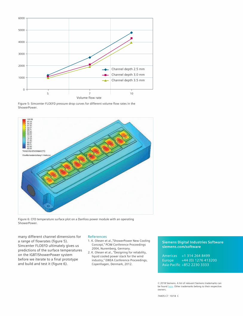
many different channel dimensions for a range of flowrates (figure 5). Simcenter FLOEFD ultimately gives us predictions of the surface temperatures on the IGBT/ShowerPower system before we iterate to a final prototype and build and test it (figure 6).
References1. K. Olesen et al.,”ShowerPower New Cooling
Concept,” PCIM Conference Proceedings 2004, Nuremberg, Germany.
2. K. Olesen et al., “Designing for reliability, liquid cooled power stack for the wind industry,” EWEA Conference Proceedings, Copenhagen, Denmark, 2012.
6000
5000
4000
3000
2000
1000
05 7 10
Figure 5: Simcenter FLOEFD pressure drop curves for different volume flow rates in the ShowerPower.
Figure 6: CFD temperature surface plot on a Danfoss power module with an operating ShowerPower.
Volume flow rate
Channel depth 2.5 mm
Channel depth 3.0 mm
Channel depth 3.5 mm
© 2018 Siemens. A list of relevant Siemens trademarks can be found here. Other trademarks belong to their respective owners.
74405-C7 10/18 C
Siemens Digital Industries Softwaresiemens.com/software
Americas +1 314 264 8499 Europe +44 (0) 1276 413200 Asia-Pacific +852 2230 3333