shreir's corrosion || corrosion of copper and its alloys
TRANSCRIPT
3.07 Corrosion of Copper and its AlloysC. D. S. TuckLloyd’s Register EMEA, London, UK
C. A. PowellCopper Development Association, Hemel Hemstead, UK
J. NuttallEuropean Copper Institute, Belgium
� 2010 Elsevier B.V. All rights reserved.
3.07.1 Introduction 1938
3.07.1.1 Alloy Compositions and Properties 1938
3.07.1.1.1 Coppers 1938
3.07.1.1.2 High conductivity coppers 1942
3.07.1.1.3 Heat treatable copper alloys 1942
3.07.1.1.4 Brasses 1942
3.07.1.1.5 Cupronickel alloys 1942
3.07.1.1.6 Tin bronze 1943
3.07.1.1.7 Aluminum–bronzes 1943
3.07.1.1.8 Silicon–bronzes 1943
3.07.1.1.9 Nickel silvers 1943
3.07.1.1.10 Copper–nickel–chromium 1943
3.07.2 Theoretical Aspects of Copper Corrosion 1943
3.07.2.1 Electrode Potential Relationships 1944
3.07.2.2 Behavior of Copper Electrodes 1944
3.07.3 Corrosive Environments Experienced 1946
3.07.3.1 Atmospheric Corrosion 1946
3.07.3.2 Soil Corrosion 1949
3.07.3.3 Corrosion in Natural Waters 1950
3.07.3.3.1 Impingement attack 1950
3.07.3.3.2 Dezincification of brasses 1952
3.07.3.3.3 Selective attack in other alloys 1954
3.07.3.3.4 Deposit attack and pitting 1954
3.07.3.4 Corrosion in Freshwater 1954
3.07.3.4.1 Pitting 1954
3.07.3.4.2 Chemical attack 1956
3.07.3.4.3 Microbiologically influenced corrosion 1956
3.07.3.4.4 Stress corrosion cracking 1957
3.07.3.4.5 Dissolution 1957
3.07.3.5 Corrosion in Seawater 1958
3.07.3.6 Effect of Exposure to Contaminated Environments 1960
3.07.3.6.1 Stress corrosion of brasses 1961
3.07.3.6.2 Stress corrosion of other copper alloys 1962
3.07.3.7 Corrosion in Industrial Chemicals 1962
3.07.3.7.1 Acid solutions 1963
3.07.3.7.2 Neutral and alkaline solutions 1963
3.07.3.7.3 Hydrogen sulfide pollution 1963
3.07.3.7.4 Other chemicals 1964
3.07.3.8 High Temperature Oxidation and Scaling 1965
3.07.3.8.1 High temperature oxidation of copper 1965
3.07.3.8.2 High temperature oxidation of copper alloys 1966
3.07.4 Protective Measures 1966
1937
1938 Non-Ferrous Metals and Alloys
3.07.5 Areas of Future Development 1967
3.07.5.1 Antimicrobial Benefits of Copper Corrosion 1967
3.07.5.2 Alloy Developments 1967
References 1968
GlossaryAntimicrobial Capable of destroying or inhibiting
the growth of microorganisms.
Dealloying A corrosion process whereby one
constituent of a metal alloy is preferentially
removed from the alloy, leaving an altered
residual microstructure.
Dezincification A corrosion process specific to
brasses (copper–zinc alloys) whereby
zinc is preferentially removed from the
alloy, resulting in a porous residual
microstructure.
Shape memory alloy An alloy which, after it is
deformed, will automatically regain its
original geometry when it is heated.
AbbreviationsBTAH Benzotriazole
FPSO Floating production, storage and offloading
vessel
MIC Microbiologically influenced corrosion
MRSA Meticillin-resistant Staphylococcus aureus
SCC Stress corrosion cracking
SEM Scanning electron microscopy
STEM Scanning transmission electron microscopy
WHO World Health Organization
SymbolsAi Activity of species i
K Equilibrium constant and rate constant
Q Activation energy
R Copper run-off rate
R Gas constant
T Temperature (K)
3.07.1 Introduction
Copper and copper alloys are among the earliestmetals known to man, as they have been used from
prehistoric times, and their present-day importanceis greater than ever before. Their widespread usedepends on a combination of good corrosion resis-tance in a variety of environments, excellent work-ability, high thermal and electrical conductivity, andattractive mechanical properties at low, normal, andmoderately elevated temperatures.
A wide range of cast and wrought alloys is avail-able. For detailed expositions of properties anduses, the reader is referred to publications of manyspecialized aspects obtainable from the CopperDevelopment Association offices in various countries.Relevant publications of the British StandardsInstitution include BSEN1982, Copper Alloy Ingots
and Castings,1 and those covering wrought products.2,3
All ASTM standards relating to copper and copperalloys are included in a volume published annually.4
3.07.1.1 Alloy Compositions and Properties
The mechanical properties of wrought alloys5,6
depend on composition and metallurgical condition.At the extremes, annealed pure copper has a tensilestrength of 220 MN m�2 and a hardness of 40 HV,and heat-treated beryllium copper can have a tensilestrength of 1450 MN m�2 and a hardness of 400 HV.Summaries of typical properties of some of the moreimportant wrought and cast copper alloys are givenin Tables 1–4.
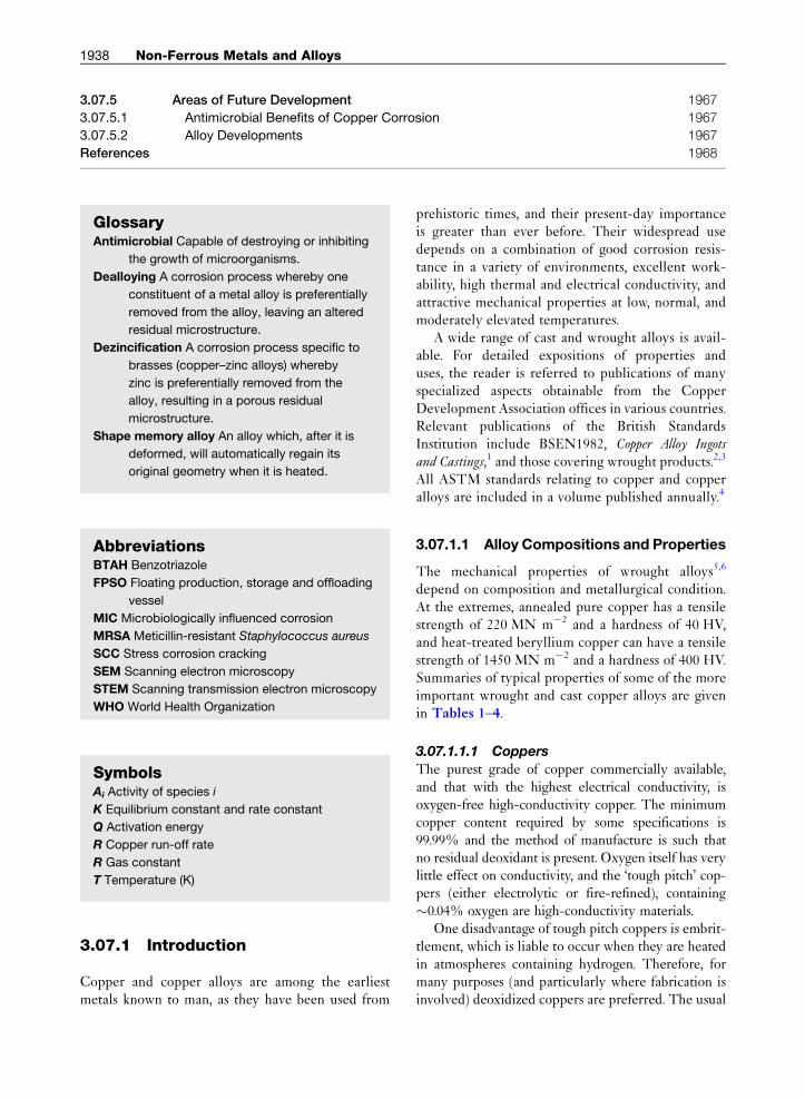
3.07.1.1.1 Coppers
The purest grade of copper commercially available,and that with the highest electrical conductivity, isoxygen-free high-conductivity copper. The minimumcopper content required by some specifications is99.99% and the method of manufacture is such thatno residual deoxidant is present. Oxygen itself has verylittle effect on conductivity, and the ‘tough pitch’ cop-pers (either electrolytic or fire-refined), containing�0.04% oxygen are high-conductivity materials.
One disadvantage of tough pitch coppers is embrit-tlement, which is liable to occur when they are heatedin atmospheres containing hydrogen. Therefore, formany purposes (and particularly where fabrication isinvolved) deoxidized coppers are preferred. The usual
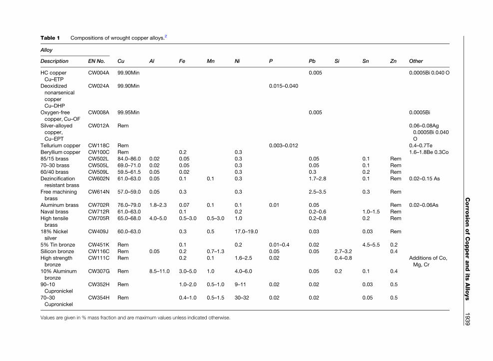
Table 1 Compositions of wrought copper alloys.2
Alloy
Description EN No. Cu Al Fe Mn Ni P Pb Si Sn Zn Other
HC copper
Cu–ETP
CW004A 99.90Min 0.005 0.0005Bi 0.040 O
Deoxidized
nonarsenical
copper
Cu–DHP
CW024A 99.90Min 0.015–0.040
Oxygen-free
copper, Cu–OF
CW008A 99.95Min 0.005 0.0005Bi
Silver-alloyedcopper,
Cu–EPT
CW012A Rem 0.06–0.08Ag0.0005Bi 0.040
O
Tellurium copper CW118C Rem 0.003–0.012 0.4–0.7Te
Beryllium copper CW100C Rem 0.2 0.3 1.6–1.8Be 0.3Co85/15 brass CW502L 84.0–86.0 0.02 0.05 0.3 0.05 0.1 Rem
70–30 brass CW505L 69.0–71.0 0.02 0.05 0.3 0.05 0.1 Rem
60/40 brass CW509L 59.5–61.5 0.05 0.02 0.3 0.3 0.2 Rem
Dezincificationresistant brass
CW602N 61.0–63.0 0.05 0.1 0.1 0.3 1.7–2.8 0.1 Rem 0.02–0.15 As
Free machining
brass
CW614N 57.0–59.0 0.05 0.3 0.3 2.5–3.5 0.3 Rem
Aluminum brass CW702R 76.0–79.0 1.8–2.3 0.07 0.1 0.1 0.01 0.05 Rem 0.02–0.06As
Naval brass CW712R 61.0–63.0 0.1 0.2 0.2–0.6 1.0–1.5 Rem
High tensile
brass
CW705R 65.0–68.0 4.0–5.0 0.5–3.0 0.5–3.0 1.0 0.2–0.8 0.2 Rem
18% Nickel
silver
CW409J 60.0–63.0 0.3 0.5 17.0–19.0 0.03 0.03 Rem
5% Tin bronze CW451K Rem 0.1 0.2 0.01–0.4 0.02 4.5–5.5 0.2
Silicon bronze CW116C Rem 0.05 0.2 0.7–1.3 0.05 0.05 2.7–3.2 0.4High strength
bronze
CW111C Rem 0.2 0.1 1.6–2.5 0.02 0.4–0.8 Additions of Co,
Mg, Cr
10% Aluminum
bronze
CW307G Rem 8.5–11.0 3.0–5.0 1.0 4.0–6.0 0.05 0.2 0.1 0.4
90–10
Cupronickel
CW352H Rem 1.0–2.0 0.5–1.0 9–11 0.02 0.02 0.03 0.5
70–30Cupronickel
CW354H Rem 0.4–1.0 0.5–1.5 30–32 0.02 0.02 0.05 0.5
Values are given in % mass fraction and are maximum values unless indicated otherwise.
Corro
sionofCopperandits
Allo
ys
1939

Table 2 Typical properties of wrought alloys
Alloy Meltingpoint (�C)
Density(g cm�3)
Coeff of expansion(� 10�6 �C�1)
ElectricalCond (%IACS)
Thermalconductivity (WmK�1)
TensileStrength (MNm�2)
Elongation(%)
Hardness(HV)
Description EN No.
HC copper Cu–ETP CW004A 1083 8.94 18 103 390 220–385 4–55 40–110Deoxidized
nonarsenical copper
Cu–DHP
CW024A 1082 8.93 18 80 340 220–385 4–60 40–120
Oxygen-free copper,
Cu–OF
CW008A 1083 8.94 18 100 395 220–385 4–60 40–110
Silver-alloyed copper,
Cu–EPT
CW012A 1083 8.94 18 102 390 220–385 4–55 40–110
Tellurium copper CW118C 1075 8.93 18 96 360 250–360 2–7 90–110
Beryllium copper CW100C 955 8.2 18 23 85 680–1450 3–35 100–400
85/15 Brass CW502L 1025 8.74 19 35 155 260–420 4–50 55–135
70–30 Brass CW505L 955 8.53 20 27 125 270–490 9–50 55–15060/40 Brass CW509L 905 8.38 21 29 125 340–480 6–43 85–140
Dezincification resistant
brass
CW602N 8.43 21 26 117 280–520 15–45 70–140
Free machining brass CW614N 8.47 21 27 120 350–450 20–30 100–150
Aluminum brass CW702R 980 8.33 19 23 100 300–390 25–35 70–110
Naval brass CW712R 890 8.41 21 25 110 340–460 10–30 85–140
High tensile brass CW705R 890 8.35 21 23 105 550–650 8–12 150–20018% Nickel silver CW409J 8.69 16 7 35 380–900 2–40 85–230
5% Tin bronze CW451K 1050 8.89 18 17 80 340–740 1–60 70–220
Silicon bronze CW116C 1030 8.52 18 8 40 380–900 3–50 90–220
High strength bronze CW111C 1060 8.86 17 50 220 600–800 5–15 100–25010% Aluminum bronze CW 307G 1075 7.5 18 8 40 430–770 15–25 200–240
90–10 cupronickel CW352H 1150 8.91 16 10 50 290–520 8–35 80–160
70–30 cupronickel CW354H 1240 8.94 16 5 30 350–520 12–35 90–130
1940
Non-F
erro
usMetals
andAllo
ys
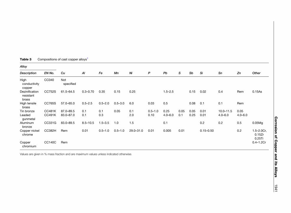
Table 3 Compositions of cast copper alloys1
Alloy
Description EN No. Cu Al Fe Mn Ni P Pb S Sb Si Sn Zn Other
High
conductivity
copper
CC040 Not
specified
Dezinificationresistant
brass
CC752S 61.5–64.5 0.3–0.70 0.35 0.15 0.25 1.5–2.5 0.15 0.02 0.4 Rem 0.15As
High tensilebrass
CC765S 57.0–65.0 0.5–2.5 0.5–2.0 0.5–3.0 6.0 0.03 0.5 0.08 0.1 0.1 Rem
Tin bronze CC481K 87.0–89.5 0.1 0.1 0.05 0.1 0.5–1.0 0.25 0.05 0.05 0.01 10.0–11.5 0.05
Leaded
gunmetal
CC491K 83.0–87.0 0.1 0.3 2.0 0.10 4.0–6.0 0.1 0.25 0.01 4.0–6.0 4.0–6.0
Aluminum
bronze
CC331G 83.0–89.5 8.5–10.5 1.5–3.5 1.0 1.5 0.1 0.2 0.2 0.5 0.05Mg
Copper nickel
chrome
CC382H Rem 0.01 0.5–1.0 0.5–1.0 29.0–31.0 0.01 0.005 0.01 0.15–0.50 0.2 1.5–2.0Cr,
0.15Zr0.25Ti
Copper
chromium
CC140C Rem 0.4–1.2Cr
Values are given in % mass fraction and are maximum values unless indicated otherwise.
Corro
sionofCopperandits
Allo
ys
1941
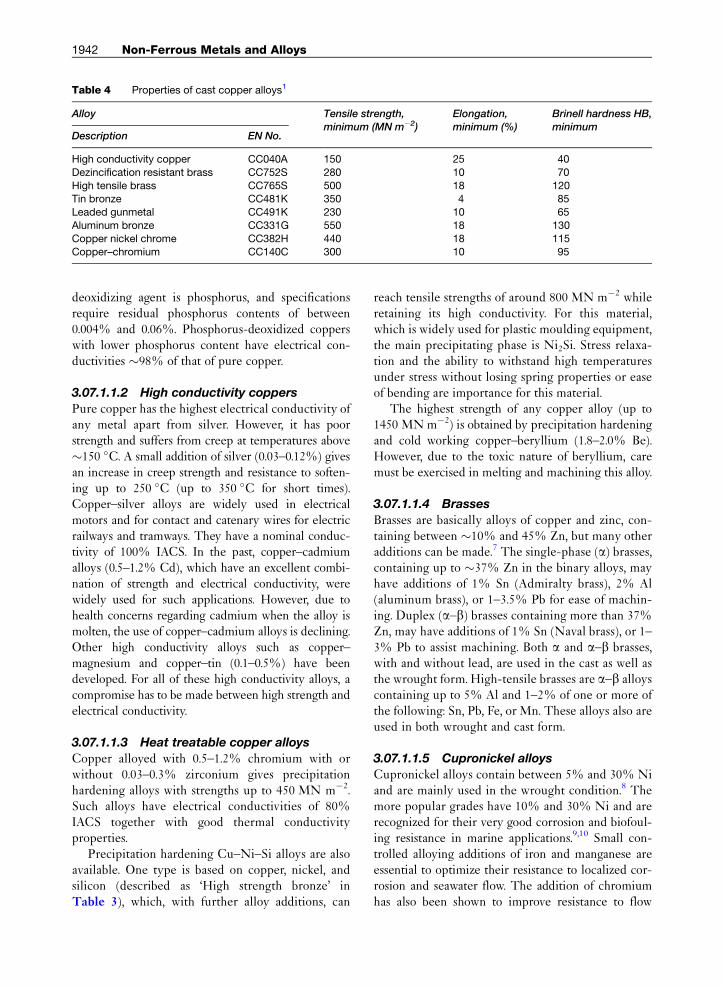
Table 4 Properties of cast copper alloys1
Alloy Tensile strength,minimum (MN m�2)
Elongation,minimum (%)
Brinell hardness HB,minimum
Description EN No.
High conductivity copper CC040A 150 25 40
Dezincification resistant brass CC752S 280 10 70
High tensile brass CC765S 500 18 120Tin bronze CC481K 350 4 85
Leaded gunmetal CC491K 230 10 65
Aluminum bronze CC331G 550 18 130
Copper nickel chrome CC382H 440 18 115Copper–chromium CC140C 300 10 95
1942 Non-Ferrous Metals and Alloys
deoxidizing agent is phosphorus, and specificationsrequire residual phosphorus contents of between0.004% and 0.06%. Phosphorus-deoxidized copperswith lower phosphorus content have electrical con-ductivities �98% of that of pure copper.
3.07.1.1.2 High conductivity coppers
Pure copper has the highest electrical conductivity ofany metal apart from silver. However, it has poorstrength and suffers from creep at temperatures above�150 �C. A small addition of silver (0.03–0.12%) givesan increase in creep strength and resistance to soften-ing up to 250 �C (up to 350 �C for short times).Copper–silver alloys are widely used in electricalmotors and for contact and catenary wires for electricrailways and tramways. They have a nominal conduc-tivity of 100% IACS. In the past, copper–cadmiumalloys (0.5–1.2% Cd), which have an excellent combi-nation of strength and electrical conductivity, werewidely used for such applications. However, due tohealth concerns regarding cadmium when the alloy ismolten, the use of copper–cadmium alloys is declining.Other high conductivity alloys such as copper–magnesium and copper–tin (0.1–0.5%) have beendeveloped. For all of these high conductivity alloys, acompromise has to be made between high strength andelectrical conductivity.
3.07.1.1.3 Heat treatable copper alloys
Copper alloyed with 0.5–1.2% chromium with orwithout 0.03–0.3% zirconium gives precipitationhardening alloys with strengths up to 450 MN m�2.Such alloys have electrical conductivities of 80%IACS together with good thermal conductivityproperties.
Precipitation hardening Cu–Ni–Si alloys are alsoavailable. One type is based on copper, nickel, andsilicon (described as ‘High strength bronze’ inTable 3), which, with further alloy additions, can
reach tensile strengths of around 800 MN m�2 whileretaining its high conductivity. For this material,which is widely used for plastic moulding equipment,the main precipitating phase is Ni2Si. Stress relaxa-tion and the ability to withstand high temperaturesunder stress without losing spring properties or easeof bending are importance for this material.
The highest strength of any copper alloy (up to1450 MNm�2) is obtained by precipitation hardeningand cold working copper–beryllium (1.8–2.0% Be).However, due to the toxic nature of beryllium, caremust be exercised in melting and machining this alloy.
3.07.1.1.4 Brasses
Brasses are basically alloys of copper and zinc, con-taining between �10% and 45% Zn, but many otheradditions can be made.7 The single-phase (a) brasses,containing up to �37% Zn in the binary alloys, mayhave additions of 1% Sn (Admiralty brass), 2% Al(aluminum brass), or 1–3.5% Pb for ease of machin-ing. Duplex (a–b) brasses containing more than 37%Zn, may have additions of 1% Sn (Naval brass), or 1–3% Pb to assist machining. Both a and a–b brasses,with and without lead, are used in the cast as well asthe wrought form. High-tensile brasses are a–b alloyscontaining up to 5% Al and 1–2% of one or more ofthe following: Sn, Pb, Fe, or Mn. These alloys also areused in both wrought and cast form.
3.07.1.1.5 Cupronickel alloys
Cupronickel alloys contain between 5% and 30% Niand are mainly used in the wrought condition.8 Themore popular grades have 10% and 30% Ni and arerecognized for their very good corrosion and biofoul-ing resistance in marine applications.9,10 Small con-trolled alloying additions of iron and manganese areessential to optimize their resistance to localized cor-rosion and seawater flow. The addition of chromiumhas also been shown to improve resistance to flow
Corrosion of Copper and its Alloys 1943
velocity and a cast (30Ni–1.6Cr)11 as well as a wroughtversion (16Ni–0.5Cr)12 have been developed. The castversion has been predominantly used by the BritishNavy and is covered by DEF STAN 02-824.11
Other higher strength cupronickels have additionsof aluminum or tin, producing two ranges of pro-ducts. The Cu–Ni–Al alloys13 are thermally age-hardened to form Ni3Al precipitates in the matrixwhereas Cu–Ni–Sn alloys display spinodal strength-ening through the development of submicroscopicchemical composition fluctuations.14
3.07.1.1.6 Tin bronzeCopper alloys with 1.5–9% Sn and 0.01–0.4% P arewrought alloys known as phosphor bronzes. Theyhave good elastic properties combined with goodresistance to corrosion and corrosion fatigue.
Cast copper alloys with between 2% and 11% Snand 1–10% Zn are termed gunmetals. Modifiedforms may contain lead (up to 7%) giving leadedgunmetal or nickel (up to 6%) giving a nickel gun-metal. Gunmetals are the most widely used coppercasting alloys combining good corrosion resistancewith modest strength and good castability.
3.07.1.1.7 Aluminum–bronzes
Wrought aluminum bronzes contain between 4% and12.5% Al. If less than 8% Al is present, the alloys area-phase and may be cold worked. The two phase(a–b) alloys, which may be wrought or cast, contain8–12.5% Al with possible additions of iron (0.5–7%),manganese (1.5–3.5%), nickel (2–7%), and silicon(2%). In terms of its influence on corrosion resis-tance, the addition of nickel is the most important,as it acts to reduce dealuminification (see Section3.07.3.3.3).
Aluminum bronzes can be hardened by heat treat-ment and have an enhanced corrosion resistance dueto the existence of a complex naturally-formed pro-tective film which includes both aluminum oxide15
and copper oxide. If damaged, the film is self healingand this gives aluminum bronzes good wear, cavita-tion, and antigalling characteristics.
3.07.1.1.8 Silicon–bronzes
Silicon–bronzes usually contain 2.8–4.5% Si and0.8–1.5% Mn. The wrought alloys combine high ten-sile strength (see Table 2) with good corrosion resis-tance and an attractive color. Theyare used in chemicalequipment and marine hardware. The cast alloy hasfound application in statuary, art castings, and plaques.
3.07.1.1.9 Nickel silversNickel silvers do not contain silver but are essentiallycopper–zinc brasses with nickel in the range of9–18%. The 18% nickel alloy polishes to a whitecolor (like silver) and has good corrosion resistance.All have excellent ductility and are available as tube,wire, plate, sheet, and strip.
3.07.1.1.10 Copper–nickel--chromiumCopper–nickel–chromium alloys have been devel-oped chiefly as cast alloys, the most prominent ofwhich is CC382H. A version of this is DEF STAN02-824, which is commonly used by the British Navy.
3.07.2 Theoretical Aspects of CopperCorrosion
Copper is the first member of Group IB of the peri-odic table, having atomic number 29 and electronicconfiguration [Ar]3d104s1. Loss of the outermosts electron gives the cuprous ion Cu+ and a secondelectron may be lost from the filled d shell to form thecupric ion Cu2+. The availability of the d electronsfor coordination allows copper to readily form com-plexes with such species as NH3 and CN.
Copper occurs in the uncombined state in natureand is relatively easily obtained by the reduction of itscompounds. It is not very active chemically and oxi-dizes very slowly in air at ordinary temperatures. Inthe electrochemical series of elements, copper is nearthe noble end and will not normally displace hydro-gen, even from acid solutions. Indeed, if hydrogen isbubbled through a solution of copper salts, copper isslowly deposited, a process which occurs more rap-idly if it is carried out under pressure.
As copper is not an inherently reactive element, itis not surprising that the rate of corrosion, even ifunhindered by films of insoluble corrosion products,is usually low. Nevertheless, although the breakdownof a protective oxide film on copper is not likely tolead to such rapid attack as with a more reactivemetal (e.g., aluminum), in practice the good behaviorof copper, and, more particularly, of some of its alloysoften depends to a considerable extent upon themaintenance of a protective film of oxide or otherinsoluble corrosion product.
In many environments, alloys of copper can bemore resistant to corrosion than is copper itself,owing to the incorporation either of relatively corro-sion-resistant metals, such as nickel or tin, or ofmetals such as aluminum or beryllium which would
1944 Non-Ferrous Metals and Alloys
be expected to assist in the formation of protectiveoxide films. Several types of copper alloys are liableto undergo a selective type of corrosion in certaincircumstances, the most notable example being thedezincification of brasses (see Section 3.07.3.3.2).Some alloys are liable to suffer stress corrosion bythe combined effects of internal or applied stressesand the corrosive effects of certain specific environ-ments. The most widely known example of this is theseason cracking of brasses (see Section 3.07.3.6). Ingeneral, brasses are the least corrosion-resistant ofthe commonly used copper-based alloys.
The various grades of commercial copper avail-able do not differ to any marked extent in theircorrosion resistance, and a choice between them isusually based on other grounds. Subsequent refer-ences to the corrosion behavior of copper may there-fore be taken to apply broadly to all types of copper.The choice of alloy for any particular applicationis determined by the desired physical, mechanical,and metallurgical properties. Within these limits,however, a range of materials is usually available.It is essential that, at the very earliest stage, thechoice of materials and the detail of design of theinstallation should be considered from the point ofview of corrosion if the best performance is to beobtained in service. This is particularly true forcopper alloys, where protective measures are notnormally applied.
3.07.2.1 Electrode Potential Relationships
The electrode potentials for the equilibria:
Cu2þ þ 2e⇆Cu ½1�Cuþ þ e⇆Cu ½2�Cu2þ þ e⇆Cuþ ½3�
are þ0.34, þ0.52, and þ 0.17 V respectively, asmeasured against a standard hydrogen electrode.For the equilibrium
2Cuþ⇆Cu2þ þ Cu ½4�Kc ¼ aCu2þ= a2Cuþ
� �2
Kc has the value of�1� 106 at 298 K, and in solutionsof copper ions in equilibrium with metallic copper,cupric ions therefore greatly predominate overcuprous ions, except in very dilute solutions. Cupricions are therefore normally stable and become unstableonly when the cuprous ion concentration is very low.A very low concentration of cuprous ions may beproduced in the presence of a suitable anion, by theformation of either an insoluble cuprous salt or a very
stable complex cuprous ion. Cuprous salts can there-fore exist in contact with water only if they are verysparingly soluble (e.g., cuprous chloride) or are com-bined in a complex, for example, [Cu(CN)2]
� and[Cu(NH3)2]
+. Cuprous sulfate can be prepared innonaqueous conditions, but because it is not spar-ingly soluble in water, it is immediately decomposedby water to copper and cupric sulfate. The equilib-rium between copper and cuprous and cupric ion isdisturbed by the presence of oxygen in solution, sincethe reaction shown in eqn [3] is facilitated, the oxygenacting as an electron acceptor.
3.07.2.2 Behavior of Copper Electrodes
The electrode potential behavior of copper in varioussolutions has been investigated in detail by Gatty andSpooner.16 According to these workers a large part ofthe surface of copper electrodes in aerated aqueoussolutions is normally covered with a film of cuprousoxide and the electrode potential is usually close tothe potential of these film-covered areas. The filmedmetal simulates a reversible oxygen electrode at theoxygen concentration and pH, less an overvoltagedetermined by the existing current density. The prin-cipal factors which affect the electrode potential arethus the nature of the solution, the way in which thisinfluences the area of oxide film, and the supply ofoxygen to the metal surface. In solutions containingchloride, there is a tendency for the establishmentof the Cu/CuCl/Cl� electrode potential, so thatthe activity of chloride ions is an important factor indetermining the electrode behavior. From a knowl-edge of the solubility products of cuprous chlorideand cuprous oxide, it is possible to predict underwhat conditions chloride or hydroxyl ions are thepotential-determining ions. According to Gattyand Spooner, chloride determines the potential ifaOH� < 10�8:1 � aCl� and hydroxyl determines thepotential if aOH� > 10�8:1 � aCl� . However, this willnot hold in concentrated solutions as complex[CuCl2]
� ions as well as simple ions will be present.A further factor to be considered is the ready formationof insoluble basic compounds. In solutionswhich do notcontain chloride (e.g., sulfate or nitrate solutions), cor-rosion rates are usually lower and the electrode poten-tial is more steady over a wide range of conditions.
Gatty and Spooner consider that the rate of cor-rosion is probably determined by the rate at whichmetal ions can escape through pores in the protectiveoxide film, and this is supported by the results of
Corrosion of Copper and its Alloys 1945
experiments on the anodic and cathodic polarizationof copper.
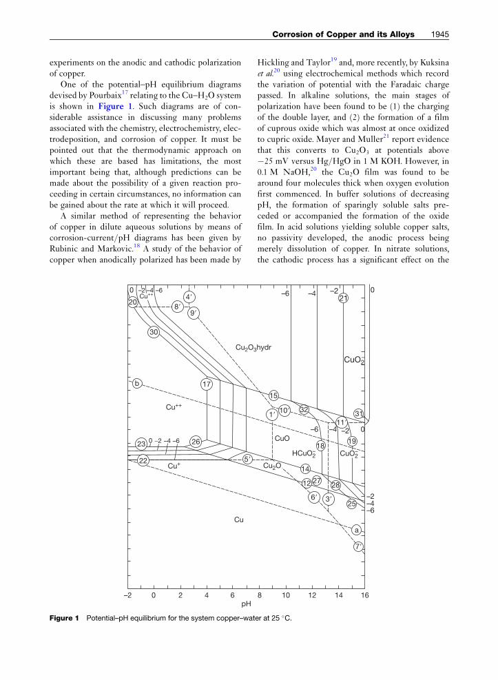
One of the potential–pH equilibrium diagramsdevised by Pourbaix17 relating to the Cu–H2O systemis shown in Figure 1. Such diagrams are of con-siderable assistance in discussing many problemsassociated with the chemistry, electrochemistry, elec-trodeposition, and corrosion of copper. It must bepointed out that the thermodynamic approach onwhich these are based has limitations, the mostimportant being that, although predictions can bemade about the possibility of a given reaction pro-ceeding in certain circumstances, no information canbe gained about the rate at which it will proceed.
A similar method of representing the behaviorof copper in dilute aqueous solutions by means ofcorrosion-current/pH diagrams has been given byRubinic and Markovic.18 A study of the behavior ofcopper when anodically polarized has been made by
b
Cu2O3
30
9�
5�
4�
8�20
17
22
23 260 -2 –4 –6
Cu+
Cu++
Cu++
Cu
–2 0 2 4 6pH
0 –2 –4 –6
Figure 1 Potential–pH equilibrium for the system copper–wat
Hickling and Taylor19 and, more recently, by Kuksinaet al.20 using electrochemical methods which recordthe variation of potential with the Faradaic chargepassed. In alkaline solutions, the main stages ofpolarization have been found to be (1) the chargingof the double layer, and (2) the formation of a filmof cuprous oxide which was almost at once oxidizedto cupric oxide. Mayer and Muller21 report evidencethat this converts to Cu2O3 at potentials above�25 mV versus Hg/HgO in 1 M KOH. However, in0.1 M NaOH,20 the Cu2O film was found to bearound four molecules thick when oxygen evolutionfirst commenced. In buffer solutions of decreasingpH, the formation of sparingly soluble salts pre-ceded or accompanied the formation of the oxidefilm. In acid solutions yielding soluble copper salts,no passivity developed, the anodic process beingmerely dissolution of copper. In nitrate solutions,the cathodic process has a significant effect on the
hydr
CuO2–
1�10�
11�
6� 3�
21
32
7�
CuO
Cu2O
–2–4–6
15
14
12 2728
18
31
25
a
19
HCuO2– CuO2
–
–2 0–4–6
8 10 12 14 16
0
–2–4–6
er at 25 �C.

1946 Non-Ferrous Metals and Alloys
anodic dissolution of copper. Low-frequency ACpolarization techniques have shown22 that OH� ionsadsorbed during the cathodic half-cycle facilitatecopper dissolution in the anodic half-cycle throughthe production of an insoluble hydroxide layer. Otherworkers have also studied the anodic behavior ofcopper or copper alloys in alkaline23 and in acid24,25
solutions, using both static conditions and turbulentconditions, such as those generated by rotating cylin-der electrodes26 and the presence of light has beenfound to have an influence on the electrochemistry.21
For instance, in Cu–Al–Sn anodically polarized insodium sulfate solution,27 an enrichment of the pas-sive film with aluminum oxide can be detected as thephotocurrent spectrum changes from a ‘copper-type’to an ‘aluminum-type’ with time.
The excellent corrosion resistance of cupronickelalloys is related to the formation of a particularlyeffective protective film of corrosion products in theearly stages of exposure. A number of studies havebeen carried out involving a wide range of analyticaltechniques.28 The film formed is dark brown in colorand there is general agreement that it contains aninner layer of Cu2O which is enriched with nickeland iron. Recent electrochemical studies29 have iden-tified that over this layer, a thin outer layer of CuOdevelops and an increasing nickel content in the alloyproduces a decrease in the overall corrosion rate. Thecorrosion rate also falls as the chloride ion concen-tration rises above 0.3 M due to an enhanced forma-tion of the passive Cu2O film.30 On this subject, in aseawater context, see Section 3.07.3.5.
3.07.3 Corrosive EnvironmentsExperienced
Copper and its alloys have a very diverse range ofproperties and their application exposes them tomany types of environment. Artifacts dating backthousands of years are testimony to the resilience ofcopper alloys to atmospheric corrosion, waters, andsoils. Also, they have been recognized for marine usefor several decades and are still selected even thoughother noncopper alloy systems have been developedin the interim. The release of copper ions and thecuprous oxide film have antifouling properties and, inaddition, recent work has proved their antimicrobialproperties; investigations into the mechanisms forthese beneficial effects are ongoing, as are theirdevelopment into new applications. More traditionalapplications requiring corrosion resistance of copper
alloys involve roofing, plumbing, naval and commer-cial shipping, and desalination plant. The level ofcorrosion and corrosion mechanisms occurring indifferent environments depend on the alloy groupchosen and can vary from mildly resistant to highlyresistant. Various corrosion mechanisms exist andthese have been found to be related to the type ofalloy and to the environment to which it is exposed.The following sections give details of the effects seenin a range of different corrosive environmentsexperienced.
3.07.3.1 Atmospheric Corrosion
Copper has a high degree of resistance to atmo-spheric corrosion and is widely used for roofingsheets, flashings, gutters, and conductor wires aswell as for statues and plaques. The corrosion resis-tance of copper and its alloys is due to the develop-ment of protective layers of corrosion products,which act to reduce the subsequent rate of attack.The formation, in course of time, of the typical green‘patina’ gives copper roofs a pleasing appearance;indeed, methods are used to produce it artificiallyor to accelerate its formation.31 The nature of thecorrosion products formed on copper exposed to theatmosphere has been exhaustively studied by Vernonand Whitby.31–33 A comprehensive review of the lit-erature on atmospheric corrosion including copperand copper alloys up to 1995 has been produced byDechema34 It has been found that in the early periodsof exposure, the corrosion deposit contains sulfide,oxide, and soot. By the action of sulfuric acid and bythe oxidation of sulfide, copper sulfate is formed andthis hydrolyzes and forms a coherent and adherentbasic form of this compound. Initially, this approxi-mates to CuSO4–Cu(OH)2 but it gradually increasesin basicity until after 70 years or so it becomesCuSO4–3Cu(OH)2 and is identical with the mineralbrochantite. In some cases, small quantities of basiccarbonate, CuCO3–Cu(OH)2 (malachite), are alsopresent, and, near the sea coast, basic chlorideCuCl2–3Cu(OH)2 (atacamite) is produced. However,even very near the sea coast, sulfate usually predo-minates over chloride.
In laboratory tests, Vernon33 showed that the rela-tive humidity and the presence of sulfur dioxide havea profound effect on the rate of corrosion of copper,as they do with many other metals. He found thatwhen the relative humidity was less than 63%, therewas little attack even in the presence of much sulfurdioxide, but when the relative humidity was raised to
Corrosion of Copper and its Alloys 1947
75%, corrosion became severe and increased with theconcentration of sulfur dioxide present. By exposingspecimens to the atmosphere at different times of theyear, Vernon found that the rate of attack on copperwas determined by the conditions prevailing at thetime of first exposure. For specimens first exposed inwinter, there was a linear relationship betweenincrease in weight and time of exposure, indicatingthat the layer of corrosion product formed underthese conditions was nonprotective. For specimensfirst exposed in summer, the square of the increasein weight was proportional to the time of exposure.This indicated that the coating formed in summer(when the atmospheric pollution was relatively low)was protective. It was found that the parabolic lawholds when the corrosion product layer obstructs theaccess of the corrosive agent to the metal, the rate ofattack then being inversely proportional to the thick-ness of the layer. It was apparent that the protectivecharacter of the layer persisted through subsequentperiods when the pollution was relatively high.
Copper tarnishes rapidly when exposed to atmo-spheres containing hydrogen sulfide. Atmosphericcorrosion tests on copper and several copper alloyswere carried out by Hudson35 at a number of sites inthe United Kingdom. Corrosion damage was assessedby one or more of the following methods: gain inweight, loss of weight after cleaning, loss of electricalconductivity, and loss of tensile strength. Hudsonfound that the resistance to atmospheric corrosionwas high and that the rate of attack tended to de-crease with time of exposure. Little difference wasfound between the behavior of arsenical copper andhigh-conductivity copper, and most of the alloys
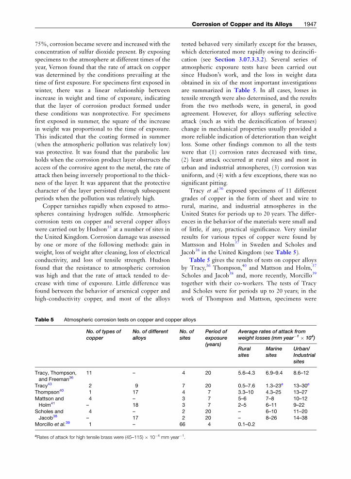
Table 5 Atmospheric corrosion tests on copper and coppe
No. of types ofcopper
No. of differentalloys
Tracy, Thompson,and Freeman36
11 –
Tracy43 2 9
Thompson40 1 17
Mattson andHolm41
4 –– 18
Scholes and
Jacob384 –
– 17Morcillo et al.39 1 –
aRates of attack for high tensile brass were (45–115) � 10�4 mm year�
tested behaved very similarly except for the brasses,which deteriorated more rapidly owing to dezincifi-cation (see Section 3.07.3.3.2). Several series ofatmospheric exposure tests have been carried outsince Hudson’s work, and the loss in weight dataobtained in six of the most important investigationsare summarized in Table 5. In all cases, losses intensile strength were also determined, and the resultsfrom the two methods were, in general, in goodagreement. However, for alloys suffering selectiveattack (such as with the dezincification of brasses)change in mechanical properties usually provided amore reliable indication of deterioration than weightloss. Some other findings common to all the testswere that (1) corrosion rates decreased with time,(2) least attack occurred at rural sites and most inurban and industrial atmospheres, (3) corrosion wasuniform, and (4) with a few exceptions, there was nosignificant pitting.
Tracy et al.36 exposed specimens of 11 differentgrades of copper in the form of sheet and wire torural, marine, and industrial atmospheres in theUnited States for periods up to 20 years. The differ-ences in the behavior of the materials were small andof little, if any, practical significance. Very similarresults for various types of copper were found byMattsson and Holm37 in Sweden and Scholes andJacob38 in the United Kingdom (see Table 5).
Table 5 gives the results of tests on copper alloysby Tracy,36 Thompson,40 and Mattson and Holm,37
Scholes and Jacob38 and, more recently, Morcillo39
together with their co-workers. The tests of Tracyand Scholes were for periods up to 20 years; in thework of Thompson and Mattson, specimens were
r alloys
No. ofsites
Period ofexposure(years)
Average rates of attack fromweight losses (mm year�1 � 104)
Ruralsites
Marinesites
Urban/Industrialsites
4 20 5.6–4.3 6.9–9.4 8.6–12
7 20 0.5–7.6 1.3–23a 13–30a
4 7 3.3–10 4.3–25 13–27
3 7 5–6 7–8 10–123 7 2–5 6–11 9–22
2 20 – 6–10 11–20
2 20 – 8–26 14–3866 4 0.1–0.2
1.

1948 Non-Ferrous Metals and Alloys
removed after 2 and 7 years and further specimenswere removed after 16 years.41 The average penetra-tion during the 16-year period was found to be aboutthe same as during the first 7 years, but considerablylower than during the initial 2 years. The materialstested included brass, nickel–silvers, cupronickels,copper–beryllium alloys, and various bronzes. Recentstudies have involved the investigation of seasonaleffects of industrial pollutants (NOx) and comparisonof rural and marine locations in South America.42
In the tests described by Tracy,43 a high-tensilebrass suffered severe dezincification (see Table 5).The loss in tensile strength for this material was100% and, for a non-arsenical 70–30 brass, 54%; noother material lost more than 23% during 20 years’exposure. In Mattsson and Holm’s tests, the highestcorrosion rates were also shown by some of the brasses.Dezincification caused losses of tensile strength of upto 32% for a b brass and up to 12% for some of thea–b brasses; no other materials lost more than 5% in7 years. Dezincification also occurred, though to alesser degree, in the a brasses tested, even in a materialwith as high a copper content as 92%. Incorporation ofarsenic in the a brasses consistently prevented dezin-cification only in marine atmospheres.
In Thompson’s reported work, the alloy showingthe lowest rate of attack at all sites was a bronzecontaining 7Al–2Si. Relatively high corrosion rateswere shown by Cu–5Sn–0.2P at a marine site andCu–2.5Co–0.5Be in an industrial environment. Theberyllium–copper alloys were the only materialsto show measurable pitting, the deepest attackbeing 0.6 mm after 7 years. In Scholes and Jacob’stests pitting, intergranular (or transgranular) penetra-tion, or selective attack occurred on some alloys.The maximum depth of attack exceeded 0.2 mm in20 years on 6 of the 21 materials (three brasses, twonickel silvers, and Cu–20Ni–20Mn), but exceeded0.5 mm in 20 years only on Cu–20Ni–20Mn and60/40 brass. These two latter alloys lost up to 73%and 13% respectively of their tensile strength; noother alloys lost more than 10% in 20 years.
The work of Ramos et al.42 has demonstrated aclear correlation between seasonal increases in SO2
and NOx concentrations in urban atmospheres withhigher corrosion rates and the presence of sulfatesin the corrosion products. This broadly agreed witha previous study of comparative weight gains of cop-per over a 2-year period at 39 sites spread acrossEurope,44 where a clear correlation was foundbetween weight gain and SO2 content of the environ-ment, although attempts to find mathematical
correlations of weight increase with other atmo-spheric species was not found to be possible. How-ever, other works report that the corrosion of copperby sulfur dioxide is measurably accelerated by thepresence of NO2
45 or ozone.46 The recent studyconducted in South America, which involved thecomparison of 21 unpolluted sites with 45 marinelocations, showed that there is a threshold chlorideconcentration of 20 mg m�2 day�1 in the environ-ment above which the corrosion rate intensifies.Other recent studies have involved comparing theeffects of different types of climates throughout fourcontinents.47
From the work described and other investiga-tions,48 it is evident that copper and most copperalloys are highly resistant to atmospheric corrosion.The reported results indicate that copper itself is asgood as, or better than, any of the alloys with regardto atmospheric corrosion. Some of the brasses areliable to suffer rather severe dezincification and it isunwise to expose these to the more corrosive atmo-spheres without applying some protection.
When unusually rapid corrosion of copper and itsalloys occurs during atmospheric exposure, it is likelyto be for one of the following reasons:
1. Extreme local pollution by products ofcombustion.
2. Bad design or construction, for example, the pres-ence of crevices where moisture may lodge forlong periods, including, for instance, coiled wire.49
3. Constant dripping of rain water contaminated byatmospheric pollution (e.g., from near-by chimneystacks) or by organic acids from lichens, etc.
4. Corrosion fatigue due to inadequate allowance forexpansion and contraction with consequent buck-ling as the temperature fluctuates.
Most of these disorders can be avoided by attentionto design.50
The discussions in recent years of the possibilityof pollution occurring as a result of released copperdue to atmospheric corrosion have resulted in studiesof runoff from roofs and facades by several work-ers.51–54 A number of research results have beenpublished by the Royal Institute of Technology,Stockholm, Sweden55–61 and the EMPA laboratories,Switzerland. It has been found that, after a shortinitiation period, the runoff rate of copper per yearis constant over a long time.55,56,58,62 This makes itpossible to model the copper runoff rate, R,57 basedon SO2 concentration, the pH of the rainwater, and itsquantity. The roof surface angle of inclination Y has

Corrosion of Copper and its Alloys 1949
also been taken into account,61 according to the fol-lowing equation:
R¼ð0:37½SO2�0:5þ0:95½Rain�10�0:62pHÞ ðcosYÞðcos 45�Þ ½5�
The seasonal variation of copper corrosion rate andthe runoff rate have also been studied.60
Some workers note that the released metal fromthe corrosion reaction is in ionic form directly on theroof and the environmental impact of these releasedions has been determined. Other workers state thatthe run-off is mainly in particulate form. However,the interaction with solid surfaces in the near vicinityof buildings has been looked at together with thechanges of transport which occur from the source tothe end product. Investigations of reactivity havebeen made toward various natural and manmadesurfaces, such as different soil systems, limestone,and concrete. The results illustrate that, for scenarioswhere copper ions come in extensive contact withsolid surfaces, a large fraction of released copper isretained in the immediate vicinity of the building.56
The potential ecotoxic effects from released copperhave also been investigated. Copper biosensor testingwith a bacteria and growth inhibition testing withgreen algae have been used. The runoff water directlyafter release was found to cause significant reductionof the green algae growth rate, indicating that thecopper is bioavailable. However, it was found thatcontact with solid surfaces effectively reduces thisbioavailable copper.
The fate of released copper in runoff has also beenstudied in the United States.62–64 The resultsobtained also show that the bioavailable copper frac-tion is low after contact with solid surfaces.
Sundberg62 followed the runoff from a new copperroof for 3.5 years. A relatively stable runoff rate peryear was found after 0.5 years. The result was
Table 6 Soil-corrosion tests on copper by National BureAssociation (BNFMRA)
Period oexposure
BNFMRA first series five least corrosive soils 10
BNFMRA second series four least corrosive soils 5Nat. Bur. Standards nine least corrosive soils 14
Nat. Bur. Standards two next most corrosive soils 14
BNFMRA first series acid clay and acid peat 10BNFMRA second series cinders 5
Nat. Bur. Standards three most corrosive soils: rifle
peat, cinders, tidal marsh
14
compared with the runoff from a roof prepatinated40 years ago, which was found to have a copperrunoff rate which was 10% lower.
3.07.3.2 Soil Corrosion
Several extensive series of soil-corrosion tests havebeen carried out by the National Bureau of Standardsin the United States, and the results summarized byRomanoff.65 In one series, 2 types of copper and 10copper alloys were exposed in 14 different soils forperiods up to 14 years. The results for the copperspecimens are summarized in Table 6.
The behavior of the phosphorus-deoxidized andtough-pitch coppers was, in general, very similar. Atthe less corrosive sites, with a few exceptions, copperwas the best material. Most of the alloys lost weightranging up to twice that of copper, with maximumdepths of attack up to three times greater. At theother sites, although the coppers were usually ratherbetter than the alloys, some of the alloys were occa-sionally superior.
The three most corrosive sites were rifle peat(pH 2.6), cinders (pH 7.6), and tidal marsh (pH6–9). Corrosion of some of the alloys was particularlysevere in the cinders. The behavior of the brassestested, particularly those high in zinc, was rather dif-ferent from that of the other materials. In most casesdezincification occurred and the brasses were theworst behaved materials; in the cinders, for instance,several brass specimens were completely destroyed bydezincification. However, in some of the soils rich insulfides, the brasses were the best materials.
The British NonFerrous Metals Research Associ-ation carried out two series of tests, the results ofwhich have been given by Gilbert66 and Gilbert andPorter67; these are summarized inTable 6. In the firstseries,66 tough pitch copper tubes were exposed at
au of Standards and British Nonferrous Metals Research
f(years)
Average rate of attackfrom loss in weight(mm year�1 � 10�4)
Maximum rate ofpitting (mm year�1)
0.5–2.5 Nil
5.0–25 0.1404.0–25 0.043
23–130 0.033
53–66 0.04666 0.32
160–355 0.115
1950 Non-Ferrous Metals and Alloys
seven sites for periods of up to 10 years. The twomost corrosive soils were a wet acid peat (pH 4.2)and a moist acid clay (pH 4.6). In these two soils,there was no evidence that the rate of corrosion wasdecreasing with duration of exposure. In the secondseries,67 phosphorus deoxidized copper tube and sheetwere exposed at five sites for 5 years. Severe corrosionoccurred only in cinders (pH 7.1). In these tests, sul-fides were found in the corrosion products on somespecimens and the presence of sulfate-reducing bacte-ria at some sites was proved. However, it was not clearto what extent the activity of these bacteria was a factoraccelerating the corrosion of copper.
Cinders and acid peaty soils are obviously amongthe soils most corrosive toward copper. There is,however, no direct relationship between the rate ofcorrosion and any single feature of the soil composi-tion or constitution.68 For instance, in the Americantests, corrosion in several soils with either low pH orhigh conductivity was not particularly severe, whilethe British tests show that chloride or sulfate contentsare not necessarily harmful. The latter tests showedthat bare copper can safely be buried in a wide rangeof soils without fear of excessive corrosion. Experi-ence of the behavior of copper water service pipes,which are used widely, confirms this. Difficulties aregenerally confined to ‘made-up’ ground containingcinders, etc. and a few other aggressive soils, and inthese circumstances it is necessary to apply protec-tion such as bitumen-impregnated wrappings or plas-tic coatings. Tin coatings cannot be recommended asexperience shows that accelerated attack is liable tooccur at pores and scratches in the coating, leading topremature failure. Copper water pipes have beenknown to fail by the action of stray electric currents,but this is not a common occurrence.
There is agreement between the soil-corrosiontests carried out by National Bureau of Standardsand practical experience of the behavior of hot-pressed brass fittings used for joining copper waterservice pipes. These duplex-structure brass fittingsare liable to suffer attack by dezincification in manysoils in which copper behaves satisfactorily, and, forburial underground, fittings of copper, gunmetal, ordezincification-resistant brass are to be preferred.In general, it may be said that, unless there is somespecial reason for using a copper alloy, it is preferableto choose copper for applications involving sub-terranean service. A comparison of the corrosionproduced through the influence of possible ionicspecies present around buried copper has shown69
that the major damage is caused by chloride ions.
Ammonium and sulfide species appear to be rela-tively benign. The corrosion products which resultare cuprite and malachite, the latter being favored forsoils with higher water content.70
3.07.3.3 Corrosion in Natural Waters
Copper and copper alloy pipes and tubes are used inlarge quantities both for conveying fresh and saltwater and in condensers and heat exchangers wherefresh or salt water is used for cooling. Pumps, screens,valves, and other ancillary equipment may also belargely constructed of copper alloys. Large tonnagesof these materials are therefore used on offshore struc-tures, multistage flash desalination plants, power sta-tions, on board ships, in sugar factories, and in oilrefineries, as well as in hot and cold water circuitsand heating and cooling systems in hospitals, factories,hotels, and homes.
Corrosion problems that arise frequently are dis-cussed under separate headings, depending on whetherthe environment is seawater or freshwater. In fact, thereis no sharp dividing line between these environments,since some harbor, estuarine, and brackish well watersare mixtures of seawater and freshwater and are oftenvariable in composition. Corrosion has been found tooccur in all these media, particularly in seawater, butthis is more frequently seen as a result of poor design oroperation than as a result of lack of materials suitablefor the application. This section will deal with the typesof corrosion which can be seen in all types of naturalwater; seawater, brackish water, or freshwater. Separatesections will follow which deal with corrosion typesseen almost entirely solely in freshwater and with thebehavior of copper alloys specifically in seawater.
3.07.3.3.1 Impingement attack
Copper alloys have good corrosion resistance undermoderate fluid flow rates. However, above a certainflow velocity, called the breakaway velocity, the shearstress of the liquid on the alloy protective surface filmis sufficient to damage it and much higher corrosionrates occur. This phenomenon is called impingementattack or erosion–corrosion. Therefore, tube and pip-ing systems are designed to operate satisfactorily upto a maximum velocity and it is important that this isnot exceeded in service. Breakaway velocity can beinfluenced by many factors, including the alloy beingused, the resilience of the surface film, the geometryof the product and system, the corrosive nature of the

Corrosion of Copper and its Alloys 1951
fluid being handled, pollution, solids (e.g., sand inseawater), and turbulence.71
Copper tubes have been found to suffer fromimpingement attack in systems where the speed ofwater flow is unusually high. The phenomenon hasbeen discovered to be dependent in some degree onthe quality of the water, for instance where no pro-tective scale is able to form, for example, in a softwater containing appreciable quantities of free car-bon dioxide.72 Impingement attack is most often seendownstream of poorly installed fittings or sharpbends in pipework systems. Such obstructions toflow and sharp changes in direction where the speedof the water is high can lead to eddy currents con-centrating the flow on specific parts of the tube,the creation of bubbles at areas of low pressure(which subsequently collapse), and the streaming ofparticulate matter. The latter can act alone or inconcert to remove any protective scale that hasformed on the copper surface, thus exposing themetal to further corrosion and subsequent removalof corrosion product. In such a way, severe metal losscan occur, leading eventually to failure of the tube.Impingement attack is characterized by areas ofbright metal and horseshoe-shaped undercut areas,their direction being as though the horse was walkingupstream. In the middle of such undercut areas, theremay be islands of bright metal or metal still retainingsome protective corrosion product. An example ofthis phenomenon is shown in Figure 2. Ball valveseatings may also suffer an erosive type of attack. Thecorrosion of ball valves, including the effect when thewater is chlorinated, has been studied by severalworkers.73 Avoidance of impingement attack is usu-ally achieved by reducing the flow velocities by one
Figure 2 Photograph showing typical impingement attack
caused by eddy currents which were present as a result of
burrs on the internal wall. The tube type is 15 mm diametercopper tube to EN 1057, R250 (half-hard condition).
or a combination of the following: reducing the pumpoutput, increasing the pipe size, modification of thechange of direction to one which is less abrupt, open-ing partially closed valves, etc. The maximum flowvelocity quoted in European Standard EN806 part 3is 2.0 m s�1 for header, riser, and floor service pipesand 4.0 m s�1 for (replaceable) connection pipes toone fitting. The Swedish Building Standard 2522recommends a reduction in velocity as the designoperating water temperature increases viz, 2 m s�1
at 10 �C, 1.5 m s�1 at 50 �C, 1.3 m s�1 at 70 �C, and1.0 m s�1 at 90 �C.
The actual velocity at which impingement com-mences depends on the fluid and varies from alloy toalloy.74 In general, the nickel aluminum bronzes andcopper–nickel alloys have the highest velocity toler-ances in seawater and are somewhat better than gun-metals, brasses and tin bronzes75 (see Table 7 andSection 3.07.3.5). The cupronickel 90–10 and 70–30alloys are commonly used for seawater condensers,heat exchangers, and pipework in naval vessels as wellas merchant shipping. For tube sizes used in heatexchangers and condensers, the velocity is limitedto �2–2.5 m s�1. For seawater pipework of internaldiameter 100 mm and with bends of long radius, therecommended maximum seawater flow velocities are3.5 m s�1 for the 90–10 alloy and 4 m s�1 for the 70–30alloy76. This has worked well in practice although it isnow believed to be a little on the conservative side.77,78
Areas causing high turbulence such as bends with tightradiuses, partially throttled valves, and partial obstruc-tions need to be avoided.
Other cupronickel alloys have been developed andhave been found to offer even better resistance toimpingement attack. In particular, a 16.5% Ni–0.5%Cr alloy first developed by INCO in the 1970s has amuch higher, critical shear stress than the 70–30alloy.12 Also a 2% Mn–2% Fe–30% Ni alloy, devel-oped for extra impingement resistance in situationswhere entrained sand is present in seawater, is nowsuccessfully used in the more demanding areas ofdesalination plants.9
Gunmetals and aluminum bronzes have goodresistance to impingement attack but these alloysare not normally used for heat exchange tubing, theformer because they are casting alloys and the latterbecause it may pit in quiescent conditions. However,both groups are used for components such as pumpsand valve bodies. The nickel aluminum bronze alloyis used for propellers and pump components as it hasexcellent resistance to cavitation compared to manyother copper based alloys.
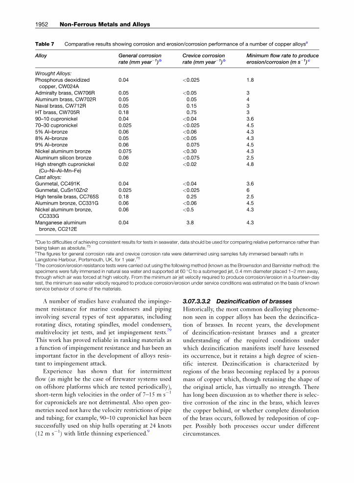
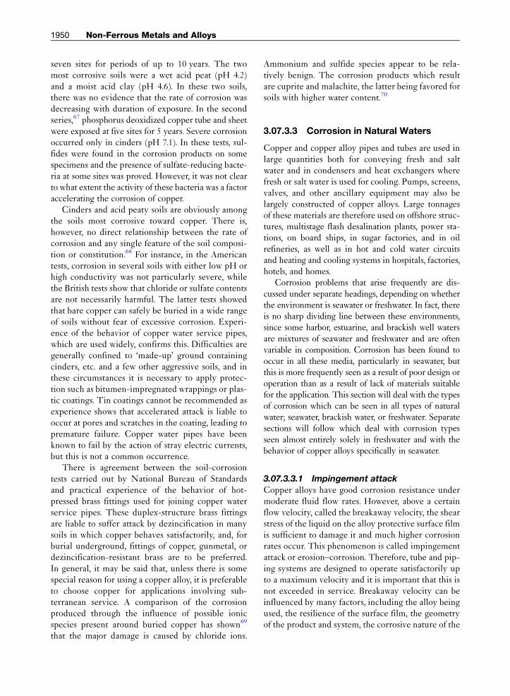
Table 7 Comparative results showing corrosion and erosion/corrosion performance of a number of copper alloysa
Alloy General corrosionrate (mm year�1) b
Crevice corrosionrate (mm year�1) b
Minimum flow rate to produceerosion/corrosion (m s�1) c
Wrought Alloys:
Phosphorus deoxidizedcopper, CW024A
0.04 <0.025 1.8
Admiralty brass, CW706R 0.05 <0.05 3
Aluminum brass, CW702R 0.05 0.05 4Naval brass, CW712R 0.05 0.15 3
HT brass, CW705R 0.18 0.75 3
90–10 cupronickel 0.04 <0.04 3.6
70–30 cupronickel 0.025 <0.025 4.55% Al–bronze 0.06 <0.06 4.3
8% Al–bronze 0.05 <0.05 4.3
9% Al–bronze 0.06 0.075 4.5
Nickel aluminum bronze 0.075 <0.30 4.3Aluminum silicon bronze 0.06 <0.075 2.5
High strength cupronickel
(Cu–Ni–Al–Mn–Fe)
0.02 <0.02 4.8
Cast alloys:
Gunmetal, CC491K 0.04 <0.04 3.6
Gunmetal, CuSn10Zn2 0.025 <0.025 6
High tensile brass, CC765S 0.18 0.25 2.5Aluminum bronze, CC331G 0.06 <0.06 4.5
Nickel aluminum bronze,
CC333G
0.06 <0.5 4.3
Manganese aluminumbronze, CC212E
0.04 3.8 4.3
aDue to difficulties of achieving consistent results for tests in seawater, data should be used for comparing relative performance rather thanbeing taken as absolute.75bThe figures for general corrosion rate and crevice corrosion rate were determined using samples fully immersed beneath rafts inLangstone Harbour, Portsmouth, UK, for 1 year.75cThe corrosion/erosion resistance tests were carried out using the following method (known as the Brownsdon and Bannister method): thespecimens were fully immersed in natural sea water and supported at 60 �C to a submerged jet, 0.4 mm diameter placed 1–2 mm away,through which air was forced at high velocity. From the minimum air jet velocity required to produce corrosion/erosion in a fourteen-daytest, the minimum sea water velocity required to produce corrosion/erosion under service conditions was estimated on the basis of knownservice behavior of some of the materials.
1952 Non-Ferrous Metals and Alloys
A number of studies have evaluated the impinge-ment resistance for marine condensers and pipinginvolving several types of test apparatus, includingrotating discs, rotating spindles, model condensers,multivelocity jet tests, and jet impingement tests.79
This work has proved reliable in ranking materials asa function of impingement resistance and has been animportant factor in the development of alloys resis-tant to impingement attack.
Experience has shown that for intermittentflow (as might be the case of firewater systems usedon offshore platforms which are tested periodically),short-term high velocities in the order of 7–15 m s�1
for cupronickels are not detrimental. Also open geo-metries need not have the velocity restrictions of pipeand tubing; for example, 90–10 cupronickel has beensuccessfully used on ship hulls operating at 24 knots(12 m s�1) with little thinning experienced.9
3.07.3.3.2 Dezincification of brassesHistorically, the most common dealloying phenome-non seen in copper alloys has been the dezincifica-tion of brasses. In recent years, the developmentof dezincification-resistant brasses and a greaterunderstanding of the required conditions underwhich dezincification manifests itself have lessenedits occurrence, but it retains a high degree of scien-tific interest. Dezincification is characterized byregions of the brass becoming replaced by a porousmass of copper which, though retaining the shape ofthe original article, has virtually no strength. Therehas long been discussion as to whether there is selec-tive corrosion of the zinc in the brass, which leavesthe copper behind, or whether complete dissolutionof the brass occurs, followed by redeposition of cop-per. Possibly both processes occur under differentcircumstances.

Corrosion of Copper and its Alloys 1953
The mechanism of dezincification of brass hasbeen investigated and discussed by Evans,80 Fink,80
Lucey,81 Feller,82 and Heidersbach,83 and is referredto in many other papers.84–92 Recent extensive stud-ies93,94 which have investigated the distribution ofcopper isotopes and the effects of specimen rotationduring testing, show that redeposition of copper is amajor mechanism.
With a single-phase brass, the whole of themetal in the corroded areas is affected. Dezincifica-tion may proceed fairly uniformly over the surface,and this ‘layer type’ takes much longer to causeperforation than the more localized ‘plug type’which more often occurs.95 With a two-phase brass,the zinc-rich b phase is preferentially attacked andeventually the a phase may be attacked as well. Thezinc corrosion products which accompany dezincifi-cation may be swept away, or, in some conditions,may form voluminous deposits on the surface.These may in turn lead to blockages, for example,in fittings. In general, the rate of dezincificationincreases as the zinc content rises, and great careneeds to be exercised in making brazed joints withcopper/zinc brazing alloys, particularly if they are tobe exposed to seawater. Under these conditions, aproperly designed capillary joint may last for sometime, but it is preferable to use corrosion-resistantjointing alloys such as silver solders96, as specified inBS EN 1044:1999.
Factors which cause increased rates of dezincifica-tion are high temperature, high chloride content ofwater, and low water speed.97–100 Dezincification isalso likely to occur preferentially beneath deposits ofsand or silt on the metal surface, or in crevices wherethere is a low degree of aeration.
Addition of �0.04% arsenic will inhibit dezin-cification of a brasses in most circumstances andarsenical a brasses can be considered to be immuneto dezincification for most practical purposes.101
There are conditions of exposure in which dezincifi-cation of these materials has been observed, forexample, when exposed outdoors well away fromthe sea37 or when immersed in pure water at hightemperature and pressure, but instances are rare. Inother conditions, for example, in polluted seawater,corrosion can occur with copper redeposition awayfrom the site of initial attack, but this is not trulydezincification, which, by definition, requires themetallic copper to be produced in situ. The work ofLucey81 goes far in explaining the mechanism bywhich arsenic prevents dezincification in a brasses
but not in a–b brasses. An interesting observation isthat the presence of a small impurity content ofmagnesium will prevent arsenic in a brass from hav-ing its usual inhibiting effect.102
The addition of antimony or phosphorus, inamounts similar to arsenic, are claimed to be alsocapable of preventing dezincification of a brasses.However, most manufacturers use arsenic. It appearsdesirable to avoid using phosphorus, as Bem103 hasshown that this element can, in some circumstances,lead to an undesirable susceptibility to intergranularcorrosion. The same can be true for arsenic additionsover �0.05%.
A dezincification resistant alloy, CW602N, wasfirst introduced in 1980. This alloy is a leaded brasswith a zinc content sufficiently high to permit hotforging and extrusion in the b range without crack-ing. After hot working, a heat treatment of up to 6 h at500 �C followed by slow cooling transforms anyresidual b phase to a so that the finished componentis essentially a brass. Dezincification is inhibited byadding arsenic (0.02–0.15%) which protects thea phase, and good machinability is assured by addinglead (1.7–2.8%). The impurities iron and manganese,which combine with arsenic, must be carefully con-trolled for the arsenic to be effective. A rule of thumbis that the percentage of arsenic must be greater thanthe combined percentage of iron and manganese toprovide resistance to dezincification. There is practi-cal evidence that the maximum limits for iron andmanganese allowed in the specification (0.1% each)are too high as, at these levels, the arsenic may berendered ineffective.
Newer studies of intergranular corrosion attack(IGA) of arsenic-containing dezincification resistantbrass93,104 show that there is a close relationship withthe degree of precipitation of iron–arsenic com-pounds in the grain boundaries. The precipitates areformed during low temperature heat treatment orslow cooling after hot forging or a prior heat treat-ment. Sulfide corrosion and dezincification in thegrain boundary appear to be the result as the arsenicis bound to impurities like iron. IGA has also beenreported for aluminum brass (CW 702R) and Mazzaand Torchio105 have presented a laboratory testmethod to reveal IGA in this material. The methodhas also been used successfully for dezincificationresistant brass104 and correlation with field tests inseawater is good.
The addition of 1% tin can markedly reduce therate of dezincification in two phase brasses, and naval
1954 Non-Ferrous Metals and Alloys
brass (61Cu–38Zn–1Sn) is attacked considerablymore slowly than 60/40 brass in seawater, althoughthere may be virtually no difference between them inmost freshwaters. Some of the cast complex high-strength two-phase brasses containing tin, aluminum,iron, and manganese appear to have relatively goodresistance to dezincification, but they are by nomeans immune to it.
Dezincification of brasses in drinking water mayoccur, particularly in stagnant or slowly-movingwarm or hot waters relatively high in chloride andcontaining little carbonate hardness.106 Dezincifica-tion of a brasses is inhibited by the usual arsenicaddition, but two-phase brasses are liable to severeattack in some waters. In such cases, dezincification-resistant brass or gunmetal fittings should be used. Ifcopper/zinc brazing alloys are used, these may dezin-cify in water known to support this type of corrosionand may consequently give rise to leaks.106
3.07.3.3.3 Selective attack in other alloys
Selective attack analogous to dezincification canoccur in other copper alloys, particularly in alumi-num bronzes and, less frequently, in tin bronzes,107
cupronickels,108 and other alloys. Dealuminificationof aluminum bronzes has been studied extensively109
and the results indicate that, while a-phase alloyssuffer such attack comparatively rarely, alloys ofhigher aluminum content can be more susceptible.The electrochemical relationships are such that pref-erential corrosion of the second phase is liable to occurin a–g2 alloys, but a–b alloys are relatively resistant toattack. Retention of b phase is favored by rapid coolingafter casting or after high temperature heat treatment,and also by incorporating manganese in the alloy.A tempering heat treatment in the temperature rangeof 650–740 �C has been found to hinder the occur-rence of dealuminification due to the transformationof the more corrosion-prone b phase to a combinationof a phase and comparatively benign k phases.110
The addition of nickel to aluminum bronze hasbeen found useful in controlling the occurrence ofthe g2 phase, which has a corrosion potential�100 mV less noble than the a phase, thereby under-going selective attack in seawater. Weill-Couly andArnauld111 have determined an empirical relationship,eqn [6] shown below, which denotes the aluminumcontent of nickel–aluminum bronze castings belowwhich a resistance to dealuminification is found.
Al � 8:2þNi
2½6�
3.07.3.3.4 Deposit attack and pittingWhen water speeds are low and deposits settle on thesurface, pitting in copper and copper alloys is liable tooccur by differential aeration effects. This is particu-larly so at water speeds below �1 m s�1. In seawatersystems, such attack may occur under dead barnaclesor shellfish, the decomposing organic matter assistingthe corrosion process. Pitting is most likely to occur inpolluted in-shore waters, particularly when hydrogensulfide is present. In such contaminated waters, non-protective sulfide scales are formed and these tend tostimulate attack. It has been found possible to developa mathematical model which can be successfully usedto calculate the electrode potential below which cop-per is immune to pitting in tap water or seawater in thetemperature range 25–75 �C.112 Of the 26 ionic spe-cies which have been included in the calculation,CO3
2� and SO42� were found to be the most aggressive.
3.07.3.4 Corrosion in Freshwater
Freshwaters are, in general, less corrosive towardcopper than is seawater and copper is widely andsatisfactorily used for distributing cold and hot watersin domestic and industrial installations.113–116 Cop-per and copper alloys are used for pipes, hot-watercylinders, ball valves, taps, fittings and heater sheaths.In condensers and heat exchangers using freshwaterfor cooling, tubes of 70/30 brass or Admiralty brassare usually used, and corrosion is rarely a problem.Nevertheless, the widespread use of copper and cop-per alloys since the early part of last century espe-cially in domestic water systems has meant that alladverse situations have been experienced and thefollowing are rare but notable corrosion issues. TwoBritish Standards give guidance on the likelihood ofcorrosion in water distribution and storage systemsand in water recirculating systems. These are BSEN12502:2004 and BSEN14868:2005.
3.07.3.4.1 Pitting
Occasionally copper water pipes fail prematurely bypitting. This a general term and is used for any failureof the pipework system leading to a leak. Pittingcorrosion of copper in drinking water systems isoften categorized as Type I, II, or III but othertypes of localized corrosion are also known. However,there may be no strict limits between Type I andType II pits; in relatively saline tap waters, corrosionpits showing traits of both types have been found.Only through proper investigation can the cause ofpitting be identified, such as in the following sections.

Corrosion of Copper and its Alloys 1955
3.07.3.4.1.1 Carbon film pitting
Carbon film pitting, also known as ‘Type I’ pitting,has been a frequent problem. An example of this in acopper tube from a domestic water supply is shownin Figure 3 with the corrosion products removedfrom the main pit. The characteristics of the pits arehemispherical cavities with large crusts of corrosionproducts outside. The composition of the crusts ismainly basic cupric carbonates for example, mala-chite. Cuprous chloride and reddish cuprous oxidecrystals may be found inside the cavity. The presenceof CaCO3 in the crust outside the cavity led Lucey
117
to propose a particular mechanism for this type ofpitting. Contrary to conventional descriptions of thepitting processes, Lucey postulated that the cathodicreaction that is, the oxygen reduction, takes place atthe crust of corrosion products which cover the cav-ity. The phenomenon was found to occur in organi-cally pure, cold waters originating from deep wellsand boreholes and was shown by Campbell118 to beassociated with residual films of carbon on the bore ofthe tubes. This carbon was caused by decompositionof residual drawing lubricant during bright (reducingatmosphere) annealing. It is therefore necessary formanufacturers to take steps to avoid these harm-ful residues. This type of pitting attack has beenidentified in many different countries119 and may beassisted by iron-rich precipitates which can be pres-ent at the grain boundaries.120,121 There is evidencethat it could be inhibited by the presence of organicspecies in the water.122
This evidence has been corroborated in the UnitedKingdom by Campbell, who found failures due to thiseffect were confined to certain districts that is, supplywaters. He showed that for many supply waters this
Figure 3 Photograph showing carbon film pitting on a
copper tube.
pitting cannot proceed even in tubes containing car-bonaceous cathodic films. He proposed that this ismost probably due to the presence of small amountsof a naturally-occurring inhibitor in the water, proba-bly an organic colloidal material, which stifles pittingof copper. Pipe failures therefore only occur in waterswhich contain little or none of this inhibitor.
Pitting problems also occasionally occur in copperwater cylinders123 and, as a result of a study of this pro-blem, Lucey117 has made suggestions about the mech-anism of pitting of copper in potable water supplies.Several suggested methods of avoiding pitting failuresin copper cold-water tubes have been evaluated.124–126
3.07.3.4.1.2 Hot soft water pitting and Type II
pitting
In hot water pipes, failures sometimes occur in cer-tain areas supplied with soft waters from moorlandgathering grounds. The waters concerned contain afew hundredths of a part per million of manganese,and in the course of several years’ exposure, a depositrich in manganese dioxide is laid down in the hottestparts of the system. This may cause pitting whichcould eventually lead to failure.
Hot-water pitting of another type, often referredto as ‘Type II’ pitting, is sometimes experienced insoft waters having high sulfate content in relationto the carbonate hardness and a relatively low pHvalue and it has been described by Mattson andFredriksson.127 The crusts covering these pits areless voluminous than Type I pits, the cavities arebranching and they may be almost completely filledwith black cuprous oxide. The occurrence of Type IIpitting is associated with waters with pH � 7 and lowcarbonate contents. A successful remedy has been toincrease pH, introduce carbonate dosing to give aminimum of 70 mg HCO3
� per liter, or reduce thewater temperature to less than 60 �C.
3.07.3.4.1.3 Type III pitting
This type of pitting occurs in cold soft waters with apH above 8.0 and it is geographically localized, beingmainly confined to Sweden. It is generalized form ofpitting where the pits are sparse128,129. Mattson128
describes the phenomenon, noting its morphologyand means of avoidance through a method involvingbicarbonate dosing of the drinking water.
3.07.3.4.1.4 Electrochemistry of pitting
Drogowska et al.130 have used solutions designed tomimic natural waters containing bicarbonate andchloride ions to study the anodic oxidation of copperand onset of pitting corrosion. They have found that,

1956 Non-Ferrous Metals and Alloys
as the anodic polarization of copper increases in thisenvironment, a porous layer of Cu2O initially formson the metal surface. This is found to convert to basicCuCO3 at more positive anodic potentials or in higherconcentrations of HCO3
� ions. A passivity breakdownpotential is recorded at which pitting initiates, and thisbecomes more positive when HCO3
� ions are present.The presence of Cl� ions shifts the pitting potential tolower values, but the HCO3
� ions are found to act toprevent this effect. Sulfate ions are found to have a verysimilar effect to chloride ions in lowering the break-down potential131 and pitting is found to be avoidedif the pH � 7.4 and the [HCO3
�]/[SO42�] ratio is �1.
The effect of increasing the solution temperatureto 60 �C is found to give improvement to the passivityof the oxide film.132 Two new international standardshave been produced which give guidance on cor-rosion prevention in water distribution and storagesystems.133
3.07.3.4.2 Chemical attack
Joining copper should be accomplished according torecommended practice to avoid corrosion issues.Copper pipework installations are joined using capil-lary attraction of solder or braze material or bymechanical means.
In the case of capillary joints, fittings, or in somecases specifically formed tube ends, are used to forman annular capillary gap into which molten solder orbraze is run. Fluxes containing chlorides have to beused when soldering. The chlorides act to removesurface oxide and reduce the surface tension, allow-ing the solder to be drawn into the capillary gap.Excessive use of flux can lead to its retention inthe pipework and attack by the chloride ions present.
Soldering Flu
Figure 4 Photograph showing flux attack on a soldered copp
This will normally take place in the first few monthsafter installation. An example of this is shown in Fig-ure 4. Over longer periods when the active elementsof the flux are exhausted, the presence of residue canlead to deposit attack. In both of these cases, pittingcorrosion and failure of the tube can result. Goodinstallation practice which ensures complete removelof any flux residue by washing (as given by BS6700:1997) will prevent this type of corrosion. Capil-lary joints formed using copper/phosphorus, copper/silver/phosphorus, or silver brazing alloys do not needflux and therefore cannot suffer this type of attack.
3.07.3.4.3 Microbiologically influenced
corrosion
Microbiologically influenced corrosion (MIC),describes a form of pitting considered to be due tothe action of microbes. This form of corrosion of metalshas been known for many years, for instance in the oilindustry, and an early description of its occurrencewith copper alloys was given by Rogers in 1948.134 Insome instances, MIC has been associated with softwater which is high in organic content which hasbeen allowed to maintain temperatures in the regionof 20–30 �C under low velocity conditions. In suchcircumstances, the resulting warm high concentrationof organic material at the bottom of horizontal tubesprovides ideal conditions for MIC to take place.135
Other circumstances with a different water qualityhave been described by Wagner et al.136 However, theexact MIC mechanism has not been elaborated. Thegeneral view is that a region of low pH is created undera biofilm containing polysaccharides and that theorganic materials present provide transport for themetal ions to the liquid phase.137
x run-off and leak
Typical protectivecorrosion layer
er tube.
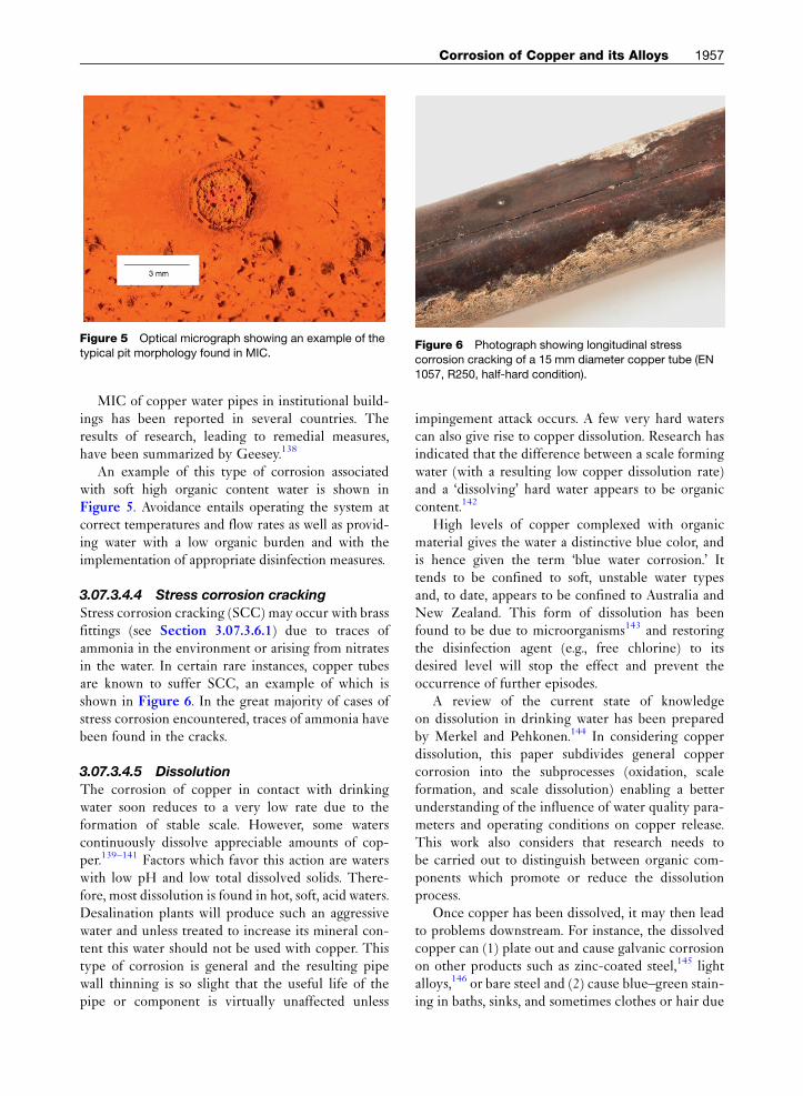
Figure 5 Optical micrograph showing an example of thetypical pit morphology found in MIC.
Figure 6 Photograph showing longitudinal stresscorrosion cracking of a 15 mm diameter copper tube (EN
1057, R250, half-hard condition).
Corrosion of Copper and its Alloys 1957
MIC of copper water pipes in institutional build-ings has been reported in several countries. Theresults of research, leading to remedial measures,have been summarized by Geesey.138
An example of this type of corrosion associatedwith soft high organic content water is shown inFigure 5. Avoidance entails operating the system atcorrect temperatures and flow rates as well as provid-ing water with a low organic burden and with theimplementation of appropriate disinfection measures.
3.07.3.4.4 Stress corrosion cracking
Stress corrosion cracking (SCC) may occur with brassfittings (see Section 3.07.3.6.1) due to traces ofammonia in the environment or arising from nitratesin the water. In certain rare instances, copper tubesare known to suffer SCC, an example of which isshown in Figure 6. In the great majority of cases ofstress corrosion encountered, traces of ammonia havebeen found in the cracks.
3.07.3.4.5 Dissolution
The corrosion of copper in contact with drinkingwater soon reduces to a very low rate due to theformation of stable scale. However, some waterscontinuously dissolve appreciable amounts of cop-per.139–141 Factors which favor this action are waterswith low pH and low total dissolved solids. There-fore, most dissolution is found in hot, soft, acid waters.Desalination plants will produce such an aggressivewater and unless treated to increase its mineral con-tent this water should not be used with copper. Thistype of corrosion is general and the resulting pipewall thinning is so slight that the useful life of thepipe or component is virtually unaffected unless
impingement attack occurs. A few very hard waterscan also give rise to copper dissolution. Research hasindicated that the difference between a scale formingwater (with a resulting low copper dissolution rate)and a ‘dissolving’ hard water appears to be organiccontent.142
High levels of copper complexed with organicmaterial gives the water a distinctive blue color, andis hence given the term ‘blue water corrosion.’ Ittends to be confined to soft, unstable water typesand, to date, appears to be confined to Australia andNew Zealand. This form of dissolution has beenfound to be due to microorganisms143 and restoringthe disinfection agent (e.g., free chlorine) to itsdesired level will stop the effect and prevent theoccurrence of further episodes.
A review of the current state of knowledgeon dissolution in drinking water has been preparedby Merkel and Pehkonen.144 In considering copperdissolution, this paper subdivides general coppercorrosion into the subprocesses (oxidation, scaleformation, and scale dissolution) enabling a betterunderstanding of the influence of water quality para-meters and operating conditions on copper release.This work also considers that research needs tobe carried out to distinguish between organic com-ponents which promote or reduce the dissolutionprocess.
Once copper has been dissolved, it may then leadto problems downstream. For instance, the dissolvedcopper can (1) plate out and cause galvanic corrosionon other products such as zinc-coated steel,145 lightalloys,146 or bare steel and (2) cause blue–green stain-ing in baths, sinks, and sometimes clothes or hair due
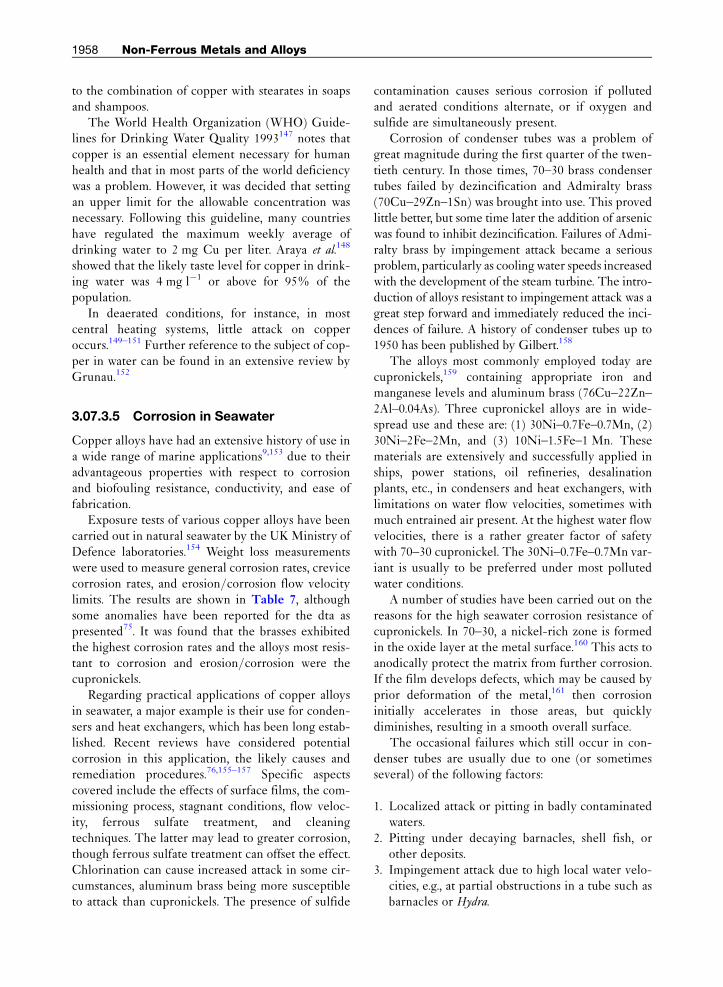
1958 Non-Ferrous Metals and Alloys
to the combination of copper with stearates in soapsand shampoos.
The World Health Organization (WHO) Guide-lines for Drinking Water Quality 1993147 notes thatcopper is an essential element necessary for humanhealth and that in most parts of the world deficiencywas a problem. However, it was decided that settingan upper limit for the allowable concentration wasnecessary. Following this guideline, many countrieshave regulated the maximum weekly average ofdrinking water to 2 mg Cu per liter. Araya et al.148
showed that the likely taste level for copper in drink-ing water was 4 mg l�1 or above for 95% of thepopulation.
In deaerated conditions, for instance, in mostcentral heating systems, little attack on copperoccurs.149–151 Further reference to the subject of cop-per in water can be found in an extensive review byGrunau.152
3.07.3.5 Corrosion in Seawater
Copper alloys have had an extensive history of use ina wide range of marine applications9,153 due to theiradvantageous properties with respect to corrosionand biofouling resistance, conductivity, and ease offabrication.
Exposure tests of various copper alloys have beencarried out in natural seawater by the UK Ministry ofDefence laboratories.154 Weight loss measurementswere used to measure general corrosion rates, crevicecorrosion rates, and erosion/corrosion flow velocitylimits. The results are shown in Table 7, althoughsome anomalies have been reported for the dta aspresented75. It was found that the brasses exhibitedthe highest corrosion rates and the alloys most resis-tant to corrosion and erosion/corrosion were thecupronickels.
Regarding practical applications of copper alloysin seawater, a major example is their use for conden-sers and heat exchangers, which has been long estab-lished. Recent reviews have considered potentialcorrosion in this application, the likely causes andremediation procedures.76,155–157 Specific aspectscovered include the effects of surface films, the com-missioning process, stagnant conditions, flow veloc-ity, ferrous sulfate treatment, and cleaningtechniques. The latter may lead to greater corrosion,though ferrous sulfate treatment can offset the effect.Chlorination can cause increased attack in some cir-cumstances, aluminum brass being more susceptibleto attack than cupronickels. The presence of sulfide
contamination causes serious corrosion if pollutedand aerated conditions alternate, or if oxygen andsulfide are simultaneously present.
Corrosion of condenser tubes was a problem ofgreat magnitude during the first quarter of the twen-tieth century. In those times, 70–30 brass condensertubes failed by dezincification and Admiralty brass(70Cu–29Zn–1Sn) was brought into use. This provedlittle better, but some time later the addition of arsenicwas found to inhibit dezincification. Failures of Admi-ralty brass by impingement attack became a seriousproblem, particularly as coolingwater speeds increasedwith the development of the steam turbine. The intro-duction of alloys resistant to impingement attack was agreat step forward and immediately reduced the inci-dences of failure. A history of condenser tubes up to1950 has been published by Gilbert.158
The alloys most commonly employed today arecupronickels,159 containing appropriate iron andmanganese levels and aluminum brass (76Cu–22Zn–2Al–0.04As). Three cupronickel alloys are in wide-spread use and these are: (1) 30Ni–0.7Fe–0.7Mn, (2)30Ni–2Fe–2Mn, and (3) 10Ni–1.5Fe–1 Mn. Thesematerials are extensively and successfully applied inships, power stations, oil refineries, desalinationplants, etc., in condensers and heat exchangers, withlimitations on water flow velocities, sometimes withmuch entrained air present. At the highest water flowvelocities, there is a rather greater factor of safetywith 70–30 cupronickel. The 30Ni–0.7Fe–0.7Mn var-iant is usually to be preferred under most pollutedwater conditions.
A number of studies have been carried out on thereasons for the high seawater corrosion resistance ofcupronickels. In 70–30, a nickel-rich zone is formedin the oxide layer at the metal surface.160 This acts toanodically protect the matrix from further corrosion.If the film develops defects, which may be caused byprior deformation of the metal,161 then corrosioninitially accelerates in those areas, but quicklydiminishes, resulting in a smooth overall surface.
The occasional failures which still occur in con-denser tubes are usually due to one (or sometimesseveral) of the following factors:
1. Localized attack or pitting in badly contaminatedwaters.
2. Pitting under decaying barnacles, shell fish, orother deposits.
3. Impingement attack due to high local water velo-cities, e.g., at partial obstructions in a tube such asbarnacles or Hydra.
Corrosion of Copper and its Alloys 1959
4. Erosion due to sand or other abrasive particlessuspended in the water.
5. Use of tubes of the wrong alloy, or of incorrectcomposition or which contain manufacturingdefects.
6. Poor welding techniques causing welds to pro-trude into the flow.
The material most commonly used when suspendedabrasive matter is a problem is the 30% Ni alloycontaining 2% each of Fe and Mn.156,157
A difficult condenser-tube corrosion problemarises from the use of polluted cooling waters fromharbors and estuaries, which may be severely con-taminated, particularly when warmer climates areinvolved.162 Many condenser-tube materials are lia-ble to suffer corrosion in these circumstances, and thechoice of materials is made difficult by the fact thatdifferent orders of merit apply at different locationsand even at the same location at different times. Thestate of the water when the tubes are commissionedand first enter service, which influences the type ofsurface film formed, may well determine whether ornot a satisfactory service life will be obtained.159,163
Full salinity seawater, free from sulfides, is reportedto be the most effective passivating medium162
although the 14–60 days which this takes to completemay put it at a lower ranking than other methods,particularly those involving dosing with ferroussulfate76.
In power plants, the condenser tubes must be ableto withstand corrosive cooling waters and complexboiler water treatments. Also, the use of recirculatingwater can cause dissolved salts to concentrate betweentwice and eight times the initial concentration, makingthewater significantlymore aggressive.164 Corrosion ofpower-station condenser tubes by polluted waterswas at one time particularly troublesome in Japan.Improved results have been reported using tin brassesor special tin bronzes.165 Elsewhere, pretreatmentshave been investigated with mixed success76,166 andsodium dimethyldithiocarbamate is reported to giveprotective films which will withstand the action ofpolluted waters167 and has had some naval use.76
Methods of maintaining tube cleanliness includechlorination and mechanical methods such as waterlancing and the use of the Taprogge system of circu-lating sponge-rubber balls.157 Hot acid is now notenvironmentally acceptable and the use of commer-cial descaling agents invariably results in the nearcomplete loss of the passive surface layers on thematerial.168 Thus, it is recommended that, after
their use, a period of 3 weeks or more should beimposed during which natural seawater is allowed toflow through the system to restore passivity.
Condenser tube-plates of naval brass usuallyundergo some dezincification in seawater service,but this is normally not serious in view of the thick-ness of the metal involved. Use has been made oftube-plates of more resistant materials such as alumi-num bronze, or cupronickel. Plates that are too largeto be rolled in one piece can be fabricated by weldingtogether two or more items. In some special applica-tions, the tubes are fusion welded or explosivelywelded to the tube plates. Fusion welding operationsare rather more difficult with brasses than with othercopper alloys due to the evolution of zinc fumeduring the process.
Condenser water-boxes were at one time made ofunprotected (or poorly protected) cast iron and theseafforded a measure of cathodic protection to the tubeplates and tube ends. This beneficial effect has beenlost with the general adoption of water-boxes whichare completely coated with rubber or some otherimpervious layer, or which are made from resistantmaterials such as gunmetal, aluminum–bronze, orcupronickel. Steel water-boxes which are clad withcupronickel are also used. To prevent attack on tube-plates and tube-ends in these circumstances, either asuitable applied-current cathodic protection systemcan be applied or sacrificial soft-iron or mild-steelanodes can be installed, the required protection volt-age being fairly low (50 mV minimum).169 Ferrouswastage plates have the additional advantage that theiron corrosion products introduced into the coolingwater assist in the development of good protectivefilms throughout the length of the tubes. This isparticularly important in the case of aluminum–brass tubes; indeed, with such tubes it may be desir-able, as an additional preventative measure, to add asuitable soluble iron salt (such as ferrous sulfate)regularly to the cooling water.
As it has become increasingly necessary to supple-ment natural sources of freshwater in various parts ofthe world, processes for producing freshwater fromseawater have been intensively studied. Distillation isone method widely used and, during recent years,large numbers of multistage flash-distillation plantshave been installed in various countries particularlyin theMiddle East. Many of the larger flash-distillationunits are capable of producing several millions ofgallons of freshwater per day. In these plants, seawaterpasses through horizontally disposed tubes andsteam, which is ‘flashed’ from the brine, condenses

1960 Non-Ferrous Metals and Alloys
on the outside. In some parts of the plant, the condi-tions are similar to those in steam condensers, but inother parts the seawater has been treated to removedissolved gases and is at much higher temperatures.Copper alloy tubes are used in large numbers for theheat exchange units in this type of desalinationplant,170,171 these being mainly aluminum–brass andthe various cupronickel alloys.
For cooling-water trunking and saltwater servicesin the engine room and elsewhere, including firemains, plumbing, and air-conditioning systems inships, more resistant alloys are taking the place ofcopper or galvanized steel. The latter were formerlyextensively employed, but they do not have adequateresistance to attack by seawater. Cu–10Ni–1.5Fe alloyhas been widely utilized and normally gives excellentservice. In some special naval applications, pipelinesof 70–30 cupronickel are used and it has been foundthat adequate attention must be given to correctfabrication and installation techniques. Carbonaceousresidues from fillers used in bending operations mustbe avoided or pitting corrosion may occur in service.Jointing materials of low corrosion resistance shouldnot be used, silver brazing or appropriate weldingmethods being the correct techniques. Residual stres-ses, if present, can cause stress-corrosion failures ofaluminum–brass pipelines in service.
Copper alloys inwrought or cast form are employedfor other purposes in ships and marine installations,such as for propellers, bearings, valves, and pumps. Forinstance, aluminum–brass is used for heating coils intankers carrying crude oil or petroleum products.However, some corrosion problems encountered inthis and other applications on board ship have beendescribed by Gilbert and Jenner.172
Cupronickels have been shown to possess ex-tremely low long-term corrosion rates in quiet orslowly-moving seawater. The 90–10 alloy is of partic-ular interest28,163: this alloy is now well establishedfor use for pipelines on ships and it has becomewidely used for piping systems on floating produc-tion, storage and offloading vessels (FPSO’s), andoffshore platforms. In addition to its good corrosionresistance, 90–10 cupronickel has a high resistance tomarine macrofouling providing that it is not cathodi-cally protected. This has led to applications such asthe construction or sheathing of ships’ hulls, fishcages for aquaculture and cladding of steel offshorestructures in the tidal/splash zones.9
Investigations into the effects of arsenic and phos-phorus in single phase brasses on their susceptibilityto intergranular attack and SCC in seawater have
shown that the normal additions of arsenic to inhibitdezincification (�0.04%) have no significant adverseeffect. Other possible consequences of exposing cop-per alloys to seawater which have been investigatedincluded dealloying of aluminum bronzes109 and theeffects at bimetallic contacts.
Major efforts have been made to understand thenature of films formed on copper alloys in naturalseawater. These films have quite different character-istics to those formed in sodium chloride solution, thedifferences being associated with the presence oforganic material in the natural environment. However,the structure of the films is affected by variables suchas water velocity, temperature, and oxygen content.Protective films often have a multilayered structure,157
with an outer layer rich in iron providing impinge-ment resistance and an inner layer giving chemical/electrochemical protection. With aluminum brass,a colloidal mixed hydroxide inner layer provides abuffering action, with tin-containing brass thereis a tin-rich layer near the copper surface173 and,with cupronickel, there is a chloride-rich layer whichstrongly inhibits the cathodic reaction. A study on Cu–Si alloys in seawater has found that the formation ofcopper silicide at the alloy surface acts to preventcorrosion.174
3.07.3.6 Effect of Exposure toContaminated Environments
As with many metallic materials, failure of copperalloys may occur by cracking due to the combinedinfluence of tensile stress and exposure to a debilitat-ing environment due to the presence of a contami-nant. Failures of brass components due to this form ofstress corrosion cracking have been known for manyyears175 and has been termed season cracking. In thiscase, the stresses in the material are producedin components during their manufacture and thecontaminant is ammonia vapor produced by the nat-ural decay of organic matter.
Only certain specific environments appear to pro-duce stress corrosion of copper alloys, most notablyammonia,176–178 ammonium compounds, or amines.Interestingly, pure copper does not suffer fromammonia-induced stress corrosion but will displaythe phenomenon in the presence of nitrites.179 Stresscorrosion can also occur with moist sulfur dioxide,sulfites, and some organic acids.180 Mercury orsolutions of mercury salts (which cause depositionof mercury), or other molten metals will alsocause cracking, but the mechanism is undoubtedly
Corrosion of Copper and its Alloys 1961
different.181 Cracks produced by mercury are alwaysintergranular, but ammonia, according to the exactconditions, may produce cracks which are fully trans-granular, fully intergranular, or a mixture of both. Asan illustration of this, Edmunds182 found that mer-cury would not produce cracking in a stressed singlecrystal of brass, whereas ammonia could do so.
In certain circumstances, corrosion of copperalloys can occur through seemingly randominterconnected microtunnels which spread out intothe metal from what appears to be only a discolor-ation of the surface film. As a result of this phenom-enon, through-thickness perforation of tube canresult in weeks or months. This type of corrosionhas been termed formicary corrosion due to its mor-phological similarity to an ants nest. Elliott183 hasproduced a summary of knowledge of formicary cor-rosion up to 1999. The cause has been ascribed tocontamination of the outside of the tube by carbox-ylic acids.
3.07.3.6.1 Stress corrosion of brasses
Brasses containing only a few percent of zinc maycrack under load if the stresses are high and theenvironment is sufficiently corrosive and most typesof brass appear to be susceptible to the occurrence ofthis phenomenon of stress corrosion. An investigationof the effect of additions to 70–30 brass has beencarried out by Wilson et al.,184 who found that anaddition of �1% Si was markedly beneficial. Otheradditions were beneficial under some circumstancesbut none of the 36 additions tested accelerated stress-corrosion cracking. Further results have been givenin later papers.185,186
In general, the susceptibility to stress corrosion inbrasses appears to rise with an increase of zinc con-tent, but in some circumstances alloys containing64–65% Cu were found to be rather more affectedthan those containing 60% Cu.187
Many workers188–193 have investigated the resid-ual stresses introduced by different working pro-cesses in brasses of various compositions and theannealing treatments necessary to remove thesestresses or reduce them to a safe level. A ‘stress-reliefanneal’ at �300 �C will usually lower internal stres-ses to comparatively small values without mucheffect on hardness of the material.
Specifications for brass products customarilyinclude the provision for carrying out a mercurousnitrate test194,195 (EN ISO 196:1995) to ensurethat unduly high residual tensile stresses are notpresent, but a satisfactory result in this test does not
guarantee freedom from cracking in environmentscontaining ammonia. More searching tests involvingexposure to ammonia have therefore been devised,such as ISO 6957:1988. The standardization of stress-corrosion cracking tests and their correlation withservice experience have been the subject of severalpapers.196–200 A European standard for the assessmentof susceptibility to SCC was published in 2006: EN14977, Copper and copper alloys – detection of tensilestress – 5% ammonia test. Many authors201–205 havedescribed practical cases of stress-corrosion crack-ing usually involving tensile stresses applied in ser-vice. Two possible preventive measures are the use ofcoatings206–208 or inhibitors.209
The behavior of a wide range of a, a–b, and bbrasses in various corrosive environments was studiedby Voce and Bailey and their results have been sum-marized by Whitaker.210 Penetration by mercury andby molten solder was found to be intergranular inall three types of brass. In moist ammoniacal atmo-spheres, the penetration of unstressed brasses of alltypes was intergranular. Internal applied stressesaccelerated the intergranular penetration of a brassesand initiated some transgranular cracking. It alsocaused severe transgranular cracking of b alloysand transgranular cracking across the b regionsin the two-phase brasses. Immersion in ammoniasolution, however, caused intergranular cracking ofstressed b brasses. b brasses containing 3% or morealuminum failed with an intergranular fracture whenstressed at �0.1% proof stress in air. The behaviorof alloys of this type was subsequently studied byPerryman211 and Bailey212 who showed that crackingin air occurs only when moisture is present. It hasbeen confirmed that b brasses are prone to crack inservice.213
High-strength a–b brasses containing up to �5%Al (with small amounts of Fe, Mn, Sn, etc.) used forpropellers, parts of pumps, nuts and bolts, and similarapplications usually give good service but occasion-ally suffer intergranular failure, for instance in con-tact with seawater. Examination of such failuresusually reveals thin dezincified layers along thecracks, but it is often difficult to decide whether thecrack or the dezincification occurred first.
The theoretical aspects of stress-corrosion crack-ing have attracted much attention in recent years.Among the copper alloys, the behavior of brasses inammoniacal environments has been most studied.While cracking has been shown to be possible incontact with some other corrosive agents, ammoniahas the most powerful effect. Evans214 suggests that

1962 Non-Ferrous Metals and Alloys
this is because ammonia is a feeble corrodent whichproduces little attack except at regions such as grainboundaries or other lattice imperfections. Also, itprevents accumulation of copper ions in the crevicesformed owing to the formation of stable complexessuch as Cu[(NH3)4]
2+. The mode of cracking (inter-granular or transgranular) can be affected by changesin composition of the brass or by changes in thenature of the environment.215 Mattsson216 foundthat, on immersion in ammoniacal solutions of differ-ent pH values, stressed brasses cracked most rapidlyat pH 7.1–7.3 and that in this range black surfacefilms formed on the metal. The role of tarnish filmshas been further studied subsequently.217–219 Manyauthors have studied electrochemical220–235 or met-allurgical236–241 aspects of the stress corrosion ofcopper alloys and discussed theories of the mecha-nism. Papers on the subject have been included inseveral symposia or conferences on stress corrosionof metals.242–244 The stress cracking of brasses hasbeen reviewed by Bailey245 and other workers246–254
and reviews of stress corrosion as a general subjecthave also been published.255–257
3.07.3.6.2 Stress corrosion of other copper
alloys
Evidence indicates that pure copper is not likelyto be susceptible to stress corrosion258–260 butinstances of the failure of copper are known, whenit contains 0.4% As261 or 0.02% P.258 SCC hasalso been found to occur in copper–beryllium,262
copper–manganese,263–265 aluminum–bronzes,266,267
tin–bronzes, silicon–bronzes, nickel silvers,268 andcupronickels.268,269 Most of these alloys are muchless susceptible to cracking than brasses,270 althoughunder some conditions aluminum–bronzes can beparticularly prone to cracking.271 In ammoniacalenvironments, the cracking tends to be transgranular,and in steam atmospheres, intergranular cracking isfavored.272 Additions of 0.35% Sn or Ag are claimedto be effective in preventing intergranular crack-ing.273,274 Aluminum–bronzes containing 2% Niand 0.5–0.75% Si are claimed to have good resistanceto stress corrosion,273,275 although there is evidencethat silicon bronzes can show accelerated intergranu-lar fracture in the presence of moist air.
Thompson and Tracy258 carried out tests in amoist ammoniacal atmosphere on stressed binarycopper alloys containing zinc, phosphorus, arsenic,silicon, nickel, or aluminum. All these elements gavealloys susceptibility to stress corrosion. In the case ofzinc, the failure time decreased steadily with increase
of zinc content, but with most other elements therewas a minimum in the curve of concentration of alloy-ing elements against time to failure. In tests carried outunder a static load of 70 MN m�2, these minima werefound to occur at concentration levels of �0.2% P,0.2% As, 1% Si, 5% Ni, and 1% Al. In most cases, thecracking was observed to be intergranular.
A series of slow strain rate tests have been carriedout on high strength Cu–Ni–Al alloys in environ-ments which could be encountered by the offshore oiland gas industry276 and these have found that theapplication of a cathodic potential (as applied incathodic protection) gives protection against stresscorrosion. However, molybdenum disulfide greasesmixed with seawater and greases containing bentonewere found to promote stress corrosion as did themore well known debilitating species such as amines.Work on relating the microstructural aspects of thesealloys to their possible susceptibility to stress corro-sion has identified277 that the production processshould be undertaken in such a way that the presenceof iron-rich phases on the grain boundaries isrestricted, the material has a fine grain size and thatit is supplied in an under-aged condition.
Cupronickels (90–10 and 70–30) have generallybeen considered immune to sulfide stress corrosionin most seawater environments.9 However, there havebeen recent trials278 in seawater containing severesulfide levels of 100–1000 ppm which indicate acracking possibility for the 90–10 alloy.
A related debilitating effect to stress corrosioncracking is hydrogen embrittlement, and it is inter-esting to note that copper alloys have not beenreported to suffer from this phenomenon. In particu-lar, testing has demonstrated that high strength Cu–Ni–Al and Cu–Ni–Sn alloys do not embrittle underhydrogen charging conditions277 whereas nickelalloys containing copper and aluminum (Ni–Cu–Al)lose ductility under the same conditions. Detailedelectrochemical work carried out by Pound279 allowedhim to suggest that this is because the internal hydro-gen becomes associated with both reversible and irre-versible trap sites. He postulates that the trap sites in aCu–Ni–Al alloy are measurably more reversible thanthose in Ni–Cu–Al, preventing the former from beingsusceptible to hydrogen embrittlement.
3.07.3.7 Corrosion in Industrial Chemicals
A number of publications are available which givedetailed information on the action of a wide range ofchemicals on copper and copper alloys.280–285

Corrosion of Copper and its Alloys 1963
When contemplating the use of copper-basedmaterials for industrial purposes it is necessary tobear in mind that, even though a satisfactory life ofthe component may be obtained, possible difficultiesmay arise from the following other causes:
1. Copper compounds can be tolerated only in smallamounts in potable waters or food substances. TheWHO current safe concentration limit for copperin drinking water of 2.0 mg l�1.
2. Copper compounds are highly colored, and a verysmall amount of corrosion may lead to stainingand discoloration of products.
3. Stimulation of the corrosion of vital parts made ofmore anodic metals may occur if they areconnected to copper.
4. Very small amounts of copper taken into solutionmay cause considerable corrosion of more anodicmetals elsewhere in the system, particularlyzinc,145 aluminum,146 and sometimes steel.286
Small particles of copper deposited from solutionset up local cells which can cause rapid pitting.
Despite these qualifications, copper and its alloysare used extensively and successfully in many typesof chemical production equipment. Uses includecondensers and evaporators, pipelines, pumps,fans, vacuum pans, and fractionating columns. Tin–bronzes, aluminum–bronzes, silicon–bronzes, andcupronickels are used in some circumstances becausethey present better corrosion resistance than copperor brasses.
3.07.3.7.1 Acid solutions
Copper does not normally displace hydrogen, evenfrom acid solutions, and it is therefore virtually un-attacked in nonoxidizing conditions. For stronglyreducing conditions in the temperature range 300–400 �C, corrosion resistance is comparable, if notbetter, than stainless steel. However, when copperalloys come into contact with most solutions, whichinvariably contain dissolved air, cathodic depolariza-tion can occur which increases the chances that cor-rosion will take place.287 Therefore, it is difficult to laydown any general recommendations for the use ofcopper in acid solutions, since the rate of attack signifi-cantly depends on the particular circumstances.Under fairly mild conditions copper or copper alloysare successfully used for handling solutions of hydro-fluoric,280,288,289 hydrochloric,280,290 sulfuric,291 phos-phoric,280,292 acetic, and other fatty acids.280,293 Ratesof corrosion, in general, increase with concentration ofacid, temperature, amount of aeration,294,295 and speed
of flow.296 Tin–bronzes, aluminum–bronzes,297–299 sili-con–bronzes, and cupronickels are among the copperalloys most resistant to acids. For instance, aluminumbronze will withstand 50% sulfuric acid at 120 �C and60% sulfuric acid at 30 �C. Silicon bronze is resistantto hydrochloric acid over the range 10% HCl at70 �C/20% HCl at 50 �C/35% HCl at 15 �C. Brassesshould not normally be used in acids. All copper-basedmaterials are attacked rapidly by oxidizing acids suchas nitric acid, strong sulfuric acid, or chromic acid(including dichromates) and also by hydrocyanic acid.The maximum temperature of operation of copper indry HCl is 93 �C and in dry chlorine it is 200 �C.
The dissolution of copper and brasses in acidsolutions has been studied by several authors.300–305
In sulfuric acid, pitting attack has been found to occurin 95% sulfuric acid at 50 �C, in 80% sulfuric acid at70 �C, and in 60% sulfuric acid at 100 �C. Varioussubstances have been found to have an inhibitingeffect on the rate of attack of copper or brasses innitric acid306–310 and in hydrochloric acid.311
3.07.3.7.2 Neutral and alkaline solutions
Copper-based materials are resistant to alkaline solu-tions over a wide range of conditions,312 but may beappreciably attacked by strong solutions, particularlyif hot. Cupronickel alloys usually give the best resultsin alkaline solutions. Copper and its alloys shouldbe avoided if ammonia, ammonium compounds, ororganic amines are present313–317 owing to the dangerof both general corrosion and stress corrosion.
Copper is satisfactory for handling solutions ofmost neutral salts280,318 unless aeration and turbu-lence are excessive. All exception is provided bythose salts that form complexes with copper, such ascyanides, and solutions containing oxidizing agents,such as ferric or stannic compounds.
3.07.3.7.3 Hydrogen sulfide pollution
Polluted and stagnant waters can be a source ofcorrosion to copper alloys because of the metal reac-tion with hydrogen sulfide to form sulfide surfacefilms. Higher corrosion rates and pitting corrosioncan result because the films do not provide the sameprotection as those normally formed. Sources ofhydrogen sulfide include industrial waste, decomposi-tion of organic matter, and sulfate reducing bacteria.
When there is little or no oxygen present in thesystem, then the corrosion rate of copper alloys witha sulfide film is only slightly higher than in aeratedseawater.319 However, when aerated seawater mixeswith sulfide-containing seawater, higher rates of

1964 Non-Ferrous Metals and Alloys
corrosion can occur. Such corrosion is also velocitysensitive and is found to be more pronounced inregions of highest flow velocity.
A sulfide film can gradually be replaced by anoxide film in seawater during subsequent exposureto aerated conditions,9,162 although this may takeseveral days and high corrosion rates can be expectedin the interim. However, if an established cuprousoxide film is already present, then periodic exposureto polluted water can be tolerated without damage tothe film. Therefore, exposure to sulfides should berestricted wherever possible and this should be par-ticularly so during commissioning and during thefirst few months of exposure to seawater, duringwhich time the oxide film is maturing. Typical guide-lines for commissioning or shut down/standby ofcopper alloy piping systems are given in Table 8.
The addition of ferrous ions to seawater systems,usually as a result of dosing with ferrous sulfate or bythe use of a stimulated iron anode, has been found toimprove the corrosion resistance of aluminum brassand cupronickels when exposure to polluted condi-tions are anticipated.76 Other pretreatments havebeen investigated with variable success.76,166
The common cast alloys used for seawater systemsare gunmetals, high tin bronzes, and nickel aluminumbronze. In clean water, nickel aluminum bronze is thefavored alloy for pumps and valves319 but 10% tinbronzes can be better in mildly polluted conditions,particularly for erosion resistance.
Francis has reported319 that the presence of sul-fides can reduce the temperature above which hot
Table 8 Guidelines for shutdown and standby conditions
problems caused by the presence of sulfides
Conditions in the system
Duration Clean seawater or freshwater without deposit
4–6 days Keep the system filled
>4–6 days Keep the system filled and replace the water b
oxygenated water every 2–3 days
spot corrosion can be found in heat exchangers from�130 �C down to 80 �C. This type of attack is causedby thermogalvanic effects under slow flow or stag-nant conditions. Cupronickel (70–30) is the mostsusceptible alloy for hot spot corrosion and alumi-num brass is the most resistant. Again, ferrous sulfatedosing, or higher flow rates, can provide improvedresistance.
A microstructural study of the behavior of highstrength Cu–Ni–Al alloy toward aqueous H2S hasbeen carried out using STEM and SEM surfaceanalysis.320 The morphology of the surface is shownin Figure 7 together with a schematic diagramderived from microanalysis explaining the chemicalcomposition of the various corrosion product layersformed. It was concluded that the large copper sul-fide crystals were deposited on the surface followingpreferential corrosion of copper from the alloy sur-face. The general corrosion rate was about threetimes lower than that of 70–30 cupronickel as a resultof the formation of an aluminum-rich oxide layerdirectly at the solid/solution interface.
3.07.3.7.4 Other chemicals
Copper and copper alloys are unsuitable in hydrogenperoxide279,321 or molten sulfur.279,322 Halogenshave little action on copper at room temperaturewhen dry, but are corrosive when wet. Hypochloritesolutions are corrosive.323 Most organic compoundsare without appreciable action,279 although contactwith moist acetylene should be avoided, as explosivecompounds are formed. Moisture also accelerates
of a copper alloy piping system in order to avoid possible
s Polluted seawater or freshwater where depositsare present
Commissioned system: Avoid high flow rates If possible, drain the system and fill with clean
seawater or freshwater
New system: Clean the system and fill with clean seawateror freshwater.
y Possibility I: Clean the system and fill with clean seawateror freshwater
Replace the water by oxygenated clean
water every 2–3 days.
Possibility II: Clean the system and keep it dry.
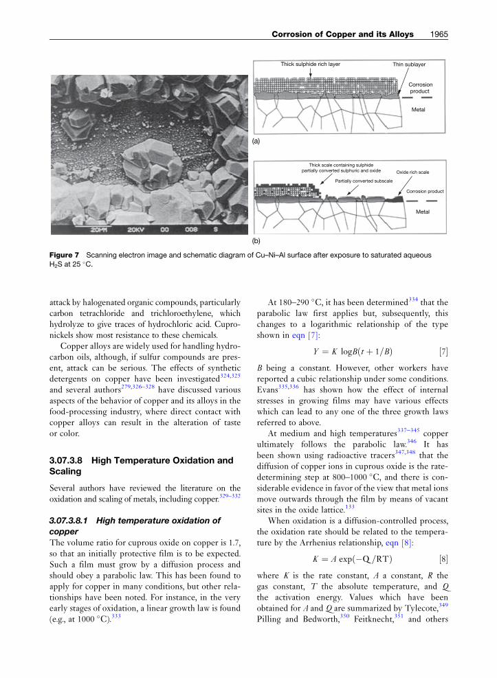
Thick sulphide rich layer
Thick scale containing sulphidepartially converted sulphuric and oxide
(a)
(b)
Thin sublayer
Corrosion product
Metal
Partially converted subscale
Oxide rich scale
Corrosion product
Metal
Figure 7 Scanning electron image and schematic diagram of Cu–Ni–Al surface after exposure to saturated aqueous
H2S at 25 �C.
Corrosion of Copper and its Alloys 1965
attack by halogenated organic compounds, particularlycarbon tetrachloride and trichloroethylene, whichhydrolyze to give traces of hydrochloric acid. Cupro-nickels show most resistance to these chemicals.
Copper alloys are widely used for handling hydro-carbon oils, although, if sulfur compounds are pres-ent, attack can be serious. The effects of syntheticdetergents on copper have been investigated324,325
and several authors279,326–328 have discussed variousaspects of the behavior of copper and its alloys in thefood-processing industry, where direct contact withcopper alloys can result in the alteration of tasteor color.
3.07.3.8 High Temperature Oxidation andScaling
Several authors have reviewed the literature on theoxidation and scaling of metals, including copper.329–332
3.07.3.8.1 High temperature oxidation of
copper
The volume ratio for cuprous oxide on copper is 1.7,so that an initially protective film is to be expected.Such a film must grow by a diffusion process andshould obey a parabolic law. This has been found toapply for copper in many conditions, but other rela-tionships have been noted. For instance, in the veryearly stages of oxidation, a linear growth law is found(e.g., at 1000 �C).333
At 180–290 �C, it has been determined334 that theparabolic law first applies but, subsequently, thischanges to a logarithmic relationship of the typeshown in eqn [7]:
Y ¼ K logBðt þ 1=BÞ ½7�B being a constant. However, other workers havereported a cubic relationship under some conditions.Evans335,336 has shown how the effect of internalstresses in growing films may have various effectswhich can lead to any one of the three growth lawsreferred to above.
At medium and high temperatures337–345 copperultimately follows the parabolic law.346 It hasbeen shown using radioactive tracers347,348 that thediffusion of copper ions in cuprous oxide is the rate-determining step at 800–1000 �C, and there is con-siderable evidence in favor of the view that metal ionsmove outwards through the film by means of vacantsites in the oxide lattice.133
When oxidation is a diffusion-controlled process,the oxidation rate should be related to the tempera-ture by the Arrhenius relationship, eqn [8]:
K ¼ A expð�Q =RTÞ ½8�where K is the rate constant, A a constant, R thegas constant, T the absolute temperature, and Q
the activation energy. Values which have beenobtained for A and Q are summarized by Tylecote,349
Pilling and Bedworth,350 Feitknecht,351 and others
1966 Non-Ferrous Metals and Alloys
and give values of Q of �0.17 MJ for temperaturesof 700–1000 �C, while at lower temperatures (upto 500 �C) Vernon352 and others have obtainedvalues of about 85 kJ. These values are in agreementwith calculations by Valensi,353 based on the assump-tion that, at high temperatures, the oxidation proceedsby the reaction of oxygen with metallic copper toproduce cuprous oxide while at lower temperaturesthe rate is determined by the reaction between oxygenand cuprous oxide to form cupric oxide.
At low temperatures (e.g., 300 �C) the film consistsalmost entirely of CuO. As the temperature increases,the film consists of a layer of Cu2O beneath a layerof CuO, the proportion of Cu2O increasing until,at high temperature, the film is almost entirelyCu2O. The precise composition of the film depends,however, on a number of factors, including tem-perature, time, and oxygen concentration in theatmosphere. Tylecote346 has investigated the compo-sition, properties, and adherence of scales formed onvarious types of copper at temperatures between 400and 900 �C. At the higher temperatures, the scalesformed on copper containing phosphorus were morebrittle and less adherent than those formed on coppercontaining no phosphorus.
Studies have been carried out on the effects athigh temperature of sulfur349 and of atmospherescontaining hydrogen sulfide,354–356 steam,357,358 sul-fur dioxide,358 and hydrogen chloride.358
3.07.3.8.2 High temperature oxidation of
copper alloys
In the case of copper alloys which contain elementswhich are more noble than copper, the resultingsurface oxide will be substantially pure copperoxide as the oxides of the noble metals have higherdissociation pressures than the copper oxides. Con-versely, for alloys containing baser metals, the alloy-ing element will appear as an oxide in the scale oftenin greater concentration than in the alloy itself, andsometimes to the exclusion of copper oxides. Thedissociation pressures of many oxides have been cal-culated by Lustman.359
Whether the rate of oxidation of an alloy of copperwith a base metal is less or more than that of copperwill depend on the concentration of the alloyingelement and the relative diffusion velocities ofmetal atoms or ions in the oxide layers. There isextensive literature on the oxidation behavior ofcopper alloys.346,347,360–367 According to Wagner’stheory368–371 the rate of oxidation will be largelyinfluenced by the electrical conductivity of the film
and this theory is supported by the fact that thealloying elements giving maximum oxidation resis-tance to copper, that is, beryllium, aluminum, andmagnesium, form oxides having very low conductiv-ities, as shown by Price and Thomas.372 Wagner cal-culated that when sufficient aluminum was present incopper to cause the formation of an alumina film, theoxidation rate should be decreased by a factor ofmore than 80 000. Experiment showed the factor tobe only 36, but when Price and Thomas carried outinitial oxidation under only slightly oxidizing condi-tions, producing only a film of alumina, the oxidationrate on subsequent exposure to full oxidizing conditionswas decreased by a factor of �240 000. Hallowes andVoce358 found that selective oxidation of a 95Cu–5Alalloy by this method gave protection from atmosphericoxidation up to 800 �C unless the film was scratched orotherwise damaged, or the atmosphere contained sulfurdioxide or hydrogen chloride.
The effects on oxidation resistance of copper as aresult of adding varying amounts of one or moreof aluminum, beryllium, chromium, manganese, sili-con, and zirconium are described in a number ofpapers.360–367 Other authors have investigated theoxidation of copper–zinc373,374 and cupronickelalloys,374,375 the oxidation of copper and copper–gold alloys in carbon dioxide at 1000 �C376 and theinternal oxidation of various alloys.377–379
Copper alloys have been used extensively in high-pressure feed-water heaters in power generatingplant.380 Experience has shown that when such hea-ters are operated intermittently, 70Cu–30Ni or80Cu–20Ni alloy tubes suffer fairly rapid and severesteam-side (external) oxidation with the formation ofexfoliating scales. This corrosion, which may be asso-ciated with ingress of air during shutdowns, has beenthe subject of several published papers.381–385 Thebehavior of other alloys for feed-water heater servicehas also been discussed.380,386–388
3.07.4 Protective Measures
The good corrosion behavior of copper and copperalloys is dependent upon correct choice of material,good design of equipment, and proper methods ofoperation. Brasses and bronzes may often be effec-tively protected by polishing followed by periodicwaxing. If proper attention is given to these factors,there will usually be no need for protective measures.In special cases, however, for example, to prevent thedissolution of small amounts of copper or to maintain
Corrosion of Copper and its Alloys 1967
a high-grade finish, metallic coatings of one or moreof the following metals may be applied: tin, lead,nickel, silver, chromium, rhodium, or gold. In othercases painting, varnishing, or lacquering may bedesirable, or if the conditions are very severe (as insome corrosive soils) heavier protection such as bitu-minous or plastic coatings may be necessary. Brassesthat are liable to suffer dezincification or stress cor-rosion may need protection where other copperalloys would be satisfactory in an unprotected condi-tion. Sometimes use is made of the principles ofcathodic protection, for example, steel ‘protectorblocks’ in condenser water-boxes.
In some circumstances, use of inhibitors may be adesirable remedial measure. For instance, benzotria-zole (BTAH) has been found of considerable valuefor preventing staining and tarnishing of copper pro-ducts.389 The characteristics of the behavior seenindicate that an inhibiting film is formed by adsorp-tion of neutral BTAH molecules on the copper sur-face followed by adsorption of a thin layer of copperBTAH in polymeric form. Also, a synergistic effecthas been found when BTAH and iodide ions areused together to prevent copper corrosion in sulfuricacid.390 Sodium diethyldithiocarbamate also has use-ful inhibiting properties.391 Other types of inhibitorscan be of value in condensate systems392,393 and inacid solutions.305–310 Reviews have been given ofcorrosion inhibitors for copper394 and brasses.395,396
The effects and efficiencies of various inhibitors con-tinues to be the subject of much research.397–400 Lowconcentrations (0.1 mM) of amino acids (glycine andcysteine) have been demonstrated to provide over95% inhibition efficiency for 95–5 cupronickelcorrosion.401
The danger of accelerated attack on copper-basematerials due to coupling with other metals is smallin many environments since copper is usually thecathodic member of the couple, but precautions areoften necessary to prevent excessive corrosion of theanodic member. Surveys of the behavior of couplesinvolving copper and copper alloys have beengiven.319 Titanium, high nickel alloys, and superstainless steels can be sufficiently more noble thancopper alloys in seawater environments to cause gal-vanic attack of the copper alloy and electrical isola-tion or insulated spool pieces may be required. Thisis less of a problem in chlorinated systems as preven-tion of the biofilm can reduce the efficiency of thecathode.319,402 Another material that has been foundcapable of accelerating attack on copper in practiceis graphite; hence graphitic paints or graphite in
gasketing, etc., are undesirable. Occasionally theaction between different copper-based materialsmay be appreciable particularly if the relative surfaceareas are unfavorable, for example, gunmetal maystimulate the corrosion of copper or brass in seawaterand due care should be taken.
3.07.5 Areas of Future Development
3.07.5.1 Antimicrobial Benefits of CopperCorrosion
The formation of cuprous Cuþ and cupric ions Cu2þ
has been described earlier. The ability of copper togain and lose outer electrons is the source of many ofcopper’s important physical properties such as highelectrical and thermal conductivity, chemical stabil-ity, and its reddish color. Copper ions also play acrucial role in copper’s antimicrobial action and themain hypotheses for the mode of actions in damagingthe functionality of a cell of a microorganism are:
1. Their competing with and hindering uptake ofmajor minerals such as sodium and potassium.This causes serious imbalances in the mineralcomposition of the cell of the microorganism.403
2. Their binding to proteins inside the cell which donot require copper, creating a dysfunction of thatprotein.404,405
3. Their causing oxidative damage, thereby damag-ing the cell wall and other cellular structures andfinally causing bacterial cell death.406
Recent work407–409 has shown the effectiveness ofcopper in inactivating pathogens such as Escherichiacoli, Meticillin-resistant Staphylococcus aureus (MRSA),and Influenza A and in reducing environmental con-tamination in a clinical setting.410,411
3.07.5.2 Alloy Developments
Cupronickel alloys in particular are being developedfor applications in seawater and oil and gas wellenvironments. Copper nickel chrome (DEF STAN02-824) cast components are beginning to replacethose made from nickel aluminum bronze whenlong-term seawater corrosion resistance is required.This is due to the fact that, after 10 years of seawaterservice, only such components have been found tohave lost only �0.15 mm from their original thick-ness through corrosion, performing significantly bet-ter than cast nickel aluminum bronze under the sameconditions.412 Cu–Ni–Al and Cu–Ni–Sn alloys are

1968 Non-Ferrous Metals and Alloys
being developed as high strength corrosion resistantalloys for seawater applications requiring hydrogen-embrittlement-free, antigalling properties, and as alter-native corrosion resistant, nonmagnetic bearing alloy toBe–Cu in directional oilfield drilling equipment.
Shape memory effect alloys have recently beenunder development for use in electronics and den-tistry. Those based on Cu–Al and Cu–Ag–Al havebeen found to exhibit curious electrochemical effectsduring dissolution in alkali media if oxygen is pres-ent.413 This has been explained in terms of fast pref-erential dissolution of aluminum followed by theslow transport of aluminate ions from the surface.This influences the formation of Cu2O, which is themain corrosion reaction, such that an unusual oscil-latory electro-potential effect is produced.
Acknowledgements
This section is comprised of a revised version of thechapter by P.T. Gilbert, which appeared in the previ-ous edition. This, in turn, was based on ‘ChemicalProperties and Corrosion Resistance of Copper andCopper Alloys,’ which formed Chapter XVIII of theAmerican Chemical Society Monograph No. 122,‘The Science and Technology of the Metal its Alloys and
Compounds,’ edited by Professor Allison Butts, andpublished by the Reinhold Publishing Corporation,New York, in 1954. Acknowledgement is herebymade to the Reinhold Publishing Corporation forpermission to make derivations from this work. Therevisions of the current chapter have also been con-tributed to by Peter Webster, Technical Consultant,and Angela Vessey, Director, Copper DevelopmentAssociation UK, Claes Taxen of KIMAB, Sweden andRolf Sundberg of Vasteras, Sweden, to whom furtheracknowledgements are given.
References
1. BSEN. Copper and Copper Alloys – Ingots and Castings,BSI: London, 1982.
2. CEN TC 133. CR 13388. Copper and Copper Alloys –Compendium of composition and products, BSI:London.
3. EN1652. Specifications for Copper and Copper Alloys:Plate, sheet, strip and circles for general purposes, EN12163 Rod, EN12166 Wire, EN 12449 Tubes, EN12420Forgings, BSI, London.
4. Copper and Copper Alloys; ASTM: Pittsburg, 2006.5. A1322. Standards Handbook for Wrought and Cast
Copper and Copper Alloy Products; CopperDevelopment Association Inc., New York, 2003.
6. Copper and Copper Alloys Compositions, Applicationand Properties; Publication 120, Copper DevelopmentAssociation: UK, 2004.
7. The Brasses-Properties and Applications; Publication117, Copper Development Association: UK, 2005.
8. DKI German Copper Institute Booklet: Copper nickelalloys; Properties, Processing, Application, DKI:Germany, 2000.
9. Powell, C. A.; Michels, H. T. Cupronickel Alloys forseawater corrosion resistance and antifouling – a state ofthe art review; Corrosion, NACE: Houston, 2000.
10. Powell, C. Corr. Management. 2005, 63, 8.11. DEF-STAN 02-824. Copper Nickel Chromium Sand
Castings and Ingots; UK Ministry of Defence, AbbeyWood: UK, 2002.
12. Gaffoglio, C. J. Power Eng. 1982, 60.13. Tuck, C. D. S.; Bendall, K. C.; Radford, G. W. J.;
Campbell, S. A.; Grylls, R. J. Paper No. 78, Corrosion/96,NACE: Houston, 1996.
14. Ratka, J. O.; Maligas, M. N. Paper No. 04298, Corrosion2004, NACE: Houston, 2004.
15. Ateya, B. G.; Elsayed, A. A.; Sayed, M. S. J. Electrochem.Soc. 1993, 141(1), 71–78.
16. Gatty, O.; Spooner, E. C. R. Electrode PotentialBehaviour of Corroding Metals in Aqueous Solutions;Clarendon Press: Oxford, 1938.
17. Pourbaix, M. J. N. Atlas of Electrochemical Equilibria inAqueous Solutions; Pergamon: Oxford, 1966.
18. Rubinic, L.; Markovic, T.Werkst. Korrosion 1959, 16, 666.19. Hickling, A.; Taylor, D. Trans. Faraday Soc. 1948.20. Kuksina, O. Y.; Kondrashin, V. Y.; Mashakov, I. K.
Protec. Met. (Russia) 2006, 42(2), 144.21. Mayer, S. T.; Muller, R. H. J. Electrochem. Soc. 1992,
139(2), 426–434.22. Kusina, O. Y.; Kondrashin, V. Y.; Marshakov, I. K.
Protect. Met. (Russia) 2004, 40(6), 581.23. Wilde, B. E.; Teterin, G. A. Br. Corros. J. 1967, 2, 125.24. Mansfield, F.; Uhlig, H. H. J. Electrochem. Soc. 1970,
117, 427.25. Varenko,E.S.;Galushko,V.P.; Kovtan,V.N.; Fedash,P.M.;
Loshkarev, Y. M. Zashchita Metallov 1970, 6, 103.26. Gavgahi, M.; Kaymaz, I.; Totik, Y.; Sadeler, R. Corr. Rev.
2002, 20(4–5), 403.27. Virtanen, S.; Wojtas, H.; Schmuki, P.; Bohni, H.
J. Electrochem. Soc. 1993, 140(10), 2786–2790.28. Parvizi, M. S.; Aladjem, A.; Castle, J. E. Int. Mater. Rev.
1988, 33(4), 169.29. Mathiyarasu, J.; Palaniswamy, N.; Muraldharan, V. S.
Corr. Rev. 2000, 18(1), 65.30. Badawy, W. A.; Ismail, K. M.; Fathi, A. M. Electrochimica
Acta 2005, 50(18), 3603.31. Vernon, W. H. J. J. Inst. Met. 1932, 49, 153.32. Vernon, W. H. J.; Whitby, L. J. Inst. Met. 1929, 42, 181;
1932, 44, 389.33. Vernon, W. H. J. Trans. Faraday Soc. 1931, 27, 255, 582.34. Baumann, K.; Ruhrberg, U.; Kreysa, G. DECHEMA-
Werkstoffe-Tabelle, 37th Supplement (Atmosphere),DECHEMA: Frankfurt, 1995.
35. Hudson, J. C. Trans. Faraday Soc. 1929, 25, 177; J. Inst.Met. 1930, 44, 409; J. Birmingham Met. Soc. 1934, 14,331; Met. Ind. 1934, 44, 415; J. Inst. Met. 1935, 56, 91.
36. Tracy, A. W.; Thompson, D. H.; Freeman, J. R. SpecialTechnical Publication No. 175; ASTM: Pittsburgh, 1955;pp 77–87.
37. Mattsson, E.; Holm, R. Metal Corrosion in theAtmosphere; STP 435; ASTM: Pittsburgh, 1968; p 187.
38. Scholes, I. R.; Jacob, W. R. J. Inst. Met. 1970, 99, 272.39. Morcillo, M.; Almeida, E.; Marmcos, M.; Rosales, B.
Corrosion 2001, 57(11), 967.
Corrosion of Copper and its Alloys 1969
40. Thompson, D. H. Metal Corrosion in the Atmosphere;STP 435; ASTM: Pittsburgh, 1968; p 129, 199.
41. Holm, R.; Mattsson, E. Atmospheric Corrosion of Metals;STP 767; ASTM: Pittsburgh, 1982; p 85.
42. Ramos, A. C.; Camoes, M. F.; Mendonca, M. H.;Foneca, I. I. E. Corr. Prot. Mater. 2001, 20(4), 16.
43. Tracy, A. W. STP No. 175; ASTM: Pittsburgh, 1955;pp 67–76.
44. Tidblad, J.; Leygraf, C.; Kucera, V. J. Electrochem. Soc.1991, 138(12), 3592–3598.
45. Eriksson, P.; Johansson, L.-G.; Strandberg, H. J.Electrochem. Soc. 1993, 140(1), 53–59.
46. Strandberg, H.; Johansson, L.-G. J. Electrochem. Soc.1998, 145(4), 1093.
47. Knotkova, D. Proceedings of 12th International CorrosionCongress, Houston; NACE: Houston; Sept 1993; Vol. 2,p 51.
48. Laub, H. Metallurgy 1968, 22, 1116.49. Veleve, L.; Luja, M. Br. Corr. J. 1999, 34(1), 34.50. Hullman, H. Proceedings of UN ECE Workshop, Munich,
May 2003; Swedish Corrosion Institute, Stockholm, 2003.51. Priggemeyer, S. Report AZ 10730, Deutsche
Bundesstiftung Umwelt; 1998.52. Priggemeyer, S.; Priggemeyer, S. Metallurgy 1999, 53,
204.53. Leuenberger-Minger, A. U.; Faller, M.; Richner, P. Mat.
Corr. 2002, 54(3), 157.54. UN ECE-Report. Investigation of the Metal Run-off from
Copper Surfaces exposed to Atmosphere; Bulletin –Korrosions Institutet, 2003, ISSU 109E.
55. Odnevall Wallinder, I.; Leygraf, C. J. Corr. Sci. 1997, 39,2039.
56. Bertling, S.; Odnevall Wallinder, I.; Berggren Kleja, D.;Leygraf, C. Environ. Toxicol. Chem. 2006, 25, 891.
57. Odnevall Wallinder, I.; Bahar, B.; Leygraf, C.; Tidblad, J.J. Environ. Monit. 2007, 9, 66.
58. Sandberg, I.; Odnevall Wallinder, I.; Leygraf, C.;Le Bozec, N. J. Corr. Sci. 2006, 39, 4316.
59. Karlen, C.; Odnevall Wallinder, I.; Heijerick; Leygraf, C.Environ. Pollut. 2002, 120, 691.
60. Odnevall Wallinder, I.; Leygraf, C. J. Corr. Sci. 2001, 43,2379.
61. Odnevall Wallinder, I.; Verbiest, P.; He, W.; Leygraf, C. J.Corr. Sci. 2000, 42, 1471.
62. Sundberg, R. Metallurgy 2005, 59, 10.63. Arnold, R. Integrat. Environ. Assess. Mgmt. 2005, 1, 333.64. Boulanger, B.; Nikolaidis, N. P. J. Am. Water Resources
Assn. 2003, 39, 325.65. Romanoff, M. Underground Corrosion; Nat. Bur. Stand.
Circ. 579; Supt.of Documents: Washington, D.C, 1957.66. Gilbert, P. T. J. Inst. Met. 1947, 7, 139.67. Gilbert, P. T.; Porter, F. C. Iron and Steel Institute Special
Report No. 45, 1952, pp 55–74, pp 127–134.68. Markovic, T.; Sevic, M.; Rubinic, L. Werkst. Korrosion
1960, 11, 87.69. Maeda, M.; Tenyama, K.; Shibayanagi, T.; Naka, M.
Mater. Charac. 2005, 55(2), 127.70. Angelini, E.; Mongiatti, A.; Grassini, S.; Rosalbino, F.;
Ingo, G. M.; De Caro, T. EUROCORR 2004, Nice, Sept2004. Published CEFRACOR: Paris, 2004.
71. Efird, K. D. Corrosion 1977, 33(1), 347.72. Obrecht, M. F. Corrosion 1962, 18, 189t.73. Solelev, A. J. Inst. Wat. Engrs. 1955, 9, 208.74. Gilbert, P. T. Br. Corr. J. 1979, 14, 20.75. Aluminium Bronze Alloys Corrosion Resistance Guide;
Publication 80, Copper Development Association, UK,1981.
76. Defence Standard 01-782. Protection of SeawaterSystem Pipework and Heat Exchanger Tubes in HM
Surface Ships and Submarines; UK Ministry of Defence,Abbey Wood, 2009.
77. Kirk, W. Evaluation of Critical Seawater HydrodynamicEffects of Erosion Corrosion of CuNi, INCRA Report 3961987.
78. Beckmann, W.; Hecht, M.; Jasner, M.; Steinkemp, K.Kuala Lumpur Fabrication Technology Corrosion2001, Kuala Lumpur; Institute of Materials: London,2000.
79. LaQue, F. L. Proc. Am. Soc. Test. Mater. 1952, 52, 1.80. Evans, U. R. J. Electrochem. Soc. 1939, 75, 446;
Fink, F.W. J. Electrochem. Soc. 1939, 75, 446, 441.81. Lucey, V. F. Br. Corr. J. 1965, 1(9), 53.82. Feller, H.-G. Z. Metallkunde 1967, 58, 875.83. Heidersbach, R. Corrosion 1968, 24, 38.84. Kenworthy, L.; O’Driscoll, W. G. Corr. Technol. 1955, 2,
247.85. Piatti, L.; Grauer, R. Werkst. Korrosion 1963, 14, 551.86. Hashimoto, K.; Ogawa, S.; Shimodaira, S. Trans. Jpn.
Inst. Met. 1963, 4, 42.87. Sugawara, H.; Ebiko, H. Corr. Sci. 1967, 7, 513.88. Joseph, G.; Arce, M. T. Corr. Sci. 1967, 7, 597.89. Langenegger, E. E.; Robinson, F. P. A. Corrosion 1968,
24, 411; 1969, 25, 59.90. Horton, R. M. Corrosion 1970, 26, 160.91. Rothenbacher, P. Corr. Sci. 1970, 10, 391.92. Potzl, A.; Lieser, K. H. Z. Metallkunde 1970, 61, 527.93. Sundberg, R.; Holm, R.; Hertzman, S.; Hutchinson, B.;
Lindh-Ulmgren, E. Metallurgy 2003, 57, 721.94. Hutchinson, B.; Oliver, J.; Lindh-Ulmgren, E.;
Symniotis, E. In Investigation into the Dezincification ofa-Brass; Proceedings of the International ConferenceCopper 2006; Welter, J.-M. Ed.; Wiley-VHC, 2006.
95. Bengough, G. D.; Jones, R. M.; Pirret, R. J. Inst. Met.1920, 23, 65.
96. Upton, B. Br. Corros. J. 1966, 1, 134.97. Baldwin, A. B.; Campbell, H. S. Brit. Waterworks
Assoc. J. 1961, 43, 13.98. Schafer, G. J.; Dall, R. A. Aust. Corr. Eng. 1966, 10, 39.99. Ladeburg, H. Metallurgy 1966, 20, 33.
100. Simmonds, M. A.; Huxley, W. G. S. Aust. Corr. Eng. 1967,11, 9.
101. Bengough, G. D.; May, R. J. Inst. Met. 1924, 32, 81;Discussion of Bradbury, E. J.; Johnson, L. W. Trans. Inst.Mar. Engrs. 1951, 63, 59.
102. Breckon, C.; Gilbert, P. T. Chem. Ind. 1964, 4, 35.103. Bem, R. S. The Engineer 1958, 206, 756.104. Sundberg, R.; Hertzman, S.; Linder, M. In Intergranular
Corrosion (IGA) of Brass; Proceedings of the InternationalConference Copper 2006 Welter, J.-M. Ed.; Wiley-VHC,2006.
105. Mazza, F.; Torchio, S. J. Corr. Sci. 1983, 23, 1053.106. Tumer, M. E. D. Proc. Soc. Water Treatm. Exam. 1961,
10, 162; 1965, 14, 81.107. Clark, W. D. J. Inst. Met. 1947, 73, 263.108. Breckon, C.; Gilbert, P. T. Proceedings of the first
International Congress on Metal Corrosion, London;Butterworths: London, 1962; p 624.
109. Meigh, H. Cast and Wrought Aluminum Bronzes –Properties, Processes and Structure; IOMCommunications, 2000.
110. Brezina, P. Int. Met. Rev. 1982, 27(2), 1.111. Weill-Couly, P.; Arnoud, D. Fonderie 1973, 322.112. Taxen, C. Korrosioninstitutet Rapport 1996, 8, 1.113. Campbell, H. S. Chem. Ind. 1955, 692.114. Hatch, G. B. J. Am. Waterworks Assn. 1961, 53, 1417.115. Hatch, G. B. NACE Tech. Rep. 60–11; Corrosion 1960,
16, 453t.116. Schafer, G. J. New Zealand J. Sci. 1962, 5, 475.
1970 Non-Ferrous Metals and Alloys
117. Lucey, V. F. Br. Corr. J. 1967, 2, 175.118. Campbell, H. S. Proceedings of the second International
Congress on Metal Corrosion, New York (1963); NACE:Houston, 1966; p 237.
119. Gilbert, P. T. Aust. Corr. Eng. 1969, 13, 513.120. Zhu, X.; Lei, T. J. Mat. Sci. Technol. (China) 1998,
14(1), 57.121. Lin, L.; Lui, S.; Lui, Z.; Xu, J. Corr. Sci. Protect. Technol.
1999, 11(1), 37.122. Sundberg, R. Metallurgy 2002, 56(11), 714.123. Schafer, G. J.; Dall, R. A. Aust. Corr. Eng. 1963, 7(10), 33.124. Proceedings of the International Corrosion of Copper &
Copper Alloys in Building; Tokyo, Japanese CopperDevelopment Association, 1982.
125. Cornwall, F. J.; Wildsmith, G.; Gilbert, P. T. Br. Corr. J.1973, 8, 202.
126. Oliphant, R. J. Causes of Copper Corrosion inPlumbing Systems; Foundation for Water Research,2003.
127. Mattson, E.; Fredriksson, A.-M. Br. Corr. J. 1968, 3, 246.128. Mattson. E., Werkst. U Korros. 1988, 39, 499.129. Linder, M. Proceedings of the 9th Scandinavian
Corrosion Congress, Copenhagen, 1983, pp 569–581.130. Drogowska, M.; Brossard, L.; Menard, H.
J. Electrochem. Soc. 1992, 139(1), 39–47.131. Milosev, I.; Metikos-Hukovic, M.; Drogowska, M.;
Menard, H.; Brossard, L. J. Electrochem. Soc. 1992,139(9), 2409–2418.
132. Drogowska, M.; Brossard, L.; Menard, H.J. Electrochem. Soc. 1993, 140(5), 1247–1251.
133. BSEN 12502:2004. Protection of metallic materialsagainst corrosion. Guidance on the assessment ofcorrosion likelihood in water distribution and storagesystems. Influencing factors for cast iron, unalloyed andlow alloyed steels and BSEN 14868:2005, Protection ofMetallic Materials against Corrosion. Guidelines on theassessment of corrosion likelihood in closed watercirculation systems, BSI, UK, 2005.
134. Rogers, T. H. J. Inst. Met. 1948, 75, 19–38.135. Keevil, C. W.; Walker, J. T.; McAvoy, J.; Colbourne, J. S.
In Biocorrosion; Gaylarde, C. C., Moreton, L. H. G., Eds.;Biodeterioration Society: Kew, 1988.
136. Wagner, D.; Fischer, W.; Tuschewitzki, G. J.Microbiologically influenced corrosion of copper pipesFinal report, ICA project number 453, 1992.
137. Geesey, G. G; Mittleman, M.W.; Iwaoka, T.; Griffiths, P. R.Materials Performance 1986, 37–40.
138. Geesey, G. C.; Lewandowski, Z.; Fleming, H.-C.Biofouling/Biocorrosion in Industrial Water Systems;Lewis Publishers: Chelsea, MI, 1993.
139. Tronstad, R.; Veimo, R. J. Inst. Met. 1940, 66, 17.140. Kenworthy, L. J. Inst. Heat. Vent. Engst. 1940, 8, 15.141. Gilbert, P.T. Proc. Soc. Water Treatm. Exam. 1966,
15, 165.142. Priggemeyer, St.; Priggemeyer, S.; Meyer, E.; Sauter, W.;
Breu, M.; Schuz, G.; Arens, P.; Baukloh, A. In CopperRelease of Copper Tubes in Contact with Hard DrinkingWaters, Conference Proceedings of CEOCOR PlenaryMeeting 2001; Biarritz.
143. Critchley, M.; Taylor, R.; O’Halloran, R. Mater. Perform.2005, 44(6), 56.
144. Merkel, T. H.; Pehkonen, S. O. Corr. Eng. Sci. Technol.2006, 41(1), 21–37.
145. Kenworthy, L. J. Inst. Met. 1943, 69, 67.146. Porter, F. C.; Hadden, S. E. J. Appl. Chem. 1953, 3, 385.147. Guidelines for Drinking Water Quality, 3rd ed.; WHO:
Geneva, 2008.148. Araya, M.; McGoldrick, M. C.; Klevay, L. M.; Strain, J. J.;
Robson, P.; Nielsen, F.; Olivares, M.; Pizarro, F.;
Johnson, L.; Poirier, K. A. Regulat. Toxicol. Pharmacol.2001, 34, 137–145.
149. Davenport, W. H.; Nole, V. F.; Robertson, W. D.J. Electrochem. Soc. 1959, 106, 1005.
150. Ives, D. J. G.; Rawson, A. E. J. Electrochem. Soc. 1962,109, 447.
151. Obrecht, M. F.; Pourbaix, M. J. Am. Waterworks Assoc.1967, 59, 977.
152. Grunau, E. B. Stadtehygiene 1967, 7, 153.153. Tuthill, A. H. Mater. Perfor. 1987, 26(9), 12.154. Defence Standard 01/2 and Angell, B.; Tuck, C. D. S.,
private communications, UK Ministry of Defence,Bristol, UK.
155. Shone, E.; Grim, G. Trans I. Mar. Eng. 1976, 98, Paper 11.156. Kirk, W.; Tuthill, A. The Application of Copper Nickel
Alloys in Marine Systems. Copper Nickel Condenser andHeat Exchanger System, CDA Inc Seminar TechnicalReport 7044–1919, CDA, Inc: New York, 1992.
157. Jasner, M.; Hecht, M.; Beckman, W. Heat Exchangersand Piping Systems from Copper Alloys –Commissioning, Operating and Shutdown; KME:Osnabruck, 1998.
158. Gilbert, P. T. Conference of Historical Metallurgy Society,Birmingham, Paper Copper 4, 1984.
159. Powell, C. A.; Michels, H. T. Cupronickel Alloys forseawater corrosion resistance and antifouling – A State ofthe Art review; Corrosion 2000; NACE: Houston, 2000.
160. Zhu, X.; Lin, L.; Lei, T. Acta Metall. Sinica (China) 1997,33(12), 1256.
161. Zhu, X.; Lin, L.; Xu, J.; Lei, T. Chin. J. Non-ferrous Met.1997, 7(2), 79.
162. Nicklin, G. J. E. Living with the threat of microbiologicallyinfluenced corrosion in submarine seawater systems-theRoyal Navy’s perspective. Proceedings of 9thInternational Naval Engineering Conference (INEC 2008),Hamburg, IMarEST, London, 2008.
163. Schleich, W. Corrosion 2005; NACE: Houston, 2005,Paper No. 5222.
164. Theile, E. W. Proceedings of CDA Heat ExchangerSeminar; New York, April; Copper DevelopmentAssociation: New York, 1981.
165. Sato, S. Proceedings of the fourth InternationalCongress of Metal Corrosion Amsterdam, 1969; NACE:Houston, 795, 1972.
166. i,s Lee, T. S. Pre-treatment of Condenser Tubing forEnhanced Corrosion Resistance; INCRA Project 284Final Report, NiDI, 1985.
167. Rowlands, J. C. J. Appl. Chem. 1965, 15, 57.168. Lemieux, E.; Wolejsza, T. M.; Grolleau, A. M. Corrosion
2002; Denver; NACE: Houston, 2002, Paper No. 02210.169. Berthagen, L. The use of Cathodic Protection for Copper
Alloys in Seawater Cooling Systems, EFC Working PartyReport, EuroCorr 2001, Maney Publishing: London, 2001.
170. Tuthill, A. H.; Todd, B.; Oldfield, J. IDA World Congresson Desalination and Water Reuse; Madrid 1997; Vol. IIIp251p 25, paper No. 73.
171. Oldfield, J. W.; Todd, B. A Review of Materials andCorrosion in Desalination-Key Factors for PlantReliability; IDA World Congress on Desalination andWater Science: Abu Dhabi, 1995.
172. Gilbert, P. T.; Jenner,B. J. InternationalMarine andShippingConference; Institute of Marine Engineers: London, 1969.
173. Li, W.; Lui, D.; Wei, K. Corr. Sci. Protect. Technol. 1995,7(3), 232.
174. Sigh, I.; Basu, D. K.; Singh, M. N.; Battamishra, A. K. Anti-Corrosion Meth. Mat. 1993, 44(3), 195.
175. Nelson, G. A. Bull. Am. Soc. Test. Mat. 1959, 240, 39.176. Agarwal, D. C. Br. Corr. J. 2002, 37(2), 105.177. Agarwal, D. C. Corr. Eng. Sci. Technol. 2003, 38(4), 275.
Corrosion of Copper and its Alloys 1971
178. Agarwal, D. C.; Sarin, S.; Wadhura, R.; Vishwakarma, R.;Deshmukh, M. B.; Kurian, S. J. Failure Anal. Prev. 2005,5, 70.
179. Slusser, J. W.; Dean, S. W.; Drummer, D. M. Corrosion’86 NACE: Houston, 1986, Paper 330.
180. Parkins, R. N.; Holroyd, N. J. H. Corrosion 1982,38, 245.
181. Robertson, W. D. Trans. Amer. Inst. Min. (Metall.) Engrs.1951, 191, 1190.
182. Edmunds, G. Symposium on Stress-corrosion Crackingin Metals; ASTM: Philadelphia, 1944; pp 67–89.
183. Elliot, P.; Corbett, R. A. In Corrosion/1999 NACE:Houston, 1999, Paper No. 342.
184. Wilson, T. C.; Edmunds, G.; Anderson, E. A.; Peirce,W.M.Symposium on Stress-corrosion Cracking in Metals;ASTM: Philadelphia, 1944; pp 173–193.
185. Sato, S.; Nosetani, T. Sumitomo Light Metal Tech. Rep.1969, 10(2), 83.
186. Syrett, B. C.; Parkins, R. N. Corr. Sci. 1970, 10, 197.187. Uhlig, H. H. Ed. Corrosion Handbook; Wiley: New York,
1948; pp 78–79.188. Sato, S. Sumitomo Light Met. Tech. Rep. 1960, 1(3), 45.189. Kamath, K. V.; Erdmann-Jesnitzer, F. Metallurgy 1960,
14, 1061.190. Thompson, D. H. Chem. Eng. 1961, 68(3), 130.191. Laub, H. Metallurgy. 1966, 20, 1174.192. Adamson, K. Corr. Sci. 1967, 7, 537.193. Erdmann-Jesnitzer, F.; Kacslingk, N. Werkst. Korrosion
1969, 20, 493.194. Copper Alloys-ammonia test for stress corrosion
resistance, ISO 6957; BSI: London, 1988.195. Wrought copper and copper alloys. Detection of residual
stress.Mercurousnitrate test, ISO 196; BSI: London, 1995.196. Helling, S.; Lissner, O.; Rask, S.; Strom, B. Werkst.
Korrosion 1957, 8, 569.197. Aebi, F. Z. Metallk. 1958, 49, 63.198. Thompson, D. H. Mater. Res. Standards 1961, 1, 108.199. Szabo, E. Werkst. Korrosion 1963, 14, 162.200. Mattsson, E.; Lindgren; Rask, S.; Wennstrom, G. Current
Corrosion Research in Scandinavia; KemianKeskususliitto: Helsinki, 1965; p 171.
201. Baumann, G. Werkst. Korrosion 1962, 13, 737.202. Sato, S. Sumitomo Light Metal Tech. Rep. 1963, 4(1), 48.203. Uhlig, H. H.; Sansone, J.Mater. Protection 1964, 3(2), 21.204. Peters, B. F.; Carson, J. A. H.; Barer, R. D. Mater.
Protect. 1965, 4(5), 24.205. Logan, H. L.; Ugiansky, G. M. Mater. Protect. 1965,
4(5), 79.206. Laub, H. Metallurgy 1966, 20, 597.207. Laub, H. Metallurgy 1967, 21, 173.208. Laub, H. Metalloberflache 1966, 20, 413, 453, 493.209. Sato, S.; Nosetani, T. Sumitomo Light Metal Tech. Rep.
1969, 10(3), 175.210. Whitaker, M. E. Metal. Manchr. 1948, 39, 21, 66.211. Perryman, E. C. W.; Goodwin, R. J. J. Inst. Met. 1954,
13, 378.212. Bailey, A. R. J. Inst. Met. 1959, 87, 380.213. Sheehan, T. L.; Dickerman, H. E. J. Am. Soc. Nav. Engrs.
1946, 58, 586.214. Evans, U. R. Symposium on Internal Stresses in
Metals and Alloys; Institute of Metals: London, 1947;pp 291–310.
215. Pugh, E. N.; Craig, J. V.; Montague, W. G. ASM.Trans. Quart. 1968, 61, 468.
216. Mattsson, E. Electrochim. Acta 1961, 3, 279.217. Forty, A. J.; Humble, P. Philos. Mag. 1963, 8(86), 247.218. Proceedings of the Second International Conference of
Metal Corrosion, New York (1963); NACE: Houston,1966; p 80.
219. McEvily, A. J., Jr.; Bond, A. P. J. Electrochem. Soc. 1965,112, 131.
220. Forty, A. J. Met. Progr. 1959, 75, 154.221. Graf, L.; Lacour, H. R. Z. Metallk. 1960, 51, 152; 1962,
53, 764.222. Graf, L.; Richter, W. Z. Metallk. 1961, 52, 834.223. Aebi, F. Z. Metallk. 1955, 46, 547; 1956, 47, 421.224. Bakish, R.; Robertson, W. D. J. Electrochem. Soc. 1956,
103, 320.225. Edeleanu, C.; Forty, A. J. Philos. Mag. 1960, 5(58),
1029.226. Graf, L. Metallurgy 1964, 18, 1163, 17.227. Lynes, W. Corrosion 1965, 21, 125.228. Pugh, E. N.; Westwood, A. R. C. Philos. Mag. 1966,
13, 167.229. Pugh, E. N.; Montague, W. G.; Westwood, A. R. C. ASM.
Trans. Quart. 1965, 58, 665.230. Hoar, T. P.; Booker, C. J. L. Corr. Sci. 1965, 5, 821.231. Fairman, M. Corr. Sci. 1966, 6, 37.232. Takano, M.; Shimodaira, S. Corr. Sci. 1968, 8, 55.233. Lahiri, A. K. Br. Corr. J. 1968, 3, 289.234. Lahiri, A. K.; Banerjee, T. J. Corr. Sci. 1968, 8, 895.235. Hoar, T. P.; Rothwell, G. P. Electrochim. Acta 1970,
15, 1037.236. Swann, P. R.; Nutting, J. J. Inst. Met. 1960, 88, 478.237. Swann, P. R. Corrosion 1963, 19, 102t.238. Swann, P. R.; Pickering, H. W. Corrosion 1963, 19, 369t,
373t.239. Tromans, D.; Nutting, J. Corrosion 1965, 21, 143.240. Brown, B. F. Met. Mater. 1968, 2(12), 171.241. Graf, L. Werkst. Korrosion 1969, 20, 408.242. Robertson, W. D. Ed. Stress Corrosion Cracking and
Embrittlement (Electrochem. Soc. Symposium); Wiley:New York, 1956.
243. Rhodin, T. N. Ed. Physical Metallurgy of Stress-CorrosionFracture (AIME Symposium); Interscience: New York,1959.
244. Conference on Fundamental Aspects of StressCorrosion Cracking, Ohio State University, 1967; NACE:Houston, 1969.
245. Bailey, A. R. Metall. Rev. 1961, 6(21), 101.246. Sparks, J. M.; Scully, J. C. J. Corr. Sci. 1974, 16, 619.247. Kermani, M.; Scully, J. C. J. Corr. Sci. 1978, 18, 833;
1979, 89, 489.248. Scully, J. C. Met. Sci. 1978, 12, 290; J. Corr. Sci. 1980,
20, 297.249. Takano, M.; Staehle, R. W. Trans. Jpn. Inst. Met. 1978,
19, 1.250. Takano, M. Trans. Jpn. Inst. Met. 1977, 18, 787.251. Takano, M. Corrosion 1974, 30, 441.252. Kawashima, A.; Agrawal, A. K.; Staehle, R. W. Spec.
Tech. Pub. 1979, 665, 266.253. Uhlig, H.; Gupta, K.; Liang, W. J. Electrochem. Soc.
1975, 122, 343.254. Holroyd, N. J. H.; Hardie, D.; Pollock, W. J. Br. Corr. J.
1982, 17, 103.255. Logan, H. L. Meta. Eng. Quart. 1965, 5, 32.256. Parkins, R. N. Metall. Rev. 1964, 9(35), 201.257. Engel, H.-J.; Speidel, M. O. Werkst. Korrosion 1969,
20, 281.258. Thompson, D. H.; Tracy, A. W. J. Met. N.Y. 1949, 1,
100.259. Pugh, E. N.; Montague, W. G.; Westwood, A. R. C. Corr.
Sci. 1966, 6, 345.260. Uhlig, H. H.; Duquette, D. J. J. Corr. Sci. 1969, 9, 557.261. White, L. F.; Blazey, C. Met. Ind. 1949, 75, 92.262. Sylwestrowicz, W. D. Corrosion 1969, 25, 168, 405;
1970, 26, 160.263. Lahiri, A. K.; Banerjee, T. Corr. Sci. 1965, 5, 731.
1972 Non-Ferrous Metals and Alloys
264. Chatterjee, U. K.; Sircar, S. C.; Banerjee, T. Corrosion1970, 26, 141.
265. Chatterjee, U. K.; Sircar, S. C. Br. Corros. J. 1970, 5, 128.266. Blackwood, A. W.; Stoloff, N. S. ASM. Trans. Quart.
1969, 62, 677.267. Harry Meigh. Cast and Wrought Aluminum
Bronzes-Properties, Processes and Structure; IOMCommunications, 2000.
268. Helliwell, B. J.; Williams, K. J. Metallurgia 1970, 81, 131.269. Nishimara, R.; Yoshida, T. Corr. Sci. 2008, 50(4), 1205.270. Thompson, D. H. Corrosion 1959, 15, 433t.271. Marshall, T.; Hugil, A. J. Corrosion 1957, 13, 329t.272. Klement, J. F.; Maersch, R. E.; Tully, P. A. Corrosion
1959; 15p 295t.273. Norden, R. B. Chem. Eng. 1958, 65, 194, 196.274. Klement, J. F.; Maersch, R. E.; Tully, P. A. Met. Prog.
1959, 75, 82; Corrosion, 1960, 16, 519t; U.S. Pat. 2 829972.
275. Robertson, W. D.; Grenier, E. G.; Davenport, W. H.;Nole, V. F. Met. Prog. 1959, 75, 152; U.K. Pat. 802 044.
276. Andersen, M. W.; Joosten, M.; Murali, J.; Milliams, D. E.Corrosion/96; NACE: Houston, 1996, Paper No. 78.
277. Tuck, C. D. S. Corrosion 2005; NACE: Houston, 2005,Paper No. 5462.
278. El Domiaty, A.; Alhajji, J. N. J. Mat. Eng. Perform. 1997,6(4), 534.
279. Pound, B. G. Corrosion 1994, 50(4), 301.280. Lee, J. A.Materials of Construction for Chemical Process
Industries; McGraw-Hill: New York, 1950.281. Rabald, E. Corrosion Guide; Elsevier: New York, 1951.282. LaQue, F. L. Corrosion 1954; 10p 391.283. Heim, A. T. Ind. Eng. Chem. 1957, 49, 63A, 64A, 66A.284. Baker, S. Corr. Technol. 1961, 8, 8.285. Tracy, A. W. Chem. Eng. 1962, 69, 130, 152.286. Gould, A. J.; Evans, U. R. J. Iron Steel Inst. 1947, 155,
195.287. Lacan, M.; Markovic, T.; Rubinic, L. Werkst. Korrosion
1959, 10, 767.288. Holmberg, M. E.; Prange, F. A. Ind. Eng. Chem. 1945, 37,
1030.289. Lingnau, E. Werkst. Korrosion 1957, 8, 216.290. Fontana, M. G. Ind. Eng. Chem. 1950, 42, 69A.291. Groth, V. J.; Hafsten, R. J. Corrosion 1954, 10, 368.292. Bulow, C. L. Chem. Eng. 1946, 53, 210.293. Friend, W. Z.; Mason, J. F.Corrosion 1949, 5, 355; NACE,
Report; Corrosion 1957, 13, 757t.294. Russell, R. P.; White, A. Ind. Eng. Chem. 1927,
19, 116.295. Damon, G. H.; Cross, R. C. Ind. Eng. Chem. 1936,
29, 231.296. Cornet, I.; Barrington, E. A.; Behrsing, G. U.
J. Electrochem. Soc. 1961, 108, 947.297. Caney, R. J. T. Aust. Eng. 1954, 64, 54; U.K. Pat 718,987.298. Zitter, H.; Kraxner, G. Werkst. Korrosion 1963, 14, 80.299. Piatti, L.; Fot, E. Werkst. Korrosion 1964, 15, 27.300. Gregory, D. P.; Riddiford, A. C. J. Electrochem. Soc.
1960, 107, 950.301. Talati, J. D.; Desai, M. N.; Trivedi, A. M.Werkst. Korrosion
1961, 12, 422.302. Graydon, W. F. J. Electrochem. Soc. 1962, 109, 1130.303. Kagetsu, T. J.; Gradon, W. F. J. Electrochem. Soc. 1963,
110, 856.304. Feller, H.-G. Corr. Sci. 1968, 8, 259.305. Otsuka, R.; Uda, M. Corr. Sci. 1969, 9, 703.306. Rana, S. S.; Desai, M. N. Indian J. Technol. S 1967, 393.307. Desai, M. N.; Shah, Y. C. Anti-Corr. Meth. Mater. 1968,
15(12), 9.308. Desai, U.; Gandhi, M. H. Corr. Sci. 1969, 9, 65.309. Padma, D. K. Anti-Corr. Meth. Mater. 1969, 16, 4.
310. Desai, M. N.; Shah, Y. C.; Punjani, B. K. Br. Corr. J. 1969,4, 309.
311. Ammar, I. A.; Riad, S. Corr. Sci. 1969, 9, 423.312. Desai, M. N.; Rana, S. S. Werkst. Korrosion 1966, 17,
870.313. Radley, J. A.; Stanley, J. S.; Moss, G. E. Corr. Technol.
1959, 6, 229.314. Schaefer, B. A. Corr. Sci. 1968, 8, 623.315. Bartonicek, R.; Holinka, M.; Lukasovska, M. Werkst.
Korrosion 1968, 19, 1032.316. Green, J. A. S.; Mengelberg, H. D.; Yolken, H. T. J.
Electrochem. Soc. 1970, 117, 433.317. Jenkins, L. H.; Durham, R. B. J. Electrochem. Soc. 1970,
117, 768.318. Dubrisay, R.; Chesse, G. Comp. Rend. Acad. Sci. Paris
1945, 220, 707.319. Francis, R. The Selection of Materials for Seawater
Cooling Systems – A Practical Guide for Engineers;NACE Publication, 2006.
320. Campbell, S. A.; Radford, G. J. W.; Tuck, C. D. S.;Barker, B. D. Corrosion 2002, 58(1), 57.
321. Reichert, J. S.; Pete, R. H. Chem. Eng. 1947, 54, 218.322. West, J. R. Chem. Eng. 1951, 58, 281.323. Botham, G. H.; Dummett, G. A. J. Dairy Res. 1949, 16, 23.324. Holness, H.; Ross, T. K. J. Appl. Chem. 1951, 1, 158.325. Bukowiecki, A. Schweizer Archiv. Angew. Wiss. 1958,
24, 355.326. Mason, J. F. Corrosion 1948, 4, 305.327. Inglesent, H.; Storrow, J. A. J. Soc. Chem. Ind. 1945,
64, 233.328. Clendenning, K. A. Canad. J. Res. F (Technol.) 1948,
26, 277.329. Mimura, K.; Lim, J.-W.; Isshika, M.; Zhu, Y.; Jiang, Q.
Met. Mat. Trans. A 2006, 37(4), 1231.330. Vernon, W. H. J. Chem. Ind. (Rev.) 1940, 59, 87.331. Kubaschewski, O.; Hopkins, B. E. Oxidation of Metals
and Alloys; Butterworths: London, 1953.332. Hauffe, K. Oxydation von Metallen und Legierungen;
Springer-Verlag: Berlin, 1956.333. Wagner, C.; Grunewald, K. Z. Phys. Chem. 1938, 40, 455.334. Dighton, A. L.; Miley, H. A. Trans. Electrochem. Soc.
1942, 81, 321.335. Evans, U. R. Trans. Electrochem. Soc. 1947, 91, 547.336. Evans, U. R. Res. Lond. 1953, 6, 130.337. Mott, N. F. Trans. Faraday Soc. 1939, 35, 1175; 1940, 36,
472; 1947, 43, 429.338. McKewan, W.; Fassell, W. M. J. Met. M. Y. 1953, 51,
1127.339. Paidassi, J. Acta Metall. 1958, 6, 216.340. Lohberg, K.; Wolstein, P. Z. Metallk. 1955, 46, 734.341. Baur, J. P.; Bridges, D. W.; Fassell, W. M.
J. Electrochem. Soc. 1956, 103, 273.342. Gulbrausen, E. A.; Copan, T. P.; Andrew, K. F.
J. Electrochem. Soc. 1961, 108, 119.343. Ro¨nnquist, A. J. Inst. Met. 1962, 91, 89.344. Yoda, E.; Siegel, B. M. J. Appl. Phys. 1963, 34, 1512.345. Wallwork, G. R.; Smeltzer, W. W. Corr. Sci. 1969, 9, 561.346. Tylecote, R. F. J. Inst. Met. 1950, 78, 327; 1952, 81, 681.347. Bardeen, J.; Brattain, W. H.; Shockley, W. J. Chem. Phys.
1946, 14, 714.348. Castellan, G. W.; Moore, W. J. J. Chem. Phys. 1949,
17, 41.349. Tylecote, R. F. J. Inst. Met. 1950, 78, 301.350. Pilling, N. B.; Bedworth, R. E. J. Inst. Met. 1923, 19, 529.351. Feitknecht, W. Z. Elektrochem. 1929, 35, 142, 500.352. Vernon, W. H. J. J. Chem. Soc. 1926, 2273.353. Valensi, G. Pittsburgh International Conference on
Surface Reactions; Corrosion Publishing: Pittsburgh,1948; pp 156–165.
Corrosion of Copper and its Alloys 1973
354. Oudar, J. Metaux 1960, 35, 397, 445.355. Dyess, J. B.; Miley, H. A. Trans. Am. Inst. Min. (Metall.)
Eng. 1939, 133, 239.356. Vernon, W. H. J. Trans. Faraday Soc. 1924, 19, 839.357. Preston, G. D.; Bircumshaw, L. L. Philos. Mag. 1935,
20, 706.358. Hallowes, A. P. C.; Voce, E. Metal. Manchr. 1946, 34, 95.359. Lustman, B. Met. Prog. 1946, 50, 850.360. Dennison, J. P.; Preece, A. J. Inst. Met. 1952, 81, 229.361. Blade, J. C.; Preece, A. J. Inst. Met. 1959, 88, 427.362. Maak, F.; Wagner, C. Werkst. Korrosion 1961, 12, 273.363. Wallbaum, H. J. Werkst. Korrosion 1961, 12, 417.364. Maak, F. Z. Metallkunde 1961, 52, 538.365. Zwicker, U. Metallurgy 1962, 16, 1110.366. Kapteijn, J.; Couperus, S. A.; Meijering, J. L. Acta Metall.
1969, 17, 1311.367. Sanderson, M. D.; Scully, J. C. Corr. Sci. 1970, 10, 165.368. Dunwald, H.; Wagner, C. Z. Phys. Chem. 1933, 22, 212.369. Wagner, C. Z. Phys. Chem. 1933, 21, 25.370. Wagner, C. Pittsburgh International Conference on
Surface Reactions; Corrosion Publishing: Pittsburgh,1948; pp 77–82.
371. Hoar, T. P.; Price, L. E. Trans. Faraday Soc. 1938, 34, 867.372. Price, L. E.; Thomas, G. J. J. Inst. Med. 1938, 63, 21.373. Schu¨ckher, F.; Lampe, V. Prog. Met. 1965, 105, 192.374. Wood, G. C.; Chattopadhyay, B. J. Inst. Met. 1970,
98, 117.375. Whittle, D. P.; Wood, G. C. J. Inst. Met. 1968, 96, 115,
J. Corr. Sci. 1968, 8, 295.376. Swaroop, B.; Wagner, J. B., Jr. J. Electrochem. Soc.
1967, 114, 685.377. Ashby, M. F.; Smith, G. C. J. Inst. Met. 1963, 91, 182.378. Bolsaitis, P.; Kahlweit, M. Acta Metall. 1967, 15, 765.379. Potschke, J.; Mathew, P. M.; Frohberg, M. G. Z.
Metallkunde 1970, 61, 152.380. Alloy 400 for use in High Pressure Feedwater Heaters;
Nickel Institute Publication 14021, Nickel Institute:Alvechurch, UK, 1993.
381. Moore, C.; Bindley, D. Proceedings of the SecondInternational Congress on Metal Corrosion, New York,1963; NACE: Houston, 1966; p 391.
382. Castle, J. E.; Harrison, J. T.; Masterson, H. C.Proceedings of the Second International Congress onMetal Corrosion, New York (1963) NACE: Houston, 1966;p 822.
383. Hopkinson, B. E. ASME 1962, Paper No. 62-WA.384. Wiedersum, G. C.; Tice, E. A. ASME WA/CT-3, ASME,
1964, Paper No.64.385. Castle, J. E.; Harrison, J. T.;Masterson,H.G.Br. Corros. J.
1966, 1, 143.386. Otsu, T.; Sato, S. Trans. Jpn. Inst. Met. 1961, 2, 153.387. Sato, S. Sumitomo Light Metal Tech. Rep. 1964, 5(1), 2;
1964, 5(2), 27; 1964, 5(3), 231; 1964, 5(4), 290.388. Brush, E. G.; Pearl, W. L. Corrosion 1969, 25, 99.389. Tromans, D.; Sun, R. J. Electrochem. Soc. 1991, 138(11),
3235–3244.
390. Wu, Y. C.; Zhang, P.; Pickering, H. W.; Allara, D. L.J. Electrochem. Soc. 1993, 140(10), 2791–2800.
391. Bhatt, I. M.; Soni, K. P.; Triveda, A. M. Werkst. Korrosion1967, 18, 968.
392. Tinley, W. H. Chem. Ind. 1964, 12, 2036.393. Obrecht, M. F. Proceedings of the Second International
Congress on Metal Corrosion, New York (1963); NACE:Houston, 1966; p 624.
394. Desai, M. N.; Rana, S. S.; Gandhi, M. H. Anti-Corr.Methods Mater. 1970, 17(6), 17.
395. Desai, M. N.; Shah, Y. C.; Gandhi, M. H. Aust. Corros.Eng. 1968, 12(3), 3.
396. Desai, M. N.; Shah, Y. C. Werkst. Korrosion 1970, 21,712.
397. Gupta, P.; Chaudhary, R. S.; Prakash, B. Br. Corr. J.1983, 18, 98.
398. Walker, R. Corrosion 1973, 20, 290.399. Lewis, G. Br. Corr. J. 1981, 16, 169.400. Subramanyan, N. C.; Sheshadri, B. S.; Mayanna, S. M.
Br. Corr. J. 1984, 19(4), 177.401. Badawy, W. A.; Ismail, K. M.; Fathi, A. M. Electrochim.
Acta 2006, 51(20), 4182.402. Francis, R. The Selection of Materials for Seawater
Cooling Systems: A Practical Guide for Engineers; NACE:Houston, 2003.
403. Avery, S. V.; Howlett, N. G.; Radice, S. Appl. Environ.Microbiol. 1996, 62(11), 3960.
404. Kim, J. H.; Cho, H.; Ryu, S. E.; Choi, M. U. Arch.Biochem. Biophys. 2000, 382(1), 72.
405. Karlstrom, A. R.; Levine, R. L. Proc. Natl. Acad. Sci. USA1991, 88(13), 5552.
406. Pena, M. M.; Lee, J.; Thiele, D. J. J. Nutr. 1999, 129(7),1251.
407. Noyce, J. O.; Michels, H.; Keevil, C. W. J. Hosp. Infect.2006, 63, 289.
408. Noyce, J. O.; Michels, H.; Keevil, C. W. Appl. Environ.Microbiol. 2006, 72, 4239.
409. Noyce, J. O.; Michels, H.; Keevil, C. W. Appl. Environ.Microbiol. 2007, 73, 2748.
410. Casey, A. L.; Lambert, P. A.; Miruszenko, L.; Elliot, T. S. J.Copper for preventing microbial environmentalcontamination; Interscience Conference on AntimicrobialAgents and Chemotherapy (ICAAC) ASM, Washington,2008.
411. Casey, A. L.; Adams, D.; Karpanen, T. J.; Lambert, P. A.;Cookson, B. D.; Nightingale, P.; Miruszenko, L.;Shillam, R.; Christian, P.; Elliott, T. S. J. The role ofcopper in the reduction of contamination of the hospitalenvironment, submitted to J. Hospital Infection, March2009.
412. Mawella, J. UK Ministry of Defence, Abbey Wood,Bristol, Communication on Corrosion performance ofNES 824 copper-nickel chrome www.marinecorrosionforum.org, 2005.
413. Hurtado, M. R. F.; Sumodjo, P. T. A.; Benedetti, A. V.J. Electrochem. Soc. 1993, 140(6), 1567–1571.