shreyas, yujin chang-heat transfer through a condensate droplet on hydrophobic and nanostruct
TRANSCRIPT
Heat Transfer through a Condensate Droplet on Hydrophobic andNanostructured Superhydrophobic SurfacesShreyas Chavan,† Hyeongyun Cha,†,‡ Daniel Orejon,‡ Kashif Nawaz,§ Nitish Singla,† Yip Fun Yeung,†
Deokgeun Park,† Dong Hoon Kang,† Yujin Chang,† Yasuyuki Takata,‡ and Nenad Miljkovic*,†,‡
†Department of Mechanical Science and Engineering, University of Illinois, Urbana, 61801, United States‡International Institute for Carbon Neutral Energy Research (WPI-I2CNER), Kyushu University, 744 Motooka, Nishi-ku, Fukuoka819-0395, Japan§Heat Transfer Center of Excellence, Johnson Controls, Norman, 73069 Oklahoma, United States
*S Supporting Information
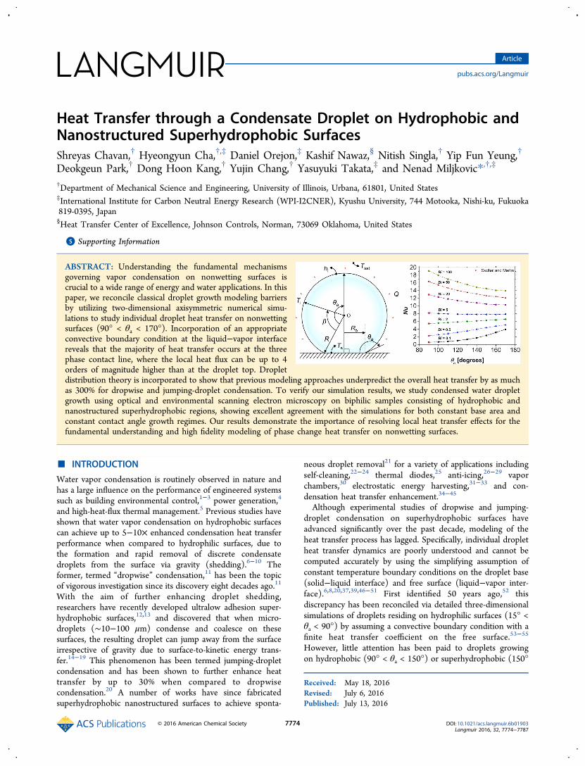
ABSTRACT: Understanding the fundamental mechanismsgoverning vapor condensation on nonwetting surfaces iscrucial to a wide range of energy and water applications. In thispaper, we reconcile classical droplet growth modeling barriersby utilizing two-dimensional axisymmetric numerical simu-lations to study individual droplet heat transfer on nonwettingsurfaces (90° < θa < 170°). Incorporation of an appropriateconvective boundary condition at the liquid−vapor interfacereveals that the majority of heat transfer occurs at the threephase contact line, where the local heat flux can be up to 4orders of magnitude higher than at the droplet top. Dropletdistribution theory is incorporated to show that previous modeling approaches underpredict the overall heat transfer by as muchas 300% for dropwise and jumping-droplet condensation. To verify our simulation results, we study condensed water dropletgrowth using optical and environmental scanning electron microscopy on biphilic samples consisting of hydrophobic andnanostructured superhydrophobic regions, showing excellent agreement with the simulations for both constant base area andconstant contact angle growth regimes. Our results demonstrate the importance of resolving local heat transfer effects for thefundamental understanding and high fidelity modeling of phase change heat transfer on nonwetting surfaces.
■ INTRODUCTION
Water vapor condensation is routinely observed in nature andhas a large influence on the performance of engineered systemssuch as building environmental control,1−3 power generation,4
and high-heat-flux thermal management.5 Previous studies haveshown that water vapor condensation on hydrophobic surfacescan achieve up to 5−10× enhanced condensation heat transferperformance when compared to hydrophilic surfaces, due tothe formation and rapid removal of discrete condensatedroplets from the surface via gravity (shedding).6−10 Theformer, termed “dropwise” condensation,11 has been the topicof vigorous investigation since its discovery eight decades ago.11
With the aim of further enhancing droplet shedding,researchers have recently developed ultralow adhesion super-hydrophobic surfaces,12,13 and discovered that when micro-droplets (∼10−100 μm) condense and coalesce on thesesurfaces, the resulting droplet can jump away from the surfaceirrespective of gravity due to surface-to-kinetic energy trans-fer.14−19 This phenomenon has been termed jumping-dropletcondensation and has been shown to further enhance heattransfer by up to 30% when compared to dropwisecondensation.20 A number of works have since fabricatedsuperhydrophobic nanostructured surfaces to achieve sponta-
neous droplet removal21 for a variety of applications includingself-cleaning,22−24 thermal diodes,25 anti-icing,26−29 vaporchambers,30 electrostatic energy harvesting,31−33 and con-densation heat transfer enhancement.34−45
Although experimental studies of dropwise and jumping-droplet condensation on superhydrophobic surfaces haveadvanced significantly over the past decade, modeling of theheat transfer process has lagged. Specifically, individual dropletheat transfer dynamics are poorly understood and cannot becomputed accurately by using the simplifying assumption ofconstant temperature boundary conditions on the droplet base(solid−liquid interface) and free surface (liquid−vapor inter-face).6,8,20,37,39,46−51 First identified 50 years ago,52 thisdiscrepancy has been reconciled via detailed three-dimensionalsimulations of droplets residing on hydrophilic surfaces (15° <θa < 90°) by assuming a convective boundary condition with afinite heat transfer coefficient on the free surface.53−55
However, little attention has been paid to droplets growingon hydrophobic (90° < θa < 150°) or superhydrophobic (150°
Received: May 18, 2016Revised: July 6, 2016Published: July 13, 2016
Article
pubs.acs.org/Langmuir
© 2016 American Chemical Society 7774 DOI: 10.1021/acs.langmuir.6b01903Langmuir 2016, 32, 7774−7787

< θa < 180°) surfaces from a simulation standpoint. Given therecent discovery and the great potential of jumping-dropletcondensation, work is needed to study droplet condensationheat transfer on superhydrophobic substrates having advancingcontact angles greater than 90°.In this work, we develop a two-dimensional (2D)
axisymmetric numerical simulation of the individual dropletheat transfer on hydrophobic and superhydrophobic surfaces tostudy droplets of arbitrary contact angle (90° < θa < 170°). Thelocal droplet heat flux and temperature are computed andexpressions for the droplet Nusselt number as a function of theBiot number and apparent advancing contact angle arepresented, showing excellent agreement with the previouslyderived analytical solution for hemispherical droplets (θa =90°). Using our simulation results, we demonstrate that themajority of the heat transfer during condensation on super-hydrophobic surfaces occurs at the three-phase contact line,and that local heat transfer and temperature effects must beconsidered when computing condensation heat transferthrough droplets residing on superhydrophobic surfaces dueto their large interfacial temperature variation and minimalcontact area with the substrate. To verify our simulations, weperformed optical microscopy studies of water vaporcondensation in the presence of noncondensable gases onmacroscopically biphilic copper samples having simultaneoushydrophobic (θa ≈ 140°) and superhydrophobic (θa ≈ 170°)droplet morphologies. To elucidate the effects of non-condensables, we also performed environmental scanningelectron microscopy (ESEM) of water vapor condensation onsuperhydrophobic (θa ≈ 170°) and hydrophobic (θa ≈ 120°)surfaces. The numerical simulations showed excellent agree-ment with the experimental results under identical super-saturations and for both constant basal area and constantcontact angle growth regimes. The outcomes of this workelucidate the heat transfer physics governing individual dropletgrowth during vapor condensation on both hydrophobic andsuperhydrophobic surfaces that can be extended to the study ofdroplet-basal contact resistance on microstructured surfaces,droplet evaporation, and droplet freezing processes.
■ RESULTS AND DISCUSSIONModel Development. To study the individual droplet heat
transfer process of noncoalescing droplets, a 2D axisymmetricnumerical model based on the finite element method was usedto solve the heat equation through a single droplet (seeSupporting Information, section S1). Although the droplet heattransfer process during condensation is exceedingly complex,some simplifying assumptions are possible from realizing thatmost of the heat is transferred through droplets of diameter lessthan 100 μm.37,56 For such small droplets the influence ofgravity on the droplet shape is negligible and a spherical-segment geometry may be assumed (Figure 1). In addition,Marangoni and buoyant convection are neglected since thedroplets are sufficiently small so that conduction is thedominant mode of heat transfer.57,58 Furthermore, the heattransfer and droplet growth are quasi-steady processesgoverned by the steady heat-conduction equation, ensuringthat an analytic formulation can be completed with variousboundary conditions.53 To reconcile the discontinuityassociated with a constant free surface temperature, we assumea constant heat transfer coefficient boundary condition at theliquid−vapor interface (hi), and a constant temperature (Ts)boundary condition at the solid−liquid interface (Figure 1).
Thus, there is no sudden temperature jump (discontinuity)across the three phase contact line, and the temperature willchange gradually along the liquid−vapor interface. The liquid−vapor interface heat transfer coefficient is given by theinterfacial condensation heat transfer coefficient, hi:
59
αα π ν
=−
hR T
h
T2
21
2ig sat
fg2
g sat (1)
where Rg is the specific gas constant and νg is the water vaporspecific volume, Tsat is the water vapor saturation temperature,and hfg is the latent heat of condensation phase change. Since itis widely accepted that hi is independent of the interfacelocation, we henceforth consider hi as constant along theliquid−vapor interface.52 The condensation coefficient α is theratio of vapor molecules that will be captured by the liquidphase to the total number of vapor molecules reaching theliquid surface (ranging from 0 to 1). To study the effect ofcondensation coefficient on heat transfer, the model wassimulated for different values of α (0.01, 0.04, and 1),representing both contaminated (α = 0.01) and clean (α =1) environments.52
The condensate droplet is assumed to have a constantapparent advancing contact angle (θa). This assumption placesconstraints on the maximum structure length scale beneath thedroplet since only nanostructured surfaces result in both (1)droplets with constant contact angle at an early stage of dropletgrowth (R ∼ 100 nm)15,37 and (2) negligible thermal resistancebeneath the droplet.39 Hence, this assumption is well suited fordroplets having radii bigger than 100 nm on smoothhydrophobic surfaces (90° < θa < 125°),10 as well asnanostructured superhydrophobic surfaces.20,37
Nondimensional analysis of the simulation parametersreveals three fundamental dimensionless groups governing thedroplet heat transfer behavior (see Supporting Information,section S2). The individual droplet heat transfer, characterizedby the droplet Nusselt number (Nu), is a function of the Biotnumber (Bi) and apparent advancing contact angle (θa); that is,
Figure 1. Schematic of the simulation domain showing a condensatedroplet with radius (R), base radius (Rb), and advancing contact angle(θa). The boundary conditions are (1) constant base (solid−liquidinterface) temperature (Ts), (2) constant vapor temperature (Tsat),and (3) constant interfacial heat transfer coefficient (hi) at the freesurface (liquid−vapor interface). The steady state heat conductionequation (▽2T = 0) governs the heat transfer inside the 3D droplet,and Marangoni and buoyant convection are negligible due to the smalldroplet radii considered in these simulations.
Langmuir Article
DOI: 10.1021/acs.langmuir.6b01903Langmuir 2016, 32, 7774−7787
7775

Nu = f(Bi,θa). Here, the Nusselt and Biot numbers are definedin terms of the droplet base radius (Rb) as
53
=Bih Rki b
w (2)
=−
NuQ
k R T T( )w b sat s (3)
where Q is the total heat transfer through the droplet and kw isthe droplet thermal conductivity. The Biot number Bi is theratio of thermal resistances inside of and at the surface of abody, while the Nusselt number Nu is defined as the ratio ofconvective to conductive heat transfer. To access a wideparameter space, numerical simulations were conducted for Ts= 90 °C, Tsat = 100 °C, 90° < θa < 170°, and 0.1 < Bi < 105
(corresponding to droplet base radii: 3.19 nm < Rb < 3.19 mmfor α = 1). It is important to note that since the majority of heatis transferred through small droplets (<100 μm) duringcondensation we limit our analysis to Bi ≤ 100 (α = 1) forwhich the droplet radius falls below the capillary length of waterat standard laboratory conditions (∼2 mm). Furthermore,although provided here, analysis results for droplets havingboth high Bi and θa should be used with caution since theresultant droplet may be physically much larger than thedroplet capillary number and undergo breakup in real life priorto reaching such a large size.
Model Results. Figure 2 shows the liquid−vapor interfacialtemperature (Ti) and heat flux (q″) as a function of interfacelocation (β) from the three phase contact line for (a, b) θa =120° and (c, d) θa = 170°. Droplets having low Bi (Bi → 0.1, Rb
→ 157 nm for α = 0.04) showed smaller temperature gradientsin the vicinity of the three phase contact line, that is, β < 5°,when compared to droplets with high Bi (Bi → 100, Rb → 157μm for α = 0.04). A small condensation coefficient, α = 0.04was used for these simulations to better display of gradient of Ti
and q″ for a given Bi. The efficient heat transfer of smalldroplets results in higher vapor-to-free-surface temperaturedifference (Tsat − Ti) due to the low conduction pathwaythough the droplet itself (Qconduction = Qinterface ≈ hi(Tsat − Ti)),and hence lower temperature gradients. The interfacial heat flux(Figure 2b,d)) is very nonuniform and peaks at the three-phasecontact line due to the efficient heat path from the liquid−vapor interface to the droplet base. Small droplets (Bi → 0.1)exhibited higher local heat fluxes when compared to their largercounterparts (Bi → 100) due to the low droplet conductionresistance, meanwhile larger droplets having elevated contactangles (θa → 180°) showed significant heat flux degradationdue to the poor heat transfer characteristics caused by thelimited droplet basal area (Figure 2d). The results show thatthe local heat flux can vary as much as 4 orders of magnitudefrom the three-phase contact line to the droplet top, indicatingthe importance of resolving the local heat transfer in order toobtain high fidelity results. It is worth noting that Bi is defined
Figure 2. (a) Droplet interface temperature (Ti) and (b) local heat flux (q″) as a function of interface location (β) for different Biot numbers (0.1 <Bi < 100, corresponding to 157 nm < Rb < 157 μm, for α = 0.04), and advancing contact angles (θa) of (a,b) 120° and (c,d) 170°. A lowcondensation coefficient, α = 0.04 was used for these simulations to better display the gradient of Ti and q″ along the condensing interface for a givenBi. Inset of panels a and c: Droplet cross sectional temperature profile for droplets with Bi = 0.1 (droplets not to scale). Small droplets (Bi → 0.1)with low advancing contact angles (θa → 90°) have lower temperature gradients in the vicinity of the three phase contact line (β < 5°) whencompared to large droplets (Bi → 100) with high advancing contact angles (θa → 180°). Furthermore, all droplets show elevated heat fluxes at thethree-phase contact line (b,d) due to the low path for heat to travel from the liquid−vapor interface to the droplet base, suggesting the importance ofunderstanding local heat transfer in order to obtain high fidelity results. The droplet curvature resistance (Kelvin effect) is not taken into account forthese simulations.
Langmuir Article
DOI: 10.1021/acs.langmuir.6b01903Langmuir 2016, 32, 7774−7787
7776
based on the droplet base radius Rb (eq 2), rather than thedroplet radius R, hence droplets with identical Bi and differingθa have different droplet radii and heat transfer. It is alsoimportant to note that for the same droplet volume, theindividual droplet heat transfer for low θa is greater than forhigh θa. A comparison of the droplet heat transfer as a functionof θa for a fixed droplet volume is included in Figure S5 of theSupporting Information.To further quantify the droplet heat transfer, the simulation
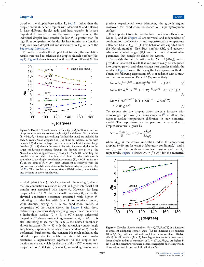
results were used to calculate the droplet Nusselt number (Nu,eq 3). Figure 3 shows Nu as a function of θa for different Bi. For
small droplets (Bi < 5), Nu increases with increasing θa due tothe low conduction resistance as well as higher interfacial heattransfer area associated with higher θa. However, for largedroplets (Bi > 5), Nu decreases with increasing θa due to theelevated conduction resistance associated with higher θa,indicating that droplets with Bi < 5 are interface limited,while droplets having Bi > 5 are conduction limited. Acomparison of the results shown in Figure 3 with thoseobtained by a previous study analyzing droplet heat transfer ona hydrophilic surface (0 < θa < 90°) using differentialinequalities,53 shows excellent agreement at θa = 90°. It isalso interesting to see that for Bi ≈ 5, the Nusselt number isalmost invariant (Nu ≈ 8) with the advancing contact angleand, hence, experiments which are independent of θa can beperformed. Furthermore, the constant Nu result indicates thecritical droplet size for which the interfacial heat transferresistance is approximately equivalent to the droplet con-duction resistance, which for the case of θa ≈ 170° equates to adroplet size of R ≈ 1 μm (for α = 1), in good agreement with
previous experimental work identifying the growth regimecrossover for conduction resistance on superhydrophobicsurfaces.37
It is important to note that the heat transfer results relatingNu to θa and Bi (Figure 3) are universal and independent ofcondensation coefficient (α) and vapor-to-surface temperaturedifference (ΔT = Tsat − Ts). This behavior was expected sincethe Nusselt number (Nu), Biot number (Bi), and apparentadvancing contact angle (θa) are the three dimensionlessparameters that completely define the system.To provide the best fit estimate for Nu = f (Bi,θa), and to
provide an analytical result that can more easily be integratedinto droplet growth and phase change heat transfer models, theresults of Figure 3 were fitted using the least-squares method toobtain the following expressions (θa is in radians) with a meanand maximum error of 4% and 23%, respectively:
θ θ= + ≤−Nu Bi Bi Bi3 0.007 0.5a0.65 0.83
a5.1 0.23
(4)
θ θ= + < ≤− −Nu Bi Bi Bi0.29 3.33 0.5 2a2.24 0.17
a0.3 0.72
(5)
= + −
< ≤
θ−Nu e Bi Bi
Bi
5.76 ln(1 5 2.79 )
2 10
0.28 0.82 0.83
5
a0.68
(6)
To account for the droplet vapor pressure increase withdecreasing droplet size (increasing curvature)60 we altered thevapor-to-surface temperature difference in our numericalmodel. The vapor-to-surface temperature decrease due todroplet curvature is given by
σρ
Δ = − =TR
RT T
TRh
( )2
cmin
sat ssat
fg w (7)
where Rmin is the critical nucleation radius for condensingdroplets (∼10 nm for water at laboratory conditions),60 and σand ρw are the condensate surface tension and density,respectively. Figure 4 shows Nu = f(Bi,θa) for the numerical
Figure 3. Droplet Nusselt number (Nu = Q/(kwRbΔT)) as a functionof apparent advancing contact angle (θa) for different Biot numbers(Bi = hiRb/kw). Least squares fitting (dashed-dot lines) are included foreach Bi result. Small droplets (Bi < 5) show an increase in Nu withincreased θa due to the larger interfacial area for heat transfer. Largedroplets (Bi > 5) show a decrease in Nu with increased θa due to thelarger conduction resistance through the droplet. For Bi ≈ 5, theNusselt number is approximately constant (Nu ≈ 8), indicating thedroplet size for which the interfacial heat transfer resistance isequivalent to the droplet conduction resistance (Rb ≈ 0.16 μm for α =1). In the limit of θa = 90°, exact agreement is observed with theprevious exact analytical solutions of Sadhal and Martin (red asterisks,ref 53). The droplet curvature resistance (Kelvin effect) is not takeninto account in these simulations.
Figure 4. Droplet Nusselt number (Nu = Q/(kwRbΔT)) as a functionof apparent advancing contact angle (θa) for different Biot numbers(Bi = hiRb/kw) with and without droplet curvature resistance (Kelvineffect). Small droplets (Bi < 5) have higher temperature drop due tolower droplet radius of curvature, ΔTc = 2Tsatσ/Rhfgρw. At higher Bi(Bi > 5), the curvature resistance becomes negligible due to larger radiiof curvature, and hence has little effect on Nu.
Langmuir Article
DOI: 10.1021/acs.langmuir.6b01903Langmuir 2016, 32, 7774−7787
7777

simulation with and without the curvature resistance included.As observed from Figure 4, and Equation 7, the curvatureresistance decreases as droplet size increases and becomesnegligible for Bi ≥ 5 (Rb ≈ 160 nm for α = 1), hence itsinclusion in the exact numerical simulation resulted innegligible changes in heat transfer behavior.To compare the results of our numerical simulation to the
state-of-the art (SoA) analytical solutions,39,47 we define theoverall droplet thermal resistance as Rt = (Tsat − Ts)/Q, where(Tsat − Ts) = 10 °C and Q is obtained from numericalsimulation and analytical model. The droplet thermal resistanceincludes the interfacial heat transfer resistance due to thedifficulty of isolating the droplet conduction resistance(nonconstant free-surface temperature). Figure 5 shows the
numerical and analytical overall droplet thermal resistance as afunction of θa for different Bi. Both the numerical and analyticalsolutions show excellent agreement at low Bi (Bi < 5) howeverthe solutions deviate significantly as Bi increases (Bi > 5) due tothe higher error associated with the analytical method for largerdroplets. At low droplet radii (Bi < 5), the interfacial heattransfer resistance dominates both solutions, hence the goodagreement observed. As the droplet radius increases (Bi > 5),the droplet growth becomes conduction limited and thediscrepancy between the two methods becomes apparent. Froma physical standpoint, the smaller thermal resistance of thenumerical solution stems from its ability to capture local heattransfer effects at the three phase contact line. As shown inFigure 2, the three phase contact line acts as a heat transfer
channel during condensation of large droplets (Bi > 5) due tothe low heat diffusion distance. Currently used analyticalapproaches using conduction shape factor solutions cannotreconcile these details, resulting in low-fidelity results.To study the overall steady-state condensation heat flux, we
combined the simulation results with droplet distributiontheory to account for the fraction of droplets on the surface of agiven radius R for surfaces undergoing gravitation shedding andjumping. For small droplets (R ≤ Re), the size distribution n(R)is determined by47
π=
−−
×++
+
−⎜ ⎟⎛⎝
⎞⎠n R
R RRR
R R RR R
A R AA R A
B B
( )1
3( )
exp( )
e3
e2/3
e min
min
2 3
2 e 31 2
(8)
where R is the average maximum droplet radius (departureradius), Re is the radius when droplets begin to merge and growby droplet coalescence, Rmin is the critical nucleation radius forcondensing droplets (≈10 nm for water), and A2, A3, B1, and B2are constants associated with droplet growth and sweeping (fordetailed model explanation, see Supporting Information,section S3). For large droplets growing due to coalescence(R ≥ Re), the droplet distribution N(R) is determined from7
π=
−⎜ ⎟⎛⎝
⎞⎠N R
R RRR
( )1
3 2
2/3
(9)
where both n(R) and N(R) have the units of m−3. The totalsurface steady state condensation heat flux (q″) is obtained byincorporating the individual droplet heat transfer rate obtainedfrom simulations (eq 4 to 6), with the droplet size distributions(eq 8 and 9):
∫ ∫″ = +
q Q R n R R Q R N R R( ) ( ) d ( ) ( ) dR
R
R
R
min
e
e (10)
Figure 6 shows the steady-state condensation heat flux as afunction of θa for dropwise and jumping-droplet removalmechanisms. For both the numerical and analytical solutions,increasing θa results in decreased heat transfer performance dueto the formation of droplets which are more spherical and havehigher conduction thermal resistances through them. Althoughexperimentally, surfaces having elevated contact anglesnecessitate greater nonwetting and smaller contact anglehysteresis, the hysteresis was kept constant in these simulationsto simplify the model. The jumping-droplet condensation heattransfer coefficient was ∼40% higher than that of dropwisecondensation, in excellent agreement with previous exper-imental studies.61 Interestingly, a significant difference in thecondensation heat flux can be observed between the analyticaland numerical solutions. For dropwise condensation, thedifference is as large as 300%, which stems from the inabilityof the analytical solution to capture the local heat transferbehavior at the three phase contact line. Furthermore, dropwisecondensation is typified by the formation of large droplets (∼2mm for water) prior to shedding, resulting in a considerablefraction of droplets having Bi > 5, where the analytical andnumerical models have been shown to diverge (Figure 5).Conversely, the jumping droplet condensation results had arelatively smaller deviation between the analytical andnumerical results due to jumping-droplet condensation havinga large population of small microdroplets (∼10 μm) with Bi <5, where the growth is interface limited and conduction
Figure 5. Droplet thermal resistance (Rt = (Tsat − Ts)/Q) as afunction of apparent advancing contact angle (θa) for different dropletBiot number (Bi = hiRb/kw) and condensation coefficient α = 1. Thethermal resistance is from the vapor (Tsat) to the surface (Ts) andcombines both the interfacial heat transfer resistance and theconduction resistance through the droplet. The combination ofinterfacial and conduction resistances was necessary due to thenonuniform free surface temperature (Ti). Both analytical (ref 47) andnumerical (our work) values are provided. The analytical solutionassumes a constant free-surface temperature with an approximateshape factor to compute the droplet thermal resistance:Rt,analytical = 1/(2πR2hi (1−cos θa) + θa/(4πRk sin θa)). The analytical and numericalresults show good agreement for small droplets (Bi < 5) due to thenegligible droplet conduction resistance in this regime. However, asdroplets grow larger (Bi > 5), the discrepancy between the numericaland analytical results increases due to the growing influence of dropletconduction on droplet growth and heat transfer.
Langmuir Article
DOI: 10.1021/acs.langmuir.6b01903Langmuir 2016, 32, 7774−7787
7778
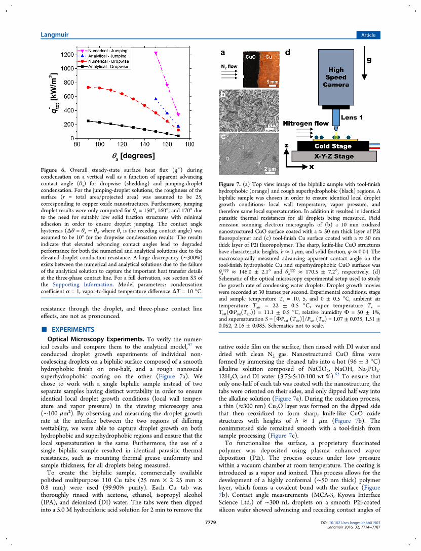
resistance through the droplet, and three-phase contact lineeffects, are not as pronounced.
■ EXPERIMENTSOptical Microscopy Experiments. To verify the numer-
ical results and compare them to the analytical model,47 weconducted droplet growth experiments of individual non-coalescing droplets on a biphilic surface composed of a smoothhydrophobic finish on one-half, and a rough nanoscalesuperhydrophobic coating on the other (Figure 7a). Wechose to work with a single biphilic sample instead of twoseparate samples having distinct wettability in order to ensureidentical local droplet growth conditions (local wall temper-ature and vapor pressure) in the viewing microscopy area(∼100 μm2). By observing and measuring the droplet growthrate at the interface between the two regions of differingwettability, we were able to capture droplet growth on bothhydrophobic and superhydrophobic regions and ensure that thelocal supersaturation is the same. Furthermore, the use of asingle biphilic sample resulted in identical parasitic thermalresistances, such as mounting thermal grease uniformity andsample thickness, for all droplets being measured.To create the biphilic sample, commercially available
polished multipurpose 110 Cu tabs (25 mm × 2 25 mm ×0.8 mm) were used (99.90% purity). Each Cu tab wasthoroughly rinsed with acetone, ethanol, isopropyl alcohol(IPA), and deionized (DI) water. The tabs were then dippedinto a 5.0 M hydrochloric acid solution for 2 min to remove the
native oxide film on the surface, then rinsed with DI water anddried with clean N2 gas. Nanostructured CuO films wereformed by immersing the cleaned tabs into a hot (96 ± 3 °C)alkaline solution composed of NaClO2, NaOH, Na3PO4·12H2O, and DI water (3.75:5:10:100 wt %).62 To ensure thatonly one-half of each tab was coated with the nanostructure, thetabs were oriented on their sides, and only dipped half way intothe alkaline solution (Figure 7a). During the oxidation process,a thin (≈300 nm) Cu2O layer was formed on the dipped sidethat then reoxidized to form sharp, knife-like CuO oxidestructures with heights of h ≈ 1 μm (Figure 7b). Thenonimmersed side remained smooth with a tool-finish fromsample processing (Figure 7c).To functionalize the surface, a proprietary fluorinated
polymer was deposited using plasma enhanced vapordeposition (P2i). The process occurs under low pressurewithin a vacuum chamber at room temperature. The coating isintroduced as a vapor and ionized. This process allows for thedevelopment of a highly conformal (∼50 nm thick) polymerlayer, which forms a covalent bond with the surface (Figure7b). Contact angle measurements (MCA-3, Kyowa InterfaceScience Ltd.) of ∼300 nL droplets on a smooth P2i-coatedsilicon wafer showed advancing and receding contact angles of
Figure 6. Overall steady-state surface heat flux (q″) duringcondensation on a vertical wall as a function of apparent advancingcontact angle (θa) for dropwise (shedding) and jumping-dropletcondensation. For the jumping-droplet solutions, the roughness of thesurface (r = total area/projected area) was assumed to be 25,corresponding to copper oxide nanostructures. Furthermore, jumpingdroplet results were only computed for θa = 150°, 160°, and 170° dueto the need for suitably low solid fraction structures with minimaladhesion in order to ensure droplet jumping. The contact anglehysteresis (Δθ = θa − θr, where θr is the receding contact angle) wasassumed to be 10° for the dropwise condensation results. The resultsindicate that elevated advancing contact angles lead to degradedperformance for both the numerical and analytical solutions due to theelevated droplet conduction resistance. A large discrepancy (∼300%)exists between the numerical and analytical solutions due to the failureof the analytical solution to capture the important heat transfer detailsat the three-phase contact line. For a full derivation, see section S3 ofthe Supporting Information. Model parameters: condensationcoefficient α = 1, vapor-to-liquid temperature difference ΔT = 10 °C.
Figure 7. (a) Top view image of the biphilic sample with tool-finishhydrophobic (orange) and rough superhydrophobic (black) regions. Abiphilic sample was chosen in order to ensure identical local dropletgrowth conditions: local wall temperature, vapor pressure, andtherefore same local supersaturation. In addition it resulted in identicalparasitic thermal resistances for all droplets being measured. Fieldemission scanning electron micrographs of (b) a 10 min oxidizednanostructured CuO surface coated with a ≈ 50 nm thick layer of P2ifluoropolymer and (c) tool-finish Cu surface coated with a ≈ 50 nmthick layer of P2i fluoropolymer. The sharp, knife-like CuO structureshave characteristic heights, h ≈ 1 μm, and solid fraction, φ ≈ 0.04. Themacroscopically measured advancing apparent contact angle on thetool-finish hydrophobic Cu and superhydrophobic CuO surfaces wasθa
app ≈ 146.0 ± 2.1° and θaapp ≈ 170.5 ± 7.2°, respectively. (d)
Schematic of the optical microscopy experimental setup used to studythe growth rate of condensing water droplets. Droplet growth movieswere recorded at 30 frames per second. Experimental conditions: stageand sample temperature Ts = 10, 5, and 0 ± 0.5 °C, ambient airtemperature Tair = 22 ± 0.5 °C, vapor temperature Tv =Tsat(ΦPsat(Tair)) = 11.1 ± 0.5 °C, relative humidity Φ = 50 ± 1%,and supersaturation S = [ΦPsat (Tair)]/Psat (Tw) = 1.07 ± 0.035, 1.51 ±0.052, 2.16 ± 0.085. Schematics not to scale.
Langmuir Article
DOI: 10.1021/acs.langmuir.6b01903Langmuir 2016, 32, 7774−7787
7779
θa = 125.4 ± 2.9° and θr = 115.1 ± 3.8°, respectively. Using thevalues of the advancing contact angles on the rough (θa
app ≈170.5 ± 7.2°) and smooth (θa = 125.4 ± 2.9°) P2i surfaces, weestimated the effective solid fraction of the CuO surface to be φ= (cos θa
app + 1)/(cos θa + 1) ≈ 0.04. The functionalization ofthe whole surface resulted in ideal biphilic behavior with thetool-finish hydrophobic (Figure 7c) and rough superhydro-phobic (Figure 7b) regions showing advancing contact anglesof θa ≈ 146.0 ± 2.1° and θa
app ≈ 170.5 ± 7.2°, respectively.Droplet growth behavior was studied using a custom built
top-view optical light microscopy setup shown diagrammati-cally in Figure 7d and substantially similar to the one describedin ref 63. Briefly, samples were placed horizontally on the coldstage (Instec, TP104SC-mK2000A) with a thin film of waterunderneath in order to provide good thermal communicationbetween the sample and stage. The cold stage was cooled to thetest temperatures of Ts = 10, 5, and 0 ± 0.5 °C in a laboratoryenvironment having air temperature, Tair = 22 ± 0.5 °C, andrelative humidity (RH), Φ = 50 ± 1% (Roscid Technologies,RO120). Video recordings were performed at frame rates of 30frames/s with a high speed camera (Phantom, V711, VisionResearch) attached to an upright microscope (Eclipse LV100,Nikon) (Figure 7d). Top view imaging was performed with a20X (TU Plan Fluor EPI, Nikon) objective (Figure 7d). Forthe 20X, lens, the working distance was measured to be 5 ± 0.5mm. Illumination was supplied by an LED light source (SOLASM II Light Engine, Lumencor). The LED light source wasspecifically chosen for its high-intensity and low powerconsumption (2.5 W) in order to minimize heat generation
at the surface due to light absorption and minimize its influenceon the droplet growth rates during condensation. Furthermore,by manually reducing the condenser aperture diaphragmopening size and increasing the camera exposure time, wewere able to minimize the amount of light energy needed forillumination and hence minimize local heating effects duringcondensation experiments.64
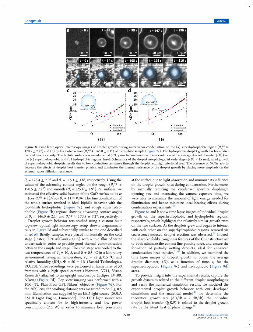
Figure 8a and b show time lapse images of individual dropletgrowth on the superhydrophobic and hydrophobic regions,respectively, which highlights the relatively similar growth rateson the two surfaces. As the droplets grew and began to interactwith each other on the superhydrophobic regions, removal viacoalescence-induced droplet ejection was observed.14 Indeed,the sharp knife-like roughness features of the CuO structure actto both minimize the contact line pinning force, and ensure theformation of partially wetting droplets, ideal for enhancedcondensation heat transfer.61,65 In addition, we examined thetime lapse images of droplet growth to obtain the averagedroplet diameter, ⟨D⟩, as a function of time, t, for thesuperhydrophobic (Figure 8c) and hydrophobic (Figure 8d)areas.To provide insight into the experimental results, capture the
growth dynamics related to the different droplet morphologies,and verify the numerical simulation results, we modeled theexperimental droplet growth behavior with our developedsimulations and the analytical model.47 To determine thetheoretical growth rate (dD/dt = 2 dR/dt), the individualdroplet heat transfer Q(R,θ) is related to the droplet growthrate by the latent heat of phase change39
Figure 8. Time lapse optical microscopy images of droplet growth during water vapor condensation on the (a) superhydrophobic region (θaapp ≈
170.5 ± 7.2°) and (b) hydrophobic region (θaapp ≈ 146.0 ± 2.1°) of the biphilic sample (Figure 7a). The hydrophobic droplet growth has been false-
colored blue for clarity. The biphilic surface was maintained at 5 °C prior to condensation. Time evolution of the average droplet diameter (⟨D⟩) onthe (c) superhydrophobic and (d) hydrophobic regions. Inset: Schematics of the droplet morphology. At early stages (⟨D⟩ < 15 μm), rapid growthof superhydrophobic droplets results due to low conduction resistance through the droplet and high interfacial area. The presence of NCGs acts todecrease the effects of droplet heat transfer physics, and dominates the thermal resistance of the droplet growth by placing more emphasis on theexternal vapor diffusion resistance.
Langmuir Article
DOI: 10.1021/acs.langmuir.6b01903Langmuir 2016, 32, 7774−7787
7780

θ
ρ
π ρ θ θ
=
=
= − +
Q R mh
hVt
ht
R
( , )
dd
3dd
[(1 cos ) (2 cos ) ]
fg
w fg
w fg2 3
(11)
Differentiating the terms in squared brackets on the right-hand-side of eq 11, we obtain an explicit term for dR/dt
θ πρ θ θ θ
θ θ
= −
+ − +
{}
Q R h RRt R
R( , )dd
(1 cos ) sindd
(1 cos ) (2 cos )
w fg2 2 2
2
(12)
The individual droplet heat transfer, Q(R,θ) = f(Ts,α,Psat), wascomputed using our simulation (black solid line in Figure 8c,d)and the analytical model (blue line in Figure 8c,d). When awater droplet nucleates and grows on the superhydrophobicsurface, a varying contact angle is observed initially for D < 6−8μm because of locally pinned contact lines at the droplet base.36
Thus, in order to simulate the growth of droplets on thesuperhydrophobic surface (Figure 8a), we used a bandapproximation for the advancing contact angle, with θa =150° for D ≤ 7 μm, θa = 160° for 7 μm < D ≤ 14 μm, and θa =170° for D > 14 μm, in agreement with previous well-characterized droplet growth studies during condensation onsuperhydrophobic CuO.36 For droplets growing on thehydrophobic surface, droplet contact angle variation as afunction of droplet diameter was not observed, thus a constantθa = 140° was used for the models.The results of the numerical model (black solid line) are
shown in Figure 8c,d and are in excellent agreement with theexperiments (red circles). The analytical model (blue solid linein Figure 8c,d), however, tends to underestimate theexperimental growth rate due to the lack of taking into accountlocal heat transfer effects at the three-phase contact line. Asobserved in the experiments, the numerical model shows thatfor large droplet diameters (D > 15 μm), droplets growing onthe superhydrophobic surface have slightly lower growth ratesthan a droplet on the hydrophobic surface due to the addedconduction thermal resistance. While at low droplet diameters(D < 15 μm), the growth rate of the superhydrophobic dropletsis faster due to interfacial thermal resistance dominated growth.The model solutions were obtained for surface-to-vaportemperature difference ΔTnumerical = ΔTanalytical = 0.0018 °C,where ΔT was chosen on the basis of the best fit between thenumerical model and experimental growth rate data. Theexperimental surface-to-vapor temperature difference, ΔTexp =Tsat (ΦPsat (Tair)) − Ts = 6.1 ± 0.58 °C, was three orders ofmagnitude larger than the numerical temperature difference.The significant discrepancy between model and experimentscan be attributed to the presence of noncondensable gases(NCGs). The condensation of water vapor acts to leave behindNCGs (air) that blanket the surface and act as a diffusionbarrier for water vapor.66−68 The counter diffusion of watervapor to the surface, coupled with the diffusion of NCGs awayfrom the surface, acts to significantly deteriorate thecondensation heat transfer process, and hence decrease theeffective surface-to-vapor temperature difference. Interestingly,previous analysis of filmwise condensation in the presence ofNCGs showed temperature drops of similar orders ofmagnitude as observed in these experiments, with ∼2 °C
happening in the vapor diffusion layer, and ∼0.01 °C occurringin the condensate film.69
As a secondary artifact, the presence of NCGs can beobserved through the relatively large error bars in the dropletgrowth data (Figure 8c,d). Significant variability in individualdroplet growth was observed based on the location of dropletsrelative to one another, with isolated droplets growing fasterthan droplets residing close to many neighbors. The dropletgrowth variability can also be attributed to the presence ofNCGs, formation of vapor depletion layers, and concentrationboundary layer overlap from droplet-to-droplet.70−72
To gain further insight, we compared the experimentalresults with the power law exponent model.72 When dropletdimensions are larger than the surface pattern length scales(⟨D⟩ > 1 μm, as observed here), droplets grow as breath figureson a surface with an expected average droplet diameter of ⟨D⟩= Atμ, where μ, the power law exponent, ranges from 0 to 1depending on the droplet, substrate dimensions, and growthlimiting conditions. In these experiments, due to the presencesof NCGs, we expect vapor diffusion limitations to dominatedroplet growth dynamics. To determine if the vapor diffusionboundary layers of neighboring water droplets overlap, wecalculated the boundary layer length scale given by73
ρε
= Γ−Rt
DnR
dd 12 w
1 0(13)
where D12 is mutual diffusion coefficient of water in air, ρw isthe number density of water, Γ is a geometrical factor related tothe contact angle θ, n0 is the average concentration ofmonomers established in the vapor medium, and ε is thelength of vapor diffusion boundary layer. For the dropletgrowth experiments conducted here, the calculated vapordiffusion boundary layer thickness was greater than 10 mm forall cases (all droplet sizes on the superhydrophobic andhydrophobic regions of the biphilic surface). From exper-imental observations, the distance between neighboringdroplets was found to be on the order of ∼100 μm. Thus,for adjacent water droplets the vapor diffusion boundary layersoverlap.In the overlapping vapor diffusion boundary layer regime, a
2-D concentration gradient forms, whose typical length scale isof the order of R. Then the droplet grows as72,74
π π∼ ∼ ⎜ ⎟⎛⎝
⎞⎠
Vt
RRt
RR
Ddd
4dd
212
12 (14)
where, dV/dt is the water droplet growth rate. Rearranging eq14 the following relationship D ∼ 2R ∼ t1/3 (μ = 0.3) is foundfor time scales when overlapping of the diffusion boundarylayers dominates and a macroscale NCG layer blankets thesurface.Interestingly, the experimental results of Figures 8c,d agree
remarkably well with the scaling analysis, revealing that thedroplet power law is obeyed by both superhydrophobic andhydrophobic surfaces with μSHP = 0.3, μH = 0.3 at early timescales. The power law results reinforce the critical importancethat NCGs play in the dynamics of droplet growth and helpclarify the similar growth rates and low model temperaturedifferences needed to match the simulations to the experiments.Fitting of ΔT for the other experimental cases having Ts =
10, 5, and 0 °C yielded ΔT = 0.0015, 0.0018, and 0.0025 °C,respectively, in agreement with the fact that NCGs act todominate the vapor and heat transport in these experiments. Itis important to note that for all experiments, fitting with the
Langmuir Article
DOI: 10.1021/acs.langmuir.6b01903Langmuir 2016, 32, 7774−7787
7781

same value of ΔT for both superhydrophobic and hydrophobicdroplet growth yielded the best numerical model fit to theexperimental results. The good agreement is due to ourexperimental ability to maintain the same local conditions(supersaturation) for both surfaces via the biphilic surfacedesign. For additional experimental and model results atdifferent supersaturations, please see Supporting Information,section S4.Perhaps the most interesting aspect of the optical microscopy
studies, in addition to their ability to validate the numericalsimulations, is that droplet jumping was observed on thesuperhydrophobic area for all macroscopically measuredsupersaturations, S = [ΦPsat (Tair)]/Psat (Ts) = 1.07 ± 0.035,1.51 ± 0.052, and 2.16 ± 0.085. Contrary to previous studieson superhydrophobic CuO,61 nucleation mediated flooding dueto saturation of nucleation sites on the surface at S > 1.12 wasnot observed in these experiments. The reason for the elevatedcritical supersaturation is attributed to the presence of NCGs,which were not present in previous studies. The results shownhere point to the need to classify nucleation mediated floodingbased on surface critical heat flux (qcr″ > 8 W/cm2) as opposedto the critical supersaturation (Scr ≈ 1.12), as identicalmacroscopic supersaturations in pure vapor environments andNCG environments yield strikingly different condensation,nucleation, and heat flux behavior.Environmental Scanning Electron Microscopy Experi-
ments. To remove the effects of NCGs, we conducted droplet
growth experiments in an environmental scanning electronmicroscope (ESEM; Versa 3D, FEI) that enabled observationof microscale water droplets at saturation vapor pressures of upto 4 kPa ± 0.2%. The removal of NCGs eliminated thedominant vapor diffusion resistance (not accounted for in thenumerical or analytical model), enabled the principal thermalresistances governing droplet growth to come into play, andhence validate our model with higher accuracy. Prior to theexperiments, a gas scanning electron detector (GSED) and aPeltier stage were mounted inside the ESEM chamber. Eachsample substrate was attached to a 5 mm thick copper sampleholder with carbon conductive tape and then mounted on thePeltier stage to control the temperature of the sample surface.The chamber was closed and pumped down to high vacuummode (<1 mPa) to remove any contaminants or NCGs presentin the chamber. Prior to condensation, the pressure in theESEM chamber was maintained at <100 Pa and the surfacetemperature was set at 0 ± 0.1 °C. To ensure that the surfacetemperature matches the set temperature, the temperature wasmaintained for >10 min prior to condensing. Water vaporpressure in the chamber was gradually increased at 50 Pa/minuntil condensation appeared on the surface at saturationpressures ranging from 630 to 700 Pa. It is important to note,to ensure proper degassing of the water vapor supply, whichconsisted of a Erlenmeyer flask filled with liquid waterconnected via a software controlled valve, the chamber wascycled from condensation to dry out by initiating condensation
Figure 9. Time lapse ESEM images of droplet growth during saturated water vapor condensation on the (a) superhydrophobic Al (θaapp ≈ 170.5 ±
2.5°) and (b) smooth hydrophobic SiO2 (θa ≈ 115.5 ± 4°) samples, respectively. Time evolution of the average droplet diameter (⟨D⟩) on the (c)superhydrophobic and (d) hydrophobic samples. Inset: Schematics of the droplet morphology. The elimination of NCGs from the water vaporamplified the effects of interfacial and droplet conduction resistances. At later stages of growth (⟨D⟩ > 20 μm), the hydrophobic droplet growth rateis much faster than the superhydrophobic due to reduced droplet conduction resistance. For the analytical and numerical models, a vapor-to-surfacetemperature difference of ΔTnumerical = 0.01 °C was used to fit the experimental data. The experimental surface-to-vapor temperature difference,ΔTexp = Tv − Ts = 0.1 ± 0.1 °C, was in excellent agreement with the numerical temperature difference and within the error of the experimentalapparatus. The removal of NCGs eliminated the dominant vapor diffusion resistance (not accounted for in the numerical or analytical model),enabled the principal thermal resistances governing droplet growth to come into play, and hence validate our model with higher accuracy.
Langmuir Article
DOI: 10.1021/acs.langmuir.6b01903Langmuir 2016, 32, 7774−7787
7782
at an elevated pressure (typically 1200 ± 2.4 Pa), condensingfor a full 2 min, reheating the stage to evaporate the condensedwater, and pumping down to 50 ± 0.1 Pa to remove theevaporated vapor. By cycling the evaporation/pump-downcycle 10 times, we ensure that any NCG content in the vaporsupply line has been removed and pumped out of the system.To minimize droplet evaporation as a result of heating by theelectron beam, the voltage and current of the electron beamwere set at 10 kV and <12pA, respectively, and a field of view of120 × 86.5 μm2. For similar ESEM viewing parameters, priorstudies64 have shown negligible beam heating effects at viewingareas <4.6 × 4.3 μm2. Our studies used a larger field of view(120 × 86.5 μm2), making it appropriate to neglect heatingeffects. Droplet growth videos were captured at one frame (768by 556 pixels) every 2 s (dwell time per pixel ∼3 μs).For the ESEM experiments, boehmite nanostructures on
aluminum and smooth silicon wafers functionalized withhydrophobic self-assembled monolayers of HTMS were usedto obtain superhydrophobic and hydrophobic droplet mor-phologies, respectively. The change from copper (∼800 nm) toaluminum-based nanostructures (∼300 nm) does not alter thegrowth dynamics of condensing droplets due to the negligiblethermal resistance of the partially wetted base for both surfaces.Smooth hydrophobic silicon was used instead of tool finishcopper because of our desire to observe droplet growthbehavior on lower advancing contact angle surfaces toinvestigate the robustness of our numerical model.To create superhydrophobic aluminum oxide samples, the
technique given by ref 75 was used. Commercially available Altabs (10 mm × 10 mm × 0.8 mm) were used (99.90% purity).Each Al tab was ultrasonically treated in acetone and then inethanol for 5 min. The cleaned samples were dried in a cleanN2 stream. The specimens were then immersed into hotdeionized water (90 °C) for 1 h, followed by removal andrinsing with room temperature deionized water. This enabledboehmite (Al2O3) formation on the Al surface with sharp,knife-like structures having length scales approaching ∼300 nm.To functional ize the surfaces , heptadecafluoro-
decyltrimethoxy-silane (HTMS) was deposited using vaporphase deposition. Nanostructured Al substrates were placed in acontainer with a vial of 1 mL of HTMS toluene solution (5% v/v). A lid was placed on top to seal the container, and then thecontainer was heated in an atmospheric pressure oven at 80 °Cfor 3 h. This process allows for the development of a highlyconformal coating as the HTMS molecules evaporate fromsolution and redeposit on the aluminum samples. The sametechnique was used to coat HTMS on smooth silicon wafers,which were cleaned with acetone, IPA, DI water, and rinsed inclean N2 prior to functionalization. Contact angle measure-ments of ∼300 nL droplets on a HTMS-coated nanostructuredAl surface showed advancing/receding contact angles of θa
app/θr
app ≈ 170.5 ± 2.5°/155 ± 7°. Smooth HTMS-coated siliconwafers showed advancing/receding contact angles of θa/θr =115.5 ± 4°/107 ± 4°.Figure 9a,b show ESEM time lapse images of individual
droplet growth on the superhydrophobic nanostructuredaluminum surface and on the hydrophobic smooth siliconsurface, which highlights the difference in droplet growth rate.Droplet growth on the surfaces was characterized at a watervapor pressure Pv = 700 ± 1.4 Pa, corresponding to a saturationtemperature of 1.9 ± 0.004 °C, and a substrate temperature Ts= 1.8 ± 0.1 °C. The experimentally obtained droplet diameteras a function of time for superhydrophobic and hydrophobic
morphologies are shown in Figure 9c,d, respectively. Onsuperhydrophobic aluminum, scatter in the droplet growth datawas almost nonexistent, with droplets growing, coalescing,jumping, and regrowing in a self-similar manner for each cycle.In addition, the droplet growth rate of adjacent droplets wasalso identical in nature. The lower variability in growth rate isattributed to the lack of NCGs in the ESEM environment. Thevapor diffusion resistance is much smaller, and hence, dropletgrowth dynamics are limited mainly by interfacial resistance atearly times, and conduction resistance at later times.To provide insight into the ESEM results and verify our
simulations, we modeled the experimental droplet growthbehavior with the numerical and analytical models according toeq 12. The results of the numerical model (black dashed line)are shown in Figure 9c,d and are in excellent agreement withthe experiments. The removal of NCGs acted to accentuate thegrowth rate difference between the two droplet morphologies.As observed in the experiments, the numerical model showsthat for large diameters (D > 20 μm), droplets growing on thesuperhydrophobic surface have lower growth rates (d⟨D⟩/dt =0.06 μm/s) than droplets on the hydrophobic surface (d⟨D⟩/dt= 0.2 μm/s) due to the added conduction thermal resistance.While at low diameters (D < 20 μm), the growth rate of thesuperhydrophobic droplets (d⟨D⟩/dt = 1.0 μm/s) is muchfaster due to interfacial thermal resistance dominated growth.These same trends were observed in the optical microscopyresults, however with lower growth rate difference between thetwo droplet morphologies arising from (1) the higheradvancing contact angle of the tool-finish copper surface, and(2) the external vapor diffusion resistance, which acted tominimize growth differences due to morphology. The ESEMmodel solutions were obtained for surface-to-vapor temperaturedifference ΔTnumerical = ΔTanalytical = 0.01 °C, where ΔT waschosen based on the best fit between the numerical model andexperimental growth rate data. The experimental surface-to-vapor temperature difference, ΔTexp = Tv − Ts = 0.1 ± 0.1 °C,was in excellent agreement with the numerical temperaturedifference. The value used in the numerical model is within theerror of the experimental apparatus.It is important to note that for the smooth hydrophobic
silicon surface (Figure 9b,d), the ESEM model solutions wereobtained for surface-to-vapor temperature difference ΔT =0.004 °C, which was different from the superhydrophobicsolution (ΔT = 0.01 °C), and also within the error of theexperimental apparatus. The model ΔT values for super-hydrophobic and hydrophobic surfaces did not match becausethe experiments were not done at the same time. Unlike theoptical microscopy experiments, in which biphilic samples wereused and observed simultaneously, the ESEM results wereobtained with different samples and individual runs for eachsample, leading to different local supersaturations depending onthe viewing location, viewing angle, and beam conditions, andhence different ΔT.Analysis of the droplet growth using scaling arguments and
the power law growth model revealed excellent agreementbetween theory and observations. For the ESEM experiments,growth of larger droplets (D > 20 μm) is limited by conductionresistance, which can be estimated analytically to approach≈4πRkw sin θa/θa.
39,47 Scaling of the droplet growth rate withconduction heat transfer through the droplet, we obtain
Langmuir Article
DOI: 10.1021/acs.langmuir.6b01903Langmuir 2016, 32, 7774−7787
7783
π πθ
θ∼ ∼
⎛⎝⎜
⎞⎠⎟
Vt
RRt
Rk
Rdd
4dd
4 sin2 2 w a
a (15)
Rearranging eq 15 reveals: D ∼ t1/2 (μ = 0.5) at longer timescales when droplet conduction dominates.At low droplet diameters (D < 20 μm), we expect the ESEM
droplet growth to be limited by the liquid−vapor interfacialheat transfer resistance (∼1/4πR2hi). Scaling of the dropletgrowth rate with convection at the liquid vapor interface, weobtain
π π∼ ∼dVdt
RdRdt
R h4 42 2i (16)
Rearranging eq 16 reveals: D ∼ t1 (μ = 1) at short time scales.Figure 9 panels c and d reveal that while the power law
model agreed well with the experimental results for largeconduction limited droplets (μSHP = μH = 0.5), it failed toquantitatively capture the droplet growth at small scales wherethe simulations predict convection to dominate. Thediscrepancy between power law model and ESEM experimentscan be explained by two potential mechanisms: (1) highersensitivity to electron beam heating at low droplet diameters or(2) surface diffusion limited growth.70,72 Indeed, bothmechanisms will act to decrease the droplet growth rate.Although surface diffusion of water clusters to the dropletcontact line yield a droplet growth dependence of D ∼ t1/3 (μ =1/3) at short time scales, it is an unlikely mechanism governinggrowth at the observed length scales (>1 μm).76−78 Hence,electron beam heating is the likely reason for reduced dropletgrowth as even very small electron beam powers can alter thegrowth dynamics for small (R < 5 μm) droplets.The droplet growth experiments shown here not only
validate the developed numerical model of condensation onhydrophobic and superhydrophobic surfaces, they reinforce thepicture that future high fidelity studies of droplet growth musttake into account the NCG content of the saturated vapor.While the effects of NCGs was mitigated here by the use ofESEM microscopy, more work is needed to study the effects ofNCGs on droplet nucleation and nucleation-mediated floodingon superhydrophobic surfaces. Although our model andexperimental results represent a clearer physical picture ofcondensate droplet growth, the assumption of constant far fieldvapor temperature (Tv) are yet to be validated. Super-hydrophobic surfaces undergoing condensation form a highdensity of very spherical droplets, resulting in vapor moleculescattering, ballistic vapor transport effects, and nonclassicaleffects governing access of vapor molecules to the liquid−vaporinterface beneath high contact angle droplets.79 Futureinvestigation of droplet nucleation and growth of dropletsresiding beneath large droplets are needed in order tounderstand these nonclassical effects.The simulation and results presented here are analogous to
those done for the study of evaporation heat transfer onhydrophilic substrates.80−82 Like evaporation, our resultsdemonstrate the importance of analyzing local heat transfereffects at the three-phase contact line in order to obtain highfidelity results for condensation on both hydrophobic andsuperhydrophobic surfaces. In the future, it would beinteresting to extend the present model to be able to considerthe composite thermal resistance (vapor/liquid gap) beneaththe droplet commonly seen on Cassie-stable microstructuredsuperhydrophobic surfaces features.37 Although not explicitly
analyzed here, the enhanced heat transfer at the three phasecontact line acts to decrease the droplet thermal resistance suchthat the nanoscale coating and composite thermal resistancesbeneath droplets become comparable to the overall dropletresistance at smaller length scales when compared to classicalmodels. Future integration of both structure and hydrophobiccoating thermal resistances, and how they influence the dropletgrowth, will be key to developing even higher fidelity models ofdroplet growth. In addition, the use of constant contact angledroplet growth may not be valid for microstructured super-hydrophobic surfaces, pointing to a need to incorporate themicrostructure in the numerical simulations along with radiusdependent advancing contact angle instead of the bandapproximation used here.83 Furthermore, it would beinteresting to incorporate effects of Marangoni convection fordroplets with larger radii (Bi > 104, α = 1), where Marangoniforces become significant, to study the effects of enhancedinternal droplet heat transfer.58
■ CONCLUSIONSIn summary, we developed a 2D axisymmetric numericalsimulation of individual droplet heat transfer valid for bothhydrophobic and superhydrophobic surfaces undergoingdropwise and jumping-droplet condensation. Unlike previousworks, which utilize constant temperature boundary conditionsand shape factor approximations, our work resolves the fulldroplet temperature and heat flux distribution, showing that theinterfacial temperature does indeed vary at the free surface, andthat local heat transfer at the three phase contact line can be 4orders of magnitude higher when compared to the droplet top.We computed the droplet Nusselt number and effectivethermal resistance, showing discrepancies between our resultsand previous models at higher droplet radii due to the elevateddroplet conduction resistance imposed by previous models.Through the integration of our model results and dropletdistribution theory, we demonstrated that the currentlyaccepted shape-factor based analytical models tend to under-estimate heat transfer by as much as 300%, due to their inabilityto resolve heat transport at the three phase contact line. Tovalidate our simulations, we conducted optical and environ-mental scanning electron microscopy in humid air and puresaturated water vapor environments, respectively. The exper-imental results not only validated our simulations, butreinforced and quantified the detrimental effects of non-condensable gases on noncoalescing droplet growth. Theseresults shed light on the previously unidentified importance ofthe droplet three-phase contact line for dropwise and jumping-droplet condensation heat and mass transfer on hydrophobicand nanostructured superhydrophobic surfaces, respectively.Furthermore, the results provide a simulation framework tofurther study and resolve local heat transfer effects for variousphase change applications such as droplet evaporation andfreezing where analogous heat transfer processes throughindividual droplets take place for energy and water applications.
■ ASSOCIATED CONTENT*S Supporting InformationThe Supporting Information is available free of charge on theACS Publications website at DOI: 10.1021/acs.lang-muir.6b01903.
Model parameters used for numerical simulations,nondimensional analysis of the system, condensation
Langmuir Article
DOI: 10.1021/acs.langmuir.6b01903Langmuir 2016, 32, 7774−7787
7784

heat transfer model, and droplet growth studies atvarious supersaturations (PDF)
■ AUTHOR INFORMATIONCorresponding Author*E-mail: [email protected] Address: 105 South MathewsAvenue, MEL 2136, Urbana, IL 61801, USA.Author ContributionsS.C. and N.M. conceived the initial idea of this research. N.Mguided the work. S.C., K.N., N.S., and Y.F.Y. developed andcarried out the numerical simulations. S.C. analyzed thesimulation results. H.C. and S.C. fabricated and functionalizedthe experimental samples. S.C and H.C. performed the opticalmicroscopy experiments. S.C., D.P., D.H.K., and Y.C. analyzedthe optical microscopy experimental data. D.O., N.M. and Y.T.performed the ESEM experiments. S.C., D.P., D.H.K., and Y.C.analyzed the ESEM experimental data. S.C. and N.M. wereresponsible for writing the paper. All authors commented onthe paper.NotesThe authors declare no competing financial interest.
■ ACKNOWLEDGMENTSWe gratefully acknowledge funding support from the AirConditioning and Refrigeration Center (ACRC), an NSF-founded I/UCRC at UIUC. The authors gratefully acknowl-edge the support of the International Institute for CarbonNeutral Energy Research (WPI-I2CNER), sponsored by theJapanese Ministry of Education, Culture, Sports, Science andTechnology. Electron microscopy was carried out in part in theFrederick Seitz Materials Research Laboratory CentralFacilities, University of Illinois. We thank Dr. KonradRykaczewski of Arizona State University for reading andproviding feedback on this article. The authors gratefullyacknowledge the funding support from the Office of NavalResearch (ONR) with Dr. Mark Spector as the programmanager.
■ REFERENCES(1) Kim, M. H.; Bullard, C. W. Air-side performance of brazedaluminum heat exchangers under dehumidifying conditions. Int. J.Refrig. 2002, 25 (7), 924−934.(2) Li, B. Z.; Yao, R. M. Urbanisation and its impact on buildingenergy consumption and efficiency in China. Renewable Energy 2009,34 (9), 1994−1998.(3) Perez-Lombard, L.; Ortiz, J.; Pout, C. A review on buildingsenergy consumption information. Energ Buildings 2008, 40 (3), 394−398.(4) Beer, J. M. High efficiency electric power generation: Theenvironmental role. Prog. Energy Combust. Sci. 2007, 33 (2), 107−134.(5) Peters, T. B.; McCarthy, M.; Allison, J.; Dominguez-Espinosa, F.A.; Jenicek, D.; Kariya, H. A.; Staats, W. L.; Brisson, J. G.; Lang, J. H.;Wang, E. N. Design of an Integrated Loop Heat Pipe Air-Cooled HeatExchanger for High Performance Electronics. IEEE Trans. Compon.,Packag., Manuf. Technol. 2012, 2 (10), 1637−1648.(6) Le Fevre, E. J.; Rose, J. W. Heat-Transfer Measurements DuringDropwise Condensation of Steam. Int. J. Heat Mass Transfer 1964, 7,272−273.(7) Le Fevre, E. J.; Rose, J. W. In A Theory of Heat Transfer byDropwise Condensation. Proceedings of the Third International HeatTransfer Conference, Chicago, IL, ASME: Chicago, IL, 1966; pp 362−375.(8) Mikic, B. B. On Mechanism of Dropwise Condensation. Int. J.Heat Mass Transfer 1969, 12, 1311−1323.
(9) Rose, J. W. On the Mechanism of Dropwise Condensation. Int. J.Heat Mass Transfer 1967, 10, 755−762.(10) Rose, J. W. Dropwise condensation theory and experiment: areview. Proc. Inst. Mech. Eng., Part A 2002, 216 (A2), 115−128.(11) Schmidt, E.; Schurig, W.; Sellschopp, W. Condensation of watervapour in film-and drop form. Forsch. Ingenieurwes. 1930, 1, 53−63.(12) Lafuma, A.; Quere, D. Superhydrophobic States. Nat. Mater.2003, 2 (7), 457−460.(13) Quere, D. Wetting and roughness. Annu. Rev. Mater. Res. 2008,38, 71−99.(14) Boreyko, J. B.; Chen, C. H. Self-Propelled DropwiseCondensate on Superhydrophobic Surfaces. Phys. Rev. Lett. 2009,103 (18), 184501.(15) Enright, R.; Miljkovic, N.; Sprittles, J.; Nolan, K.; Mitchell, R.;Wang, E. N. How Coalescing Droplets Jump. ACS Nano 2014, 8 (10),10352−10362.(16) Liu, F. J.; Ghigliotti, G.; Feng, J. J.; Chen, C. H. Numericalsimulations of self-propelled jumping upon drop coalescence on non-wetting surfaces. J. Fluid Mech. 2014, 752, 39−65.(17) Liu, F. J.; Ghigliotti, G.; Feng, J. J.; Chen, C. H. Self-propelledjumping upon drop coalescence on Leidenfrost surfaces. J. Fluid Mech.2014, 752, 22−38.(18) Nam, Y.; Kim, H.; Shin, S. Energy and hydrodynamic analysesof coalescence-induced jumping droplets. Appl. Phys. Lett. 2013, 103(16), 161601.(19) Nam, Y.; Seo, D.; Lee, C.; Shin, S. Droplet coalescence on waterrepellant surfaces. Soft Matter 2015, 11 (1), 154−160.(20) Miljkovic, N.; Enright, R.; Nam, Y.; Lopez, K.; Dou, N.; Sack, J.;Wang, E. N. Jumping-Droplet-Enhanced Condensation on ScalableSuperhydrophobic Nanostructured Surfaces. Nano Lett. 2013, 13 (1),179−187.(21) Rykaczewski, K.; Osborn, W. A.; Chinn, J.; Walker, M. L.; Scott,J. H. J.; Jones, W.; Hao, C.; Yao, S.; Wang, Z. How nanorough is roughenough to make a surface superhydrophobic during water con-densation? Soft Matter 2012, 8, 8786−8794.(22) Wisdom, K. M.; Watson, J. A.; Qu, X.; Liu, F.; Watson, G. S.;Chen, C. H. Self-cleaning of superhydrophobic surfaces by self-propelled jumping condensate. Proc. Natl. Acad. Sci. U. S. A. 2013, 110(20), 7992−7997.(23) Watson, G. S.; Schwarzkopf, L.; Cribb, B. W.; Myhra, S.;Gellender, M.; Watson, J. A. Removal mechanisms of dew via self-propulsion off the gecko skin. J. R. Soc., Interface 2015, 12 (105),20141396.(24) Watson, G. S.; Gellender, M.; Watson, J. A. Self-propulsion ofdew drops on lotus leaves: a potential mechanism for self cleaning.Biofouling 2014, 30 (4), 427−434.(25) Boreyko, J. B.; Zhao, Y. J.; Chen, C. H. Planar jumping-dropthermal diodes. Appl. Phys. Lett. 2011, 99 (23), 234105.(26) Boreyko, J. B.; Collier, P. C. Delayed Frost Growth on Jumping-Drop Superhydrophobic Surfaces. ACS Nano 2013, 7 (2), 1618−1627.(27) Chen, X. M.; Ma, R. Y.; Zhou, H. B.; Zhou, X. F.; Che, L. F.;Yao, S. H.; Wang, Z. K. Activating the Microscale Edge Effect in aHierarchical Surface for Frosting Suppression and DefrostingPromotion. Sci. Rep. 2013, 3, 2515 DOI: 10.1038/srep02515.(28) Lv, J. Y.; Song, Y. L.; Jiang, L.; Wang, J. J. Bio-Inspired Strategiesfor Anti-Icing. ACS Nano 2014, 8 (4), 3152−3169.(29) Zhang, Q. L.; He, M.; Chen, J.; Wang, J. J.; Song, Y. L.; Jiang, L.Anti-icing surfaces based on enhanced self-propelled jumping ofcondensed water microdroplets. Chem. Commun. 2013, 49 (40),4516−4518.(30) Boreyko, J. B.; Chen, C. H. Vapor chambers with jumping-dropliquid return from superhydrophobic condensers. Int. J. Heat MassTransfer 2013, 61, 409−418.(31) Preston, D. J.; Miljkovic, N.; Enright, R.; Wang, E. N. JumpingDroplet Electrostatic Charging and Effect on Vapor Drag. J. HeatTransfer 2014, 136 (8), 080909.(32) Miljkovic, N.; Preston, D. J.; Enright, R.; Wang, E. N. Jumping-droplet electrostatic energy harvesting. Appl. Phys. Lett. 2014, 105 (1),013111.
Langmuir Article
DOI: 10.1021/acs.langmuir.6b01903Langmuir 2016, 32, 7774−7787
7785
(33) Miljkovic, N.; Preston, D. J.; Enright, R.; Wang, E. N.Electrostatic charging of jumping droplets. Nat. Commun. 2013, 4,3517 DOI: 10.1038/ncomms3517.(34) Enright, R.; Miljkovic, N.; Alvarado, J. L.; Kim, K.; Rose, J. W.Dropwise Condensation on Micro- and Nanostructured Surfaces.Nanoscale Microscale Thermophys. Eng. 2014, 18 (3), 223−250.(35) Miljkovic, N.; Wang, E. N. Condensation heat transfer onsuperhydrophobic surfaces. MRS Bull. 2013, 38 (5), 397−406.(36) Enright, R.; Miljkovic, N.; Dou, N.; Nam, Y.; Wang, E. N.Condensation on Superhydrophobic Copper Oxide Nanostructures. J.Heat Transfer 2013, 135 (9), 091304.(37) Miljkovic, N.; Enright, R.; Wang, E. N. Effect of DropletMorphology on Growth Dynamics and Heat Transfer duringCondensation on Superhydrophobic Nanostructured Surfaces. ACSNano 2012, 6 (2), 1776−1785.(38) Miljkovic, N.; Enright, R.; Wang, E. N. Growth DynamicsDuring Dropwise Condensation on Nanostructured Superhydropho-bic Surfaces. 3rd Micro/Nanoscale Heat & Mass Transfer InternationalConference 2012, 427.(39) Miljkovic, N.; Enright, R.; Wang, E. N. Modeling andOptimization of Superhydrophobic Condensation. J. Heat Transfer2013, 135 (11), 111004.(40) Cheng, J.; Vandadi, A.; Chen, C. L. Condensation heat transferon two-tier superhydrophobic surfaces. Appl. Phys. Lett. 2012, 101,131909.(41) Olceroglu, E.; Hsieh, C. Y.; Rahman, M. M.; Lau, K. K. S.;McCarthy, M. Full-Field Dynamic Characterization of Superhydro-phobic Condensation on Biotemplated Nanostructured Surfaces.Langmuir 2014, 30 (25), 7556−7566.(42) Olceroglu, E.; King, S. M.; Rahman, M. M.; McCarthy, M.Biotemplated Superhydrophobic Surfaces for Enhanced DropwiseCondensation. Proceedings of the ASME International MechanicalEngineering Congress and Exposition - 2012, Vol 7, Pts a-D 2013,2809−2815.(43) Attinger, D.; Frankiewicz, C.; Betz, A. R.; Schutzius, T. M.;Ganguly, R.; Das, A.; Kim, C.-J.; Megaridis, C. M., Surface engineeringfor phase change heat transfer: A review. MRS Energy & Sustainability2014, 1.10.1557/mre.2014.9(44) Chen, X. M.; Weibel, J. A.; Garimella, S. V. ExploitingMicroscale Roughness on Hierarchical Superhydrophobic CopperSurfaces for Enhanced Dropwise Condensation. Adv. Mater. Interfaces2015, 2 (3), 1400480.(45) Hou, Y. M.; Yu, M.; Chen, X. M.; Wang, Z. K.; Yao, S. H.Recurrent Filmwise and Dropwise Condensation on a Beetle MimeticSurface. ACS Nano 2015, 9 (1), 71−81.(46) Kim, H.; Nam, Y. Condensation behaviors and resulting heattransfer performance of nano-engineered copper surfaces. Int. J. HeatMass Transfer 2016, 93, 286−292.(47) Kim, S.; Kim, K. J. Dropwise Condensation Modeling Suitablefor Superhydrophobic Surfaces. J. Heat Transfer 2011, 133 (8),081502.(48) Rose, J. W. Dropwise Condensation of Mercury. Int. J. HeatMass Transfer 1972, 15 (7), 1431−1434.(49) Fatica, N.; Katz, D. L. Dropwise Condensation. Chem. Eng. Prog.1949, 45 (11), 661−674.(50) McCormick, J. L.; Baer, E. On Mechanism of Heat Transfer inDropwise Condensation. J. Colloid Sci. 1963, 18 (3), 208−216.(51) Nijaguna, B. T. Drop Nusselt Numbers in DropwiseCondensation. Appl. Sci. Res. 1974, 29 (3), 226−236.(52) Umur, A.; Griffith, P. Mechanism of Dropwise Condensation. J.Heat Transfer 1965, 87 (2), 275−282.(53) Sadhal, S. S.; Martin, W. W. Heat-Transfer through DropCondensate Using Differential Inequalities. Int. J. Heat Mass Transfer1977, 20 (12), 1401−1407.(54) Ahrendts, A. Der Warmeleitwiderstand eines Kondensattrop-fens. Waerme- Stoffuebertrag. 1972, 5, 239−244.(55) Hurst, C. J.; Olson, D. R. Conduction through Droplets duringDropwise Condensation. J. Heat Transfer 1973, 95 (1), 12−20.
(56) Graham, C.; Griffith, P. Drop Size Distributions and Heat-Transfer in Dropwise Condensation. Int. J. Heat Mass Transfer 1973,16 (2), 337−346.(57) Hiroaki, T.; Takaharu, T. A Microscopic Study of DropwiseCondensation. Int. J. Heat Mass Transfer 1984, 27 (3), 327−335.(58) Tam, D.; von Arnim, V.; McKinley, G. H.; Hosoi, A. E.Marangoni convection in droplets on superhydrophobic surfaces. J.Fluid Mech. 2009, 624, 101−123.(59) Schrage, R. W. A Theoretical Study of Interphase Mass Transfer.Thesis, Columbia University, New York, 1953.(60) Carey, V. P. Liquid-Vapor Phase-Change Phenomena, 2nd ed.;CRC Press: 2008.(61) Miljkovic, N.; Enright, R.; Nam, Y.; Lopez, K.; Dou, N.; Sack, J.;Wang, E. N. Jumping-droplet-enhanced condensation on scalablesuperhydrophobic nanostructured surfaces. Nano Lett. 2013, 13 (1),179−87.(62) Nam, Y.; Ju, Y. S. A comparative study of the morphology andwetting characteristics of micro/nanostructured Cu surfaces for phasechange heat transfer applications. J. Adhes. Sci. Technol. 2013, 27 (20),2163−2176.(63) Kim, M.-K.; Cha, H.; Birbarah, P.; Chavan, S.; Zhong, C.; Xu,Y.; Miljkovic, N. Enhanced Jumping-Droplet Departure. Langmuir2015, 31 (49), 13452−13466.(64) Rykaczewski, K.; Scott, J. H. J.; Fedorov, A. G. Electron beamheating effects during environmental scanning electron microscopyimaging of water condensation on superhydrophobic surfaces. Appl.Phys. Lett. 2011, 98 (9), 093106.(65) Miljkovic, N.; Enright, R.; Wang, E. N. Effect of dropletmorphology on growth dynamics and heat transfer duringcondensation on superhydrophobic nanostructured surfaces. ACSNano 2012, 6 (2), 1776−85.(66) Olceroglu, E.; McCarthy, M. Self-Organization of MicroscaleCondensate for Delayed Flooding of Nanostructured Superhydro-phobic Surfaces. ACS Appl. Mater. Interfaces 2016, 8 (8), 5729−5736.(67) Necmi, S.; Rose, J. W. Heat-transfer measurements duringdropwise condensation of mercury. Int. J. Heat Mass Transfer 1977, 20,877−881.(68) Rose, J. W. Condensation of a vapour in the presence of a non-condensing gas. Int. J. Heat Mass Transfer 1969, 12, 233−237.(69) Minkowycz, W. J.; Sparrow, E. M. Condensation Heat Transferin the Presence of Non Condensables, Interfacial Resistance,Superheating, Variable Properties, and Diffusion. Int. J. Heat MassTransfer 1966, 9, 1125−1144.(70) Beysens, D. The Formation of Dew. Atmos. Res. 1995, 39, 215−237.(71) Beysens, D.; Knobler, C. M. Growth of Breath Figures. Phys.Rev. Lett. 1986, 57 (12), 5.(72) Beysens, D.; Steyer, A.; Guenoun, P.; Fritter, D.; Knobler, C. M.How Does Dew Form? Phase Transitions 1991, 31 (1−4), 219−246.(73) Rogers, T.; Elder, K.; Desai, R. C. Droplet growth andcoarsening during heterogeneous vapor condensation. Phys. Rev. A: At.,Mol., Opt. Phys. 1988, 38 (10), 5303.(74) Guadarrama-Cetina, J.; Narhe, R. D.; Beysens, D. A.; Gonzalez-Vinas, W. Droplet pattern and condensation gradient around ahumidity sink. Phys. Rev. E 2014, 89 (1), 012402.(75) Azhou, Y.; Yi-Zhi, W.; Yi-Fan, Y.; Mao-Gang, G.; Xiao-Liang, X.A simple way to fabricate an aluminum sheet with superhydrophobicand self-cleaning properties. Chin. Phys. B 2012, 21 (12), 126801.(76) Kashchiev, D. Nucleation−Basic Theory with Applications,Butterworth-Heinemann: Great Britain, 2000.(77) Hirth, J. P.; Pound, G. M. Condensation and Evaporation−Nucleation and Growth Kinetics. Pergamon Press: England, 1963.(78) Enright, R.; Miljkovic, N.; Al-Obeidi, A.; Thompson, C. V.;Wang, E. N. Condensation on Superhydrophobic Surfaces: The Roleof Local Energy Barriers and Structure Length Scale. Langmuir 2012,28 (40), 14424−14432.(79) Mendoza, H.; Beaini, S.; Carey, V. P. An Exploration ofTransport Within Microdroplet and Nanodroplet Clusters During
Langmuir Article
DOI: 10.1021/acs.langmuir.6b01903Langmuir 2016, 32, 7774−7787
7786
Dropwise Condensation of Water on Nanostructured Surfaces. J. HeatTransfer 2014, 136, 121501−1.(80) Barash, L. Y.; Bigioni, T. P.; Vinokur, V. M.; Shchur, L. N.,Evaporation and fluid dynamics of a sessile drop of capillary size. Phys.Rev. E 2009, 79 (4).10.1103/PhysRevE.79.046301(81) Sadhal, S. S.; Plesset, M. S. Effect of Solid Properties andContact-Angle in Dropwise Condensation and Evaporation. J. HeatTransfer 1979, 101 (1), 48−54.(82) Ruiz, O. E.; Black, W. Z. Evaporation of water droplets placedon a heated horizontal surface. J. Heat Transfer 2002, 124 (5), 854−863.(83) Enright, R.; Miljkovic, N.; Al-Obeidi, A.; Thompson, C. V.;Wang, E. N. Superhydrophobic Condensation: The Role of LengthScale and Energy Barriers. Langmuir 2012, 28 (40), 14424−14432.
Langmuir Article
DOI: 10.1021/acs.langmuir.6b01903Langmuir 2016, 32, 7774−7787
7787