si 66-46-2 a study of longitudinal …€¦ · sid 66-46-2 . i north american aviation, inc. space...
TRANSCRIPT

.
GPO PRICE $
ff 663 Julv 65
Accession No.
SI D 66-46-2 A STUDY OF LONGITUDINAL OSCILLATIONS
OF PROPELLANT TANKS AND WAVE PROPAGATIONS IN FEED LINES
Part Il-Wave Propagation in Elastic Pipe Filled With Incompressible Viscous Fluid
21 January 1966 NASS- 114% ~~~~
Prepared by
Michael M. H. Loh, Staff Investigator Clement L. Tai, Principal Investigator
Approve d by
Assis tant Director , F* c*- Structure and Dynamics
NORTH A M E R I C A N AVIATION, INC. SPACE and INFORMATION SYSTEMS DIVISION
https://ntrs.nasa.gov/search.jsp?R=19660015658 2018-08-10T08:27:07+00:00Z

Accession No.
11 S I D 66-46-2 A STUDY OF LONG ITUD I NAL OSCl LLATl ONS
OF PROPELLANT TANKS AND WAVE PROPAGATIONS IN FEED LINES
Part Il-Wave Propagation in Elastic Pipe Filled With Incompressible Viscous Fluid
21 January 1966 NAS8-1149O
Prepared by
Michael M. H. Loh, Staff Investigator Clement L. Tai, Principal Investigator
Approved by -
Assistant Director, F*C*e Structure and Dynamics
N O R T H A M E R I C A N AVIATION, INC. SPACE and INFORMATION SYSTEMS DIVISION

j'
N O R T H A M E R I C A N A V I A T I O N , I N C . SPACE and INEY3RMATION SYSTEMS DIVISION
FORE WORD
This repor t was prepared by the Space and Information Systems Division of North American Aviation, Inc., Downey, California, for the George C. Marshal l Space Flight Center, National Aeronautics and Space Administration, Huntsville, Alabama, under Contract No. NAS8-11490, "Study of Longitudinal Oscillations of Propellant Tanks and Wave Propaga- tions in Feed Lines, dated Januay 6 , 1965. Dr. George F. McDonough (Principal) and Mr. Robert S. Ryan (Alternate) of Aero-Astrodynamics Laboratory, MSFC a r e Contracting Officer Representatives. The work is being published i n five separate parts:
Part I - One-Dimensional Wave Propagation i n a Feed Line
Part 11 - Wave Propagation in an Elastic Pipe Fil led Wi th Incompressible Viscous Fluid
Part 111 - Wave Propagation in an Elast ic Pipe Fil led With Incompressible Viscous Streaming Fluid
Part IV - Longitudinal Oscillation of a Propellant-Fil led Flexible Hemispherical Tank
Part V - Longitudinal Oscillation of a Propellant-Fil led Flexible Oblate Spheroidal Tank
The project was ca r r i ed out by the Launch Vehicle Dynamics Group, Structures and Dynamics Department of Research and Engineering Division, S&ID. Dr. F. C. Hung was the Program Manager fo r North American Aviation, Inc. The study was conducted by Dr. Clement L. Tai (Principal Investigator), Dr. Michael M.H. Loh, Mr. Henry Wing, Dr . Sui A. Fung, and Dr. Shoichi Uchiyama. 'Dr. James Sheng, who s tar ted the investigation of Part IV, l e f t in the middle of the program to teach a t the University of Wisconsin. The computer program was developed by Mr. R. A. Pollock, Mr. F. W. Egeling, and Mr. S. Miyashiro.
SID 66-46-2

i
N O R T H A M E R I C A N A V I A T I O N , I N C . SPACE and INFORMATION SYSTEMS DIVISION t
FORE WORD
This repor t was prepared by the Space and Information Systems Division of North American Aviation, Inc. , Downey, California, for the George C. Marshal l Space Flight Center, National Aeronautics and Space Administration, Huntsville, Alabama, under Contract No. NAS8-11490, "Study of Longitudinal Oscillations of Propellant Tanks and Wave Propaga - tions in Feed Lines, dated January 6, 1965. Dr. George F. McDonough (Principal) and Mr. Robert S . Ryan (Alternate) of Aero-Astrodynamics Laboratory, MSFC, are Contracting Officer Representatives. The work is published i n five separate par ts :
Part I - One-Dimensional Wave Propagation in a Feed Line
Part II - Wave Propagation in a n Elastic Pipe Filled With Incompr e s sible Viscous Fluid
Part III - Wave Propagation in an Elastic Pipe Fil led With Incompressible Viscous Streaming Fluid
P a r t IV - Longitudinal Oscillation of a Propellant-Fil led Flexible Hemispherical Tank
Part V - Longitudinal Oscillation of a Propellant-Fil led Flexible Oblate Spheroidal Tank
The probject was ca r r i ed out by the Launch Vehicle Dynamics Group, S t ruc tures and Dynamics Department of Research and Engineering Division, S&ID. Dr. F. C. Hung was the P rogram Manager for North American Aviation, Inc. The study was conducted by Dr. Clement L. Tai (Pr incipal Investigator), Dr. Michael M.H. Loh, Mr . Henry Wing, Dr. Sui-An Fung, and Dr. Shoichi Uchiyama. of Part IV, left in the middle of the program to teach at the University of Wisconsin. The computer program was developed by Mr. R.A. Pollock, Mr. F . W . Egeling, and Mr. S. Miyashiro.
Dr. J a m e s Sheng, who s ta r ted the investigation
SID 66-46-2

I
N O R T H A M E R I C A N A V I A T I O N , I N C . SPACE and INFORMATION S Y S T E M S DIVISION
CONTENTS
Page
NOMENCLATURE
INTRODUCTION . ASSUMPTIONS . BASIC EQUATIONS .
Equations of Motion of Fluid Equations of Equilibrium of Elastic Pipe .
.
SOLUTION OF EQUATIONS . Boundary Conditions . Velocity Distribution .
DISCUSSION O F RESULTS
CONCLUSIONS .. REFERENCES .
ix
1
3
5 5 5
7 11 13
17
18
45
- v - SID 66-46-2

N O R T H A M E R I C A N A V I A T I O N , I N C . SPACE and INFORMATION S Y S T E M S DIVISION
ILLUSTRATIONS
l -
Figure Page
1
2
3a 3b 3c 3d 3e 4a 4b 5a
5b
5c
5d
6a
6b
6c
7a
7b
7c
8a
8b
8C
9
Phase Velocity vs. Viscosity Pa rame te r f o r Very Small
Phase Velocity vs. Viscosity Pa rame te r f o r Very Small
Longitudinal Velocity Profile F o r +I = 0, = 0 . . Longitudinal Velocity Profile F o r q = 0, 5 = 1 . Longitudinal Velocity Profile F o r q = 0, .$ = 4 . . Longitudinal Velocity Profile F o r ‘1 = 0, 5 = 6 . . Longitudinal Velocity Profile F o r q = 0, 6 = 10 . Longitudinal Velocity Profile F o r = 0, T1 = . Longitudinal Velocity Profile F o r e = 0, ’1 = 10-1 . Longitudinal Velocity Ratio-Fluid Velocity to W a l l
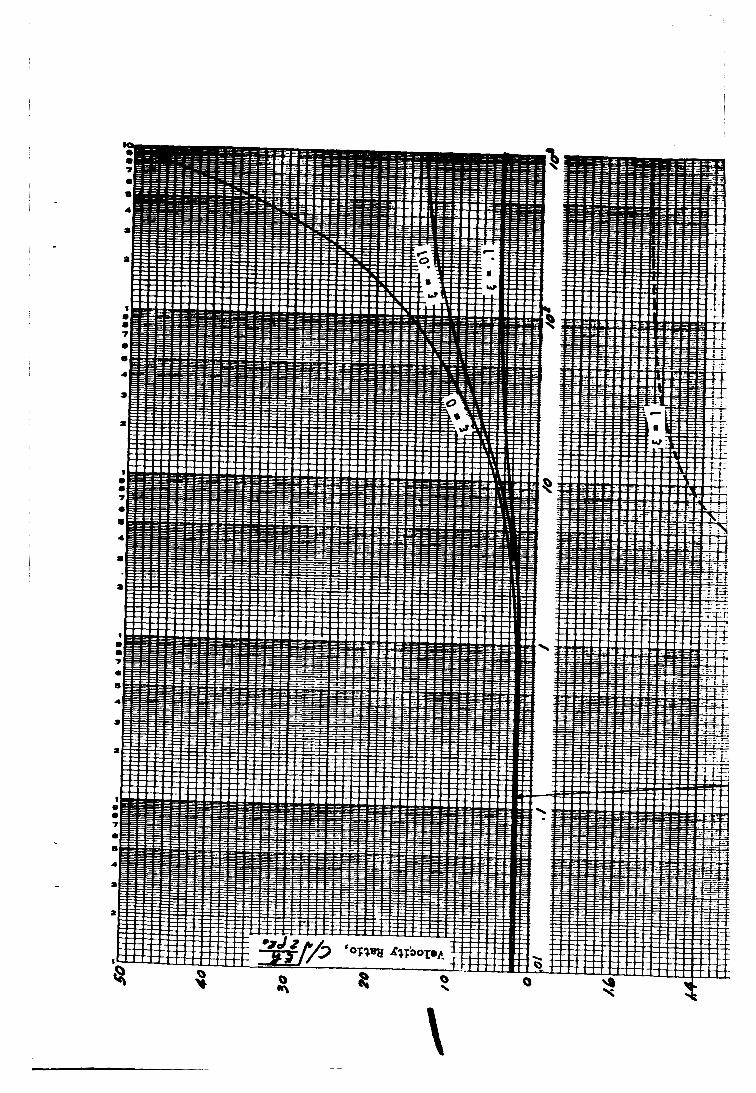
Longitudinal Velocity Ratio-Fluid Velocity to W a l l
Longitudinal Velocity Ratio-Fluid Velocity to W a l l
Longitudinal Velocity Ratio- Fluid Velocity to Wall
Longitudinal Velocity Ratio-Fluid Velocity to Wall
Longitudinal Velocity Ratio- Fluid Velocity to Wall
Longitudinal Velocity Ratio- Fluid Velocity to W a l l
Radial Velocity Ratio-Fluid Velocity to Wall Velocity
Radial Velocity Ratio-Fluid Velocity to Wall Velocity
Radial Velocity Ratio-Fluid Velocity to Wall Velocity
Radial Velocity Ratio-Fluid Velocity to Wall Velocity
Radial Velocity Ratio-Fluid Velocity to W a l l Velocity
Radial Velocity Ratio-Fluid Velocity to Wall Velocity
Attenuation Factor vs. Viscosity Pa rame te r . . . .
Radial Iner t ia Pa rame te r (‘i = 0) . . Longitudinal Inertia Parameter ( e = 0) .
Velocity For q = 0, z = 1 . Velocity F o r q = 0, z = 5 . Velocity For q = 0, z = 1 0 .
Velocity For q = 0, z - 15.
Velocity For e = 0, z = 1 . Velocity For e = 0, z = 5 . Velocity For = 0, z = 10.
F o r q = 0, z = 1 . F o r q = O , z = 5 .
F o r q = 0, z = 10.
F o r E = 0, z = 1 . F o r e = O , z = 5 . . . . F o r = 0, z = 10.
21
23 24 25 26 27 28 29 30
31
32
33
34
35
36
37
38
39
40
41
42
43 44
- vii - SID 66 -46-2

N O R T H A M E R I C A N A V I A T I O N , I N C . SPACE and INFORMATION S Y S T E M S DIVISION
. NOMENCLATURE
C
E
F
h
i
JO
J1
k
k l
k2
P
P
Q
r
R
t
U
U
V
Constants
Phase velocity
Young's modulus of ma te r i a l
Fo rce
Thickness of pipe wall
Besse l function of ze ro order
Besse l function of first o rde r
Complex propagation constant, k = k l t i k2
Phase factor
Attenuation factor
P r e s su re
A constant
Rate of mean volume flow
Coordinate in radial direction
Radius of pipe
Time
Longitudinal displacement of pipe wall
A constant
Fluid velocity component
- ix - SID 66-46-2

N O R T H A M E R I C A N A V I A T I O N , I N C . SPACE and INFORMATION S Y S T E M S DIVISION
V
W
w x
Y
z
CY
W
P
Po
P
x
c
T ~ J T3, T4
0 -
A function of r
Radial displacement of pipe wall
A constant
Coordinate in longitudinal direction
A dimensionless parameter , y = f- - : (z r ; o y 2
Viscosity parameter , z = Ro - (:YZ A dimensionless parameter , CY = - t p)liz
Poisson 's ra t io
Circular frequency of disturbance
Mass density of fluid
Mass density of pipe wall mater ia l
Vi s co sity
Proportionment of wave length, Z.rr X = wave length
7 7 L L
Po R o E
Radial iner t ia parameter , q =
Po
p R o Longitudinal iner t ia pa rame te r , 6 = -
Constants
Indicates the order of magnitude
- x - SID 66-46-2

lr
N O R T H A M E R I C A N A V I A T I O N , I N C . SPACE and INFORMATION S Y S T E M S D I V I S I O N
Subs c ri pt s
r
X
e
0
Radial direction
Longitudinal direction
Circumferential direction
Unstressed
- xi - SID 66-46-2

N O R T H A M E R I C A N A V I A T I O N , I N C . SPACE and INFORMATION S Y S T E M S DIVISION
INTRODUCTION
The problems of wave propagation of fluid i n a pipe have at t racted the attention of many investigators. hydro-power plant, blood circulation i n a human body, pressure t ransmis - sion in a pneumatic system-all depend on the dynamics of wave propagation of fluid in the conduit. propagation of propellant feed systems becomes more interesting than ever .
Water flowing through the penstock of a
)'
Since the introduction of liquid rockets , the wave
The purpose of this study is to investigate the theoretical aspect of the problem of longitudinal wave propagation in an elast ic pipe filled with an incompressible and viscous fluid. influence of iner t ia of pipe wall on wave propagation and its correlation with fluid viscosity. The investigation is divided into two par ts . The first part , wl5TcX-is documented i n this volume, is devoted to the analysis of p re s su re waves being propagated through a system a t rest. The second part; which e-xtends-the investigation to a more general situation when the p re s su re waves t r ave l through a system filled with s t reaming fluid, is published in a separate volume a s P a r t 111 of the report .
Special attention is directed toward the
The reflection of pressure waves in blood circulation has been studied by Kar reman (Reference l ) , following Witzig's approach. His resu l t s indi- cated that the influence of the viscosity on the velocity propagation is very slight and were considered by Morgan and Kiely (Reference 2 ) to be incor- rec t . Uchida (Reference 3 ) investigated the viscous flow i n a c i rcu lar pipe by superposing a pulsating flow on the steady motion. He l inearized the fundamental equations of motion by introducing the assumption of axially paral le l flow. the pipe was ignored i n the analysis.
In addition to the res t ra in t of paral le l flow, the elasticity of
An attempt to take account of the steady s t r eam in the investigation of wave propagation of viscous fluid has a l so been made by Jacobs (Reference 4). In h i s work, the average s t r eam velocity was used instead of the actual non- uniform velocity profile and the tube wall was assumed to move in the radial direct ion only. sat isfy the condition of no s l ip at the wall no mat te r how small the viscosity. The longitudinal iner t ia force , as it will be seen la te r in the discussion, has g r e a t e r influence on the wave propagation than the radial iner t ia force.
However, the fluid velocity cannot be uniform a s it has to
The present investigation follows the classical approach in formulating the problem with specific importance being accredited to the work of G. W. Morgan and J . P. Kiely (Reference 2) . The-classical Navier-Stokes
- 1 - SID 66-46-2

N O R T H A M E R I C A N A V I A T I O N , I N C . SPACE and INFORMATION S Y S T E M S DIVISION
equations of two dimensional flow with axial symmetr ic motion a r e f i r s t introduced. The elast ic equilibrium equations of the pipe a r e established on the bas i s of a thin shell. amplitude oscillation and large wave length. Fur ther simplification i s made by omitting t e r m s of small o rde r of magnitude. The t e r m s contributed by the pipe wall inertia forces , which were neglected by Morgan and Kiely, a r e retained in the analysis. F r o m the fluid and elast ic equations with appro- pr ia te boundary conditions, a character is t ic equation is obtained. After a lengthy mathematical manipulation, the character is t ic equation is reduced to a quadratic form of the complex propagation constants. This charac te r - i s t ic equation is being solved with the aid of a digital computer f rom which two se ts of phase velocities and attenuation fac tors a r e obtained for various viscosit-y and inertia parameters . This phenomenon, the existence of two phase velocities, w a s not recognized by previous investigators. The phase velocities and attenuation fac tors a r e obtained in t e r m s of three dimension- l e s s parameters , longitudinal and radial iner t ia parameters which represent the effect of pipe wall iner t ia , and viscosity parameter which exhibits the influence of viscosity. These relations a r e delineated in the form of graphs.
These equations a r e lig-earized by assuming small
- 2 - SID 66-46-2
-

N O R T H A M E R I C A N A V I A T I O N , INC. SPACE and INFORMATION S Y S T E M S DIVISION ,
ASSUMPTIONS
In formulating the mathematical model, the following assumptions a r e made.
(1) Materials of pipe follow Hooke's Law.
(2 ) Thickness of pipe, h, is smal l in comparison with radius R, thus h /R<<l .
( 3 ) Slope of pipe wall disturbances, - dR, is small; therefore , shear
and bending s t r e s ses in pipe a r e neglected.
Forced disturbances a r e harmonic in t ime.
dx
(4)
(5) Damping is small .
(6) Wave length is large compared with radius , m o r e specifically
(.)" (+)<<l UPRo
( 7 ) The disturbance of pipe is small . pipe wall may be linearized.
The boundary conditions a t the
(8) The fluid is incompressible.
- 3 - SID 66-46-2

~ ~~~ ~ ~
N O R T H A M E R I C A N A V I A T I O N , INC. SPACE and INFORMATION S Y S T E M S DIVISION
BASIC EQUATIONS
EQUATIONS OF MOTION OF FLUID
In the problem considered here , a l l motions a r e assumed to be axially symmetr ic ; therefore , the circumferential velocity component and its derivatives a r e ignored. the distance along the pipe axis and r the coordinate in the radial d i rec- tion. t e r m s a r e negligible, the Navier -Stokes' equations a r e simplified in the following form:
Cylindrical coordinates a r e adopted with x being
By restr ic t ing the problem to small disturbances so that the nonlinear
t -- ar2 r a r
where v r and vx a r e the velocity components in the radial and axial direc- t ions, p is the pressure , p is the mass density, p. is the viscosity and t is the t ime.
The equation of conservation of m a s s is
a vr vr a vx ar r ax - t - + - = o
EQUATIONS O F EQUILIBRIUM OF ELASTIC PIPE
When the thickness h of an elastic pipe is smal l compared with the radius , then the hoop tension and the tensile force in the axial direction are respectively given by
T x = - ( & t Eh u g ) 1 - ,2 ax
- 5 - SID 66-46-2

N O R T H A M E R I C A N A V I A T I O N , I N C . SPACE and INFORMATION S Y S T E M S DIVISION
where w and u a r e components of displacement of the pipe wall in radial and axial directions, E i s Young's modulus, u is Poisson 's ratio, h is the thick- ness of pipe wall and Ro is the unstressed radius of the pipe.
The normal force of fluid acting on a n elementary a r e a normal to the radius i s
and the shear force of fluid acting on an elementary a r e a normal to the radius i s
F r o m assumption ( 3 ) , it is stipulated that shear and bending s t r e s s e s in the pipe a re neglected. writ ten as
The equations of equilibrium of the pipe may be
a w 2 T0
a t 2 RO Po h - = Fr (R , X, t ) - -
where po = mass density of the pipe wall mater ia l .
Substituting the s t r e s s e s and fluid fo rces a s given in Eq. ( A ) , ( 5 ) , (61, and ( 7 ) and linearizing the boundary conditions by evaluating the forces at R o instead of a t variable radius R, the equations of equilibrium become
a u 2 a vx a v r
r = R o
6 - SID 66-46-2

N O R T H A M E R I C A N A V I A T I O N , I N C . SPACE and INFORMATION SYSTEMS DIVISION
SOLUTION O F EQUATIONS
l - A s we limit ourselves to the investigation of p re s su re waves which a r e harmonic in t ime, we may assume V i , v,, w, u and p all vary a s e i k - w t ) where
o = circular frequency of the forced disturbance
k = k l t ik2 = complex propagation constant
k l = a phase factor which represents a phase shift
k2 = an attenuation factor , which represents a measure of decay of the disturbance a s the wave t ravels along the pipe.
Therefore we se t
vr = Vr ( r ) e i(kx-ut)
vx = Vx ( r ) e i(kx-at)
i ( k x - w t ) u = U e
where Vr and V, a r e functions of r , and W and U a r e constants. By intro- ducing the expressions in Equation (12) into the continuity Equation ( 3 ) , we have the order of magnitude of Vr/Vx
1 A
2 indicates the order of magnitude.
2rrA is the wave length.
waves as stipulated in assurnption(h), 2 VX
der ivat ives a r e expected to be very small , neglecting those t e r m s in Equation (1) implies that the pressure is constant ac ross the cross-sect ion
F o r smal l damping, k = kl =-where - If we res t r ic t ourselves to the problem of long
R Rk g-, <<1. V
Since vr and its
- 7 - SID 66-46-2

N O R T H A M E R I C A N A V I A T I O N , I N C . SPACE and INFORMATION S Y S T E M S DIVISION
of the conduit and becomes a function of x and t only. Thus, we may wri te
(13) i(kx- w t ) p = P e
where P is a constant.
Substituting the expressions in (12) and (13) into Equation ( 2 )
- i w p V x + - - - dr2 r d r
Compare the relative magnitude of the coefficients of taining Vx in the above equation
the two t e r m s con-
2 2 k2 Ro
This is a very small value, in accordance with assumption (6). The t e r m k 2 V, may be neglected. Equation (14) becomes
i k P v, =- d2 v x 1 d v x i w p t--t- d r d r P P
This is a Bessel equation. I ts solution i s found to be
(16) k
U P
, Jo i s the Bessel function of ze ro o rde r and A i s an
Vx ( r ) = A Jo (a r ) t - p
i u p 112 where a = (?) a rb i t r a ry constant; and
- d r
= - a A J 1 (ar) vx
J1 i s the Bessel function of f irst order . Equation ( 3 ) , we have
By substituting Equation (12) into
- 8 - SID 66-46-2

N O R T H A M E R I C A N A V I A T I O N , I N C . SPACE and INFORMATION S Y S T E M S DIVISION
Because of the condition of symmetry, the radial velocity vanishes at the axis of the pipe. equation:
Therefore , Vr (r) may be obtained by integrating the above
i k A i k Z r p ik Vr (r) = - - 5 V, ( r ) dr = - - J 1 (ctr) --
2 U P CY
Substituting the forms of (12) and ( 1 3 ) into elast ic pipe Equations (10) and (11)
1 - - Eh [ - t - i k U w c r 1 - 0-2 Rg Ro
- p o h u 2 W = P - r=Ro
Eh [- k 2 U t - "kW] (21) 1 2 RO t i k V ,
r=Ro [ 'd? 2 - p o h ~ U = - p -
Introducing the values in Equations (17), (18) and (19), and evaluating at the boundary r = Ro, Equations (20) and (21) become
Eh i c r k U - p o h u 2 t - - 1 - ~ r 2 2 Ro Ro
Eh i c r k W - PO h u2 t '5 k2] U - - - Eh
1 - ,2 Ro
- 9 - SID 66-46-2

N O R T H A M E R I C A N A V I A T I O N , I N C . SPACE and INFORMATION S Y S T E M S DIVISION
Now, comparing the o rde r of magnitude of the t e r m s containing P in Equation ( 2 2 ) ,
A l s o , comparing the t e r m s containing A in Equation ( 2 3 )
F r o m assumption (6 ) , - ' (:r - is a very smal l number; therefore , we * P Ro
may neglect the las t t e r m in Equation ( 2 2 ) and the t e r m p- kL A J1 (ORo) in
Equation ( 2 3 ) . Rearranging, Equations ( 2 2 ) and (23) become ff
2 Eh 1 1 - 0 -
--Ut - p o h w t - - ] W - P 2 2
RO
Eh i r k 1 - u 2 Ro
J1 (QR,) ] A = O
Ro
P 2 Eh i u k k3 Ro 1 - 0 - E h 2 k 2 1 1 - u z Ro 2 o p w t p - -- - p h ~ t
Let us now examine the coefficients of W in Equation (24 ) .
u2 2 2 2 -k Ro
0 k2 Po h w
Eh 1 - E -- (1 - 2 2
RO PO 1 - u
- 10 - SID 66-46-2

, N O R T H A M E R I C A N A V I A T I O N , I N C . SPACE and INFORMATION SYSTEMS DIVISION
w w F o r small damping, - = - and represents the velocity of a wave which is of
k k l 112
the o rde r ( Eh ) i f the viscosity is neglected. Thus the above ratio 2 P R O
becomes
Examine also the coefficients of U in Equation (25).
2 The t e r m s po h w2 W and po h w U in Equations (24) and (25) a r e the inertia forces of the pipe wall.
with light fluid such a s liquid hydrogen, the ratio - = - 500 > 100. The pipe
wall iner t ia t e r m s a r e no longer small forces and will be retained in the analysis .
Fo r propellant l ines made of metall ic tubes filled
P 4.4
BOUNDARY CONDITIONS
Assuming no s l ip of the fluid at the pipe wall, we have
and
- 1 1 - SID 66-46-2

N O R T H A M E R I C A N A V I A T I O N , I N C . SPACE and INFORMATION S Y S T E M S D I V I S I O N
r
Substituting values of Equations (16) and (18), we get
i w U t -P-t k Jo (OR,) A = 0 (26 ) UP
i k 2 Ro i k J1 (aRo) - i w W t P t A = O
2 UP CY
Equations (24), (25), (26) and (27) form a se t of homogeneous equations of U , W, P and A. The character is t ic equation is obtained by setting the de te r - minant of the coefficients of the above equations equal to zero. Thus
U w P A
After a lengthy and laborious determinant manipulation, and observing that
(Fr (5- < < 1 , Equation (28) reduces to the following form W P Ro
] = o J1 (QR,) “RO
c Jo (cYR,) t
- 12 - SID 66-46-2 *

N O R T H A M E R I C A N A V I A T I O N , I N C . SPACE and INFORMATION S Y S T E M S DIVISION
where
7 and 6 a r e two dimensionless parameters derived f rom the radial and longitudinal inertia force t e r m s of the pipe wall and a r e named radial and longitudinal iner t ia parameters respectively. equation f rom which two se ts of complex solutions can be found, and then
Equation (29) is a quadratic
w can be computed. The phase velocity, c =- and the damping
k kl + ik2 -= k l ’ 0 0
fac tor , k2, may be determined by the rea l and imaginary par ts of the solu- tion of y. given by Morgan and Kiely.
When q and 6 both a r e zero, Equation (29) reduces to the form
VELOCITY DISTRIBUTION
The longitudinal velocity a t any c ros s section of the pipe i s given by Equation (16) as
k UP
V, ( r ) = A Jo (ar) + - P
If we define Q a s the ra te of mean volume flow in the pipe, then
RO RO k R: 2 ~ r r V, d r = 2 ~ r A- J 1 (aRO) t .rrP -
CY *P Q =
0
Denote the mean average velocity over a c ros s section by Vx,
- 13 - SID 66-46-2

N O R T H A M E R I C A N A V I A T I , O N , I N C . SPACE and INFORMATION S Y S T E M S DIVISION
Eliminating U and W f rom Equations (24), (26) and (27), we find the relations between A and P a s follows
A k k
where k depends on q, 6 , u and aRo; therefore , B i s a function of q, 6 , u and aR0.
Using the relation (32) , we get the rat io of the longitudinal velocity and the mean average velocity to be
and 2
2 (1 - ) T l t (1 - u 2 ) T l - (1 - 2 u ) k 2 R- 2 3
However, in some respects it is more interesting and meaningful to express the velocity profile i n t e r m s of ra t io of the fluid velocity and pipe wall velocity. F rom Equations (12) and (26), the longitudinal pipe wall velocity is
V, (R,) = - i w U = A Jo (OR,) t - k P UP
Using again the relation (32), the longitudinal velocity ra t io between fluid and pipe wall becomes
B 1 t - Jo (ar) v, ( r ) 2
B 2
1 t - Jo (aRo) v, (Ro) -
- 14 -
(34)
SID 66-46-2

~
I
N O R T H A M E R I C A N A V I A T I O N , INC. SPACE and INFORMATION S Y S T E M S DIVISION
Similarly, the radial velocity ra t io between fluid and pipe wall i s
- 15 - SID 66-46-2

N O R T H A M E R I C A N A V I A T I O N . I N C . SPACE and INFORMATION S Y S T E M S DIVISION
DISCUSSION OF RESULTS
112 1 / 2 Introducing the notation z = Ro (y) , thus aRo = Ro (9) = f i z ,
it is recognized that the solution of Equation (29) is character ized by the dimensionless quantity, z , which for the convenience of discussion is named viscosity parameter . functions with complex arguments. A general solution of the closed form is difficult to achieve. IBM 7094 digital computer. Fo r simplicity, Poisson’s ra t io u i s assumed to be 0. 3 throughout the calculations. of the quadratic form. F o r each set of parameter values q, E, and z, we get two se ts of complex solutions, namely
The character is t ic equation is composed of Bessel
Therefore , a numerical method is used with the
Equation (29) is an equation
Y 2 = * k l 0 i k 2 (2zo)”2 T3 -k i T4
which lead to two se t s of phase velocity, c, and damping factor k2.
Equation ( 3 6 ) gives
and Equation (37) gives
( 3 7 )
- 17 - SID 66-46-2

N O R T H A M E R I C A N A V I A T I O N , I N C . SPACE and INFORMATION S Y S T E M S DIVISION
The relations between phase velocities and viscosity parameters a re shown in Figures 1 and 2. relationship when the radial iner t ia parameter is very small o r q = 0, and Figure 2 gives the relationship when the longitudinal iner t ia parameter is very small o r = 0. Figures 3a through 3e, 4a, and 4b a r e the longitudinal velocity profiles. In each of these figures, there are two sets of curves corresponding to the two se ts of resul ts given by Equations (38) and (39). One se t of the resu l t s , where the pipe wall velocity i s relatively small as compared with the fluid velocity, is here named wave propagation of the f i rs t kind. longitudinal velocity, is identified as wave propagation of the second kind.
Figure 1 gives the velocity-viscosity-parameter
The other set of resu l t s , where the pipe wall has relatively large
F o r wave propagation of the first kind the motion of the pipe wall is very small (see Figures 3a through 3e, 4a and 4b); therefore , the phase velocities a r e more o r less independent f r o m the pipe iner t ia parameters but a r e greatly influenced by the viscosity parameter of the fluid, a s shown in Figures 1 and 2. When the viscosity parameter is small , corresponding to large viscosity and smal l disturbing frequency, the velocity profile, a s shown in Figures 3a through 3e, 4a and 4b, is nearly independent f rom the iner t ia parameters and follows the well-known pattern of parabolic distribu- tion. When the viscosity parameter increases , the influence of iner t ia parameters on velocity profiles increases a l so . When the viscosity param- e t e r is very large, very sha rp velocity gradients a r e developed near the pipe wall and the velocity profiles exhibit the boundary layer flow.
F o r wave propagation of the second kind, the phase velocity of the fluid 7
is nearly equal t o E , the elast ic wave velocity of the pipe wall, and is
nearly independent from the viscosity pa rame te r s as shown i n Figure 1. The pipe wall has large motion in the longitudinal direction for the wave propaga- tion of the second kind, hence the velocity profiles a r e greatly influenced by the longitudinal iner t ia . When the longitudinal iner t ia parameter is smal l ( s ee Figures 3a and 3b), the velocity profiles follow the s imi la r pattern of the first kind and the wall velocity is generally out of phase with the fluid velocity except for fluid of large viscosity (corresponding to smal l z-value). A s the longitudinal iner t ia parameter increases , the wall velocity surges forward and finally the velocity distributions r eve r se the pattern of those of the f i r s t kind, a s depicted in Figures 3d and 3e.
- 18 - SID 6 6 - 4 6 - 2
~~

N O R T H A M E R I C A N A V I A T I O N , I N C . SPACE and INFORMATION S Y S T E M S DIVISION
CONCLUSIONS
F r o m the resu l t s , it may be concluded that the longitudinal iner t ia parameters have much grea te r influence on the wave propagations than the radial iner t ia parameters . The radial iner t ia pa rame te r s , which may be expressed as
2 2 2 Po w Ro - --=(2) u2R$ <<1
E - E q =
PO
(where 2rXP is the wave length of the wave traveling in the elast ic mater ia l of the pipe) a r e very smal l values. The phase velocities and velocity pro- fi les shown in Figures 2 , 4a, and 4b a r e practically identical with those shown in F igures 1 and 3a for = 0. Thus, the effects of radial iner t ia parameters on wave propagation a r e negligible. In the case where the wave length of the elast ic mater ia l of the pipe i s very small and approaching the o rde r of the radius of the pipe, the influence of radial inertia parameters on wave propagation may become prominent.
The radial velocity patterns of the fluid for various parameters a r e shown in Figures 7a through 7c and 8a through 8c in the form of ra t io to wall radial velocity.
The decay of the disturbing waves depends on the Poisson's ra t io and A s we fixed the Poisson's ra t io in our investigation, the
When the viscosity
the viscosity. damping factor var ies with the viscosity parameter only, and it is a lmost independent f rom the pipe wall inertia parameters . parameter is small , which corresponds to la rge viscosity and smal l d i s - turbing frequency, the wave propagation of the first kind possesses large values of attenuation factor while the waves of the second kind have very sma l l damping effects. When the viscosity parameter i s small , waves of the second kind move as a rigid body ( r e fe r to Figures 3a through 3e with z = 1) ; the viscosity of the fluid plays a very sma l l role in creating the shear fo rces which a r e the source of damping. When the viscosity parameter is l a rge , the attenuation factors become very small in both cases . Figure 9 gives the plots of attenuation factor vs . viscosity parameter of wave propa- gation of both kinds. of pipe wall iner t ia parameters .
These curves a r e practically the same for a l l values
The work reported here deals with wave propagation in an elast ic pipe fi l led with incompressible viscous fluid at res t . investigation t o a more general situation where the p re s su re waves t rave l through a sys t em filled with streaming fluid is discussed in Part 111 of this repor t .
The extension of this
- 19 - SID 66-46-2
\

UORTH AMERICAN AVIATION, INC. SPACE urbd INZ.URh1ATION S Y S T E M S DIVISION
A k
c k 0 w k
0 d
SID 66-46-2 - 2 1 , 2 2 --

N O R T H A M E R I C A N A V I A T I O N , I N C . SPACE and INFORMATION SYSTEMS DIVISION
7 0 9 e 7
6
5
4
3
2
1 9 e 7
6
5
4
3
2
1 9 e 7 6
5
4
3
2
1
9 e 7
6
5
4
3
2
1 9 R 1
ti
4
. . . . . ~ . _ _ _ ~ - . . . . . . . . . ... i i +
* - _ .
. 7 - . - - - . . . . . . .
. . . , _ . .
t . .
- 9
1 ' 1 1
-+-F
- 23 - SID 66-46-2

N O R T H A M E R I C A N A V I A T I , O N , I N C . SPACE and INFORMATION S Y S T E M S D I V I S I O N
Figure 3a. Longitudinal Velocity Prof i le for r\ = 0, = 0
- 24 - SID 66-46-2

N O R T H A M E R I C A N A V I A T I O N , INC. SPACE and INFORMATION S Y S T E M S DIVISION
Figure 3b. Longitudinal Velocity Prof i le for 11 = 0, 5 = 1
- 25 - SID 66-46-2

N O R T H A M E R I C A N A V I A T I O N , I N C . SPACE and INFORMATION S Y S T E M S DIVISION
Veloc
- 26
ity
-
Profi le for 11 = 0, c = 4

I -
Figure 3d. Longitudinal Velocity Prof i le for 7 = O, s = 6
- 27 - SID 66-46-2

N O R T H A M E R I C A N A V I A T I O N , I N C . SPACE and INFORMATION S Y S T E M S D I V I S I O N
h c,
0 0
0) w
- c
4 c U
c,
o, c 0
- a .I-
1 .O
2.0
2.6
2 .* 2.2
2.0
1 .o
1.6
. .
Figure 3e. Longitudinal Velocity Profile f u r 'I= 0 , 6 = 10
- 28 -

N O R T H A M E R I C A N A V I A T I O N , I N C . SPACE and INFORMATION S Y S T E M S D I V I S I O N
h c, .C
4 E
U U
._ a
-v- cs, c 0 J
- 4
- 5
- I W ! ! ! ! ! ! ! ! ! ! ! ! ! ! ! ! ! ! ! ! ! ! ! ! ! ! ! ! ! " " " " " ~
- a
- 9
-ID -1 0
Figure 43. Longitudinal Vel0 city Profile for q = 10-6
SID 66-46-2

N O R T H A M E R I C A N A V I A T I O N , I N C . SPACE and INFORMATION S Y S T E M S D I V I S I O N
x +l .C
U 0
0) > -
L-In! ! ! ! ! ! ! ! ! ! ! ! ! ! ! ! ! ! ! ! ! ! ! " " ' I ! ! ! ! ! ! ! ! U
I . ' ! ! ! ! ! ! ! ! ! ! ! ! ! ! ! ! ! ! I ! ! ! ! ! ! ! ! ! ! ! ! ! ! ! : ! ! ! : I
Y ! ! ! ! ! ! ! ! ! ! ! ! ! ! ! ! ! ! ! ! ! ! ! ' ! ! ! ! ! ! : ! ! ! ! ! ! ! ! l
-10 -1 .o -0.8 -0.8 -0.4 -0.2 0 0.2 0.4 0.6 0.6 t .o
Figure 4b. Longitudinal Velocity Prof i le f o r = 0 , 'I= 10- 1
- 30 -

N O R T H A M E R I C A N A V I A T I O N , I N C . SPACE and INFORMATION S Y S T E M S DIVISION
4998-36 001 000
F i g u r e 5a. Longitudinal Velocity Ratio-Fluid Velocity to Wall Velocity fo r 11 = 0, 2 = 1
- 31 - SID 66-46-2

N O R T H A M E R I C A N A V I A T I O N , I N C . SPACE and INFORMATION S Y S T E M S DIVISION
Figure 5b. Longitudinal Velocity Ratio-Fluid ' 1 = 0 , 2 = 5
- 3 2 -
Figure 5b. Longitudinal Velocity Ratio-Fluid ' 1 = 0 , 2 = 5
Velocity to W a l l V,\locity for
- 3 2 -

N O R T H A M E R I C A N A V I A T I O N , I N C . SPACE and INFORMATION S Y S T E M S DIVISION
4998-36 003 000
10
5
0
3 s - 5 - 0 w - - e 3 10
0 +r
3 .r 8 -15
Q) w '0
3 c -m LL
I
0
*, *I -#!5 oz
c
-r
..-
3 8 c - -10 Q) w
-15
-40 -1 .o -0.0 -0.0 -0.4 -0.L 0.1 0.4 0.b 0.. 1 .o
F i g u r e 5c. Longitudinal Velocity Ratio-Fluid Velocity to Wall Velocity for q = 0, z = 10
- 33 - SID 66-46-2

N O R T H A M E R I C A N A V I A T I O N , I N C . SPACE and INFORMATION S Y S T E M S DIVISION
Figure 5d. Longitudinal Velocity Ratio- Fluid q = 0, Z = 15
- 3 4 -
Figure 5d. Longitudinal Velocity Ratio- Fluid q = 0, Z = 15
- 3 4 -
Velocity to w Jll
SID 66-46-2
Velocity for

/-
N O R T H A M E R I C A N A V I A T I O N , INC. SPACE and INFORMATION S Y S T E M S DIVISION ~
I
1 ' .
3
c a 3 0 c,
3 c 0 0
e > - 0
3 LL
I
c
c
0
4.l c
a a
3
Figure 6a. Longitudinal V-elocity Ratio-Fluid Velocity to W a l l Velocity for k = O , 2 = 1
- 35 - SID 66-46-2

N O R T H A M E R I C A N A V I A T I O N , I N C . SPACE and INFORMATION S Y S T E M S DIVISION
t
4 9 9 0 - 1 6 005 000
Figure 6b. Longitudinal Velocity Ratio-Fluid Velocity to W a l l Velocity for E = o , 2 = 5
- 36 - SID 66-46-2
~ ~~

N O R T H A M E R I C A N A V I A T I O N , INC. S P A C E 6lld INFORMATION S Y S T E M S DIVISION
Figure 6c. Longitudindl Velocity Ratio- Fluid Velocity to Wall Velocity f o r E = 0, z = 10
- 37 - SID 66-46-2

N O R T H A M E R I C A N A V I A T I O N , I N C . SPACE and INFORMATION S Y S T E M S DIVISION
1 .f!
. . . mv:.. . - .. . --. . -- . -~ . _ . . ~ , . . . . . . . . . . . . . . . . . .
h c,
V 0
u >
.r
c
r c m z 0 c,
c s c Q >
0
c, p:
.e-
m
3 c V 0
Q > c
1 .1
1 .o
0 . S
0 . 8
0 . 7
0 .e
0 . 5
0 . 4
0 . 3
0.2
0 .1
e - 1 0
Figure 7a. Radial Velocity Ratio-Fluid Vel0 '1= 0, z = 1
- 38 -
'c i ty to W a l l V 'eloc ity for
SID 66-46-2

N O R T H A M E R I C A N A V I A T I O N , I N C . SPACE end INFORMATION S Y S T E M S DIVISION
1 .1
1 . o
0 . 9
3 g 0 . 0
.r
c 0) z - 7
0 . 1 3 0 4.8
3 0 . 6 .r
0" > 0.Y
a
, 0 . 4
c Q
u .r - LL
0
c, * t-
0 . 3
3 .r W 0
> c 0 . 2
0 . 1
a
- 0 . 1 - 1
. . .
. . .
. . .
. . .
. . .
. . . __c . . . . . .
. . . . . .
. . .
. . .
. . .
. . .
. . .
. . . . . .
. . ---.
. . . . .
. . . . .
.
1 9 9 8 - 4 8 DOL 300
Figure 7b. Radii1 V,>locity Ratio-Fluid Velocity to W a l l Velocity for q = o , 2 = 5
- 39 - SID 66-46-2

N O R T H A M E R I C A N A V I A T I O N , I N C . SPACE and INFORMATION S Y S T E M S DIVISION
3 c u 0
al w - c F Q 3 0 +I
3 c u 0
al > -0
1
LL
I
0
c, Q
c - .r
a
3 c v 0
al w c
1 . l
1 .a
0 . s
0 .4
0 . 1
0 . 6
0.1
0.4
U . 3
0.2
0 . 1
0
- 0 . 1
- 0 . z - I
I 1 ' - , ,
.. _I. . -1 . .- . - 0 . 1 -0.8
F i g u r e 7c. Radial Velocity Ratio-Fluid Velocity to W a l l Velocity for '1 = 0, z = 10
- 40 -

I 1 .
N O R T H A M E R I C A N A V I A T I O N , I N C . SPACE and INFORMATION S Y S T E M S DIVISION
b 9 9 8 - 4 6 004 000
3 .r V 0
W w - - c Q 3 0 c,
3 .- u 0
W > c
0
c,
CL
.c
a
3 iJ 0
W w -
1 .L
1.1
1 .o
0.9
0.8
0 . 7
0 .8
0 . 5
0.4
0 . 3
0 .t
0.1
8 - 1 e
F i g u r e 8a. Radial Velocity Ratio-Fluid Velocity to Wall Velocity for =.o, z = 1
- 41 - SID 66-46-2

N O R T H A M E R I C A N AVlATI .ON, I N C . SPACE and INFORMATION S Y S T E M S DIVISION
4 9 9 8 - 4 1 0 0 1 0 0 0
1.1
1 .o
0 . 1
0.8
0 . 7
a.6
0 . 5
0.4
0 . 3
0.2
0.1
a
-0 .1
_ - I I l l I I I I I I I I 1 I 1 I , :. I I I I 1 I I 1 I 1 I I ! I 1 L I I J
- 1 .o -0.8 4 .1 -0 .1 - 0 . t 0 0 . t 0 . 4 0 . 1 0 . 1 8 .a
Figure 8b. Radiql Velocity Ratio-Fluid Velocity to Wall Velocity for c = o , z = 5
- 42 -

N O R T H A M E R I C A N A V I A T I O N , I N C . SPACE and INFORMATION S Y S T E M S DIVISION
1 .
4 0 9 1 - 4 s O D 1 D O G
1 . I
u
Figure 8c. Radial Velocity Ratio-Fluid Velocity to W a l l Velocity f o r g = 0, z = 10
- 43 - SID 66-46-2

N O R T H A M E R I C A N A V I A T I O N , I N C . SPACE and INFORMATION S Y S T E M S D I V I S I O N
1c E E 7 E
4
2
1 S E 7
6
5
4
3
2
I S
7
6
5
4
e
3
2
1 9 e 7
6
5
4
3
2
I S e 7
6
5
4
3
2
1
I
?
b \
! h
I
b
. L 0 +J
m L m n.
c cn 0 V cn > .r .
.
0 \
SID 66-46-2

I . N O R T H A M E R I C A N A V I A T I O N , INC. SPACE and INFORMATION SYSTEMS DIVISION .
I
1.
2.
3.
4.
REFERENCES
Karreman, George. "Some Contributions to the Mathematical Biology of Blood Circulation. System, Bulletin of Mathematical Biophysics, Vol. 14 (1952).
Reflections of P r e s s u r e Waves in the A r t e r i a l
Morgan, G. W . , and J . P. Kiely. "Wave Propagation in a Viscous Liquid Contained in a Flexible Tube, ' I Journal of the Acoustical Society of America, Vol. 26, No. 3 (May 1954).
Uchida, Shigeo. "The Pulsating Viscous Flow Superposed on the Steady Laminar Motion of Incompressible Fluid i n a Circular Pipe, ' I
Zeitschrift fur Angewandte Mathematik und Physik, Vol. 7 (1956).
Jacobs , Robert B. Viscous Liquid Blowing in a Distensible Tube of Appreciable Mass, I '
Bulletin of Mathematical BioDhvsics, Vol. 15 (1953).
"On the Propagation of a Disturbance Through a
- 45 - SID 66-46-2