si-sic heat exchangers with highly structured surface ... · si-sic heat exchangers with highly...
TRANSCRIPT
Si-SiC heat exchangers with highly structured surface elements for recuperative gas burners
A. Ortona*, SUPSI, Switzerland; S. Gianella, Erbicol, Switzerland; D. Trimis, V. Uhlig, R. Eder, TU Bergakademie Freiberg, Germany; E. Boulet, C. Chazelas, Institut Français du textile et de l’habillement, France; T. Grämer, NOXMAT, Germany; G. D’Amico, P. Fino, Politecnico di Torino, Italy; E. Cresci, J. G. Wünning, WS Wärmeprozesstechnik, Germany; H. Altena, Aichelin, Austria; F. Beneke, M. Debier, European Committee of Industrial Furnace and Heating Equipment Associations CECOF, Belgium

Outline
• Motivation
•CFD analysis
•Textile
•Ceramisation
•Testing
•Results
2
3
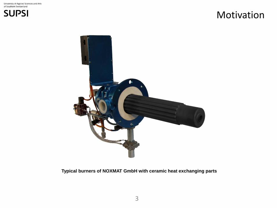
Typical burners of NOXMAT GmbH with ceramic heat exchanging parts
Motivation
Motivation
4
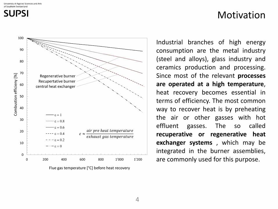
Industrial branches of high energy consumption are the metal industry (steel and alloys), glass industry and ceramics production and processing. Since most of the relevant processes are operated at a high temperature, heat recovery becomes essential in terms of efficiency. The most common way to recover heat is by preheating the air or other gasses with hot effluent gasses. The so called recuperative or regenerative heat exchanger systems , which may be integrated in the burner assemblies, are commonly used for this purpose.
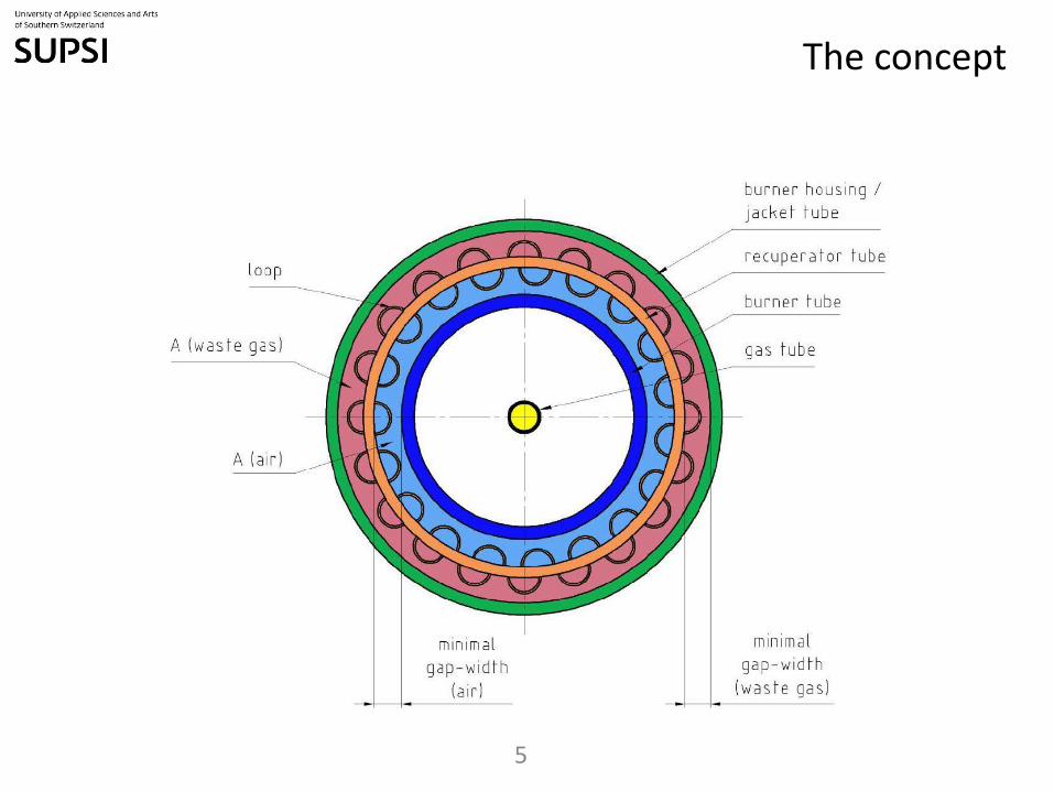
The concept
5
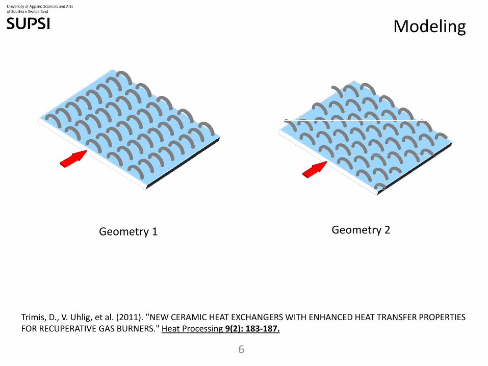
Modeling
6
Geometry 1 Geometry 2
Trimis, D., V. Uhlig, et al. (2011). "NEW CERAMIC HEAT EXCHANGERS WITH ENHANCED HEAT TRANSFER PROPERTIES FOR RECUPERATIVE GAS BURNERS." Heat Processing 9(2): 183-187.
7
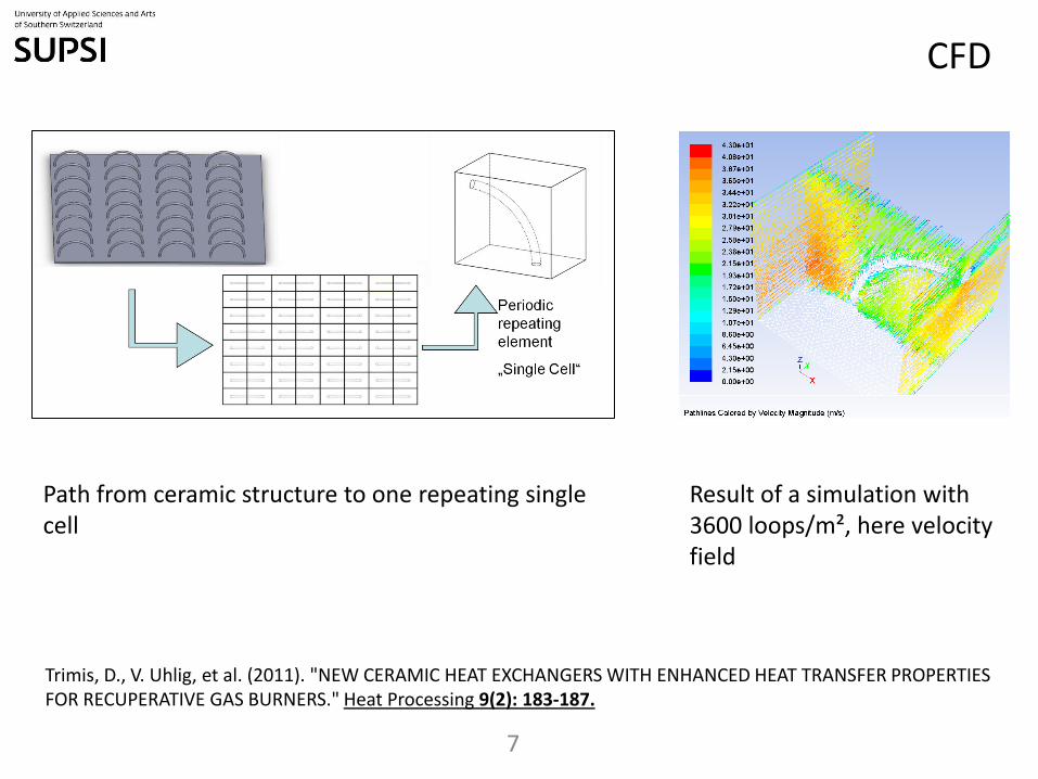
Path from ceramic structure to one repeating single cell
Result of a simulation with 3600 loops/m², here velocity field
CFD
Trimis, D., V. Uhlig, et al. (2011). "NEW CERAMIC HEAT EXCHANGERS WITH ENHANCED HEAT TRANSFER PROPERTIES FOR RECUPERATIVE GAS BURNERS." Heat Processing 9(2): 183-187.

CFD results
8
Trimis, D., V. Uhlig, et al. (2011). "NEW CERAMIC HEAT EXCHANGERS WITH ENHANCED HEAT TRANSFER PROPERTIES FOR RECUPERATIVE GAS BURNERS." Heat Processing 9(2): 183-187.
This example calculation indicates, that the targeted recuperator design will result in either significantly higher heat recovery levels at the same overall burner size as the current recuperative burners and slightly higher pressure losses, or alternatively to approximately the same heat recuperation level at significantly smaller size and lower pressure losses
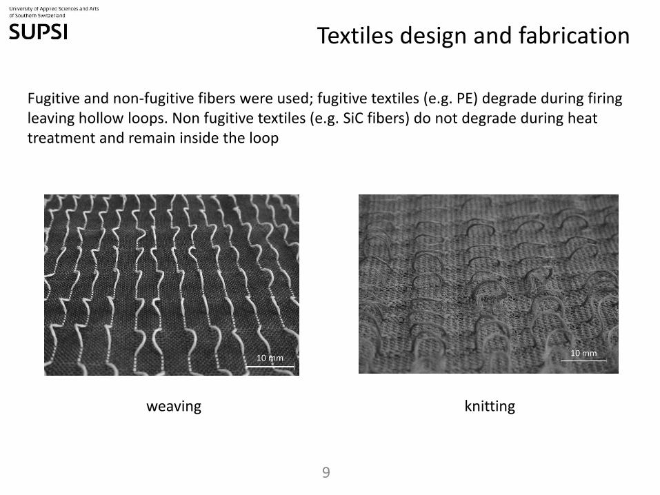
Textiles design and fabrication
9
weaving knitting
Fugitive and non-fugitive fibers were used; fugitive textiles (e.g. PE) degrade during firing leaving hollow loops. Non fugitive textiles (e.g. SiC fibers) do not degrade during heat treatment and remain inside the loop
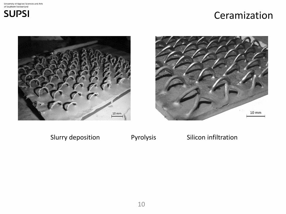
Ceramization
10
Slurry deposition Silicon infiltration Pyrolysis
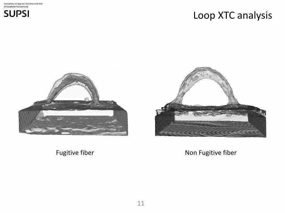
Loop XTC analysis
11
Fugitive fiber Non Fugitive fiber
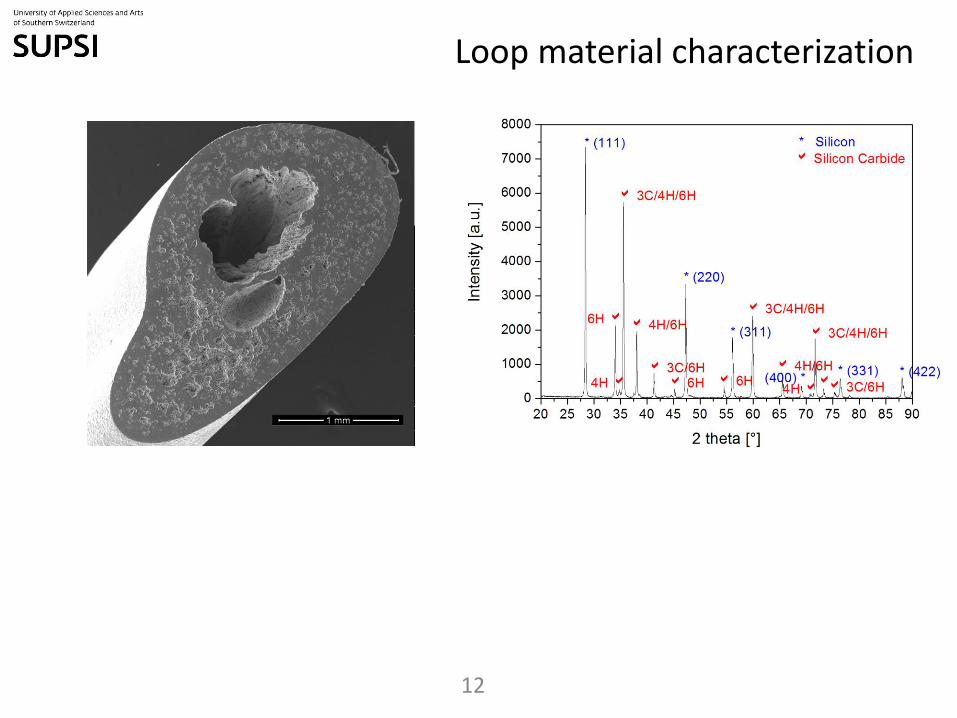
Loop material characterization
12
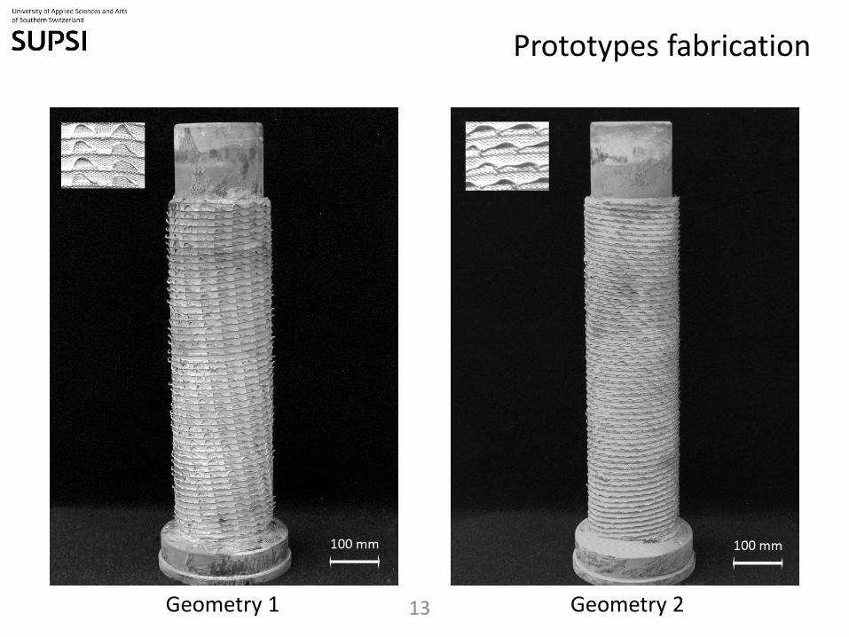
Prototypes fabrication
13 Geometry 1 Geometry 2
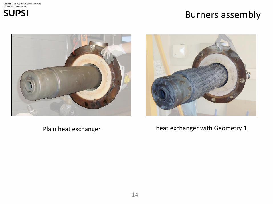
Burners assembly
14
Plain heat exchanger heat exchanger with Geometry 1
Burner testing
15
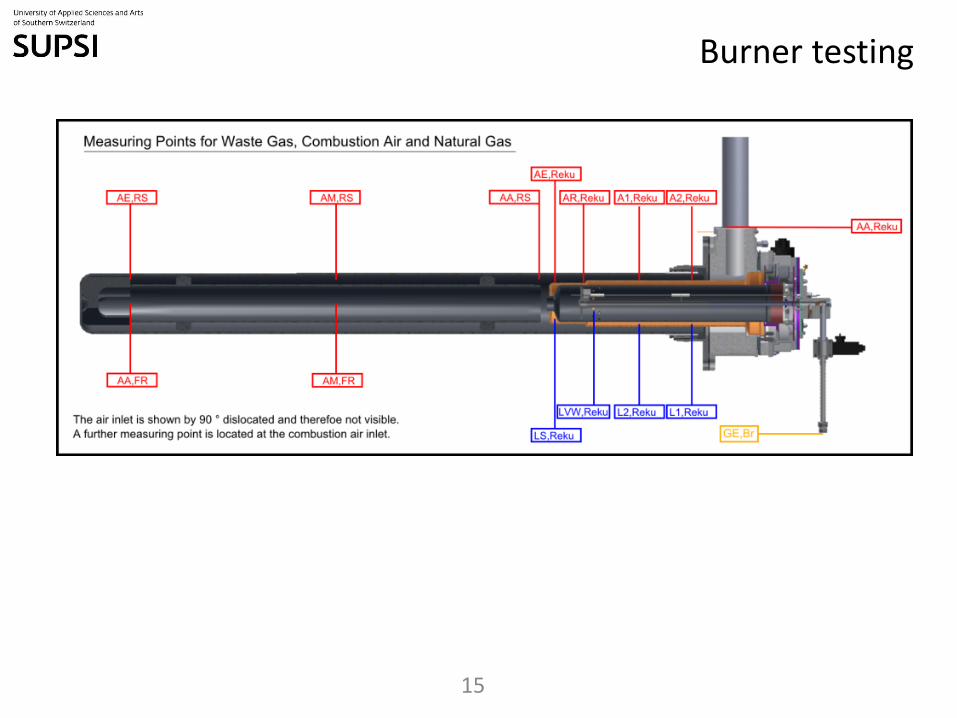
Figure 11 Ov erv iew of all measuring points (red f or waste gas, y ellow f or natural gas, blue f or combustion
air)
Via these measurements the f ollowing parameters could be determined:
· Av erage temperatures at inlets and outlets as well as in the jacket and f lame tube
· temperature prof iles throughout the recuperator
· waste gas mixture
· f iring ef f iciency
· pressure drops
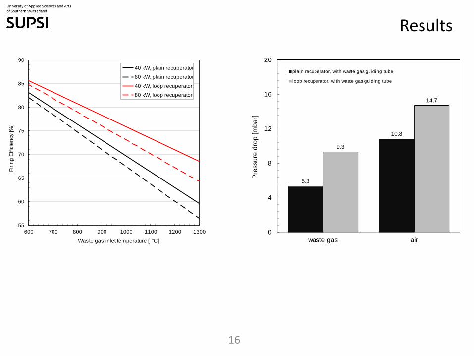
By using the loop recuperator with geometry 1 the f iring ef f iciency was increased by 7-9 % depending on
the waste gas inlet temperature. Although tests hav e been not y et perf ormed, we expect a f urther
increase in the ef f iciency by using of loop geometry 2 and an optimizing the waste gas guiding tube. The
f iring ef f iciency at capacities powers of 40 and 80 kW with at dif f erent waste gas inlet temperatures are
shown in Figure 12. The increase of the ef f iciency causes a higher pressure drop at the air and at the waste
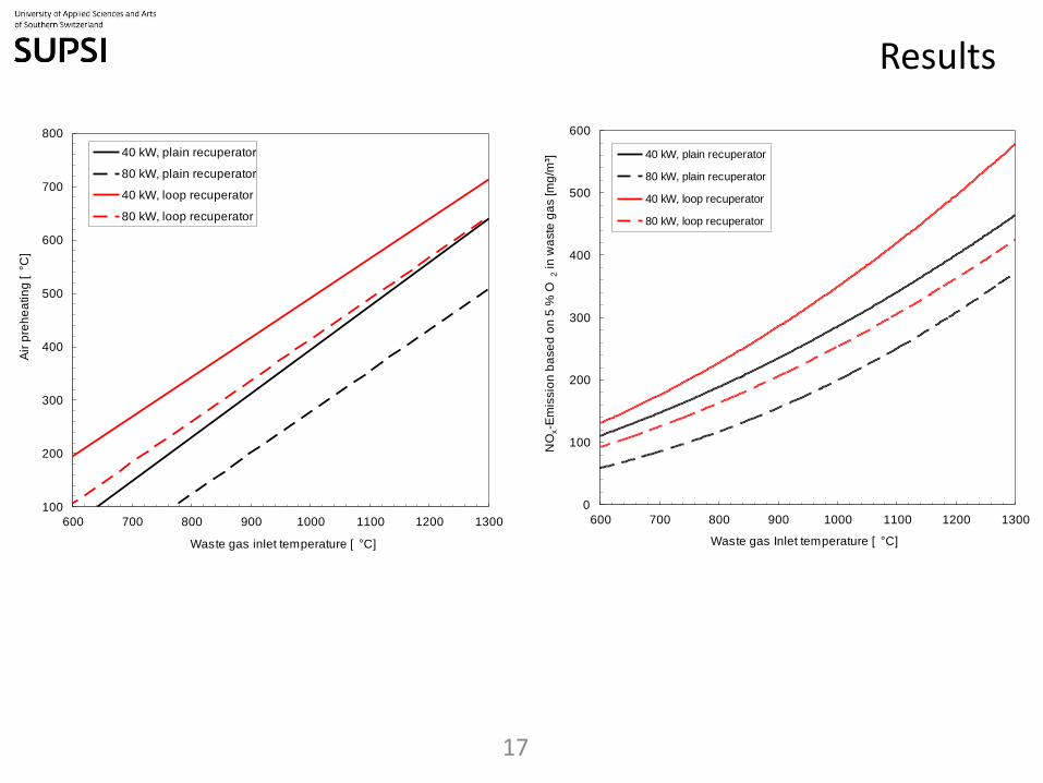
gas sides (see Figure 13). The air preheating (Figure 14) could be increased by 60-80 °C with the use of the
new recuperator geometry .
Certainly the raising of ef f iciency and air preheating causes an increase of the NOx emissions in the waste
gases. At 40 kW they raise about 25 %, at 80 kW about 13 % (Figure 15). With specif ic arrangements
concerning to the combustion sy stem a reduction of the emissions could be achiev ed.
As expected f or this kind of materials the Si-SiC loops are v ery f ragile. Af ter multiple assembling many loops
on the waste gas side were broken and lost. Theref ore a possibility f or protecting the loops during the
assembling has to be dev eloped.
Results
16
55
60
65
70
75
80
85
90
600 700 800 900 1000 1100 1200 1300
Fir
ing
Effic
ien
cy [%
]
Waste gas inlet temperature [ °C]
40 kW, plain recuperator
80 kW, plain recuperator
40 kW, loop recuperator
80 kW, loop recuperator
5.3
10.8
9.3
14.7
0
4
8
12
16
20
waste gas air
Pre
ssu
re d
rop
[m
ba
r]
plain recuperator, with waste gas guiding tube
loop recuperator, with waste gas guiding tube
Results
17
0
100
200
300
400
500
600
600 700 800 900 1000 1100 1200 1300
NO
x-E
mis
sio
n b
ase
d o
n 5
% O
2 in
wa
ste
ga
s [m
g/m
³]
Waste gas Inlet temperature [ °C]
40 kW, plain recuperator
80 kW, plain recuperator
40 kW, loop recuperator
80 kW, loop recuperator
100
200
300
400
500
600
700
800
600 700 800 900 1000 1100 1200 1300
Air
pre
he
atin
g [°C
]
Waste gas inlet temperature [ °C]
40 kW, plain recuperator
80 kW, plain recuperator
40 kW, loop recuperator
80 kW, loop recuperator
Conclusions
18
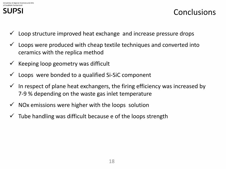
Loop structure improved heat exchange and increase pressure drops
Loops were produced with cheap textile techniques and converted into ceramics with the replica method
Keeping loop geometry was difficult
Loops were bonded to a qualified Si-SiC component
In respect of plane heat exchangers, the firing efficiency was increased by 7-9 % depending on the waste gas inlet temperature
NOx emissions were higher with the loops solution
Tube handling was difficult because e of the loops strength
Acknowledgements
19
The research leading to these results has received funding from the European Union Seventh Framework Programme (FP7/2007-2013) under grant agreement n° 227551 (Project CEREXPRo).
20
Hybrid Materials Group at ICIMSI
Dr. ing. Giulio Scocchi materials properties
Dr. Danilo Sergi process simulation
Ing. Claudio D’Angelo materials properties
Ing. Giovanni Bianchi experiments set up
Ing. Luca Ferrari thermo fluid dynamics
Ing. Ehsan Rezaei characterization
Prof. ing. Alberto Ortona* [email protected]
University of Applied Sciences (SUPSI) www.supsi.ch
The iCIMSI Research Institute, www.icimsi.ch
Address: Galleria 2, CH 6928, Manno, Switzerland
Telephone: +41 58 6666611
*Contact
Acknowledgements