sia-f - relko enerji | enerjiniz olmaya hazırız manual.pdf · the sia-f equipment has two inputs...
TRANSCRIPT

EN_SIA_MANU_SIAF_R010.Docx
USER´S MANUAL
SIA-F Overcurrent & Earth Fault Protection Relay
www.fanox.com Rev. 10 2/138
1. RECEPTION, HANDLING & INSTALLATION .................................................................................. 5
1.1. Unpacking ......................................................................................................................................... 5
1.2. Reception of relays .......................................................................................................................... 5
1.3. Handling electronic equipment ...................................................................................................... 5
1.4. Installation, commissioning and service ...................................................................................... 6
1.5. Storage .............................................................................................................................................. 6
1.6. Recycling .......................................................................................................................................... 6
2. DIMENSIONS AND CONNECTION DIAGRAMS ............................................................................. 7
2.1. Frontal view ...................................................................................................................................... 7
2.2. Case dimensions ............................................................................................................................. 8
2.3. Connection diagram ........................................................................................................................ 9
2.4. Terminals .......................................................................................................................................... 11
3. DESCRIPTION .................................................................................................................................. 12
3.1. Introduction ...................................................................................................................................... 12
3.2. Equipment description .................................................................................................................... 12
3.3. Functional Diagram ......................................................................................................................... 15
3.4. Selection & Ordering data ............................................................................................................... 16
3.5. Phase CT and neutral CT selection ............................................................................................... 17
3.5.1. External current transformers advantages .......................................................................... 17
3.5.2. Load curve for relay SIA-F/1 .................................................................................................. 18
3.5.3. Load curve of relay SIA-F/5 .................................................................................................... 18
4. PROTECTION FUNCTIONS ............................................................................................................. 19
4.1. 50P Function. Phase instantaneous phase overcurrent ............................................................. 19
4.2. 50/51P Function. Phase inverse time overcurrent ....................................................................... 19
4.3. 50N/G Function. Neutral instantaneous overcurrent ................................................................... 20
4.4. 50/51N/G Function. Neutral inverse time overcurrent ................................................................. 21
4.5. Cold Load Pickup ............................................................................................................................ 21
4.6. Trip block protection for the switchgear ....................................................................................... 23
4.7. 52 Function. Circuit breaker monitoring ....................................................................................... 23
4.7.1. Circuit breaker opening and closing commands ................................................................ 26
4.7.2. Counter to register the number of openings ....................................................................... 26
4.7.3. Counter to register the accumulated amps: I2t ................................................................... 26
4.7.4. Excessive openings per time ................................................................................................. 26
4.8. 49 Function. Thermal Image Protection ........................................................................................ 27
4.9. 50BF Function. Circuit Breaker opening fault .............................................................................. 30
4.10. 68 Function. Trip Bus ...................................................................................................................... 31
4.11. General Settings .............................................................................................................................. 32
4.12. Setting Group ................................................................................................................................... 33
4.13. Protection Settings .......................................................................................................................... 34
4.14. IEC 60255-151 Curves ..................................................................................................................... 36
4.15. ANSI-IEEE Curves ............................................................................................................................ 40
www.fanox.com Rev. 10 3/138
4.16. Application examples ...................................................................................................................... 44
5. MONITORING AND CONTROL ........................................................................................................ 49
5.1. Measurements .................................................................................................................................. 49
5.2. Counters ........................................................................................................................................... 49
5.3. States and Events ............................................................................................................................ 50
5.4. Fault Reports .................................................................................................................................... 60
5.5. Date and Time by Real Time Clock (RTC) ..................................................................................... 60
5.6. Oscillography ................................................................................................................................... 61
5.7. Digital Inputs .................................................................................................................................... 64
5.8. Configurable Outputs ...................................................................................................................... 64
5.9. Programmable Logic Control & Digital Outputs ........................................................................... 64
5.10. 86 Function. Trip Output Lockout .................................................................................................. 68
5.11. Self-diagnosis .................................................................................................................................. 69
5.12. Commands ....................................................................................................................................... 69
5.13. Test Menu ......................................................................................................................................... 70
5.14. Power supply.................................................................................................................................... 70
6. TECHNICAL SPECIFICATIONS AND STANDARDS ...................................................................... 71
6.1. Technical Specifications ................................................................................................................. 71
6.2. Thermal resistance .......................................................................................................................... 74
6.3. Standards ......................................................................................................................................... 75
6.4. Output relays .................................................................................................................................... 78
7. COMMUNICATION AND HMI ........................................................................................................... 79
7.1. Front Communication: USB ............................................................................................................ 79
7.2. Rear Communication: RS485 ......................................................................................................... 79
7.3. LED Indicators.................................................................................................................................. 80
7.4. LCD and keypad ............................................................................................................................... 81
7.5. SICom Communications program.................................................................................................. 81
7.5.1. How to install SICOM Software .............................................................................................. 82
7.6. Setting up the session: Password and access levels ................................................................. 83
7.7. MENUS .............................................................................................................................................. 84
7.7.1. Standby mode screen ............................................................................................................. 84
7.7.2. Accessing the menus ............................................................................................................. 84
7.7.3. Date-time menu ....................................................................................................................... 85
7.7.4. Versions ................................................................................................................................... 85
7.7.5. Communication parameters .................................................................................................. 85
7.7.6. Test Menu ................................................................................................................................ 86
7.7.7. Functions Menu ....................................................................................................................... 88
7.7.8. Measurements Menu............................................................................................................... 89
7.7.9. States Menu ............................................................................................................................. 90
7.7.10. Settings Menu .......................................................................................................................... 103
www.fanox.com Rev. 10 4/138
7.7.11. Events Menu ............................................................................................................................ 112
7.7.12. Counters Menu ........................................................................................................................ 114
7.7.13. Commands Menu .................................................................................................................... 115
7.7.14. PLC and Output Configuration Menu.................................................................................... 117
8. MODBUS RTU PROTOCOL ............................................................................................................. 121
8.1. ModBus packaged format ............................................................................................................... 122
8.2. Function codes ................................................................................................................................ 122
8.3. Exemptions and error answers ...................................................................................................... 123
8.4. Data type ........................................................................................................................................... 123
8.5. Memory map of SIA-F ...................................................................................................................... 125
8.6. Commands Map ............................................................................................................................... 129
8.7. Examples of ModBus frames .......................................................................................................... 130
8.7.1. Writing the access password “5555” to equipment nº 1 .................................................... 130
9. COMMISSIONING ............................................................................................................................. 131
9.1. Checklist for Commissioning ......................................................................................................... 131
9.2. Electrostatic discharge ................................................................................................................... 131
9.3. Visual Inspection ............................................................................................................................. 131
9.4. Earthing ............................................................................................................................................ 131
9.5. Current transformers ....................................................................................................................... 131
9.6. Auxiliary power ................................................................................................................................ 131
9.7. Front communications port ............................................................................................................ 131
9.8. Commissioning ................................................................................................................................ 132
10. APPENDIX ......................................................................................................................................... 132
10.1. Identification..................................................................................................................................... 132
10.2. Checks .............................................................................................................................................. 133
10.3. Test menu ......................................................................................................................................... 133
10.4. Register of commissioning settings .............................................................................................. 133
10.5. Output configuration ....................................................................................................................... 135
10.6. Comments ........................................................................................................................................ 136
www.fanox.com Rev. 10 5/138
1. RECEPTION, HANDLING & INSTALLATION
1.1. Unpacking
Relays must only be handled by qualified personnel and special care must be taken to protect all of their parts from any damage while they are being unpacked and installed. The use of good illumination is recommended to facilitate the equipment visual inspection.
The facility must be clean and dry and relays should not be stored in places that are exposed to dust or humidity. Special care must be taken if construction work is taking place.
1.2. Reception of relays
It is necessary to inspect the equipment at the time it is delivered to ensure that the relays have not been damaged during transport.
If any defect is found, the transport company and FANOX should be informed immediately.
If the relays are not for immediate use, they should be returned to their original packaging.
1.3. Handling electronic equipment
Relays contain an electronic component that is sensitive to electrostatic discharges.
Just by moving, a person can build up an electrostatic potential of several thousand volts. Discharging this energy into electronic components can cause serious damage to electronic circuits. It is possible that this damage may not be detected straight away, but the electronic circuit reliability and life will be reduced. This electronic component in the equipment is well protected by the metal housing, which should not be removed as the equipment cannot be adjusted internally.
If it is necessary to disassemble the electronic component, this must be carried out with care and contact with electronic components, printed circuits and connections must be avoided to prevent an electrostatic discharge that could damage one of the components. If the electronic components are stored outside the metal housing, they must be placed in an antistatic conductive bag.
If it is necessary to open a module, care must be taken to preserve the equipment reliability and the duration of the life cycle as designed by the manufacturer by taking the following actions:
Touch the housing to ensure that you have the same potential
Avoid touching the electronic components and handle the module by its edges.
Remember that everyone who handles the module must have the same potential.
Use a conductive bag to transport the module.
For more information about how to handle electronic circuits, consult official documents such as the IEC 147-OF.
www.fanox.com Rev. 10 6/138
1.4. Installation, commissioning and service
The personnel in charge of installing, commissioning and maintaining this equipment must be qualified and must be aware of the procedures for handling it. The product documentation should be read before installing, commissioning or carrying out maintenance work on the equipment.
Personnel should take specific protection measures to avoid the risk of electronic discharge when access is unlocked on the rear part of the equipment.
In order to guarantee safety, the crimp terminal and a suitable tool must be used to meet isolation requirements on the terminal strip. Crimped terminations must be used for the voltage and current connections.
It is necessary to connect the equipment to earth through the corresponding terminal, using the shortest possible cable. As well as guaranteeing safety for the personnel, this connection allows high frequency noise to be evacuated directly to earth.
The following checks must be performed before the equipment is supplied:
The rated voltage and polarity.
The power rating of the CT circuit and the integrity of the connections.
The integrity of the earth connection.
The equipment must be used within the stipulated electrical and environmental limits.
Note: Regarding the current transformer circuits: Do not open a live CT secondary circuit. The high voltage produced as a result could damage the isolation and threaten lives.
1.5. Storage
If the relays are not going to be installed immediately, they must be stored in a dust- and humidity free environment after the visual inspection has been performed.
1.6. Recycling
Before recycling the equipment, the capacitors should be discharged through the external terminals. All electrical power sources should be removed before performing this operation to avoid the risk of electrical discharge.
This product must be disposed of in a safe way. It should not be incinerated or brought into contact with water sources like rivers, lakes, etc…
www.fanox.com Rev. 10 7/138
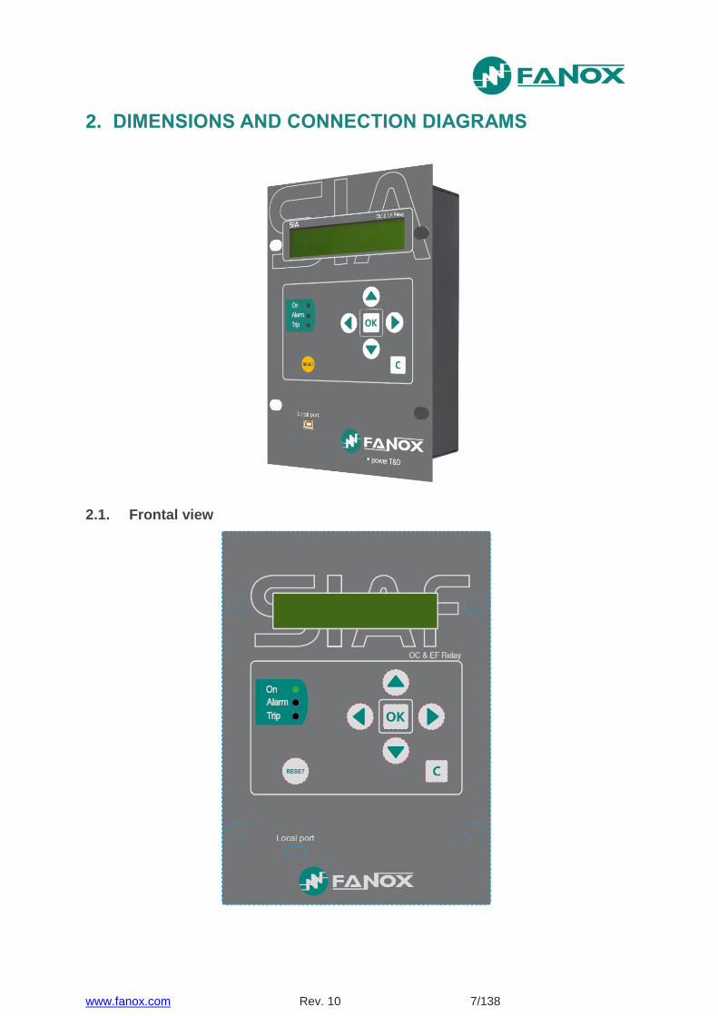
2. DIMENSIONS AND CONNECTION DIAGRAMS
2.1. Frontal view
www.fanox.com Rev. 10 8/138
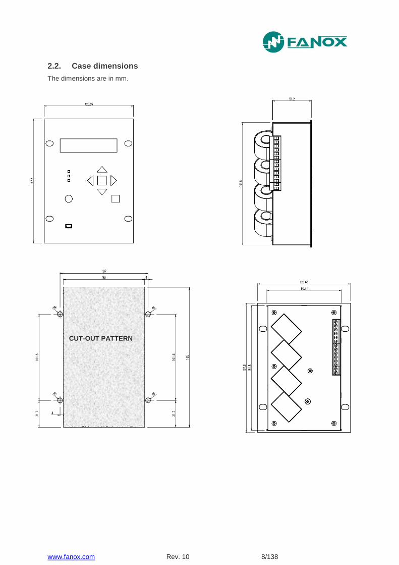
2.2. Case dimensions
The dimensions are in mm.
CUT-OUT PATTERN

www.fanox.com Rev. 10 9/138
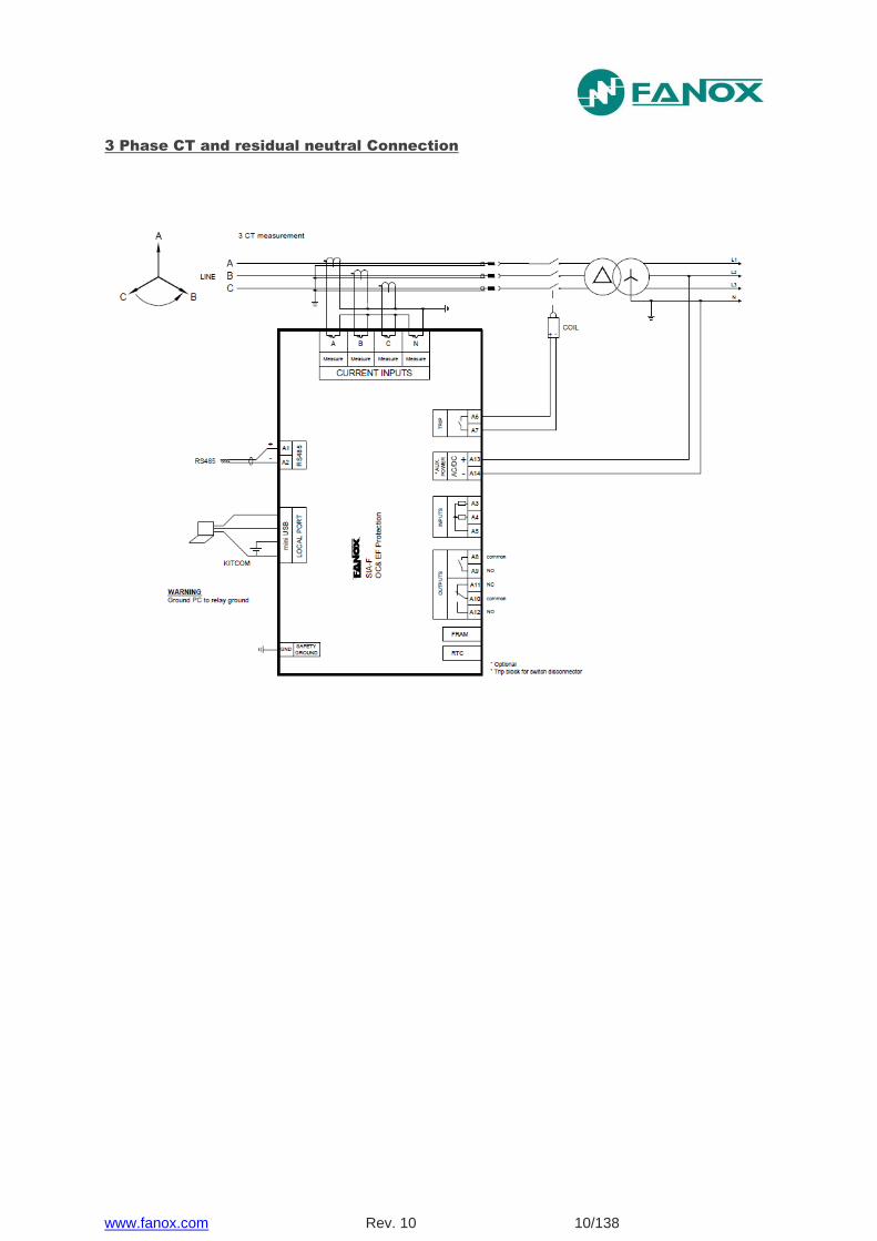
2.3. Connection diagram
3 Phase CT and neutral CT Connection
www.fanox.com Rev. 10 11/138
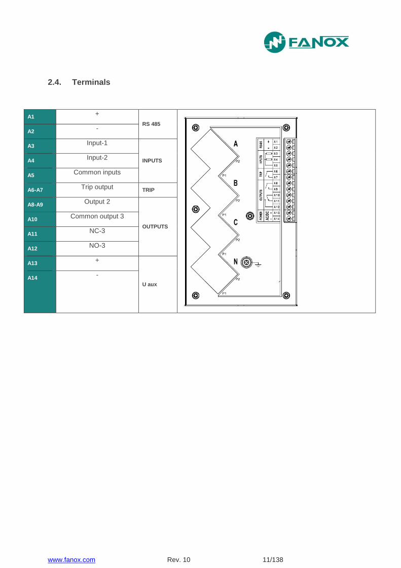
2.4. Terminals
A1 +
RS 485
A2 -
A3 Input-1
INPUTS A4 Input-2
A5 Common inputs
A6-A7 Trip output
TRIP
A8-A9 Output 2
OUTPUTS
A10 Common output 3
A11 NC-3
A12 NO-3
A13 +
U aux
A14 -
www.fanox.com Rev. 10 12/138
3. DESCRIPTION
3.1. Introduction
Worldwide, the energy sector is currently undergoing a profound change as a result of high levels of energy demand; more distribution lines and advanced supervision systems are required. Given the need for creating intelligent infrastructure, FANOX has developed the SIA family of products to carry out this function.
The family of SIA relays is designed to protect the secondary transformation and distribution centers of electricity grids. Protection features include protection against instantaneous and inverse time overcurrent (for the phases and the neutral), and it also has external trip support (temperature, pressure, etc.) depending on the characteristics of each model.
The protection functions can be enabled selectively by using both the front panel and the communications links to the SICom program, allowing for precise coordination with other equipment.
Additional benefits include that all of the models have been designed to be supplied from an external battery. This is aimed at facilitating event management and the commissioning of centres, as well as allowing it to operate properly under adverse conditions.
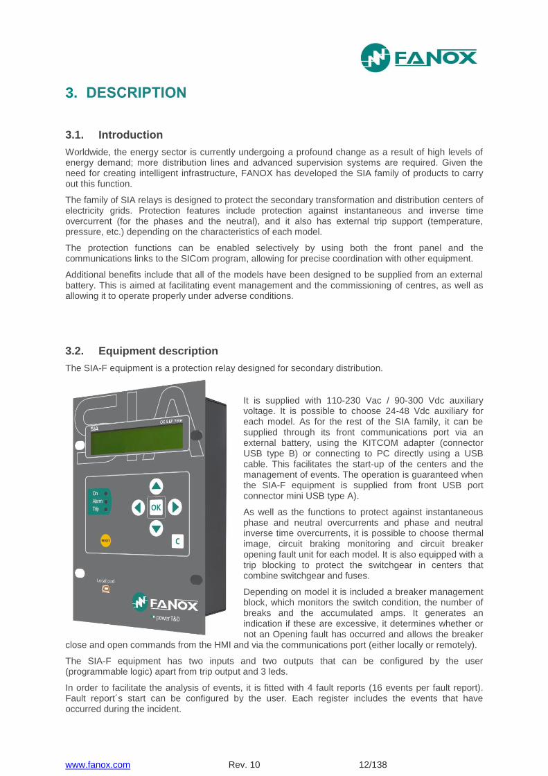
3.2. Equipment description
The SIA-F equipment is a protection relay designed for secondary distribution.
It is supplied with 110-230 Vac / 90-300 Vdc auxiliary voltage. It is possible to choose 24-48 Vdc auxiliary for each model. As for the rest of the SIA family, it can be supplied through its front communications port via an external battery, using the KITCOM adapter (connector USB type B) or connecting to PC directly using a USB cable. This facilitates the start-up of the centers and the management of events. The operation is guaranteed when the SIA-F equipment is supplied from front USB port connector mini USB type A).
As well as the functions to protect against instantaneous phase and neutral overcurrents and phase and neutral inverse time overcurrents, it is possible to choose thermal image, circuit braking monitoring and circuit breaker opening fault unit for each model. It is also equipped with a trip blocking to protect the switchgear in centers that combine switchgear and fuses.
Depending on model it is included a breaker management block, which monitors the switch condition, the number of breaks and the accumulated amps. It generates an indication if these are excessive, it determines whether or not an Opening fault has occurred and allows the breaker
close and open commands from the HMI and via the communications port (either locally or remotely).
The SIA-F equipment has two inputs and two outputs that can be configured by the user (programmable logic) apart from trip output and 3 leds.
In order to facilitate the analysis of events, it is fitted with 4 fault reports (16 events per fault report). Fault report´s start can be configured by the user. Each register includes the events that have occurred during the incident.
www.fanox.com Rev. 10 13/138
The SIA-F equipment is housed in a metal box with galvanic isolation on all of its measurement or digital inputs and outputs (with the exception of ports for communications and battery power supply, as these are sporadic connections). This allows the equipment to have the best possible level of electromagnetic compatibility, both in terms of emission of, and immunity from, radiated and conducted interferences. These levels are the same as those established for primary substations.
The equipment has a LCD with two lines and twenty columns and a membrane keyboard with six buttons. These allow the display of the equipment state, the current measurements in the primary and the events or incidents associated with the equipment, and adjustments to be made to the protection criteria. These events are saved in a non-volatile memory to conserve them in case of power failures.
There are three configurable LED indicators on the front of the SIA-F equipment. By default, these indicate if the equipment is ready (LED ON), if an alarm has happened (LED ALARM) or if a trip has happened (LED TRIP). The equipment has storage for up to 200 events, allowing any recorded incidents to be analyzed. All SIA-F models are equipped with a real-time clock (RTC).
Current measurements are performed using RMS values, with ±2% accuracy in a band of ± 20% when compared with rated current and ±4% in the rest of the range. Standard 5 A and 1 A current transformers (CTs) are used.
The equipment has two communication ports: a front port (connector mini USB type A) and a rear port (RS485). The front port allows a PC to be connected, which can be used to monitor the equipment using the SICom communications program (supplied by FANOX). Front port can be used to power the equipment by using a USB cable which can be directly connected with PC. The rear port RS485 allows the equipment to be integrated as part of a system (SCADA). The ModBus RTU protocol is used in both ports. Setting-up a session allows four levels of access to be set up with passwords that can be configured by the user.
The protection functions provided, easy-to-use interface, low amount of maintenance and simple integration make the SIA-F a precise and practical solution for protecting both industrial and public electrical grids and transformation and distribution centers. The protection offered by the SIA-F against earth faults is sensitive enough to be used in electric systems where the earth fault current is low. It can be set to 0.1 times the rated neutral current and, depending on the model, the rated neutral current can go as low as 0.1 A.
www.fanox.com Rev. 10 14/138
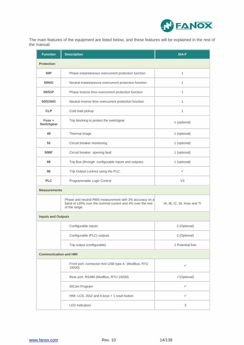
The main features of the equipment are listed below, and these features will be explained in the rest of the manual:
Function Description SIA-F
Protection
50P Phase instantaneous overcurrent protection function 1
50N/G Neutral instantaneous overcurrent protection function 1
50/51P Phase inverse time overcurrent protection function 1
50/51N/G Neutral inverse time overcurrent protection function 1
CLP Cold load pickup 1
Fuse + Switchgear
Trip blocking to protect the switchgear 1 (optional)
49 Thermal image 1 (optional)
52 Circuit breaker monitoring 1 (optional)
50BF Circuit breaker opening fault 1 (optional)
68 Trip Bus (through configurable inputs and outputs) 1 (optional)
86 Trip Output Lockout using the PLC.
PLC Programmable Logic Control V3
Measurements
Phase and neutral RMS measurement with 2% accuracy on a band of ±20% over the nominal current and 4% over the rest of the range.
IA, IB, IC, IN, Imax and TI
Inputs and Outputs
Configurable Inputs 2 (Optional)
Configurable (PLC) outputs 2 (Optional)
Trip output (configurable) 1 Potential free
Communication and HMI
Front port: connector mini USB type A (ModBus, RTU 19200)
Rear port: RS485 (ModBus, RTU 19200) (Optional)
SICom Program
HMI: LCD, 20x2 and 6 keys + 1 reset button
LED Indicators 3
www.fanox.com Rev. 10 15/138
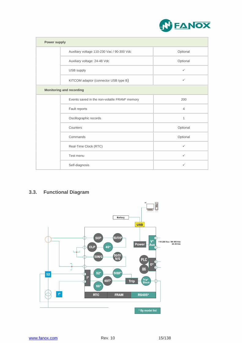
Power supply
Auxiliary voltage 110-230 Vac / 90-300 Vdc Optional
Auxiliary voltage: 24-48 Vdc Optional
USB supply
KITCOM adaptor (connector USB type B)
Monitoring and recording
Events saved in the non-volatile FRAM* memory 200
Fault reports 4
Oscillographic records 1
Counters Optional
Commands Optional
Real-Time Clock (RTC)
Test menu
Self-diagnosis
3.3. Functional Diagram
www.fanox.com Rev. 10 16/138
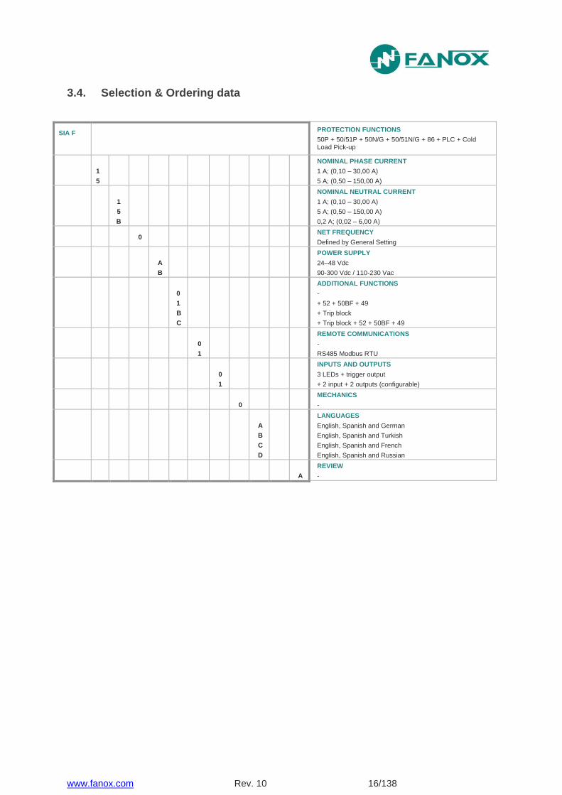
3.4. Selection & Ordering data
SIA F PROTECTION FUNCTIONS
50P + 50/51P + 50N/G + 50/51N/G + 86 + PLC + Cold Load Pick-up
1
5
NOMINAL PHASE CURRENT
1 A; (0,10 – 30,00 A)
5 A; (0,50 – 150,00 A)
1
5
B
NOMINAL NEUTRAL CURRENT
1 A; (0,10 – 30,00 A)
5 A; (0,50 – 150,00 A)
0,2 A; (0,02 – 6,00 A)
0
NET FREQUENCY
Defined by General Setting
A
B
POWER SUPPLY
24–48 Vdc
90-300 Vdc / 110-230 Vac
0
1
B
C
ADDITIONAL FUNCTIONS
-
+ 52 + 50BF + 49
+ Trip block
+ Trip block + 52 + 50BF + 49
0
1
REMOTE COMMUNICATIONS
-
RS485 Modbus RTU
0
1
INPUTS AND OUTPUTS
3 LEDs + trigger output
+ 2 input + 2 outputs (configurable)
0
MECHANICS
-
A
B
C
D
LANGUAGES
English, Spanish and German
English, Spanish and Turkish
English, Spanish and French
English, Spanish and Russian
A
REVIEW
-
www.fanox.com Rev. 10 17/138
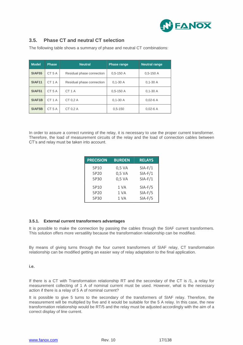
3.5. Phase CT and neutral CT selection
The following table shows a summary of phase and neutral CT combinations:
Model Phase Neutral Phase range Neutral range
SIAF55 CT 5 A Residual phase connection 0,5-150 A 0,5-150 A
SIAF11 CT 1 A Residual phase connection 0,1-30 A 0,1-30 A
SIAF51 CT 5 A CT 1 A 0,5-150 A 0,1-30 A
SIAF1B CT 1 A CT 0,2 A 0,1-30 A 0,02-6 A
SIAF5B CT 5 A CT 0,2 A 0,5-150 0,02-6 A
In order to assure a correct running of the relay, it is necessary to use the proper current transformer. Therefore, the load of measurement circuits of the relay and the load of connection cables between CT’s and relay must be taken into account.
3.5.1. External current transformers advantages
It is possible to make the connection by passing the cables through the SIAF current transformers. This solution offers more versatility because the transformation relationship can be modified.
By means of giving turns through the four current transformers of SIAF relay, CT transformation relationship can be modified getting an easier way of relay adaptation to the final application.
i.e.
If there is a CT with Transformation relationship RT and the secondary of the CT is /1, a relay for measurement collecting of 1 A of nominal current must be used. However, what is the necessary action if there is a relay of 5 A of nominal current?
It is possible to give 5 turns to the secondary of the transformers of SIAF relay. Therefore, the measurement will be multiplied by five and it would be suitable for the 5 A relay. In this case, the new transformation relationship would be RT/5 and the relay must be adjusted accordingly with the aim of a correct display of line current.
PRECISION BURDEN RELAYS
5P10 5P20 5P30
0,5 VA 0,5 VA 0,5 VA
SIA-F/1 SIA-F/1 SIA-F/1
5P10 5P20 5P30
1 VA 1 VA 1 VA
SIA-F/5 SIA-F/5 SIA-F/5
www.fanox.com Rev. 10 18/138
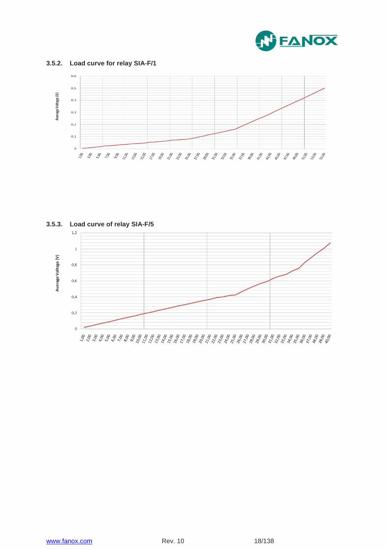
3.5.2. Load curve for relay SIA-F/1
3.5.3. Load curve of relay SIA-F/5
www.fanox.com Rev. 10 19/138
4. PROTECTION FUNCTIONS
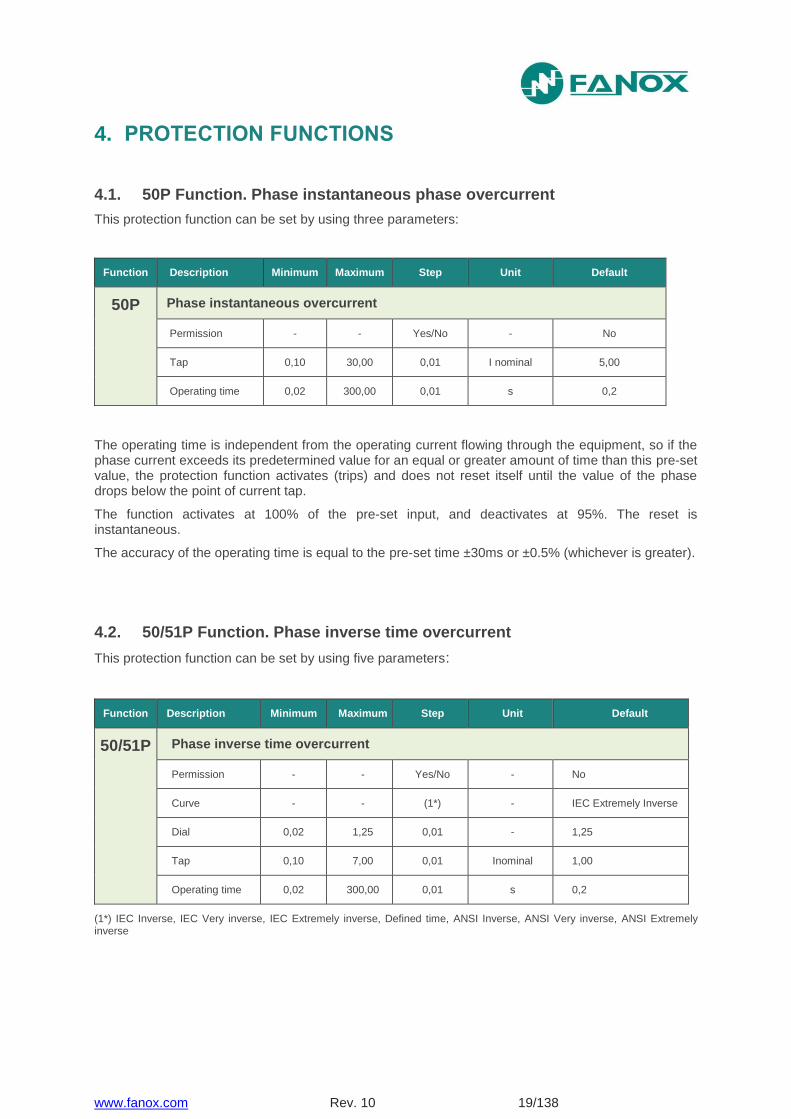
4.1. 50P Function. Phase instantaneous phase overcurrent
This protection function can be set by using three parameters:
Function Description Minimum Maximum Step Unit Default
50P Phase instantaneous overcurrent
Permission - - Yes/No - No
Tap 0,10 30,00 0,01 I nominal 5,00
Operating time 0,02 300,00 0,01 s 0,2
The operating time is independent from the operating current flowing through the equipment, so if the phase current exceeds its predetermined value for an equal or greater amount of time than this pre-set value, the protection function activates (trips) and does not reset itself until the value of the phase drops below the point of current tap.
The function activates at 100% of the pre-set input, and deactivates at 95%. The reset is instantaneous.
The accuracy of the operating time is equal to the pre-set time ±30ms or ±0.5% (whichever is greater).
4.2. 50/51P Function. Phase inverse time overcurrent
This protection function can be set by using five parameters:
Function Description Minimum Maximum Step Unit Default
50/51P Phase inverse time overcurrent
Permission - - Yes/No - No
Curve - - (1*) - IEC Extremely Inverse
Dial 0,02 1,25 0,01 - 1,25
Tap 0,10 7,00 0,01 Inominal 1,00
Operating time 0,02 300,00 0,01 s 0,2
(1*) IEC Inverse, IEC Very inverse, IEC Extremely inverse, Defined time, ANSI Inverse, ANSI Very inverse, ANSI Extremely inverse
www.fanox.com Rev. 10 20/138
If the option "Defined time" is selected for the curve setting, the unit behaves like an instantaneous overcurrent unit. In this case, the unit operating time is set by the parameter "Operating time".
If a curve is selected for the curve setting, the operating time depends on the curve, dial and tap settings.
If the unit operates with defined time, the function is activated at 100% of the set tap value, and it deactivates at 95%.
If the unit operates with a curve, the function is activated at 110% of the set tap value, and it deactivates at 100%.
The reset is instantaneous in both cases.
The activation time is accurate to ±5% or ±30ms, whichever is greater, of the theoretical activation time.
The curves used are IEC 60255-151 or ANSI-IEEE, which are described in the "Curves" section.
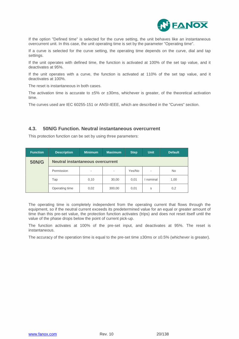
4.3. 50N/G Function. Neutral instantaneous overcurrent
This protection function can be set by using three parameters:
Function Description Minimum Maximum Step Unit Default
50N/G Neutral instantaneous overcurrent
Permission - - Yes/No - No
Tap 0,10 30,00 0,01 I nominal 1,00
Operating time 0,02 300,00 0,01 s 0,2
The operating time is completely independent from the operating current that flows through the equipment, so if the neutral current exceeds its predetermined value for an equal or greater amount of time than this pre-set value, the protection function activates (trips) and does not reset itself until the value of the phase drops below the point of current pick-up.
The function activates at 100% of the pre-set input, and deactivates at 95%. The reset is instantaneous.
The accuracy of the operation time is equal to the pre-set time ±30ms or ±0.5% (whichever is greater).
www.fanox.com Rev. 10 21/138
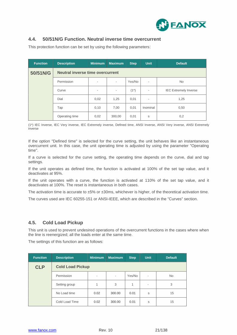
4.4. 50/51N/G Function. Neutral inverse time overcurrent
This protection function can be set by using the following parameters:
Function Description Minimum Maximum Step Unit Default
50/51N/G Neutral inverse time overcurrent
Permission - - Yes/No - No
Curve - - (1*) - IEC Extremely Inverse
Dial 0,02 1,25 0,01 - 1,25
Tap 0,10 7,00 0,01 Inominal 0,50
Operating time 0,02 300,00 0,01 s 0,2
(1*) IEC Inverse, IEC Very inverse, IEC Extremely inverse, Defined time, ANSI Inverse, ANSI Very inverse, ANSI Extremely inverse
If the option "Defined time" is selected for the curve setting, the unit behaves like an instantaneous overcurrent unit. In this case, the unit operating time is adjusted by using the parameter "Operating time".
If a curve is selected for the curve setting, the operating time depends on the curve, dial and tap settings.
If the unit operates as defined time, the function is activated at 100% of the set tap value, and it deactivates at 95%.
If the unit operates with a curve, the function is activated at 110% of the set tap value, and it deactivates at 100%. The reset is instantaneous in both cases.
The activation time is accurate to ±5% or ±30ms, whichever is higher, of the theoretical activation time.
The curves used are IEC 60255-151 or ANSI-IEEE, which are described in the "Curves" section.
4.5. Cold Load Pickup
This unit is used to prevent undesired operations of the overcurrent functions in the cases where when the line is reenergized; all the loads enter at the same time.
The settings of this function are as follows:
Function Description Minimum Maximum Step Unit Default
CLP Cold Load Pickup
Permission - - Yes/No - No
Setting group 1 3 1 - 3
No Load time 0.02 300.00 0.01 s 15
Cold Load Time 0.02 300.00 0.01 s 15
www.fanox.com Rev. 10 22/138
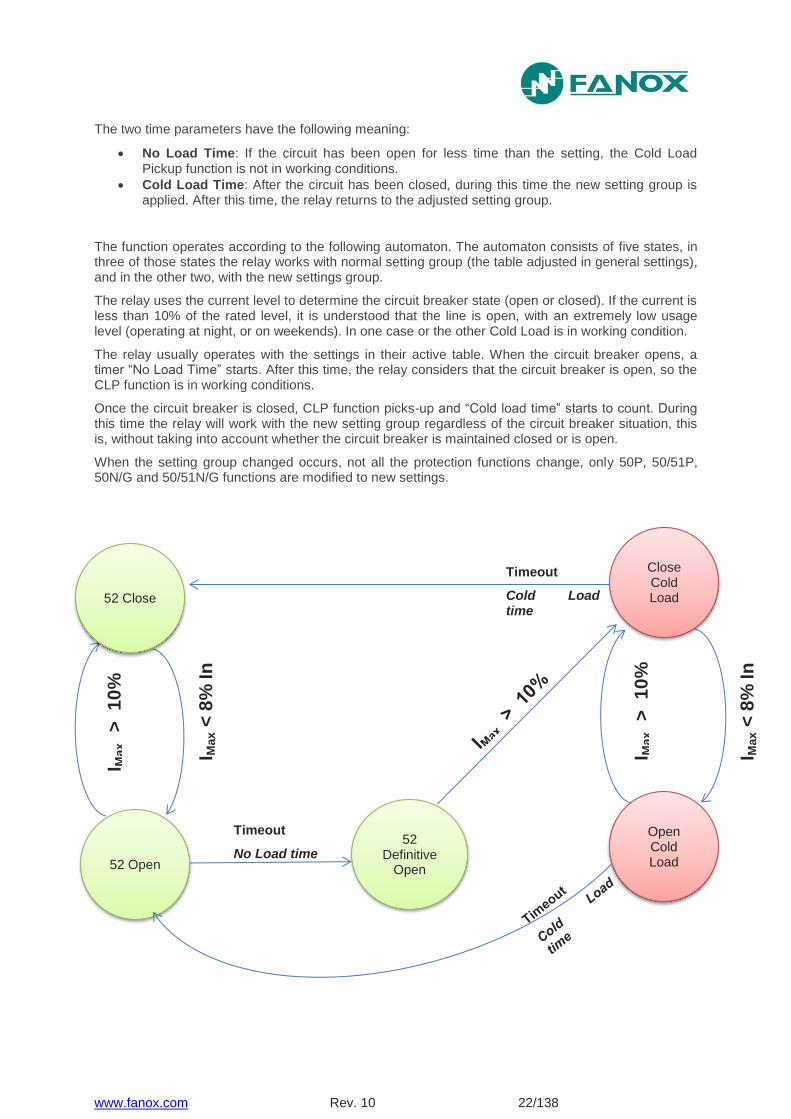
The two time parameters have the following meaning:
No Load Time: If the circuit has been open for less time than the setting, the Cold Load Pickup function is not in working conditions.
Cold Load Time: After the circuit has been closed, during this time the new setting group is applied. After this time, the relay returns to the adjusted setting group.
The function operates according to the following automaton. The automaton consists of five states, in three of those states the relay works with normal setting group (the table adjusted in general settings), and in the other two, with the new settings group.
The relay uses the current level to determine the circuit breaker state (open or closed). If the current is less than 10% of the rated level, it is understood that the line is open, with an extremely low usage level (operating at night, or on weekends). In one case or the other Cold Load is in working condition.
The relay usually operates with the settings in their active table. When the circuit breaker opens, a timer “No Load Time” starts. After this time, the relay considers that the circuit breaker is open, so the CLP function is in working conditions.
Once the circuit breaker is closed, CLP function picks-up and “Cold load time” starts to count. During this time the relay will work with the new setting group regardless of the circuit breaker situation, this is, without taking into account whether the circuit breaker is maintained closed or is open.
When the setting group changed occurs, not all the protection functions change, only 50P, 50/51P, 50N/G and 50/51N/G functions are modified to new settings.
Timeout
No Load time
Timeout
Cold Load time
I Max <
8%
In
I Max <
8%
In
52 Open
52 Close
52 Definitive
Open
Close Cold Load
Open Cold Load
I Max
>
10
%
In I M
ax
>
10
%
In
www.fanox.com Rev. 10 23/138
4.6. Trip block protection for the switchgear
Some transformation centers use a combination of switchgear and fuses for cutting out. Switchgears have a limited opening current. As a result, the fuses are responsible for cutting out the circuit for high current short circuits, as the switchgear would be destroyed if opened in this situation. In order to deal with these situations, tripping is blocked when the phase current exceeds a pre-set value.
Group Description Minimum Maximum Step Unit Default
Trip block protection for the switchgear
Blocking - - Yes/No - Yes
Blocking limit 1,50 20,00 0,01 I nominal 7,00
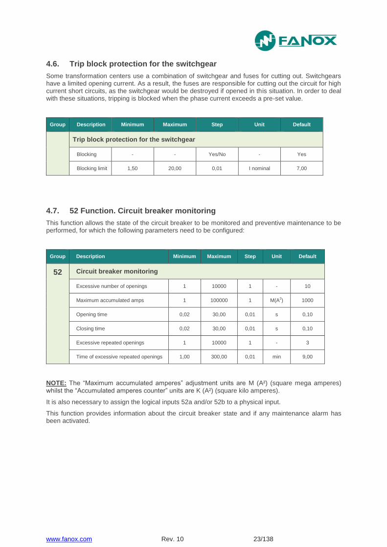
4.7. 52 Function. Circuit breaker monitoring
This function allows the state of the circuit breaker to be monitored and preventive maintenance to be performed, for which the following parameters need to be configured:
Group Description Minimum Maximum Step Unit Default
52 Circuit breaker monitoring
Excessive number of openings 1 10000 1 - 10
Maximum accumulated amps 1 100000 1 M(A2) 1000
Opening time 0,02 30,00 0,01 s 0,10
Closing time 0,02 30,00 0,01 s 0,10
Excessive repeated openings 1 10000 1 - 3
Time of excessive repeated openings 1,00 300,00 0,01 min 9,00
NOTE: The “Maximum accumulated amperes” adjustment units are M (A²) (square mega amperes) whilst the “Accumulated amperes counter” units are K (A²) (square kilo amperes).
It is also necessary to assign the logical inputs 52a and/or 52b to a physical input.
This function provides information about the circuit breaker state and if any maintenance alarm has been activated.
www.fanox.com Rev. 10 24/138
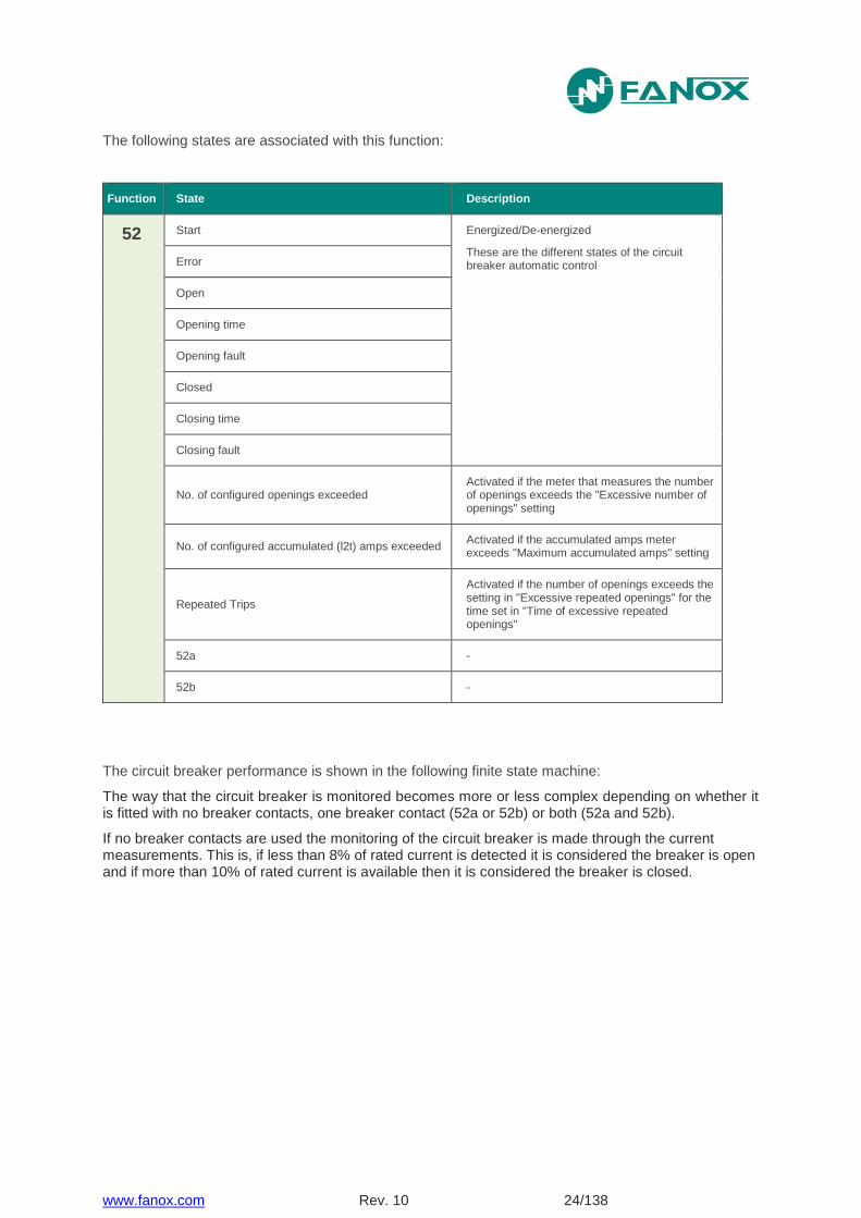
The following states are associated with this function:
Function State Description
52 Start Energized/De-energized
These are the different states of the circuit breaker automatic control Error
Open
Opening time
Opening fault
Closed
Closing time
Closing fault
No. of configured openings exceeded Activated if the meter that measures the number of openings exceeds the "Excessive number of openings" setting
No. of configured accumulated (l2t) amps exceeded Activated if the accumulated amps meter exceeds "Maximum accumulated amps" setting
Repeated Trips
Activated if the number of openings exceeds the setting in "Excessive repeated openings" for the time set in "Time of excessive repeated openings"
52a -
52b -
The circuit breaker performance is shown in the following finite state machine:
The way that the circuit breaker is monitored becomes more or less complex depending on whether it is fitted with no breaker contacts, one breaker contact (52a or 52b) or both (52a and 52b).
If no breaker contacts are used the monitoring of the circuit breaker is made through the current measurements. This is, if less than 8% of rated current is detected it is considered the breaker is open and if more than 10% of rated current is available then it is considered the breaker is closed.
www.fanox.com Rev. 10 25/138
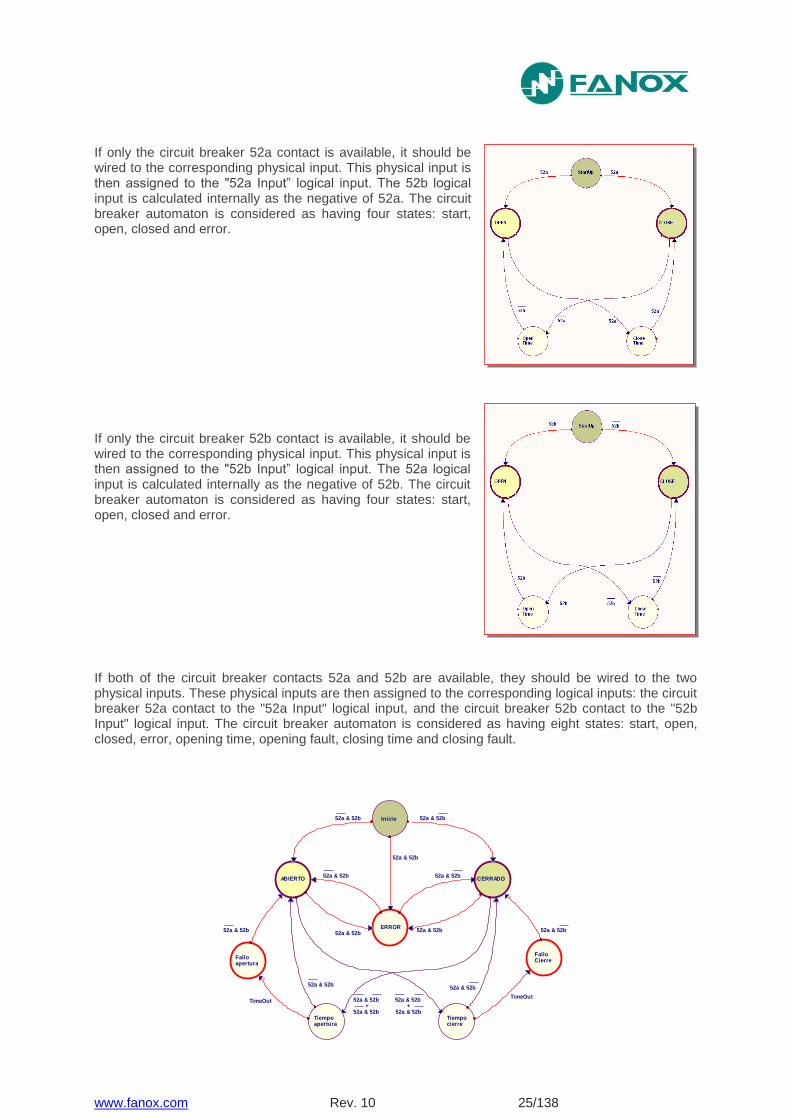
If only the circuit breaker 52a contact is available, it should be wired to the corresponding physical input. This physical input is then assigned to the "52a Input” logical input. The 52b logical input is calculated internally as the negative of 52a. The circuit breaker automaton is considered as having four states: start, open, closed and error.
If only the circuit breaker 52b contact is available, it should be wired to the corresponding physical input. This physical input is then assigned to the "52b Input” logical input. The 52a logical input is calculated internally as the negative of 52b. The circuit breaker automaton is considered as having four states: start, open, closed and error.
If both of the circuit breaker contacts 52a and 52b are available, they should be wired to the two physical inputs. These physical inputs are then assigned to the corresponding logical inputs: the circuit breaker 52a contact to the "52a Input" logical input, and the circuit breaker 52b contact to the "52b Input" logical input. The circuit breaker automaton is considered as having eight states: start, open, closed, error, opening time, opening fault, closing time and closing fault.
Inicio
ABIERTO CERRADO
52a & 52b
TimeOutTimeOut
FalloCierre
ERROR
Tiempo apertura
Tiempocierre
Falloapertura
52a & 52b
52a & 52b
52a & 52b
52a & 52b
52a & 52b
52a & 52b
52a & 52b 52a & 52b
52a & 52b
52a & 52b 52a & 52b
52a & 52b
52a & 52b52a & 52b+ +
www.fanox.com Rev. 10 26/138
4.7.1. Circuit breaker opening and closing commands
The circuit breaker opening and closing commands are implemented. These commands can be executed from the HMI command menu or through communications.
For the commands to have an effect, they should be assigned to the corresponding outputs. The "Open circuit breaker" and "Close circuit breaker" bits are assigned to their corresponding outputs in the "CONTROL" state group in the state menu.
4.7.2. Counter to register the number of openings
The SIA-F equipment is fitted with a counter that registers the number of times the circuit breaker opens.
This meter is associated with the "Maximum number of openings" setting. When the number of openings exceeds this pre-set value, the "Excessive number of openings" state is activated and its corresponding event is generated.
This counter reading can be set to any value within its range from the HMI or by communications.
4.7.3. Counter to register the accumulated amps: I2t
An accumulated amps counter is also fitted. This counter accumulates the amps that are cleared by the circuit breaker by opening.
When the circuit breaker opens, the maximum number of primary amps in any of the phases is detected. This reading is squared and divided by 1000 and then rescaled to KA and accumulated. If the current detected in the opening is less than the rated current, the rated current value is used for the accumulation.
It is used in conjunction with the metering of the number of openings, to measure the circuit breaker aging process.
Since primary amps are being accumulated, it is essential to correctly adjust the phase CT transformation ratio.
The "Maximum accumulated amps" setting is associated with this counter. When the number of accumulated amps exceeds this pre-set value, the "Excessive accumulated amps" state is activated and its corresponding event is generated.
This counter reading can be set to any value from within its range from the HMI or by communications.
4.7.4. Excessive openings per time
As well as counting the number of times the circuit breaker opens, the SIA-F equipment sets up a time window and the maximum number of openings allowed during this time. Both parameters can be adjusted.
When this number is exceeded, the "Repeated Trips" state is activated and its corresponding event is generated.
www.fanox.com Rev. 10 27/138
4.8. 49 Function. Thermal Image Protection
Thermal image is a measure of heating and cooling of an electric machine. Unlike overcurrent protection, do not start counting the time when it detects a fault, but is continuously determining the thermal state of the machine that monitors. The trip time depends on the thermal constants adjusted, the current flowing and the prior thermal state of the machine.
The thermal image is calculated based on the following equation:
θ = 100 x (I/It)2 x (1 – e-t/ζ) + θ’0 x e-t/ζ
Where:
I, maximum R.M.S. current of three phases
It, adjusted tap current
ζ, thermal constant
θ’0, initial thermal state
The trip time is given by the equation:
t = ζ x ln x {[(I/It) 2 – (θ’0 / 100)] / [(I/It)
2 - 1]}
The accuracy of the tripping time is ±5% or ± 2 s (the greatest of both values) the theoretical time.
The algorithm uses the maximum of the three phase currents. If the maximum is greater than 15% of the adjusted tap, heating thermal constant is applied. If the maximum is less than 15% of the adjusted tap cooling thermal constant is taken into account.
The overload function trips when the thermal image reaches the value of 100%. This value is reached in time when the current flowing is equal to the function adjusted in thermal function.
It provides an adjustable level of thermal imaging to generate an alarm. If the trip occurs, the function of overload is reset when the thermal image falls below the set alarm level.
As the current measurement algorithm used is R.M.S., in the thermal model is taken into account the heat produced by the harmonics.
This protection function is adjusted by setting five different parameters:
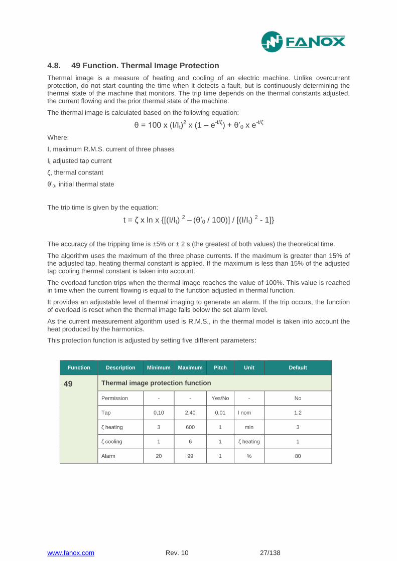
Function Description Minimum Maximum Pitch Unit Default
49 Thermal image protection function
Permission - - Yes/No - No
Tap 0,10 2,40 0,01 I nom 1,2
ζ heating 3 600 1 min 3
ζ cooling 1 6 1 ζ heating 1
Alarm 20 99 1 % 80
www.fanox.com Rev. 10 28/138
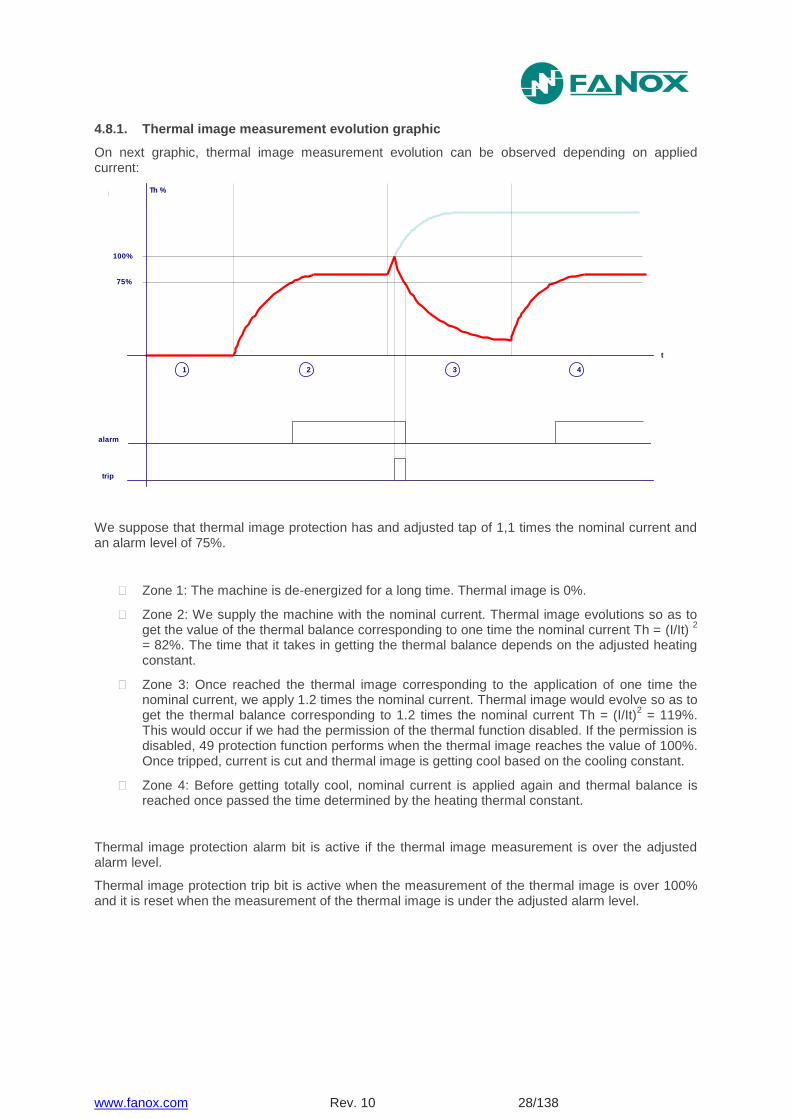
4.8.1. Thermal image measurement evolution graphic
On next graphic, thermal image measurement evolution can be observed depending on applied current:
We suppose that thermal image protection has and adjusted tap of 1,1 times the nominal current and an alarm level of 75%.
Zone 1: The machine is de-energized for a long time. Thermal image is 0%.
Zone 2: We supply the machine with the nominal current. Thermal image evolutions so as to get the value of the thermal balance corresponding to one time the nominal current Th = (I/It)
2
= 82%. The time that it takes in getting the thermal balance depends on the adjusted heating constant.
Zone 3: Once reached the thermal image corresponding to the application of one time the nominal current, we apply 1.2 times the nominal current. Thermal image would evolve so as to get the thermal balance corresponding to 1.2 times the nominal current Th = (I/It)
2 = 119%.
This would occur if we had the permission of the thermal function disabled. If the permission is disabled, 49 protection function performs when the thermal image reaches the value of 100%. Once tripped, current is cut and thermal image is getting cool based on the cooling constant.
Zone 4: Before getting totally cool, nominal current is applied again and thermal balance is reached once passed the time determined by the heating thermal constant.
Thermal image protection alarm bit is active if the thermal image measurement is over the adjusted alarm level.
Thermal image protection trip bit is active when the measurement of the thermal image is over 100% and it is reset when the measurement of the thermal image is under the adjusted alarm level.
Th %
t
100%
1 2 3 4
75%
alarm
trip
www.fanox.com Rev. 10 29/138
4.8.2. Thermal image with memory
Thermal image is stored in non-volatile RAM memory periodically every second. By this way, though the relay loses the power supply, it will keep the thermal state of the machine.
4.8.3. Thermal image measurement display. Reset.
Thermal image measurement can be displayed on Measurement menu and Counters menu.
Display is possible in Measurement menu. Display and thermal image value reset is possible in Counters menu.
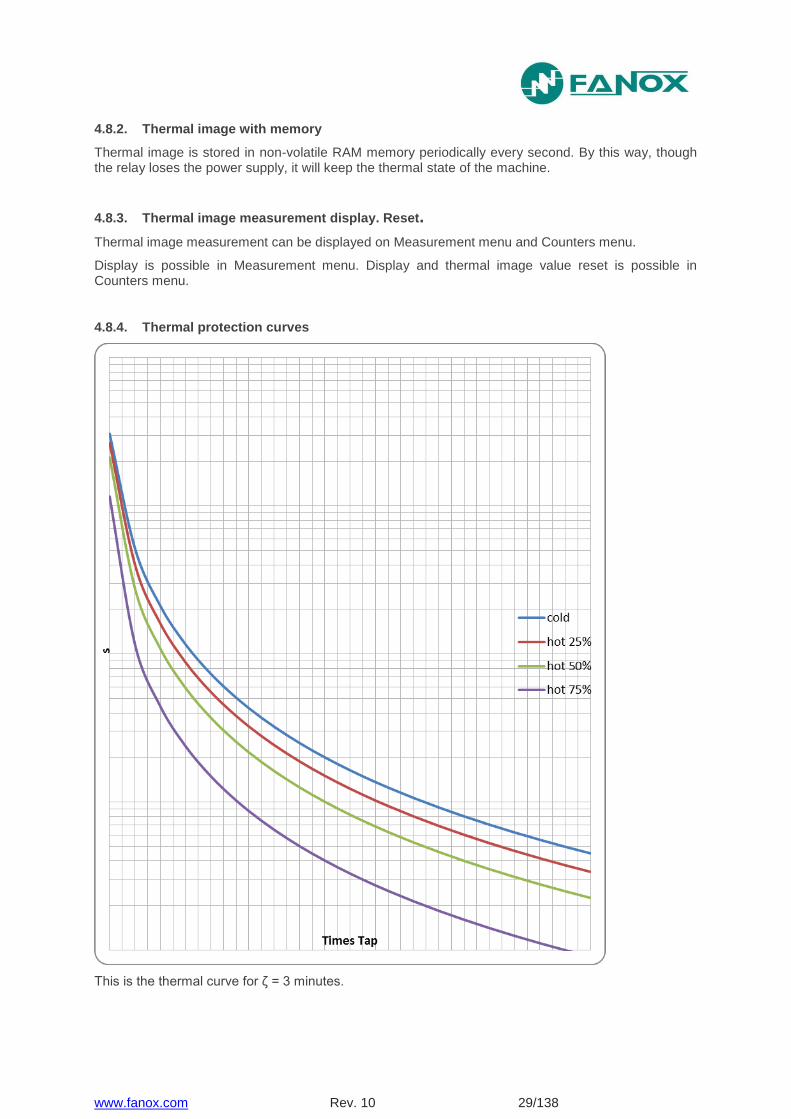
4.8.4. Thermal protection curves
This is the thermal curve for ζ = 3 minutes.
www.fanox.com Rev. 10 30/138
4.9. 50BF Function. Circuit Breaker opening fault
The settings of this function are as follows:
Function Description Minimum Maximum Pitch Unit Default
50BF
Circuit breaker opening fault
Permission - - Yes/No - No
Opening fault time 0,02 1,00 0,01 s 0,2
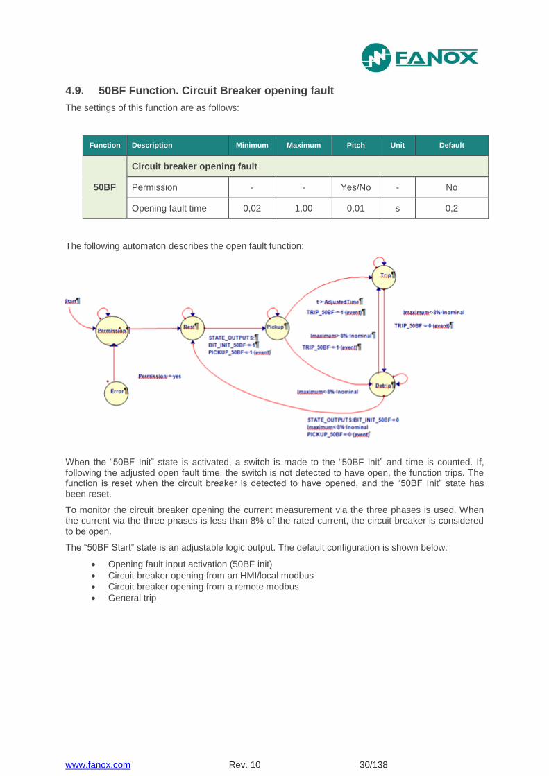
The following automaton describes the open fault function:
When the “50BF Init” state is activated, a switch is made to the "50BF init” and time is counted. If, following the adjusted open fault time, the switch is not detected to have open, the function trips. The function is reset when the circuit breaker is detected to have opened, and the “50BF Init” state has been reset.
To monitor the circuit breaker opening the current measurement via the three phases is used. When the current via the three phases is less than 8% of the rated current, the circuit breaker is considered to be open.
The “50BF Start” state is an adjustable logic output. The default configuration is shown below:
Opening fault input activation (50BF init)
Circuit breaker opening from an HMI/local modbus
Circuit breaker opening from a remote modbus
General trip
www.fanox.com Rev. 10 31/138
4.10. 68 Function. Trip Bus
Optionally, (selectable by model), SIA-F equipment is provide with two outputs and two inputs which can be used for implementing a trip bus (inputs and outputs are configurable).
Trip bus Configuration:
FEEDER RELAY
Output 1: startup of function 50P or 50/51P
Output 2: startup of function 50N/G or 50/51N/G
SUPPLY RELAY
Input 1: block the trip of functions 50P and 50/51P
Input 2: block the trip of functions 50N/G and 50/51N/G
It consists on implementing a trip bus using SIA-F relays.
Relays with feeder functionality active the output 1 when detect the startup of function 50P or 50/51P and active the output 2 when detect the startup of function 50N/G or 50/51N/G.
Relays with supply functionality, block the trip of functions 50P and 50/51P when detect the activation of input 1 and block the trip of functions 50N/G and 50/51N/G when detect the activation of input 2.
The physical connection which is needed to perform is next: outputs 1 of feeder relays must be connected to the input 1 of the supply equipment and outputs 2 of feeder relays must be connected to the input 2 of the supply equipment.
www.fanox.com Rev. 10 32/138
4.11. General Settings
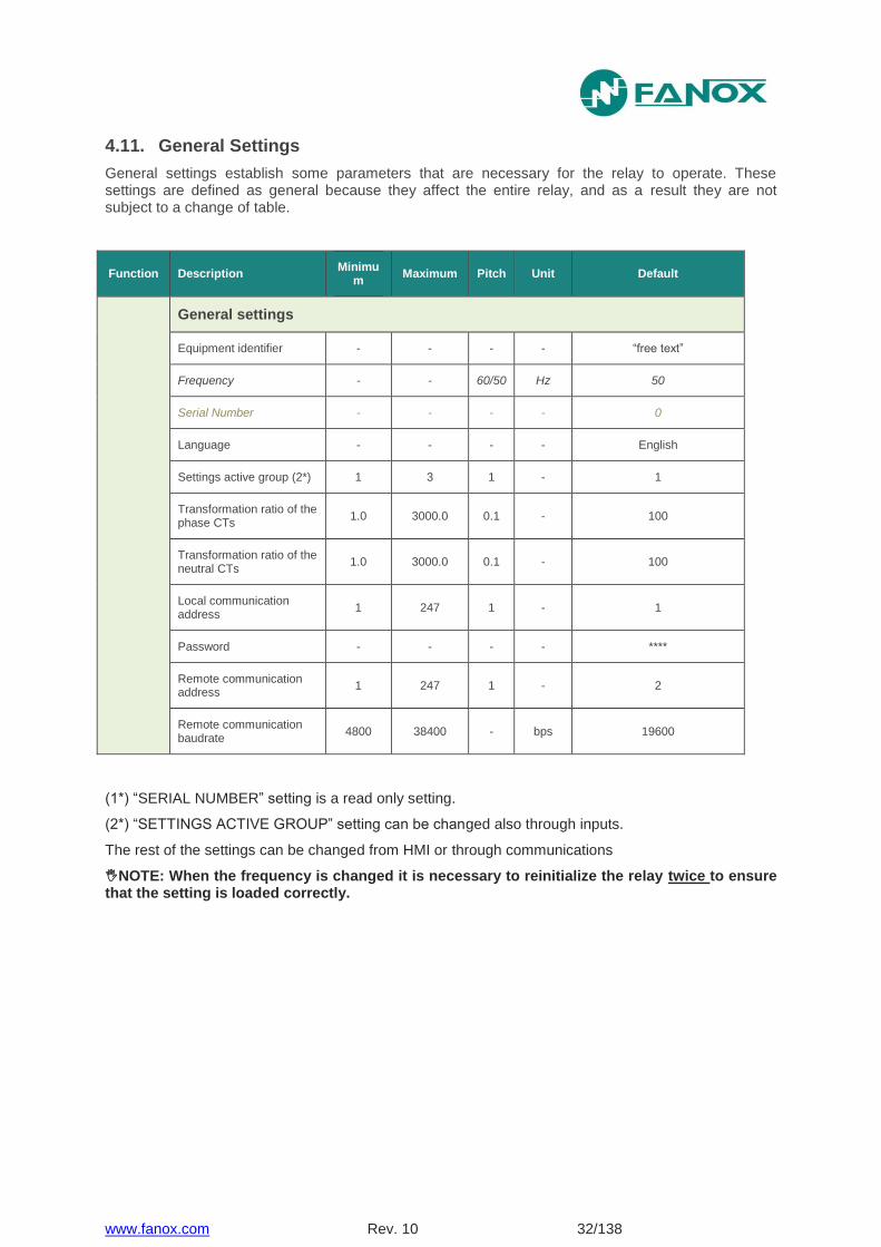
General settings establish some parameters that are necessary for the relay to operate. These settings are defined as general because they affect the entire relay, and as a result they are not subject to a change of table.
Function Description Minimu
m Maximum Pitch Unit Default
General settings
Equipment identifier - - - - “free text”
Frequency - - 60/50 Hz 50
Serial Number - - - - 0
Language - - - - English
Settings active group (2*) 1 3 1 - 1
Transformation ratio of the phase CTs
1.0 3000.0 0.1 - 100
Transformation ratio of the neutral CTs
1.0 3000.0 0.1 - 100
Local communication address
1 247 1 - 1
Password - - - - ****
Remote communication address
1 247 1 - 2
Remote communication baudrate
4800 38400 - bps 19600
(1*) “SERIAL NUMBER” setting is a read only setting.
(2*) “SETTINGS ACTIVE GROUP” setting can be changed also through inputs.
The rest of the settings can be changed from HMI or through communications
NOTE: When the frequency is changed it is necessary to reinitialize the relay twice to ensure that the setting is loaded correctly.
www.fanox.com Rev. 10 33/138
4.12. Setting Group
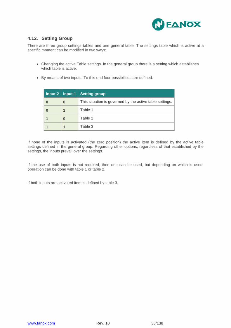
There are three group settings tables and one general table. The settings table which is active at a specific moment can be modified in two ways:
Changing the active Table settings. In the general group there is a setting which establishes which table is active.
By means of two inputs. To this end four possibilities are defined.
Input-2 Input-1 Setting group
0 0 This situation is governed by the active table settings.
0 1 Table 1
1 0 Table 2
1 1 Table 3
If none of the inputs is activated (the zero position) the active item is defined by the active table settings defined in the general group. Regarding other options, regardless of that established by the settings, the inputs prevail over the settings.
If the use of both inputs is not required, then one can be used, but depending on which is used, operation can be done with table 1 or table 2.
If both inputs are activated item is defined by table 3.

www.fanox.com Rev. 10 34/138
4.13. Protection Settings
The SIA-F's settings are listed below with their description, maximums, minimums, units and the values for the factory settings.
Group Description Minimum Maximum Step Unit Default
50P Phases instantaneous overcurrent
Permission - - Yes/No - No
Tap 0,10 30,00 0,01 Inominal 5,00
Operating time 0,02 300,00 0,01 s 0,2
50/51P Phase inverse time overcurrent
Permission - - Yes/No - No
Curve - - (1*) - IEC Extremely inverse
Dial 0,02 1,25 0,01 - 1,25
Tap 0,10 7,00 0,01 I nominal 1,00
Operating time 0,02 300,00 0,01 s 0,2
50N/G Neutral instantaneous overcurrent
Permission - - Yes/No - No
Tap 0,10 30,00 0,01 I nominal 1,00
Operating time 0,02 300,00 0,01 s 0,2
50/51N/G Neutral inverse time overcurrent
Permission - - Yes/No - No
Curve - - (1*) - IEC Extremely inverse
Dial 0,02 1,25 0,01 - 1,25
Tap 0,10 7,00 0,01 I nominal 0,50
Operating time 0,02 300,00 0,01 s 0,2
CLP Cold Load Pickup
Permission - - Yes/No - No
Setting group 1 3 1 - 3
No Load time 0.02 300.00 0.01 s 15
Cold Load Time 0.02 300.00 0.01 s 15
www.fanox.com Rev. 10 35/138
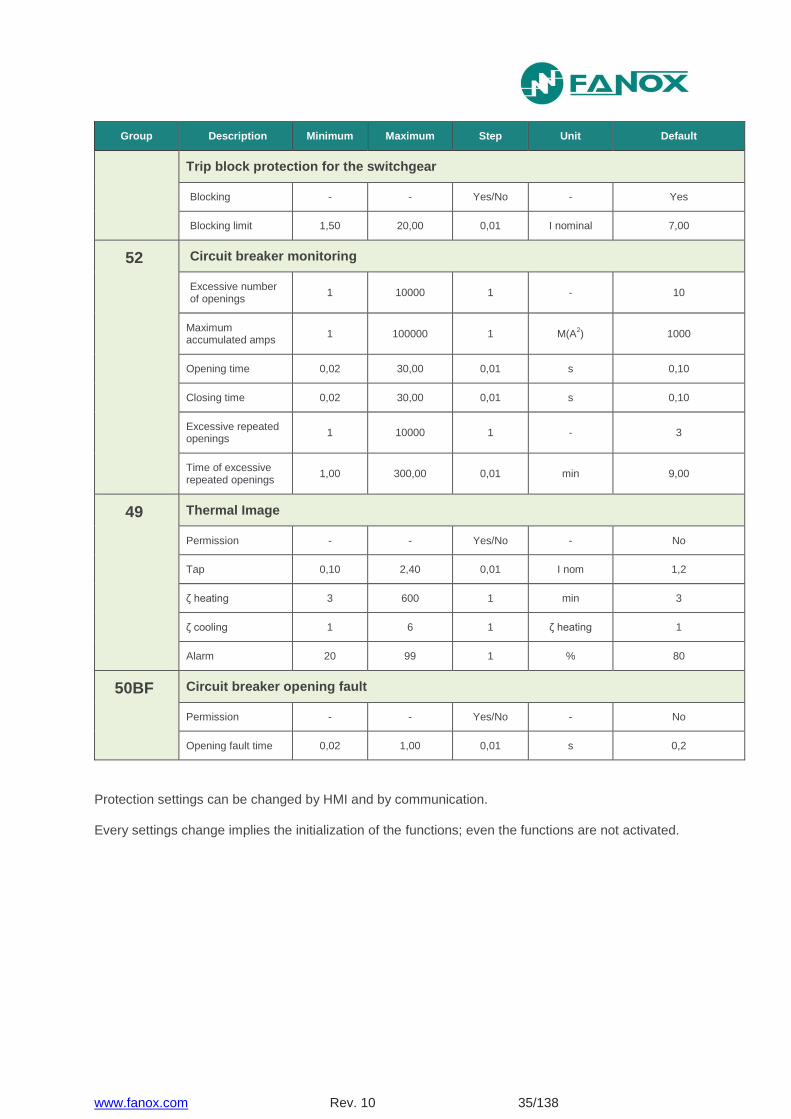
Group Description Minimum Maximum Step Unit Default
Trip block protection for the switchgear
Blocking - - Yes/No - Yes
Blocking limit 1,50 20,00 0,01 I nominal 7,00
52
Circuit breaker monitoring
Excessive number of openings
1 10000 1 - 10
Maximum accumulated amps
1 100000 1 M(A2) 1000
Opening time 0,02 30,00 0,01 s 0,10
Closing time 0,02 30,00 0,01 s 0,10
Excessive repeated openings
1 10000 1 - 3
Time of excessive repeated openings
1,00 300,00 0,01 min 9,00
49 Thermal Image
Permission - - Yes/No - No
Tap 0,10 2,40 0,01 I nom 1,2
ζ heating 3 600 1 min 3
ζ cooling 1 6 1 ζ heating 1
Alarm 20 99 1 % 80
50BF Circuit breaker opening fault
Permission - - Yes/No - No
Opening fault time 0,02 1,00 0,01 s 0,2
Protection settings can be changed by HMI and by communication.
Every settings change implies the initialization of the functions; even the functions are not activated.
www.fanox.com Rev. 10 36/138
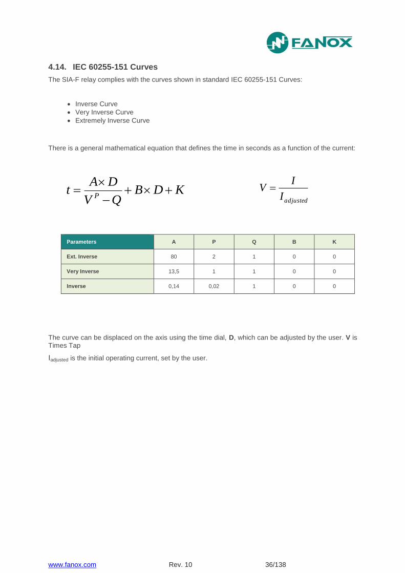
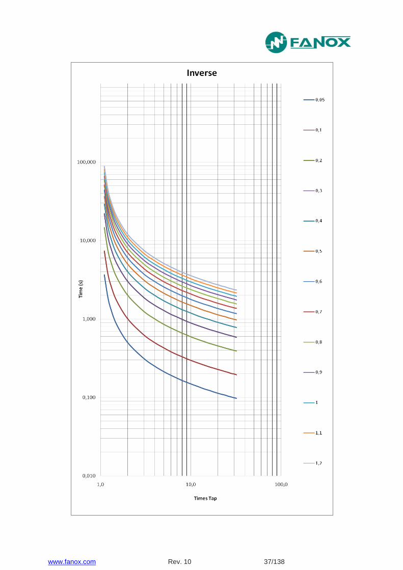
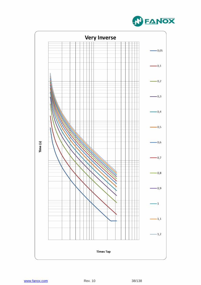
4.14. IEC 60255-151 Curves
The SIA-F relay complies with the curves shown in standard IEC 60255-151 Curves:
Inverse Curve
Very Inverse Curve
Extremely Inverse Curve
There is a general mathematical equation that defines the time in seconds as a function of the current:
Parameters A P Q B K
Ext. Inverse 80 2 1 0 0
Very Inverse 13,5 1 1 0 0
Inverse 0,14 0,02 1 0 0
The curve can be displaced on the axis using the time dial, D, which can be adjusted by the user. V is Times Tap
Iadjusted is the initial operating current, set by the user.
adjustedI
IV KDB
QV
DAt
P
www.fanox.com Rev. 10 40/138
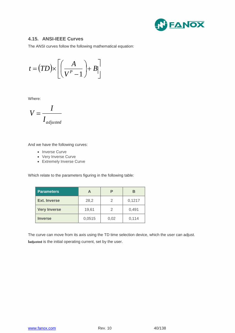
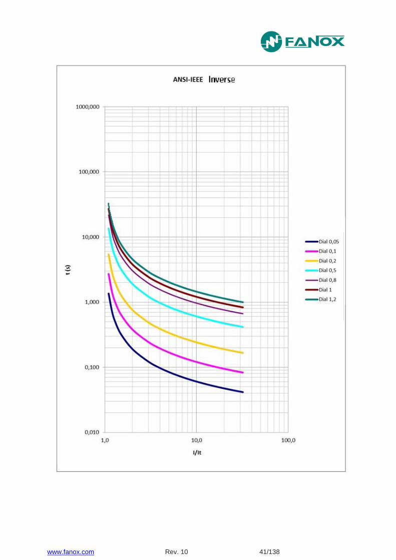
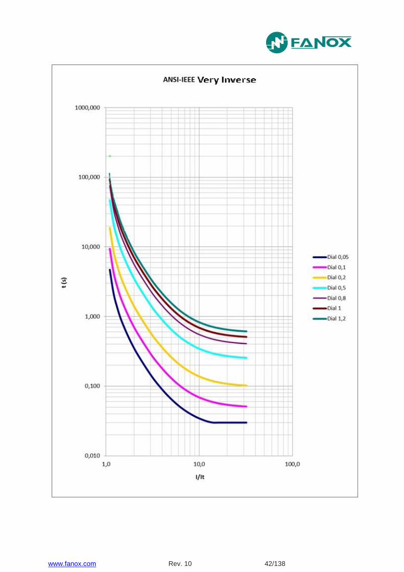
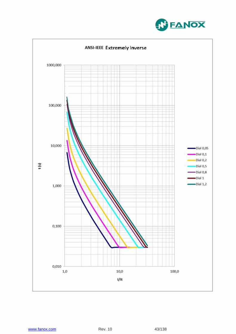
4.15. ANSI-IEEE Curves
The ANSI curves follow the following mathematical equation:
B
V
ATDt
P 1
Where:
adjustedI
IV
And we have the following curves:
Inverse Curve
Very Inverse Curve
Extremely Inverse Curve
Which relate to the parameters figuring in the following table:
Parameters A P B
Ext. Inverse 28,2 2 0,1217
Very Inverse 19,61 2 0,491
Inverse 0,0515 0,02 0,114
The curve can move from its axis using the TD time selection device, which the user can adjust.
Iadjusted is the initial operating current, set by the user.
www.fanox.com Rev. 10 44/138
4.16. Application examples
It is important to know that if both functions (50 and 50/51), phase or neutral, are enable, definite time function (function 50) must be more restrictive. So, if overcurrent fault values are low, inverse time overcurrent function (function 50/51) must work, and if overcurrent fault reaches a certain value, definite time overcurrent function will always work. This is because, when overcurrent fault reach high values (I>>), it is necessary to be sure that trip is going to be instantaneous to get that the element we are protecting, does not be damaged.
It is shown some examples below:
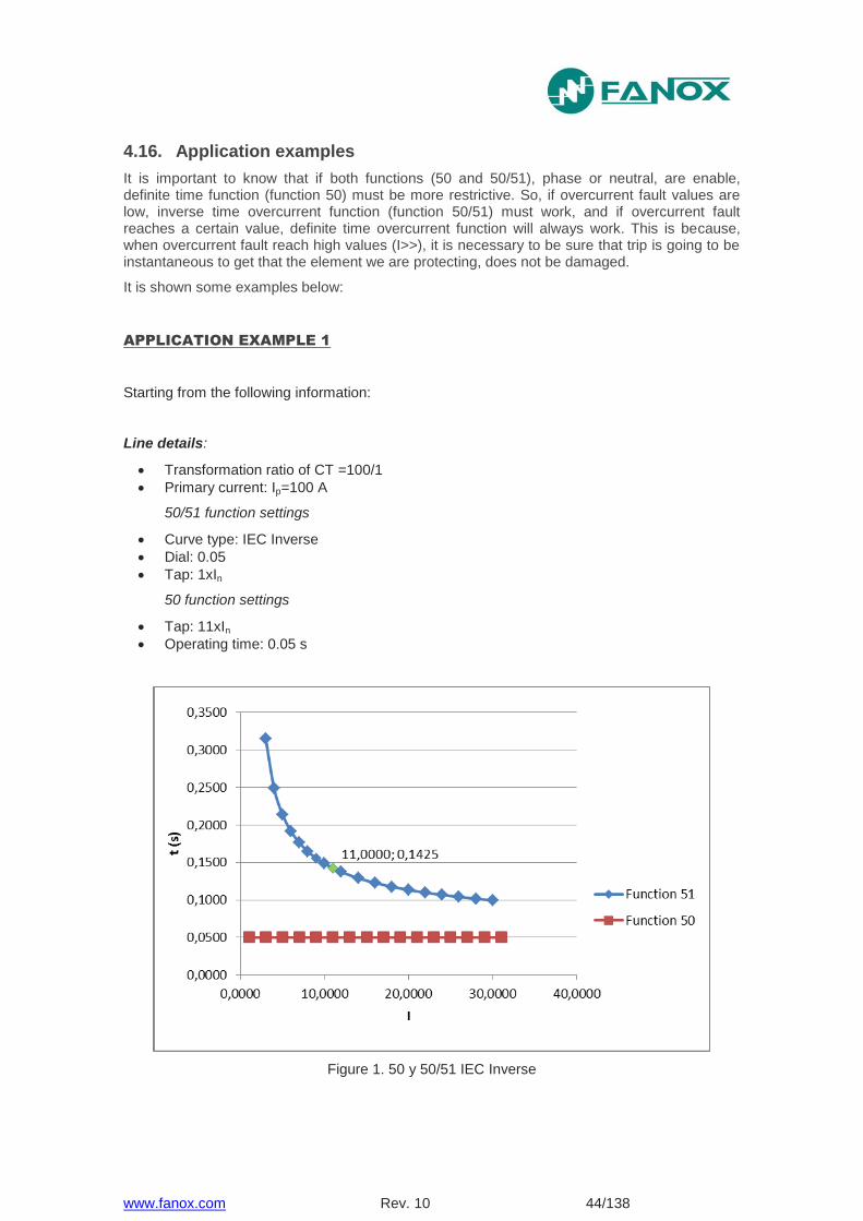
APPLICATION EXAMPLE 1
Starting from the following information:
Line details:
Transformation ratio of CT =100/1
Primary current: Ip=100 A
50/51 function settings
Curve type: IEC Inverse
Dial: 0.05
Tap: 1xIn
50 function settings
Tap: 11xIn
Operating time: 0.05 s
Figure 1. 50 y 50/51 IEC Inverse
www.fanox.com Rev. 10 45/138
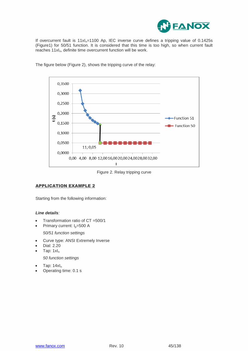
If overcurrent fault is 11xIn=1100 Ap, IEC inverse curve defines a tripping value of 0.1425s (Figure1) for 50/51 function. It is considered that this time is too high, so when current fault reaches 11xIn, definite time overcurrent function will be work.
The figure below (Figure 2), shows the tripping curve of the relay:
Figure 2. Relay tripping curve
APPLICATION EXAMPLE 2
Starting from the following information:
Line details:
Transformation ratio of CT =500/1
Primary current: Ip=500 A
50/51 function settings
Curve type: ANSI Extremely Inverse
Dial: 2.20
Tap: 1xIn
50 function settings
Tap: 14xIn
Operating time: 0.1 s

www.fanox.com Rev. 10 46/138
Figure 3. 50 y 50/51 ANSI Extremely Inverse
If overcurrent fault is 24xIn=12000 Ap, ANSI Extremely inverse curve defines a tripping value of 0.376 s (Figure 3) for 50/51 function. It is considered that this time is too high, so when current fault reaches 24xIn, definite time overcurrent function will be work. 50 function tap is adjusted at 14xIn so definite time overcurrent function will trip when current fault is higher than 14xIn (50 function does not wait to reach 24xIn) The figure below (Figure 4), shows the tripping curve of the relay:
Figure 4. Relay tripping curve
www.fanox.com Rev. 10 47/138
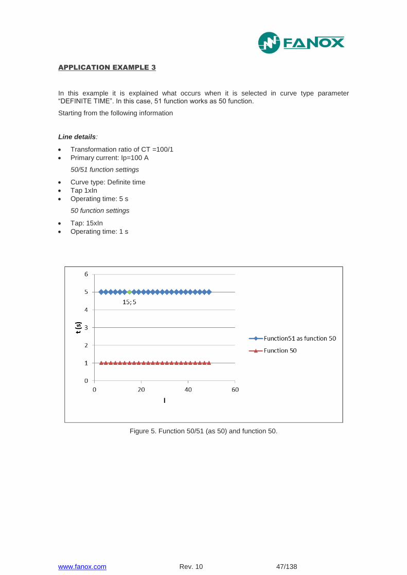
APPLICATION EXAMPLE 3
In this example it is explained what occurs when it is selected in curve type parameter “DEFINITE TIME”. In this case, 51 function works as 50 function.
Starting from the following information
Line details:
Transformation ratio of CT =100/1
Primary current: Ip=100 A
50/51 function settings
Curve type: Definite time
Tap 1xIn
Operating time: 5 s
50 function settings
Tap: 15xIn
Operating time: 1 s
Figure 5. Function 50/51 (as 50) and function 50.
www.fanox.com Rev. 10 48/138
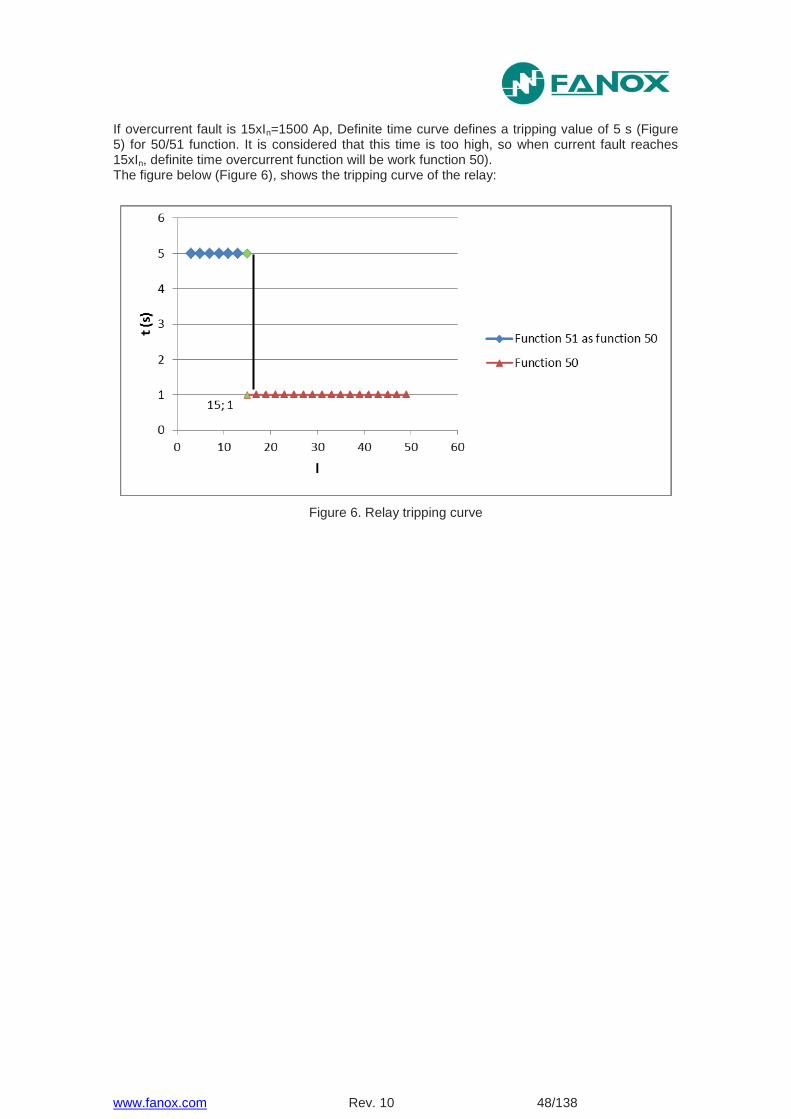
If overcurrent fault is 15xIn=1500 Ap, Definite time curve defines a tripping value of 5 s (Figure 5) for 50/51 function. It is considered that this time is too high, so when current fault reaches 15xIn, definite time overcurrent function will be work function 50). The figure below (Figure 6), shows the tripping curve of the relay:
Figure 6. Relay tripping curve
www.fanox.com Rev. 10 49/138
5. MONITORING AND CONTROL
5.1. Measurements
Measurements of the thermal image, three-phase currents, neutral current and maximum current are given in RMS. A sampling, of 16 samples/cycle, is performed.
The accuracy of the measurement is ±2% over a band of ±20% of rated current and ±4% over the rest of the measurement range.
Below are the phase and neutral measurement ranges of the SIAF models. There values are understood as secondary current:
Model Phase range Neutral range
Phase rated current
Neutral rated current
SIAF5* 1-150 A * 5 A *
SIAF1* 0,2-30 A * 1 A *
SIAF*5 * 1-150 A * 5 A
SIAF*1 * 0,2-30 A * 1 A
SIAF*B * 0,04-6 A * 0,2 A
Frequency 50 Hz or 60 Hz rated. ± 3 Hz
Thermal resistance 4 times rated current continuously.
20 times rated current for 10 s.
80 times rated current for 1s.
5.2. Counters
The SIA-F stores in non-volatile RAM memory:
Breaker opening number
Accumulated amperes during the breaker opening
www.fanox.com Rev. 10 50/138
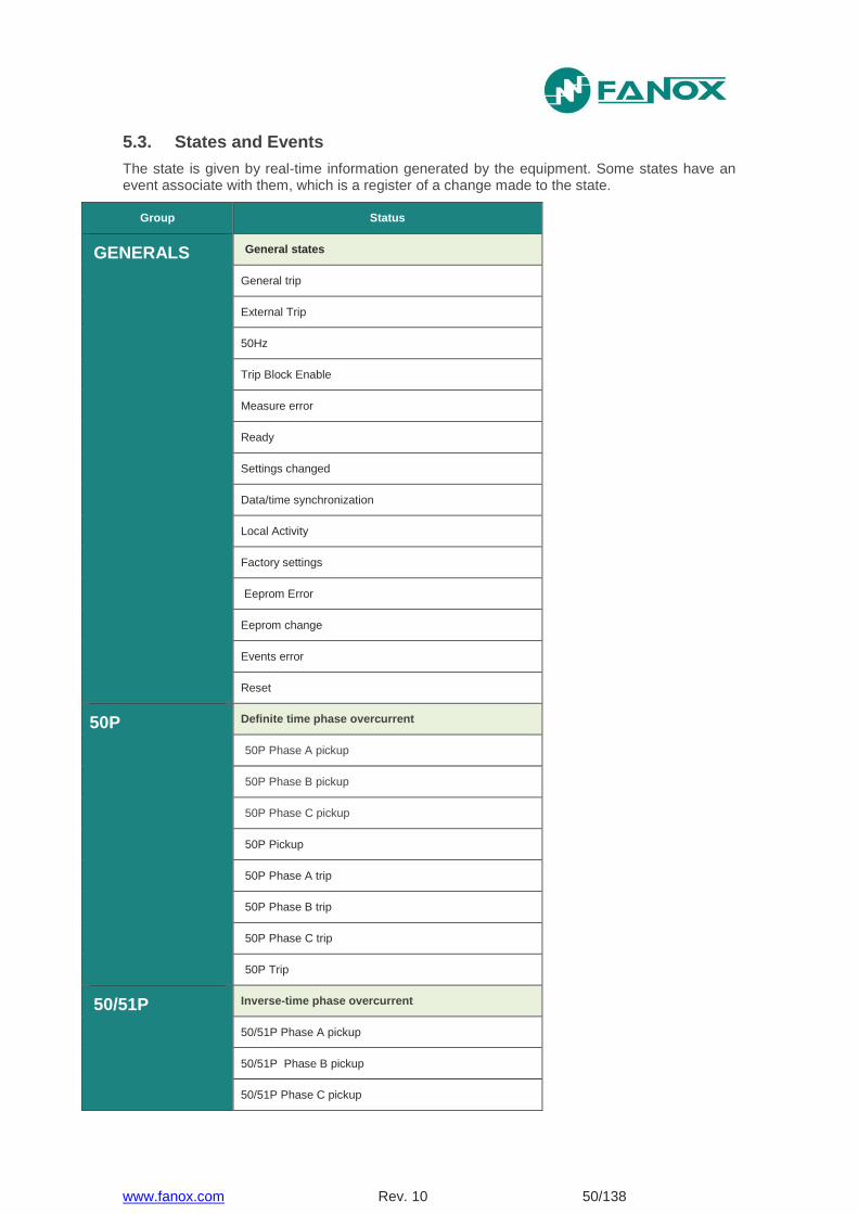
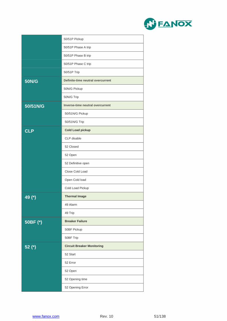
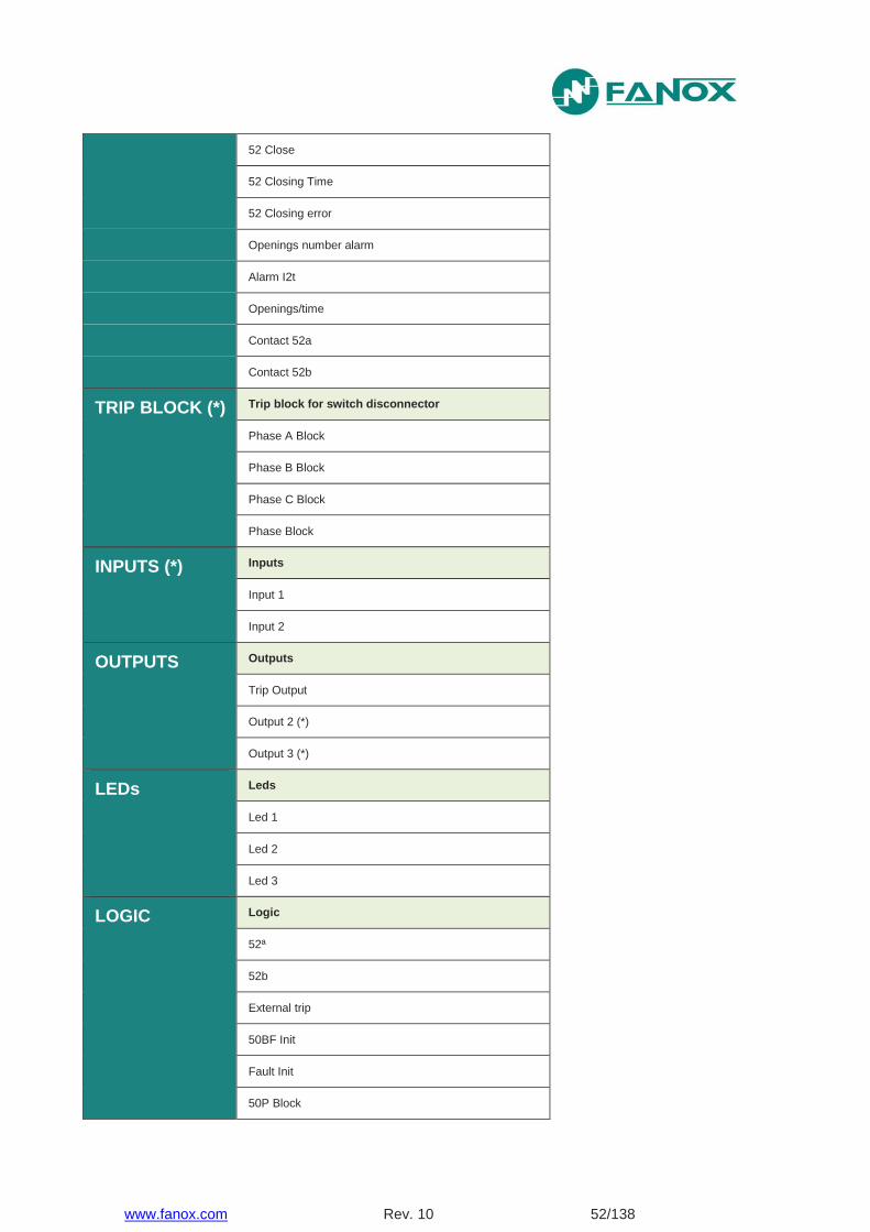
5.3. States and Events
The state is given by real-time information generated by the equipment. Some states have an event associate with them, which is a register of a change made to the state.
Group Status
GENERALS General states
General trip
External Trip
50Hz
Trip Block Enable
Measure error
Ready
Settings changed
Data/time synchronization
Local Activity
Factory settings
Eeprom Error
Eeprom change
Events error
Reset
50P Definite time phase overcurrent
50P Phase A pickup
50P Phase B pickup
50P Phase C pickup
50P Pickup
50P Phase A trip
50P Phase B trip
50P Phase C trip
50P Trip
50/51P Inverse-time phase overcurrent
50/51P Phase A pickup
50/51P Phase B pickup
50/51P Phase C pickup
www.fanox.com Rev. 10 51/138
50/51P Pickup
50/51P Phase A trip
50/51P Phase B trip
50/51P Phase C trip
50/51P Trip
50N/G Definite-time neutral overcurrent
50N/G Pickup
50N/G Trip
50/51N/G Inverse-time neutral overcurrent
50/51N/G Pickup
50/51N/G Trip
CLP Cold Load pickup
CLP disable
52 Closed
52 Open
52 Definitive open
Close Cold Load
Open Cold load
Cold Load Pickup
49 (*) Thermal Image
49 Alarm
49 Trip
50BF (*) Breaker Failure
50BF Pickup
50BF Trip
52 (*) Circuit Breaker Monitoring
52 Start
52 Error
52 Open
52 Opening time
52 Opening Error
www.fanox.com Rev. 10 52/138
52 Close
52 Closing Time
52 Closing error
Openings number alarm
Alarm I2t
Openings/time
Contact 52a
Contact 52b
TRIP BLOCK (*) Trip block for switch disconnector
Phase A Block
Phase B Block
Phase C Block
Phase Block
INPUTS (*) Inputs
Input 1
Input 2
OUTPUTS Outputs
Trip Output
Output 2 (*)
Output 3 (*)
LEDs Leds
Led 1
Led 2
Led 3
LOGIC Logic
52ª
52b
External trip
50BF Init
Fault Init
50P Block
www.fanox.com Rev. 10 53/138
50N/G Block
Reset
Settings Group 1
Settings Group 2
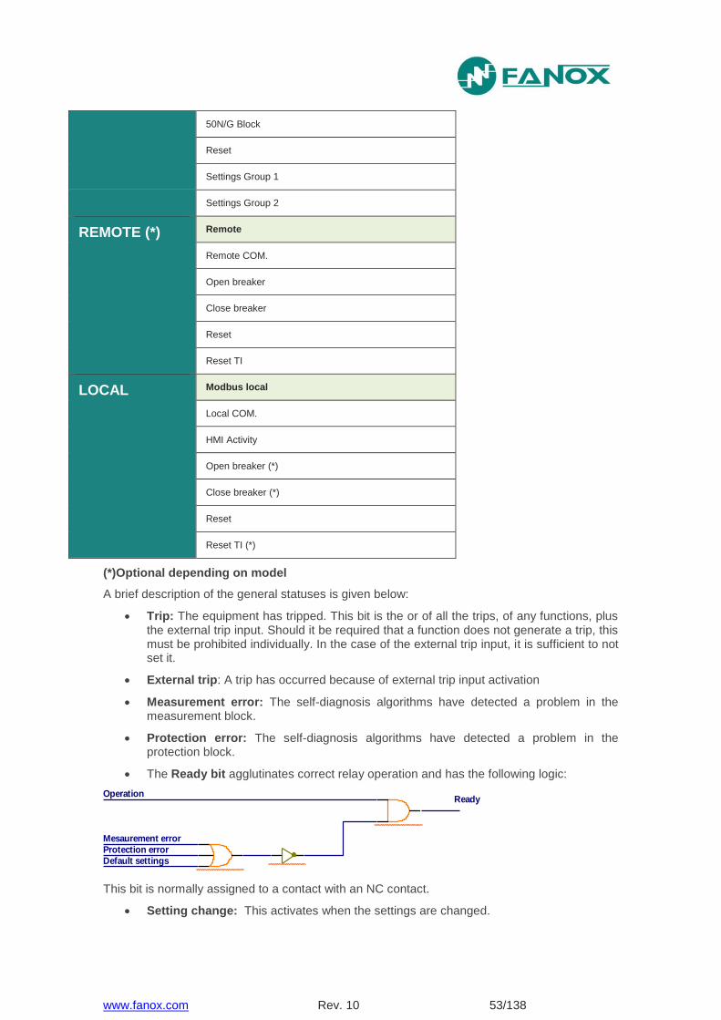
REMOTE (*)
Remote
Remote COM.
Open breaker
Close breaker
Reset
Reset TI
LOCAL Modbus local
Local COM.
HMI Activity
Open breaker (*)
Close breaker (*)
Reset
Reset TI (*)
(*)Optional depending on model
A brief description of the general statuses is given below:
Trip: The equipment has tripped. This bit is the or of all the trips, of any functions, plus the external trip input. Should it be required that a function does not generate a trip, this must be prohibited individually. In the case of the external trip input, it is sufficient to not set it.
External trip: A trip has occurred because of external trip input activation
Measurement error: The self-diagnosis algorithms have detected a problem in the measurement block.
Protection error: The self-diagnosis algorithms have detected a problem in the protection block.
The Ready bit agglutinates correct relay operation and has the following logic:
This bit is normally assigned to a contact with an NC contact.
Setting change: This activates when the settings are changed.
Operation
Mesaurement error
Protection errorDefault settings
Ready
www.fanox.com Rev. 10 54/138
Date-time setting: This activates when the date-time are synchronized.
Factory settings: the equipment is set to default settings and does not execute the trip.
Eeprom Error: The self-diagnosis algorithms have detected a problem in the eeprom memory, which contains the settings.
Eeprom change: this activates when the settings or configuration are changed. The settings change which this indication includes are differentiated from the configuration change, which are also stored in said memory.
Events error: The self-diagnosis algorithms have detected a corrupt event in the circular buffer. This bit is reset by deleting the events (from the HMI or by using communications).
HMI Activity: this condition is active if any key has been pressed in the last 15 minutes. Pressing a key implies that the relay is in local.
Local communication: this state is activated when communication through USB port is detected.
Some states have an event associate with them, which is a register of a change made to the state. There are states that have an activation event associated with them, and other states have two associated events: activation and reset. These events are registered in a circular memory (buffer) with a capacity for up to 200 events. The memory timestamp is accurate to 1 millisecond.
There are states that have an activation event associated with them, and other states have two associated events: activation and reset. These events are registered in a circular memory (buffer) with a capacity for up to 200 events. The memory timestamp is accurate to 1 millisecond.
The events will be registered in non-volatile RAM memory, and the events are conserved even if the equipment is not powered. If the Real Time Clock is used, the relay keeps and processes the correct date and time, even without electrical power, for up to 72 hours.
The events can be browsed from the HMI or by using communications. Reading the events does not mean that they get deleted; they remain stored on the equipment. To delete the events using the HMI, you have to go to the events menu and press and hold the "RESET" key until the number of events reads 1, and this event is registered as "Events deleted". To delete the events using communications, use the corresponding "delete events" command. To delete the events it is necessary to enter a password.
Events have the following structure:
Identify Unique event identifier: e.g.: 51_1.4 = 51P START
Value ON(Activated) /OFF(Deactivated): an event is generated for activations and deactivations
Year
Month
Day
Time
Minutes
Seconds
Milliseconds
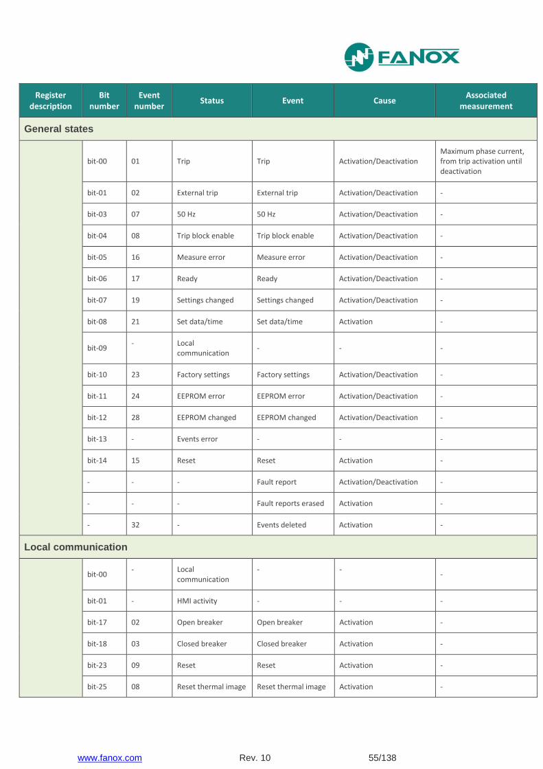
The following list shows all of the states of the equipment and their associated events:
www.fanox.com Rev. 10 55/138
Register description
Bit number
Event number
Status Event Cause Associated
measurement
General states
bit-00 01 Trip Trip Activation/Deactivation Maximum phase current, from trip activation until deactivation
bit-01 02 External trip External trip Activation/Deactivation -
bit-03 07 50 Hz 50 Hz Activation/Deactivation -
bit-04 08 Trip block enable Trip block enable Activation/Deactivation -
bit-05 16 Measure error Measure error Activation/Deactivation -
bit-06 17 Ready Ready Activation/Deactivation -
bit-07 19 Settings changed Settings changed Activation/Deactivation -
bit-08 21 Set data/time Set data/time Activation -
bit-09 - Local
communication - - -
bit-10 23 Factory settings Factory settings Activation/Deactivation -
bit-11 24 EEPROM error EEPROM error Activation/Deactivation -
bit-12 28 EEPROM changed EEPROM changed Activation/Deactivation -
bit-13 - Events error - - -
bit-14 15 Reset Reset Activation -
- - - Fault report Activation/Deactivation -
- - - Fault reports erased Activation -
- 32 - Events deleted Activation -
Local communication
bit-00 - Local
communication - -
-
bit-01 - HMI activity - - -
bit-17 02 Open breaker Open breaker Activation -
bit-18 03 Closed breaker Closed breaker Activation -
bit-23 09 Reset Reset Activation -
bit-25 08 Reset thermal image Reset thermal image Activation -
www.fanox.com Rev. 10 56/138
Register description
Bit number
Event number
Status Event Cause Associated
measurement
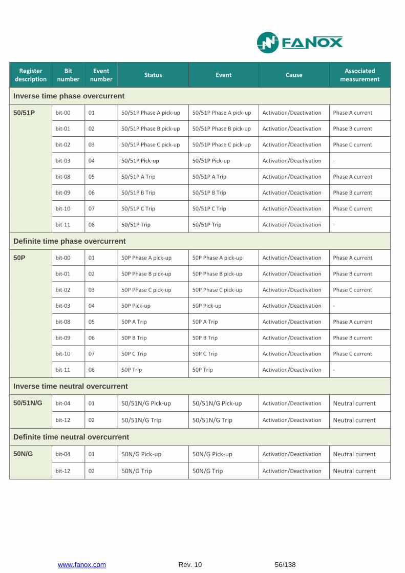
Inverse time phase overcurrent
50/51P bit-00 01 50/51P Phase A pick-up 50/51P Phase A pick-up Activation/Deactivation Phase A current
bit-01 02 50/51P Phase B pick-up 50/51P Phase B pick-up Activation/Deactivation Phase B current
bit-02 03 50/51P Phase C pick-up 50/51P Phase C pick-up Activation/Deactivation Phase C current
bit-03 04 50/51P Pick-up 50/51P Pick-up Activation/Deactivation -
bit-08 05 50/51P A Trip 50/51P A Trip Activation/Deactivation Phase A current
bit-09 06 50/51P B Trip 50/51P B Trip Activation/Deactivation Phase B current
bit-10 07 50/51P C Trip 50/51P C Trip Activation/Deactivation Phase C current
bit-11 08 50/51P Trip 50/51P Trip Activation/Deactivation -
Definite time phase overcurrent
50P bit-00 01 50P Phase A pick-up 50P Phase A pick-up Activation/Deactivation Phase A current
bit-01 02 50P Phase B pick-up 50P Phase B pick-up Activation/Deactivation Phase B current
bit-02 03 50P Phase C pick-up 50P Phase C pick-up Activation/Deactivation Phase C current
bit-03 04 50P Pick-up 50P Pick-up Activation/Deactivation -
bit-08 05 50P A Trip 50P A Trip Activation/Deactivation Phase A current
bit-09 06 50P B Trip 50P B Trip Activation/Deactivation Phase B current
bit-10 07 50P C Trip 50P C Trip Activation/Deactivation Phase C current
bit-11 08 50P Trip 50P Trip Activation/Deactivation -
Inverse time neutral overcurrent
50/51N/G bit-04 01 50/51N/G Pick-up 50/51N/G Pick-up Activation/Deactivation Neutral current
bit-12 02 50/51N/G Trip 50/51N/G Trip Activation/Deactivation Neutral current
Definite time neutral overcurrent
50N/G bit-04 01 50N/G Pick-up 50N/G Pick-up Activation/Deactivation Neutral current
bit-12 02 50N/G Trip 50N/G Trip Activation/Deactivation Neutral current

www.fanox.com Rev. 10 57/138
Register description
Bit numbe
r
Event number Status Event Cause
Associated measurement
Cold Load Pickup
CLP
- - CLP Disable - - -
- - 52 Closed - - -
- - 52 Open - - -
- - 52 Definitive open - - -
- - Close Cold Load - - -
- - Open Cold load - - -
bit-12 02 Cold Load Pickup Cold Load Pickup Activation/Deactivation -
Inputs
bit-00 17 Input 1 Input 1 Activation/Deactivation -
bit-01 18 Input 2 Input 2 Activation/Deactivation -
Outputs
bit-03 01 Trip Output Trip Output Activation/Deactivation -
bit-04 02 Output 2 Output 2 Activation/Deactivation -
bit-05 03 Output 3 Output 3 Activation/Deactivation -
Leds
bit-00 - LED 1 - - -
bit-01 - LED 2 - - -
bit-02 - LED 3 - - -

www.fanox.com Rev. 10 58/138
Register description
Bit numb
er
Event number Status Event Cause
Associated measurement
Logic
bit-06 18 52a 52a Activation/Deactivation -
bit-07 19 52b 52b Activation/Deactivation -
bit-08 22 External trip External trip Activation/Deactivation -
bit-09 07 50BF start 50BF start Activation/Deactivation -
bit-10 08 Fault start Fault start Activation/Deactivation -
bit-11 20 50P block 50P block Activation/Deactivation -
bit-12 21 50N/G block 50N/G block Activation/Deactivation -
bit-13 23 Reset Reset Activation/Deactivation
bit-14 24 Active group 1 Active group 1 Activation/Deactivation
bit-15 25 Active group 2 Active group 2 Activation/Deactivation
Trip block protection for the switchgear
bit-00 01 Phase A block Phase A block Activation/Deactivation Phase A current
bit-01 02 Phase B block Phase B block Activation/Deactivation Phase B current
bit-02 03 Phase C block Phase C block Activation/Deactivation Phase C current
bit-03 04 Phase block Phase block Activation/Deactivation -
Thermal image
49
bit-04 01 49 Alarm 49 Alarm Activation/Deactivation Thermal image value
bit-12 02 49 Trip 49 Trip Activation/Deactivation Thermal image value
Breaker failure
50BF
bit-00 01 50BF Pick-up 50BF Pick-up Activation/Deactivation -
bit-01 02 50BF Trip 50BF Trip Activation/Deactivation -
www.fanox.com Rev. 10 59/138
Register description
Bit numbe
r
Event number Status Event Cause
Associated measurement
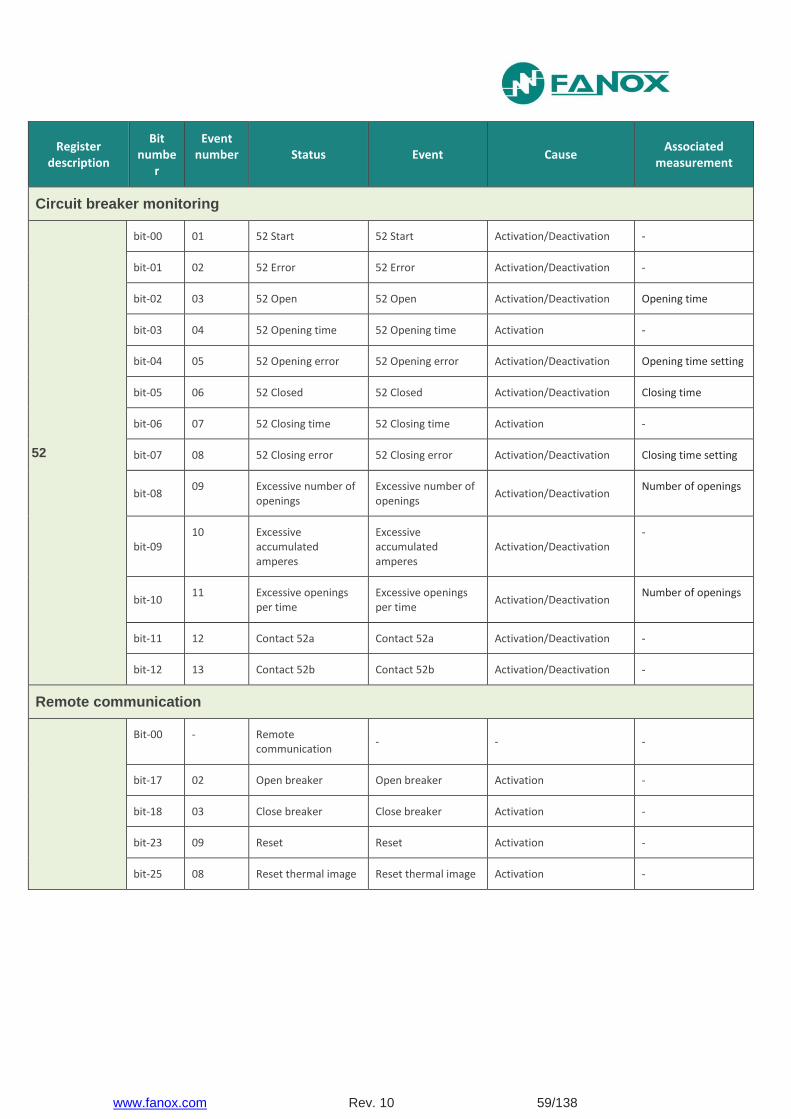
Circuit breaker monitoring
52
bit-00 01 52 Start 52 Start Activation/Deactivation -
bit-01 02 52 Error 52 Error Activation/Deactivation -
bit-02 03 52 Open 52 Open Activation/Deactivation Opening time
bit-03 04 52 Opening time 52 Opening time Activation -
bit-04 05 52 Opening error 52 Opening error Activation/Deactivation Opening time setting
bit-05 06 52 Closed 52 Closed Activation/Deactivation Closing time
bit-06 07 52 Closing time 52 Closing time Activation -
bit-07 08 52 Closing error 52 Closing error Activation/Deactivation Closing time setting
bit-08 09 Excessive number of
openings Excessive number of openings
Activation/Deactivation Number of openings
bit-09 10 Excessive
accumulated amperes
Excessive accumulated amperes
Activation/Deactivation -
bit-10 11 Excessive openings
per time Excessive openings per time
Activation/Deactivation Number of openings
bit-11 12 Contact 52a Contact 52a Activation/Deactivation -
bit-12 13 Contact 52b Contact 52b Activation/Deactivation -
Remote communication
Bit-00 - Remote communication
- - -
bit-17 02 Open breaker Open breaker Activation -
bit-18 03 Close breaker Close breaker Activation -
bit-23 09 Reset Reset Activation -
bit-25 08 Reset thermal image Reset thermal image Activation -
www.fanox.com Rev. 10 60/138
5.4. Fault Reports
A fault report is a record of specific events in the period of time when a fault occurs. Event recording can be filled with general events, which provide no information of a fault (settings change, local pulsing, etc.) whereby it could be filled with general information, losing any fault information. Therefore, having a specific events record for the fault period is of significant help to resolve an incident.
This record has a 4 fault capacity, and each fault can store 16 events. At any moment, the information of the twenty most recent fault reports is available. Each new fault report generated is stored on the oldest, is lost, therefore, the information of this one. The fault report is time limited by means of a fault start and a fault end, and these must be clearly established.
The fault report´s start is configurable. When all start-ups disappear it is understood that the fault has disappeared.
The four fault reports are registered in non-volatile RAM memory. From the standby mode screen, press the “OK” key to access the first line of menus. Use the “▲” and “▼” keys to position the cursor over the “FAULT REPORTS” screen. The next information can be checked:
Date-time at which the fault started.
List of all events occurred in the equipment during the fault.
Tap of the protection function that causes the fault report
To delete the fault reports buffer, position the cursor over the fault report menu and press and hold the "RESET" key, until there is no fault reports. There will be an event "Fault reports erased".
5.5. Date and Time by Real Time Clock (RTC)
The Protection devices require a clock, enabling them to have a date and time stamped for events and registers. This clock has a capacitor that allows operation while maintaining the date and time even without power, up to 72 hours (It is understood that the capacitor was previously loaded).
If an event queue occurs, and if synchronized with a date-time previous to the last stored event, the relay will not rearrange the queue but will store the new events immediately after the stored events.
This clock can be synchronized by any of the two following procedures:
From the HMI. In this case the date and time can be entered via the keyboard. The relay will store the new event indicating that it has been synchronized.
Protocol. The behavior is identical to the HMI. The relay will synchronize the date and time, and a new synchronization event is carried out.
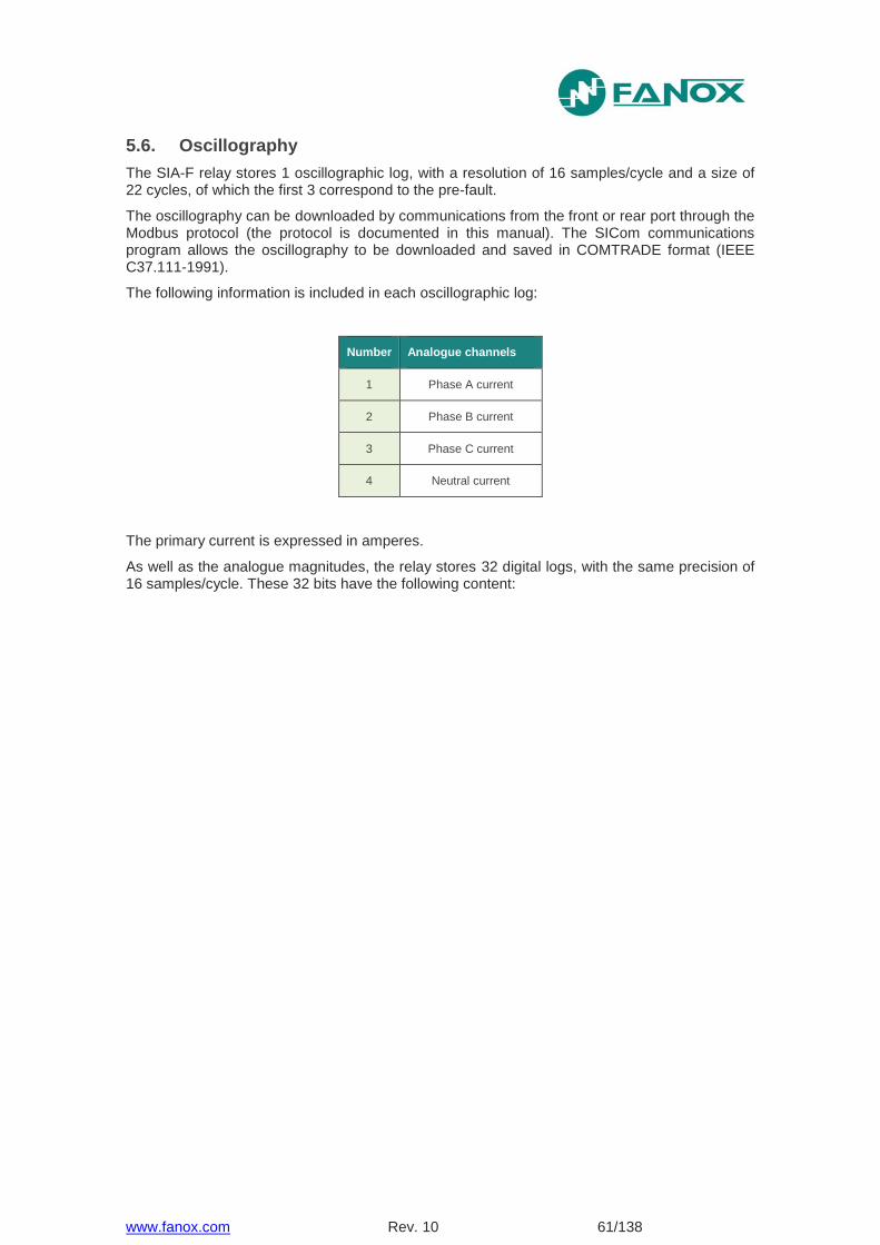
www.fanox.com Rev. 10 61/138
5.6. Oscillography
The SIA-F relay stores 1 oscillographic log, with a resolution of 16 samples/cycle and a size of 22 cycles, of which the first 3 correspond to the pre-fault.
The oscillography can be downloaded by communications from the front or rear port through the Modbus protocol (the protocol is documented in this manual). The SICom communications program allows the oscillography to be downloaded and saved in COMTRADE format (IEEE C37.111-1991).
The following information is included in each oscillographic log:
Number Analogue channels
1 Phase A current
2 Phase B current
3 Phase C current
4 Neutral current
The primary current is expressed in amperes.
As well as the analogue magnitudes, the relay stores 32 digital logs, with the same precision of 16 samples/cycle. These 32 bits have the following content:
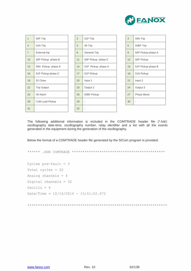
www.fanox.com Rev. 10 62/138
1 50P Trip 2 51P Trip 3 50N Trip
4 51N Trip 5 49 Trip 6 50BF Trip
7 External trip 8 General Trip 9 50P Pickup phase A
10 50P Pickup phase B 11 50P Pickup phase C 12 50P Pickup
13 50N Pickup phase A 14 51P Pickup phase A 15 51P Pickup phase B
16 51P Pickup phase C 17 51P Pickup 18 51N Pickup
19 52 Close 20 Input 1 21 Input 2
22 Trip Output 23 Output 2 24 Output 3
25 49 Alarm 26 50BF Pickup 27 Phase Block
28 Cold Load Pickup 29 - 30 -
31 - 32 -
The following additional information is included in the COMTRADE header file (*.hdr): oscillography date-time, oscillography number, relay identifier and a list with all the events generated in the equipment during the generation of the oscillography.
Below the format of a COMTRADE header file generated by the SICom program is provided:
****** .HDR COMTRADE ********************************************
Cycles pre-fault = 3
Total cycles = 22
Analog channels = 4
Digital channels = 32
Oscillo = 4
Date/Time = 10/16/2014 - 15:51:52.472
******************************************************************
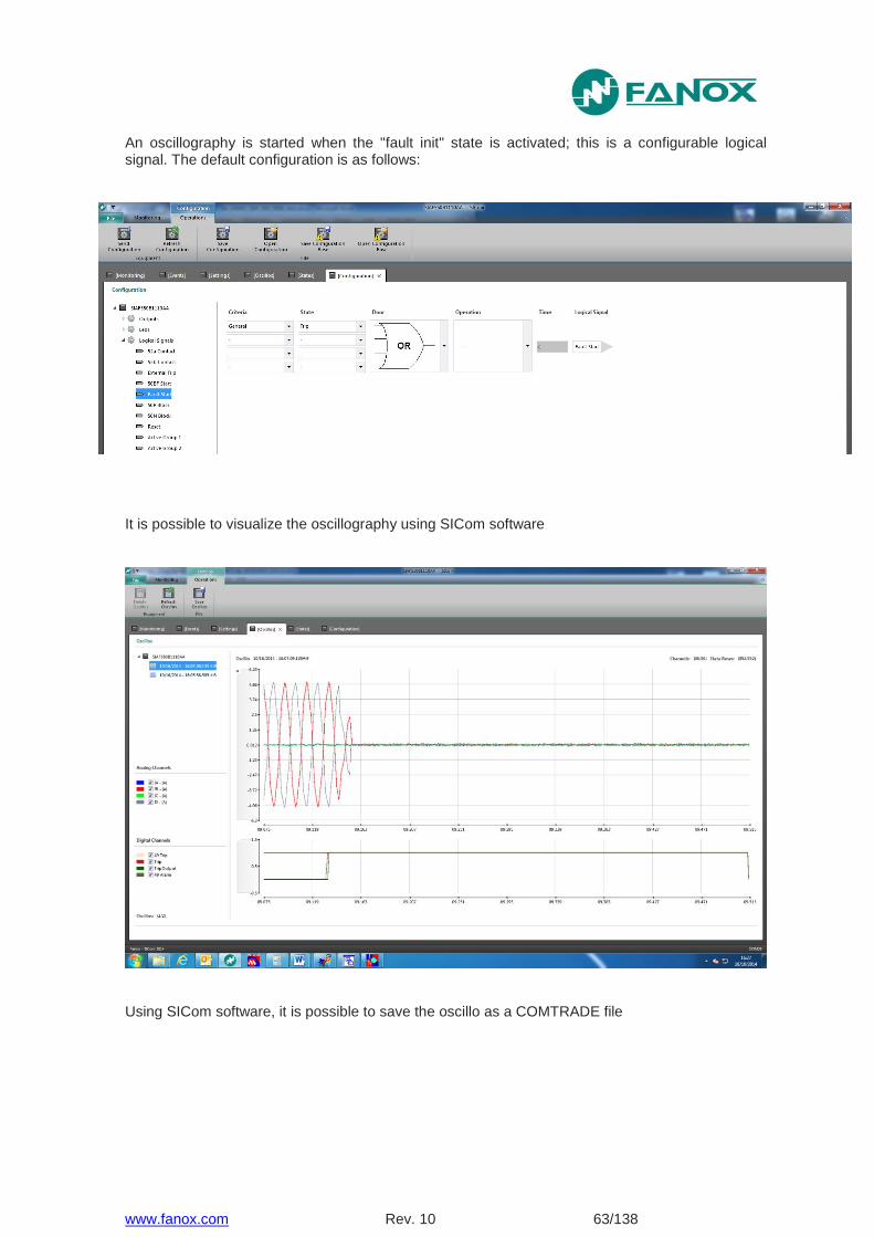
www.fanox.com Rev. 10 63/138
An oscillography is started when the "fault init" state is activated; this is a configurable logical signal. The default configuration is as follows:
It is possible to visualize the oscillography using SICom software
Using SICom software, it is possible to save the oscillo as a COMTRADE file
www.fanox.com Rev. 10 64/138
5.7. Digital Inputs
The SIA-F has two digital inputs that can be configured by the user.
The configuration of the inputs is described in point 5.9 Programmable Logic Control & Digital Outputs.
5.8. Configurable Outputs
The SIA-F has up to 3 physical outputs (trip output, output 2 and output 3). The outputs can be configured from the HMI or through the SICom program.
The configuration of the outputs is described in point 5.9 Programmable Logic Control & Digital Outputs
5.9. Programmable Logic Control & Digital Outputs
Firstly, it is defined the concept of physical input, physical output and logical signal.
Physical inputs are the real inputs of the device. SIA-F device has two physical inputs (Input 1 and Input 2). These inputs are translated to two internal binary states which later, can be assigned to logical signal to get a specific operation.
Physical outputs are the real outputs of the Device. SIA-F has a trip output and other two digital outputs (Output 2 and Output 3). SIA-F device has 3 LEDS (Led1, Led 2 and Led 3), which receive the same treatment as the physical outputs, some working on output relays and others working on led diodes.

www.fanox.com Rev. 10 65/138
Logical signals are internal binary states result of the Programmable Logic Control. The logical signal has a specific and defined meaning to be used by the rest functions of the Device.
LEDs
LED 1
LED 2
LED 3
PHYSICAL OUTPUTS
Trip Output
Output 2
Output 3
LOGICAL SIGNALS
52a contact logical signal
52b contact logical signal
External Trip logical signal
50BF start logical signal
Fault start logical signal
50P block logical signal
50N/G block logical signal
Reset logical signal
Active group 1 logical signal
Active group 2 logical signal
All the outputs (Leds, physical outputs and logical signals) are the result of a PROGRAMMABLE LOGIC CONTROL which can be configured from HMI or from SICom software.
For each output there is a LOGICAL GATE. It can perform a logical operation up to 4 binary states to obtain other binary result.
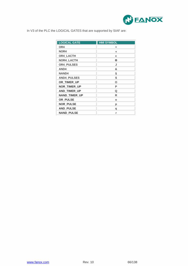
www.fanox.com Rev. 10 66/138
In V3 of the PLC the LOGICAL GATES that are supported by SIAF are:
LOGICAL GATE HMI SYMBOL
OR4 +
NOR4
OR4_LACTH c
NOR4_LACTH Φ
OR4_PULSES J
AND4 &
NAND4 §
AND4_PULSES $
OR_TIMER_UP O
NOR_TIMER_UP P
AND_TIMER_UP Q
NAND_TIMER_UP R
OR_PULSE o
NOR_PULSE p
AND_PULSE q
NAND_PULSE r
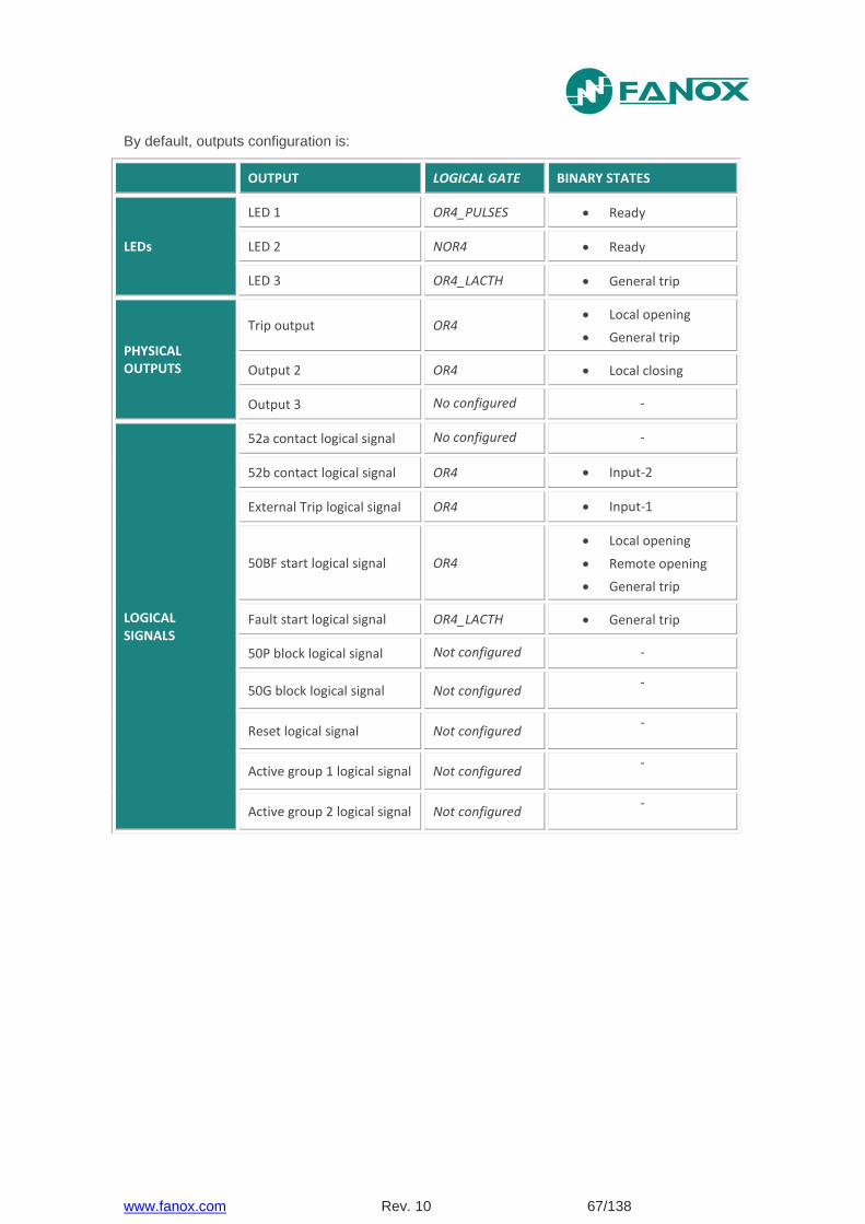
www.fanox.com Rev. 10 67/138
By default, outputs configuration is:
OUTPUT LOGICAL GATE BINARY STATES
LEDs
LED 1 OR4_PULSES Ready
LED 2 NOR4 Ready
LED 3 OR4_LACTH General trip
PHYSICAL OUTPUTS
Trip output OR4 Local opening
General trip
Output 2 OR4 Local closing
Output 3 No configured -
LOGICAL SIGNALS
52a contact logical signal No configured -
52b contact logical signal OR4 Input-2
External Trip logical signal OR4 Input-1
50BF start logical signal OR4
Local opening
Remote opening
General trip
Fault start logical signal OR4_LACTH General trip
50P block logical signal Not configured -
50G block logical signal Not configured -
Reset logical signal Not configured -
Active group 1 logical signal Not configured -
Active group 2 logical signal Not configured -

www.fanox.com Rev. 10 68/138
We are going to use configuration by default as an example:
OUTPUT LOGICAL GATE BINARY STATES DESCRIPTIONS
LED 1 OR4_PULSES Ready
Led On blinks when internal signal “READY” of general state of the device is activated, this indicates that the device is working correctly without any failures.
LED 2 NOR4 Ready
Led alarm will activate when internal signal “READY” of general state of the device is deactivated, this indicates some failure has occurred.
LED 3 OR4_LACTH General Trip
Led trip will activate when internal signal “GENERAL TRIP” of general state of the device is activated, this indicates that some protection function has tripped. This led will continue activated until the reset of the leds is made.
Trip output OR4 Local opening
General trip
Trip output will activate when there is a general trip or when 52 opening command is carried out, from local communications or from HMI.
Output 2 OR4 Local closing
Output 2 will be activated when 52 closing command is carried out from local communications or from HMI.
52b logical signal OR4 Input-2
When physical input 2 is activated, 52a logical output will be activated, and it will used to determine the breaker state.
External trip logical signal OR4 Input-1
When physical input 1 is activated external trip logical output will be activated, and it will be used to generate a general trip by general protection function.
Start 50BF logical signal OR4
Local opening
Remote opening
General trip
When a general trip has occurred or when 52a opening command is carried out from local communications start 50BF logical output will be activated and it will be used to initiate the detection of breaker failure by 50BF function.
Fault Start logical signal OR4_LACTH General trip
When general trip is activated, fault start logical output will be activated and it will generate a new fault register.
5.10. 86 Function. Trip Output Lockout
When the TRIP OUTPUT is configured like OR4_LACTH the programmable logic allows this output to block.
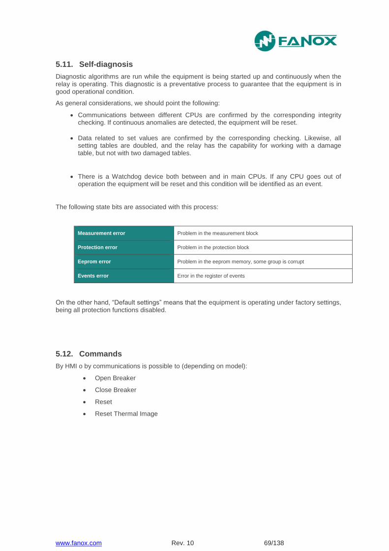
www.fanox.com Rev. 10 69/138
5.11. Self-diagnosis
Diagnostic algorithms are run while the equipment is being started up and continuously when the relay is operating. This diagnostic is a preventative process to guarantee that the equipment is in good operational condition.
As general considerations, we should point the following:
Communications between different CPUs are confirmed by the corresponding integrity checking. If continuous anomalies are detected, the equipment will be reset.
Data related to set values are confirmed by the corresponding checking. Likewise, all setting tables are doubled, and the relay has the capability for working with a damage table, but not with two damaged tables.
There is a Watchdog device both between and in main CPUs. If any CPU goes out of operation the equipment will be reset and this condition will be identified as an event.
The following state bits are associated with this process:
Measurement error Problem in the measurement block
Protection error Problem in the protection block
Eeprom error Problem in the eeprom memory, some group is corrupt
Events error Error in the register of events
On the other hand, “Default settings” means that the equipment is operating under factory settings, being all protection functions disabled.
5.12. Commands
By HMI o by communications is possible to (depending on model):
Open Breaker
Close Breaker
Reset
Reset Thermal Image
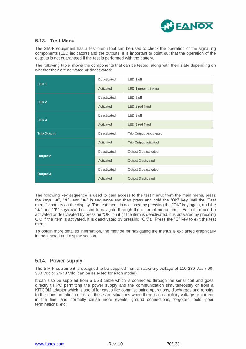
www.fanox.com Rev. 10 70/138
5.13. Test Menu
The SIA-F equipment has a test menu that can be used to check the operation of the signalling components (LED indicators) and the outputs. It is important to point out that the operation of the outputs is not guaranteed if the test is performed with the battery.
The following table shows the components that can be tested, along with their state depending on whether they are activated or deactivated:
LED 1
Deactivated LED 1 off
Activated LED 1 green blinking
LED 2
Deactivated LED 2 off
Activated LED 2 red fixed
LED 3
Deactivated LED 3 off
Activated LED 3 red fixed
Trip Output Deactivated Trip Output deactivated
Activated Trip Output activated
Output 2
Deactivated Output 2 deactivated
Activated Output 2 activated
Output 3
Deactivated Output 3 deactivated
Activated Output 3 activated
The following key sequence is used to gain access to the test menu: from the main menu, press the keys “◄”, “▼”, and “►” in sequence and then press and hold the "OK" key until the "Test menu" appears on the display. The test menu is accessed by pressing the "OK" key again, and the “▲” and “▼” keys can be used to navigate through the different menu items. Each item can be activated or deactivated by pressing "OK" on it (if the item is deactivated, it is activated by pressing OK; if the item is activated, it is deactivated by pressing “OK”). Press the “C” key to exit the test menu.
To obtain more detailed information, the method for navigating the menus is explained graphically in the keypad and display section.
5.14. Power supply
The SIA-F equipment is designed to be supplied from an auxiliary voltage of 110-230 Vac / 90-300 Vdc or 24-48 Vdc (can be selected for each model).
It can also be supplied from a USB cable which is connected through the serial port and goes directly till PC permitting the power supply and the communication simultaneously or from a KITCOM adaptor which is useful for cases like commissioning operations, discharges and repairs to the transformation center as these are situations when there is no auxiliary voltage or current in the line, and normally cause more events, ground connections, forgotten tools, poor terminations, etc.
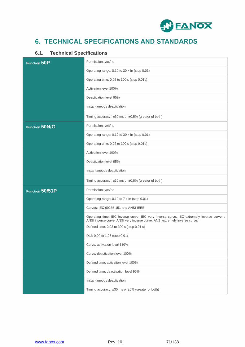
www.fanox.com Rev. 10 71/138
6. TECHNICAL SPECIFICATIONS AND STANDARDS
6.1. Technical Specifications
Function 50P Permission: yes/no
Operating range: 0.10 to 30 x In (step 0.01)
Operating time: 0.02 to 300 s (step 0.01s)
Activation level 100%
Deactivation level 95%
Instantaneous deactivation
Timing accuracy: ±30 ms or ±0,5% (greater of both)
Function 50N/G Permission: yes/no
Operating range: 0.10 to 30 x In (step 0.01)
Operating time: 0.02 to 300 s (step 0.01s)
Activation level 100%
Deactivation level 95%
Instantaneous deactivation
Timing accuracy: ±30 ms or ±0,5% (greater of both)
Function 50/51P Permission: yes/no
Operating range: 0.10 to 7 x In (step 0.01)
Curves: IEC 60255-151 and ANSI-IEEE
Operating time: IEC inverse curve, IEC very inverse curve, IEC extremely inverse curve, : ANSI inverse curve, ANSI very inverse curve, ANSI extremely inverse curve.
Defined time: 0.02 to 300 s (step 0.01 s)
Dial: 0.02 to 1.25 (step 0.01)
Curve, activation level 110%
Curve, deactivation level 100%
Defined time, activation level 100%
Defined time, deactivation level 95%
Instantaneous deactivation
Timing accuracy: ±30 ms or ±5% (greater of both)
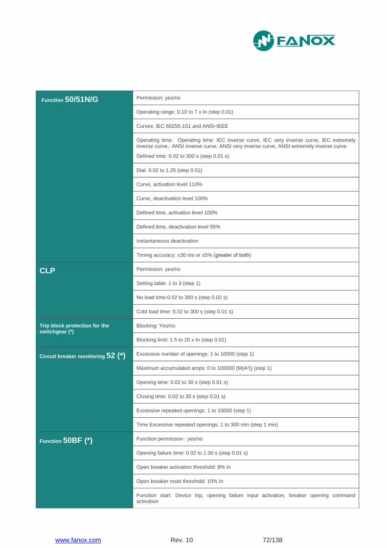
www.fanox.com Rev. 10 72/138
Function 50/51N/G Permission: yes/no
Operating range: 0.10 to 7 x In (step 0.01)
Curves: IEC 60255-151 and ANSI-IEEE
Operating time: Operating time: IEC inverse curve, IEC very inverse curve, IEC extremely inverse curve,: ANSI inverse curve, ANSI very inverse curve, ANSI extremely inverse curve.
Defined time: 0.02 to 300 s (step 0.01 s)
Dial: 0.02 to 1.25 (step 0.01)
Curve, activation level 110%
Curve, deactivation level 100%
Defined time, activation level 100%
Defined time, deactivation level 95%
Instantaneous deactivation
Timing accuracy: ±30 ms or ±5% (greater of both)
CLP Permission: yes/no
Setting table: 1 to 3 (step 1)
No load time:0.02 to 300 s (step 0.02 s)
Cold load time: 0.02 to 300 s (step 0.01 s)
Trip block protection for the switchgear (*)
Blocking: Yes/no
Blocking limit: 1.5 to 20 x In (step 0.01)
Circuit breaker monitoring 52 (*) Excessive number of openings: 1 to 10000 (step 1)
Maximum accumulated amps: 0 to 100000 (M(A²)) (step 1)
Opening time: 0.02 to 30 s (step 0.01 s)
Closing time: 0.02 to 30 s (step 0.01 s)
Excessive repeated openings: 1 to 10000 (step 1)
Time Excessive repeated openings: 1 to 300 min (step 1 min)
Function 50BF (*) Function permission : yes/no
Opening failure time: 0.02 to 1.00 s (step 0.01 s)
Open breaker activation threshold: 8% In
Open breaker reset threshold: 10% In
Function start: Device trip, opening failure input activation, breaker opening command activation

www.fanox.com Rev. 10 73/138
Function 49 (*)
Function permission : yes/no
Tap: 0.10 a 2.40 Inominal (step 0.01)
ζ heating: 3 a 600 minutes (step 1 min)
ζ cooling: 1 a 6 x ζ heating (step 1)
Alarm level: 20 a 99% (step 1 %)
Trip level: 100%
Trip reset: 95% of alarm level
Timing accuracy:± 5% or± 2 s (greater of both)
Function 68 (*) Available through configurable inputs thanks to programmable logic
Programmable logic control (PLC) OR4, NOR, OR4_LATCH, NOR4_LATCH, OR4_PULSES, AND4, NAND4, AND4_PULSES, OR4_TIMER, NOR4_TIMER4_UP, AND4_TIMER_UP, NAND4_TIMER_UP
Function 86 Allows to latch (lock out) the contact trip due to programmable logic (PLC).
Function 49T (*) Available through configurable inputs
Settings tables 3 settings tables
Activated by general settings or by inputs
RTC Capacitor charge time: 10 minutes
Operation without auxiliary voltage: 72 hours
Trip output (configurable) Potential free contact
2 configurable outputs (*) Resistive load:
250 Vac – 8 A
30 Vdc – 5 A
2 configurable inputs (*) The same voltage as auxiliary power supply
Frequency 50/60Hz
Current measure True RMS
Sampling: 16 samples/cycle
Accuracy of ±2% in a band of ±20% over the rated current and ±4% for the rest of measurement range
Saturation limit: 30 times rated current
Fault reports 4 fault reports with 16 events each
Oscillography 16 samples/cycle
Oscillo starting configuration
1 record: 3 cycles pre-fault and 19 post-fault

www.fanox.com Rev. 10 74/138
(*) Depending on model
6.2. Thermal resistance
4 times rated current continously.
20 times rated current for 10 s.
80 times rated current for 1s.
COMTRADE IEEE C37.111-1991
4 analogue channels and 32 digital channels
Communications USB port (connector mini USB type A): Modbus RTU
RS485 port: Modbus RTU (*)
Auxiliary power supply (*) 110-230 Vac / 90-300 Vdc ±20%
24-48 Vdc ±20%
Battery supply With KITCOM adapter to USB (connector USB type B)
Environment Operating temperature: -10 to +70ºC
Storage temperature: -20 to +80 ºC
Humidity: 95%
Transformers 3 or 4 CT /5, /1 or /0.2
Mechanical features Metallic box
Panel Mounting
1/4 Rack – 4 U
Depth: 74.6 mm
IP-54 on panel
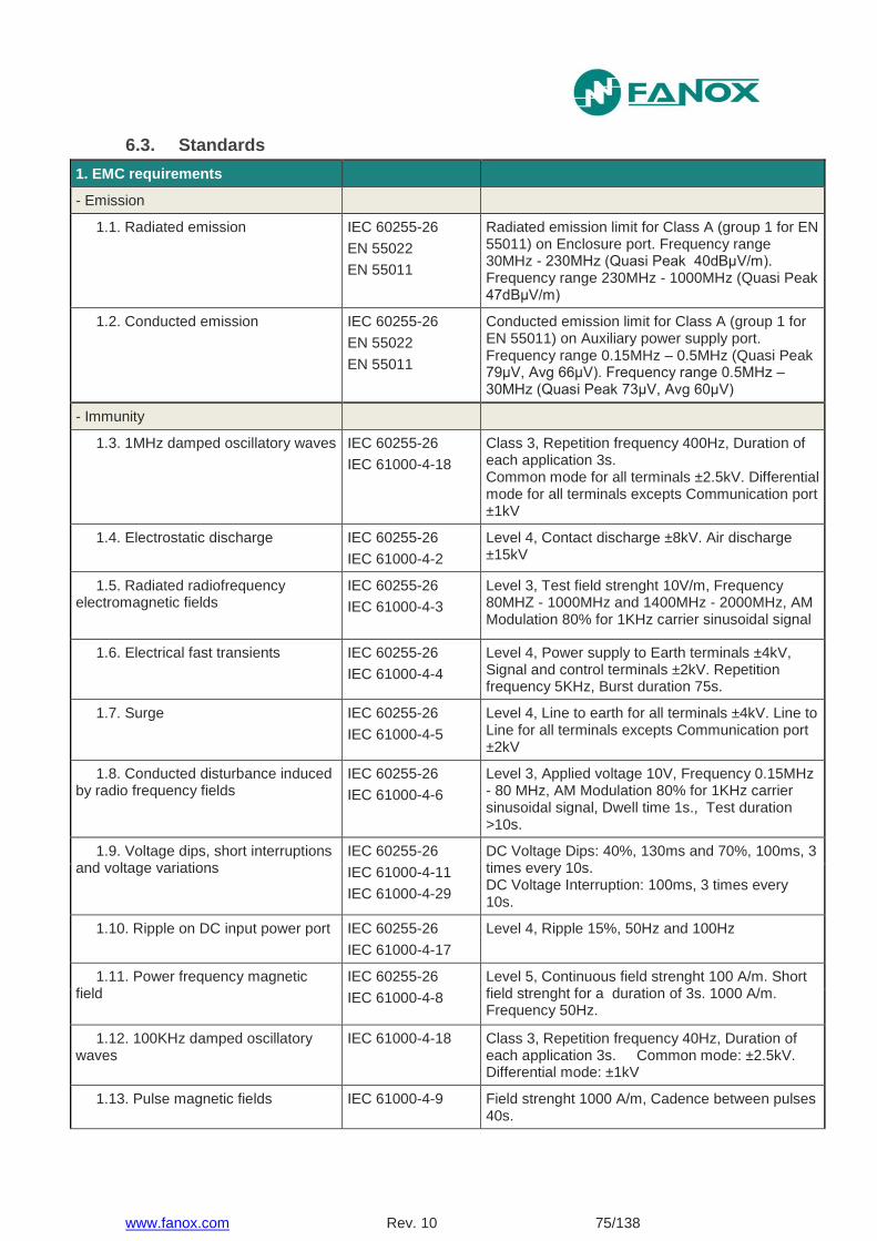
www.fanox.com Rev. 10 75/138
6.3. Standards
1. EMC requirements
- Emission
1.1. Radiated emission IEC 60255-26
EN 55022
EN 55011
Radiated emission limit for Class A (group 1 for EN 55011) on Enclosure port. Frequency range 30MHz - 230MHz (Quasi Peak 40dBμV/m). Frequency range 230MHz - 1000MHz (Quasi Peak 47dBμV/m)
1.2. Conducted emission IEC 60255-26
EN 55022
EN 55011
Conducted emission limit for Class A (group 1 for EN 55011) on Auxiliary power supply port. Frequency range 0.15MHz – 0.5MHz (Quasi Peak 79μV, Avg 66μV). Frequency range 0.5MHz – 30MHz (Quasi Peak 73μV, Avg 60μV)
- Immunity
1.3. 1MHz damped oscillatory waves IEC 60255-26
IEC 61000-4-18
Class 3, Repetition frequency 400Hz, Duration of each application 3s. Common mode for all terminals ±2.5kV. Differential mode for all terminals excepts Communication port ±1kV
1.4. Electrostatic discharge IEC 60255-26
IEC 61000-4-2
Level 4, Contact discharge ±8kV. Air discharge ±15kV
1.5. Radiated radiofrequency electromagnetic fields
IEC 60255-26
IEC 61000-4-3
Level 3, Test field strenght 10V/m, Frequency 80MHZ - 1000MHz and 1400MHz - 2000MHz, AM Modulation 80% for 1KHz carrier sinusoidal signal
1.6. Electrical fast transients IEC 60255-26
IEC 61000-4-4
Level 4, Power supply to Earth terminals ±4kV, Signal and control terminals ±2kV. Repetition frequency 5KHz, Burst duration 75s.
1.7. Surge IEC 60255-26
IEC 61000-4-5
Level 4, Line to earth for all terminals ±4kV. Line to Line for all terminals excepts Communication port ±2kV
1.8. Conducted disturbance induced by radio frequency fields
IEC 60255-26
IEC 61000-4-6
Level 3, Applied voltage 10V, Frequency 0.15MHz - 80 MHz, AM Modulation 80% for 1KHz carrier sinusoidal signal, Dwell time 1s., Test duration >10s.
1.9. Voltage dips, short interruptions and voltage variations
IEC 60255-26
IEC 61000-4-11
IEC 61000-4-29
DC Voltage Dips: 40%, 130ms and 70%, 100ms, 3 times every 10s. DC Voltage Interruption: 100ms, 3 times every 10s.
1.10. Ripple on DC input power port IEC 60255-26
IEC 61000-4-17
Level 4, Ripple 15%, 50Hz and 100Hz
1.11. Power frequency magnetic field
IEC 60255-26
IEC 61000-4-8
Level 5, Continuous field strenght 100 A/m. Short field strenght for a duration of 3s. 1000 A/m. Frequency 50Hz.
1.12. 100KHz damped oscillatory waves
IEC 61000-4-18 Class 3, Repetition frequency 40Hz, Duration of each application 3s. Common mode: ±2.5kV. Differential mode: ±1kV
1.13. Pulse magnetic fields IEC 61000-4-9 Field strenght 1000 A/m, Cadence between pulses 40s.
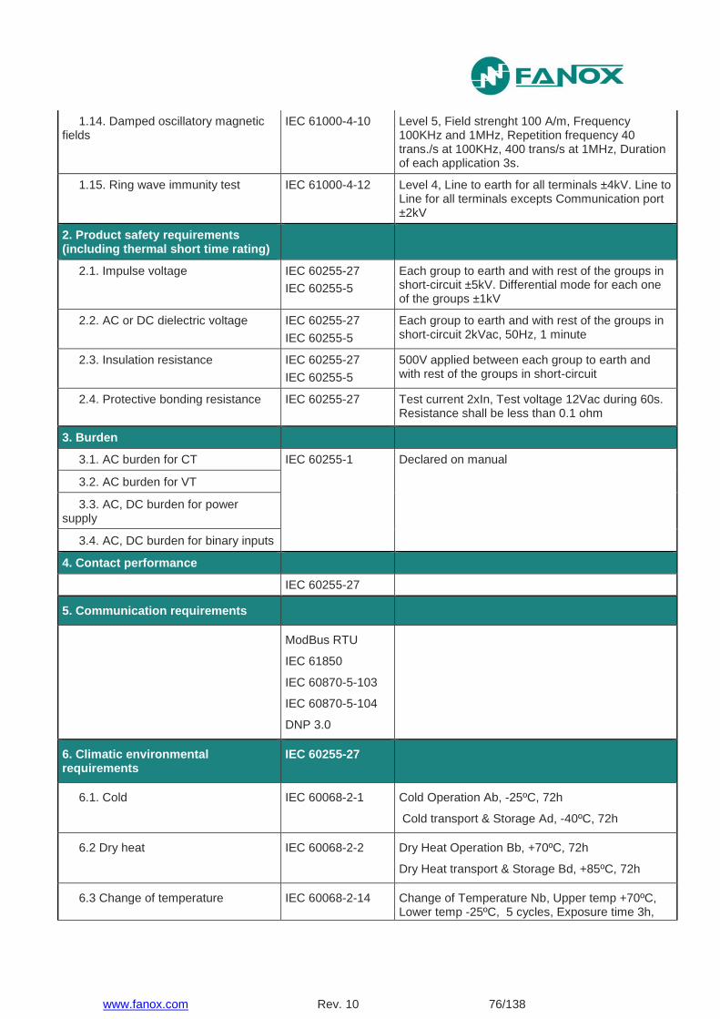
www.fanox.com Rev. 10 76/138
1.14. Damped oscillatory magnetic fields
IEC 61000-4-10 Level 5, Field strenght 100 A/m, Frequency 100KHz and 1MHz, Repetition frequency 40 trans./s at 100KHz, 400 trans/s at 1MHz, Duration of each application 3s.
1.15. Ring wave immunity test IEC 61000-4-12 Level 4, Line to earth for all terminals ±4kV. Line to Line for all terminals excepts Communication port ±2kV
2. Product safety requirements (including thermal short time rating)
2.1. Impulse voltage IEC 60255-27
IEC 60255-5
Each group to earth and with rest of the groups in short-circuit ±5kV. Differential mode for each one of the groups ±1kV
2.2. AC or DC dielectric voltage IEC 60255-27
IEC 60255-5
Each group to earth and with rest of the groups in short-circuit 2kVac, 50Hz, 1 minute
2.3. Insulation resistance IEC 60255-27
IEC 60255-5
500V applied between each group to earth and with rest of the groups in short-circuit
2.4. Protective bonding resistance IEC 60255-27 Test current 2xIn, Test voltage 12Vac during 60s. Resistance shall be less than 0.1 ohm
3. Burden
3.1. AC burden for CT IEC 60255-1 Declared on manual
3.2. AC burden for VT
3.3. AC, DC burden for power supply
3.4. AC, DC burden for binary inputs
4. Contact performance
IEC 60255-27
5. Communication requirements
ModBus RTU
IEC 61850
IEC 60870-5-103
IEC 60870-5-104
DNP 3.0
6. Climatic environmental requirements
IEC 60255-27
6.1. Cold IEC 60068-2-1 Cold Operation Ab, -25ºC, 72h
Cold transport & Storage Ad, -40ºC, 72h
6.2 Dry heat IEC 60068-2-2 Dry Heat Operation Bb, +70ºC, 72h
Dry Heat transport & Storage Bd, +85ºC, 72h
6.3 Change of temperature IEC 60068-2-14 Change of Temperature Nb, Upper temp +70ºC, Lower temp -25ºC, 5 cycles, Exposure time 3h,
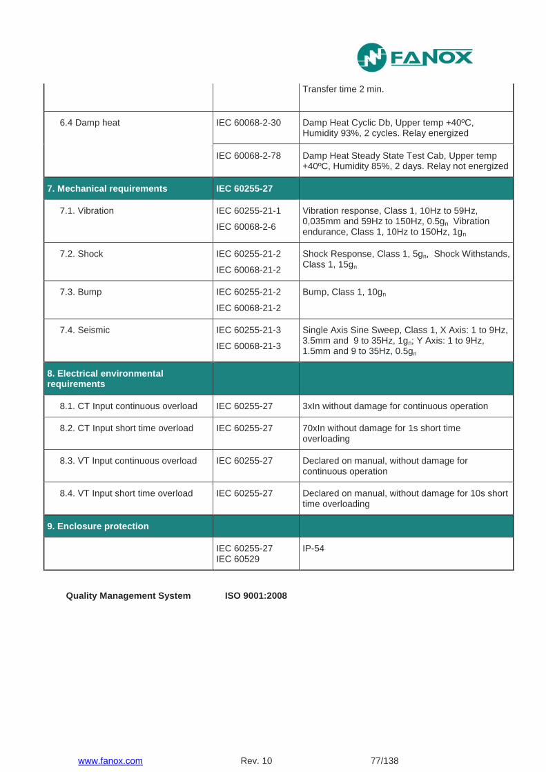
www.fanox.com Rev. 10 77/138
Transfer time 2 min.
6.4 Damp heat IEC 60068-2-30 Damp Heat Cyclic Db, Upper temp +40ºC, Humidity 93%, 2 cycles. Relay energized
IEC 60068-2-78 Damp Heat Steady State Test Cab, Upper temp +40ºC, Humidity 85%, 2 days. Relay not energized
7. Mechanical requirements IEC 60255-27
7.1. Vibration IEC 60255-21-1
IEC 60068-2-6
Vibration response, Class 1, 10Hz to 59Hz, 0,035mm and 59Hz to 150Hz, 0.5gn Vibration endurance, Class 1, 10Hz to 150Hz, 1gn
7.2. Shock IEC 60255-21-2
IEC 60068-21-2
Shock Response, Class 1, 5gn, Shock Withstands, Class 1, 15gn
7.3. Bump IEC 60255-21-2
IEC 60068-21-2
Bump, Class 1, 10gn
7.4. Seismic IEC 60255-21-3
IEC 60068-21-3
Single Axis Sine Sweep, Class 1, X Axis: 1 to 9Hz, 3.5mm and 9 to 35Hz, 1gn; Y Axis: 1 to 9Hz, 1.5mm and 9 to 35Hz, 0.5gn
8. Electrical environmental requirements
8.1. CT Input continuous overload IEC 60255-27 3xIn without damage for continuous operation
8.2. CT Input short time overload IEC 60255-27 70xIn without damage for 1s short time overloading
8.3. VT Input continuous overload IEC 60255-27 Declared on manual, without damage for continuous operation
8.4. VT Input short time overload IEC 60255-27 Declared on manual, without damage for 10s short time overloading
9. Enclosure protection
IEC 60255-27 IEC 60529
IP-54
Quality Management System ISO 9001:2008
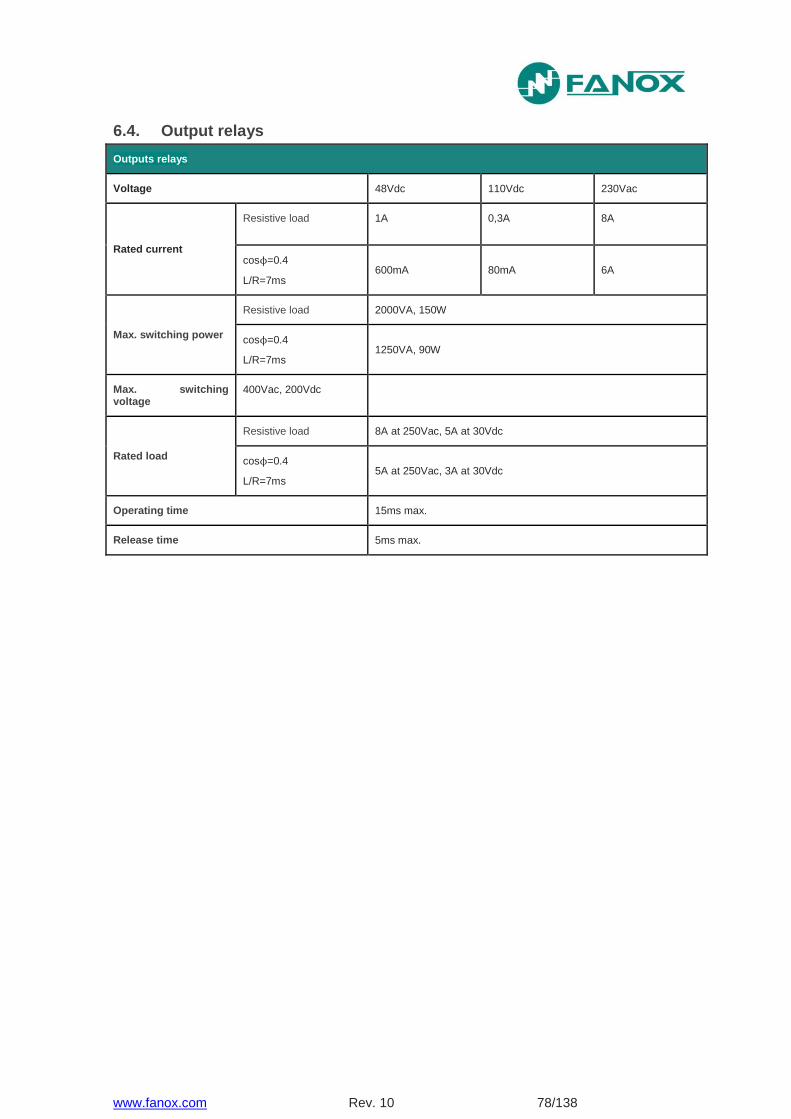
www.fanox.com Rev. 10 78/138
6.4. Output relays
Outputs relays
Voltage 48Vdc 110Vdc 230Vac
Rated current
Resistive load 1A 0,3A 8A
cosϕ=0.4
L/R=7ms 600mA 80mA 6A
Max. switching power
Resistive load 2000VA, 150W
cosϕ=0.4
L/R=7ms 1250VA, 90W
Max. switching voltage
400Vac, 200Vdc
Rated load
Resistive load 8A at 250Vac, 5A at 30Vdc
cosϕ=0.4
L/R=7ms 5A at 250Vac, 3A at 30Vdc
Operating time 15ms max.
Release time 5ms max.
www.fanox.com Rev. 10 79/138
7. COMMUNICATION AND HMI
7.1. Front Communication: USB
One communications port is installed on the front of the equipment. The connector that is used is a mini USB (connector mini USB type A). The protocol that is used is Modbus RTU (19200 -8bit – no parity – 1 stop bit). The protocol map and documentation that are used are attached in an appendix to this manual.
The USB cable allows the power supply and the communication simultaneously.
The PC earth should be connected to the same earth as the relay to avoid communication problems.
For writing commands it is necessary to set up a communication session (identification command) which it will be closed after a period of time without communication. To set up a communication session it will be necessary a password. For writing commands the password will be adjustable.
7.2. Rear Communication: RS485
An option exists to fit the SIA-F with a rear communications port RS485, to communicate with SCADA or RTU system.
The RS485 port output has two terminals -, +), located on the rear of the equipment. The protocol that is used is ModBus RTU (8bit – no parity – 1 stop bit).
The protocol map and documentation that are used are attached in 8.ModBus RTU protocol.
This port can be used to continuously monitor the equipment from a remote PC or SCADA system. Up to 32 pieces of equipment can be connected to one bus; each piece with a different ModBus address. The equipment ModBus address and baudrate can be configured using the communications or from HMI.
For writing commands it is necessary to open a communication session (identification command) which it will be closed after a period of time without communication. To open a communication session it will be necessary a password
To minimize communication errors as a result of noise, the use of a stranded and shielded cable is recommended for the physical connection. All of the + terminals on one side, and all of the - terminals on the other must be connected together in order to make the connection.
If a 2 strand cable is used for communication, the GND terminals must be connected to the shielding. The shielding must be connected to the GND at only one point to avoid circular currents.
Resistors should be used at each end if very long cables are used. The best solution for avoiding reflection is to install resistors at both ends of the cable. The ohm value of these resistors must be equal to the cable impedance value. Fiber optics can be used in very aggressive environments, and they are connected by using the corresponding converters.
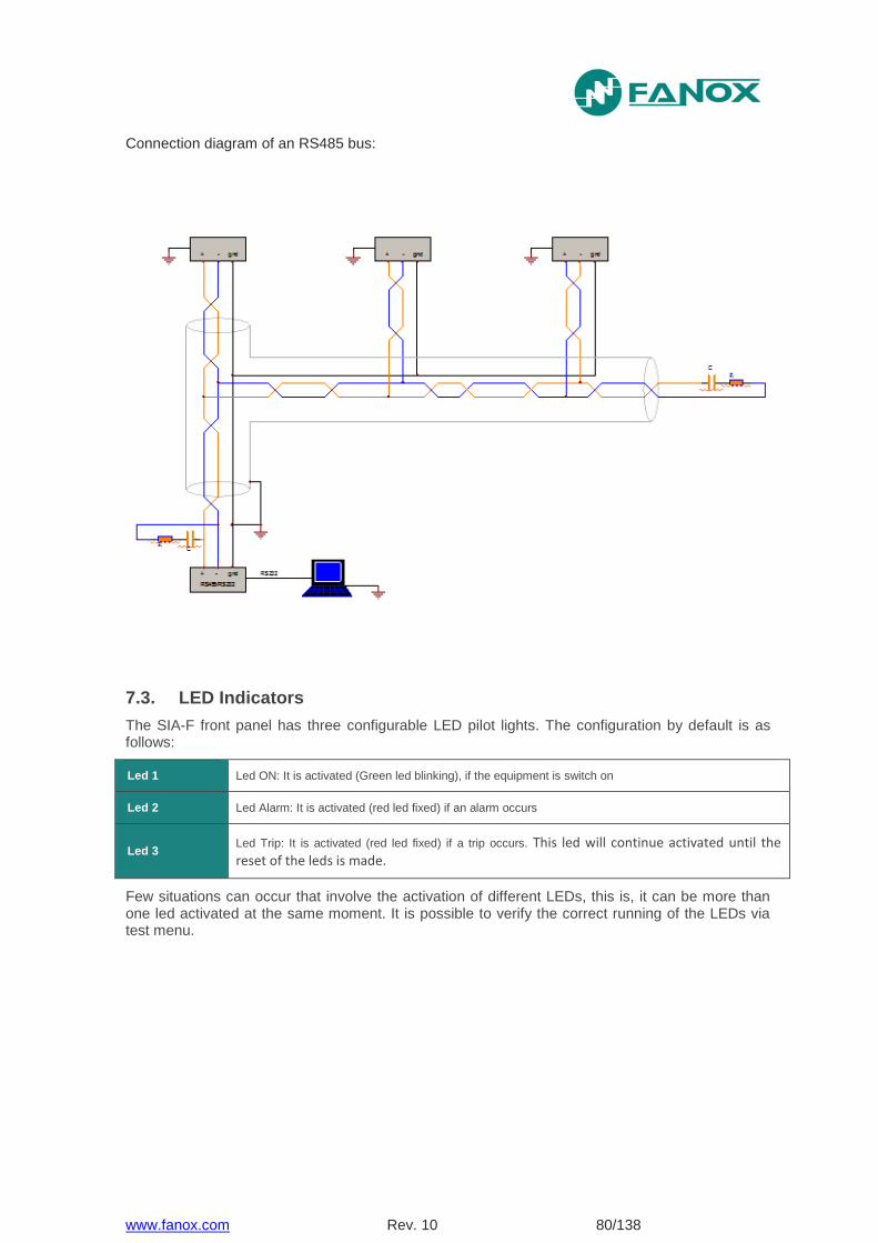
www.fanox.com Rev. 10 80/138
Connection diagram of an RS485 bus:
7.3. LED Indicators
The SIA-F front panel has three configurable LED pilot lights. The configuration by default is as follows:
Led 1 Led ON: It is activated (Green led blinking), if the equipment is switch on
Led 2 Led Alarm: It is activated (red led fixed) if an alarm occurs
Led 3 Led Trip: It is activated (red led fixed) if a trip occurs. This led will continue activated until the reset of the leds is made.
Few situations can occur that involve the activation of different LEDs, this is, it can be more than one led activated at the same moment. It is possible to verify the correct running of the LEDs via test menu.

www.fanox.com Rev. 10 81/138
7.4. LCD and keypad
The front of the SIA-F relay is fitted with an alphanumeric LCD screen, measuring 20x2. This screen provides the user with access to read information about the settings parameters, measurements, state and events. All of this information is arranged in a system of menus.
A keypad is fitted to the relay front panel, which can be used to access the information shown on the LCD screen and to navigate through the menu system.
This membrane keyboard has 6 keys that can be used to navigate through the different menus and to change the setting parameters. The ▲ ▼ and ◄ ► keys can be used to navigate through the different menus, the different options in each menu and the different values for the settings parameters.
The “OK” key is used to access the menus and the different options, as well as to approve changes to values. The “C” key is used to delete and to go back through the menu levels.
As well as the 6 keys, there is also a "Reset" key. When “Reset” is pressed, the alarm led and the trip led return to their initial position. The “Reset” key can also be used to delete all of the events in the "Events" menu.
7.5. SICom Communications program
The SICom program, which works with the Windows 7, Windows 8, Windows 8.1 or Windows 10 operating system is provided, and can be used to gain access to all of the equipment information, to modify the settings and to save events using a graphic user interface.
The following operations can be carried out using the SICom program:
State reading
Measurement reading
Reading and changing settings
Reading and deleting events
Reading and deleting fault reports
Changing the user passwords
Loading settings files
Loading configuration files
Date-time synchronization
Checking the versions of the equipment
Configuring the Modbus address
Reading and changing counters
Processes for opening and closing the circuit breaker
Configuration of the inputs
Configuration of the outputs
Configuration of the causes that start a Fault Report

www.fanox.com Rev. 10 82/138
7.5.1. How to install SICOM Software
To install the SICom it is necessary the following link:
http://fanox.blob.core.windows.net/sicom/publish.htm
The link will open the next screen, where key “install” must be pressed:
The necessary drivers depending on the operative system can be downloaded from this page.
The update of the software does not required any user´s action, this is, if the computer is
connected to Internet, SICom updates itself when it is started.
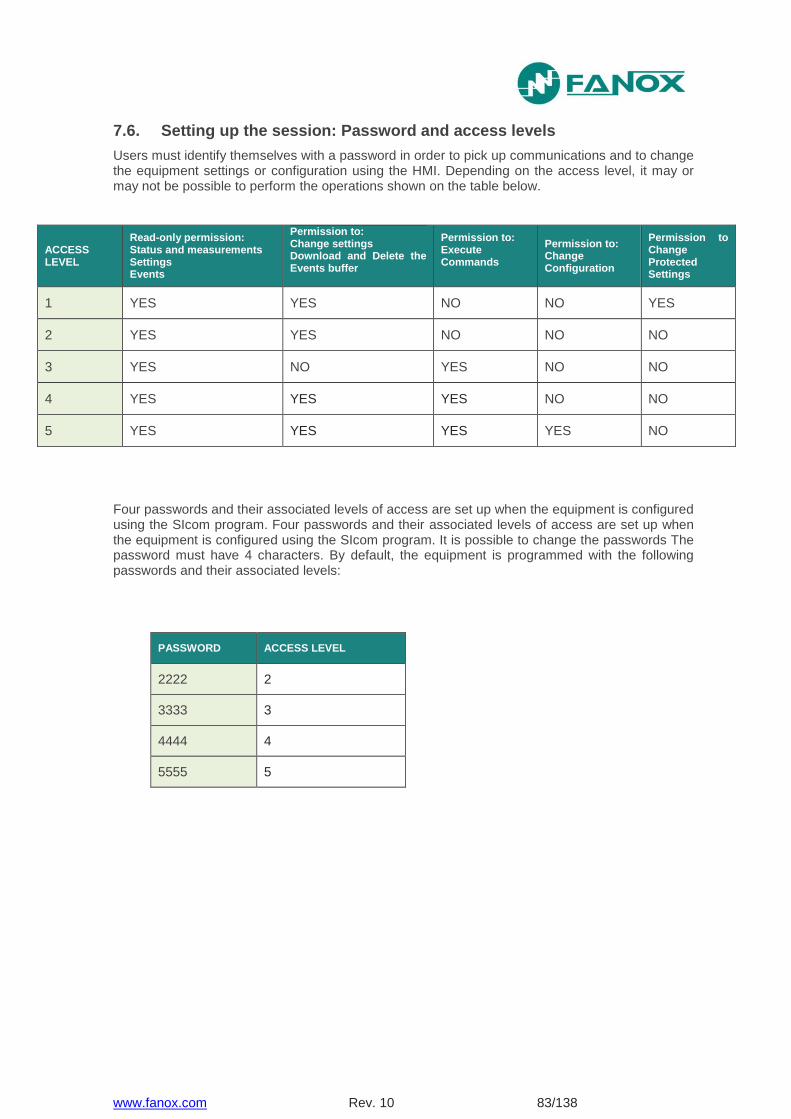
www.fanox.com Rev. 10 83/138
7.6. Setting up the session: Password and access levels
Users must identify themselves with a password in order to pick up communications and to change the equipment settings or configuration using the HMI. Depending on the access level, it may or may not be possible to perform the operations shown on the table below.
ACCESS LEVEL
Read-only permission: Status and measurements Settings Events
Permission to: Change settings Download and Delete the Events buffer
Permission to: Execute Commands
Permission to: Change Configuration
Permission to Change Protected Settings
1 YES YES NO NO YES
2 YES YES NO NO NO
3 YES NO YES NO NO
4 YES YES YES NO NO
5 YES YES YES YES NO
Four passwords and their associated levels of access are set up when the equipment is configured using the SIcom program. Four passwords and their associated levels of access are set up when the equipment is configured using the SIcom program. It is possible to change the passwords The password must have 4 characters. By default, the equipment is programmed with the following passwords and their associated levels:
PASSWORD ACCESS LEVEL
2222 2
3333 3
4444 4
5555 5
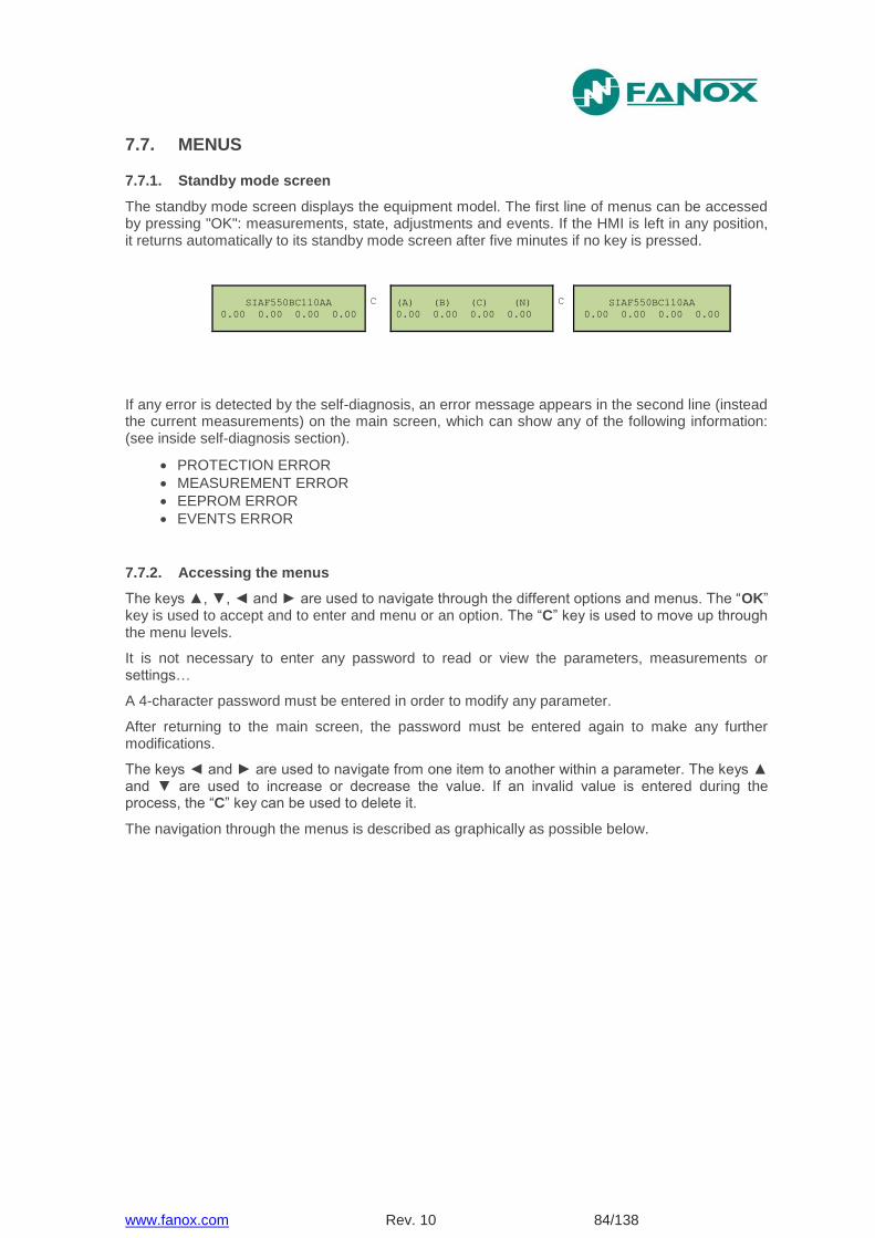
www.fanox.com Rev. 10 84/138
7.7. MENUS
7.7.1. Standby mode screen
The standby mode screen displays the equipment model. The first line of menus can be accessed by pressing "OK": measurements, state, adjustments and events. If the HMI is left in any position, it returns automatically to its standby mode screen after five minutes if no key is pressed.
SIAF550BC110AA
0.00 0.00 0.00 0.00
C (A) (B) (C) (N)
0.00 0.00 0.00 0.00
C SIAF550BC110AA
0.00 0.00 0.00 0.00
If any error is detected by the self-diagnosis, an error message appears in the second line (instead the current measurements) on the main screen, which can show any of the following information: (see inside self-diagnosis section).
PROTECTION ERROR
MEASUREMENT ERROR
EEPROM ERROR
EVENTS ERROR
7.7.2. Accessing the menus
The keys ▲, ▼, ◄ and ► are used to navigate through the different options and menus. The “OK” key is used to accept and to enter and menu or an option. The “C” key is used to move up through the menu levels.
It is not necessary to enter any password to read or view the parameters, measurements or settings…
A 4-character password must be entered in order to modify any parameter.
After returning to the main screen, the password must be entered again to make any further modifications.
The keys ◄ and ► are used to navigate from one item to another within a parameter. The keys ▲ and ▼ are used to increase or decrease the value. If an invalid value is entered during the process, the “C” key can be used to delete it.
The navigation through the menus is described as graphically as possible below.
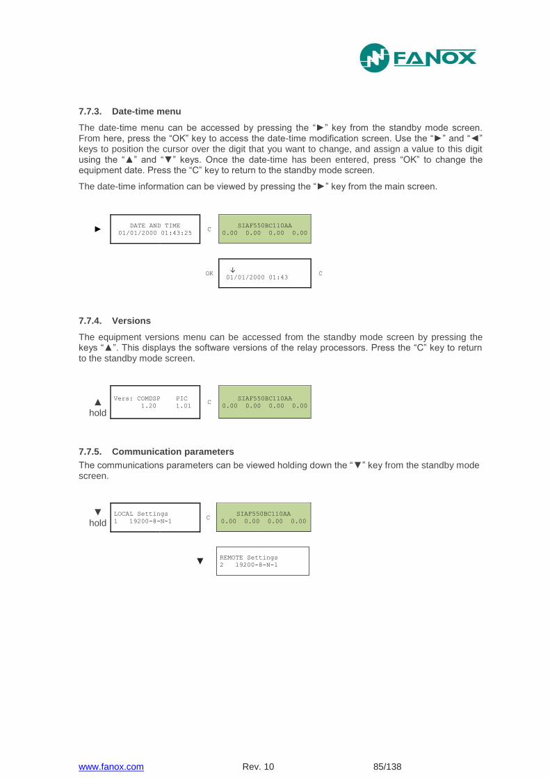
www.fanox.com Rev. 10 85/138
7.7.3. Date-time menu
The date-time menu can be accessed by pressing the “►” key from the standby mode screen. From here, press the “OK” key to access the date-time modification screen. Use the “►” and “◄” keys to position the cursor over the digit that you want to change, and assign a value to this digit using the “▲” and “▼” keys. Once the date-time has been entered, press “OK” to change the equipment date. Press the “C” key to return to the standby mode screen.
The date-time information can be viewed by pressing the “►” key from the main screen.
► DATE AND TIME
01/01/2000 01:43:25 C
SIAF550BC110AA
0.00 0.00 0.00 0.00
OK ↓
01/01/2000 01:43 C
7.7.4. Versions
The equipment versions menu can be accessed from the standby mode screen by pressing the keys “▲”. This displays the software versions of the relay processors. Press the “C” key to return to the standby mode screen.
▲
hold
Vers: COMDSP PIC
1.20 1.01 C
SIAF550BC110AA
0.00 0.00 0.00 0.00
7.7.5. Communication parameters
The communications parameters can be viewed holding down the “▼” key from the standby mode screen.
▼ hold
LOCAL Settings
1 19200-8-N-1 C
SIAF550BC110AA
0.00 0.00 0.00 0.00
▼
REMOTE Settings
2 19200-8-N-1

www.fanox.com Rev. 09 86/138
7.7.6. Test Menu
The “Test menu” is accessed from the standby mode screen by sequentially pressing the “◄”, “▼” and “►” keys, and then holding down the “OK” key. From
here, press “OK” to access the components that can be tested.
◄ ▼ ►
OK hold
TEST MENU y/n?
without protection! C
OK Set Password
-> 0 C
◄▼▲► Set Password
-> 5555 C
OK TEST MENU
C
OK Led 1:
not activated C
OK Led 1:
<<ACTIVATED>> OK
▲▼ Led 2:
not activated C
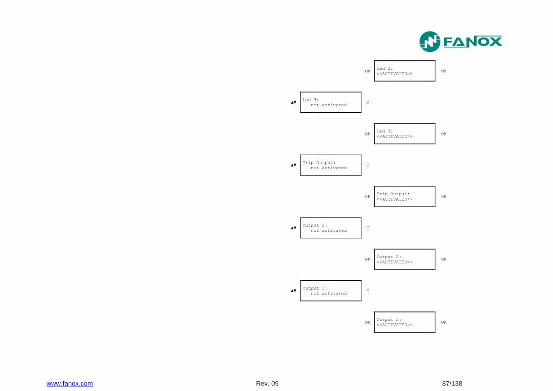
www.fanox.com Rev. 09 87/138
OK Led 2:
<<ACTIVATED>> OK
▲▼ Led 3:
not activated C
OK Led 3:
<<ACTIVATED>> OK
▲▼ Trip Output:
not activated C
OK Trip Output:
<<ACTIVATED>> OK
▲▼ Output 2:
not activated C
OK Output 2:
<<ACTIVATED>> OK
▲▼ Output 3:
not activated C
OK Output 3:
<<ACTIVATED>> OK
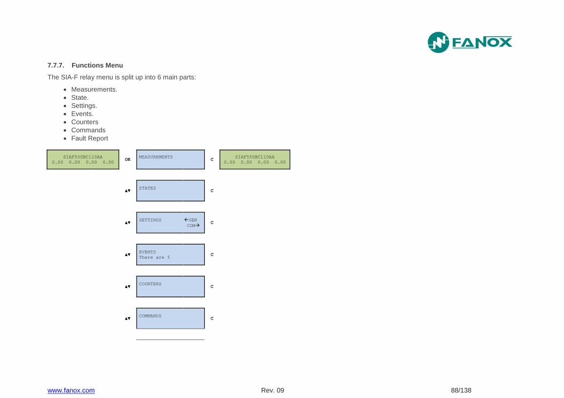
www.fanox.com Rev. 09 88/138
7.7.7. Functions Menu
The SIA-F relay menu is split up into 6 main parts:
Measurements.
State.
Settings.
Events.
Counters
Commands
Fault Report
SIAF550BC110AA
0.00 0.00 0.00 0.00 OK
MEASUREMENTS
C
SIAF550BC110AA
0.00 0.00 0.00 0.00
▲▼ STATES
C
▲▼ SETTINGS GEN
COM C
▲▼ EVENTS
There are 5 C
▲▼ COUNTERS
C
▲▼ COMMANDS
C
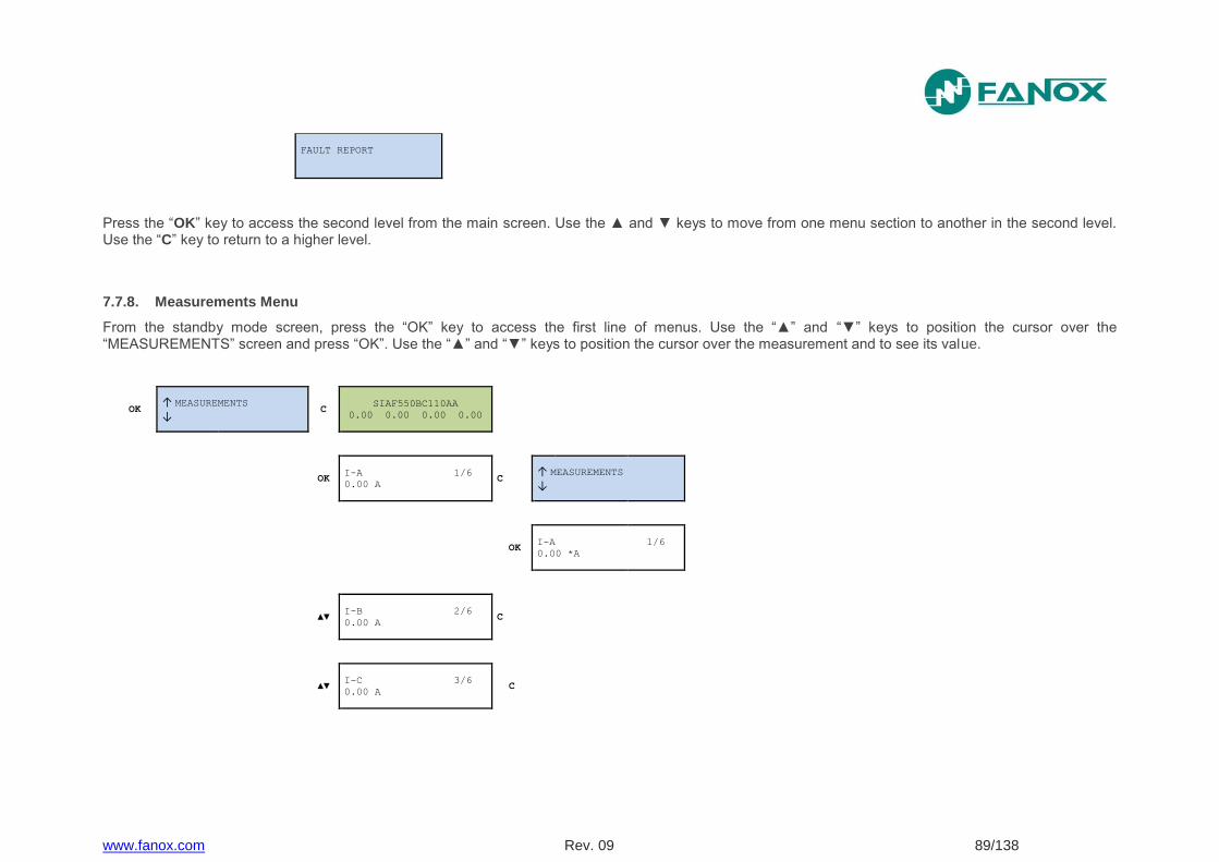
www.fanox.com Rev. 09 89/138
FAULT REPORT
Press the “OK” key to access the second level from the main screen. Use the ▲ and ▼ keys to move from one menu section to another in the second level. Use the “C” key to return to a higher level.
7.7.8. Measurements Menu
From the standby mode screen, press the “OK” key to access the first line of menus. Use the “▲” and “▼” keys to position the cursor over the “MEASUREMENTS” screen and press “OK”. Use the “▲” and “▼” keys to position the cursor over the measurement and to see its value.
OK ↑ MEASUREMENTS ↓
C SIAF550BC110AA
0.00 0.00 0.00 0.00
OK I-A 1/6
0.00 A C
↑ MEASUREMENTS ↓
OK
I-A 1/6
0.00 *A
▲▼ I-B 2/6
0.00 A C
▲▼ I-C 3/6
0.00 A C
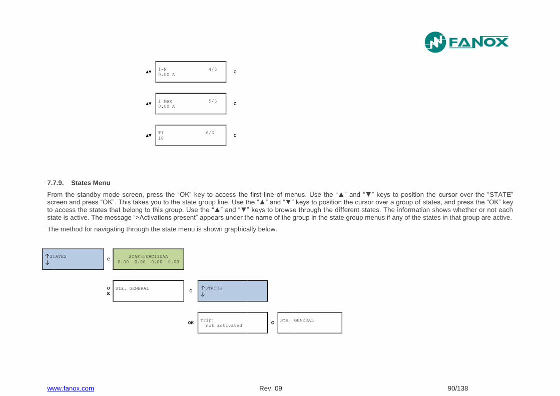
www.fanox.com Rev. 09 90/138
▲▼ I-N 4/6
0.00 A C
▲▼ I Max 5/6
0.00 A C
▲▼ TI 6/6
10 C
7.7.9. States Menu
From the standby mode screen, press the “OK” key to access the first line of menus. Use the “▲” and “▼” keys to position the cursor over the “STATE” screen and press “OK”. This takes you to the state group line. Use the “▲” and “▼” keys to position the cursor over a group of states, and press the “OK” key to access the states that belong to this group. Use the “▲” and “▼” keys to browse through the different states. The information shows whether or not each state is active. The message “>Activations present” appears under the name of the group in the state group menus if any of the states in that group are active.
The method for navigating through the state menu is shown graphically below.
↑STATES
↓ C
SIAF550BC110AA
0.00 0.00 0.00 0.00
O
K
Sta. GENERAL
C
↑STATES
↓
OK Trip:
not activated C
Sta. GENERAL
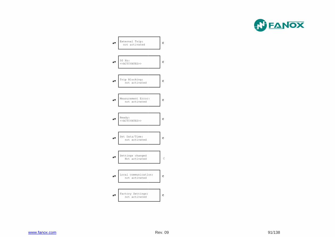
www.fanox.com Rev. 09 91/138
▲▼ External Trip:
not activated C
▲▼ 50 Hz:
<<ACTIVATED>> C
▲▼ Trip Blocking:
not activated C
▲▼ Measurement Error:
not activated C
▲▼ Ready:
<<ACTIVATED>> C
▲▼ Set Data/Time:
not activated C
▲▼
Settings changed
Not activated C
▲▼ Local communication:
not activated C
▲▼ Factory Settings:
not activated C
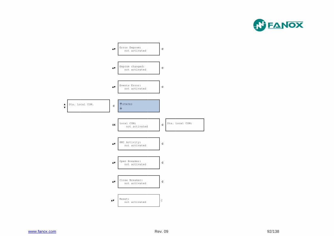
www.fanox.com Rev. 09 92/138
▲▼ Error Eeprom:
not activated C
▲▼ Eeprom changed:
not activated C
▲▼ Events Error:
not activated C
▲
▼
Sta. Local COM.
C
↑STATES
↓
OK Local COM:
not activated C
Sta. Local COM:
▲▼ HMI Activity:
not activated C
▲▼ Open Breaker:
not activated C
▲▼ Close Breaker:
not activated C
▲▼ Reset:
not activated C
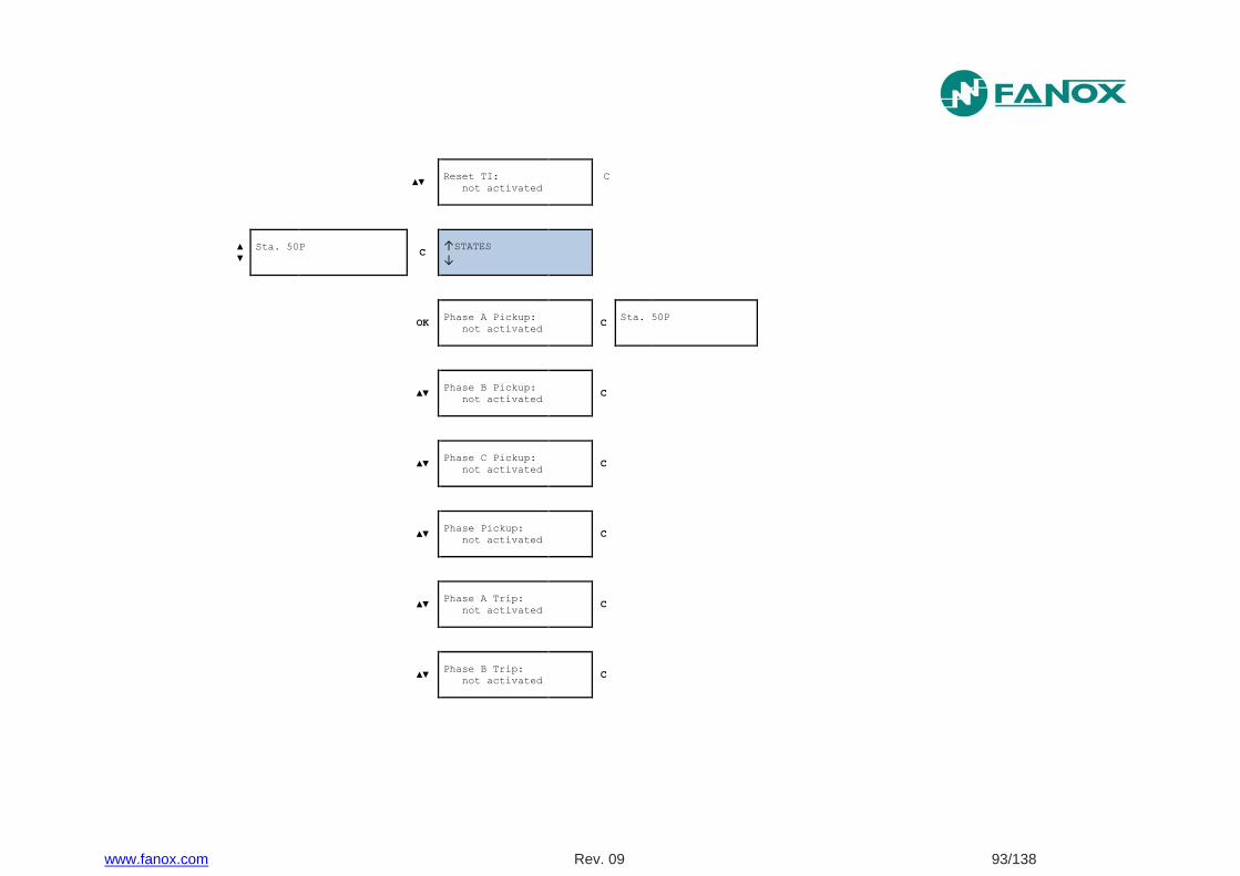
www.fanox.com Rev. 09 93/138
▲▼ Reset TI:
not activated
C
▲
▼
Sta. 50P
C
↑STATES
↓
OK Phase A Pickup:
not activated C
Sta. 50P
▲▼ Phase B Pickup:
not activated C
▲▼ Phase C Pickup:
not activated C
▲▼ Phase Pickup:
not activated C
▲▼ Phase A Trip:
not activated C
▲▼ Phase B Trip:
not activated C
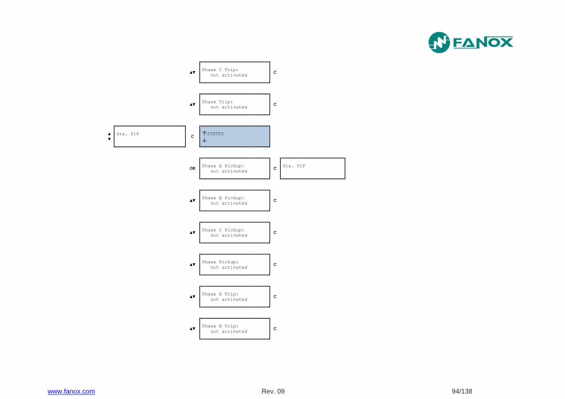
www.fanox.com Rev. 09 94/138
▲▼ Phase C Trip:
not activated C
▲▼ Phase Trip:
not activated C
▲
▼
Sta. 51P
C
↑STATES
↓
OK Phase A Pickup:
not activated C
Sta. 51P
▲▼ Phase B Pickup:
not activated C
▲▼ Phase C Pickup:
not activated C
▲▼ Phase Pickup:
not activated C
▲▼ Phase A Trip:
not activated C
▲▼ Phase B Trip:
not activated C

www.fanox.com Rev. 09 95/138
▲▼ Phase C Trip:
not activated C
▲▼ Phase Trip:
not activated C
▲
▼
Sta. 50N
C
↑STATES
↓
OK Ground Pickup:
not activated C
Sta. 50N
▲▼ Ground Trip:
not activated C
▲
▼
Sta. 51N
C
↑STATES
↓
OK Ground Pickup:
not activated C
Sta. 51N
▲▼ Ground Trip:
not activated C
Sta. CLP
>CLP Disable
CLP Disable
Activated C
Sta. CLP
>CLP Disable
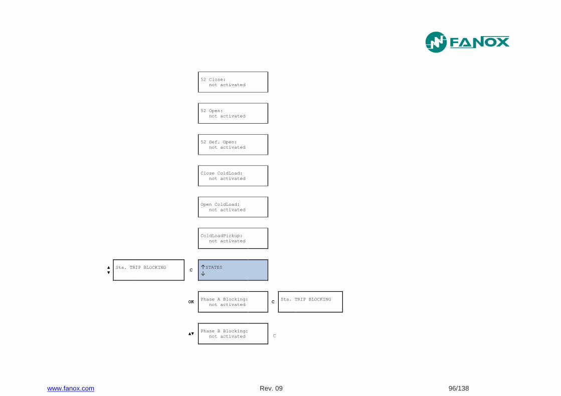
www.fanox.com Rev. 09 96/138
52 Close:
not activated
52 Open:
not activated
52 Def. Open:
not activated
Close ColdLoad:
not activated
Open ColdLoad:
not activated
ColdLoadPickup:
not activated
▲
▼
Sta. TRIP BLOCKING
C
↑STATES
↓
OK Phase A Blocking:
not activated C
Sta. TRIP BLOCKING
▲▼
Phase B Blocking:
not activated C
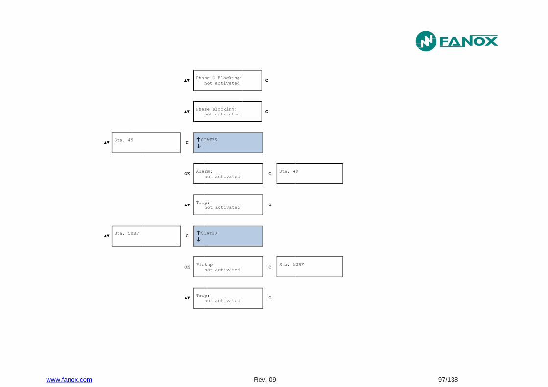
www.fanox.com Rev. 09 97/138
▲▼ Phase C Blocking:
not activated C
▲▼ Phase Blocking:
not activated C
▲▼ Sta. 49
C
↑STATES
↓
OK Alarm:
not activated C
Sta. 49
▲▼ Trip:
not activated C
▲▼ Sta. 50BF
C
↑STATES
↓
OK Pickup:
not activated C
Sta. 50BF
▲▼ Trip:
not activated C

www.fanox.com Rev. 09 98/138
▲▼ Sta. 52
>52 Close C
↑STATES
↓
OK 52 Startup:
not activated C
Sta. 52
>52 Close
▲▼ 52 Error:
not activated C
▲▼ 52 Open:
not activated C
▲▼ 52 Open Time:
not activated C
▲▼ 52 Open Error:
<<ACTIVATED>> C
▲▼ 52 Close:
not activated C
▲▼ 52 Close Time:
not activated C
▲▼ 52 Close Error:
not activated C
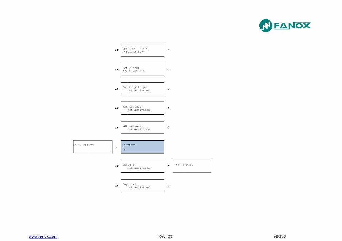
www.fanox.com Rev. 09 99/138
▲▼ Open Num. Alarm:
<<ACTIVATED>> C
▲▼ I2t Alarm:
<<ACTIVATED>> C
▲▼ Too Many Trips:
not activated C
▲▼ 52A contact:
not activated C
▲▼ 52B contact:
not activated C
Sta. INPUTS
C
↑STATES
↓
▲▼ Input 1:
not activated C
Sta. INPUTS
▲▼ Input 2:
not activated C
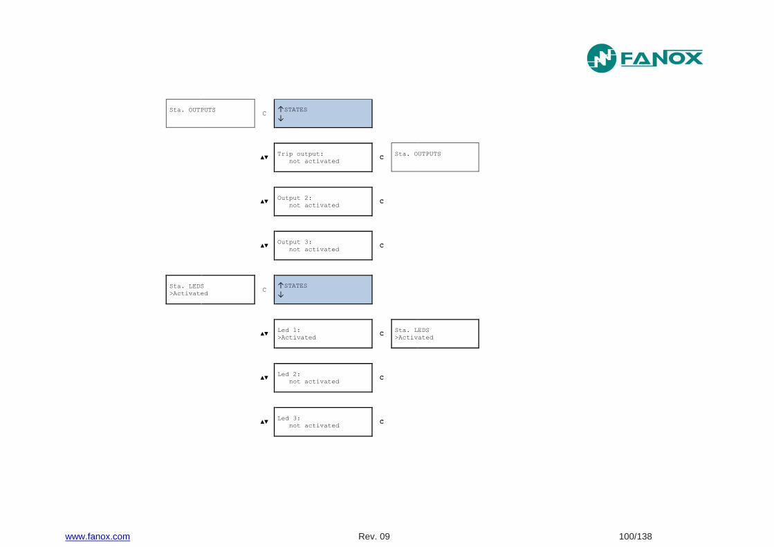
www.fanox.com Rev. 09 100/138
Sta. OUTPUTS
C
↑STATES
↓
▲▼ Trip output:
not activated C
Sta. OUTPUTS
▲▼ Output 2:
not activated C
▲▼ Output 3:
not activated C
Sta. LEDS
>Activated C
↑STATES
↓
▲▼ Led 1:
>Activated C
Sta. LEDS
>Activated
▲▼ Led 2:
not activated C
▲▼ Led 3:
not activated C

www.fanox.com Rev. 09 101/138
Sta. LOGIC
↑STATES
↓
▲▼ 52a:
not activated C
Sta. LOGIC
▲▼ 52b:
not activated C
▲▼ Ext Trip:
not activated C
▲▼ 50BF Init:
not activated C
▲▼ Fault Init:
not activated C
▲▼ Blck. 50P:
not activated C
▲▼ Blck. 50N:
not activated C
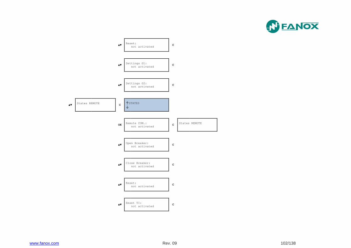
www.fanox.com Rev. 09 102/138
▲▼ Reset:
not activated C
▲▼ Settings G1:
not activated C
▲▼ Settings G2:
not activated C
▲▼ States REMOTE
C
↑STATES
↓
OK Remote COM.:
not activated C
States REMOTE
▲▼ Open Breaker:
not activated C
▲▼ Close Breaker:
not activated C
▲▼ Reset:
not activated C
▲▼ Reset TI:
not activated C
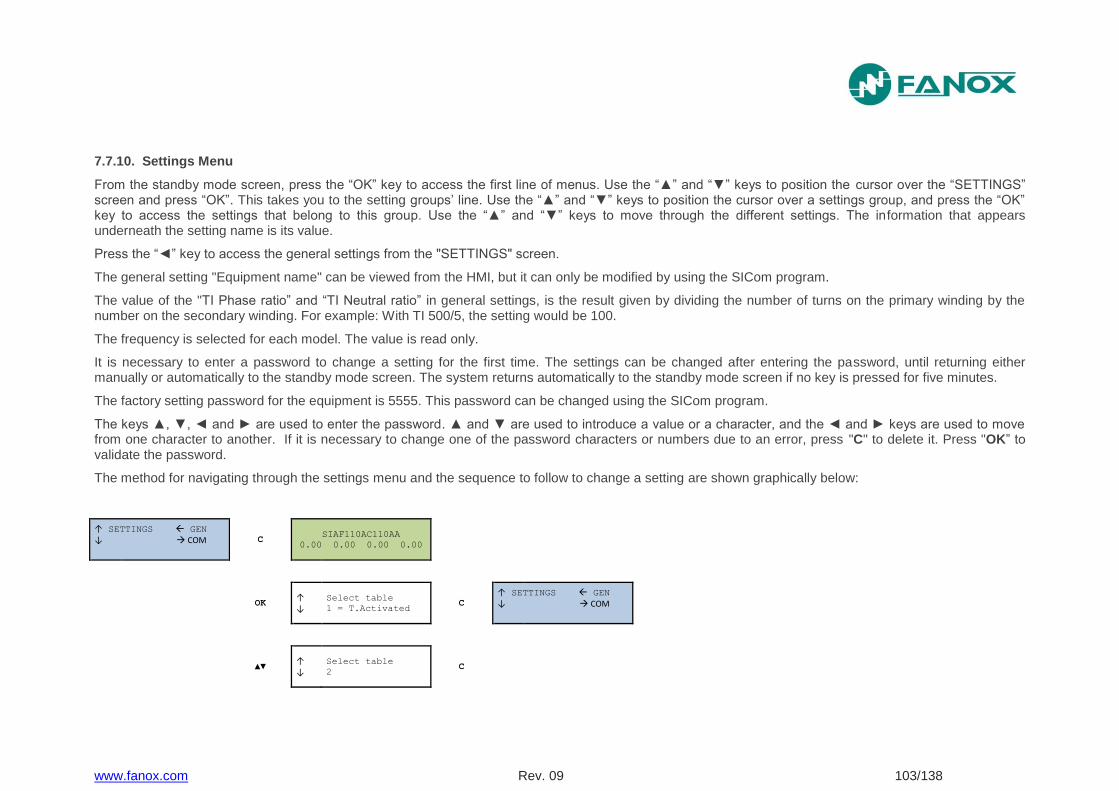
www.fanox.com Rev. 09 103/138
7.7.10. Settings Menu
From the standby mode screen, press the “OK” key to access the first line of menus. Use the “▲” and “▼” keys to position the cursor over the “SETTINGS” screen and press “OK”. This takes you to the setting groups’ line. Use the “▲” and “▼” keys to position the cursor over a settings group, and press the “OK” key to access the settings that belong to this group. Use the “▲” and “▼” keys to move through the different settings. The information that appears underneath the setting name is its value.
Press the “◄” key to access the general settings from the "SETTINGS" screen.
The general setting "Equipment name" can be viewed from the HMI, but it can only be modified by using the SICom program.
The value of the "TI Phase ratio” and “TI Neutral ratio” in general settings, is the result given by dividing the number of turns on the primary winding by the number on the secondary winding. For example: With TI 500/5, the setting would be 100.
The frequency is selected for each model. The value is read only.
It is necessary to enter a password to change a setting for the first time. The settings can be changed after entering the password, until returning either manually or automatically to the standby mode screen. The system returns automatically to the standby mode screen if no key is pressed for five minutes.
The factory setting password for the equipment is 5555. This password can be changed using the SICom program.
The keys ▲, ▼, ◄ and ► are used to enter the password. ▲ and ▼ are used to introduce a value or a character, and the ◄ and ► keys are used to move from one character to another. If it is necessary to change one of the password characters or numbers due to an error, press "C" to delete it. Press "OK” to validate the password.
The method for navigating through the settings menu and the sequence to follow to change a setting are shown graphically below:
↑ SETTINGS GEN
↓ COM
C SIAF110AC110AA
0.00 0.00 0.00 0.00
OK ↑
↓
Select table
1 = T.Activated C
↑ SETTINGS GEN
↓ COM
▲▼ ↑
↓
Select table
2 C
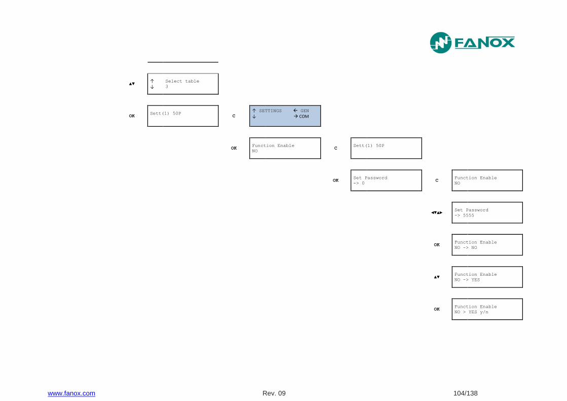
www.fanox.com Rev. 09 104/138
▲▼ ↑
↓
Select table
3
OK Sett(1) 50P
C
↑ SETTINGS GEN
↓ COM
OK Function Enable
NO C
Sett(1) 50P
OK
Set Password
-> 0 C
Function Enable
NO
◄▼▲► Set Password
-> 5555
OK Function Enable
NO -> NO
▲▼ Function Enable
NO -> YES
OK Function Enable
NO > YES y/n
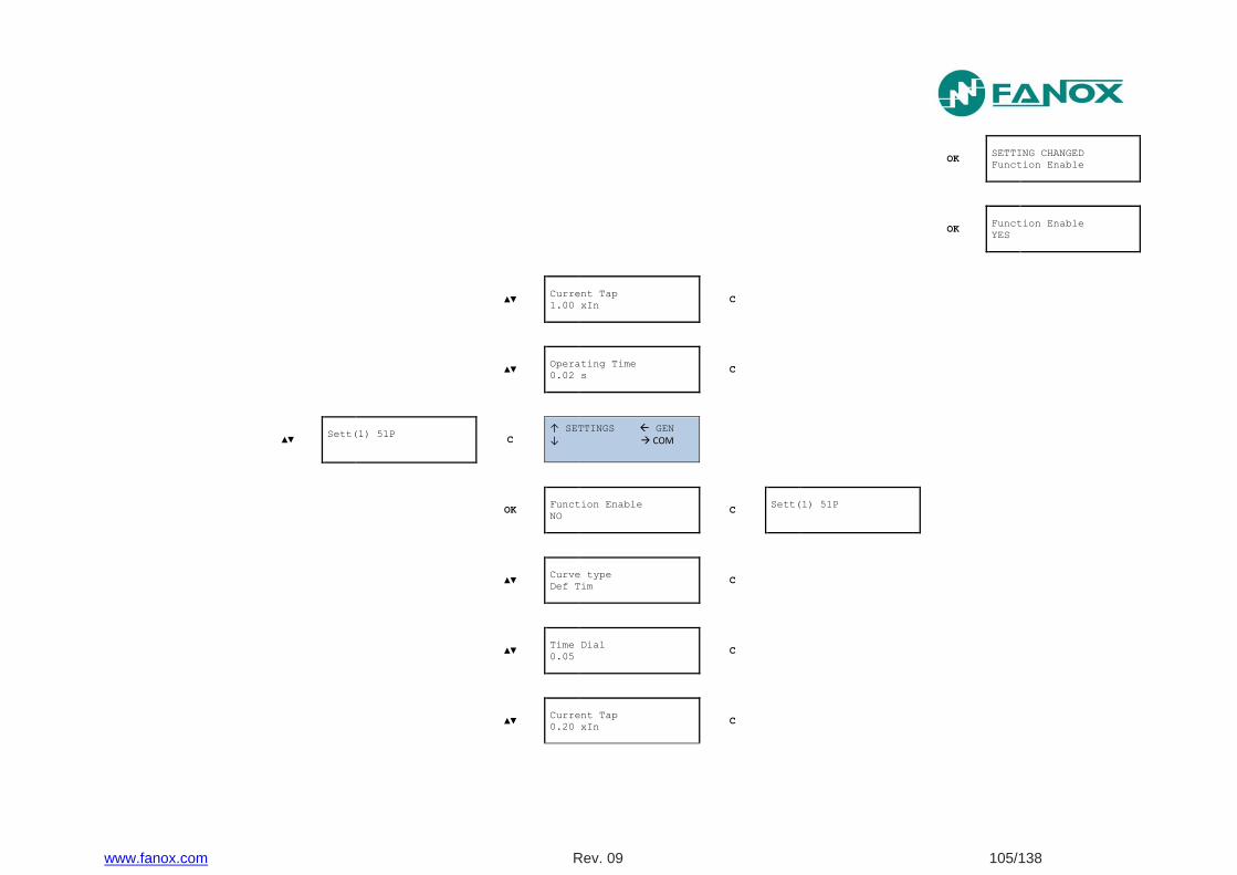
www.fanox.com Rev. 09 105/138
OK SETTING CHANGED
Function Enable
OK Function Enable
YES
▲▼ Current Tap
1.00 xIn C
▲▼ Operating Time
0.02 s C
▲▼ Sett(1) 51P
C
↑ SETTINGS GEN
↓ COM
OK Function Enable
NO C
Sett(1) 51P
▲▼ Curve type
Def Tim C
▲▼ Time Dial
0.05 C
▲▼ Current Tap
0.20 xIn C
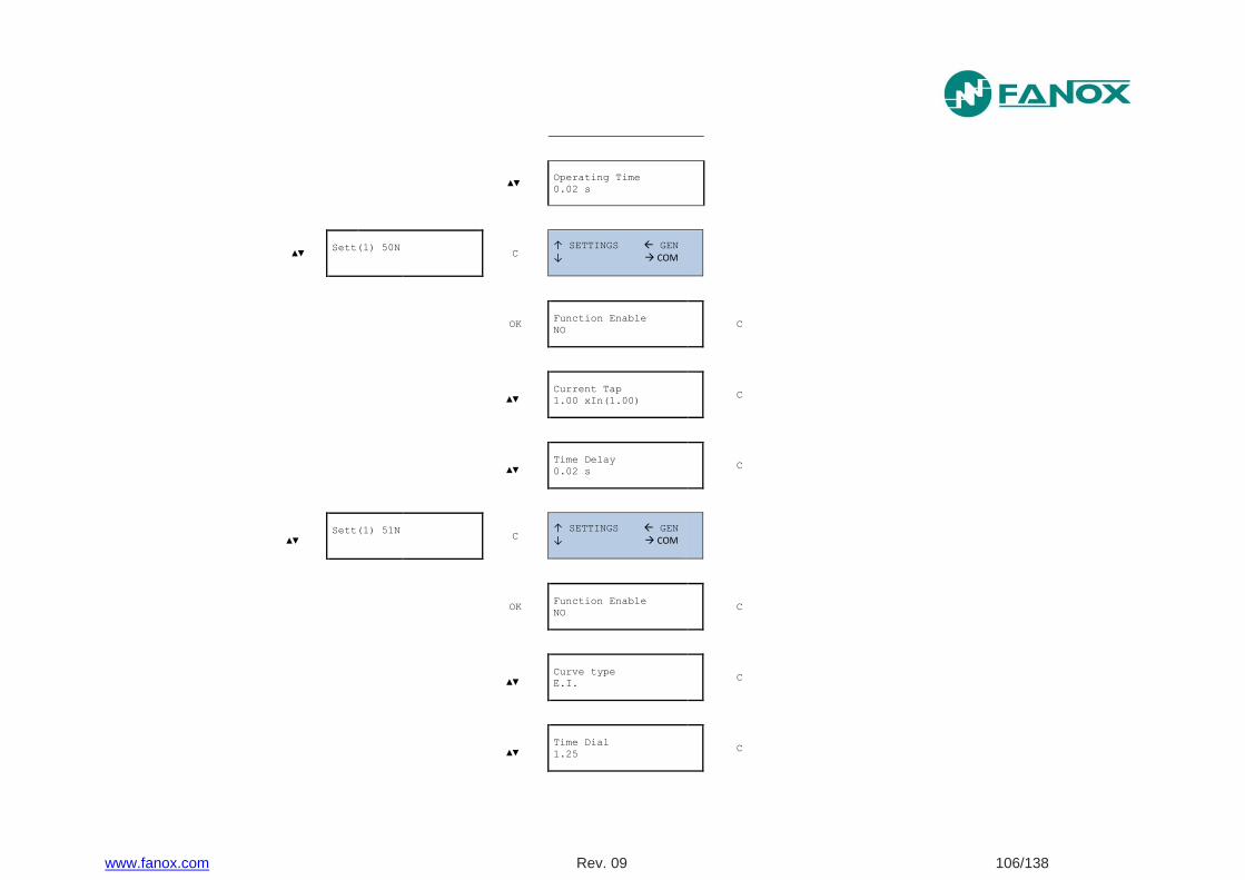
www.fanox.com Rev. 09 106/138
▲▼ Operating Time
0.02 s
▲▼ Sett(1) 50N
C
↑ SETTINGS GEN
↓ COM
OK Function Enable
NO C
▲▼
Current Tap
1.00 xIn(1.00) C
▲▼
Time Delay
0.02 s C
▲▼
▲▼ Sett(1) 51N
C
↑ SETTINGS GEN
↓ COM
OK Function Enable
NO C
▲▼
Curve type
E.I. C
▲▼
Time Dial
1.25 C
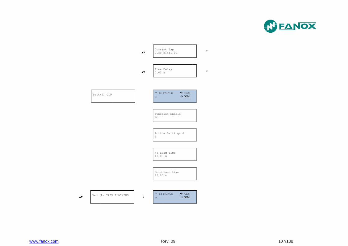
www.fanox.com Rev. 09 107/138
▲▼
Current Tap
0.50 xIn(1.00) C
▲▼
Time Delay
0.02 s C
Sett(1) CLP
↑ SETTINGS GEN
↓ COM
Function Enable
No
Active Settings G.
3
No Load Time
15.00 s
Cold Load time
15.00 s
▲▼ Sett(1) TRIP BLOCKING
C
↑ SETTINGS GEN
↓ COM
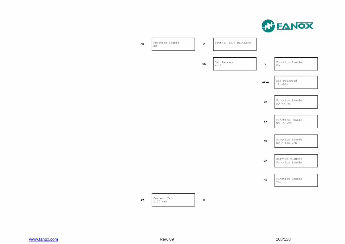
www.fanox.com Rev. 09 108/138
OK Function Enable
NO C
Sett(1) TRIP BLOCKING
OK
Set Password
-> 0 C
Function Enable
NO
◄▼▲► Set Password
-> 5555
OK Function Enable
NO -> NO
▲▼ Function Enable
NO -> YES
OK Function Enable
NO > YES y/n
OK SETTING CHANGED
Function Enable
OK Function Enable
YES
▲▼ Current Tap
1.00 xIn C

www.fanox.com Rev. 09 109/138
▲▼ Sett(1) 49
C
↑ SETTINGS GEN
↓ COM
OK Function Enable
NO C
Sett(1) 49
▲▼ Current Tap
0.20 xIn C
▲▼ Heating Constant
3 min C
▲▼ Cooling constant
3x heating constant C
▲▼ Alarm
80 C
▲▼ Sett(1) 50BF
C
↑ SETTINGS GEN
↓ COM
OK Function Enable
NO C
Sett(1) 50BF
▲▼ Time Delay
0,02 s C
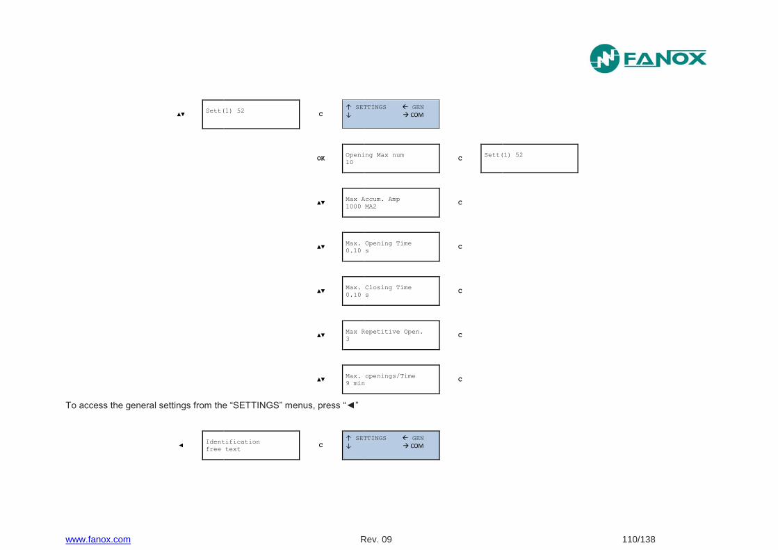
www.fanox.com Rev. 09 110/138
▲▼ Sett(1) 52
C
↑ SETTINGS GEN
↓ COM
OK Opening Max num
10 C
Sett(1) 52
▲▼ Max Accum. Amp
1000 MA2 C
▲▼ Max. Opening Time
0.10 s C
▲▼ Max. Closing Time
0.10 s C
▲▼ Max Repetitive Open.
3 C
▲▼ Max. openings/Time
9 min C
To access the general settings from the “SETTINGS” menus, press “◄”
◄ Identification
free text C
↑ SETTINGS GEN
↓ COM
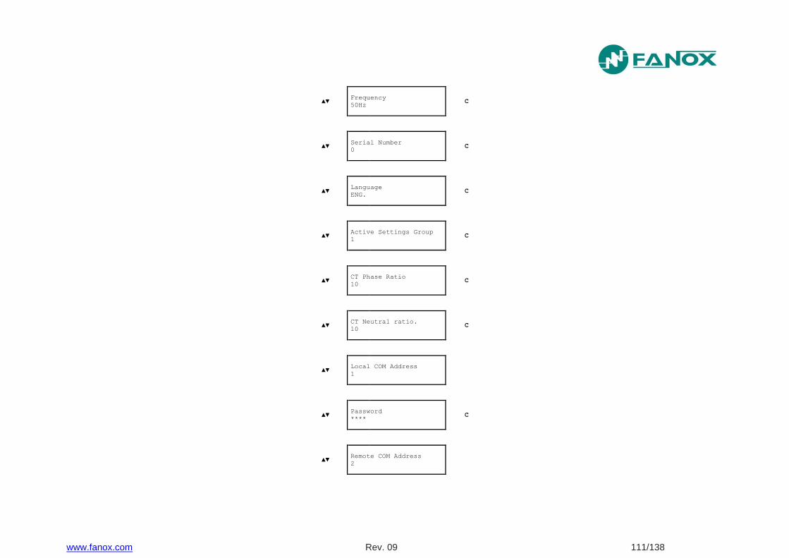
www.fanox.com Rev. 09 111/138
▲▼ Frequency
50Hz C
▲▼ Serial Number
0 C
▲▼ Language
ENG. C
▲▼ Active Settings Group
1 C
▲▼ CT Phase Ratio
10 C
▲▼ CT Neutral ratio.
10 C
▲▼
Local COM Address
1
▲▼ Password
**** C
▲▼
Remote COM Address
2

www.fanox.com Rev. 09 112/138
7.7.11. Events Menu
From the standby mode screen, press the “OK” key to access the first line of menus. Use the “▲” and “▼” keys to position the cursor over the “EVENTS” screen and the number of events in the buffer will be displayed. Press "OK" and use the “▲” and “▼” keys to position the cursor over the events.
↑
↓
EVENTS
There are 5 C
SIAF110AC110AA
0.00 0.00 0.00 0.00
OK 12/04/12 01:57:03260
┘ Eeprom changed C
↑
↓
EVENTS
There are 5
▲▼ 12/04/12 01:57:03180
┐ 52 Open Error OK
4/5: 0
┐ 52 Open Error C
RESET Set Password
-> 0 C
↑
↓
EVENTS
There are 5
◄▼▲► Set Password
-> 5555 C
OK Confirm
Erased Events y/n? C
OK ↑
↓
EVENTS
There are 1 C
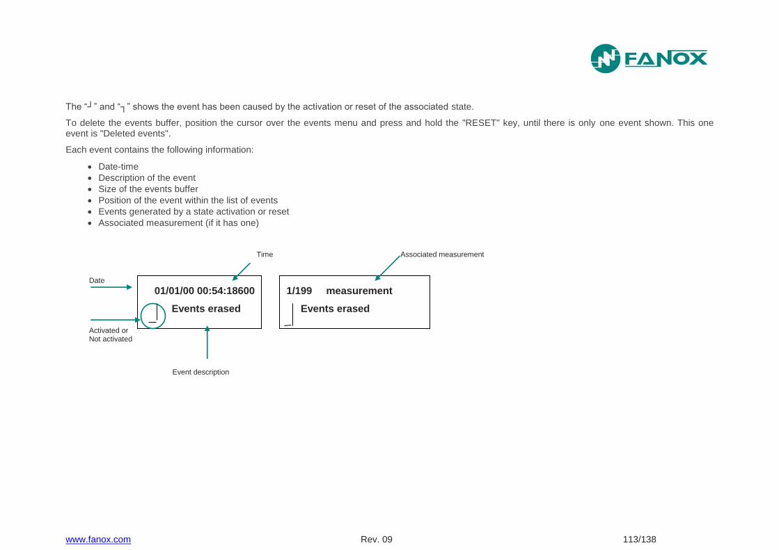
www.fanox.com Rev. 09 113/138
The “┘” and “┐” shows the event has been caused by the activation or reset of the associated state.
To delete the events buffer, position the cursor over the events menu and press and hold the "RESET" key, until there is only one event shown. This one event is "Deleted events".
Each event contains the following information:
Date-time
Description of the event
Size of the events buffer
Position of the event within the list of events
Events generated by a state activation or reset
Associated measurement (if it has one)
Date
Event description
Activated or Not activated
01/01/00 00:54:18600
Events erased
1/199 measurement
Events erased
Associated measurement
Time
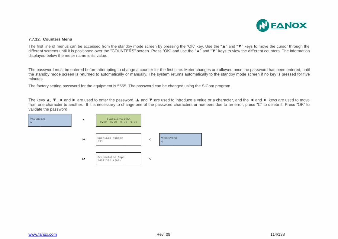
www.fanox.com Rev. 09 114/138
7.7.12. Counters Menu
The first line of menus can be accessed from the standby mode screen by pressing the “OK” key. Use the “▲” and “▼” keys to move the cursor through the different screens until it is positioned over the "COUNTERS" screen. Press "OK" and use the “▲” and “▼” keys to view the different counters. The information displayed below the meter name is its value.
The password must be entered before attempting to change a counter for the first time. Meter changes are allowed once the password has been entered, until the standby mode screen is returned to automatically or manually. The system returns automatically to the standby mode screen if no key is pressed for f ive minutes.
The factory setting password for the equipment is 5555. The password can be changed using the SICom program.
The keys ▲, ▼, ◄ and ► are used to enter the password. ▲ and ▼ are used to introduce a value or a character, and the ◄ and ► keys are used to move from one character to another. If it is necessary to change one of the password characters or numbers due to an error, press "C" to delete it. Press "OK” to validate the password.
↑COUNTERS
↓ C
SIAF110AC110AA
0.00 0.00 0.00 0.00
OK Openings Number
133 C
↑COUNTERS
↓
▲▼ Accumulated Amps
14011325 k(A2) C
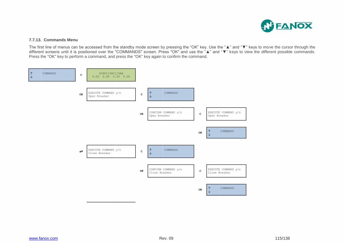
www.fanox.com Rev. 09 115/138
7.7.13. Commands Menu
The first line of menus can be accessed from the standby mode screen by pressing the “OK” key. Use the “▲” and “▼” keys to move the cursor through the different screens until it is positioned over the "COMMANDS" screen. Press "OK" and use the “▲” and “▼” keys to view the different possible commands. Press the "OK" key to perform a command, and press the "OK" key again to confirm the command.
↑
↓
COMMANDS
C
SIAF110AC110AA
0.00 0.00 0.00 0.00
OK EXECUTE COMMAND y/n
Open Breaker C
↑
↓
COMMANDS
OK CONFIRM COMMAND y/n
Open Breaker C
EXECUTE COMMAND y/n
Open Breaker
OK ↑
↓
COMMANDS
▲▼ EXECUTE COMMAND y/n
Close Breaker C
↑
↓
COMMANDS
OK CONFIRM COMMAND y/n
Close Breaker C
EXECUTE COMMAND y/n
Close Breaker
OK ↑
↓
COMMANDS
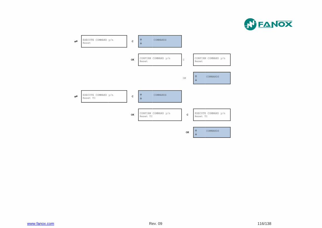
www.fanox.com Rev. 09 116/138
▲▼ EXECUTE COMMAND y/n
Reset C
↑
↓
COMMANDS
OK CONFIRM COMMAND y/n
Reset C
CONFIRM COMMAND y/n
Reset
OK ↑
↓
COMMANDS
▲▼ EXECUTE COMMAND y/n
Reset TI C
↑
↓
COMMANDS
OK CONFIRM COMMAND y/n
Reset TI C
EXECUTE COMMAND y/n
Reset TI
OK ↑
↓
COMMANDS
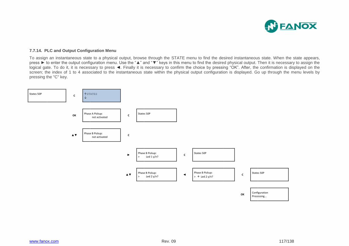
www.fanox.com Rev. 09 117/138
7.7.14. PLC and Output Configuration Menu
To assign an instantaneous state to a physical output, browse through the STATE menu to find the desired instantaneous state. When the state appears, press ► to enter the output configuration menu. Use the “▲” and “▼” keys in this menu to find the desired physical output. Then it is necessary to assign the logical gate. To do it, it is necessary to press ◄. Finally it is necessary to confirm the choice by pressing “OK”. After, the confirmation is displayed on the screen; the index of 1 to 4 associated to the instantaneous state within the physical output configuration is displayed. Go up through the menu levels by pressing the "C" key.
States 50P
C ↑STATES
↓
OK Phase A Pickup: not activated
C States 50P
▲▼ Phase B Pickup: not activated
C
►
Phase B Pickup: > Led 1 y/n?
C States 50P
▲▼
Phase B Pickup: > Led 2 y/n?
◄ Phase B Pickup:
> + Led 2 y/n? C
States 50P
OK Configuration Processing...
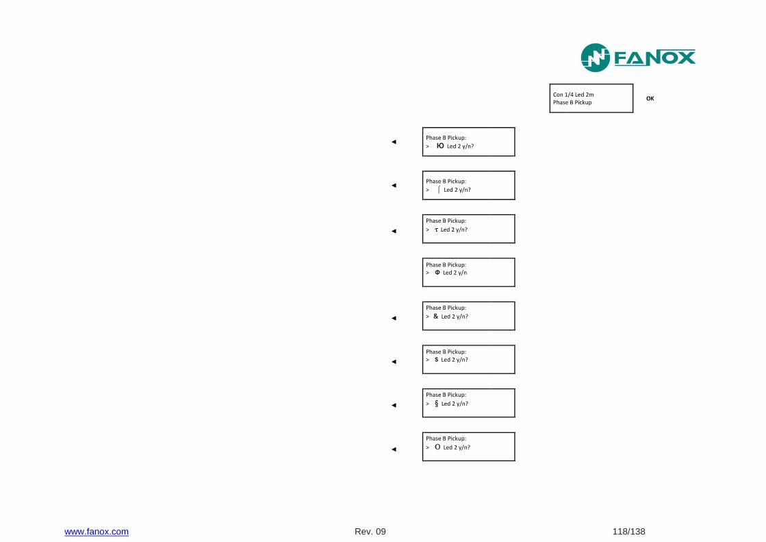
www.fanox.com Rev. 09 118/138
Con 1/4 Led 2m Phase B Pickup
OK
◄
Phase B Pickup:
> Ю Led 2 y/n?
◄
Phase B Pickup:
> ⌠ Led 2 y/n?
◄
Phase B Pickup:
> Led 2 y/n?
Phase B Pickup: > Φ Led 2 y/n
◄
Phase B Pickup:
> & Led 2 y/n?
◄
Phase B Pickup: > $ Led 2 y/n?
◄
Phase B Pickup:
> § Led 2 y/n?
◄
Phase B Pickup:
> O Led 2 y/n?
www.fanox.com Rev. 09 119/138
◄
Phase B Pickup:
> P Led 2 y/n?
◄
Phase B Pickup:
> Q Led 2 y/n?
◄
Phase B Pickup:
> R Led 2 y/n?
◄
Phase B Pickup:
> o Led 2 y/n?
◄
Phase B Pickup:
> p Led 2 y/n?
◄
Phase B Pickup:
> q Led 2 y/n?
◄
Phase B Pickup:
> r Led 2 y/n?
▲▼
Phase B Pickup: > Led 3 y/n?
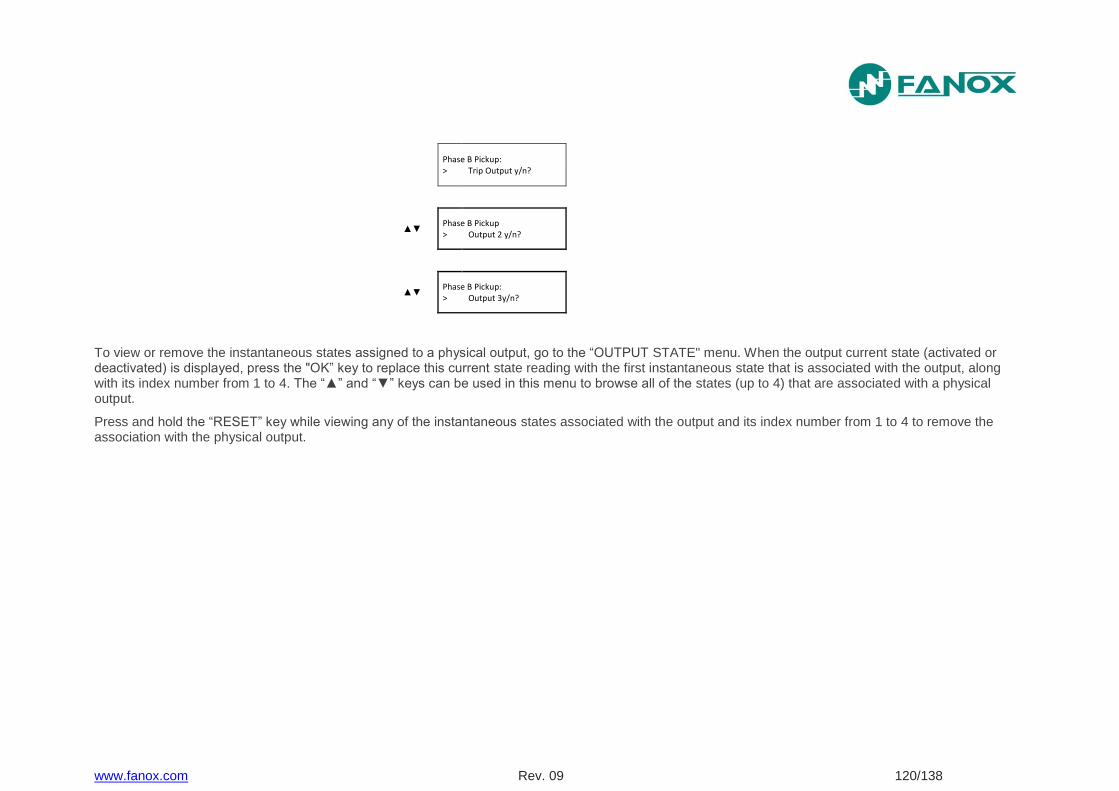
www.fanox.com Rev. 09 120/138
Phase B Pickup:
> Trip Output y/n?
▲▼
Phase B Pickup > Output 2 y/n?
▲▼
Phase B Pickup: > Output 3y/n?
To view or remove the instantaneous states assigned to a physical output, go to the “OUTPUT STATE" menu. When the output current state (activated or deactivated) is displayed, press the "OK” key to replace this current state reading with the first instantaneous state that is associated with the output, along with its index number from 1 to 4. The “▲” and “▼” keys can be used in this menu to browse all of the states (up to 4) that are associated with a physical output.
Press and hold the “RESET” key while viewing any of the instantaneous states associated with the output and its index number from 1 to 4 to remove the association with the physical output.
www.fanox.com Rev. 10 121/138
8. MODBUS RTU PROTOCOL
This document describes the steps to follow to read and write data on the SIA-F relay, as per the ModBus/RTU protocol. This memory map is only valid for one piece of equipment and one version of the memory. The positions of existing objects in the memory remain fixed from one version to the next, but new objects will naturally have new addresses which will, in turn, remain fixed in future versions. The memory map is described further on.
The standard ModBus/RTU protocol is used, so any program or PC can communicate easily with the equipment.
The SIA-F always acts as a slave, which means that it never initiates communications. The master is always responsible for initiating communications.
Only a subset of the ModBus/RTU functions is implemented:
Reading function 3.
Writing function 16.
The ModBus/RTU protocol is independent from the hardware. Therefore, the physical layer can exist in different hardware configurations: RS232, RS485, fiber optic or Ethernet.
Specifically, the relay has a front RS232 port and, as an option, a rear RS485 port. The data stream in any of the configurations is “half-duplex”.
Each byte of data is transmitted asynchronously and is made up of: 1 start bit, 8 data bits, 1 stop bit and 1 parity bit, if this is how it is programmed. Therefore, the data has 10 or 11 bits, depending on whether or not it includes parity.
When the equipment has a single front port, the address can be configured but the rest of the parameters are fixed: the speed is 19200, without parity and with 1 stop bit.
If the equipment is fitted with two switched ports, one front and one rear, the following features can be configured: speed (1200, 2400, 4800, 9600 or 19200), parity (even, odd or no parity), the stop bits (1 or 2) and the address (1 to 247).
The master must know the address of the slave that it is going to communicate with. No unit will act on requests from the master if the message is not addressed to them. The exception is when the 0 address, or “broadcast” address, is used, in which case the relay will act but will not send an answer of any type.
Communications are made in packages or frames, which are groups of data that are sent asynchronously. The master transmits a frame to the slave, and the slave then replies with another frame (except in the case of “broadcast” messages).
The end of the frame is marked by a dead time or silence time in the communication medium. The length of this time of silence varies depending on the transmission speed, as it is equivalent to 3 characters.
The following table shows the generic package format that is valid for transmission and reception. However, each function has its own peculiarities, as will be described further on.
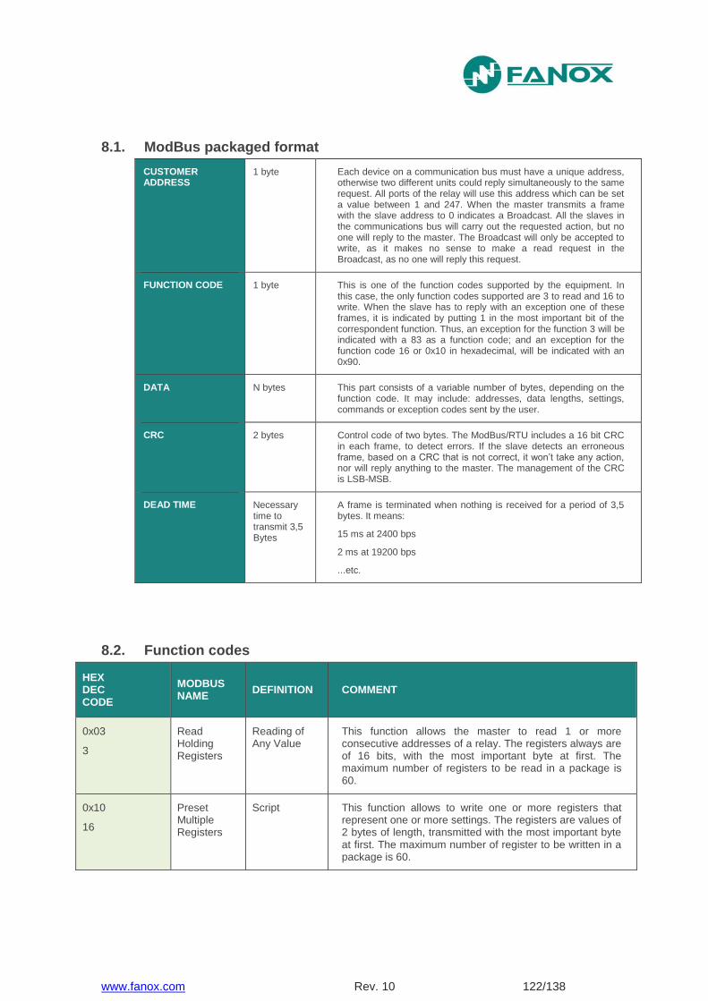
www.fanox.com Rev. 10 122/138
8.1. ModBus packaged format
CUSTOMER ADDRESS
1 byte Each device on a communication bus must have a unique address, otherwise two different units could reply simultaneously to the same request. All ports of the relay will use this address which can be set a value between 1 and 247. When the master transmits a frame with the slave address to 0 indicates a Broadcast. All the slaves in the communications bus will carry out the requested action, but no one will reply to the master. The Broadcast will only be accepted to write, as it makes no sense to make a read request in the Broadcast, as no one will reply this request.
FUNCTION CODE 1 byte This is one of the function codes supported by the equipment. In this case, the only function codes supported are 3 to read and 16 to write. When the slave has to reply with an exception one of these frames, it is indicated by putting 1 in the most important bit of the correspondent function. Thus, an exception for the function 3 will be indicated with a 83 as a function code; and an exception for the function code 16 or 0x10 in hexadecimal, will be indicated with an 0x90.
DATA N bytes This part consists of a variable number of bytes, depending on the function code. It may include: addresses, data lengths, settings, commands or exception codes sent by the user.
CRC 2 bytes Control code of two bytes. The ModBus/RTU includes a 16 bit CRC in each frame, to detect errors. If the slave detects an erroneous frame, based on a CRC that is not correct, it won’t take any action, nor will reply anything to the master. The management of the CRC is LSB-MSB.
DEAD TIME Necessary time to transmit 3,5 Bytes
A frame is terminated when nothing is received for a period of 3,5 bytes. It means:
15 ms at 2400 bps
2 ms at 19200 bps
...etc.
8.2. Function codes
HEX DEC CODE
MODBUS NAME
DEFINITION COMMENT
0x03
3
Read Holding Registers
Reading of Any Value
This function allows the master to read 1 or more consecutive addresses of a relay. The registers always are of 16 bits, with the most important byte at first. The maximum number of registers to be read in a package is 60.
0x10
16
Preset Multiple Registers
Script This function allows to write one or more registers that represent one or more settings. The registers are values of 2 bytes of length, transmitted with the most important byte at first. The maximum number of register to be written in a package is 60.
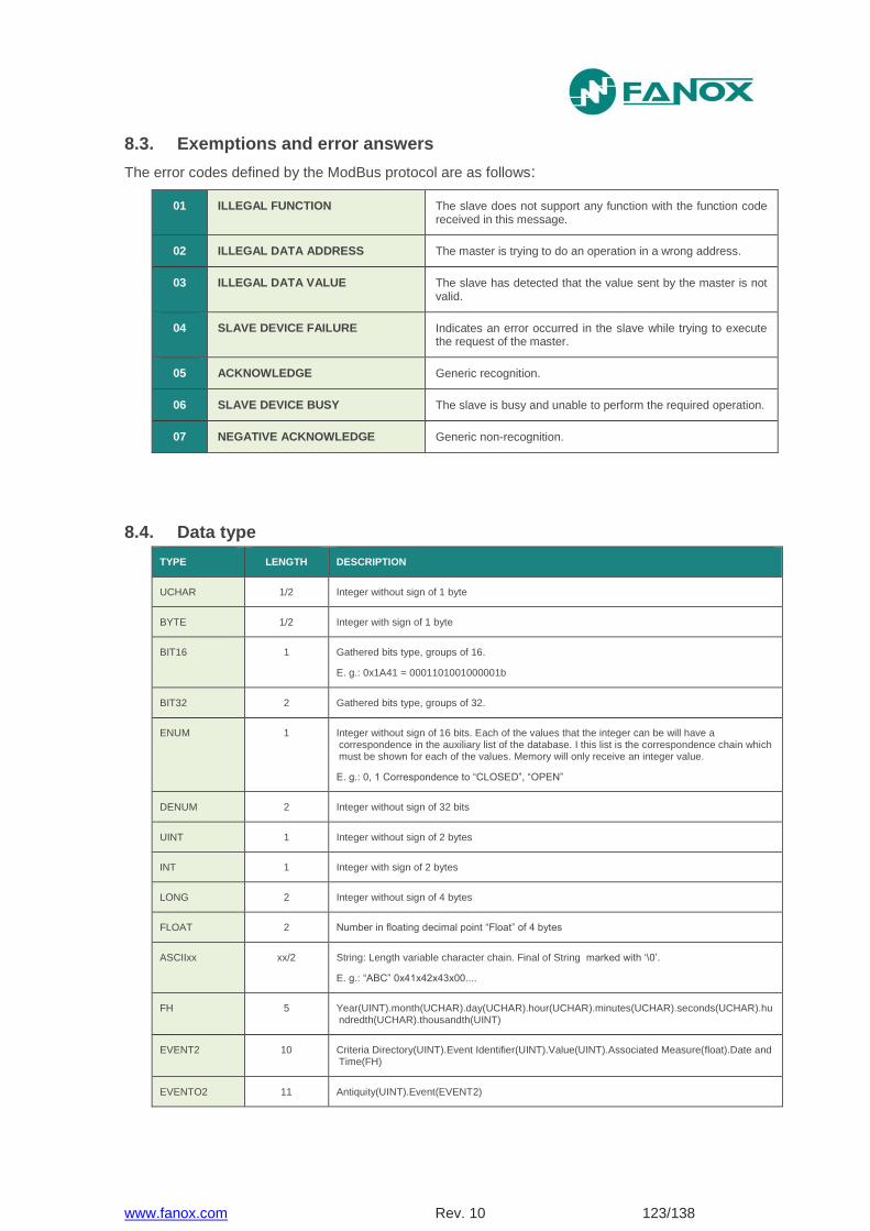
www.fanox.com Rev. 10 123/138
8.3. Exemptions and error answers
The error codes defined by the ModBus protocol are as follows:
01 ILLEGAL FUNCTION The slave does not support any function with the function code received in this message.
02 ILLEGAL DATA ADDRESS The master is trying to do an operation in a wrong address.
03 ILLEGAL DATA VALUE The slave has detected that the value sent by the master is not valid.
04 SLAVE DEVICE FAILURE Indicates an error occurred in the slave while trying to execute the request of the master.
05 ACKNOWLEDGE Generic recognition.
06 SLAVE DEVICE BUSY The slave is busy and unable to perform the required operation.
07 NEGATIVE ACKNOWLEDGE Generic non-recognition.
8.4. Data type
TYPE LENGTH DESCRIPTION
UCHAR 1/2 Integer without sign of 1 byte
BYTE 1/2 Integer with sign of 1 byte
BIT16 1 Gathered bits type, groups of 16.
E. g.: 0x1A41 = 0001101001000001b
BIT32 2 Gathered bits type, groups of 32.
ENUM 1 Integer without sign of 16 bits. Each of the values that the integer can be will have a correspondence in the auxiliary list of the database. I this list is the correspondence chain which must be shown for each of the values. Memory will only receive an integer value.
E. g.: 0, 1 Correspondence to “CLOSED”, “OPEN”
DENUM 2 Integer without sign of 32 bits
UINT 1 Integer without sign of 2 bytes
INT 1 Integer with sign of 2 bytes
LONG 2 Integer without sign of 4 bytes
FLOAT 2 Number in floating decimal point “Float” of 4 bytes
ASCIIxx xx/2 String: Length variable character chain. Final of String marked with ‘\0’.
E. g.: “ABC” 0x41x42x43x00....
FH 5 Year(UINT).month(UCHAR).day(UCHAR).hour(UCHAR).minutes(UCHAR).seconds(UCHAR).hundredth(UCHAR).thousandth(UINT)
EVENT2 10 Criteria Directory(UINT).Event Identifier(UINT).Value(UINT).Associated Measure(float).Date and Time(FH)
EVENTO2 11 Antiquity(UINT).Event(EVENT2)
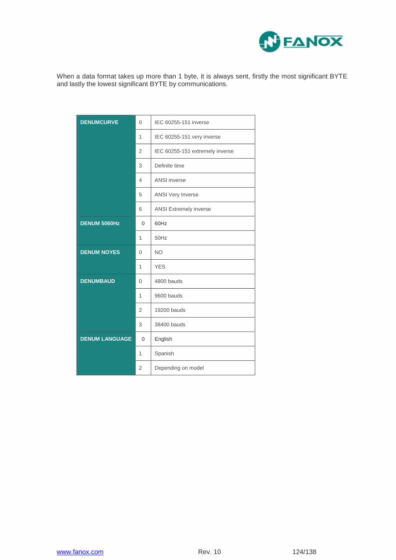
www.fanox.com Rev. 10 124/138
When a data format takes up more than 1 byte, it is always sent, firstly the most significant BYTE and lastly the lowest significant BYTE by communications.
DENUMCURVE 0 IEC 60255-151 inverse
1 IEC 60255-151 very inverse
2 IEC 60255-151 extremely inverse
3 Definite time
4 ANSI inverse
5 ANSI Very Inverse
6 ANSI Extremely inverse
DENUM 5060Hz 0 60Hz
1 50Hz
DENUM NOYES 0 NO
1 YES
DENUMBAUD 0 4800 bauds
1 9600 bauds
2 19200 bauds
3 38400 bauds
DENUM LANGUAGE 0 English
1 Spanish
2 Depending on model
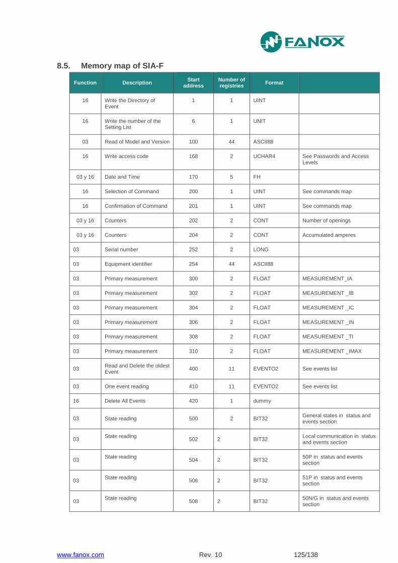
www.fanox.com Rev. 10 125/138
8.5. Memory map of SIA-F
Function Description Start
address Number of registries
Format
16 Write the Directory of Event
1 1 UINT
16 Write the number of the Setting List
6 1 UNIT
03 Read of Model and Version 100 44 ASCII88
16 Write access code 168 2 UCHAR4 See Passwords and Access Levels
03 y 16 Date and Time 170 5 FH
16 Selection of Command 200 1 UINT See commands map
16 Confirmation of Command 201 1 UINT See commands map
03 y 16 Counters 202 2 CONT Number of openings
03 y 16 Counters 204 2 CONT Accumulated amperes
03 Serial number 252 2 LONG
03 Equipment identifier 254 44 ASCII88
03 Primary measurement 300 2 FLOAT MEASUREMENT_IA
03 Primary measurement 302 2 FLOAT MEASUREMENT _IB
03 Primary measurement 304 2 FLOAT MEASUREMENT _IC
03 Primary measurement 306 2 FLOAT MEASUREMENT _IN
03 Primary measurement 308 2 FLOAT MEASUREMENT _TI
03 Primary measurement 310 2 FLOAT MEASUREMENT _IMAX
03 Read and Delete the oldest Event
400 11 EVENTO2 See events list
03 One event reading 410 11 EVENTO2 See events list
16 Delete All Events 420 1 dummy
03 State reading 500 2 BIT32 General states in status and events section
03 State reading
502 2 BIT32 Local communication in status and events section
03 State reading
504 2 BIT32 50P in status and events section
03 State reading
506 2 BIT32 51P in status and events section
03 State reading
508 2 BIT32 50N/G in status and events section
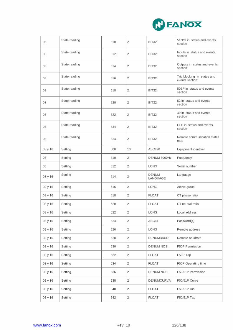
www.fanox.com Rev. 10 126/138
03 State reading
510 2 BIT32 51N/G in status and events section
03 State reading
512 2 BIT32 Inputs in status and events section
03 State reading
514 2 BIT32 Outputs in status and events sectionº
03 State reading
516 2 BIT32 Trip blocking in status and events sectionº
03 State reading
518 2 BIT32 50BF in status and events section
03 State reading
520 2 BIT32 52 in status and events section
03 State reading
522 2 BIT32 49 in status and events section
03 State reading
534 2 BIT32 CLP in status and events section
03 State reading
524 2 BIT32 Remote communication states map
03 y 16 Setting 600 10 ASCII20 Equipment identifier
03 Setting 610 2 DENUM 5060Hz Frequency
03 Setting 612 2 LONG Serial number
03 y 16 Setting
614 2 DENUM LANGUAGE
Language
03 y 16 Setting 616 2 LONG Active group
03 y 16 Setting 618 2 FLOAT CT phase ratio
03 y 16 Setting 620 2 FLOAT CT neutral ratio
03 y 16 Setting 622 2 LONG Local address
03 y 16 Setting 624 2 ASCII4 Password[4]
03 y 16 Setting 626 2 LONG Remote address
03 y 16 Setting 628 2 DENUMBAUD Remote baudrate
03 y 16 Setting 630 2 DENUM NOSI F50P Permission
03 y 16 Setting 632 2 FLOAT F50P Tap
03 y 16 Setting 634 2 FLOAT F50P Operating time
03 y 16 Setting 636 2 DENUM NOSI F50/51P Permission
03 y 16 Setting 638 2 DENUMCURVA F50/51P Curve
03 y 16 Setting 640 2 FLOAT F50/51P Dial
03 y 16 Setting 642 2 FLOAT F50/51P Tap
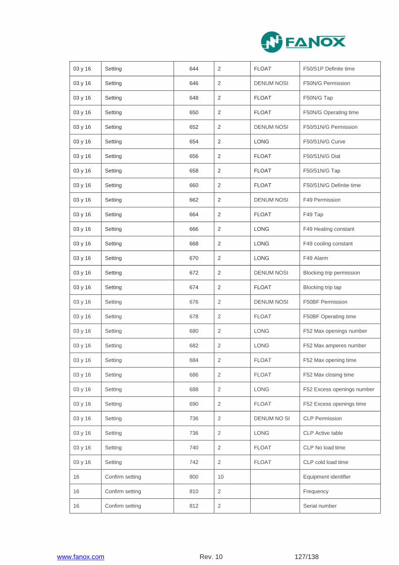
www.fanox.com Rev. 10 127/138
03 y 16 Setting 644 2 FLOAT F50/51P Definite time
03 y 16 Setting 646 2 DENUM NOSI F50N/G Permission
03 y 16 Setting 648 2 FLOAT F50N/G Tap
03 y 16 Setting 650 2 FLOAT F50N/G Operating time
03 y 16 Setting 652 2 DENUM NOSI F50/51N/G Permission
03 y 16 Setting 654 2 LONG F50/51N/G Curve
03 y 16 Setting 656 2 FLOAT F50/51N/G Dial
03 y 16 Setting 658 2 FLOAT F50/51N/G Tap
03 y 16 Setting 660 2 FLOAT F50/51N/G Definite time
03 y 16 Setting 662 2 DENUM NOSI F49 Permission
03 y 16 Setting 664 2 FLOAT F49 Tap
03 y 16 Setting 666 2 LONG F49 Heating constant
03 y 16 Setting 668 2 LONG F49 cooling constant
03 y 16 Setting 670 2 LONG F49 Alarm
03 y 16 Setting 672 2 DENUM NOSI Blocking trip permission
03 y 16 Setting 674 2 FLOAT Blocking trip tap
03 y 16 Setting 676 2 DENUM NOSI F50BF Permission
03 y 16 Setting 678 2 FLOAT F50BF Operating time
03 y 16 Setting 680 2 LONG F52 Max openings number
03 y 16 Setting 682 2 LONG F52 Max amperes number
03 y 16 Setting 684 2 FLOAT F52 Max opening time
03 y 16 Setting 686 2 FLOAT F52 Max closing time
03 y 16 Setting 688 2 LONG F52 Excess openings number
03 y 16 Setting 690 2 FLOAT F52 Excess openings time
03 y 16 Setting 736 2 DENUM NO SI CLP Permission
03 y 16 Setting 736 2 LONG CLP Active table
03 y 16 Setting 740 2 FLOAT CLP No load time
03 y 16 Setting 742 2 FLOAT CLP cold load time
16 Confirm setting 800 10 Equipment identifier
16 Confirm setting 810 2 Frequency
16 Confirm setting 812 2 Serial number
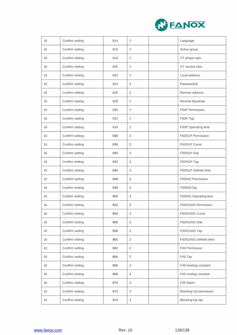
www.fanox.com Rev. 10 128/138
16 Confirm setting 814 2 Language
16 Confirm setting 816 2 Active group
16 Confirm setting 818 2 CT phase ratio
16 Confirm setting 820 2 CT neutral ratio
16 Confirm setting 822 2 Local address
16 Confirm setting 824 2 Password[4]
16 Confirm setting 826 2 Remote address
16 Confirm setting 828 2 Remote Baudrate
16 Confirm setting 830 2 F50P Permission
16 Confirm setting 832 2 F50P Tap
16 Confirm setting 834 2 F50P Operating time
16 Confirm setting 836 2 F50/51P Permission
16 Confirm setting 838 2 F50/51P Curve
16 Confirm setting 840 2 F50/51P Dial
16 Confirm setting 842 2 F50/51P Tap
16 Confirm setting 844 2 F50/51P Definite time
16 Confirm setting 846 2 F50N/G Permission
16 Confirm setting 848 2 F50N/GTap
16 Confirm setting 850 2 F50N/G Operating time
16 Confirm setting 852 2 F50/51N/G Permission
16 Confirm setting 854 2 F50/51N/G Curve
16 Confirm setting 856 2 F50/51N/G Dial
16 Confirm setting 858 2 F50/51N/G Tap
16 Confirm setting 860 2 F50/51N/G Definite time
16 Confirm setting 862 2 F49 Permission
16 Confirm setting 864 2 F49 Tap
16 Confirm setting 866 2 F49 Heating constant
16 Confirm setting 868 2 F49 cooling constant
16 Confirm setting 870 2 F49 Alarm
16 Confirm setting 872 2 Blocking trip permission
16 Confirm setting 874 2 Blocking trip tap
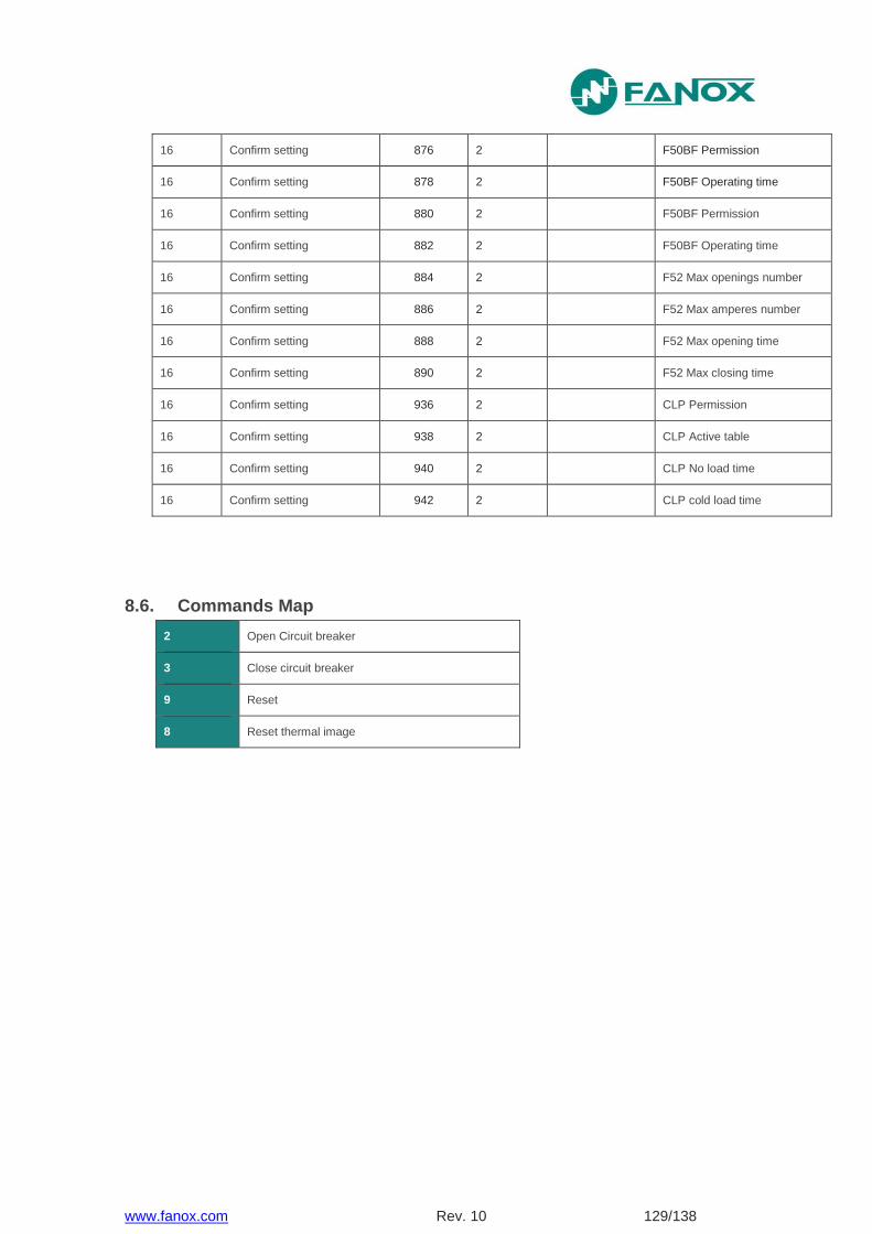
www.fanox.com Rev. 10 129/138
16 Confirm setting 876 2 F50BF Permission
16 Confirm setting 878 2 F50BF Operating time
16 Confirm setting 880 2 F50BF Permission
16 Confirm setting 882 2 F50BF Operating time
16 Confirm setting 884 2 F52 Max openings number
16 Confirm setting 886 2 F52 Max amperes number
16 Confirm setting 888 2 F52 Max opening time
16 Confirm setting 890 2 F52 Max closing time
16 Confirm setting 936 2 CLP Permission
16 Confirm setting 938 2 CLP Active table
16 Confirm setting 940 2 CLP No load time
16 Confirm setting 942 2 CLP cold load time
8.6. Commands Map
2 Open Circuit breaker
3 Close circuit breaker
9 Reset
8 Reset thermal image
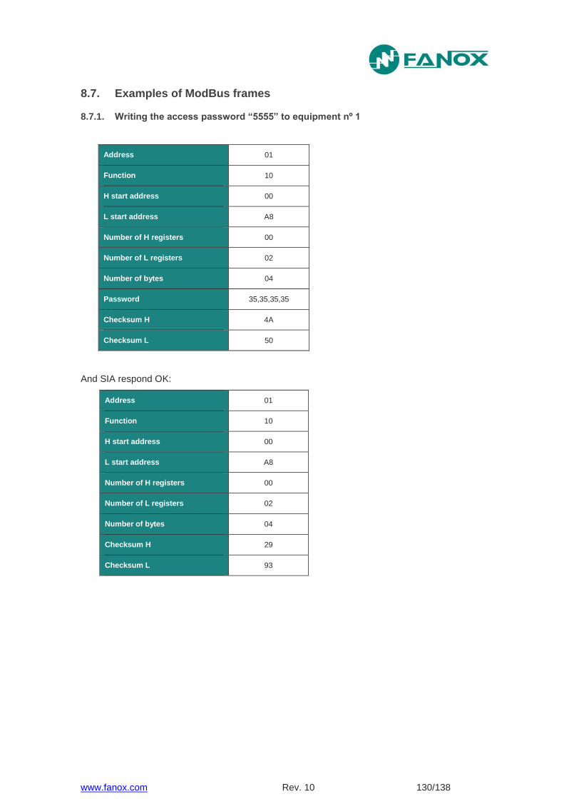
www.fanox.com Rev. 10 130/138
8.7. Examples of ModBus frames
8.7.1. Writing the access password “5555” to equipment nº 1
Address 01
Function 10
H start address 00
L start address A8
Number of H registers 00
Number of L registers 02
Number of bytes 04
Password 35,35,35,35
Checksum H 4A
Checksum L 50
And SIA respond OK:
Address 01
Function 10
H start address 00
L start address A8
Number of H registers 00
Number of L registers 02
Number of bytes 04
Checksum H 29
Checksum L 93

www.fanox.com Rev. 10 131/138
9. COMMISSIONING
9.1. Checklist for Commissioning
The commissioning sheets that are needed to register the commissioning process and the specific
settings for each installed piece of equipment are found in the Appendix.
9.2. Electrostatic discharge
Before handling any of the equipment electronic components, make sure that you have read the section of the user manual related to electrostatic discharges.
9.3. Visual Inspection
Make sure that the cabling has been installed as per the external connection diagrams.
9.4. Earthing
It is very important for the equipment to be earthed correctly. To check this, make sure that the equipment earth connection, located on the reverse side of the relay, is correctly connected to the facility local earth connection.
9.5. Current transformers
The high voltage that is generated in the secondary circuits of current transformers can cause death and could damage the facility. Therefore, the secondary circuits of current transformers should never be opened.
9.6. Auxiliary power
If an SIA-F relay with auxiliary power is required, this must be specified on the order reference. The amount of auxiliary power required for the SIA-F relay should be checked: 110-230 Vac 50/60 Hz or 90-300 Vdc or 24-48 Vdc.
9.7. Front communications port
To perform this test, connect a PC with the SICom software program to the SIA-F relay, and check that there are no communication errors. It is important to check communications port (COM) which is assign to USB.

www.fanox.com Rev. 10 132/138
9.8. Commissioning
It is recommended that the following safety measures are taken before starting up the facility for the first time, or after a trip event:
FANOX recommends the use of the KITCOM accessory with a battery in the front port. This additional energy source allows the relay to be monitored and the trip to function without the need for self-power in any breakdown situation.
Once all of the connections have been made, we recommend a check to make sure that they are correct, safe and well attached.
The "complete test" menu procedure should be applied. NOTE! See 5.10. It is important to check that the measurements are correct once the facility has been
powered up.
Maintenance: FANOX recommends a minimum of one facility inspection per year, to at least go
through the test menu and check the values of the measurements.
10. APPENDIX
10.1. Identification
Date : .....................................................................................................................................
Manager : ..............................................................................................................................
Substation : ............................................................................................................................
Circuit : ...................................................................................................................................
Model : ...................................................................................................................................
Serial no. : .............................................................................................................................
Software Versions : ...............................................................................................................
Model: ..................................................................................................................................
www.fanox.com Rev. 10 133/138
10.2. Checks
Cabling check:
Box earth:
Vaux value:
10.3. Test menu
Led 1: Trip Output
Led 2: Output 2:
Led 3: Output 3:
10.4. Register of commissioning settings
Password: ……………………………………………………………………………
Identification: …………………………………………………………………………
CT Ratio
Phase CT Ratio: ……………………..........…………………………………………………….
Neutral CT Ratio: ……………………..........……………………………………………………
50P
Permission Enabled Disabled
Tap.........................…………… x In
Operating Time: ..........………... s
50N/G
Permission Enabled Disabled
Tap.........................…………… x In
Operating Time: .........………... s
50/51P
Permission Enabled Disabled
Tap.........................…………… x In
IEC curve Inverse Very Inverse Extrem. Inverse Definite time
Dial ...........………………
Operating Time ……………… s
www.fanox.com Rev. 10 134/138
50/51N/G
Permission Enabled Disabled
Tap....................……………… x In
IEC curve Inverse Very Inverse Extrem. Inverse Definite time
Dial……...................…………….
Operating Time…..…..……. s
CLP
Permission Enabled Disabled
Active table Table 1 Table 2 Table 3
No load time……………………… s
Cold load time…………………… s
49
Permission Enabled Disabled
Tap……..………………………… x In
ζ heating: …………………………. min
ζ cooling: …………………………. ζ heating
Alarm: …………………………… %
50BF
Permission Enabled Disabled
Operating time ……..… s
Trip blocking
Permission Enabled Disabled
Blocking level.............………… x In
Circuit breaker
Excessive number of openings …............................................................................…………
Excessive accumulated amps…..............................................................................…………
Opening time….......................................................................................................…………
Closing time….....................................................................................................…………...
Excessive repeated openings ………..........................................................…………………..
Time of repeated openings …................................................................................…………
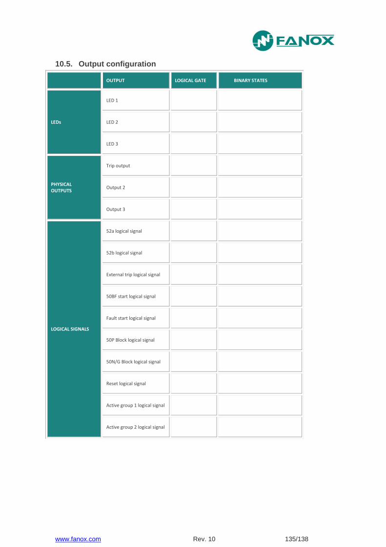
www.fanox.com Rev. 10 135/138
10.5. Output configuration
OUTPUT LOGICAL GATE BINARY STATES
LEDs
LED 1
LED 2
LED 3
PHYSICAL OUTPUTS
Trip output
Output 2
Output 3
LOGICAL SIGNALS
52a logical signal
52b logical signal
External trip logical signal
50BF start logical signal
Fault start logical signal
50P Block logical signal
50N/G Block logical signal
Reset logical signal
Active group 1 logical signal
Active group 2 logical signal

www.fanox.com Rev. 10 136/138
10.6. Comments
…………….............……………………………………………………………………………....…
…………….............……………………………………………………………………………....…
……………............……………………………………………………………………………....….
…………….............……………………………………………………………………………....…
…………….............……………………………………………………………………………....…
…………….............……………………………………………………………………………....…
…………….............……………………………………………………………………………....…
…………….............……………………………………………………………………………....…
…………….............……………………………………………………………………………....…
…………….............……………………………………………………………………………....…
…………….............……………………………………………………………………………....…
…………….............……………………………………………………………………………....…
…………….............……………………………………………………………………………....…
…………….............……………………………………………………………………………....…
…………….............……………………………………………………………………………....…
…………….............……………………………………………………………………………....…
…………….............……………………………………………………………………………....…
…………….............……………………………………………………………………………....…
…………….............……………………………………………………………………………....…
…………….............……………………………………………………………………………....…
…………….............……………………………………………………………………………....…
…………….............……………………………………………………………………………....…
…………….............……………………………………………………………………………....…
…………….............……………………………………………………………………………....…
Person in charge of commissioning………........……..........…………..Date……….............…
Maintenance performed on the………………….. by ………..…………………………………..

www.fanox.com Rev. 10 137/138
NOTES:
……………………………………………………………………………………………………..…
……………………………………………………………………………………………………..…
……………………………………………………………………………………………………..…
……………………………………………………………………………………………………..…
……………………………………………………………………………………………………..…
……………………………………………………………………………………………………..…
……………………………………………………………………………………………………..…
……………………………………………………………………………………………………..…
……………………………………………………………………………………………………..…
……………………………………………………………………………………………………..…
……………………………………………………………………………………………………..…
……………………………………………………………………………………………………..…
……………………………………………………………………………………………………..…
……………………………………………………………………………………………………..…
……………………………………………………………………………………………………..…
……………………………………………………………………………………………………..…
……………………………………………………………………………………………………..…
……………………………………………………………………………………………………..…
……………………………………………………………………………………………………..…
……………………………………………………………………………………………………..…
……………………………………………………………………………………………………..…
……………………………………………………………………………………………………..…
……………………………………………………………………………………………………..…
……………………………………………………………………………………………………..…
……………………………………………………………………………………………………..…
……………………………………………………………………………………………………..…