side stream treatment and advanced stabilization technologies
TRANSCRIPT

Side Stream Treatment and
Advanced Stabilization Technologies

Overall Program Agenda
Time Program Item
9:30 – 10:20 Biosolids Management / Regulatory Framework
10:20 – 10:30 Break
10:30 – 12:00 Biosolids Treatment Technologies
12:00 – 13:00 Lunch
13:00 – 13:30 Sidestream Treatment and Advanced Stabilization
13:30 – 14:30 Energy Management
14:30 Workshop Closure
2

SIDESTREAM TREATMENT
NITROGEN REMOVAL
3

Conventional nitrogen removal pathway is
energy and carbon “intensive”
4
12834-031
NO -N3
NO -N2NO -N2
25% O2
75% O2
40% BOD/COD
60% BOD/COD
Nitratation
Nitritation
Denitratation
Denitritation
NH -N3 N -gas2

• Shortcuts traditional
nitrification and
/denitrification
• Stopping at nitrite
rather than nitrate.
• Uses 25% less
oxygen (theoretical)
• Uses 40% less
carbon (theoretical)
5
There are more energy and carbon
efficient pathways for nitrogen removal.

• The most energy-efficient and low cost way to remove nitrogen
• Uses 62.5% less oxygen
• Does not require any supplemental carbon
• Utilizes annamoxbacteria
Nitritation and Deammonification is an
even more efficient N removal pathway.
6

SIDESTREAM TREATMENT
PHOSPHORUS REMOVAL
7

Uncontrolled Struvite formation after
anaerobic digestion can be a problem
8

OSTARA offers a “controlled” struvite
recovery reactor system
9

Multiform Harvest offers a competing
controlled struvite recovery reactor
10

OSTARA struvite recovery reactor system
at the Nansemond WWTP.
11

OSTARA struvite recovery reactor system
at the Nansemond WWTP.
12

Product quality can vary depending on
the struvite recovery system installed.
13
OSTARA CrystalGreen Product Multiform Harvest Product

Active learning exercise…
The two major constituents of concern in
side stream from dewatering anaerobically
digested sludge are:
1. ___________________
2. ___________________
14

Active learning exercise…
What are the five chemical elements found
in struvite:1. ___________________
2. ___________________
3. ___________________
4. ___________________
5. ___________________
15

POST-DEWATERING
TREATMENT TECHNOLOGIES
16

Composting can be utilized to achieve 40
CFR 503 “Class A” standards.
17
• Space intensive
• High odor potential
• Labor and equipment
intensive for material
handling
• Seasonal product demand
• Unique marketing and
distribution challenges
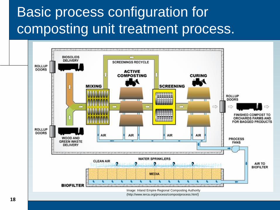
Basic process configuration for
composting unit treatment process.
18
Image: Inland Empire Regional Composting Authority
(http://www.ierca.org/process/compostprocess.html)

Alkaline stabilization can meet both
“Class A” or “Class B” standards
19
• Calcium Oxide (Lime) is
blended with dewatered
cake
• Elevated pH can result in
high ammonia odors
release
• “Class A” achieved by:
– pH + Temperature
– Time + Temperature
• Finish Product used as
Soil Conditioner

Fluid bed thermal oxidation is the current
“standard” in incineration
20Image Courtesy IDI Technologies

Thermal drying systems are “rated” by
evaporation rate capacity
21

Rotary drum thermal drying is the most
prominent technology for “large” systems.
22
Source: Andritz-Ruthner

South Cary WRF thermal drying facility
8,800 lb/hour evaporation rate capacity.
23

Compact rotary drum drying systems are
available for “smaller” size systems.
24
Photo Courtesy: Andritz-Ruthner

Belt drying systems are a more recent
addition to the sludge drying market.
25
Source: Andritz-Ruthner

Belt dryer installation in Biel, Switzerland
with an evaporation rate 2,900 lb/hour.
26
Image: Andrtiz-
Ruthner
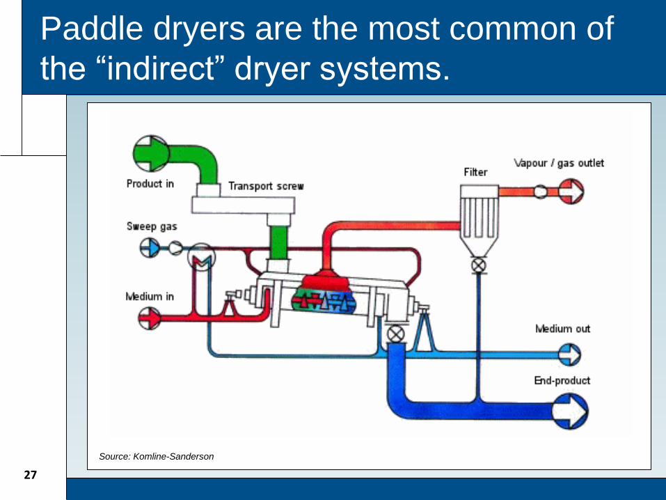
Paddle dryers are the most common of
the “indirect” dryer systems.
27
Source: Komline-Sanderson

Paddle drying system in Mason, OH with
6,500 lb/hour evaporation rate capacity.
28

Fluid bed dryers are not common in the
North American market.
29
Source: Andritz-Ruthner

Fluid bed dryer in Houthalen, Belgium
with evaporative capacity 8,000 lb/hour.
30
Image: Andritz-
Ruthner

Biosolids gasification is an emerging
technology for energy recovery.
31

Solar sludge drying beds can be covered
to reduce seasonal impacts
32
Source: Veolia-Water /
Kruger

Automation can be applied to increase
solids loading rates to reduce footprint.
33Source: Veolia-Water /
Kruger

Active learning exercise…
What are three major types of processes
used for producing a Class A biosolids after
dewatering:1. ___________________
2. ___________________
3. ___________________
34

Active learning exercise…
What is the primary criteria used for sizing
an thermal drying system?
35

Active learning exercise…
What are the five major types of thermal
drying systems on the market:1. ___________________
2. ___________________
3. ___________________
4. ___________________
5. ___________________
36

The big picture take away items…
• The “on-site” residuals stabilization and handling requirements are largely governed by the needs of the “off-site” residuals management program.
• Thickening, stabilization, dewatering, and post-dewatering treatment must work together as a system to effectively achieve residuals processing objectives.
37

Reference Materials
38

Reference Materials
39

Reference Materials
40

Questions?
C. Michael Bullard, P.E.
Vice President
National Residuals & Biosolids Leader
Hazen and Sawyer – Raleigh Office
(919) 755-8582
41

Biosolids and Residuals Processing & Energy Management Workshop
December 12, 2013
Energy Management

Agenda
• Electric Utilities Overview
• Electric Billing
• Demand Management
• Resource Recovery
• Power Monitoring
• Typical Energy Efficiency Opportunities

Energy management is more than energy
efficiency
EnergyManagement
Energy Procurement
Energy Efficiency
Resource Recovery
Demand Management
Energy Awareness
Energy Monitoring
Energy Modeling
and Planning

Energy Management has potential
savings of 10-40%
45
Biogas
Process
Optimization
Renewables
Energy Procurement

Energy Management is a Continuous
Process
46
Energy Management Program
Energy Auditing
Implement
Monitor & Verify
Education & Training

Managing energy begins with an energy
management program
Energy Modeling and Benchmarking
Power Monitoring and Plant Control Capabilities
Understand Utility Billing Rates and Configuration
Understand Current and Future Energy Costs
Demand Management
Process Optimization
Lighting
HVAC/Building
Improvements
Alternative Energy Utilization
Process Upgrades
Energy Efficient Equipment
Energy management program
High Benefit PotentialLow Capital Costs
High Benefit PotentialModerate to High Capital Costs
Moderate to Low Benefit PotentialLow Capital Costs

Electrical Utilities

United States Electric Grid
• ..

Utility Distribution Systems
Electric Utility Customers
Electric Utility
Electric Cooperative
Utility Grid

Electrical Utility Billing
“How” you are charged for
energy is just as important as
“how much” energy you use.

Utility Bill Example

Electrical utility bills are typically
comprised of several “charges”.
• Energy Usage Charge (kWh)
Energy consumed during the billing period.
Typically “Flat Rate” or “Time of Use”.
• Demand Charge (kW)
Typically 15-30 minute peak power demand during a
billing period
• Fixed Charges
Independent of demand or usage.
Facility charges
Minimum demand/energy charges

The demand profile establishes both
“demand” and “energy usage”.

Demand ratchets can significantly impact
electrical utility cost.D
eman
d (
KW
)
80% Annual Demand Ratchet Example

Demand ratchets can significantly impact
electrical utility cost.

“Time of Use” energy and demand billing
is very common

0
1
2
3
4
5
6
7
8
9
10A
vera
ge E
lect
ric
Uti
lity
Co
st ₵
/KW
H
Utility billing structures will vary
significantly
Demand Charges
Energy Charges
Fixed Charges
Plant A Plant B

Energy efficiency benefit example:
LED Lighting
• LED outdoor lighting reduces plant’s
outdoor lighting demand by 50kW
• Annual Energy Savings - 175,000 kWh per
year.
59

Energy efficiency benefit example:
LED Lighting
So…..
175,000KWH X 8.5₵/KWH = ~$15,000/yr. of savings right?
Maybe not!.......
60

0
200
400
600
800
1000
1200
1400
0:0
0
2:0
0
4:0
0
6:0
0
8:0
0
10
:00
12
:00
14
:00
16
:00
18
:00
20
:00
22
:00
0:0
0
De
man
d (
KW
)
Time
LED Lighting Evaluation – Water Treatment Plant
Plant Demand Profile
Energy efficiency benefit example:
LED Lighting
SVEC Rate LP-10 - $17/kW any time, $0.041/KWH any time
LED light demand offset - $10,400/yr,
LED light energy usage offset - $7,100/year
61
50kW Peak Demand
Reduction

0
200
400
600
800
1000
1200
0:0
0
2:0
0
4:0
0
6:0
0
8:0
0
10
:00
12
:00
14
:00
16
:00
18
:00
20
:00
22
:00
0:0
0
De
man
d (
KW
)
Time
LED Lighting Evaluation – Wastewater Treatment Plant
Plant Demand Profile
Energy efficiency benefit example:
LED Lighting
SVEC Rate LP-10 - $17/kW any time, $0.041/KWH any time
LED light demand offset - $0
LED light energy usage offset - $7,100/year
62
Peak Demand
(No Demand Reduction)

Key Point.
“When” energy is used and
“how much” energy is used
determines the overall cost.
63
Demand Management
“Using Energy More Efficiently”
64

Common Demand Management
Strategies
Manage plant operations to reduce
demand during on-peak hours
Defer non-critical operations to off-peak
hours
Interlock intermittent loads
Utilize on-site power generation
capacity to manage plant demand
Electric utility load response programs
65

DEMAND MANAGEMENT
STRATEGY
Electric Utility Billing Rate
Demand Profile
Process Flexibility
Demand Management Strategies Will
Depend on Multiple Elements

Plant demand profile impacts energy
costs

Plant demand profile impacts energy
costs
• Evaluate the energy costs for two demand profiles
Energy Charge – 3.0¢/KWH
Monthly Demand Charge - $10.00/kW
Energy Usage
Energy Charge @ 3.0¢/KWH
Metered Demand
Demand Charge @ $10.00/KW
Total Charges
AverageCost per/KWH
High Peaking Scenario
2330400 KWH
$69,912 6500kW $65,000 $134,912 5.8¢/KWH
Low Peaking Scenario
2330400 KWH
$69,912 3700kW $37,000 $106,912 4.6¢/KWH

Case Study – Managing plant loads to
reduce demand charges – HRRSA
• Electric Utility RateDemand charges - $17.33/KW (any 15 min
period)
Energy Charges $0.041/KWH
• Opportunity – Stop non-critical mixing loads during each 20 min filter backwash cycle.Filter backwash loads (~100hp)
Digester mixing loads (~85hp).
• Annual benefit - ~$10,000/year (@ 80% load factor) in demand savings

Case Study – Reduced demand charges
through filter backwash timing
Daily Demands, June 2011
The Cause: Automatic Deep-bed
filter backwash process during on-
peak periods - ~150kW
The Response: Move timing to
lower demand periods. Potential
to save ~$1500 per month
Filter Backwashing
causing high demand
charges
On-Peak$15/KW
5.7₵/KWH
Off-Peak$1/KW
3.4₵/KWH

Case Study – Managing demand during
on-peak periods
0
100
200
300
400
500
600
700
0:3
0
1:3
0
2:3
0
3:3
0
4:3
0
5:3
0
6:3
0
7:3
0
8:3
0
9:3
0
10
:30
11
:30
12
:30
13
:30
14
:30
15
:30
16
:30
17
:30
18
:30
19
:30
20
:30
21
:30
22
:30
23
:30
De
man
d (
KW
)
Average Weekday ( kW )
Average On-Peak Demand – 437kW
On-Peak$15/KW
5.7₵/KWH
Stop Electric Blowers and Start Engine Blowers
Problem: Stopping electric blowers 10 minutes
after On-Peak period began. ~$20,000/Year in
excess demand charges
Off-Peak$1/KW
3.4₵/KWH
Optimum On-Peak Demand – 265kW

Demand Management Key Points
• Demand Management primary objective is to lower energy costs.
• Demand Management strategies can be implement at a low or zero cost.
• Power monitoring and an understanding of the utility billing structure are key components to developing demand management strategies
72

Onsite power generation systems can be
used to manage demand
Standby Power Generator Systems Biogas Fueled CHP Systems
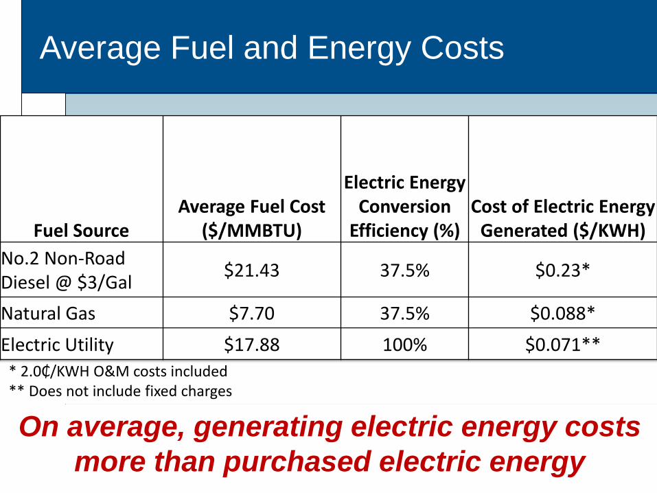
* 2.0₵/KWH O&M costs included** Does not include fixed charges
Average Fuel and Energy Costs
On average, generating electric energy costs
more than purchased electric energy
Fuel SourceAverage Fuel Cost
($/MMBTU)
Electric Energy Conversion
Efficiency (%)Cost of Electric Energy
Generated ($/KWH)
No.2 Non-Road Diesel @ $3/Gal
$21.43 37.5% $0.23*
Natural Gas $7.70 37.5% $0.088*
Electric Utility $17.88 100% $0.071**
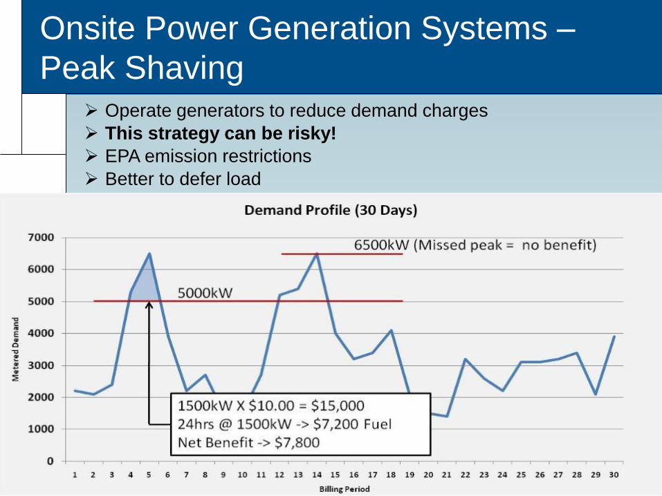
Onsite Power Generation Systems –
Peak Shaving Operate generators to reduce demand charges
This strategy can be risky!
EPA emission restrictions
Better to defer load

Load management is valuable to electric
utilities
Electric Utility Customers
Electric Utility
Electric Cooperative
Utility Grid

Demand Response Programs
End user’s ability to shed load is valuable to
electric utilities
Many electric utilities will pay end users for
“capacity”.
Plant owner is compensated by the utility to
have the standby power generators available
in the event of an utility emergency
Generally less than 100 hours/year of
operation

EPA Emission Requirements
• EPA National Emission Standards for Hazardous Air Pollutants (NESHAP)
Regulates the Carbon Monoxide emissions for existing non-emergency engines
Regulations not applicable to emergency use application and biogas fueled CHP systems.
• EPA New Source Performance Standards (NSPS)
New non-emergency generators must meet stringent emission limits. Most applications require emissions after treatment for non-emergency applications
• Air Permitting

Resource Recovery
79

Energy Sources Available
• Biogas
• Thermal Energy
• Chemical Energy
• Hydraulic Energy
• Renewable Energy
80

Combined Heat and Power
Generation Systems - CHP
Typical WW plant will support 15-30kW of generation
capacity per MGD

Combined Heat and Power Generation
Systems - CHP
35%40%

Biogas to energy systems have been around a
while!
Popular Science
1922
Boy haven’t we come a long way in the last 90 years….
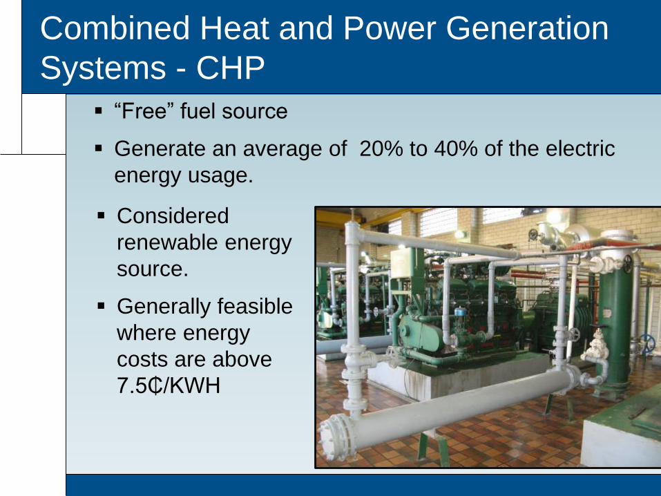
Combined Heat and Power Generation
Systems - CHP
“Free” fuel source
Generate an average of 20% to 40% of the electric
energy usage.
Considered
renewable energy
source.
Generally feasible
where energy
costs are above
7.5₵/KWH

Combined Heat and Power Generation
Systems - CHP
Image Courtesy GE/Jenbacher Engines
Reciprocating Internal Combustion EngineMicroturbine

Combined Heat and Power Generation
Systems - CHPPrime Mover Technology
Common Size Range
(kW)
Typical Electrical
Efficiency (%)
Typical Thermal
Efficiency (%)
Installed Cost ($/kW)
Gas Conditioning
Requirements
Spark Ignited Reciprocating Engines
150-5000kW
35%-40% 25%45% with
exhaust heat recovery
1500 - 2000$/kW with
Heat Recovery
Moderate
Microturbines 30 –250kW
30% 45% 2000-2500 $/kW with
Heat Recovery
High
Fuel Cells 100 –250kW
50% $5000+ Very High
Stirling Engines(New Technology)
~50kW 25% 45% $2500+ Low

Waste Heat Recovery Systems
• Beneficial Uses of Thermal Energy
Digester Heating (Most Common)
Building Heat and Cooling (Absorption
Chillers)
Sludge DryingAbsorption Chiller Process Diagram

Combined Heat and Power Generation
Systems - CHP
CHP systems can be used to drive process
equipment
Offset plants purchased power with
mechanical energy
Common applications are process pumping
and aeration
Benefit is
dependent
on the process
demand.

Combined Heat and Power Generation
Systems - CHP
CHP systems can be used to generate
electricity
Offset plant’s purchased power with electricity
Benefit is not dependent on process
demands.
Possible to
increase benefit
by selling energy
directly the utility.

Energy generated from biogas can be
sold directly to the utility
TREATMENT FACILITY
Utility Meter
Utility Service
CHP System
Offset Purchased
Utility Power Source
OR
Sell Energy Directly
To Electric Utility

0
500
1000
1500
2000
2500
3000
3500
4000
4500
5000
1 2 3 4 5 6 7 8 9 10 11 12 13 14 15 16 17 18 19 20 21 22 23 24 25 26 27 28 29 30
Plant Demand Profile with and without 1000kW CHP System
Demand kWW/O CHP
Demand kWW/ CHP
Utility rates have a significant impact on
CHP system benefit
~1000kW demand loss with 1 day of CHP system
downtime
Peak Demand with 1 day of CHP system downtime
Peak Demand with continuous CHP system operation
CHP Downtime

CHP System Benefit Analysis
SVEC – Rate LP10
• 3 day CHP peak period downtime resulted in a 40% loss of the CHP system benefit for the billing period.
• Demand ratchets can extend the loss for up to 12 months! – 80% 12 month ratchet could result in a loss of ~$170,000/year
ElectricUtility Cost
CHP Demand [email protected]/KW
CHP Energy Offset @ $0.041/KWH
CHPSystem Benefit
CHP System Operation % Savings
No CHP $164,000 N/A N/A N/A N/A
1000kW Base Load –Continuous Operation
$119,200 $17,300 $27,500 $44,800 27%
1000kW Base Load – 1 day CHP Down Time
$133,000 $0 $26,000 $26,000 10%

Some utilities purchase renewable energy
on a energy charge only rate.
$0.00
$0.02
$0.04
$0.06
$0.08
$0.10
$0.12
$0.14
12:0
1am
1:00
am
2:00
am
3:00
am
4:00
am
5:00
am
6:00
am
7:00
am
8:00
am
9:00
am
10:0
0am
11:0
0am
12
:00
pm
1:0
0p
m
2:0
0p
m
3:0
0p
m
4:0
0p
m
5:0
0p
m
6:0
0p
m
7:0
0p
m
8:0
0p
m
9:00
pm
10
:00
pm
11
:00
pm
12
:00
pm
Ener
gy C
ost
$/K
WH
Time of Day
Duke Energy (NC) Rate PP-N Rate Option A
On-PeakMonday-Friday
(9.05¢/kWH)Off-Peak
Weekends and Holidays (5.18¢/kWH)
No Demand Ratcheting!!!!

Benefit may depend on renewable energy portfolio
standards and goals.
www.dsireusa.org
Source:dsireusa.org

Power Monitoring
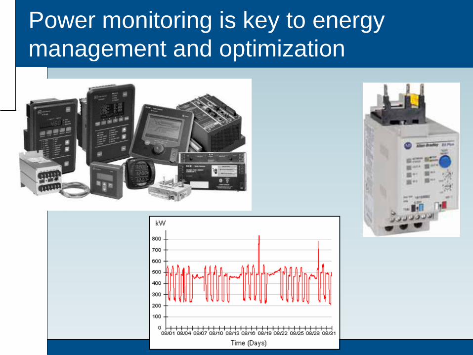
Power monitoring is key to energy
management and optimization

Benefits from incorporating energy usage
data into process operations

Monitor individual loads as well as overall
distribution equipment loads

Power monitoring dashboard example
99

Typical Energy Management
Opportunities
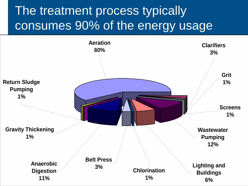
The treatment process typically
consumes 90% of the energy usage
101
Grit
1%
Screens
1%
Clarifiers
3%
Wastewater
Pumping
12%
Lighting and
Buildings
6%
Chlorination
1%
Belt Press
3%Anaerobic
Digestion
11%
Gravity Thickening
1%
Return Sludge
Pumping
1%
Aeration
60%

Secondary TreatmentActivated Sludge with Advanced Treatment and Nitrification
Activated Sludge with Advanced Treatment, No Nitrification
Activated Sludge with No Advanced Treatment or Nitrification
No Activated Sludge, Trickling Filter
kWh/MG
1,000
1,400
1,900
1,600
National Energy Benchmark Data
Source: WEF MOP-32

Energy Optimization – Secondary
Treatment Considerations
• Excessive operating units (too many tanks online)
• DO control (excessively high DO)
• Blower turndown limitations
• Over mixing
• Diffuser fouling
• Inefficient aeration equipment
• Primary clarifier efficiency

Damaged equipment
Damaged Diffuser
Aeration equipment can impact energy
efficiency
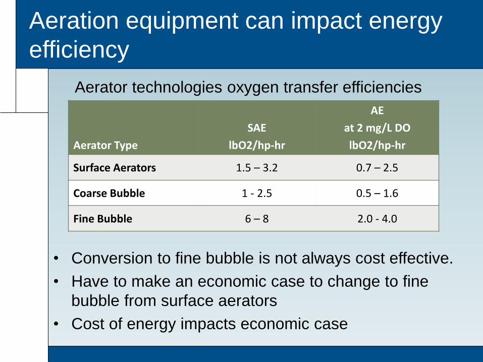
• Conversion to fine bubble is not always cost effective.
• Have to make an economic case to change to fine
bubble from surface aerators
• Cost of energy impacts economic case
Aerator Type
SAE
lbO2/hp-hr
AE
at 2 mg/L DO
lbO2/hp-hr
Surface Aerators 1.5 – 3.2 0.7 – 2.5
Coarse Bubble 1 - 2.5 0.5 – 1.6
Fine Bubble 6 – 8 2.0 - 4.0
Aerator technologies oxygen transfer efficiencies

Questions?
Bryan R. Lisk, PE, CEM
Senior Associate
Hazen and Sawyer – Raleigh Office
(919) 755-8655