siemens digital industries software architecture-driven e
TRANSCRIPT
SIEMENS DIGITAL INDUSTRIES SOFTWARE
Architecture-driven E/E Systems Development Flow
Hans-Juergen Mantsch, Product Management Director, Capital SystemsSiemens Digital Industries Software
siemens.com/software
Across industries, electrical and electronic (E/E)
systems are trending towards increasingly unman-
ageable levels of content and complexity. The
growth in E/E content and complexity requires
new approaches for developing E/E architectures.
How can such approaches be adopted, and how
can these complex architectures be optimized?
This paper explains Siemens’ E/E systems and
architecture design solutions. These advanced
solutions create a powerful digitalized E/E archi-
tecture thread across the product and application
lifecycles, supporting model-based systems engi-
neering (MBSE) methodologies and generating
enormous customer value.
Importantly, the paper explores the strategic
position of the E/E architecture and shows how a
digital thread pivoting around the E/E architecture
can be built: from requirements and systems
modelling, through electrical system, network and
embedded software design, to electronic control
unit and vehicle simulation.
1. Innovation Driven Complexity
Various industries, including automotive, aero-
space and heavy equipment, are experiencing a
huge explosion in “innovation-driven complexity”.
Complexity is exploding due to the introduction of
innovative new technologies including autonomy,
electrification, connected vehicles and data
services. A common characteristic of these innova-
tions is their basis in E/E systems - electrical,
networks and embedded software. This has driven
architectural evolutions to support the greater
demand on the E/E systems.
For example, over the years more and more ECUs
have been added to the automotive architecture.
The ever increasing number of ECUs has
culminated to a point where modern vehicles have
no available space or network bandwidth for addi-
tional ECUs. Recently, the main driver of complexity
has shifted to embedded software as automakers
have begun consolidating ECUs and their features
into a smaller number of high performance compu-
tation nodes.
In addition, cars are no longer isolated devices.
Automakers are enabling their vehicles to connect
to the internet to leverage cloud computing power
and interface with infrastructure services.
Connecting the vehicle to wireless networks, such
as 4G and 5G, demands implementing a sophisti-
cated security strategy to prevent threats to
customer privacy or safety. For example, gateways
that separate in-vehicle and external networks and
advanced firewalls can help ensure that external
actors are unable to access the vehicle’s internal
networks.
1.1. Complexity Metrics
Two key metrics demonstrate the increase in “inno-
vation-driven complexity”: the number of lines of
software code in the vehicle and the number of
network signals on the in-vehicle networks.
In 2014, Deutsche Bank conducted a study in which
they measured rising vehicle complexity based on
the software lines of code (SLOC) and the number
of network signals implemented within a typical
vehicle at various times. The study predicted that
the average vehicle in 2020 would contain 30
million SLOC and 10,000 network signals, both
of which were at least double what was reported
for a vehicle from 2012. This prediction, however,
has proven to fall short of reality. According to
customers, the typical vehicle in 2020 has 150
million SLOC and 20,000 or more network signals.
Abstract
SIEMENS DIGITAL INDUSTRIES SOFTWARE 2
White Paper – Architecture-driven E/E Systems Development Flow
We can see that the worst-case prediction from
2014 has by far been outpaced by reality. Dealing
with this complexity is one of the most substantial
challenges facing the automotive and aerospace
industries.
1.2. Implications across the Industries
Companies are faced with the reality that traditional
methods of product development that have been
used up to this point will no longer suffice.
To cope with the huge levels of innovation-driven
complexity, new methods and strategies of devel-
oping products must be adopted across all indus-
tries. The need for new development methodologies
is only more apparent when considering advanced
technologies, such as autonomous driving function-
ality which requires processing large amounts of
visual sensor data within a reasonable power
budget.
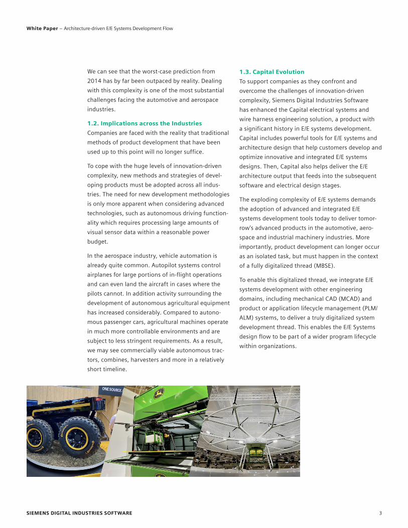
In the aerospace industry, vehicle automation is
already quite common. Autopilot systems control
airplanes for large portions of in-flight operations
and can even land the aircraft in cases where the
pilots cannot. In addition activity surrounding the
development of autonomous agricultural equipment
has increased considerably. Compared to autono-
mous passenger cars, agricultural machines operate
in much more controllable environments and are
subject to less stringent requirements. As a result,
we may see commercially viable autonomous trac-
tors, combines, harvesters and more in a relatively
short timeline.
1.3. Capital Evolution
To support companies as they confront and
overcome the challenges of innovation-driven
complexity, Siemens Digital Industries Software
has enhanced the Capital electrical systems and
wire harness engineering solution, a product with
a significant history in E/E systems development.
Capital includes powerful tools for E/E systems and
architecture design that help customers develop and
optimize innovative and integrated E/E systems
designs. Then, Capital also helps deliver the E/E
architecture output that feeds into the subsequent
software and electrical design stages.
The exploding complexity of E/E systems demands
the adoption of advanced and integrated E/E
systems development tools today to deliver tomor-
row’s advanced products in the automotive, aero-
space and industrial machinery industries. More
importantly, product development can longer occur
as an isolated task, but must happen in the context
of a fully digitalized thread (MBSE).
To enable this digitalized thread, we integrate E/E
systems development with other engineering
domains, including mechanical CAD (MCAD) and
product or application lifecycle management (PLM/
ALM) systems, to deliver a truly digitalized system
development thread. This enables the E/E Systems
design flow to be part of a wider program lifecycle
within organizations.
SIEMENS DIGITAL INDUSTRIES SOFTWARE 3
White Paper – Architecture-driven E/E Systems Development Flow

2. MBSE: Framework and Integrations
E/E systems development is integrated into an
overall MBSE flow through deep connections with
PLM and ALM systems, such as Teamcenter, simula-
tion solutions, MCAD software and other domains
that make up the complete product development
process. This enables a continuous product engi-
neering process, with information constantly
flowing between domains to ensure that each
engineer and team has access to the most up-to-
date data at any given time. MBSE ensures not only
accuracy, but supports better collaboration among
teams, and comprehensive traceability of design
progress.
2.1. MBSE Framework
Key features of the MBSE framework:
• Multi-domain orchestration across engineering
disciplines enables coherent configuration
management, traceability, and capture of engi-
neering deliveries to drive simulation, validation
and verification processes.
• An upfront system definition that aims to serve all
domains with requirements, failure modes and
effects analyses (FMEA), system models and other
multi-domain information models.
• Early simulations on product models enable
large-scale cross-domain verification and product
optimization and trade-off assessments.
2.2. MBSE Product Lifecycle and Multi-Domain
Information Model
Capital is fully embedded into the MBSE process,
delivering the capability to design and optimize
integrated E/E systems, and the implementation of
corresponding electronics, electrical systems, soft-
ware and networks. Let’s explore how MBSE is able
to connect all these development disciplines, and
especially E/E systems development into a coherent
process and design flow.
First, a sophisticated multi-domain information
model allows the E/E systems engineering solution
to capture all product and process related informa-
tion in one place. This information includes feature
and function definitions, requirements, test cases,
feature and product variability models, configura-
tions and any other information needed to describe
the intended product and all related processes,
workflows and release management related
information.
Typically, the product and process information and
models are not created from scratch but originate in
higher abstraction models. These higher abstrac-
tions are usually designed in system engineering or
system modelling solutions, and can be integrated
into the multi-domain information model. The
domain specific engineering solutions for the engi-
neering disciplines then can draw from the informa-
tion and models to drive their specific designs.
These domain-specific designs can also be
connected directly into the overall information
model using various demand-created views or
interfaces. This allows the E/E systems designer
to create the E/E architecture in the context of
the holistic product structure. Engineers can also
leverage important metrics to drive successful E/E
architecture, and subsequent product, designs.
The technical view of the MBSE-enabling multi-do-
main information model is abstracted from the
engineer. Users are only exposed to the underlying
data through sophisticated on-demand and
web-based views. These views are dynamic and
provide data in context of the related engineering
tasks, designs and workflow options. This ensures
that engineers are only presented with information
relevant to their tasks.
SIEMENS DIGITAL INDUSTRIES SOFTWARE 4
White Paper – Architecture-driven E/E Systems Development Flow
3. E/E Systems and Architecture Design
E/E systems and architecture design is an important
piece of this multi-domain information model and
critical to answering the challenges of complexity
in modern products. One of the most effective
strategies to addressing the challenge of innova-
tion-driven complexity is to support continuous
integration of the software and hardware lifecycle,
through ideation, design, implementation and
operation of the product.
3.1. E/E Systems and Software Design
Capital Systems supports such continuous integra-
tion by implementing an E/E systems-driven devel-
opment approach that is fully integrated into the
wider enterprise. The E/E systems development
stage directly feeds architectural proposals for the
network and electrical domains. At the same time,
leveraging data from E/E systems development
enables engineers to balance the hardware vs.
software allocation impact, optimizing the parti-
tioning of the vehicle architecture based on real-
time metrics. These metrics are extensible to include
or measure the effect of changes relative to
design guidelines, supporting trade-studies and
viability checks prior to detail design work begin-
ning. As a result, engineers are able to deliver
optimized architectural proposals to each engi-
neering domain to implement the hardware, soft-
ware, electrical and network domains of the vehicle.
The metrics created during the architecture design
phase can also inform decisions on hosting vehicle
applications locally or in the cloud, including the
consideration of network latency and bandwidth
limitations that can affect application performance.
This sort of analysis is especially important while
partitioning safety critical functionality, such as
automated safety-systems.
Synchronization across the product lifecycle,
continuous integration and coherent complexity
and variability management across all product
design stages and design groups is crucial to
effectively address the challenge of modern product
complexity.
3.2. Electrical Lifecycle
Walking through the lifecycle of a network signal
within the electrical engineering domain provides
an illustrative example of how the E/E systems
design can drive downstream design processes.
Consider two functions, A and B, which are
connected via a signal at the system-level design
abstraction. Each of the functions and the signal
are tied into the multi-domain information model
through Teamcenter requirements, parameters,
validation and test cases and the general product
context made available via links and views.
SIEMENS DIGITAL INDUSTRIES SOFTWARE 5
White Paper – Architecture-driven E/E Systems Development Flow
Through rule-based automation, Capital performs
a set of transformations which translate the func-
tions, A and B, into appropriate devices, electrical
parts with context specific connectors and, finally,
harnesses with harness bundles, fixing material and
harness connectors. The signal-connecting
functions A and B are transformed first into a
electrical net representing the multiplexed network,
then into a shielded twisted pair for the physical
electrical implementation, a harness and lastly into
the bill of process for manufacturing the wiring
harness.
During the automated transformation, or design
synthesis, process, Capital keeps a record of the
identity, links and dependencies between the indi-
vidual artefacts within the different design abstrac-
tions. This establishes traceability from the
manufacturing work instructions all the way up
to the functions, function signals and, of course, to
the product context stored in Teamcenter managed
requirements and test cases.
3.3. Network & Software Lifecycle
What if we look at the same functions A and B, but
from the software and network perspective within
the E/E systems design process?
Through rule-based automation and Capital’s
built-in synthesis technology, the functions can be
transformed into software components, allocated to
specific ECUs, embellished with software behavior
models and configuration information to run on top
of a hardware and software platform within the
targeted ECUs.
As the functions are allocated to different ECUs,
the associated signal is transformed into a network
signal on a multiplexed network and, using timing-
driven network synthesis, packaged into the appro-
priate optimized network frame. Gateways can then
be configured to enable optimized network trans-
mission according to signal priority and the timing
budget allocated to the signal.
The automatically created traceability helps achieve
certification and meet safety requirements. Users
can trace from the functions and signals to the
network input/output, and from the function down
to the specific embedded application configuration
running in the ECU.
3.4. End-to-end Traceability across the E/E
System Integration
Capital’s robust digital thread and automation
capabilities enable the creation of a design flow
unmatched in its capability to exploit automatically
created traceability. Functional models captured
from the multi-domain information model in
Teamcenter are brought into Capital before being
allocated into a vehicle-level view of the topology.
Capital then synthesizes the logical architecture at a
vehicle level for all model variants derived from the
various vehicle configurations. The individual logical
systems are outputs of this process.
Each architecture developed can be saved with the
associated metrics so that trade-off studies of
multiple architectures can be performed. These
studies help engineers to identify the best imple-
mentation option through data-driven metrics
rather than gut feelings. These results of the archi-
tecture trade-off studies are then delivered down-
stream to each of the E/E engineering and
implementation groups.
SIEMENS DIGITAL INDUSTRIES SOFTWARE 6
White Paper – Architecture-driven E/E Systems Development Flow
The traceability across engineering domains can be
exploited at any time. In this example, any element
of the electrical implementation of a network
topology can be traced all the way back to the
requirements managed in Teamcenter, or indeed
to any of the Capital design abstractions, either
upstream or downstream. As an example, the
functional safety criticality of an electrical pin,
part of a multiplexed network connecting ECUs or
line-replaceable units (LRUs), can be assessed in
the context of the functional source, the platform
implementation and test and validation cases.
4. EE Systems Integration Flow
Now we will discuss the steps of the overall process
when the E/E systems design flow is integrated into
the wider enterprise design and implementation
process.
The process begins with the block marked with the
letter [A]. This block shows the Teamcenter product
definition, requirements engineering and system
engineering model. This highest abstraction of the
product composition includes the interfaces
between blocks that model the information that
needs to be transmitted between the multi-domain
system blocks.
Block [B] describes the carry-over designs and
related data in various engineering level details, as
well as data defined in industry standards that are
merged into the system models received from
Teamcenter Systems Modelling Workbench. The
function designs step [C] transform and decompose
the system functions into function designs that are
enriched with domain-specific details to update the
design data carried over from the previous level, or
to create extensions with new functional models.
The domain-enriched function designs replace the
abstract interface definitions from the system
engineering level with low-level domain details.
These enriched function designs also refine and
extend the functional content to the E/E architecture
scope.
The E/E platform designs, as shown in block [D],
capture the logical and physical abstractions of the
architectural implementation. Physical platforms
can be created by importing data from the mechan-
ical CAD environment. These physical platforms
capture the exact physical dimensions, space and
length of the E/E systems implementation to reserve
space in the functional deployment. The E/E archi-
tect can either manually deploy functions to compo-
nents in the architecture, such as ECUs and
assemblies, or use rule-based automation to assign
these functions automatically. Then, function
signals are assigned to communication and ground
carriers as defined in the higher-level system
requirements, or in design rules defined in the
carry-over content.
SIEMENS DIGITAL INDUSTRIES SOFTWARE 7
White Paper – Architecture-driven E/E Systems Development Flow
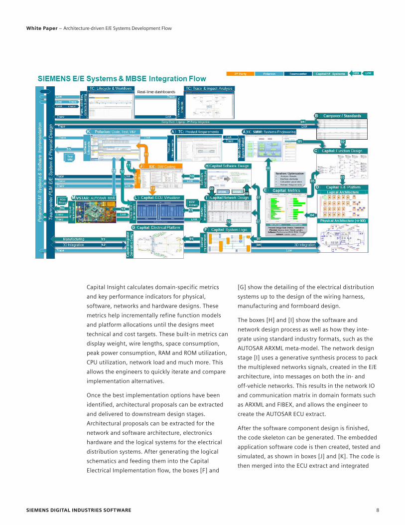
Capital Insight calculates domain-specific metrics
and key performance indicators for physical,
software, networks and hardware designs. These
metrics help incrementally refine function models
and platform allocations until the designs meet
technical and cost targets. These built-in metrics can
display weight, wire lengths, space consumption,
peak power consumption, RAM and ROM utilization,
CPU utilization, network load and much more. This
allows the engineers to quickly iterate and compare
implementation alternatives.
Once the best implementation options have been
identified, architectural proposals can be extracted
and delivered to downstream design stages.
Architectural proposals can be extracted for the
network and software architecture, electronics
hardware and the logical systems for the electrical
distribution systems. After generating the logical
schematics and feeding them into the Capital
Electrical Implementation flow, the boxes [F] and
[G] show the detailing of the electrical distribution
systems up to the design of the wiring harness,
manufacturing and formboard design.
The boxes [H] and [I] show the software and
network design process as well as how they inte-
grate using standard industry formats, such as the
AUTOSAR ARXML meta-model. The network design
stage [I] uses a generative synthesis process to pack
the multiplexed networks signals, created in the E/E
architecture, into messages on both the in- and
off-vehicle networks. This results in the network IO
and communication matrix in domain formats such
as ARXML and FIBEX, and allows the engineer to
create the AUTOSAR ECU extract.
After the software component design is finished,
the code skeleton can be generated. The embedded
application software code is then created, tested and
simulated, as shown in boxes [J] and [K]. The code is
then merged into the ECU extract and integrated
SIEMENS DIGITAL INDUSTRIES SOFTWARE 8
White Paper – Architecture-driven E/E Systems Development Flow
This overview shows how Siemens Digital Industries
Software’s integrated solutions deliver an
unmatched E/E systems development flow for
creating automotive or aerospace architectures.
The flow begins with the multi-domain system
modelling stage that captures the system definitions
and system models in a fully managed environment.
This managed environment provides services for
requirements engineering, change management,
workflow support and asset management. The
abstract multi-domain system models are then
integrated in the E/E architecture stage, where they
are interpreted and decomposed into domain-spe-
cific functions representing the hardware, software,
electrical and electronic content of the final
product.
Functions are deployed in vehicle platforms that
represent the logical and physical abstractions of
the architecture, ECUs, networks and hardware
components. Capital’s rule-based automation and
unique synthesis capability drive a highly efficient
distribution of the functions and related function
signals into the platform. Then, built-in metrics
allow the immediate assessment of the financial or
technical cost of an implementation against the
budget defined by KPIs. With these metrics, engi-
neers can rapidly optimize and iterate the
implementation.
The E/E systems architecture can then be interro-
gated to extract software, network, electrical and
hardware domain-specific architecture proposals.
These proposals can be refined in the respective
design tools in the Capital and Siemens product
portfolio. The software and networks design output
can also be combined to support a synthesis driven,
AUTOSAR embedded software implementation
process.
Establishing bi-directional traceability and
supporting coherent lifecycle management along
all design stages enables a compliance-driven
design flow. In such a design flow, the automatically
created traceability allows engineers to create the
security and functional safety related documenta-
tion needed for product certification.
Capital forms an essential part of this flow. Capital
integrates with PLM, ALM, MCAD, simulation and
other solutions from throughout the Xcelerator
portfolio to create a coherent end to end solution.
This solution ensures digital continuity, multi-do-
main traceability, safety and security for the design
of complex automotive and aerospace systems.
Conclusion
onto a virtual embedded ECU target where it can be
configured, compiled, tested and profiled, as shown
in box [L]. Once the embedded application software
has been validated, it is configured to run on the
target ECU hardware by integrating it onto the
respective AUTOSAR basic software stack in box [M].
Product and application lifecycle management
solutions, such as Teamcenter and Polarion, orches-
trate the overall process and provide traceability
along all design and definition stages of the product
lifecycle. The management of these processes
provides workflow support, impact analysis and task
specific views on the progression of the product
implementation.
SIEMENS DIGITAL INDUSTRIES SOFTWARE 9
White Paper – Architecture-driven E/E Systems Development Flow
About Siemens Digital Industries Software
Siemens Digital Industries Software is driving transformation to
enable a digital enterprise where engineering, manufacturing
and electronics design meet tomorrow. Xcelerator, the compre-
hensive and integrated portfolio of software and services from
Siemens Digital Industries Software, helps companies of all sizes
create and leverage a comprehensive digital twin that provides
organizations with new insights, opportunities and levels of
automation to drive innovation. For more information on
Siemens Digital Industries Software products and services, visit
siemens.com/software or follow us on LinkedIn, Twitter,
Facebook and Instagram. Siemens Digital Industries Software –
Where today meets tomorrow.
siemens.com/software
© 2021 Siemens. A list of relevant Siemens trademarks can be found here. Other trademarks belong to their respective owners.
84032-D4 7/21 K
Siemens Digital Industries Software
Americas: 1 800 498 5351
EMEA: 00 800 70002222
Asia-Pacific: 001 800 03061910
For additional numbers, click here.
About the author
Hans-Juergen Mantsch is the Product Management Director for
Capital Systems, the E/E Systems & Architecture Design front-end
of the Capital Solutions portfolio.