siemens digital industries software reduce power
TRANSCRIPT

Siemens Digital Industries Software
Executive summaryWhen designing or upgrading a building, there are several areas that require significant engineering to ensure they can operate in as green a manner as possible. One of these areas is the chilled water system for air conditioning. In these systems, whether they are primary, primary-second-ary or primary-secondary-tertiary, the pumping energy can account for up to 10 percent of the power required to run the system. Newer system designs are required to meet or exceed pumping power limitations set out by government and industry to improve the efficiency of air-conditioning systems.
Sam Lam K. H., Senior Specialist, Ngee Ann Polytechnic
siemens.com/software
Reduce power consumption of HVAC systems Implementing a new distributed chilled water pumping system for air-conditioning systems

White paper | Reduce power consumption of HVAC system
2Siemens Digital Industries Software
Abstract
Chilled water system designs
These requirements (along with improvements in the efficiency of low-flow, high-head variable speed pumps) led us to investigate other pumping strategies. As part of the work carried out for the building design, Simcenter™ Flomaster™ software was used for compu-tational fluid dynamics (CFD) to investigate a primary-coil secondary pumping system.
For the building being investigated, there were two main areas: The office area received conditioned air from air handling units (AHU) that were cooled by the chilled water system. The other area is a factory floor that does not have air conditioning except for a test area. It is important to note the process equipment on the factory floor is cooled by the same chilled water system as the office area.
Primary-only (P-only) designThe building’s existing chilled water system can be seen in figure 1 and is configured as a primary only pumping system. Two pumps equipped with variable frequency dives (VSD) distribute the chilled water through the system with one of the pumps used as a standby. The speed of the primary pump is controlled so the correct differential pressure is maintained in the loop as measured at the main chilled water header.
Figure 1: P-only chilled water pumping system.

White paper | Reduce power consumption of HVAC system
3Siemens Digital Industries Software
From the pumps, the water is reduced to 10 Celsius (°C) by two screw chillers before being distributed to different AHUs in the building. In the factory and office building, the AHUs are controlled by two-way valves set up to maintain the supply of air temperature at the given setpoint. The process equipment is cooled using plate and frame heat exchangers with modulating control valves determining the flow rate. Several of the smaller spaces such as offices and meeting rooms use fan coil units (FCU) that also use modulating control valves to control the flow.
Figure 2: P-CS chilled water pumping system.
Primary-coil secondary (P-CS) systemTo explore improvements to the current system, a primary-coil secondary system was investigated similar to what is shown in figure 2. This type of system still contains the primary pump and chillers to provide chilled water through the system, but it also has coil pumps at each consumer limit. In this design the primary pumps are used to ensure a minimum flow rate can be maintained without fluctuation throughout the system. The coil pumps replace the modulating and balancing valves and instead control the water flow rate by varying valve openings, directly adjusting rotational speed based on the AHU and FCU temperature require-ments. It is also possible to use a single coil pump to supply multiple loads in a single branch by maintaining the pressure in the loop. By replacing the modulating valves and balancing valves, this can help reduce the pressure drop in the system as well as offset the cost for additional pumps.
White paper | Reduce power consumption of HVAC system
4Siemens Digital Industries Software
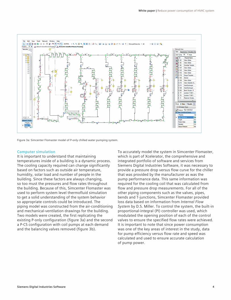
Figure 3a: Simcenter Flomaster model of P-only chilled water pumping system.
Computer simulationIt is important to understand that maintaining temperatures inside of a building is a dynamic process. The cooling capacity required can change significantly based on factors such as outside air temperature, humidity, solar load and number of people in the building. Since these factors are always changing, so too must the pressures and flow rates throughout the building. Because of this, Simcenter Flomaster was used to perform system level thermofluid simulation to get a solid understanding of the system behavior so appropriate controls could be introduced. The piping model was constructed from the air-conditioning and mechanical-ventilation drawings for the building. Two models were created, the first replicating the existing P-only configuration (figure 3a) and the second a P-CS configuration with coil pumps at each demand and the balancing valves removed (figure 3b).
To accurately model the system in Simcenter Flomaster, which is part of Xcelerator, the comprehensive and integrated portfolio of software and services from Siemens Digital Industries Software, it was necessary to provide a pressure drop versus flow curve for the chiller that was provided by the manufacturer as was the pump performance data. This same information was required for the cooling coil that was calculated from flow and pressure drop measurements. For all of the other piping components such as the valves, pipes, bends and T-junctions, Simcenter Flomaster provided loss data based on information from Internal Flow System by D.S. Miller. To control the system, the built-in proportional-integral (PI) controller was used, which modulated the opening position of each of the control valves to ensure the specified flow rates were achieved. It is important to note that since power consumption was one of the key areas of interest in the study, data for pump efficiency versus flow rate and speed was calculated and used to ensure accurate calculation of pump power.

White paper | Reduce power consumption of HVAC system
5Siemens Digital Industries Software
Results and discussionsTwo sets of simulations were run, including one for variable P-only pumping using a fixed pressure setpoint and one of P-CS pumping. For the P-only system, control engineers often control the primary pump speed using the bypass pressure. For the simulations a bypass differential pressure setpoint of 58 kilopascal (kPa) was used based on the simulation of the maximum AHU load conditions. Figure 4 shows pressure along the piping system for full-load conditions. Because the pressure drop in each branch is determined by the pressure setpoint at the bypass, there is not a significant drop based on the load. This means there
Figure 3b: Simcenter Flomaster model of P-CS chilled water pumping system.
is minimal ability to reduce pump head or pump power to become more efficient. The P-CS pumping system is not based on a pressure setpoint. Instead the control will adjust the primary pump speed to ensure the demand for flow of the supply water is being achieved. Figure 5 shows the same pressure profile for the P-CS system. Since the pressure difference at the de-coupler is equal to zero, it has no flow through it, meaning the chilled water is supplied by only the amount needed for each of the demands. As an added benefit, the line pressure in the P-CS system is lower all along the system.
Figure 4. Pressure profile of P-only system at 100 percent load.

White paper | Reduce power consumption of HVAC system
6Siemens Digital Industries Software
Figure 5. Pressure profile of P-CS system at 100 percent load.
It is also important to look at power consumption. Table 1 shows the power consumed by both pumping systems. Overall, the savings of the P-CS system over the P-only system vary significantly. When running at 100 percent demand, the P-CS system could save about 7.4 percent of power. However, when looking at lower flow rates such as 50 percent, the savings could be up to 34 percent. It is also important to note the P-only values assume a fixed constant pressure setpoint optimization, which in the real world is unlikely to be implemented. The potential power savings are expected to be higher than shown here.
As part of the process, the original P-only system had an average specific pumping power of 0.059 kilowatts per tons of refrigeration (kW/RT). After implementing the described P-CS system, the new pump power was measured at 0.032 kW/RT. Table 2 shows the energy consumption of both systems, with the P-CS system saving over 55 percent during a full four-week study.
Table 1. Simulation results - pumping powers.Total pumping power (kW)
Flow Rate savingsP-Only (fixed pressure set point @58 kPa) P-CS
100% 5.08 4.70 7.4%75% 2.71 2.22 18.3%50% 1.40 0.92 34.1%
Table 2. Measured energy consumption after implementation.
SystemsPumping energy
Specific power
kWh kW/RTP-only system 1.727 0.059P-CS systems 773 0.032
Savings 55% 46%

White paper | Reduce power consumption of HVAC system
7Siemens Digital Industries Software
When looking to design a new building or implement an upgraded system to an existing structure, it is important to look at different options for the system design. One of the fastest and most cost effective methods for look-ing at these designs is using 1D CFD tools such as Simcenter Flomaster. In this example, simulating the introduction of efficient low-flow, high-head chilled water pumps meant that using a primary-coil secondary pump system greatly improved the overall efficiency even for a smaller chilled water system.
Conclusion

8
Siemens Digital Industries Software
HeadquartersGranite Park One 5800 Granite Parkway Suite 600 Plano, TX 75024 USA +1 972 987 3000
AmericasGranite Park One 5800 Granite Parkway Suite 600 Plano, TX 75024 USA +1 314 264 8499
EuropeStephenson House Sir William Siemens Square Frimley, Camberley Surrey, GU16 8QD +44 (0) 1276 413200
Asia-PacificUnit 901-902, 9/FTower B, Manulife Financial Centre223-231 Wai Yip Street, Kwun TongKowloon, Hong Kong+852 2230 3333
siemens.com/software© 2020 Siemens. A list of relevant Siemens trademarks can be found here. Other trademarks belong to their respective owners.
82283-C2 8/20 K
About Siemens Digital Industries SoftwareSiemens Digital Industries Software is driving transformation to enable a digital enterprise where engineering, manufacturing and electronics design meet tomorrow. Xcelerator, the comprehensive and integrated portfolio of software and services from Siemens Digital Industries Software, helps companies of all sizes create and leverage a comprehensive digital twin that provides organizations with new insights, opportunities and levels of automation to drive innovation. For more information on Siemens Digital Industries Software products and services, visit siemens.com/software or follow us on LinkedIn, Twitter, Facebook and Instagram. Siemens Digital Industries Software – Where today meets tomorrow.