siemens heating controls residential product selection...
TRANSCRIPT

Siemens Heating Controls
Residential Product
Selection Guide
s

Introduction
Adding controls to your heating system can reduce running costs by 40%*
Siemens Heating Controls are one of theWorld’s leading suppliers of products forthe safe and efficient control of heatingsystems in residential installations. Ourreputation is second to none, we aim tomaintain this reputation through ourcommitment to design and product quality,backed by a dedicated technical supportteam.
Our highly trained and knowledgeableteam can be contacted on a local ratenumber 0870 850 0184 from anywhere inthe UK.
Siemens Heating Controls is part of one ofthe largest global electrical andengineering groups.
Throughout a 160 year history of provenresearch and engineering talent, with morethan 50,000 active patents, Siemens hascontinuously provided its customers withinnovations in the areas of healthcare,energy, industry, and infrastructure –globally and locally.
*Recent independent tests by the University of Salford comparing a conventional heating system with no controlsagainst the same system with a room thermostat and TRVs added.
Energy used(%)
Heating
HotWater
Cooking
Appliances
Lighting
With a 40% saving onyour heating you couldachieve a 25% drop inyour overall energy bills
A high quality electronicroom thermostat will turn
off the boiler when thehouse is warm enough.
Choosing a suitableprogrammer will allow youto adjust heating times to
match your lifestyle.
Thermostatic radiatorvalves (TRVs) ensure thatyou only heat the rooms
you need.
A properly installed heating controlsystem will maintain suitabletemperatures in every room in yourhome, prevent wasted heat and makesure your boiler runs efficiently.
Heating controls from Siemens are costeffective and readily available.
They are also easy to fit and can beinstalled with minimal disruption.
40%SAVING

Contents 3
Room Thermostats
RDD100 • RDD100.1 • RDD100.1DHW • RDH10-GBRAA20LD-GB • RAA21-GB • RAA31.16 • RAA11
Programmable Room Thermostats
RDE100 • RDE100.1 • RDE100.1DHW • RDJ10-GB REV13 • REV17 • REV24 • RAV11.1 • RAV11.7
Wireless Thermostats
RDH10RF/SET-GB • RDJ10RF/SET-GB • RDH10RF/SET-CYL • RDD100.1RFSRDE100.1RFS • REV24RF/SET • RDE-MZ6 • RDD100.1RF • RDE100.1RF
Cylinder, Pipe and Frost Thermostats
RAM1 • RAM1T • RAA11
Motorised Valves
CZV... • CMV... • Demountable Actuator
Thermostatic Radiator and By-pass Valves
MTN51GB • Trade TRV • Trade TRV2 • BPV22 • TRV packs and value packs
Product interchange and wiring guide
Time Controls
RWB27 • RWB27Si • RWB29 • RWB29Si • RWB30e • RWB2e RWB1001 • RWB1007 • RWB2001 • RWB2007
4-7
8-11
12-15
16-19
20-21
22
23-26
28-51
Product selection guide index 27
For technical specifications and further information please refer to our website www.siemens.co.uk/residential-controls
3
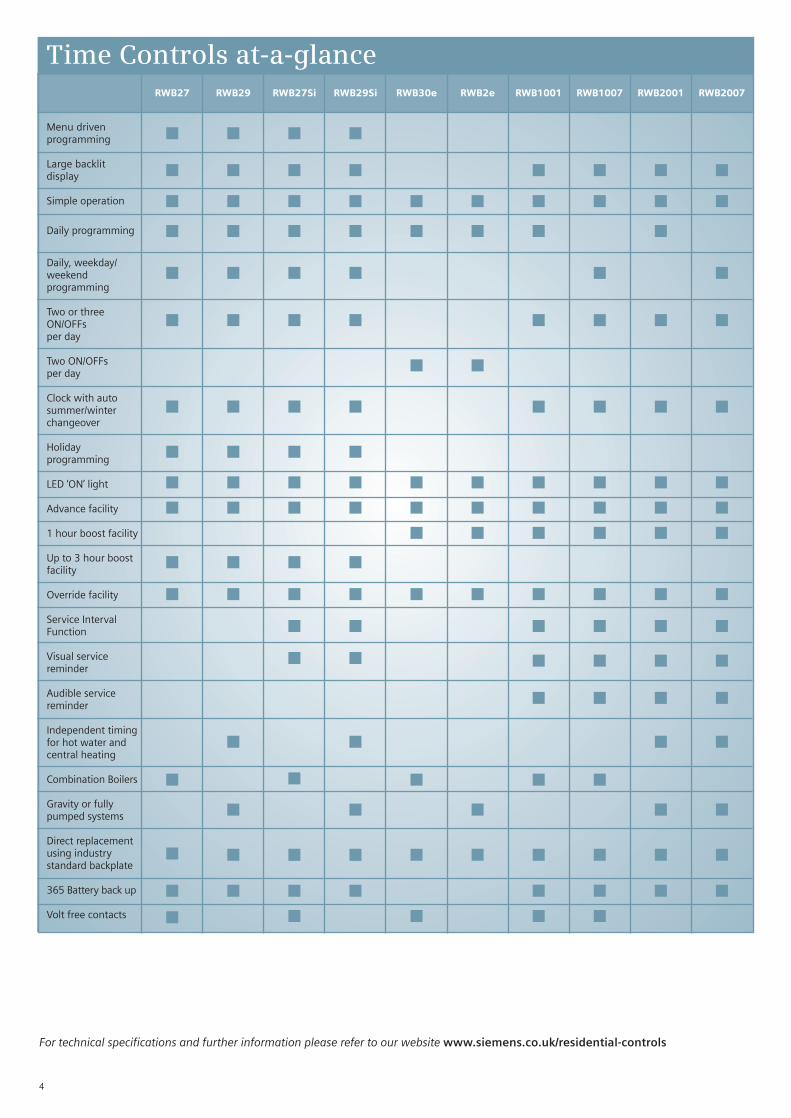
Time Controls at-a-glance
For technical specifications and further information please refer to our website www.siemens.co.uk/residential-controls
4
RWB27
g
g
g
g
g
g
g
g
g
g
g
g
g
g
g
g
RWB29
g
g
g
g
g
g
g
g
g
g
g
g
g
g
g
g
RWB27Si
g
g
g
g
g
g
g
g
g
g
g
g
g
g
g
g
g
g
RWB29Si
g
g
g
g
g
g
g
g
g
g
g
g
g
g
g
g
g
g
RWB30e
g
g
g
g
g
g
g
g
g
g
RWB2e
g
g
g
g
g
g
g
g
g
RWB1001
g
g
g
g
g
g
g
g
g
g
g
g
g
g
g
g
RWB1007
g
g
g
g
g
g
g
g
g
g
g
g
g
g
g
g
RWB2001
g
g
g
g
g
g
g
g
g
g
g
g
g
g
g
g
RWB2007
g
g
g
g
g
g
g
g
g
g
g
g
g
g
g
g
Menu drivenprogramming
Large backlitdisplay
Simple operation
Daily programming
Daily, weekday/weekendprogramming
Two or threeON/OFFsper day
Two ON/OFFsper day
Clock with autosummer/winterchangeover
Holidayprogramming
LED ‘ON’ light
Advance facility
1 hour boost facility
Up to 3 hour boostfacility
Override facility
Service IntervalFunction
Visual servicereminder
Audible servicereminder
Independent timingfor hot water andcentral heating
Combination Boilers
Gravity or fullypumped systems
Direct replacementusing industrystandard backplate
365 Battery back up
Volt free contacts

For technical specifications and further information please refer to our website www.siemens.co.uk/residential-controls
RWB27 Timer
RWB29 Programmer
5
Time Controls RWB27 • RWB27Si • RWB29 • RWB29Si
RWB29Si Programmer
RWB27Si Timer
Same functionality as RWB29 but withthe following additional feature:
■ Service interval function
Operating voltage: AC230V ± 10%
Contact rating: 6A Resistive 2A Inductive
Dimensions: 145mm x 90mm x 34mm
■ Unique menu driven programming
■ Easy to read, larger than averagebacklit display
■ Daily, weekday/weekend or7 day programming
■ Advance and up to 3 hour boost facility
■ 2/3 ON/OFFs per day
■ Holiday programming
■ LED ‘ON’ lamps
■ Battery back-up
■ Industry standard backplate
■ Ideal for Gravity or fully pumped systems
Operating voltage: AC230V ± 10%
Contact rating: 6A Resistive 2A Inductive
Dimensions: 145mm x 90mm x 34mm
■ Unique menu driven programming
■ Easy to read, larger than averagebacklit display
■ Daily, weekday/weekend or7 day programming
■ Advance and up to 3 hour boost facility
■ 2/3 ON/OFFs per day
■ Holiday programming
■ LED ‘ON’ lamp
■ Battery back-up
■ Volt free contacts 12-250V
■ Industry standard backplate
■ Ideal for Combination Boilers
Operating voltage: AC230V ± 10%
Contact rating: 6A Resistive 2A Inductive
Dimensions: 145mm x 90mm x 34mm
Same functionality as RWB27 but withthe following additional feature:
■ Service interval function
Operating voltage: AC230V ± 10%
Contact rating: 6A Resistive 2A Inductive
Dimensions: 145mm x 90mm x 34mm
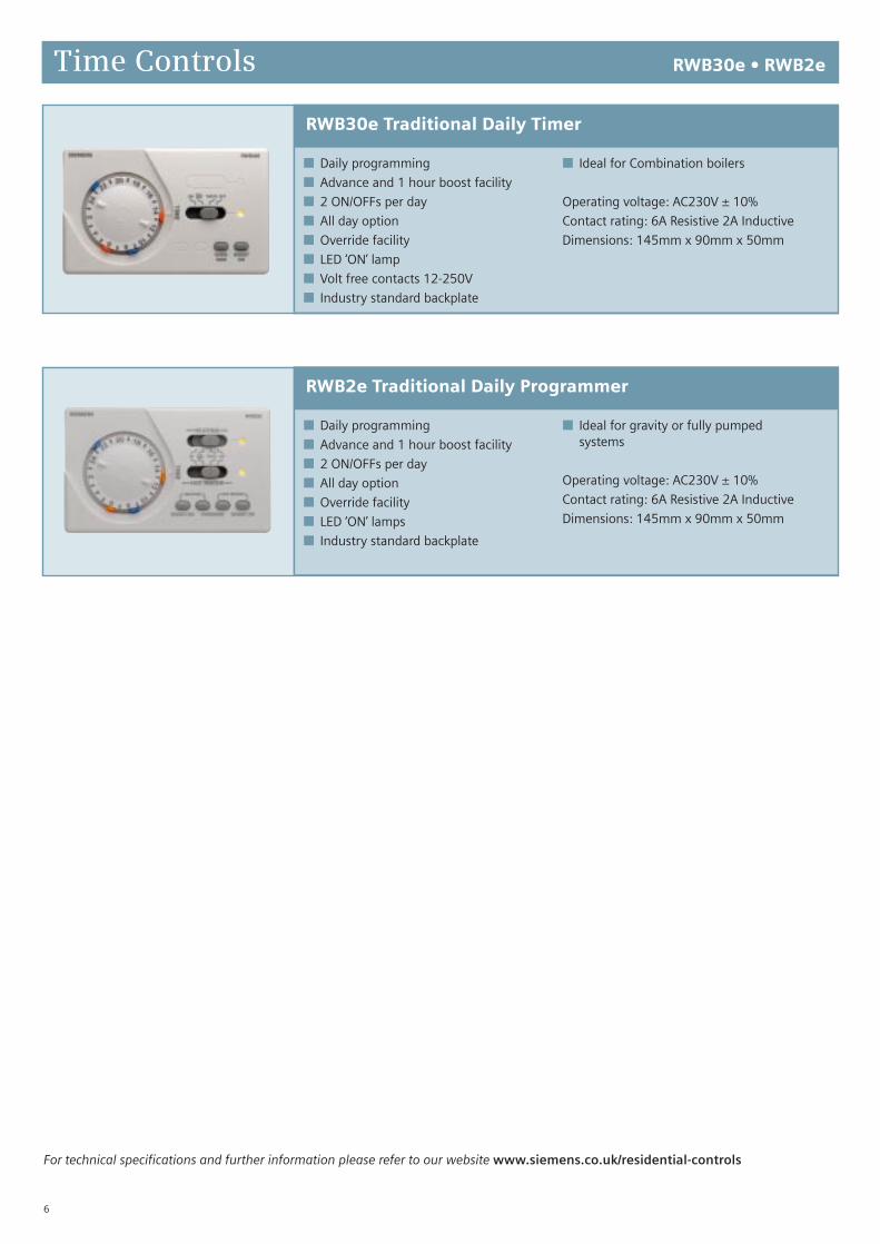
Time Controls RWB30e • RWB2e
RWB30e Traditional Daily Timer
RWB2e Traditional Daily Programmer
■ Daily programming
■ Advance and 1 hour boost facility
■ 2 ON/OFFs per day
■ All day option
■ Override facility
■ LED ‘ON’ lamps
■ Industry standard backplate
■ Ideal for gravity or fully pumped systems
Operating voltage: AC230V ± 10%
Contact rating: 6A Resistive 2A Inductive
Dimensions: 145mm x 90mm x 50mm
For technical specifications and further information please refer to our website www.siemens.co.uk/residential-controls
6
■ Daily programming
■ Advance and 1 hour boost facility
■ 2 ON/OFFs per day
■ All day option
■ Override facility
■ LED ‘ON’ lamp
■ Volt free contacts 12-250V
■ Industry standard backplate
■ Ideal for Combination boilers
Operating voltage: AC230V ± 10%
Contact rating: 6A Resistive 2A Inductive
Dimensions: 145mm x 90mm x 50mm

Time Controls RWB1001 • RWB1007 • RWB2001 • RWB2007
For technical specifications and further information please refer to our website www.siemens.co.uk/residential-controls
RWB1001 Timer
RWB1007 Timer
RWB2001 Programmer
RWB2007 Programmer
7
■ Easy to read backlit display
■ Daily programming
■ Advance and 1 hour boost facility
■ 2/3 ON/OFFs per day
■ Clock with auto summer/winterchangeover
■ Clock supplied preset to correct timeand date
■ LED ‘ON’ lamp
■ Service interval capable
■ Audio and visual service reminder
■ Battery back-up
■ Volt free contacts 12-250V
■ Industry standard backplate
■ Ideal for Combination boilers
Operating voltage: AC230V ± 10%
Contact rating: 6A Resistive 2A Inductive
Dimensions: 145mm x 85mm x 34mm
■ Easy to read backlit display
■ Daily, weekday/weekend or 7 day
■ Advance and 1 hour boost facility
■ 2/3 ON/OFFs per day
■ Clock with auto summer/winterchangeover
■ Clock supplied preset to correct timeand date
■ LED ‘ON’ lamp
■ Service interval capable
■ Audio and visual service reminder
■ Battery back-up
■ Volt free contacts 12-250V
■ Industry standard backplate
■ Ideal for Combination boilers
Operating voltage: AC230V ± 10%
Contact rating: 6A Resistive 2A Inductive
Dimensions: 145mm x 85mm x 34mm
■ Easy to read backlit display
■ Daily programming
■ Advance and 1 hour boost facility
■ 2/3 ON/OFFs per day
■ Clock with auto summer/winterchangeover
■ Clock supplied preset to correct timeand date
■ LED ‘ON’ lamps
■ Service interval capable
■ Audio and visual service reminder
■ Battery back-up
■ Industry standard backplate
■ Ideal for gravity or fully pumped systems
Operating voltage: AC230V ± 10%
Contact rating: 6A Resistive 2A Inductive
Dimensions: 145mm x 85mm x 34mm
■ Easy to read backlit display
■ Daily, weekday/weekend or7 day programming
■ Advance and 1 hour boost facility
■ 2/3 ON/OFFs per day
■ Clock with auto summer/winterchangeover
■ Clock supplied preset to correct timeand date
■ LED ‘ON’ lamps
■ Service interval capable
■ Audio and visual service reminder
■ Battery back-up
■ Industry standard backplate
■ Ideal for gravity or fully pumped systems
Operating voltage: AC230V ± 10%
Contact rating: 6A Resistive 2A Inductive
Dimensions: 145mm x 85mm x 34mm

Room Thermostats at-a-glance
For technical specifications and further information please refer to our website www.siemens.co.uk/residential-controls
8
RAA20LD-GB
g
g
g
g
g
g
g
g
g
g
RAA21-GB
g
g
g
g
g
g
g
g
g
RAA31.16
g
g
g
g
g
g
g
g
g
g
RAA11
g
g
g
g
g
g
g
g
g
g
RDD100
g
g
g
g
g
g
g
g
g
g
RDD100.1
g
g
g
g
g
g
g
g
g
g
RDD100.1DHW
g
g
g
g
g
g
g
g
g
RDH10-GB
g
g
g
g
g
g
g
g
Combination Boilers
Gas filled bellows
24 - 250V
Changeover contacts
Setting range 5°C - 30°C
Setting range 5°C - 35°C
Limiting or locking facility
Setback temperature 5°C - 35°C
Double Insulated (no earth required)
Electronic display
LED ‘ON’ light
Heating or cooling operation
Tamperproof
5 Amp rated
6 Amp rated
ON/OFF switch
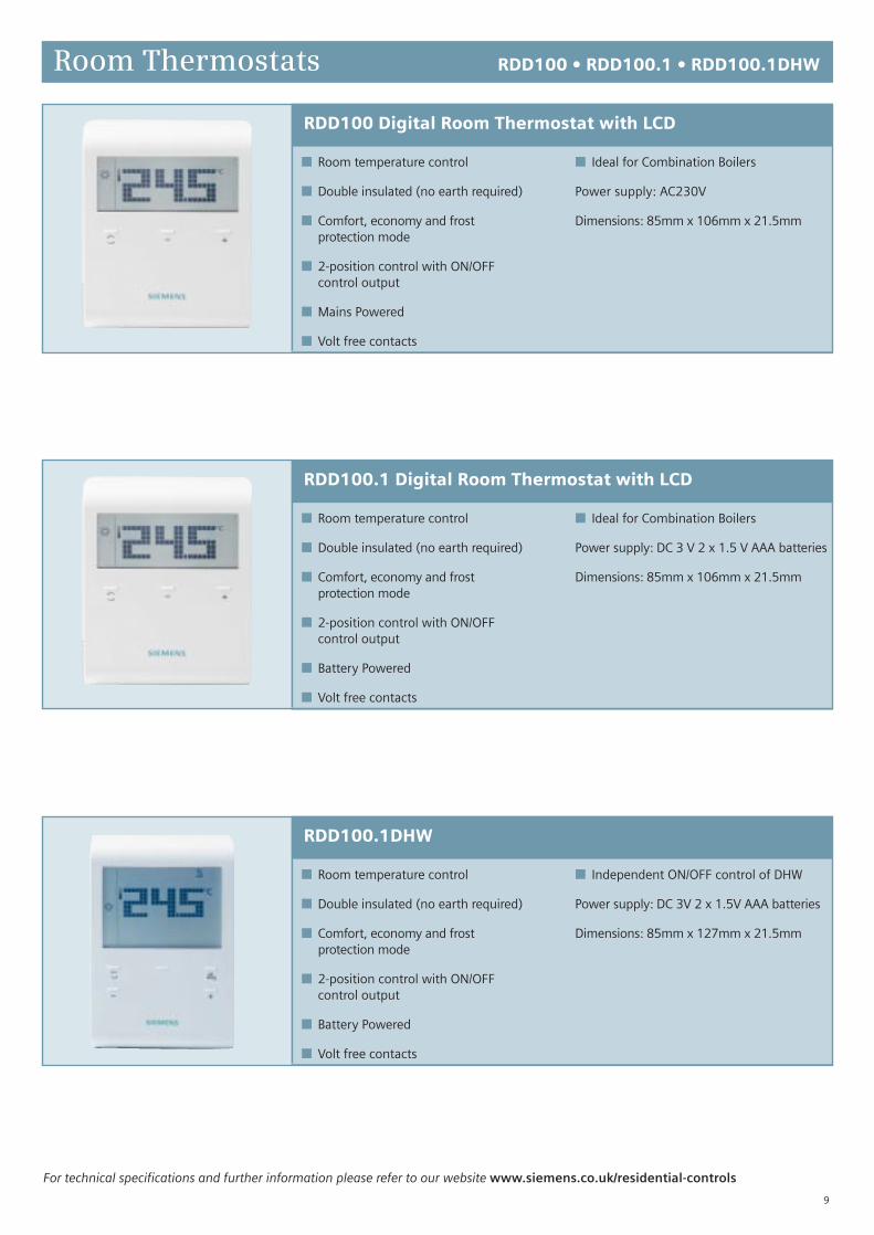
Room Thermostats RDD100 • RDD100.1 • RDD100.1DHW
For technical specifications and further information please refer to our website www.siemens.co.uk/residential-controls
9
RDD100 Digital Room Thermostat with LCD
RDD100.1 Digital Room Thermostat with LCD
RDD100.1DHW
■ Room temperature control
■ Double insulated (no earth required)
■ Comfort, economy and frostprotection mode
■ 2-position control with ON/OFFcontrol output
■ Mains Powered
■ Volt free contacts
■ Ideal for Combination Boilers
Power supply: AC230V
Dimensions: 85mm x 106mm x 21.5mm
■ Room temperature control
■ Double insulated (no earth required)
■ Comfort, economy and frostprotection mode
■ 2-position control with ON/OFFcontrol output
■ Battery Powered
■ Volt free contacts
■ Ideal for Combination Boilers
Power supply: DC 3 V 2 x 1.5 V AAA batteries
Dimensions: 85mm x 106mm x 21.5mm
■ Room temperature control
■ Double insulated (no earth required)
■ Comfort, economy and frostprotection mode
■ 2-position control with ON/OFFcontrol output
■ Battery Powered
■ Volt free contacts
■ Independent ON/OFF control of DHW
Power supply: DC 3V 2 x 1.5V AAA batteries
Dimensions: 85mm x 127mm x 21.5mm
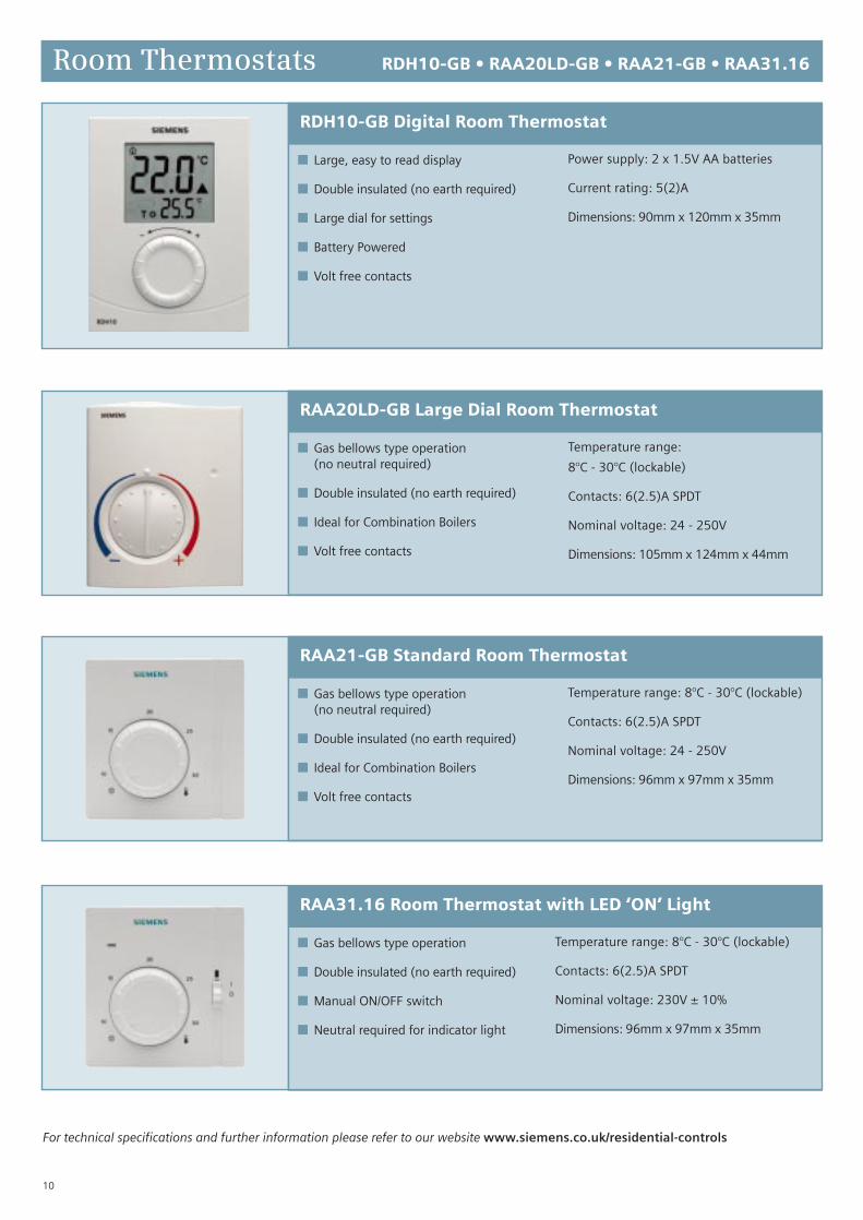
RAA21-GB Standard Room Thermostat
RAA20LD-GB Large Dial Room Thermostat
RAA31.16 Room Thermostat with LED ‘ON’ Light
Room Thermostats RDH10-GB • RAA20LD-GB • RAA21-GB • RAA31.16
For technical specifications and further information please refer to our website www.siemens.co.uk/residential-controls
10
■ Gas bellows type operation(no neutral required)
■ Double insulated (no earth required)
■ Ideal for Combination Boilers
■ Volt free contacts
Temperature range:
8°C - 30°C (lockable)
Contacts: 6(2.5)A SPDT
Nominal voltage: 24 - 250V
Dimensions: 105mm x 124mm x 44mm
■ Gas bellows type operation(no neutral required)
■ Double insulated (no earth required)
■ Ideal for Combination Boilers
■ Volt free contacts
Temperature range: 8°C - 30°C (lockable)
Contacts: 6(2.5)A SPDT
Nominal voltage: 24 - 250V
Dimensions: 96mm x 97mm x 35mm
■ Gas bellows type operation
■ Double insulated (no earth required)
■ Manual ON/OFF switch
■ Neutral required for indicator light
Temperature range: 8°C - 30°C (lockable)
Contacts: 6(2.5)A SPDT
Nominal voltage: 230V ± 10%
Dimensions: 96mm x 97mm x 35mm
RDH10-GB Digital Room Thermostat
■ Large, easy to read display
■ Double insulated (no earth required)
■ Large dial for settings
■ Battery Powered
■ Volt free contacts
Power supply: 2 x 1.5V AA batteries
Current rating: 5(2)A
Dimensions: 90mm x 120mm x 35mm

For technical specifications and further information please refer to our website www.siemens.co.uk/residential-controls
11
Room Thermostats RAA11
RAA11 Tamperproof Double Insulated Room Thermostat
■ Gas bellows type operation(no neutral required)
■ Double insulated (no earth required)
■ Tamperproof
■ Suitable for use as a frost thermostat
■ Ideal for Combination Boilers
Temperature range:8°C - 30°C (lockable)
Contacts: 6(2.5)A SPDT
Nominal voltage: 24 - 250V
Dimensions: 96mm x 97mm x 35mm

Programmable Room Thermostats at-a-glance
For technical specifications and further information please refer to our website www.siemens.co.uk/residential-controls
12
RDJ10-GB
g
g
g
g
g
g
g
g
g
g
RAV11.1
g
g
g
g
g
g
g
g
g
g
g
g
RAV11.7
g
g
g
g
g
g
g
g
g
g
g
g
REV13
g
g
g
g
g
g
g
g
g
g
g
g
g
REV17
g
g
g
g
g
g
g
g
g
g
g
g
g
REV24
g
g
g
g
g
g
g
g
g
g
g
g
g
g
g
g
RDE100
g
g
g
g
g
g
g
g
g
g
g
g
g
g
RDE100.1
g
g
g
g
g
g
g
g
g
g
g
g
g
g
RDE100.1DHW
g
g
g
g
g
g
g
g
g
g
g
g
g
Combination Boilers
Underfloor heating
Self-learning logic
Digital display
Programmable awayfrom backplate
PID (TPI) control
24 - 250V
Analogue clock
Daily programming
Weekday/weekendprogramming
7 day programming
Lockable display
Holiday programming
Setback facility
Frost protection
Changeover contacts
Party mode (up to 9 hour boost)
5 Amp rated
6 Amp rated
8 Amp rated

For technical specifications and further information please refer to our website www.siemens.co.uk/residential-controls
13
RDJ10-GB Programmable Room Thermostat
RDE100.1 Programmable Room Thermostat
RDE100 Programmable Room Thermostat
Programmable Room ThermostatsRDE100 • RDE100.1 • RDE100.1DHW • RDJ10-GB
■ Large, easy to read LCD display
■ Double insulated (no earth required)
■ Large dial for settings
■ Daily programming
■ Battery powered
■ Volt free contacts
■ Ideal for combination boilers
Power supply: 2 x 1.5V AA batteries
Current rating: 5(2)A
Dimensions: 90mm x 120mm x 35mm
RDE100.1DHW
■ Room temperature control
■ Double insulated (no earth required)
■ Daily, weekday/weekend or7 day programming
■ Comfort, economy andfrost protection mode
■ 2-position control with ON/OFFcontrol output
■ Holiday programming
■ Battery powered
■ Volt free contacts
■ Ideal for combination boilers
Power supply: 2 x 1.5V AAA batteries
Current rating: 5(2)A
Dimensions: 85mm x 127mm x 21.5mm
■ Room temperature control
■ Double insulated (no earth required)
■ Daily, weekday/weekend or7 day programming
■ Comfort, economy andfrost protection mode
■ 2-position control with ON/OFFcontrol output
■ Holiday programming
■ Battery Powered
■ Volt free contacts
■ Independent ON/OFF control of DHW
Power supply: DC 3V 2 x 1.5V AAA batteries
Dimensions: 85mm x 127mm x 21.5mm
■ Room temperature control
■ Double insulated (no earth required)
■ Daily, weekday/weekend or7 day programming
■ Comfort, economy andfrost protection mode
■ 2-position control with ON/OFFcontrol output
■ Holiday programming
■ Mains powered
■ Volt free contacts
■ Ideal for combination boilers
Power supply: AC230V
Current rating: 5(2)A
Dimensions: 85mm x 127mm x 21.5mm
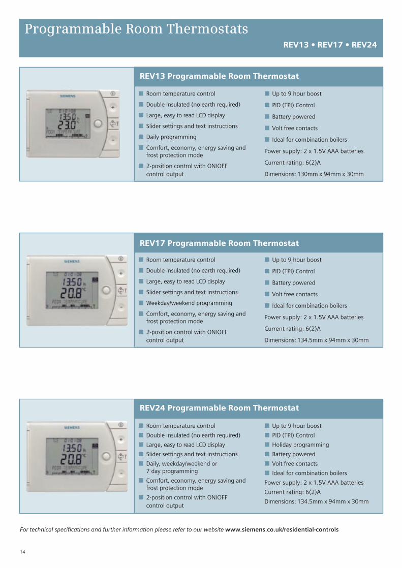
Programmable Room ThermostatsREV13 • REV17 • REV24
For technical specifications and further information please refer to our website www.siemens.co.uk/residential-controls
14
REV24 Programmable Room Thermostat
REV17 Programmable Room Thermostat
REV13 Programmable Room Thermostat
■ Room temperature control
■ Double insulated (no earth required)
■ Large, easy to read LCD display
■ Slider settings and text instructions
■ Daily programming
■ Comfort, economy, energy saving andfrost protection mode
■ 2-position control with ON/OFFcontrol output
■ Up to 9 hour boost
■ PID (TPI) Control
■ Battery powered
■ Volt free contacts
■ Ideal for combination boilers
Power supply: 2 x 1.5V AAA batteries
Current rating: 6(2)A
Dimensions: 130mm x 94mm x 30mm
■ Room temperature control
■ Double insulated (no earth required)
■ Large, easy to read LCD display
■ Slider settings and text instructions
■ Weekday/weekend programming
■ Comfort, economy, energy saving andfrost protection mode
■ 2-position control with ON/OFFcontrol output
■ Up to 9 hour boost
■ PID (TPI) Control
■ Battery powered
■ Volt free contacts
■ Ideal for combination boilers
Power supply: 2 x 1.5V AAA batteries
Current rating: 6(2)A
Dimensions: 134.5mm x 94mm x 30mm
■ Room temperature control
■ Double insulated (no earth required)
■ Large, easy to read LCD display
■ Slider settings and text instructions
■ Daily, weekday/weekend or7 day programming
■ Comfort, economy, energy saving andfrost protection mode
■ 2-position control with ON/OFFcontrol output
■ Up to 9 hour boost
■ PID (TPI) Control
■ Holiday programming
■ Battery powered
■ Volt free contacts
■ Ideal for combination boilers
Power supply: 2 x 1.5V AAA batteries
Current rating: 6(2)A
Dimensions: 134.5mm x 94mm x 30mm
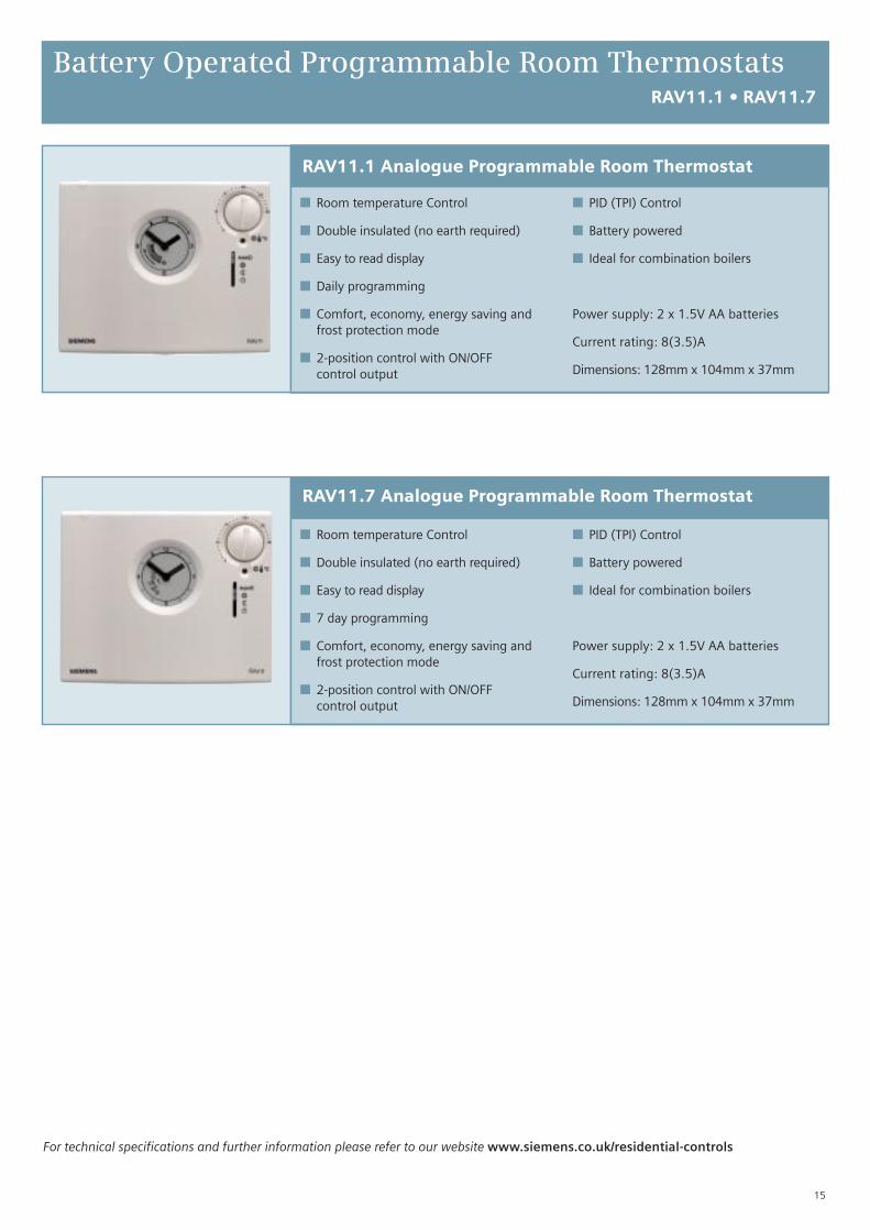
Battery Operated Programmable Room ThermostatsRAV11.1 • RAV11.7
For technical specifications and further information please refer to our website www.siemens.co.uk/residential-controls
15
RAV11.7 Analogue Programmable Room Thermostat
RAV11.1 Analogue Programmable Room Thermostat
■ Room temperature Control
■ Double insulated (no earth required)
■ Easy to read display
■ Daily programming
■ Comfort, economy, energy saving andfrost protection mode
■ 2-position control with ON/OFFcontrol output
■ PID (TPI) Control
■ Battery powered
■ Ideal for combination boilers
Power supply: 2 x 1.5V AA batteries
Current rating: 8(3.5)A
Dimensions: 128mm x 104mm x 37mm
■ Room temperature Control
■ Double insulated (no earth required)
■ Easy to read display
■ 7 day programming
■ Comfort, economy, energy saving andfrost protection mode
■ 2-position control with ON/OFFcontrol output
■ PID (TPI) Control
■ Battery powered
■ Ideal for combination boilers
Power supply: 2 x 1.5V AA batteries
Current rating: 8(3.5)A
Dimensions: 128mm x 104mm x 37mm

RF (Wireless) Thermostats at-a-glance
For technical specifications and further information please refer to our website www.siemens.co.uk/residential-controls
16
Combination Boilers
Underfloor heating
24 - 250V voltfree contacts
Large digital display
Backlit display
Setback facility
Changeover contacts
Advance
Daily programming
Weekday/weekendprogramming
7 day programming
Large control dial
PID (TPI) control
433Mhz
868Mhz
Double insulated
Holiday programming
Frost protection
Override
Manual overrideswitch (on receiver)
Party mode(up to 9 hour boost)
RF signal strengthindicator
RDJ10RF/SET-GB
g
g
g
g
g
g
g
g
g
g
g
g
g
g
RDH10RF/SET-GB
g
g
g
g
g
g
g
g
g
RDD100.1RFS
g
g
g
g
g
g
g
g
g
g
RDE100.1RFS
g
g
g
g
g
g
g
g
g
g
g
g
g
g
g
REV24RF/SET
g
g
g
g
g
g
g
g
g
g
g
g
g
g
g
g
g
g
g
g
RDE-MZ6
g
g
g
g
g
g
g
RDD100.1RF
g
g
g
g
g
g
g
g
g
g
RDE100.1RF
g
g
g
g
g
g
g
g
g
g
g
g
g
g
g
RDHRF/SET-CYL
g
g
g
g
g
g
g

Wireless Thermostats RDH10RF/SET • RDJ10RF/SET • RDH10RF/SET-CYL
RDH10RF/SET-CYL Wireless cylinderthermostat and receiver
RDH10RF/SET-GB Wireless digital roomthermostat and receiver
RDJ10RF/SET-GB Wireless programmable roomthermostat and receiver
For technical specifications and further information please refer to our website www.siemens.co.uk/residential-controls
17
■ Large, easy to read LCD display
■ Double insulated (no earth required)
■ Large dial for settings
■ Manual override
■ Battery powered
■ Volt free contacts
■ Range 20 metres line of sight between transmitter and receiver
Power supply: 2 x 1.5V AA batteries
Current rating: 8(3)A
Dimensions: 90mm x 120mm x 35mm
■ Large, easy to read LCD display
■ Double insulated (no earth required)
■ Large dial for settings
■ Manual override
■ Daily programming
■ Battery powered
■ Volt free contacts
■ Range 20 metres line of sight between transmitter and receiver
Power supply: 2 x 1.5V AA batteries
Current rating: 8(3)A
Dimensions: 90mm x 120mm x 35mm
■ Large, easy to read LCD display
■ Double insulated (no earth required)
■ Large dial for settings
■ Manual override
■ Battery powered
■ Volt free contacts
■ Range 20 metres line of sight between transmitter and receiver
Power supply: 2 x 1.5V AA batteries
Current rating: 8(3)A
Dimensions: 90mm x 120mm x 35mm

Wireless Thermostats RDD100.1RFS • RDE100.1RFS • REV24RF/SET
RDD100.1RFS Wireless digital roomthermostat and receiver
RDE100.1RFS Wireless programmableroom thermostat and receiver
REV24RF/SET Wireless programmable roomthermostat and receiver
For technical specifications and further information please refer to our website www.siemens.co.uk/residential-controls
18
■ Room temperature control
■ Double insulated (no earth required)
■ Comfort, economy and frost protection mode
■ Battery powered
■ Volt free contacts
■ Unique RF signalling
■ Range 20 metres line of sight between transmitter and receiver
Power supply: 2 x 1.5V AAA batteries
Current rating: 8(3)A
Dimensions: 85mm x 106mm x 22mm
■ Double insulated (no earth required)■ Daily, weekday/weekend or 7 day programming■ Slider settings and text instructions■ Signal strength indicator■ PID (TPI) control■ Comfort, economy and frost protection mode■ Automatic summer/winter changeover■ Up to 9 hour boost■ Holiday programming■ Battery powered■ Volt free contacts■ Ideal for combination boilers■ Range 20 metres line of sight between transmitter and receiverPower supply: 2 x 1.5V AA batteriesCurrent rating: 16(2)ADimensions: 134.5mm x 94mm x 30mm
■ Room temperature control■ Double insulated (no earth required)■ Daily, weekday/weekend or 7 day programming■ Comfort, economy and frost protection mode■ 2-position control with ON/OFF control output■ Holiday programming■ Battery powered■ Volt free contacts■ Ideal for combination boilers■ Unique RF signalling■ Range 20 metres line of sight between transmitter and receiverPower supply: 2 x 1.5V AAA batteriesCurrent rating: 8(3)ADimensions: 85mm x 127mm x 22mm

Wireless Thermostats RDE-MZ6 • RDD100.1RF • RDE100.1RF
RDD100.1RF Wireless programmableroom thermostat
RDE100.1RF Wireless programmableroom thermostat
For technical specifications and further information please refer to our website www.siemens.co.uk/residential-controls
19
RDE-MZ6 Wireless multizone receiver
■ For use with RDE-MZ6 multizone receiver
■ Room temperature control
■ Double insulated (no earth required)
■ Daily, weekday/weekend or 7 day programming
■ Comfort, economy and frost protection mode
■ 2-position control with ON/OFF control output
■ Holiday programming
■ Battery powered
■ Range 20 metres line of sight between transmitter and receiver
Power supply: 2 x 1.5V AA batteries
Dimensions: 85mm x 127mm x 21.5mm
■ For use with RDE-MZ6 multizone receiver
■ Room temperature control
■ Double insulated (no earth required)
■ Comfort, economy and frost protection mode
■ Battery powered
■ Range 20 metres line of sight between transmitter and receiver
Power supply: 2 x 1.5V AA batteries
Dimensions: 85mm x 106mm x 21.5mm
Only for use in conjunction with RDD100.1RF and RDE100.1RF roomthermostats (to be ordered separately)
■ Up to 6 devices can be connected for independent control ofeach room/zone
■ Easy and quick installation due to new design and easily identifiableterminal markings
■ Simple pairing of operation helps reduce installation time
■ Indication of operating status via LEDs
■ External antenna for multizone installation inside a metal enclosureor weak wireless connectivity (provided free)
Current rating: 8(2)A
Dimensions: 280mm x 76mm x 36.5mm

Cylinder, Pipe and Frost Thermostats at-a-glance
For technical specifications and further information please refer to our website www.siemens.co.uk/residential-controls
20
RAM1
g
g
g
g
RAM1-T
g
g
g
g
g
RAA11
g
g
g
g
g
Bi-metallic sensing
Gas bellows sensor
15°C - 90°C
8°C - 30°C
SPDT contacts
Can be used on pipe up to 41mm
Tamperproof cover
Can be used as a Frost thermostat

■ Bi-metallic
Temperature setting range: 15°C - 90°C
Contacts: 15A, SPDT
Can be used as a pipe thermostat up to 41mm diameter
Dimensions: 50mm x 116mm x 59mm
Cylinder, Pipe and Frost Thermostats RAM1 • RAM1T • RAA11
RAM1 Cylinder/Pipe Thermostat
■ Bi-metallic
■ Tamperproof
Temperature setting range: 15°C - 90°C
Contacts: 15A, SPDT
Can be used as a pipe thermostat up to 41mm diameter
Dimensions: 50mm x 116mm x 59mm
RAM1.T Tamperproof Cylinder/Pipe Thermostat
For technical specifications and further information please refer to our website www.siemens.co.uk/residential-controls
21
RAA11 Tamperproof Frost Thermostat
■ Gas bellows type operation(no neutral required)
■ Double insulated (no earth required)
■ Tamperproof
■ Volt free contacts
Temperature range: 8°C - 30°C (lockable)
Contacts: 6(2.5)A SPDT
Nominal voltage: 24 - 250V
Dimensions: 96mm x 97mm x 35mm

Motorised valves
CZV... 22mm and 28mm 2-port motorised valves
Demountable actuator
For technical specifications and further information please refer to our website www.siemens.co.uk/residential-controls
22
■ Demountable actuator(power head)
■ Replaceable motor
■ Wedge type actuator
■ Spring return operation
■ Motor open
■ Volt free 24-240V switching
■ Manual lever for flushing orfilling the system
■ Industry standard wiring
■ Standard motor voltage: 230V 50Hz
Part numbers:CZV222 - 22mm 2-port valveCZV228 - 28mm 2-port valve
■ Demountable actuator(power head)
■ Replaceable motor
■ Wedge type actuator
■ Spring return operation
■ Manual lever for flushing orfilling the system
■ Industry standard wiring
■ Standard motor voltage:230V 50Hz
Part numbers:CMV322 - 22mm 3-port valveCMV328 - 28mm 3-port valve
CMV... 22mm and 28mm 3-port motorised valves
■ Replaceable motor
■ Wedge type actuator
■ Spring return operation
■ Manual lever for flushing orfilling the system
■ Industry standard wiring
■ Standard motor voltage:230V 50Hz
Part numbers:DVA2/5 - Actuator for CZV222DVA2/6 - Actuator for CZV228DVA3 - Actuator for CMV322
and for CMV328

TRVs and By-pass valve
MTN51GB Thermostatic Radiator Valve (TRV)
Trade TRV 2 Thermostatic Radiator Valve
Trade TRV Thermostatic Radiator Valve
For technical specifications and further information please refer to our website www.siemens.co.uk/residential-controls
23
■ Allows for constant water circulation through the boiler/system
when TRVs close
■ Reduces pump burn out
■ Reduces system and boiler noise
■ Improves system efficiency
■ 22mm fittings only
Automatic By-pass valve BPV22
■ Liquid sensor
■ Reverse flow fitting allows installation in either flow or returnwithout regard to head position
■ Supplied complete with 10 and 15mm fittings
■ Temperature limiters
■ Frost protection setting
■ EN215 approval
*We recommend the installation of an Automatic By-pass valveto achieve maximum efficiency from the system
■ Liquid sensor
■ Reverse flow fitting allows installation in either flow or returnwithout regard to head position
■ Supplied complete with 10 and 15mm fittings
■ Temperature limiters
■ Frost protection setting
■ EN215 approval
■ Also available with push fit elbow MTN51GBL
*We recommend the installation of an Automatic By-pass valveto achieve maximum efficiency from the system
■ Wax sensor offers sensitivity and accuracy
■ Reverse flow fitting allows installation in either flow or return
without regard to head position
■ Supplied complete with 10 and 15mm fittings
■ Temperature limiters
■ Frost protection setting
■ EN215 approval
*We recommend the installation of an Automatic By-pass valveto achieve maximum efficiency from the system
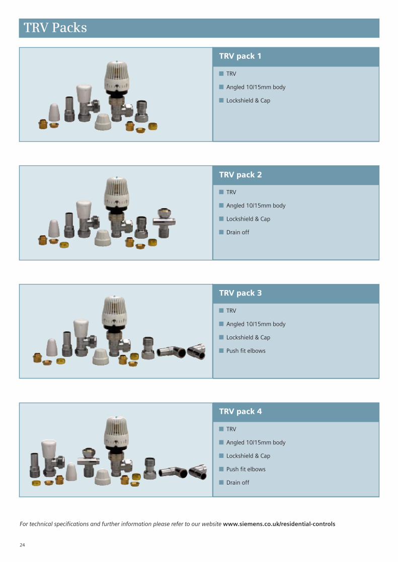
TRV pack 4
■ TRV
■ Angled 10/15mm body
■ Lockshield & Cap
■ Push fit elbows
■ Drain off
TRV pack 3
■ TRV
■ Angled 10/15mm body
■ Lockshield & Cap
■ Push fit elbows
TRV pack 2
■ TRV
■ Angled 10/15mm body
■ Lockshield & Cap
■ Drain off
TRV pack 1
■ TRV
■ Angled 10/15mm body
■ Lockshield & Cap
For technical specifications and further information please refer to our website www.siemens.co.uk/residential-controls
24
TRV Packs

For technical specifications and further information please refer to our website www.siemens.co.uk/residential-controls
25
TRV pack 5
■ TRV
■ Straight 10/15mm body
■ Lockshield & Cap
■ Push fit elbows
■ Drain off
TRV Packs
TRV pack 9
TRV pack 10
■ Drain off valve
TRV pack 11
■ Angled 10/15mm body
■ Lockshield/Wheelhead & Caps
■ Drain off
■ MTN51GB
■ TRV body
■ Lockshield/Wheelhead & Caps
■ Drain off valve

For technical specifications and further information please refer to our website www.siemens.co.uk/residential-controls
26
TRV pack 12
TRV Packs
■ 2 x TRV bodies angled 10/15mm bodies
■ 2 x Lockshield/Wheelhead & Caps
■ Drain off valve

Product Selection Guide Index
Time Controls
At-a-glance 4RWB27 5RWB27Si 5RWB29 5RWB29Si 5RWB2e 6RWB30e 6 RWB1001 7RWB1007 7RWB2001 7RWB2007 7
Room Thermostats
At-a-glance 8RDD100 9RDD100.1 9 RDD100.1DHW 9RAA20LD-GB 10RAA21-GB 10RAA31.16 10RDH10-GB 10RAA11 11
Programmable RoomThermostats
At-a-glance 12RDE100 13RDE100.1 13RDE100.1DHW 13RDJ10-GB 13REV13 14REV17 14REV24 14RAV11.1 15RAA11.7 15
Wireless Thermostats
At-a-glance 16RDH10RF/SET-GB 17RDJ10RF/SET-GB 17RDH10RF/SET/CYL 17RDD100.1RFS 18RDE100.1RFS 18REV24RF/SET 18RDE-MZ6 19RDD100.1RF 19RDE100.1RF 19
Motorised Valves
CZV22 22CZV28 22CMV22 22CMV28 22Demountable Actuator 22
Cylinder, Pipe & FrostThermostats
At-a-glance 20RAM1 21RAM1T 21RAA11 21
Thermostatic Radiator (TRVs)& By-pass valves
MTN51-GB 23Trade TRV 23Trade TRV 2 23BPV22 23TRV Packs 24, 25, 26
For technical specifications and further information please refer to our website www.siemens.co.uk/residential-controls
27
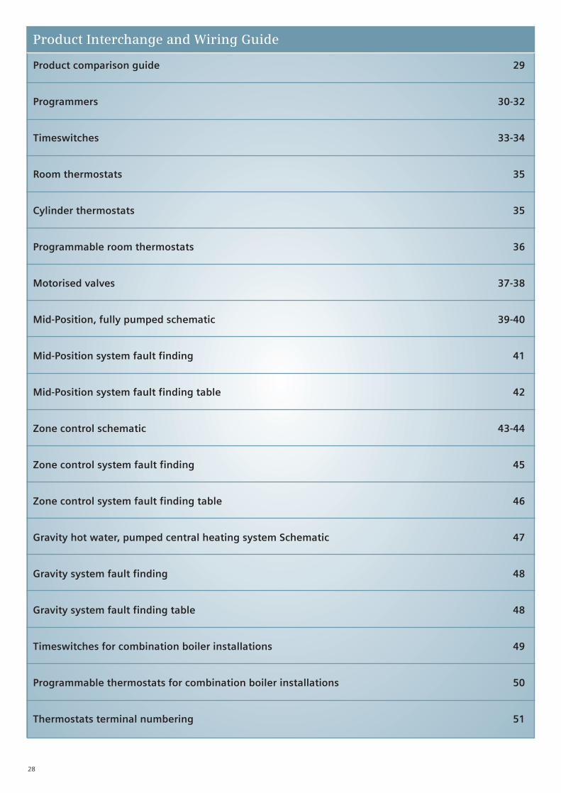
28
Product comparison guide 29
Programmers 30-32
Timeswitches 33-34
Room thermostats 35
Cylinder thermostats 35
Programmable room thermostats 36
Motorised valves 37-38
Mid-Position, fully pumped schematic 39-40
Mid-Position system fault finding 41
Mid-Position system fault finding table 42
Zone control schematic 43-44
Zone control system fault finding 45
Zone control system fault finding table 46
Gravity hot water, pumped central heating system Schematic 47
Gravity system fault finding 48
Gravity system fault finding table 48
Timeswitches for combination boiler installations 49
Programmable thermostats for combination boiler installations 50
Thermostats terminal numbering 51
Product Interchange and Wiring Guide

29
Product Comparison Guide
*To replace a diverter valve with a mid-position valve, replace old brown wire with grey and white together and make the orange safe.
Product Description Siemens Danfoss Randall Drayton Honeywell Horstmann Myson Pegler Potterton Sunvic
Daily electromechanicalprogrammer10 or 16 way
Daily electromechanicaltimeswitch 10 or 16 way
Daily electronicmini-programmer
Daily electronicprogrammer10 or 16 way
Weekday/weekendelectronic programmer
7 day electronicprogrammer
Daily electronictimeswitch
Weekday/weekend electronic timeswitch
7 day electronictimeswitch
Daily programmableroom thermostat
Weekday/weekendprogrammable roomthermostat
7 day programmable room thermostat
Room thermostat
Cylinder thermostat
Mid-position 3-portmotorised valve 22mm
Mid-position 3-portmotorised valve 28mm
2-port motorised zone valve 22mm
2-port motorised zone valve 28mm
Diverter 3-port motorised
TRV angle valve10/15mm
RWB2E
RWB30E
RWB29
RWB29RWB2001
RWB29RWB2007
RWB29RWB2007
RWB27RWB1001
RWB27RWB1007
RWB27RWB1007
REV13
REV24
REV24REV24RF
RAA20
RAM1
*CMV322
*CMV328
CZV222
CZV228
*
MTN51GB
3020P30604033
SET3M
103
102ES102E7SET2E102E5
CP715FP715SET3EFP975
CP715FP715FP975
CP715FP715FP975
TS715SET1E
TS715TS975
TS715TS975
TP4
TPSTP6000TP500
TP700
RET24RET230RMT24
RMT230
ATC
HSV3B 22HSV3
HSV3B 28HS3
HPV228HPV22
HPV288HPV29
HSV3DHS3DB
RAS-C2
400805600SM2
300SM1
-
LP112LP241
Tempus 3Tempus 6
LPS22Tempus 6
LP722Tempus 7
LP111Tempus 1
Tempus 2
LP711Tempus 2
Digistat 2Digistat 4
-
Digistat 3
RTS8
HTS3PTS1
MA1/6793679H
340-0L0
779H340-30L0
679H308-0L1
ZA6/779779H
335-30L0
-
RT111
-
-
ST6200AST9400A
ST699ST9400A
-
ST799ST6400
ST9400C
ST6100
-
ST6100
CM61CM901
-
CM67CM907
T6360
L641
V4073A109
V4073A1088
V4043H1056
V4043H1106
V4044C1288
VT117EVT15
VT200
H425 TiaraH425 Diadem
H425 Coronet
-
Centaurplus C21H21XL
-
Centaurplus C27H27XL
Centaurplus C11H11XL
-
Centaurplus C17H17XL
PRT1AS1
Centaurstat 1
-
Centaurstat 7
HRT1HRT2
HCT1
Z322XL
-
Z222XL
Z228XL
-
Thermoplus XL
-
-
-
MEP2c
MEP2c
MEP2c
MEP1c
MEP1c
MEP1c
-
-
MPRT
MRT1
MCT1
MPE322
MPE328
MPE222
MPE228
MPE322DV
-
TMP2
TMP1
-
TP2
-
-
TP1
-
-
-
-
-
TRT1
TCT1
TMPV22
TMPV28
TZV22
TSZ28
-
-
-
-
-
EP2000
EP2002
EP3002EP6002
EP4000
EP4002
EP5002
-
-
-
PRT2PRT100ST
PTT100
PMV3MSV322
-
PMV2MSV222
-
-
-
MP2
-
-
Simplex 200Select 207XL
Select 207XL
Select 207XL
Simplex 100Select 107XL
Select 107XL
Select 107XL
-
-
TLX6501
TLX2251/2259TLX2356/2357/2358TLX3101/TLX5101TLX920/TLM2802
SA2452
SDV2211SDMV2304
SDMV2320
SZV2212SZMV2305SMV2217
SZV2228SZMV2323
SDV2291
TRV400
30
HW HTG HW HTGMains Off Off On On
Manufacturer Model(s) E N L 1 2 3 4 Wiring
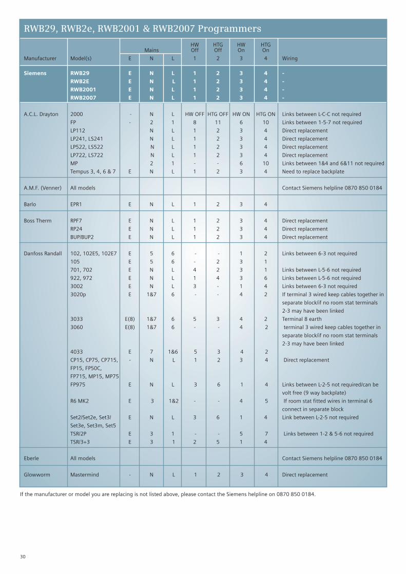
RWB29, RWB2e, RWB2001 & RWB2007 Programmers
Siemens RWB29 E N L 1 2 3 4 -
RWB2E E N L 1 2 3 4 -
RWB2001 E N L 1 2 3 4 -
RWB2007 E N L 1 2 3 4 -
A.C.L. Drayton 2000 - N L HW OFF HTG OFF HW ON HTG ON Links between L-C-C not required
FP - 2 1 8 11 6 10 Links between 1-5-7 not required
LP112 N L 1 2 3 4 Direct replacement
LP241, LS241 N L 1 2 3 4 Direct replacement
LP522, LS522 N L 1 2 3 4 Direct replacement
LP722, LS722 N L 1 2 3 4 Direct replacement
MP 2 1 - - 6 10 Links between 1&4 and 6&11 not required
Tempus 3, 4, 6 & 7 E N L 1 2 3 4 Need to replace backplate
A.M.F. (Venner) All models Contact Siemens helpline 0870 850 0184
Barlo EPR1 E N L 1 2 3 4
Boss Therm RPF7 E N L 1 2 3 4 Direct replacement
RP24 E N L 1 2 3 4 Direct replacement
BUP/BUP2 E N L 1 2 3 4 Direct replacement
Danfoss Randall 102, 102E5, 102E7 E 5 6 - - 1 2 Links between 6-3 not required
105 E 5 6 - 2 3 1
701, 702 E N L 4 2 3 1 Links between L-5-6 not required
922, 972 E N L 1 4 3 6 Links between L-5-6 not required
3002 E N L 3 - 1 4 Links between 6-3 not required
3020p E 1&7 6 - - 4 2 If terminal 3 wired keep cables together in
separate block/if no room stat terminals
2-3 may have been linked
3033 E(8) 1&7 6 5 3 4 2 Terminal 8 earth
3060 E(8) 1&7 6 - - 4 2 terminal 3 wired keep cables together in
separate block/if no room stat terminals
2-3 may have been linked
4033 E 7 1&6 5 3 4 2
CP15, CP75, CP715, - N L 1 2 3 4 Direct replacement
FP15, FP50C,
FP715, MP15, MP75
FP975 E N L 3 6 1 4 Links between L-2-5 not required/can be
volt free (9 way backplate)
R6 MK2 E 3 1&2 - - 4 5 If room stat fitted wires in terminal 6
connect in separate block
Set2/Set2e, Set3/ E N L 3 6 1 4 Link between L-2-5 not required
Set3e, Set3m, Set5
TSR/2P E 3 1 - - 5 7 Links between 1-2 & 5-6 not required
TSR/3+3 E 3 1 2 5 1 4
Eberle All models Contact Siemens helpline 0870 850 0184
Glowworm Mastermind - N L 1 2 3 4 Direct replacement
If the manufacturer or model you are replacing is not listed above, please contact the Siemens helpline on 0870 850 0184.

Siemens RWB29 E N L 1 2 3 4 -
RWB2E E N L 1 2 3 4 -
RWB2001 E N L 1 2 3 4 -
RWB2007 E N L 1 2 3 4 -
Honeywell ST499A - N L - - 6 3 Links between L-2-5 not required/Zone systems only
ST1000 E N L 3 6 1 4 Links between L-2-5 not required
ST6200A 1009 - N L 1 2 3 4 Need to replace backplate
ST6300A 1007 - N L 1 2 3 4 Need to replace backplate
ST6400A 1003 - N L 1 2 3 4 Need to replace backplate
ST6400B 1003 - N L 1 2 3 4 Need to replace backplate
ST6400C 1003 - N L 1 2 3 4 Need to replace backplate
ST6450B 1017 - N L 1 2 3 4 Need to replace backplate
ST699B 1002 - N L 7 4 6 3 Links between L-5-8 not required
ST699C - N L 7 4 6 3 Links between L-5-8 not required
ST7000A 1002 - - L 2 - 3 4 Battery powered will need neutralconnection to operate modern units
ST7100 - N L HW OFF HTG OFF HW ON HTG ON Links between L-3-6 not required
ST7100A 1000 - N L 7 4 8 5 Links between L-3-6 not required
ST799A 1003 - N L 7 4 6 3 Links between L-5-8 not required
ST9400 - N L 1 2 3 4 Change backplate
Horstmann Amethyst 7 & 10 - 2&3 1 4 6 5 7
Amethyst 423 E 2 1 4 6 5 7 Link between 2-3 not required
Centaur Plus C121 E N L 1 2 3 4 Direct replacement
Centaur Plus C21 E N L 1 2 3 4 Direct replacement
Centaur Plus C27 E N L 1 2 3 4 Direct replacement
Centaur Plus C127 E N L 1 2 3 4 Direct replacement
Centaur Plus H21, - N L 3 6 1 4 Links between L-2-5 not required
Centaur Plus H27
Centaur TC1/TC7 - N L 1 2 3 4 Direct replacement
Channel Plus H121/ E N L 3 6 1 4 Links between L-2-5 not required
H21/ H27
Coral 423/424 - 2 1 - - 8 4 Links between 7-8 not required
Diadem 425 E N L 3 6 1 4 Links between L-2-5 not required
Diamond 423, E N L - - 2 4 Links between L-1-3 not required terminal
Diamond 424 5 spare if used keep wires together in
separate block
Tiara 425, 525 E N L 3 6 1 4 Links between L-2-5 not required
IFLO 985627 E N L 1 2 3 4 Direct replacement
Landis & Gyr RWB1 - N L 1 2 3 4 Direct replacement: Note if terminals 1 & 2
have been used these wires should be
removed and placed in separate connectors
RWB2 - N L - - 3 4 Direct replacement
RWB20 - - L 1 2 3 4 Direct replacement, but check neutral
connected and fit if required
RWB40 - N L 1 2 3 4 Direct replacement
RWB102 - N L - - 3 4 Direct replacement (Use 10 mode)
RWB200, RWB252, - N L 1 2 3 4 Direct replacement
RWB270, RWBXP
31
HW HTG HW HTGMains Off Off On On
Manufacturer Model(s) E N L 1 2 3 4 Wiring
RWB29, RWB2e, RWB2001 & RWB2007 Programmers
If the manufacturer or model you are replacing is not listed above, please contact the Siemens helpline on 0870 850 0184.
32
HW HTG HW HTGMains Off Off On On
Manufacturer Model(s) E N L 1 2 3 4 Wiring
RWB29, RWB2e, RWB2001 & RWB2007 Programmers
If the manufacturer or model you are replacing is not listed above, please contact the Siemens helpline on 0870 850 0184.
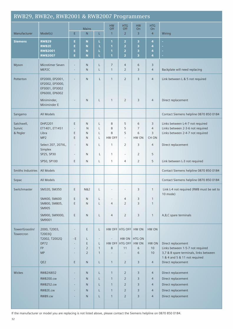
Siemens RWB29 E N L 1 2 3 4 -
RWB2E E N L 1 2 3 4 -
RWB2001 E N L 1 2 3 4 -
RWB2007 E N L 1 2 3 4 -
Myson Microtimer Seven - N L 7 4 6 3
MEP2C - N L 1 2 3 4 Backplate will need replacing
Potterton EP2000, EP2001, - N L 1 2 3 4 Link between L & 5 not required
EP2002, EP3000,
EP3001, EP3002
EP6000, EP6002
Miniminder, - N L 1 2 3 4 Direct replacement
Miniminder E
Sangamo All Models Contact Siemens helpline 0870 850 0184
Satchwell, DHP2201 E N L 8 5 6 3 Links between L-4-7 not required
Sunvic ET1401, ET1451 - N L 8 5 7 4 Links between 2-3-6 not required
& Pegler Libra E N L 8 5 6 3 Links between 2-4-7 not required
MP2 E N L HW OFF - HW ON CH ON
Select 207, 207XL, - N L 1 2 3 4 Direct replacement
Simplex
SP25, SP30 - N L 1 - 2 5
SP50, SP100 E N L 1 4 2 5 Link between L-3 not required
Smiths Industries All Models Contact Siemens helpline 0870 850 0184
Sopac All Models Contact Siemens helpline 0870 850 0184
Switchmaster SM320, SM350 E N&2 L - - 3 1 Link L-4 not required (RWB must be set to
10 mode)
SM400, SM600 E N L - 4 3 1
SM800, SM805, E N L 4 2 3 1
SM905
SM900, SM9000, E N L 4 2 3 1 A,B,C spare terminals
SM9001
Tower/Grasslin/ 2000, T2003, - E L HW OFF HTG OFF HW ON HW ON
Towercron T2003Q
T2002, T2002Q - E L - - HW ON HTG ON
DP72 - E L HW OFF HTG OFF HW ON HW ON Direct replacement
FP - 2 1 8 11 6 10 Links between 1-5-7 not required
MP - 2 1 - - 6 10 3,7 & 8 spare terminals, links between
1 & 4 and 5 & 11 not required
QE2 E N L 1 2 3 4 Direct replacement
Wickes RWB2/6832 - N L 1 2 3 4 Direct replacement
RWB200.cw - N L 1 2 3 4 Direct replacement
RWB252.cw - N L 1 2 3 4 Direct replacement
RWB2E.cw - N L 1 2 3 4 Direct replacement
RWB9.cw - N L 1 2 3 4 Direct replacement

HW HTG HW HTGMains Off Off On On
Manufacturer Model(s) E N L 1 2 3 4 Wiring
RWB27, RWB30e, RWB1001 & RWB1007 Timeswitches
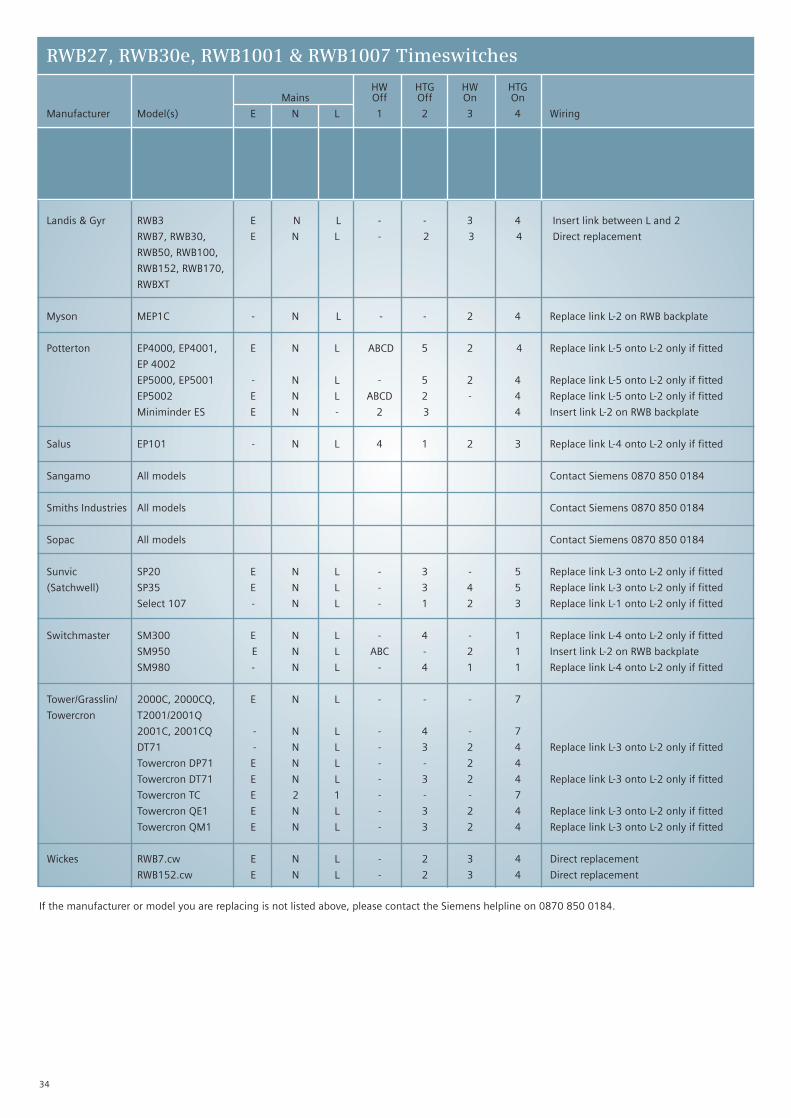
Siemens RWB27 E N L 1 2 3 4 -
RWB30E E N L 1 2 3 4 -
RWB1001 E N L 1 2 3 4 -
RWB1007 E N L 1 2 3 4 -
A.C.L. Drayton LP111, LS111, - N L - 1 2 4 Replace link L-1 onto L-2 only if fitted
Lifestyle, LS711 - N L - 1 2 3 Replace link L-1 onto L-2 only if fitted
LP711 E N L 4 1 2 3 Replace link L-1 onto L-2 only if fitted
Towercron TC - 2 1 - - - 7 Replace link 4-6 onto L-2 only if fitted
Tempus 1 & 2 E N L 4 1 2 3 Replace link L-1 onto L-2 only if fitted
(new models)
Tempus 1 & 2 - N L 4 1 3 2 Replace link L-1 onto L-2 only if fitted
(old models)
SM1 E N L - 1 2 3 Replace link L-1 onto L-2 only if fitted
A.M.F. (Venner) All models Contact Siemens 0870 850 0184
Boss Therm RT7, RT24, BUT/BUT2 E N L - 2 3 4 Direct replacement
RTF7 - N L 1 2 3 4 Direct replacement
Danfoss Randall 103, 103 E5, E 5 6 2 3 - 1 Replace link 6-3 onto L-2 only if fitted
103 E7
151 E 5 6 - 3 2 1 Replace link 6-3 onto L-2 only if fitted
911, 971 E N L - 5 4 6 Replace link L-5 onto L-2 only if fitted
3001 E N L - 5 2 4 Replace link L-5 onto L-2 only if fitted
3020 E 1&7 6 - - - 4 Insert link L-2 on RWB backplate
Set 1 , Set 1e, E N L - 5 6 4 Replace link L-5 onto L-2 only if fitted
Set 4
TS15, TS75 E N L - 1 2 4 Replace link L-1 onto L-2 only if fitted
TS715 - N L 3 1 2 4 Replace link L-1 onto L-2 only if fitted
TS975 E N L 1:2:3 5 6 4 Replace link L-5 onto L-2 only if fitted
TSR/2 E 2&3 L - - - 5 Insert link L-2 on RWB backplate
Eberle All models Contact Siemens 0870 850 0184
Honeywell ST6100A 1001, - N L - 1 2 4 Replace link L-1 onto L-2 only if fitted
ST6100C 1009
ST7000B 1001 E N L - - 2 3 Need to connect Neutral
ST9001 - N L 1 2 3 4 Change backplate
Horstmann 517 E N L - 5 6 4 Replace link L-1 onto L-2 only if fitted
Centaur Plus C11, E N L 1 2 3 4 Replace link L-5 onto L-2 only if fitted
Centaur Plus C17
Centaur Plus H11, E N L - 5 6 4 Replace link L-5 onto L-2 only if fitted
Centaur Plus H17
Centaur SC1, E N L 4 1 2 3 Replace link L-1 onto L-2 only if fitted
Centaur SC7
Channel Plus H11, E N L 1:2:3 5 6 4 Replace link L-5 onto L-2 only if fitted
Channel Plus H17
IFLO 985626 E N L 4 1 2 3 Replace link L-1 onto L-2 only if fitted
33
If the manufacturer or model you are replacing is not listed above, please contact the Siemens helpline on 0870 850 0184.
Siemens RWB27 E N L 1 2 3 4 -
RWB30E E N L 1 2 3 4 -
RWB1001 E N L 1 2 3 4 -
RWB1007 E N L 1 2 3 4 -
Landis & Gyr RWB3 E N L - - 3 4 Insert link between L and 2
RWB7, RWB30, E N L - 2 3 4 Direct replacement
RWB50, RWB100,
RWB152, RWB170,
RWBXT
Myson MEP1C - N L - - 2 4 Replace link L-2 on RWB backplate
Potterton EP4000, EP4001, E N L ABCD 5 2 4 Replace link L-5 onto L-2 only if fitted
EP 4002
EP5000, EP5001 - N L - 5 2 4 Replace link L-5 onto L-2 only if fitted
EP5002 E N L ABCD 2 - 4 Replace link L-5 onto L-2 only if fitted
Miniminder ES E N - 2 3 4 Insert link L-2 on RWB backplate
Salus EP101 - N L 4 1 2 3 Replace link L-4 onto L-2 only if fitted
Sangamo All models Contact Siemens 0870 850 0184
Smiths Industries All models Contact Siemens 0870 850 0184
Sopac All models Contact Siemens 0870 850 0184
Sunvic SP20 E N L - 3 - 5 Replace link L-3 onto L-2 only if fitted
(Satchwell) SP35 E N L - 3 4 5 Replace link L-3 onto L-2 only if fitted
Select 107 - N L - 1 2 3 Replace link L-1 onto L-2 only if fitted
Switchmaster SM300 E N L - 4 - 1 Replace link L-4 onto L-2 only if fitted
SM950 E N L ABC - 2 1 Insert link L-2 on RWB backplate
SM980 - N L - 4 1 1 Replace link L-4 onto L-2 only if fitted
Tower/Grasslin/ 2000C, 2000CQ, E N L - - - 7
Towercron T2001/2001Q
2001C, 2001CQ - N L - 4 - 7
DT71 - N L - 3 2 4 Replace link L-3 onto L-2 only if fitted
Towercron DP71 E N L - - 2 4
Towercron DT71 E N L - 3 2 4 Replace link L-3 onto L-2 only if fitted
Towercron TC E 2 1 - - - 7
Towercron QE1 E N L - 3 2 4 Replace link L-3 onto L-2 only if fitted
Towercron QM1 E N L - 3 2 4 Replace link L-3 onto L-2 only if fitted
Wickes RWB7.cw E N L - 2 3 4 Direct replacement
RWB152.cw E N L - 2 3 4 Direct replacement
34
HW HTG HW HTGMains Off Off On On
Manufacturer Model(s) E N L 1 2 3 4 Wiring
RWB27, RWB30e, RWB1001 & RWB1007 Timeswitches
If the manufacturer or model you are replacing is not listed above, please contact the Siemens helpline on 0870 850 0184.
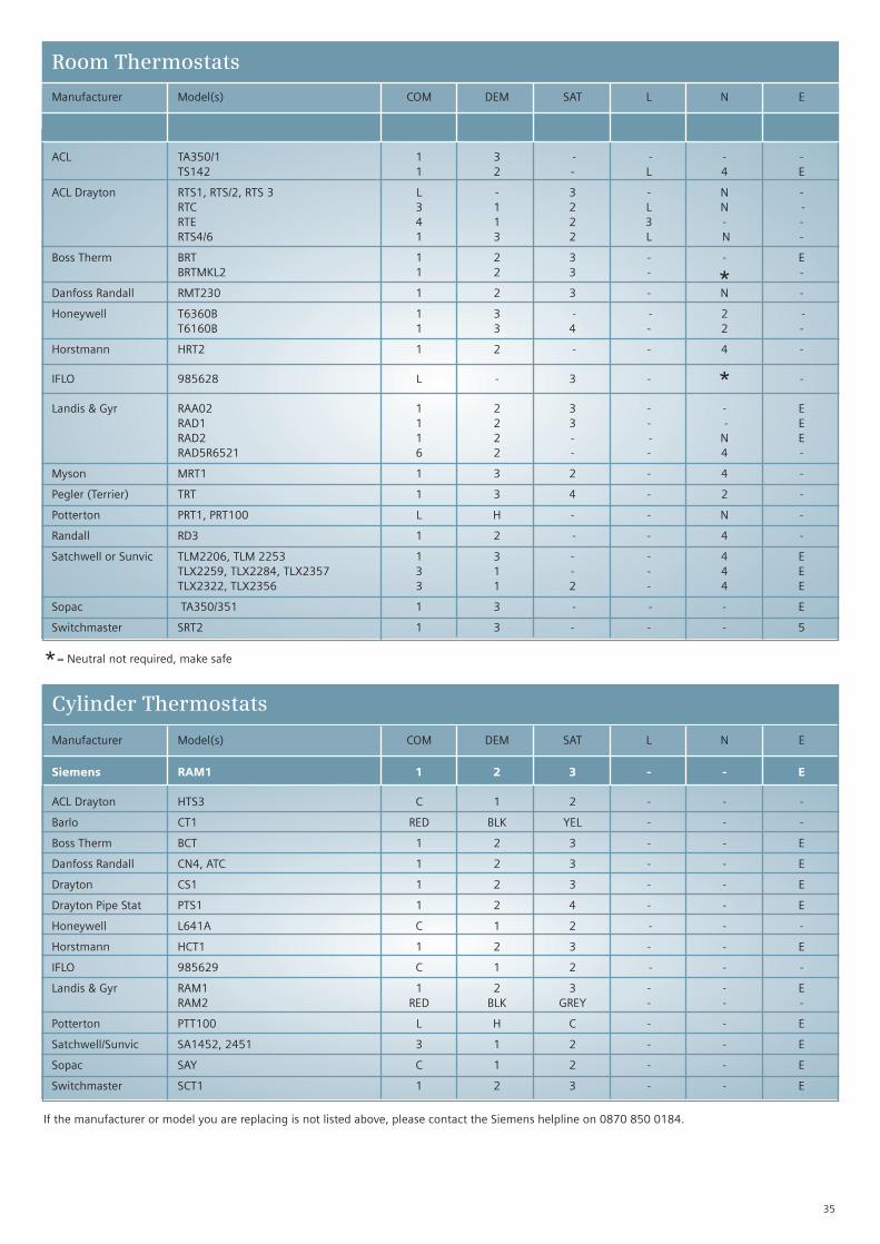
Siemens RAA21GB L Y1 Y2 - - -
ACL TA350/1 1 3 - - - -TS142 1 2 - L 4 E
ACL Drayton RTS1, RTS/2, RTS 3 L - 3 - N -RTC 3 1 2 L N -RTE 4 1 2 3 - -RTS4/6 1 3 2 L N -
Boss Therm BRT 1 2 3 - - EBRTMKL2 1 2 3 - * -
Danfoss Randall RMT230 1 2 3 - N -
Honeywell T6360B 1 3 - - 2 -T6160B 1 3 4 - 2 -
Horstmann HRT2 1 2 - - 4 -
IFLO 985628 L - 3 - * -
Landis & Gyr RAA02 1 2 3 - - ERAD1 1 2 3 - - ERAD2 1 2 - - N ERAD5R6521 6 2 - - 4 -
Myson MRT1 1 3 2 - 4 -
Pegler (Terrier) TRT 1 3 4 - 2 -
Potterton PRT1, PRT100 L H - - N -
Randall RD3 1 2 - - 4 -
Satchwell or Sunvic TLM2206, TLM 2253 1 3 - - 4 ETLX2259, TLX2284, TLX2357 3 1 - - 4 ETLX2322, TLX2356 3 1 2 - 4 E
Sopac TA350/351 1 3 - - - E
Switchmaster SRT2 1 3 - - - 5
35
Manufacturer Model(s) COM DEM SAT L N E
Room Thermostats
Manufacturer Model(s) COM DEM SAT L N E
Cylinder Thermostats
Siemens RAM1 1 2 3 - - E
ACL Drayton HTS3 C 1 2 - - -
Barlo CT1 RED BLK YEL - - -
Boss Therm BCT 1 2 3 - - E
Danfoss Randall CN4, ATC 1 2 3 - - E
Drayton CS1 1 2 3 - - E
Drayton Pipe Stat PTS1 1 2 4 - - E
Honeywell L641A C 1 2 - - -
Horstmann HCT1 1 2 3 - - E
IFLO 985629 C 1 2 - - -
Landis & Gyr RAM1 1 2 3 - - ERAM2 RED BLK GREY - - -
Potterton PTT100 L H C - - E
Satchwell/Sunvic SA1452, 2451 3 1 2 - - E
Sopac SAY C 1 2 - - E
Switchmaster SCT1 1 2 3 - - E
If the manufacturer or model you are replacing is not listed above, please contact the Siemens helpline on 0870 850 0184.
*= Neutral not required, make safe

Siemens REV13 L L1 L2 - - -
REV11/REV12 L L1 - - - -
REV10 Q1 Q2 - - - -
RDJ10 LX L1 L2 - - -
RDJ10RF LX L1 L2 L N -
RDE100 Q11 Q14 Q12 L N -
RDE100.1 Q11 Q14 Q12 - - -
RDE100.1RFS Q11 Q14 Q12 L N -
ACL Drayton PT271 1 3 2 - - -
Digistat 2/4 1 3 2 - - -
Digistat +2 C ON OFF - - -
Digistat +2RF C 3 2 - - -
Boss Therm BPS242/BPS242RF LX L1 L2 - - -
Danfoss Randall TP2 1 3 2 - - -
TP4 1 3 2 - - -
Honeywell CM61 A B C - - -
CM6901 A B C - - -
Horstmann Centaurstat 1 2 3 - - -
IFLO 263942 C ON OFF - - -
263939 1 3 2 - - -
Sunvic TLX6501 1 2 3 - - -
36
Manufacturer Model(s) COM DEM SAT L N E
Daily programmable thermostat
Programmable Room Thermostats
Manufacturer Model(s) COM DEM SAT L N E
Weekday/weekend programmable thermostat
Manufacturer Model(s) COM DEM SAT L N E
Siemens REV23 L L1 L2 - - -
REV23RF L L1 L2 - - -
REV24 L L1 L2 - - -
REV24RF LX L1 L2 L N -
ACL Drayton Digistat 3 1 3 2 - - -
Digistat RF 3 1 3 2 L N -
Danfoss Randall TP75 3 5 6 - - -
TP700 1 2 3 - - -
TP75RF 2 3 4 L N -
TP7000RF 1 2 3 L N -
Honeywell CM67 A B C - - -
CM67RF A B C L N -
CM901 A B C - - -
Horstmann Centaurstat 7 1 2 3 - - -
If the manufacturer or model you are replacing is not listed above, please contact the Siemens helpline on 0870 850 0184.
Siemens REV17 L L1 L2 - - -
REV21 Q1 Q2 Q3 - - -
REV22 L L1 L2 - - -
REV23 L L1 L2 - - -
ACL Drayton Digistat 3 1 3 2 - - -
ACL Lifestyle CT171 1 3 2 - - -
Danfoss Randall TP3 1 3 2 - - -
TP5 1 3 2 - - -
TP75 3 5 6 - - -
TP5000 B C A - - -
Honeywell CM67 A B C - - -
Horstmann Centaurstat 7 1 2 3 - - -
7 Day programmable thermostat

37
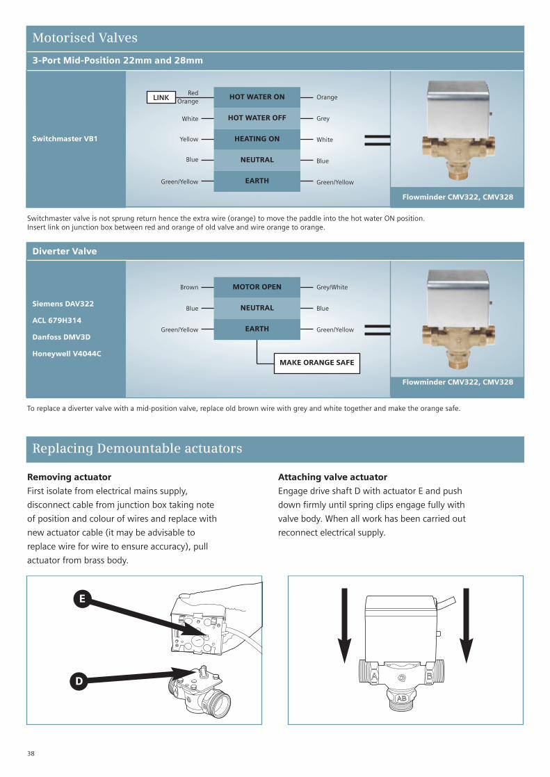
3-Port Mid-Position 22mm and 28mm
Motorised Valves
Siemens/L&S MA-V322
ACL 679H340
Danfoss DMV3M
Drayton Flowshare
Honeywell V4073A
Tower MP3
Landis & Gyr SK3
Potterton PMV3
Randell HSA3
Sunvic SD1701
HOT WATER ON
HOT WATER OFF
HEATING ON
NEUTRAL
EARTH
Orange
Grey
White or Brown
Blue
Green/Yellow
Orange
Grey
White
Blue
Green/Yellow
HOT WATER ON
HOT WATER OFF
HEATING ON
NEUTRAL
EARTH
Orange
Grey
White or Brown
Blue
Green/Yellow
Orange
Grey
White
Blue
Green/Yellow
Flowminder CMV322, CMV328
2-Port Zone22mm and 28mm
ACL 6799H308
Danfoss DMV2C
Honeywell V4043H
Landis & Gyr ZA-V222
Tower MV2
ACL 679H308
Landis & Gyr SK2
Potterton PMV2
Randell HP2
Sunvic SZ1326
PERMANENT LIVE
SWITCHED LIVE
MOTOR OPEN
NEUTRAL
EARTH
Grey
Orange
Brown
Blue
Green/Yellow
Grey
Orange
Brown
Blue
Green/Yellow
PERMANENT LIVE
SWITCHED LIVE
MOTOR OPEN
NEUTRAL
EARTH
Grey
Orange
Brown
Blue
Grey
Orange
Brown
Blue
Green/Yellow
Zoneminder CZV322, CZV328
In the event of motor failure all CMV and CZV products can be replaced without drain down using DVA actuators (see next page)
38
3-Port Mid-Position 22mm and 28mm
Motorised Valves
Switchmaster VB1
HOT WATER ON
HOT WATER OFF
HEATING ON
NEUTRAL
EARTH
RedOrange
White
Yellow
Blue
Green/Yellow
Orange
Grey
White
Blue
Green/Yellow
Flowminder CMV322, CMV328
LINK
Switchmaster valve is not sprung return hence the extra wire (orange) to move the paddle into the hot water ON position.Insert link on junction box between red and orange of old valve and wire orange to orange.
Diverter Valve
Siemens DAV322
ACL 679H314
Danfoss DMV3D
Honeywell V4044C
MOTOR OPEN
NEUTRAL
EARTH
Brown
Blue
Green/Yellow
Grey/White
Blue
Green/Yellow
Flowminder CMV322, CMV328
To replace a diverter valve with a mid-position valve, replace old brown wire with grey and white together and make the orange safe.
MAKE ORANGE SAFE
Replacing Demountable actuators
E
D
Removing actuator
First isolate from electrical mains supply,
disconnect cable from junction box taking note
of position and colour of wires and replace with
new actuator cable (it may be advisable to
replace wire for wire to ensure accuracy), pull
actuator from brass body.
Attaching valve actuator
Engage drive shaft D with actuator E and push
down firmly until spring clips engage fully with
valve body. When all work has been carried out
reconnect electrical supply.
7
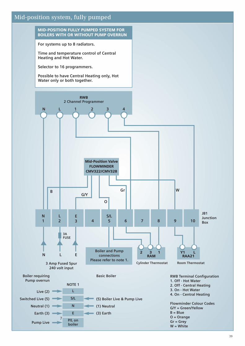
Mid-position system, fully pumped
N L 1 2 3 4
N1
L2
E3 4
S/L5 6 7 8 9 10
JB1JunctionBox
Room ThermostatCylinder Thermostat
3AFUSE
N L E
RWB2 Channel Programmer
Mid-Position ValveFLOWMINDER
CMV322/CMV328
Boiler and Pumpconnections
Please refer to note 1.3 Amp Fused Spur
240 volt input
BG/Y
Gr W
O
2 3 1 RAM
Y1 L RAA21
RWB Terminal Configuration1. Off - Hot Water2. Off - Central Heating3. On - Hot Water4. On - Central Heating
Flowminder Colour CodesG/Y = Green/YellowB = BlueO = OrangeGr = GreyW = White
NOTE 1
L
S/L
N
E
P/L onboiler
Live (2)
Switched Live (5)
Neutral (1)
Earth (3)
Pump Live
(5) Boiler Live & Pump Live
(1) Neutral
(3) Earth
Boiler requiringPump overrun
Basic Boiler
MID-POSITION FULLY PUMPED SYSTEM FORBOILERS WITH OR WITHOUT PUMP OVERRUN
For systems up to 8 radiators.
Time and temperature control of CentralHeating and Hot Water.
Selector to 16 programmers.
Possible to have Central Heating only, HotWater only or both together.
39
40
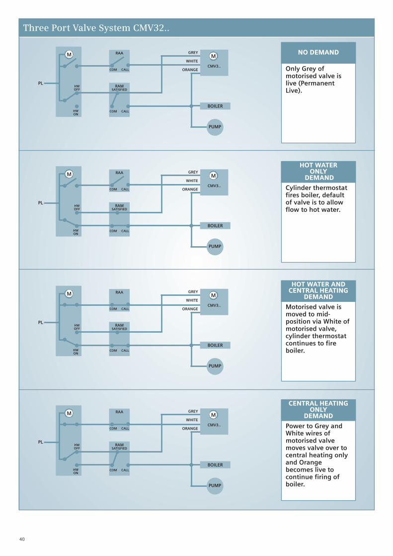
Three Port Valve System CMV32..
NO DEMAND
Only Grey ofmotorised valve islive (PermanentLive).
HOT WATERONLY
DEMAND
Cylinder thermostatfires boiler, defaultof valve is to allowflow to hot water.
HOT WATER ANDCENTRAL HEATING
DEMAND
Motorised valve ismoved to mid-position via White ofmotorised valve,cylinder thermostatcontinues to fireboiler.
CENTRAL HEATING ONLY
DEMAND
Power to Grey andWhite wires ofmotorised valvemoves valve over tocentral heating onlyand Orangebecomes live tocontinue firing ofboiler.
M M
CMV3..
BOILER
PUMP
COM CALL
COM CALL
HWOFF
HWON
PL
RAA
RAMSATISFIED
GREY
WHITE
ORANGE
M M
CMV3..
BOILER
PUMP
COM CALL
COM CALL
HWOFF
HWON
PL
RAA
RAMSATISFIED
GREY
WHITE
ORANGE
M
BOILER
PUMP
COM CALL
COM CALL
HWOFF
HWON
PL
RAA
RAMSATISFIED
GREY
WHITE
ORANGE
M
CMV3..
M
BOILER
PUMP
COM CALL
COM CALL
HWOFF
HWON
PL
RAA
RAMSATISFIED
GREY
WHITE
ORANGE
M
CMV3..

41
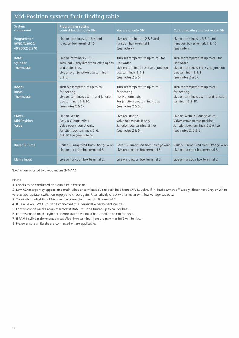
Mid-Position system fault finding
The fault finding table enables quick electrical checksto be carried out on installed Mid-Position systems. Itwill help in commissioning and pinpointing the sourceof any electrical problems.
Only suspect faulty components after you havechecked the wiring and you are satisfied that thewiring is correct.
Fault Finding Identification
ProgrammerCheck links are in place (where relevant).Check mains supply to terminal L.
Suspect programmera. After you have checked that the
switching times are correctly set (referto user manual), and the programmertime is set within a switching period.
b. If live does not appear at JB terminal 8when HW only is selected ON, ONCEor ALL DAY
c. If live does not appear at JB terminal10 when CH only is selected ON,ONCE or ALL DAY.
To carry out the following checks setprogrammer HW and CH to 24h, ON orCONTINUOUS.
RAM1 Cylinder ThermostatCheck wiring against relevant wiringdiagram, disconnect mains supply,remove wire from terminals 2 and 3 andmake safe separately. Re-connect supply.Check mains supply is live to terminal 1.
Suspect RAM1a. If terminal 2 is not live when calling
for heat turn thermostat to maximum.b. If terminal 3 is not live when satisfied
turn thermostat to minimum.
Room ThermostatCheck wiring against relevant wiringdiagram, disconnect mains supply,remove wire from terminal Y1 and makesafe, reconnect supply. Check mainssupply to terminal L.
Suspect RAA21a. If terminal Y1 is not live when calling
for heat turn thermostat to maximum.b. If terminal Y2 is not live when satisfied
turn thermostat to minimum.
CMV3.. Mid-Position ValveSuspect valve if, in any of the followingchecks the valve does not operate asdescribed. Switch programmer to ONposition.
Check A Heating OnlyDisconnect mains supply. DisconnectGrey and White wires from JB terminals 6& 9. Connect Grey and White wires to JBterminal 2.
Reconnect mains supply, valve shouldopen to port A. The boiler and pump willfire and the pipe from port A will getprogressively warmer.
Check B Hot Water OnlyDisconnect mains supply. Valve willreturn to open port B and close port A.Disconnect White wire and make safe i.e.use spare JB terminal 7. Connect boilerand pump wire from JB terminal 5 to JBterminal 2. Switch on mains supply. Theboiler and pump will fire and the pipefrom port B will get progressivelywarmer.
Check C Heating and Hot WaterDisconnect mains supply. Remove Greywire from JB terminal 2 and make safe.Connect White wire to JB terminal 2.Switch on mains supply.
The valve will motor to the mid-positionand stop. Both ports A & B are open. Theboiler and pump will fire and the pipesfrom ports A & B will get progressivelywarmer.
Disconnect mains supply. ReconnectWhite wire to JB terminal 9, Grey wire toJB terminal 6 and the boiler and pumplive to JB terminal 5.
42
Programmer settingcentral heating only ON Hot water only ON Central heating and hot water ON
Mid-Position system fault finding table
Systemcomponent
Programmer Live on terminals L, 1 & 4 and Live on terminals L, 2 & 3 and Live on terminals L, 3 & 4 and
RWB2/9/20/29/ junction box terminal 10. junction box terminal 8 junction box terminals 8 & 10
40/200/252/270 (see note 7). (see note 7).
RAM1 Live on terminals 2 & 3. Turn set temperature up to call for Turn set temperature up to call for
Cylinder Terminal 2 only live when valve opens Hot Water. Hot Water.
Thermostat and boiler fires. Live on terminals 1 & 2 and junction Live on terminals 1 & 2 and junction
Live also on junction box terminals box terminals 5 & 8 box terminals 5 & 8
5 & 6. (see notes 2 & 6). (see notes 2 & 6).
RAA21 Turn set temperature up to call Turn set temperature up to call Turn set temperature up to call
Room for heating. for heating. for heating.
Thermostat Live on terminals L & Y1 and junction No live terminals. Live on terminals L & Y1 and junction
box terminals 9 & 10. For junction box terminals box terminals 9 & 10.
(see notes 2 & 5). (see notes 2 & 5).
CMV3.. Live on White, Live on Orange. Live on White & Orange wires.
Mid-Position Grey & Orange wires. Valve opens port B only. Valves move to mid-position.
Valve Valve opens port A only. Junction box terminal 5 live Junction box terminals 5 & 9 live
Junction box terminals 5, 6, (see notes 2 & 6). (see notes 2, 5 & 6).
9 & 10 live (see note 5).
Boiler & Pump Boiler & Pump fired from Orange wire. Boiler & Pump fired from Orange wire. Boiler & Pump fired from Orange wire.
Live on junction box terminal 5. Live on junction box terminal 5. Live on junction box terminal 5.
Mains Input Live on junction box terminal 2. Live on junction box terminal 2. Live on junction box terminal 2.
‘Live’ when referred to above means 240V AC.
Notes
1. Checks to be conducted by a qualified electrician.
2. Low AC voltage may appear on certain wires or terminals due to back feed from CMV3.. valve. If in doubt switch off supply, disconnect Grey or White
wire as appropriate, switch on supply and check again. Alternatively check with a meter with low voltage capacity.
3. Terminals marked E on RAM must be connected to earth, JB terminal 3.
4. Blue wire on CMV3.. must be connected to JB terminal 4 permanent neutral.
5. For this condition the room thermostat RAA.. must be turned up to call for heat.
6. For this condition the cylinder thermostat RAM1 must be turned up to call for heat.
7. If RAM1 cylinder thermostat is satisfied then terminal 1 on programmer RWB will be live.
8. Please ensure all Earths are connected where applicable.

43
7
Zone Control system
N L 1 2 3 4
N1
L2
E3
N4 7 9 10
JB1JunctionBox
Room ThermostatCylinder Thermostat
3AFUSE
N L E
RWB2 Channel Programmer
ZONEMINDERCZV222
ZONEMINDERCZV222
Boiler and Pumpconnections
Please refer to note 1.3 Amp Fused Spur
240 volt input
G/Y
1 2 RAM
Y1 L RAA21
RWB Terminal Configuration1. Off - Hot Water2. Off - Central Heating3. On - Hot Water4. On - Central Heating
Zoneminder Colour CodesG/Y = Green/YellowB = BlueO = OrangeGr = GreyBr = Brown
NOTE 1
L
S/L
N
E
P/L onboiler
Live (2)
Switched Live (5)
Neutral (1)
Earth (3)
Pump Live
(5) Boiler Live & Pump Live
(1) Neutral
(3) Earth
Boiler requiringPump overrun
Basic Boiler
ZONE CONTROL SYSTEM FOR BOILERS WITHOR WITHOUT PUMP OVERRUN
Increased flexibility over mid-position system.
Able to have several CH and HW controlledindependently.
Time and temperature control of CentralHeating and Hot Water.
Possible to have Central Heating only, HotWater only or both together.
G/Y
8S/L5 6
B B
O
O
Gr Gr
Br
Br
44
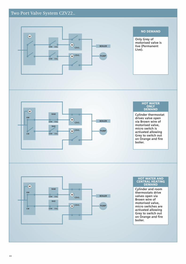
Two Port Valve System CZV22..
M
M
M
CZV2..
CZV2..
BOILER
PUMPCOM CALL
COM CALL
M
M
M
CZV2..
CZV2..
BOILER
PUMPCOM CALL
COM CALL
RAM
RAD
HW
CW
M
M
M
CZV2..
CZV2..
BOILER
PUMPCOM CALL
COM CALL
RAM
RAD
HW
CW
NO DEMAND
Only Grey ofmotorised valve islive (PermanentLive).
HOT WATERONLY
DEMAND
Cylinder thermostatdrives valve openvia Brown wire ofmotorised valve,micro switch isactivated allowingGrey to switch outon Orange and fireboiler.
HOT WATER ANDCENTRAL HEATING
DEMAND
Cylinder and roomthermostats drivevalves open viaBrown wire ofmotorised valve,micro switches areactivated allowingGrey to switch outon Orange and fireboiler.
45
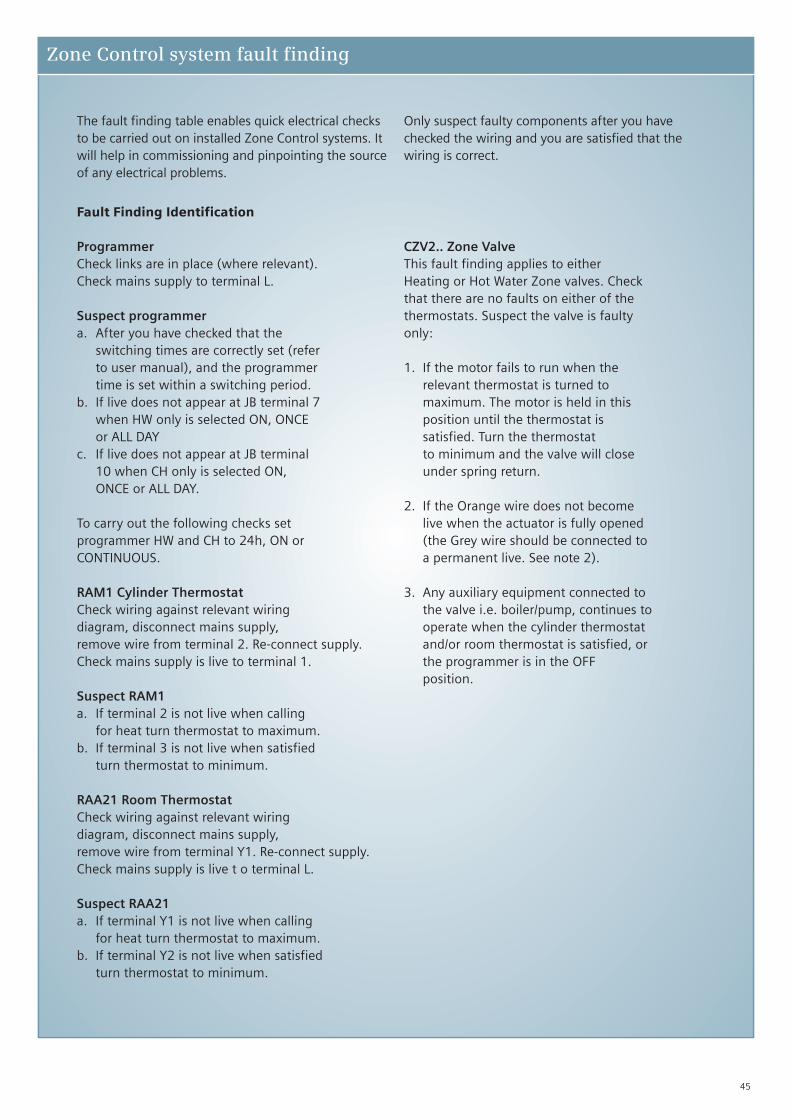
The fault finding table enables quick electrical checksto be carried out on installed Zone Control systems. Itwill help in commissioning and pinpointing the sourceof any electrical problems.
Only suspect faulty components after you havechecked the wiring and you are satisfied that thewiring is correct.
Fault Finding Identification
ProgrammerCheck links are in place (where relevant).Check mains supply to terminal L.
Suspect programmera. After you have checked that the
switching times are correctly set (referto user manual), and the programmertime is set within a switching period.
b. If live does not appear at JB terminal 7when HW only is selected ON, ONCEor ALL DAY
c. If live does not appear at JB terminal10 when CH only is selected ON,ONCE or ALL DAY.
To carry out the following checks setprogrammer HW and CH to 24h, ON orCONTINUOUS.
RAM1 Cylinder ThermostatCheck wiring against relevant wiringdiagram, disconnect mains supply,remove wire from terminal 2. Re-connect supply.Check mains supply is live to terminal 1.
Suspect RAM1a. If terminal 2 is not live when calling
for heat turn thermostat to maximum.b. If terminal 3 is not live when satisfied
turn thermostat to minimum.
RAA21 Room ThermostatCheck wiring against relevant wiringdiagram, disconnect mains supply,remove wire from terminal Y1. Re-connect supply. Check mains supply is live t o terminal L.
Suspect RAA21a. If terminal Y1 is not live when calling
for heat turn thermostat to maximum.b. If terminal Y2 is not live when satisfied
turn thermostat to minimum.
CZV2.. Zone ValveThis fault finding applies to eitherHeating or Hot Water Zone valves. Checkthat there are no faults on either of thethermostats. Suspect the valve is faultyonly:
1. If the motor fails to run when therelevant thermostat is turned tomaximum. The motor is held in thisposition until the thermostat issatisfied. Turn the thermostatto minimum and the valve will closeunder spring return.
2. If the Orange wire does not becomelive when the actuator is fully opened(the Grey wire should be connected toa permanent live. See note 2).
3. Any auxiliary equipment connected tothe valve i.e. boiler/pump, continues tooperate when the cylinder thermostatand/or room thermostat is satisfied, orthe programmer is in the OFFposition.
Zone Control system fault finding

46
Programmer settingcentral heating only ON Hot water only ON Central heating and hot water ON
Zone Control system fault finding table
Systemcomponent
Programmer Live on both terminals L & 4 and Live on both terminals L & 3 and Live on both terminals L, 3 & 4 and
junction box terminal 10. junction box terminal 7. junction box terminals 7 & 10.
RAM1 No live terminals on cylinder Turn set temperature up to call for Turn set temperature up to call for
Cylinder thermostat. Hot Water. Hot Water.
Thermostat Live on terminals 1 & 2 and junction Live on terminals 1 & 2 and junction
box terminals 7 & 8. box terminals 7 & 8.
RAA21 Turn set temperature up to call No live terminals on room thermostat. Turn set temperature up to call
Room for heating. for heating.
Thermostat Live on terminals L & Y1 and junction Live on terminals L & Y1 and junction
box terminals 9 & 10. box terminals 9 & 10.
CZV2.. Live on Brown, Orange & Grey wires Live on Orange & Grey wires & junction Live on Brown, Orange & Grey wires
Heating Valve and junction box terminals 5, 6 & 9. box terminals 5 & 6 (see note 5). and junction box terminals 5, 6 & 9.
CZV2.. Live on Orange & Grey wires & Live on Brown, Orange & Grey wires Live on Brown, Orange & Grey wires
Hot Water Valve junction box terminals 5 & 6 and junction box terminals 5,6 & 8. and junction box terminals 5, 6 & 8.
(see note 5).
Boiler & Pump Boiler & Pump fired from Orange wire. Boiler & Pump fired from Orange wire. Boiler & Pump fired from Orange wire.
Live on junction box terminal 5. Live on junction box terminal 5. Live on junction box terminal 5.
Mains Input Live on junction box terminals 2 & 6. Live on junction box terminal 2 & 6. Live on junction box terminals 2 & 6.
‘Live’ when referred to above means 240V AC.
Notes
1. Checks to be conducted by a qualified electrician.
2. Grey wire on both heating and hot water valves must be connected to a permanent live – JB terminal 6. Insert link from terminal 2 to terminal 6.
3. Blue wire on both heating and hot water valves must be connected to a permanent neutral – JB terminal 4.
4. Terminals marked E on RAM must be connected to earth – JB terminal 3.
5. Orange wire only becomes live when either 2 port valve has opened.
6. Please ensure all Earths are connected where applicable.
47
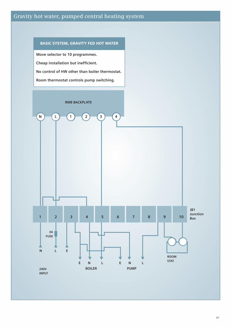
Gravity hot water, pumped central heating system
N L 1 2 3 4
1 2 3 4 5 6 7 8 9 10
JB1JunctionBox
ROOMSTAT
3AFUSE
240VINPUT
E N L
PUMP
E N L
BOILER
N L E
RWB BACKPLATE
BASIC SYSTEM, GRAVITY FED HOT WATER
Move selector to 10 programmes.
Cheap installation but inefficient.
No control of HW other than boiler thermostat.
Room thermostat controls pump switching.
48
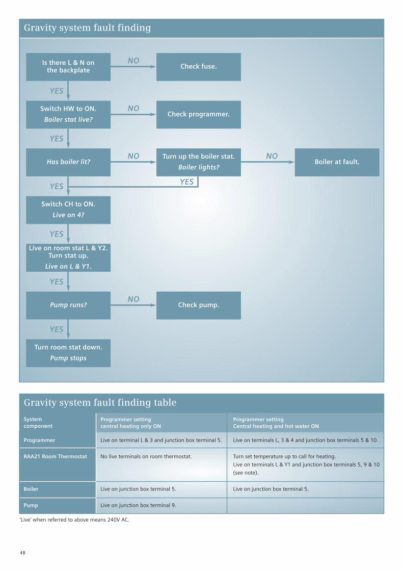
Gravity system fault finding
Is there L & N onthe backplate
YES
Check fuse.
Switch HW to ON.
Boiler stat live?
YES
Has boiler lit?
YES
Switch CH to ON.
Live on 4?
YES
Live on room stat L & Y2.Turn stat up.
Live on L & Y1.
YES
Pump runs?
YES
Turn room stat down.
Pump stops
NO
Check programmer.NO
Turn up the boiler stat.
Boiler lights?
NO
Check pump.NO
Boiler at fault.NO
YES
Programmer setting Programmer settingcentral heating only ON Central heating and hot water ON
Gravity system fault finding table
Systemcomponent
Programmer Live on terminal L & 3 and junction box terminal 5. Live on terminals L, 3 & 4 and junction box terminals 5 & 10.
RAA21 Room Thermostat No live terminals on room thermostat. Turn set temperature up to call for heating.
Live on terminals L & Y1 and junction box terminals 5, 9 & 10
(see note).
Boiler Live on junction box terminal 5. Live on junction box terminal 5.
Pump Live on junction box terminal 9.
‘Live’ when referred to above means 240V AC.

For technical specifications and further information please refer to our website www.siemens.co.uk/residential-controls
49
Timeswitches for combination boilers
Manufacturer Model Mains Mains Not used Common Off On
Siemens RWB27 N L 1 2 3 4
RWB30E N L 1 2 3 4
RWB1001 N L 1 2 3 4
RWB1007 N L 1 2 3 4
Baxi Maxflow FS N L - 1 - 2
Maxflow WM N L - 1 - 2
Ferroli Optimax 255, 25C, 240V N L - 4 - 5
F23, F24 N L - 3 - 4
Glowworm XTRAFAST 96 N L - *E - *E
XTRAFAST 120 N L - *E - *E
XTRAMAX 24Ci, 30Ci, 35Ci, N L - *E - *E24Cxi, 30Cxi, 38Cxi, 18Si, 30Si(Note remove link E-E)
Halstead Ace, Ace High, Finest, Platinum N L - L1 - L3
Ideal C80, 95FF N L - R1 - R2
Response 80, 100, 120 N L - R1 - R*
Potterton Performance range N L - 1 - 2
Saunier Duval Classic range (Remove link *-*) N L - * - *
Vaillant N L - 3 - 4
Worcester 24, 24i Junior N L - LS - LR
Cdi 24, 28, Si, R25HE, R30HE N L - LS - LR
RWB Timeswitches terminals
Manufacturer Model Mains Mains Not used Common Off On
Boiler terminals *These two terminals are numbered as below by the boiler manufacturer
If boiler you are using is not shown above please refer to the manufacturers instructions

50
Programmable thermostats for combination boilers
Manufacturer Model Common Off On
Siemens REV13 L - L1
REV17 L - L1
REV24 L - L1
RDJ10 Lx - L1
RDD10.1 Q11 - Q14
Baxi Maxflow FS 1 - 2
Maxflow WM 1 - 2
Ferroli Optimax 255, 25C, 240V 4 - 5
F23, F24 3 - 4
Glowworm XTRAFAST 96 *E - *E
XTRAFAST 120 *E - *E
XTRAMAX 24Ci, 30Ci, 35Ci, *E - *E24Cxi, 30Cxi, 38Cxi, 18Si, 30Si(Note remove link E-E)
Halstead Ace, Ace High, Finest, Platinum L1 - L3
Ideal C80, 95FF R1 - R2
Response 80, 100, 120 R1 - R*
Potterton Performance range 1 - 2
Saunier Duval Classic range (Remove link *-*) * - *
Vaillant 3 - 4
Worcester 24, 24i Junior LS - LR
Cdi 24, 28, Si, R25HE, R30HE LS - LR
Programmable thermostat terminals
Manufacturer Model Common* Off On*
Boiler terminals *These two terminals are numbered as below by the boiler manufacturer
If boiler you are using is not shown above please refer to the manufacturers instructions

51
Thermostat terminal numbering
Type Model COM DEM SAT L N E
Standard RAA02.1N 1 2 3 - - E
RAA02.16N (Neon) 1 2 3 - 6 E
RAA10 (Tamperproof) L Y1 Y2 - - -
RAA20 L Y1 Y2 - - -
RAD1F (Frost) 1 2 3 - - E
RAA21 L Y1 Y2
RAA11 (Frost/Tamperproof) L Y1 Y2
Digital Display RDD10 (Mains operated) Q11 Q14 Q12 L N -
RDD10.1 (Battery operated) Q11 Q14 Q12 - - -
RDD100 (Mains operated) Q11 Q14 Q12 L N -
RDD100.1 (Battery operated) Q11 Q14 Q12 - - -
Programmable Analog RAV11 (Battery operated) L L1 L2 - - -
Programmable Digital REV12 L L1 - - - -
REV22 L L1 L2 - - -
REV23 L L1 L2 - - -
REV23RF LX L1 L2 L N -
RDE100 (mains operated) Q11 Q14 Q12 L N -
RDE100.1 (Battery operated) Q11 Q14 Q12 - - -
RDE200.1 (Battery operated) Q11 Q14 Q12 - - -
Daily Programmable REV13 L L1 L2 - - -
RDJ10 LX L1 L2 - - -
RDJ10RF L L1 L2 L N -
Weekday/weekendProgrammable
REV17 L L1 L2 - - -
7 Day Programmable REV24 L L1 L2 - - -
REV24RF LX L1 L2 L N -
Digital RDH10 LX L1 L2 - - -

The information in this document contains general descriptions of technical options available,which do not always have to be present in individual cases. The required features should thereforebe specified in each individual case at the time of closing the contract.
© Siemens plc • Order no. Product Selection Guide V1 • Printed in the UK.
www.siemens.co.uk/residential-controls
Siemens plcBuilding Technologies DivisionSiemens Heating ControlsSir William Siemens SquareFrimleyCamberleySurreyGU16 8QD
Technical helpline: 0870 850 0184
e-mail: [email protected]
Our world is undergoing changes that force us to thinkin new ways: demographic change, urbanisation, globalwarming and resource shortages. Maximum efficiencyhas top priority – and not only where energy is concerned.In addition, we need to increase comfort for the well beingof users. Also, our need for safety and security is constantlygrowing. For our customers, success is defined by howwell they manage these challenges.
Siemens has the answers.