siemens power technologies international - uwig.org · session 26: wind & pv modeling in pss®e...
TRANSCRIPT

Answers for infrastructure and cities.Restricted © Siemens AG 2013 All rights reserved.September 2002
Session 26: Wind & PV Modeling in PSS®E UVIG Short Course; Portland, OR; June 2014
Ross AltmanSiemens PTI
Siemens Power Technologies International
Restricted © Siemens AG 2013 All rights reserved.
Discussion Outline
• Representing wind turbines & PV in PSS®E Power Flow
• PSS®E Dynamic Simulation models of wind turbines & PV systems
• 2nd Generation Generic wind turbine & PV models in PSS®E
• Test results for 2nd Generation wind models - Siemens 2.3 MW wind machines
• Recent development s- Plant controller for multi-unit application
• Wind and PV modeling issues and considerations
• Summary
Page 2
Restricted © Siemens AG 2013 All rights reserved.
Represention of Wind Turbine in PSS®E Power Flow
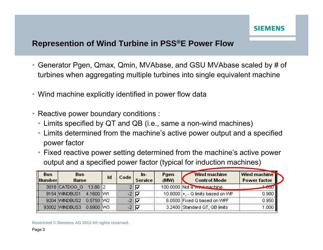
• Generator Pgen, Qmax, Qmin, MVAbase, and GSU MVAbase scaled by # of turbines when aggregating multiple turbines into single equivalent machine
• Wind machine explicitly identified in power flow data
• Reactive power boundary conditions :• Limits specified by QT and QB (i.e., same a non-wind machines)• Limits determined from the machine’s active power output and a specified
power factor• Fixed reactive power setting determined from the machine’s active power
output and a specified power factor (typical for induction machines)
Page 3

Restricted © Siemens AG 2013 All rights reserved.
Representation of Wind Turbine in PSS®E Dynamic Simulation
• User prepares dynamic raw data file (“dyr” file) by following example in modeling package documentation
• Two distinct groups of Wind Models:
Vendor specific models: are provided as user-written models. To represent these machines in power flow, typically designate the machines as ‘Not a Wind Machine’ in the PSS ® E power flow generator data record.
Models can be downloaded from:http://w3.usa.siemens.com/smartgrid/us/en/transmission-
grid/products/grid-analysis-tools/transmission-system-planning/Pages/transmission-system-planning.aspx?tabcardname=pss%c2%aee%20user%20support
Generic Wind Models: these models are supplied as part of PSS®E library
Page 4

Restricted © Siemens AG 2013 All rights reserved.
User-Written Wind and PV Models
• Models available on PSSE website:
• Others available: AMSC, Wind to Energy, Northern Power, Solectria, several Chinese manufacturers: Sinovel, Mingyang, Sany, United Power, Sewind
Page 5

Restricted © Siemens AG 2013 All rights reserved.
Handling of User-Written Models in PSS®E
PSS®E 32 and prior• Receive dyr file containing model parameters and obj/lib file containing model functionality• Add dyr to existing setup• Update conec & conet files• Compile conec & conet• Link all user-written obj/lib files with new model
Fortran compiler required
Page 6
PSS®E 33 and after• Receive dyr file containing model parameters and dll file containing model functionality• Load all user-written dll files from PSSE• Add dyr to existing setup
Fortran compiler NOT required

Restricted © Siemens AG 2013 All rights reserved.
Generic Wind Models in PSS®E
• Siemens PTI has been closely involved in efforts of various WECC working groups to develop generic models all 4 types (Types 1 through 4) for wind turbines.
• Idea is to create generic models that are parametrically adjustable to represent specific wind turbines available in the market.
• All 4 types became standard PSS®E models in V32 and above.
Page 7

Restricted © Siemens AG 2013 All rights reserved.
PSS®E 1st Generation of Generic Wind Models
Generic module WT1 WT2 WT3 WT4Generator WT1G WT2G WT3G WT4GEl. Controller WT2E WT3E WT4ETurbine/shaft WT12T WT12T WT3TPitch control WT3PPseudo Governor: aerodynamicsWT12A WT12A
Above generic model are available as standard library model starting
PSS®E 32
Page 8

Restricted © Siemens AG 2013 All rights reserved.
2nd Generation Generic Wind Turbine Models
• 2nd Generation Wind Models Proposed by WECC Renewable Energy Task Force (REMTF).
• Same set of models to represent different types manufacturers by changing parameters.
• PSSE Model names for 2nd generation models:• REGCAU1, generator converter model for Types 3 & 4• REECAU1, electrical control model for Types 3 & 4• REPCAU1, plant control model for Types 3 & 4• WTDTAU1, mechanical system model for Types 3 & 4• WTPTAU1, pitch control model for Type 3• WTARAU1, aerodynamic model for Type 3• WTTQAU1, torque control model for Type 3
Page 9

Restricted © Siemens AG 2013 All rights reserved.
Type 4 Model Structure
Page 10

Restricted © Siemens AG 2013 All rights reserved.
Parameterization of 2nd Generation Generic
• The 2nd generation Renewable Energy Generic Model includes several features that can be successfully used in the course of parameterization of this model for some vendor’s implementation.
• Couple of examples:• Low Voltage Power Limit of the generator/converter REGCA module can be used to simulate
ramping up active power after fault clearing• The drive train WTDTA module can be used for mimicking the action of the controller responsible
for damping of the machine rotor torsional oscillations• Vdl1/Vdl2 look-up tables of the electrical control REECA module can be used for simulating the P-Q
capability of the unit under fault conditions.
Page 11
Restricted © Siemens AG 2013 All rights reserved.
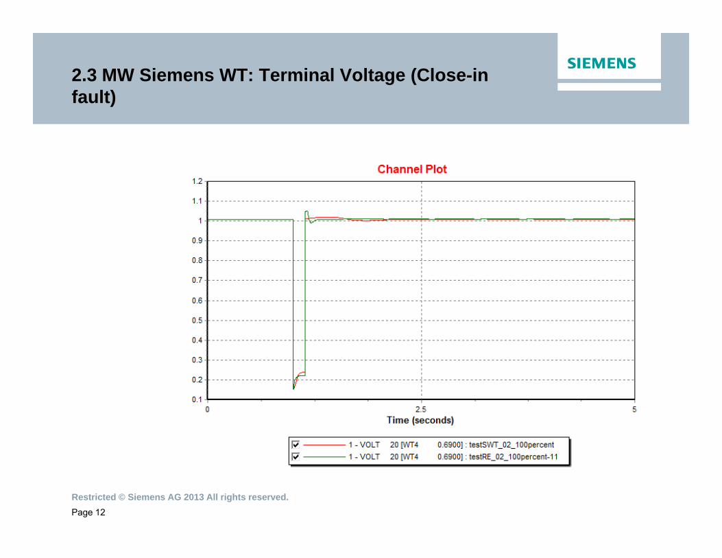
2.3 MW Siemens WT: Terminal Voltage (Close-in fault)
Page 12

Restricted © Siemens AG 2013 All rights reserved.
2.3 MW Siemens WT: Power (Close-in fault)
Page 13

Restricted © Siemens AG 2013 All rights reserved.
2.3 MW Siemens WT: Reactive current (Close-in fault)
Page 14
Restricted © Siemens AG 2013 All rights reserved.
Recent Developments -upgrade of the 2nd Generation RE plant controller
• Generic Renewable Plant Control Model REPCAU1 is designed to interact with the local control of the single equivalent (aggregated) unit with control of active and reactive power (Pref and Qref)
• Active power path is used for frequency control. The reactive power path may be used to control either the POI voltage or reactive power interchange between the plant and the grid or a power factor at the POI.
• Siemens PTI has upgraded the REPCAU1 model to a new REPCMU1 model with the capability to supervise multiple WTGs.
• The new REPCMU1 user written model has the same dynamics of the active and reactive power paths as a standard REPCAU1 model and a provision to supervise local controls of up to 150 WTGs.
Page 15

Restricted © Siemens AG 2013 All rights reserved.
Testing with 4 WTGs supervised by REPCMU1 plant controller
Page 16
POI Voltage (red), Command from the Plant Controller (blue) as a Response toStep Change in Plant Controller Voltage Reference (black)

Restricted © Siemens AG 2013 All rights reserved.
Testing with 4 WTGs supervised by a plant controller
Page 17
WTGs Active Powers as a Response to Step Wise Change in Plant Controller Frequency Reference (black)

Restricted © Siemens AG 2013 All rights reserved.
PV Generic Models
• 1st Generation – standard in version 32• PVGU1, generator converter model• PVEU1, electrical control model• PANELU1, approximation of non-linear PV module output• IRRADU1, user-defined irradiance pattern
• 2nd Generation – standard in version 33.5• REGCAU1, generator converter model for Types 3 & 4• REECAU1, electrical control model for Types 3 & 4• REPCAU1, plant control model for Types 3 & 4
• Composite Load Model – Include basic PV component along with motor, lighting, and other load characteristics – standard in version 32
Page 18

Restricted © Siemens AG 2013 All rights reserved.
Issues in Modeling of Wind & PV type devicesFictitious Frequency Spikes
• Frequency Spike during and after the fault
• Problem is very acute in weak systems.
• Causes False Frequency Relay Trips.
• Temporary Solution:• Disabling Frequency Relay during
fault.
• Long-term Solution:• better frequency calculation –
PTI is investigating this.
Page 19

Restricted © Siemens AG 2013 All rights reserved.
Issues in Modeling of Wind & PV type devices Network Non Convergence
• Problem: Network does not converge at the onset of the fault and after fault clearing
• Possible Cause: During the fault,• unlike synchronous machines, no inertia to fix Ө, and hence
possibly no voltage angle reference, • WTG control model tries to control P,Q; it needs voltage angle
reference to compute the complex current for the given Ө.• PSS®E uses current injection, in the example, voltage is
determined by current: YV = I
Page 20

Restricted © Siemens AG 2013 All rights reserved.
Issues in Modeling of Wind & PV type devicesOther Issues
• Wind and PV models typically are not as accurate for weak interconnections. Manufacturer should document short circuit ratio threshold the model has been validated for
• Mismatch between load flow model and dynamic model limit causes initialization errors
Page 21

Restricted © Siemens AG 2013 All rights reserved.
Summary
• 2nd Generation wind models are available in PSS®E starting version 33.4.
• 2nd Generation PV models are available in PSS®E starting version 33.5.
• Models can be parametrically adjusted to represent any specific wind turbines available in the market.
• More information:• Model description - WECC REMTF documentation, UVIG website• Generic model implementation and “generic parameters” - PSS®E PAG• Generic model data sheets - PSS®E Model Library• User-written model documentation - PSS®E support website
Page 22

Restricted © Siemens AG 2013 All rights reserved.
Thank you for listening!
Ross Altman, Jay Senthil, & Yuriy Kazachkov
Siemens PTI
400 State StreetSchenectady, NY 12305
(518) 395-5066
E-mail: