siemens safety . · pdf filesiemens safety systems applications are based on long experience...
TRANSCRIPT

S o l u t i o n s f o r O i l & G a sS o l u t i o n s f o r O i l & G a s 100.1
A.O.Sveen, NTNU 2007
Siemens Safety Systems.NTNU 19.03.2007, Arnt Olav Sveen
Løsninger» Arbeidsmetoder
Applikasjoner
» Kontroller / Basis System
» Communications
» Human - Machine Interface
» Inngangs og utgangs moduler
» Programvare /programmering
Historikk

S o l u t i o n s f o r O i l & G a sS o l u t i o n s f o r O i l & G a s 100.2
A.O.Sveen, NTNU 2007
Siemens Safety Systems.
The prevention of accidents should not be considered a question of legislation, but instead our responsibility to fellow beings and economic sense
(Werner von Siemens in 1880)

S o l u t i o n s f o r O i l & G a sS o l u t i o n s f o r O i l & G a s 100.3
A.O.Sveen, NTNU 2007
Siemens Safety Systems.
First project 1985, Oseberg Feltsenter
To day nearly 30% of installed safety systems in Norwegian part of the North Sea.
First solutions, Simatic PLC's with additional hardware, 2 PLC'srunning independently.
Late in the eighties the first TÜV approved F systems.
To-day a full range of S7 F, TÜV verified systems, Work procedures according to IEC61508, SINTEF verified

S o l u t i o n s f o r O i l & G a sS o l u t i o n s f o r O i l & G a s 100.4
A.O.Sveen, NTNU 2007
• Stena Don 2000• Statfjord A 2000• Snorre B 2000• Huldra 2000• Oseberg South 2000• Embla 2000• Oseberg Gas 1999• Troll C 1999• Statfjord B 1998• Visund 1998• Eldfisk WIP 1999• Oseberg East 1997
• Petrojarl Foinhaven 1996• Njord A & B 1995• Statfjord C 1995• Vigdis 1995• Ekofisk 1995 • Eldfisk alpha 1993• Brage 1992• Embla 1991• Snorre TLP 1990 • Oseberg A 1988• Oseberg B 1987
Siemens Safety Systems applications are based on long experience
Siemens Safety Systems.

S o l u t i o n s f o r O i l & G a sS o l u t i o n s f o r O i l & G a s 100.5
A.O.Sveen, NTNU 2007
Siemens Safety Systems.S7 400F(H) References (running or under construction)
HULDRA (Norway) 2000
MAERSK XL1 (worlds largest jack up, built in Korea) 2002
EKOFISK 2/7A (installation partly on hold) 2002
HALFDAN HBA (built in Holland) 2002
MAERSK XL2 (built in Korea) 2002
Halfdan 5 platforms (Denmark/built in Singapore and Holland) 2003-2006
Al Shaheen (11 platforms in Qatar) 2003
White Rose FPSO (Canada/ built in Canada/Korea/Abu Dhabi/USA) 2005
P50, Albacore Leste FPSO (Brazil) 2005
PRA1 (Brazil) 2005
Santa Fe (USA, 2 drilling Rigs) 2004
Oseberg Field-centre (Norway) (113 off S7 400/400FH , 35000 I/O) 2005 -2007
Statfjord A/B/C ESD and F&G 2004-2006
SSP300-1/2/3 (China/Brazil/UK/Norway) 2005-2007
Blackford Dolphin 2006
Snorre TLP 2006

S o l u t i o n s f o r O i l & G a sS o l u t i o n s f o r O i l & G a s 100.6
A.O.Sveen, NTNU 2007
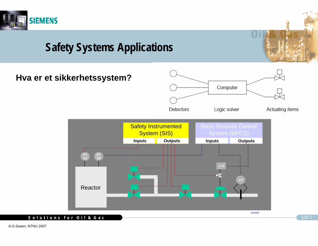
Safety Systems Applications
Hva er et sikkerhetssystem
(SIS)?
Plantpersonnelintervenes
Safety system(automatic)
Basicautomation
Overpressure valve, rupturedisc
Collectionbasin
Active protection
Passive protection
Disaster protectionDisasterprotection
Safety InstrumentedSystem (SIS)
Processvalue
Process alarm
Normal activity
Process controlsystem
Safetyshutdown
S o l u t i o n s f o r O i l & G a sS o l u t i o n s f o r O i l & G a s 100.7
A.O.Sveen, NTNU 2007
Safety Systems Applications
Hva er et sikkerhetssystem?
Low level
I / P
Reactor
PT1A
PT1B
FT
Basic Process Control System (BPCS)
Inputs Outputs
Safety Instrumented System (SIS)
Inputs Outputs
S o l u t i o n s f o r O i l & G a sS o l u t i o n s f o r O i l & G a s 100.8
A.O.Sveen, NTNU 2007
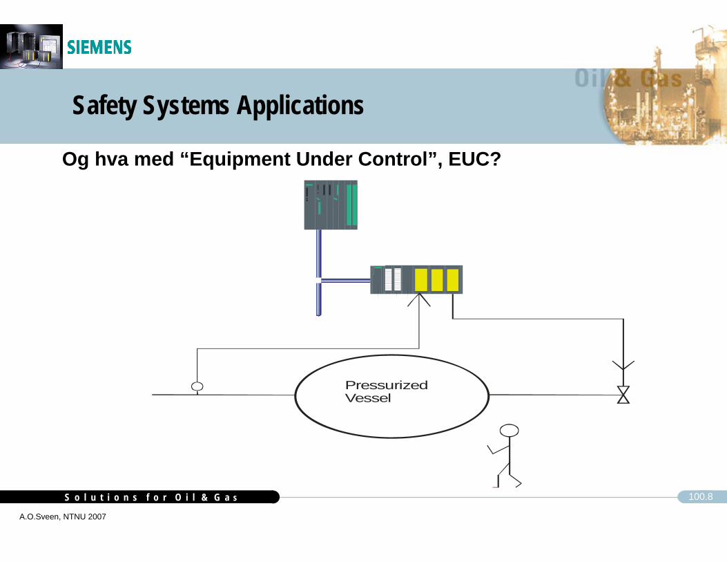
Safety Systems Applications
Og hva med “Equipment Under Control”, EUC?
PressurizedVessel
AS 414 FAS 417 F
ET 200M
IM 153 SafetyModule
F-I/O Modules
PROF
IBUS
-DP
StandardI/O Modules

S o l u t i o n s f o r O i l & G a sS o l u t i o n s f o r O i l & G a s 100.9
A.O.Sveen, NTNU 2007
Safety Systems ApplicationsPurpose
Risk reduction by safety systems, SIS
EUCrisk
EUCrisk
TolerableRisk
TolerableRisk
ResidualRisk
ResidualRisk
Necessary Risk Reduction
Actual Risk Reduction
Risk reduction achieved by all safety-systemsRisk reduction achieved by all safety-systems
From IEC 61508:
Increasing Risk

S o l u t i o n s f o r O i l & G a sS o l u t i o n s f o r O i l & G a s 100.10
A.O.Sveen, NTNU 2007
Safety Systems ApplicationsWhat is Risk?Who decides what is acceptable risk?
Examples of fatality risk figuresRoad accident 100cpm 1.0x10⁻⁴/yr 1 av 100 (levetid 100 år)
Car accident 150cpm 1.5x10⁻⁴/yr 1,5 av 100Accident at work 10cpm 1.0x10⁻⁵/yr 1 av 1000Falling Aircraft 0.02 cpm 2.0x10⁻⁸/yr 2 av 1000 000Lightning strike 0.1cpm 1.0x10⁻⁷/yr 1 av 100 000Insect/Snake bite 0.1cpm 1.0x10⁻⁷/yr 1 av 100 000Smoking 20 per day 5000 cpm 5.0x10⁻³/yr 1 av 2
cpm = chances per million of the population

S o l u t i o n s f o r O i l & G a sS o l u t i o n s f o r O i l & G a s 100.11
A.O.Sveen, NTNU 2007
Safety Systems ApplicationsLi
kelih
ood
Consequence
Tolerable Risk Region
Unacceptable Risk RegionHazard #1
Containment Dike
Control System
Operator Intervention
Safety Instrumented Function
SIL1
SIL2
SIL3
Risk reduction by safety systems, SIS

S o l u t i o n s f o r O i l & G a sS o l u t i o n s f o r O i l & G a s 100.12
A.O.Sveen, NTNU 2007
Safety Systems Applications (cont.)
Safe state?
Can the Safety System bring the area or equipment to a safe state?
How?
What is required? Power Plant

S o l u t i o n s f o r O i l & G a sS o l u t i o n s f o r O i l & G a s 100.13
A.O.Sveen, NTNU 2007
Safety Systems Applications
Applications CoveredESD, Emergency Shutdown
F&G, Fire & Gas Detection, Fire-fighting
Process Shutdown
Fire-pump Logic
Ballast Control
Blow-down
Riser release / Anchor Release
Fire Dampers, Active Smoke Control
HIPPS, High Integrity Pressure Protection System

S o l u t i o n s f o r O i l & G a sS o l u t i o n s f o r O i l & G a s 100.14
A.O.Sveen, NTNU 2007
A utros afe
E ng ine ering S ta tio n
C O L O R H A RD C O P Y
E S D C rit.A c t io n P .
A LA R MP R IN T ER
C E N T R A L C O N T R O L R O O M (C C R )
C E R
P R O C E S S L IR
O p e ra to r S ta t io n 1 O p e ra to r S tat io n 2 O p e ra to r S tat io n 3 O p e ra to r S tat io n 4 IM S C lien ts
ToE SD M a trix
F& GM A T R IX
O p e ra to r s t. 6P ro c. S im .
L Q L E R
C 1 L E R C 2 L E R C 3 L E R C 4 L E R
IM SIP 21+
T O L Q LE RT O P R O C E S S L IRT O C 1 L E RT O C 2 L E RT O C 3 L E RT O C 4 L E R
T O C E R
I/O modules+ serial comm.
R em ote
T o S ta to il n et .
M e te r ing
C IS C O
C IS C O
C IS C O
C IS C O
Indu s tria l P ro jec tsan d Te chnica l S erv ice s
S I E M E N S
O p e r. s t. 8
L A R G ES C R E E N
O p e r. s t. 7
P ro fibu s D P
I/O modules+ serial comm.
R em ote
Pro fibus D PT O C E R
U 0 1R e m o te I/O
R e m o te I /OC 0 1
R e m o te I /O C 1 0
R e m o te I /O C 0 2/0 3
O p e ra to r S tat io n 5
C S 7 -S e rve r C ab in ets w ith c o o lin g fac il it ie s
S IL 1 /3
S im a tic S 7 H -S y nc h . line s(F ib re )
A utro safe 3 20
I/O modules+ serial comm.
F T C x1S IL 2
Red. I/O F-modules
FT C x5S IL3
SIE
ME
NS
SIE
ME
NS
E 01E S D
S 7-40 0F H
T O C E R O S M
I/O m odulespartly F Modules
R em ote
I0 1IN T E R F A C E S
SIE
ME
NS
SIE
ME
NS
I/O modules+ serial comm.
S P C U x 2
MODEM.
SIE
ME
NS
SIEM
EN
S
I/O modules+ serial comm.
F T C x1
Red. I/O modulespartly F Modules
FT C x5
F & GR IO S IL2
T O C E R
P rofib u s D P /P rof isa fe
T O C E RT O C E R
TO C E RO S M
A utros a fe
S IL2
F & G F 03S 7 -40 0F /H
SIE
ME
NS
SIE
ME
NS
P ro fiS a fe toF& G M atrix
Red. I/O F-modules
FT C x 5S IL 3
SIE
ME
NS
SIE
ME
NS
F 0 1F & G
S 7-40 0F H
P ro fiS a feS IL 3
Red. I/O F-modules
FT C x 5S IL3
SIE
ME
NS
SIE
ME
NS
F0 2F& G
S 7-4 0 0 FH
P ro fiS a fe to 4 o ff A u tro sa fein L E R C 01 -C 04
Red. I/O F-modules
FT C x1S IL1 /3
SIE
ME
NS
SIE
ME
NS
P 01P S D
S 7-40 0 FH
SIE
ME
NS
G 01 /L0 1P C SG en 1 /P D C SS 7-40 0
I/O modules+ serial comm.
F T C x1
SIE
ME
NS
G 02 /L0 2P C SG en 2 /P D C SS 7 -40 0
I/O modules+ serial comm.
F T C x1
SIE
ME
NS
U 01P C SU tili tie s
S 7 -4 0 0
I/O modules+ serial comm.
F T C x1
SIE
ME
NS
C 01 /C 1 0P C SM a in P / S u ppo rtS 7 -40 0
H 02P C SM a rin eC P U AS 7-40 0 FH
SIE
ME
NS
I/O modules+ serial comm.
R em ote
H 02P C SM a rineC P U BS 7-40 0F H
P 02P S DS ub se aS 7 -4 0 0 FH
B 0 1P C SB a llas t C P U AS 7-40 0F H
I/O modules+ serial comm.
F T C x1
SIE
ME
NS
P ro fiS a feS IL3 toF 02
T O C E R O S M
I/O modulespartly F Modules
R e m ote
A utros afe
S IL 2
B 01P C SB a llas t C P U BS 7-4 0 0 FH
I/O modules+ serial comm.
F T C x1
SIE
ME
NS
P ro fiS afeS IL3 toF 02
T O C E R O S M
I/O modulespartly F Modules
R em ote
A utros afe
S IL2
B 02P C SB a llas t C P U AS 7-40 0F H
I/O modules+ serial comm.
F T C x1
SIE
ME
NS
P ro fiS a feS IL3 toF 02
TO C E R O S M
I/O modulespartly F Modules
R e m ote
A utros afe
S IL 2
B 02P C SB a llas t C P U BS 7-40 0F H
I/O modules+ serial comm.
F T C x1
SIE
ME
NS
P ro fiS afeS IL3 toF 02
L Q L E R
T O C E R O S M
I/O modulespartly F Modules
R em ote
A utros afe
S IL2
F 0 3F & G
S 7 -40 0F
I/O modules+ serial comm.
F T C x1
SIE
ME
NS
P ro fiS a feS IL3 toF 02
S im a tic S 7 H-S y nc h . lin es(F ib re )
S im a tic S 7 H-S ynch . lin es(F ib re )
P R O F IB U S /P ro fiS a fe ( S IL 3 ) (F ib re )
Siemens Safety Systems,Topology for total platform control system including safety

S o l u t i o n s f o r O i l & G a sS o l u t i o n s f o r O i l & G a s 100.15
A.O.Sveen, NTNU 2007
SIEM
ENS
S7-400FH (SIL3, and redundant)
PROFIBUS/ProfiSafe (SIL3) Industrial Ethernet 100 Mbit
F&G ESD Wide ScreenOverview
Ethernet 100 Mbit
Software is implemented according to procedure, SIL 3
SIEM
ENS
Industrial Ethernet 100 Mbit
Ethernet 100 Mbit
Communication to other nodes SIL3
Commands from OS to SIL3
PROFIBUS/ProfiSafe (SIL3)
PROFIBUS/ProfiSafe (SIL3)
SIL 2
Fire & Gas Topology (sample)
P ow er
F ire Brig. recvd.
F ire vent. activ.
F ire ext.. acktivated
0
A L A R M
?
C
987
654321
Silence buzzer
Silence sounders
Reset
M ore Alarms
P rewarnin g
E arly w arning
S ystem fault
F unction disabled
T est
F ault
S elf V erify
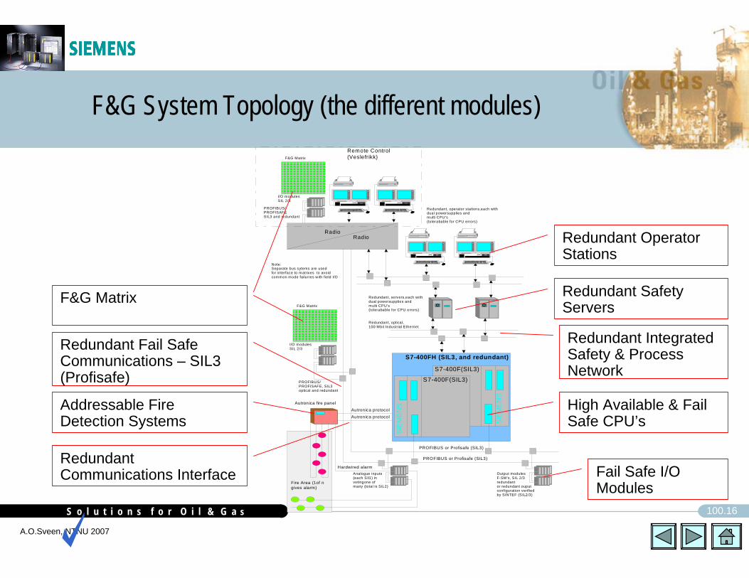
S o l u t i o n s f o r O i l & G a sS o l u t i o n s f o r O i l & G a s 100.16
A.O.Sveen, NTNU 2007
F&G System Topology (the different modules)
PROFIBUS or Profisafe (SIL3)
RadioRadio
SIEM
ENS
SIEM
ENS
S7-400F(SIL3)
S7-400F(SIL3)
S7-400FH (SIL3, and redundant)
PROFIBUS or Profisafe (SIL3)
I/O modulesSIL 2/3
F&G Matrix
PROFIBUS/PROFISAFESIL3 and redundant
Redundant, optical,100 Mbit Industrial Ethernet
Remote Control(Veslefrikk)
Redundant, servers,each withdual powersupplies andmulti CPU's(tolerabable for CPU errors)
Redundant, operator stations,each withdual powersupplies andmulti CPU's(tolerabable for CPU errors)
Output modulesF-SM's, SIL 2/3redundantor redundant ouput configuration verified by SINTEF (SIL2/3)
Analogue inputs(each SIl1) invotingone of many (total is SIL2)
I/O modulesSIL 2/3
F&G Matrix
PROFIBUS/PROFISAFE, SIL3optical and redundant
Note:Separate bus sytems are used for interface to matrixes to avoid common mode failurres with field I/O
Autronica protocolAutronica protocol
Hardwired alarm
Autron ica fire panel
Fire Area (1of n gives alarm)
Fail Safe I/O Modules
High Available & Fail Safe CPU’s
Redundant Integrated Safety & Process Network
Addressable Fire Detection Systems
Redundant Communications Interface
Redundant Fail Safe Communications – SIL3 (Profisafe)
Redundant Safety Servers
Redundant Operator Stations
F&G Matrix

S o l u t i o n s f o r O i l & G a sS o l u t i o n s f o r O i l & G a s 100.17
A.O.Sveen, NTNU 2007
ESD Topology (sample)SI
EMEN
S
S7-400F(SIL3)
S7-400FH (SIL3, and redundant)
PROFIBUS/ProfiSafe (SIL3)
ESD Matrix.
Controller Cabinet
Operator Stations
Industrial Ethernet 100 Mbit
F&G ESD Wide ScreenOverview
Ethernet 100 Mbit
Redundant Safety Servers
(built in redundancy and auto-repair)
Software is implemented according to procedure, SIL 3
EngineeringStation
S7-400F(SIL3)
SIEM
ENS
Industrial Ethernet 100 Mbit
Ethernet 100 Mbit
Communication to other nodes SIL3
Commands from OS to SIL3
RemoteInput / Output modules, F-SM SIL2/3or ET200M SIL0/1
Hardware design according to procedure, SIL 3
Remote "fail safe"Input /output modulesF-SM's, SIL 2/3
Field Termination Cabinet
PROFIBUS/ProfiSafe (SIL3)
PROFIBUS/ProfiSafe (SIL3)
RemoteInput / Output modules, IS1or ET200M SIL0/1

S o l u t i o n s f o r O i l & G a sS o l u t i o n s f o r O i l & G a s 100.18
A.O.Sveen, NTNU 2007
PSD Topology (sample)SI
EMEN
S
S7-400F(SIL3)
Controller Cabinet
Operator Stations
Industrial Ethernet 100 Mbit
Redundant Servers
Software is implemented according to procedure, SIL 3
EngineeringStation
S7-400F(SIL3)
SIEM
ENS
Industrial Ethernet 100 Mbit
Ethernet 100 Mbit
Communication to other nodes SIL3
Commands from OS to SIL3
Hardware design according to procedure, SIL 3
Remote ET200iSor"fail safe"Input /output modulesF-SM's, SIL 2/3
Field Termination Cabinetor Junction Box
PROFIBUS/ProfiSafe (SIL3)
RemoteInput / Output modules, IS1or ET200M SIL0/1
Ethernet 100 Mbit

S o l u t i o n s f o r O i l & G a sS o l u t i o n s f o r O i l & G a s 100.19
A.O.Sveen, NTNU 2007
Marine Control System (SIL 3)
SIEM
ENS
S7-400F(SIL3)
ACPU
S7-400FH (SIL3, and redundant) Controller Cabinet B
Operator Stations
Industrial Ethernet 100 Mbit
Redundant Servers
Software is implemented according to procedure, SIL 3
EngineeringStation
S7-400F(SIL3)
B CPU
SIEM
ENS
Industrial Ethernet 100 Mbit
Ethernet 100 Mbit
Communication to other nodes SIL3
Commands from OS to SIL3
Hardware design according to procedure, SIL 3
Remote "fail safe"Input /output modulesF-SM's, SIL 2/3
Field Termination Cabinetor Junction Box
PROFIBUS/ProfiSafe (SIL3)
RemoteInput / Output modules, IS1or ET200M SIL0/1
Controller Cabinet A
Synchronization link
Manual Ballast Functions

S o l u t i o n s f o r O i l & G a sS o l u t i o n s f o r O i l & G a s 100.20
A.O.Sveen, NTNU 2007
Subsea PSD solution and HIPPS, both SIL3
Supplier Document ReviewAccepted
SCSSV
PMV
PWV
HIPPS 1 HIPPS 2
Choke
Titanium Pipe/enclosure
Titanium Pipe/enclosure
SSIV
ESD, S7-400F, SIL3
Remote F-SM, SIL3
PRO
FISA
FE ,S
IL3
Topside
Subsea
(Remote I/O)
PSD, S7-400F, SIL2/3 PCS, S7-400
RIO (F.SM.)
Hydraulic Supply
Bleed Hydraulic (SIL 3)
PSD Remote I/O Simatic S7F-SM (SIL3)
Twisted Pair Fiber Optic Cable Umbilical with center line
1
23
X x=Number of connection`s
5
Profibus DP/ProfiSafe (SIL3)
Hydraulic 6 Riser (Stigerør)
EV
PSV
HPU
Production
T
PRO
FBU
S
PRO
FISA
FE ,S
IL3
Remote F-SM, SIL3
4-2 0 m A
P T P T
4-2 0 m A
Slot no. 1
Slot no. 2-4
P T
T
P T
TP T
P TP T
P T
P T
S5 95F/S7 300F
Subsea HIPPS/SIL 3
P T
P T
RF-M odem
Profibus DP(to topside modem)19.2 Kbits
RF- Modem
T
4-2 0 m A
P T
RF-M odem
RF-Modem 183 Kbits

S o l u t i o n s f o r O i l & G a sS o l u t i o n s f o r O i l & G a s 100.21
A.O.Sveen, NTNU 2007
IEC 61508
The safety level is applicable for:The total solution All the projects lifecycles
The system solution covers EUC, including HMIHW engineering, construction and testing
By use of standard hardware set-upWith special modules approved by TÜV
SoftwareFunction blocks (basic blocks approved by TÜV)Protocols and drivers approved by TÜVApplication program (according to procedure)
Maintenance proceduresOperation and Modification Procedures
S o l u t i o n s f o r O i l & G a sS o l u t i o n s f o r O i l & G a s 100.22
A.O.Sveen, NTNU 2007
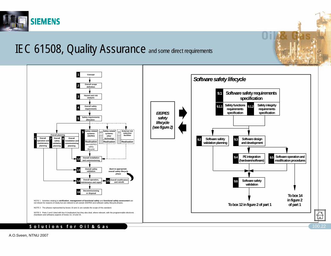
IEC 61508, Quality Assurance and some direct requirements
Software safety validation
9.6
Safety functions requirements specification
Safety integrity requirements specification
9.1
9.1.1 9.1.2
Software safety requirements specification
To box 12 in figure 2 of part 1
Software safety validation planning
Software design and development
9.39.2
9.4 Software operation and modification procedures
9.5PE integration (hardware/software)
To box 14 in figure 2 of part 1
E/E/PES safety
lifecycle(see figure 2)
Software safety lifecycle
10 11
NOTE 1 Activities relating to verification, management of functional safety and functional safety assessment are not shown for reasons of clarity but are relevent to all overall, E/E/PES and software safety lifecycle phases.
NOTE 2 The phases represented by boxes 10 and 11 are outside the scope of this standard.
NOTE 3 Parts 2 and 3 deal with box 9 (realisation) but they also deal, where relevant, with the programmable electronic (hardware and software) aspects of boxes 13, 14 and 15.
Concept1
Overall scopedefinition2
Hazard and risk analysis3
Overall safety requirements4
Safety requirements allocation 5
Back to appropriate overall safety lifecycle
phase
Overall safety validation13
Overall operation,maintenance and repair
Overall modification and retrofit14 15
Decommissioningor disposal16
Safety-relatedsystems:E/E/PES
Realisation(see E/E/PES
safetylifecycle)
9 Safety-relatedsystems:
other technology
Realisation
Overall installationand commissioning12
8
Overall planningOveralI
operation andmaintenance
planning
OveralI installation andcommissioning
planning
Overallsafety
validationplanning
6 7 8
External risk reduction facilities
Realisation

S o l u t i o n s f o r O i l & G a sS o l u t i o n s f o r O i l & G a s 100.23
A.O.Sveen, NTNU 2007
IEC 61508, Implementation according to proven procedures.
Safety requirements shall be specified, and the requirements shall be traceable through all engineering phases.
Internal procedures for development of software according to IEC61508
Procedures developed in co-operation with SINTEF Tele and Data.– specification– planning– implementation– verification– validation– modifications.
Internal procedures for hardware design and production according to IEC61508
Made on the same structure as the SINTEF verified SW procedure.
S o l u t i o n s f o r O i l & G a sS o l u t i o n s f o r O i l & G a s 100.24
A.O.Sveen, NTNU 2007
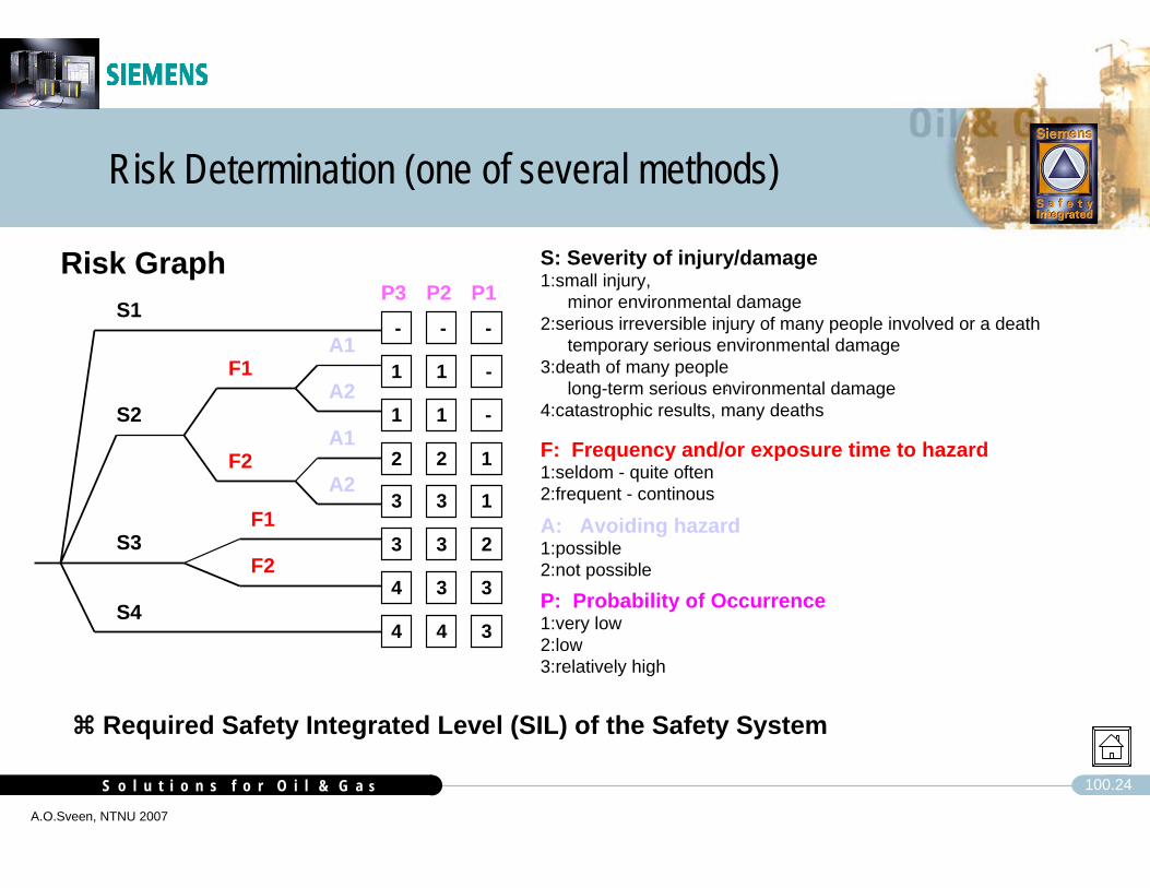
Risk Graph
Risk Determination (one of several methods)
:
S1
F1
F2
F1
F2
A1
A2
A1
A2
S2
S3
S4
P3-
1
1
2
3
3
4
4
-
1
1
2
3
3
3
4
-
-
-
1
1
2
3
3
P2 P1S: Severity of injury/damage1:small injury,
minor environmental damage2:serious irreversible injury of many people involved or a death
temporary serious environmental damage3:death of many people
long-term serious environmental damage4:catastrophic results, many deaths
F: Frequency and/or exposure time to hazard1:seldom - quite often2:frequent - continous
A: Avoiding hazard1:possible2:not possible
P: Probability of Occurrence1:very low2:low3:relatively high
Required Safety Integrated Level (SIL) of the Safety System

S o l u t i o n s f o r O i l & G a sS o l u t i o n s f o r O i l & G a s 100.25
A.O.Sveen, NTNU 2007
S7-400F/FHS5-95F
Safety Integrity Levels, direct requirement IEC61508
Independent Authority (e.g. TÜV) classifies control systems according to their safety measures
Requirement Class (AK)
DIN V 19250
Safety Integrity Level (SIL)
IEC 61508
Probability of failure on demand per h
(constant operation) (IEC 61508)
Probability of failure on demand (on
demand operation) (IEC 61508)
Control CategoryEN 954-1
AK 1 --- -- -- B
AK 2 and 3 SIL 1 10-5 to 10-6 10-1 to 10-2 1 and 2
AK 4 SIL 2 10-6 to 10-5 10-2 to 10-3 3
AK 5 and 6 SIL 3 10-7 to 10-8 10-3 to 10-4 4
AK 7 and 8 SIL 4 10-8 to 10-9 10-4 to 10-x ---

S o l u t i o n s f o r O i l & G a sS o l u t i o n s f o r O i l & G a s 100.26
A.O.Sveen, NTNU 2007
Safety Integrity Levels, direct requirement IEC61508IEC61508 requires higher fail safe fraction from “intelligent” components
Safe failure fraction Hardware fault tolerance
0 1 2
< 60 % SIL1 SIL2 SIL3
60 % - 90 % SIL2 SIL3 SIL4
90 % - 99 % SIL3 SIL4 SIL4
> 99 % SIL3 SIL4 SIL4
Hardware safety integrity: architectural constraintson type B safety-related subsystems
Safe failure fraction Hardware fault tolerance
0 1 2
< 60 % not allowed SIL1 SIL2
60 % - 90 % SIL1 SIL2 SIL3
90 % - 99 % SIL2 SIL3 SIL4
> 99 % SIL3 SIL4 SIL4
Hardware safety integrity: architectural constraints on type A safety-related subsystems

S o l u t i o n s f o r O i l & G a sS o l u t i o n s f o r O i l & G a s 100.27
A.O.Sveen, NTNU 2007
Safety Integrity Levels, PFD calculation
AIPROFISAFE
CPU DOPROFISAFE
ESV
4-20 mA
Gas detector
Control valve
F&G loop with Gas detector and control valve.
Safety reliability Block diagram:

S o l u t i o n s f o r O i l & G a sS o l u t i o n s f o r O i l & G a s 100.28
A.O.Sveen, NTNU 2007
Safety Control System, SIMATIC S7 - 400F/FH
Controller S7 400F /FH
S7-414-4H1.4MB64MB
S7-417-4H20MB64MB
S7-416F-22.8MB64MB
S7-317F-2DP1.4MB64MB
S7-315F-2DP182kB8MB
IM 151-7F64kB8MB

S o l u t i o n s f o r O i l & G a sS o l u t i o n s f o r O i l & G a s 100.29
A.O.Sveen, NTNU 2007
Components S7-400F/FH
High available System S7-417FH as a basisCPU 417-4HTÜV certified failsafe function blocks
Engineering /Hardware Configuration/ProgrammingConfiguration of the S7-400F-Hardware with Standard HW-Config.Graphical Engineering (programming) with Standard CFC (Continuous Function Chart)TÜV certified failsafe function blocks in a separate library(failsafe function blocks to be used in the fail safe part) Coexistence of Standard- and F-Applications in one CPU
Connection to the ProcessFailsafe I/O modulesSpecial Profil PROFIsafe to ensure failsafe communication via Standard-Profibus-DP

S o l u t i o n s f o r O i l & G a sS o l u t i o n s f o r O i l & G a s 100.30
A.O.Sveen, NTNU 2007
Basic principle “Protected F-Islands”
Safety-relateduser program
CPUoperating system
Standard user programs
CPUhardware
Safety-related frame
Any faults inother modules, environmental
factors
FailsafeI/O
modules

S o l u t i o n s f o r O i l & G a sS o l u t i o n s f o r O i l & G a s 100.31
A.O.Sveen, NTNU 2007
S7 400F F/H system - modularity,
PCStandard Engineering Software
Standard-ProfibusDP
F-Application Program
F-Programming Tool
F-I/O’s (ET200M)
ProfiSafe Protocol
RU
N-P
RU
NSTO
PC
MR
ES
RU
N-P
RU
NSTO
PC
MR
ES
Standard-CPU 417-4H
Standard I/O’s (ET200M)

S o l u t i o n s f o r O i l & G a sS o l u t i o n s f o r O i l & G a s 100.32
A.O.Sveen, NTNU 2007
S7-400HRedundancy Principle
CCCPPPUUU
DDDEEE
DDDAAA
AAAEEE
AAAAAA
PPPSSS
CCCPPP
CCCPPPUUU
DDDEEE
DDDAAA
AAAEEE
AAAAAA
CCCPPP
PPPSSS
PROCESSPROCESS
Synchronization,information
and status exchange
IIMM
DDEE
AAEE
AAAA
DDAA
IIMM
FFMM
S o l u t i o n s f o r O i l & G a sS o l u t i o n s f o r O i l & G a s 100.33
A.O.Sveen, NTNU 2007
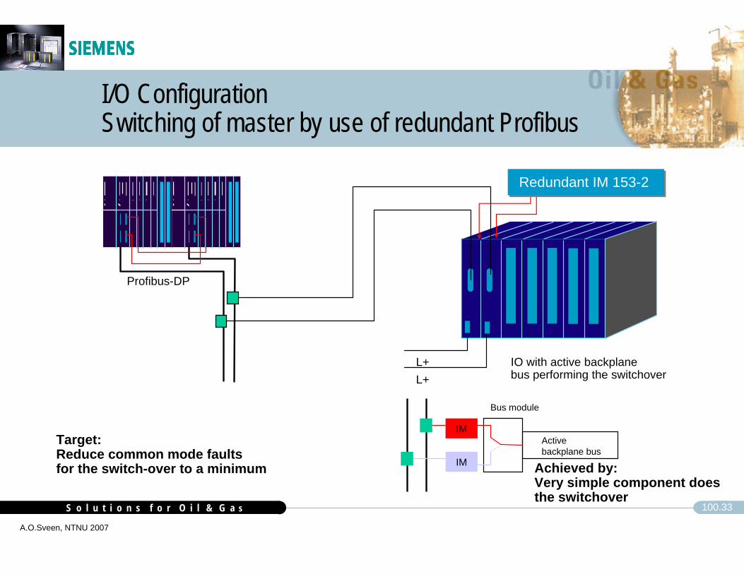
I/O ConfigurationSwitching of master by use of redundant Profibus
Profibus-DP
IM
IM
Bus module
Active backplane bus
IO with active backplane bus performing the switchover
L+L+
Redundant IM 153-2 Redundant IM 153-2
Target:Reduce common mode faultsfor the switch-over to a minimum Achieved by:
Very simple component doesthe switchover
S o l u t i o n s f o r O i l & G a sS o l u t i o n s f o r O i l & G a s 100.34
A.O.Sveen, NTNU 2007
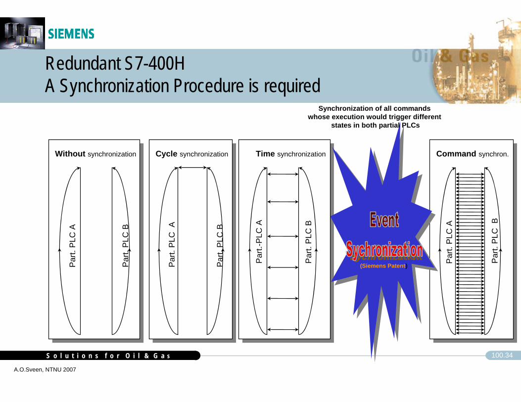
Redundant S7-400HA Synchronization Procedure is required
Par
t. P
LC A
Par
t. P
LC B
Cycle synchronization
Par
t.-P
LC A
Par
t. P
LC B
Time synchronization Command synchron.
Par
t. P
LC A
Par
t. P
LC B
Par
t. P
LC A
Par
t. P
LC B
Without synchronization
(Siemens Patent)
Synchronization of all commands whose execution would trigger different
states in both partial PLCs

S o l u t i o n s f o r O i l & G a sS o l u t i o n s f o r O i l & G a s 100.35
A.O.Sveen, NTNU 2007
Flexible Set-up‘sTogether, the listed principles result in a flexible set-up
redundant S7-400FHredundant PROFIBUS-DPF-E/A ModulsSIL3, AK6
redundant S7-400FHredundant PROFIBUS-DPredundant F-E/A ModulsSIL3, AK6
S7-400FPROFIBUS-DPF-E/A ModulsSIL 3, AK6
Fail Safe Fail Safe and High Availability
AS 414 FAS 417 F
ET 200M
IM 153
SafetyModule
F-I/O Modules
PRO
FIB
US
-DP
StandardI/O Modules
PRO
FIB
US
-DP
ET 200M
2 xIM 153-2
SafetyModule
F-I/O Modules
AS 414 FAS 417 F
StandardI/O Modules
PRO
FIB
US
-DP
ET 200M
F-I/O Modulesredundant
AS 414 FAS 417 F

S o l u t i o n s f o r O i l & G a sS o l u t i o n s f o r O i l & G a s 100.36
A.O.Sveen, NTNU 2007
Flexible Set-up‘s
Mix to meet the goals of the applicationField Device redundancy can be designed to achieve safety and availability goalsCPU/IO safety is not dependant on redundancy
All components are SIL3-capableRedundancy only for availability
AI DI
DO
DOAI
AI DI
DO
DOAI
AI
2oo3
2oo2D (Dual 1oo1D)
1oo1D
1oo2D
1oo3
3oo3

S o l u t i o n s f o r O i l & G a sS o l u t i o n s f o r O i l & G a s 100.37
A.O.Sveen, NTNU 2007
Flexible Set-up‘s
IO and Field Device redundancy can be matched to:
Minimize costMaximize availability
AI DI
DO
DOAI
AI DI
DO
DOAI
AI
2oo3
2oo3 PT1oo2 Valves
2oo2D
2oo32oo3

S o l u t i o n s f o r O i l & G a sS o l u t i o n s f o r O i l & G a s 100.38
A.O.Sveen, NTNU 2007
Flexible Set-up‘s
Multiple Fault TolerantFieldbus architecture allows system to tolerate multiple faults without interruptionI/O redundancy independent of CPU redundancy
All components rated for SIL3No degraded modeSafety not dependent on redundancyAI D
I
DO
DOAI
AI DI
DO
DOAI
AI
2oo3 PT1oo2 Valves
2oo3
S o l u t i o n s f o r O i l & G a sS o l u t i o n s f o r O i l & G a s 100.39
A.O.Sveen, NTNU 2007
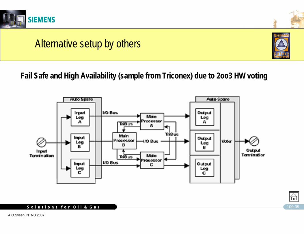
Alternative setup by others
Fail Safe and High Availability (sample from Triconex) due to 2oo3 HW voting

S o l u t i o n s f o r O i l & G a sS o l u t i o n s f o r O i l & G a s 100.40
A.O.Sveen, NTNU 2007
Input and output modules to SIL 3, 2 and 1
RUN-PRUN
STOPCMRES
S7-400FH-CPU
F-SM´s (DI,DO,AI)Standard SM´sRUN-PRUN
STOPCMRES
F-SM, Fail Safe Modules
ET 200 MCan also cover SIL1 and SIL2 solutions
ET200 iSPSmall granularity modules for Zone 1,can also cover SIL1 applications
SIL3, 2 or 1dependant on configuration (TÜV) – SIL 3 also in single configuration for most modules– SIL 3 with single or redundant bus connection
Allows standard modules on same bus

S o l u t i o n s f o r O i l & G a sS o l u t i o n s f o r O i l & G a s 100.41
A.O.Sveen, NTNU 2007
Architecture S7-300 Fail Safe Modules (sample)
Microcontroller
Outputdriver
Dual-portRAM
Bus interface
Seconddisconnection facility
(can be read back)
L+
F-Digital Output, with built in redundancy, self verification and degrading
Microcontroller
Output VSupply
If ”Output driver” fails to bringoutput to safe state, ”0”, the microcontroller does, based onthe read back, order the ”Seconddisconnection facility” to shutthe card down

S o l u t i o n s f o r O i l & G a sS o l u t i o n s f o r O i l & G a s 100.42
A.O.Sveen, NTNU 2007
S7-300 Fail Safe Modules
Redundant microcontroller in each IO moduleSafety Integrated Level
1oo1 evaluation, SIL 2, AK 41oo2 evaluation, SIL 3, AK 6
Diagnose of internal and external errorsmutual function checking of the microcontrollersinput or output testbranching of the input signals to both microcontrollersdiscrepancy analysis of the redundant input signalsreadback of the output signals and discrepancy analysis
Second disconnection facility in the case of outputsCommunication with CPU via Profisafe

S o l u t i o n s f o r O i l & G a sS o l u t i o n s f o r O i l & G a s 100.43
A.O.Sveen, NTNU 2007
S7-300 Fail Safe I/O Modules
A large number of modules are available
SM326F, DI DC24V 24 x SIL2, 12 x SIL3, with diagnostics interrupt
SM326F, DI NAMUR [EEx ib] 8 x SIL2, 4 x SIL3 with diagnostics interrupt
SM326F, DO DC24V/2A 10 x SIL3, current source, diagnostics interrupt
SM336F, AI 4-20mA 6 x SIL2 or 3, with diagnostics interrupt
and more

S o l u t i o n s f o r O i l & G a sS o l u t i o n s f o r O i l & G a s 100.44
A.O.Sveen, NTNU 2007
Fail Safe I/O ModulesLibrary for interfaces to field devices
SAFETY INPUTS AND OUTPUTS, S7 400F WITH SAFETY I/O MODULES, F-SM’S
AI-41F Safe analogue input, 4-20 mA, 2 Wire, SIL 2.AI-43F Safe analogue input, 4-20 mA, 3 Wire, SIL 2, current sourceAI-44F Safe analogue input, 4-20 mA, 3 Wire, SIL 2, high power consumpt.AI-50F Safe high available analogue input, 4-20 mA, 2 Wire, 2 oo 3.AI-51F Safe analogue input, 4-20 mA, 2 wire, to digital, SIL 2AI-IS-41F Safe analogue input, 4-20 mA, EEx(i)(a) , 2 Wire, SIL 2.AI-IS-51F Safe analogue input, EEx ib IIC, 4-20 mA, to digital, SIL 2DI-41F Safe digital input, SIL 2DI-42F Safe high available, digital input, SIL 2DI-44F Safe digital input from clean contact / NAMUR, SIL2DI-IS-41F Safe, EEx ib IIC, digital input from clean contact / NAMUR, SIL2DI-IS-46F Safe, high available, EEx ib IIC, double clean contact/ NAMUR, SIL2 /DI-IS-46F Safe, EEx ib IIC, double clean contact /NAMUR, SIL3.DO-41F Safe, digital output, 24 V DC, 2A, SIL2 / 3DO-41FR Safe digital output, SIL 2 with relay, SIL2DO-RE-45F Safe, high available, digital output, 24 V DC, 2A, SIL2 /3DO-46F Safe, digital output with manual release, 24 V DC, 2A, SIL2 /3DI-MA-41F Safe, high available digital input from pushbutton, SIL 3DI-MA-42F Safe, high available digital input from pushbutton, SIL 2DI-MA-43F Safe, digital input from pushbutton, SIL 3DI-MA-44F Safe, digital input from pushbutton, SIL 2DI-MA-45F Safe, high available digital input from pushbutton, SIL 3DI-MA-46F Safe, high available digital input from pushbutton, SIL 2DI-MA-47F Safe digital input from pushbutton (with LED), open contact, SIL 2DI-MA-48F Safe digital input from pushbutton (without LED), open contact, SIL 2DI-MA-49F Safe digital input from pushbutton, NAMUR, SIL 2DO-MA-41F Safe digital output to LED / LAMP, SIL2/3DO-MA-42F Safe digital output to two LED / LAMP, SIL 2/3DO-MA-43F Safe digital output to LED in fire fighting release pushbutton, SIL 2
POW ER DISTRIBUTION
L + 24 VDC
L- 0V
Hardware Typecircuit code DO-RE-45F
6ES7 326-2BF00-0AB0
1M
1L+
3
4
2A
ch 0
21
22
FIELD TERMINATION CABINETFIELD
TERMINAL RAILFIELD
EQUIPMENT
10 DO, SAFE
Main Switch
Read back
JUNCTIONBOX
OVERRIDE
ESD MATRIX
L- 0V
L+ 24 VDC
DO-MA-41
0 V distrib.
L+
M
6ES7 321-1BL00-0AA0DI 32 ch
16A10A
2L+172L+183L+373L+38
3M392M202M19
3M40
6ES7 326-2BF00-0AB0
1M
1L+
3
4
21
22
10 DO, SAFE
Main Switch
Read back
2L+172L+183L+373L+38
3M392M202M19
3M400 V distrib.
16ALibrary with standard, pre-verified instrument interfaces (made in Norway)

S o l u t i o n s f o r O i l & G a sS o l u t i o n s f o r O i l & G a s 100.45
A.O.Sveen, NTNU 2007
Man må ofte ting i sammenheng før en oppdager at det kan være spesielle feilsituasjoner
Fail Safe I/O ModulesDevelopment of interfaces to field devices

S o l u t i o n s f o r O i l & G a sS o l u t i o n s f o r O i l & G a s 100.46
A.O.Sveen, NTNU 2007
Det er utrolig hvor lite komplisert det skal være før noe kan gå galt
Fail Safe I/O ModulesDevelopment of interfaces to field devices

S o l u t i o n s f o r O i l & G a sS o l u t i o n s f o r O i l & G a s 100.47
A.O.Sveen, NTNU 2007
PROFIBUS PA Fieldbus solution to SIL1 / 2.CPU 417H
CP443-5EDP Master
IM 157Link
CPU 417H
CP443-5EDP Master
IM 157Link
DP
PA slavePT....
IM 157Kobler
DP
PA
EX sone
ProfiSafe PA, TÜV certified SIL 2, is scheduled.
SINTEF Study "Evaluation of PROFIBUS PA against SIL1 / 2 requirements.
Conclusion, SIL 1, provided set-up with extensive diagnosis is selected.
Fail to operate figures are nearly satisfying SIL2 requirements
S o l u t i o n s f o r O i l & G a sS o l u t i o n s f o r O i l & G a s 100.48
A.O.Sveen, NTNU 2007
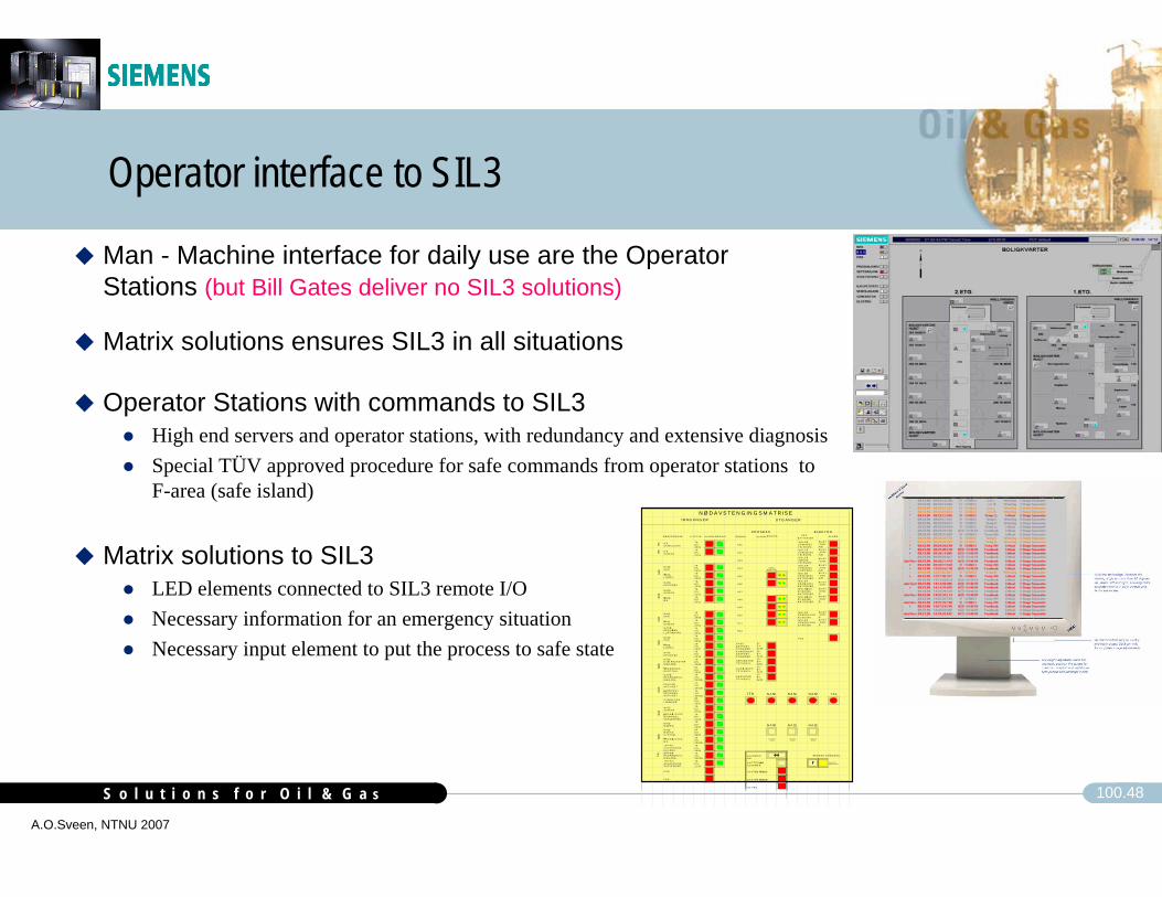
Man - Machine interface for daily use are the Operator Stations (but Bill Gates deliver no SIL3 solutions)
Operator interface to SIL3
N Ø D A V S T E N G IN G S M A T R IS EIN N G A N G E R U T G A N G E R
B E S K R IV E L S E U T S T Y R A L A R MB A T T E R I E R
A L A R MU P SB R Ø N N A L A R M
A 0 1
A 1 2
A 1 1
A 1 0
A 0 9
A 0 8
A 0 7
A 0 5
A 0 6
A 0 2
A 0 3
A 0 47 9 -E S -2 0 0 17 9 -E S -2 0 027 9 -E S -2 0 037 9 -E S -2 1 017 9 -E S -2 2 01
7 9 -E S -2 0 047 9 -E S -2 1 02
7 9 -E S -2 0 057 9 -E S -2 1 03
7 9 -E Y -2 1 09
7 9 -E S -2 0 067 9 -E S -2 0 07
7 9 -E S -2 0 08
7 9 -E S -2 1 04
7 9 -E S -2 2 02
7 9 -E S -2 0 16
8 6 -E S -2 2 03
8 2 -E S -2 0 01
7 9 -E S -2 0 09
7 9 -E S -2 1 05
7 0 -X S -2 0 02 B
7 0 -X S -2 0 03 B
7 0 -X S -2 0 04 B
7 1 -X S -2 0 51 B7 5 -X S -2 0 5 1 B8 6 -E S -2 0 01
N A S 0S K R
N A S 0L IV B Å T
N A S 0H E L ID E K K
N A S 0S K R V F R
N A S 0M G
IT KS K R H U L D R A
IT KS K R V F R
N A S 1S K R
N A S 1S K R V F R
N A S 2S K R
N A S 2L IV B Å T
N A S 2S K R V F R
N A S 2M G B R O
N A S 2H E L ID E K K
V F R H U L D R AL IN K N E D E
S P E N N IN G S -B O R T F A L L
B R A N N & G A S SM G
D E L U G EA K T IV E R T
B R A N N & G A S SN A S 0 /N A S 1V E S LE F R I K K
N A S 2H J E L P E U T S T Y RO M R Å D E
N A S 2M G N A SS Y S T E M
T R Y K K -A V L A S T N I N GH U L D R A
T R Y K K -A V L A S T N I N GV E S LE F R I K K
B R A N N IE K S P L . F A R L I GO M R Å D E
G A S S IE K S P L . F A R L I GO M R Å D E
P O P S P R A YH E L ID E K KA K T IV E R T
P S D
F & G
NAS
0
ITK
ITK
NAS
1
TAL
NAS
2
NAS
2
NAS
2
NAS
2
NAS
2
NAS
0
G A S SE K S P O R TS T IG E R Ø RK O N D E N S A TE K S P O R TS T IG E R Ø R
G A S S LI N JET R Y K K A V L .
S E P A R A T O RT R Y K K A V L .
G A S S K J Ø LE RT R Y K K A V L .
IS O L E RU P S 4 8 V D CT E L E K O M .IS O L E RU P S 2 3 0 V A CT E L E K O M .IS O L E RG M D S ST E L E K O M .IS O L E RU P S 4 8 V D CL O S /P A B X
IS O L E R G E N .8 2 -E G 5 0 AB A T T E R I E R
IS O L E RG E N E R A T O R8 2 -E G 5 0 A
P S D
IT K N A S 0 N A S 1
N A S 0
T A LN A S 2
N A S 1 N A S 2
B E M A N N ./U B E M A N N .
B R O IN G B R O IN G
SS S VM AS TE R
P R O S E S S E L E K T R O
TIL B AK E -S T IL L
7 0 -X S -2 0 01
G A S S IB E G G E G E N .L U F T I N N T A K
A L A R M H OR N
K V IT T E R IN G A VA L A R M E R
S Y S T E M F E I L C P U A
S Y S T E M F E I L C P U B
I/ O F E IL
8 5 -E Y-2 0 0 4A /B8 5 -E Y-2 0 4 3A /B
8 5 -E Y-2 0 0 6
8 5 -E Y-2 0 4 2A /B
IS O L E RU P S 2 3 0 V A CB A T T E R I E R
8 5 -E Y-2 0 0 1A /B
IS O L E RK R A N 2 4 V D CB A T T E R I E R
8 5 -E Y-2 0 0 5
IS O L E R G E N .8 2 -E G 5 0 BB A T T E R I E R
8 2 -E Y-2 0 0 2A
IS O L E RG E N E R A T O R8 2 -E G 5 0 B
8 2 -E Y-2 0 0 2B
2 7 -E Y -2 2 4 02 1 -E Y -2 1 5 22 0 -E Y -2 0 0 72 4 -E Y -2 1 5 42 7 -E Y -2 2 4 1
H U LD R AB E M A N N ET
8 5 -E Y-2 0 0 2A8 5 -E Y-2 0 0 2B
T IL B AK E -S T IL L
TIL B AK E -S TIL L
Operator Stations with commands to SIL3High end servers and operator stations, with redundancy and extensive diagnosis Special TÜV approved procedure for safe commands from operator stations to F-area (safe island)
Matrix solutions to SIL3LED elements connected to SIL3 remote I/ONecessary information for an emergency situationNecessary input element to put the process to safe state
Matrix solutions ensures SIL3 in all situations

S o l u t i o n s f o r O i l & G a sS o l u t i o n s f o r O i l & G a s 100.49
A.O.Sveen, NTNU 2007
CAP or Matrix / Mimic to SIL3
N Ø D A V S T E N G IN G S M A T R IS EIN N G A N G E R U T G A N G E R
B E S K R IV E L S E U T S T Y R A L A R MB A T TE R IE R
A L A R MU P SB R Ø N N A L A R M
A 0 1
A 1 2
A 1 1
A 1 0
A 0 9
A 0 8
A 0 7
A 0 5
A 0 6
A 0 2
A 0 3
A 0 47 9 -E S -2 0 017 9 -E S -2 0 027 9 -E S -2 0 037 9 -E S -2 1 017 9 -E S -2 2 01
7 9 -E S -2 0 047 9 -E S -2 1 02
7 9 -E S -2 0 057 9 -E S -2 1 03
7 9 -E Y -2 1 09
7 9 -E S -2 0 067 9 -E S -2 0 07
7 9 -E S -2 0 08
7 9 -E S -2 1 04
7 9 -E S -2 2 02
7 9 -E S -2 0 16
8 6 -E S -2 2 03
8 2 -E S -2 0 01
7 9 -E S -2 0 09
7 9 -E S -2 1 05
7 0 -X S -2 0 02 B
7 0 -X S -2 0 03 B
7 0 -X S -2 0 04 B
7 1 -X S -2 0 51 B7 5 -X S -2 0 51 B8 6 -E S -2 0 01
N A S 0S K R
N A S 0L IV B Å T
N A S 0H E L ID E K K
N A S 0S K R V F R
N A S 0M G
IT KS K R H U L D R A
IT KS K R V F R
N A S 1S K R
N A S 1S K R V F R
N A S 2S K R
N A S 2L IV B Å T
N A S 2S K R V F R
N A S 2M G B R O
N A S 2H E L ID E K K
V F R H U L D R AL IN K N E D E
S P E N N IN G S -B O R T F A L L
B R A N N & G A S SM G
D E L U G EA K T IV E R T
B R A N N & G A S SN A S 0 /N A S 1V E S L E F R IK K
N A S 2H J E LP E U T S T Y RO M R Å D E
N A S 2M G N A SS Y S T E M
T R Y K K -A V L A S T N IN GH U L D R A
T R Y K K -A V L A S T N IN GV E S L E F R IK K
B R A N N IE K S P L . F A R LIGO M R Å D E
G A S S IE K S P L . F A R LIGO M R Å D E
P O P S P R A YH E L ID E K KA K T IV E R T
P S D
F & G
NAS
0
ITK
ITK
NAS
1
TAL
NA
S
2
NAS
2
NAS
2
NAS
2
NAS
2
NAS
0
G A S SE K S P O R TS T IG E R Ø RK O N D E N S A TE K S P O R TS T IG E R Ø R
G A S S LIN JET R Y K K A V L .
S E P A R A T O RT R Y K K A V L .
G A S S K J Ø L E RT R Y K K A V L .
IS O L E RU P S 4 8 V D CT E L E K O M .IS O L E RU P S 2 3 0 V A CT E L E K O M .IS O L E RG M D S ST E L E K O M .IS O L E RU P S 4 8 V D CL O S /P A B X
IS O L E R G E N .8 2 -E G 5 0 AB A T TE R IE R
IS O L E RG E N E R A T O R8 2 -E G 5 0 A
P S D
IT K N A S 0 N A S 1
N A S 0
T A LN A S 2
N A S 1 N A S 2
B E M A N N ./U B E M A N N .
B R O IN G B R O IN G
SS SVM AS TE R
P R O S E S S E L E K T R O
T IL B AK E -S T IL L
7 0 -X S -2 0 01
G A S S IB E G G E G E N .L U F TIN N T A K
A L A R M H OR N
K V IT T E R IN G A VA L A R M E R
S Y S T E M F E IL C P U A
S Y S T E M F E IL C P U B
I/O F E IL
8 5 -E Y-2 0 0 4A /B8 5 -E Y-2 0 4 3A /B
8 5 -E Y-2 0 0 6
8 5 -E Y-2 0 4 2A /B
IS O L E RU P S 2 3 0V A CB A T TE R IE R
8 5 -E Y-2 0 0 1A /B
IS O L E RK R A N 2 4 V D CB A T TE R IE R
8 5 -E Y-2 0 0 5
IS O L E R G E N .8 2 -E G 5 0 BB A T TE R IE R
8 2 -E Y-2 0 0 2A
IS O L E RG E N E R A T O R8 2 -E G 5 0 B
8 2 -E Y-2 0 0 2B
2 7 -E Y -2 2 4 02 1 -E Y -2 1 5 22 0 -E Y -2 0 0 72 4 -E Y -2 1 5 42 7 -E Y -2 2 4 1
H U LD R AB E MA N N ET
8 5 -E Y-2 0 0 2A8 5 -E Y-2 0 0 2B
T IL B AK E -S T IL L
T IL B AK E -S T IL L
Simple solutionsPusbuttons lamps and switchesare lifting and maintaining the SILfor the total HMI

S o l u t i o n s f o r O i l & G a sS o l u t i o n s f o r O i l & G a s 100.50
A.O.Sveen, NTNU 2007
CPU-Software Architecture
F-User ProgramF-Control
BlocksF-User BlocksStandard-
UserProgram
Standard-Operating System
F-Standard-blocks
F-System-blocks
Communications Self tests
Programexecution
Safety-relevant sections of the operating system
Safety-relevantSystem Func. Calls
Safety-relevantSelf tests
F-Access protection
Programexecution

S o l u t i o n s f o r O i l & G a sS o l u t i o n s f o r O i l & G a s 100.51
A.O.Sveen, NTNU 2007
S7-F Concept, Double processing in diverse environments
Multi-channel storage of safety-critical data in instance DBs in the CPU, e.g. as word-oriented complement COMP
Multi-channel processing of the safety function in F-FBs by SP7-ASIC of the CPU
Standard operation on DATAMulti-channel operation on COMP
CPU-internal comparison in the output driver to improve error locating Error handling: disable outputs and stop CPU
CPU-external comparison in receiver(F-output modules and processing F-CPUs)Error handling: safe substitute values and error message
DATA0
DATA1
COMPFFFFH
COMP0H
CRC
DATA COMP
Comparison
Comparison
DataSafety-relatedmessage
Bit-AND inbit arithmetic
logic unitWord-OR
in ALU
ConvertCopy
Instead of redundancy of HW , Siemens Safety System
runs redundant SW on same HW.

S o l u t i o n s f o r O i l & G a sS o l u t i o n s f o r O i l & G a s 100.52
A.O.Sveen, NTNU 2007
Time redundancy and instruction diverse processing
Operands
Encoding
DiversityOperands
Operation
DiversityOperation
Result
DiversityResult
Comparison Stop
TimeTime redundancy
A, B (Bool)
/A, /B (Word)
C
D = /C
At D ≠ /C
AND
OR
Time redundancy and Diversity instead of hardware redundancy
S7-F Program ConceptExtensive comparision and monitoring
Logical program execution and data flow monitoringBool and Word Operations processed in different parts of the CPU2 independent hardware timer

S o l u t i o n s f o r O i l & G a sS o l u t i o n s f o r O i l & G a s 100.53
A.O.Sveen, NTNU 2007
ProgrammingGraphical programming CFC acc. to IEC 1131
CFC
F-Library
Certified (TÜV)function blocks
Links are structs

S o l u t i o n s f o r O i l & G a sS o l u t i o n s f o r O i l & G a s 100.54
A.O.Sveen, NTNU 2007
Simplified ESD Program Overview (sample)
CFC
F_M B_ES D
G _M B_ESD
FB CR BCFU CR UCR
Fa il-sa fe p rogra m pa rt
Standard program part
Addit iona l I/O d iagnos tic data (optional)
AC K RE Q
YG R
E SD INP UT:Q - U sed for norm ally de -energ ized inpu tsQN - U sed for normally energ ized inputs
Symbolic address
Q UA LITY
Op era tor S tation
F BCR B CFU CR U CR
FB BFU
FE
R X
X
FB ER BEFU ER UE
BB
BU
A
Y
O PER ATOR S' F IELD D EV ICE
F_LB
XS
X
R X
BXBX S
G _SB_ES D
M odule driver
C hannel driver
Y YN
BY
Q UA LITY
VA LU E
F_M _DOC HAD DR
M odule dr ive r
YR OYG RBC HBC L
YF
AC K_ RE Q
C hannel driver
F_CH _D O
IA C K _R E I
Q BAD
VALUE
QUALITYACK_REQ
C HAD DR
PA HHPW H
FE
PL AT
X
R X Y
F_SBI
RXPC YC LE
Y1
X1N X1
N X2X2
X3
X8
N X3
N X8
X4N X4
F_M _AIM odule driver
Symbolic address
O S p art
F_M _DO
C HAD DR
F_CH _D O
IA C K _R EI
VALUE
QUALITYACK_REQ
Insrtance data block numberfor LB-utilities (optional)
M B-ESD
U B RInpu t Status
F ro m OS
Fro m fie ld
B
X
M A -ESD
U B R
B
Sta tus E xt. A larm H H
SB-ES D
U B SD OVRO utput s tatus
HW O verride
Coincidence
D isable Reset
X
X
LB
Bin Bout R
Blocked from OSFrom E SD Func tion
To E SD Func tion
B
PNLAT
FBXSFBYXFE
Y
YX
BB XSBB YX
FB X S CR B X S CFB Y X CR BY XCR
Y
YBOCYBONC
M atrix indica tor LED's
RDACRDDCR
RX
LSC
RXD
X
BLSOSBRXDOS
BPDY
RDAERDDELSE
"0" "1"
O verr ide from M atr ix O verr ide -sw itch via F-SM
O vrr. feedback
RDAERDDELSE
RDACRDDCRLSC
PA LLPW L
F_M _DIx
M odule driverC HAD DR
F_CH _D IC HAD DR
QNQQBAD
C hannel driver
VA LU E
O PER AT OR S' F IELD D EV ICE
Fa ult annuncia tion
XF
BX
FEBBOPBU O P
YABBOSBU O S
B
FB ER BEFU ER UE
F_CH _D IC HAD DR
QNQQBAD
C hannel driver
VA LU E
AC K RE QQ UA LITY
Q _DA TA
From driver FU , pa ram ete r Q _D AT AFrom driver FBB, parame ter Q_DATA
Addit iona l d iagnos tic data (op tional)
BLSOSBRXDOS
XF
PNLATPDY Y
YN
RXRXD
X
BLSOSBRXDOS
BPDY
RDAERDDELSE
RDACRDDCRLSC
ESD S ystem C onfiguration, S IL3
F_CH _D IC HAD DR
QNQQBAD
VA LU E
AC K RE QQ _DATA
XO
BUBOBC
XO CXGLXGHFeedback
from no rm al I/O
"0" YBOF
YBOCYBONC
XO
XBOCXOC
XBOF YBOF
C HAD DRQ BAD
F_SB_ES D
F_SB_ES D
F_O R4
IN 1O UT
IN 2
F_O R4
IN 1O UT
IN 2
FB X S ER B X S EFB Y X ER B Y X E
STATUS IN DIC AT ION LED's
PN LA T
F_LB
XS
X
R X
BXBX S
FB XSFB YXFE
YYX
BB XSBB YX
FB X S CR B X S CFB Y X CR B Y X CR
F B XS ER B X SEFB Y X ER B Y XE
PN LA T
F_LB
XS
X
R X
BXBX S
FB XSFB YXFE
YYX
BB XSBB YX
F B XS CR B X SCFB Y X CR B Y XCR
FB X S ER B X S EFB Y X ER B Y X E
PN LA T
BBlocked from Fie ldFrom E SD Func tion
To E SD Func tion
BB
B
X
ES D Function S tatus X
AOS 03.07.2001
YG R
G _LB
FB X S ER B X S EFB Y X ER B Y X E
FB X S CR B X S CFB Y X CR B Y X CR
Channel driver
FUFB B
F_M A_ES D
F BCR B CFU CR U CR
O PER AT OR S' F IELD D EV ICE
From G_ MA _E SD To G _MA _ESDFB ER BEFU ER UE
AH HA LL
BU O S
BH HB W H
B W LB LL
Fault annu ncia tion
AC K RE QQ UALITY
To G _MA _ESD
B B O S
VA HHVW HVA LLVW L
Status co llec tion fo r G _LB _E SD (op tional)
F_M A_ES D
To F_MA _E SD
From F_MA _ES D
AC K RE QQ UA LITY
XF
V_DA TA
FB CR BCFU CR UCR
FB ER BEFU ER UE
YG R Status co llec tion fo r G _LB (optional)
From F_CH _AI
From driver FU , pa ram ete r Q _D AT AFrom driver FB B, para me ter Q_ DA TA
F r o m d r i v e r F E , p a ra m e te r Q _ D A T A
Addit iona l I/O d iagnos tic data (optional)
FE
BB OPBU O P
B
Fro m OS
Fro m fie ld
M A -ESD
From driver, block from other function, Q_D AT AFrom driver, block to o the r funct ion, Q_DA TA
F r o m d r i v e r F E , p a r a m e te r Q _ D A T A FE
BB XS OPBB YX OP
B C BB C UB EBB EOB C B Status from
LB-utilities (optional)
BB OSBU O S
BXBX S
Y
BB XSOSBB YXOS
BB XS OSBB YX OS
STAT US IN DIC ATION LE D's
BB XS OSBB YX OS
BB XS OSBB YX OS
F_CH _A ICHADDR
V
VA LU E
Q UALITY
O VH RAN G EO VLR AN GE
AC K NE C
VH RA NG EVLRA NG E
QBAD
AC K RE QV_ DA TA
"0"
C HAD DR
PL RPLH
XBONC
PNLATPDY
XO
XBOCXOC
XBOFXBONC
BUB B STATUS IN DIC AT ION LE D's
Y
B U O S
B H HB W H
B W LB LL
B B O S
VAHHVW HVA LLVW L
HMIOS skjerm
Normal program
(blue)
Safe program(yellow)

S o l u t i o n s f o r O i l & G a sS o l u t i o n s f o r O i l & G a s 100.55
A.O.Sveen, NTNU 2007
Engineering toolProgram Protection
CFC
Enabling of theFailsafe functionof the CPU 417-4Hor 414-4H
Read/Write protectionwith password

S o l u t i o n s f o r O i l & G a sS o l u t i o n s f o r O i l & G a s 100.56
A.O.Sveen, NTNU 2007
Program protectionProgram Signature
CFC
Signature of F-Programfor TÜV Certification.Program taken out of CPU cannot be downloaded unlesscarrying the correct signature
The signature is generated by the programming tool, and is changed after every change of the program

S o l u t i o n s f o r O i l & G a sS o l u t i o n s f o r O i l & G a s 100.57
A.O.Sveen, NTNU 2007
ProgrammingComparison of existing and changed program
CFC
Comparison of differentF-program versionsDeviations shall be checkedbefore download of change

S o l u t i o n s f o r O i l & G a sS o l u t i o n s f o r O i l & G a s 100.58
A.O.Sveen, NTNU 2007
Enabling of the failsafe functionSignal evaluation:1oo1 (SIL 2) 1oo2 (SIL 3)
EngineeringFailsafe I/O Modules, diagnostics is set due to SIL

S o l u t i o n s f o r O i l & G a sS o l u t i o n s f o r O i l & G a s 100.59
A.O.Sveen, NTNU 2007
Communication concepts to SIL3 /2/1
PROFIBUS DP / ProfiSafe for communication to approved ProfiSafeequipment, SIL3 / 2.
F-SM remote I/O modulesAutrosafe fire panelOther S7 400F or S7 300F nodes
Drivers for Ethernet communication to S7 F nodes, SIL3.Drivers for communication on Ethernet between safety programs in S7 nodes.
Communication from OS to safety program to SIL3Special routine and function blocks for verified command from OS to F-area (safe island).
Combination of PROFIBUS DP /PROFIBUS PA to SIL 1

S o l u t i o n s f o r O i l & G a sS o l u t i o n s f o r O i l & G a s 100.60
A.O.Sveen, NTNU 2007
High Available Communication (not required to achieve SIL)
Redundant optical ringbus
S7-400H S7-400H
Single controller
PS
PS
CPU
CPU
CP
CP
CP
CP
CPU
CPU
PS
PS
Bus
Bus
Redundancy replacement diagram:
Configuration with Optical Ringbus
S o l u t i o n s f o r O i l & G a sS o l u t i o n s f o r O i l & G a s 100.61
A.O.Sveen, NTNU 2007
enabling enabling failsafe failsafe fieldbusfieldbusapplications ....applications ....
Basic concepts for communication to SIL3 and SIL2

S o l u t i o n s f o r O i l & G a sS o l u t i o n s f o r O i l & G a s 100.62
A.O.Sveen, NTNU 2007
Standard-I /O
StandardControl
1
2
7
1
2
7
1
2
7
1
2
7
1
2
7
„Black/Gray Channel": ASICs, Links, Cables, etc. are not safety relevant
"ProfiSafe": Parts of the safety critical communications systems: Adressing, Watch Dog Timers,Sequenzing, Signatur, etc.
Safety relevant, but not part of the ProfiSafe-Profils: Safety I/O and the Safety Control Systems
SafetyInput
SafetyControl
SafetyOutput
Safety-LayerSafety-LayerSafety-Layer
e.g.. Diagnostics Program
Non safety critical functions, like e.g. diagnosis
Basic concepts for communication to SIL3 and SIL2Add required safety layer to a standard protocol

S o l u t i o n s f o r O i l & G a sS o l u t i o n s f o r O i l & G a s 100.63
A.O.Sveen, NTNU 2007
The measures must be executed and monitored inside one failsafe unit
Failure type:
Remedy: SequenceNumber
Time Outwith Receipt
Codename forSender and
Receiver
Data Consistency
Check
Repetition
Deletion
Insertion
Resequencing
Data Corruption
Delay
Masquerade (standard message mimics failsafe)
XXXX
XXX
X XX
XX X
Failure Types and remedial Measures ...Failure Types and remedial Measures ...
XFIFO failure within Router
Basic concepts for communication to SIL3 and SIL2Content of required safety layer must cover possible failures

S o l u t i o n s f o r O i l & G a sS o l u t i o n s f o r O i l & G a s 100.64
A.O.Sveen, NTNU 2007
S S S S S S
Standard-Message
SD LE LEr SD DA SA FC FCS ED
68H ... ... 68H ... .... ... ... 16H
Synctime
33 TBit
Data Unit = Standard-or Failsafe-Data
1... 244 Bytes
TBit = Clock-Bit = 1 / BaudrateSD = Start Delimiter (here SD2, var. Data Length)LE = Length of DataLEr = Repeated LoD, not in FCSDA = Destination AddressSA = Source AddressFC = Function Code (Type of Message)
LE
Data Unit = Failsafe-Datamax. 244 Bytes
FCS = Frame Checking Sequence(across data within LE)
ED = End DelimiterSB = Start-BitZB0...7 = Character-BitPB = (even) Parity BitEB = Stop-Bit
SB ZB0
ZB1
ZB2
ZB3
ZB4
ZB5
ZB6
ZB7
PB EB
1 Cell = 11 Bit
Standard Profibus DP MessageStandard Profibus DP Message ......

S o l u t i o n s f o r O i l & G a sS o l u t i o n s f o r O i l & G a s 100.65
A.O.Sveen, NTNU 2007
S S S S S S
Standard-Message-Frame (user telegram)
Max. 244 Bytes DP-Data
F-I/O-Data Status /Controlbyte
CRCSequenceNumber
acrossF-Data
andF-Parameter
Sender based
Counter
Max. 12 / 122 Bytes 1 Byte 2/4 Bytes *)1 Byte
Standard-I/O-Data
(240/238 - F-Data)
*) 2 Byte for a max. of12 Byte F I/O data4 Byte for a max. of122 Byte F I/O data
... and a ProfiSafe Message ...... and a ProfiSafe Message ...(the extra (the extra layerlayer includedincluded in the in the useruser telegramtelegram))

S o l u t i o n s f o r O i l & G a sS o l u t i o n s f o r O i l & G a s 100.66
A.O.Sveen, NTNU 2007
logic operations Bin. O ActuatorSensor Bin. IAnal. I
15 %1 %
100 %, total figure for allowed PFD (Probability of Failure on Demand)
Safety Control Loops andSafety Control Loops andResidual Error (PFD) Probability....Residual Error (PFD) Probability....
e.g. Safety Integrity Level (SIL) 3 : 10e.g. Safety Integrity Level (SIL) 3 : 10--7 7 / h/ h(Share of ProfiSafe: 1% = 10(Share of ProfiSafe: 1% = 10--9 9 / h)/ h)
logic operations Bin. O ActuatorSensor Bin. IAnal. I
within one PLC
1 % (Profisafe share of total for SIL3)

S o l u t i o n s f o r O i l & G a sS o l u t i o n s f o r O i l & G a s 100.67
A.O.Sveen, NTNU 2007
Safety communication possibilities integratedSafety communication possibilities integrated((principles of ProfiSafe usedprinciples of ProfiSafe used))
SIMATIC ET 200M
B+B
Redundant system withSIMATIC S7-400FH
AI DI
DO
DOAI
AI DI
DO
AOAI
IE/PBLink
SIMATIC S7-300F
B+B
Redundant Profibus PA
PROFIsafe PA Devices
Coming in 2006/2007