siemens ul and iec ce blended seminar · nec (nfpa 70) 2014 ul508a (industrial control panels) nfpa...
TRANSCRIPT

© Siemens Industry Inc. 2014. All rights reserved.
Welcome!
© Siemens Industry Inc. 2014. All rights reserved.
Welcome!
Introduction to Industrial control panels for North America and Europe
Overview about important:- North American standards and regulations- Requirements and approach for the European Market
© Siemens Industry Inc. 2014 All rights reserved.Industry Sector / I IA CE S V
Page 3 Issue date 10/2013 Agenda UL and IEC/EN CE workshop
Speaker
SIEMENSGerhard FlierlGraduate in Electrical Engineering and Business Administration
Industrial AutomationIndustrial Controls
Application consulting:- North American Standards and Codes- European Directives and international IEC/ISO standards
www.usa.siemens.com/controlpaneldesignwww.usa.siemens.com/planning-efficiency

© Siemens Industry Inc. 2014 All rights reserved.Industry Sector / I IA CE S V
Page 4 Issue date 10/2013 Agenda UL and IEC/EN CE workshop
Note / exclusion of liability
The typical circuit diagrams and interpretations of the standard are not binding and do not claim to be complete regarding configuration, equipment or any other eventuality. They do not represent any client-specific solutions and are only intended to offer assistance for typical tasks.
Each person viewing this presentation is responsible for the correct operation of the products described. This presentation does not relieve you of your responsibility regarding safe handling when using, installing, operating, and maintaining the equipment.
By viewing this presentation you agree that Siemens cannot be made liable for possible damage beyond the above mentioned liability clause.
We reserve the right to make changes and revisions to this informational documentation without prior announcement.
When writing these guidelines, a lot of tables and texts were lifted straight from the relevant standards. All users of this documentation must always check whether the items quoted are still up to date or not.
The final decision about the appropriateness of applying the applicable standards must be made by the user of this documentation.
The reproduction of this presentation and its distribution, utilization or the dissemination of its contents to third parties isnot permitted.
© Siemens Industry Inc. 2014 All rights reserved.Industry Sector / I IA CE S V
Page 5 Issue date 10/2013 Agenda UL and IEC/EN CE workshop
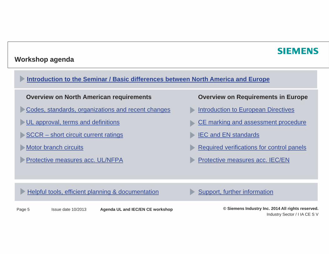
Workshop agenda
Overview on North American requirements
Codes, standards, organizations and recent changes
UL approval, terms and definitions
SCCR – short circuit current ratings
Motor branch circuits
Protective measures acc. UL/NFPA
Introduction to the Seminar / Basic differences between North America and Europe
Helpful tools, efficient planning & documentation Support, further information
Overview on Requirements in Europe
Introduction to European Directives
CE marking and assessment procedure
IEC and EN standards
Required verifications for control panels
Protective measures acc. IEC/EN
© Siemens Industry Inc. 2014 All rights reserved.Industry Sector / I IA CE S V
Page 6 Issue date 10/2013 Agenda UL and IEC/EN CE workshop
Now you certainly have questions ...
© Siemens Industry Inc. 2014. All rights reserved.
Gerhard FlierlSiemens Industry Inc. Industrial Automation
5300 Triangle ParkwayNorcross 30092, Atlanta / GA
Phone: +1 (770) 871-3835Cell Phone: +1 (404) 434-6403
E-mail: [email protected]
Thank you for your attention!
© Siemens Industry Inc. 2014. All rights reserved.
- Introduction to the workshop- Basic differences between North
America and Europe
Why this seminar?Seminar objectivesBasic differences between North America and Europe
© Siemens Industry Inc. 2014. All rights reserved.Industry Sector / I IA CE S VPage 2 01/2013 Introduction, Basic differences
Why this seminar?
Increasing confusion and uncertainty when deciding which European Directives are important for control panel design
Which standards are important for control panel design and how can these be fulfilled?
Uncertainty with regard to the question: "Who holds the responsibility?"
How should the documentation be produced?
What is the distinction between the important Machinery directive [MD] 2006/42/EC and Low-voltage directive [LVD] 2006/95/EC ?
To what extent is the EMC directive 2004/108/EC for control panel design important?

© Siemens Industry Inc. 2014. All rights reserved.Industry Sector / I IA CE S VPage 3 01/2013 Introduction, Basic differences
Seminar objectives
Overview and introduction to European Directives and standards
Refresher and update for the relevant North American standards (UL/NFPA)
To provide assistance and support in understanding important European Directives and standards
To clarify the relationships between relevant standards and their significance for control panel design
To perform the required verifications of the control panel as per IEC 61439-1 & -2
Suggestions for practical documentation that conforms to North American and IEC/EN standards and European Directives
© Siemens Industry Inc. 2014. All rights reserved.Industry Sector / I IA CE S VPage 4 01/2013 Introduction, Basic differences
The importance of standards
In general, standards are:
Standards are not laws – yet they are followed willingly and strictly. When they are followed they are similar to laws
Reflect rules / the state of technology and are considered a proven method in the respective field of application
A support function used to achieve a minimum level of procedure (in different countries, etc.)
Fulfilling standards is not an achievement – it is the minimum expected
The highest protection objectives of standards are: the safety of people, livestock, and property
© Siemens Industry Inc. 2014. All rights reserved.Industry Sector / I IA CE S VPage 5 01/2013 Introduction, Basic differences
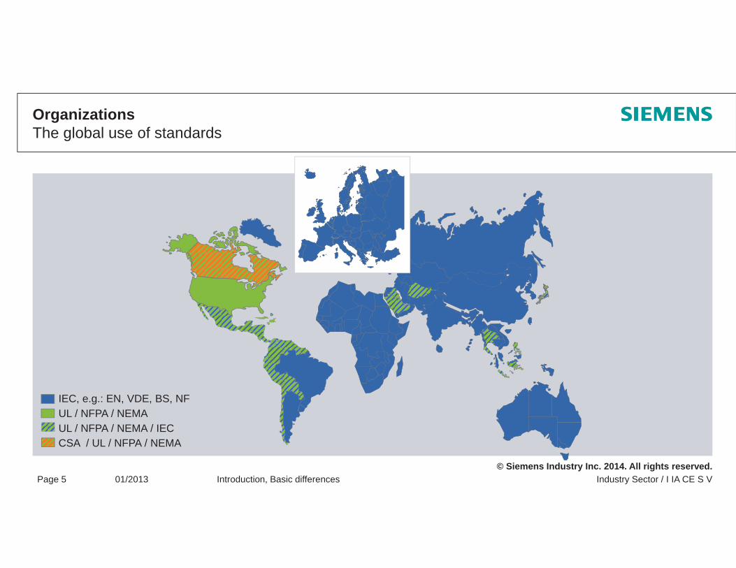
OrganizationsThe global use of standards
IEC, e.g.: EN, VDE, BS, NFUL / NFPA / NEMAUL / NFPA / NEMA / IECCSA / UL / NFPA / NEMA

© Siemens Industry Inc. 2014. All rights reserved.Industry Sector / I IA CE S VPage 6 01/2013 Introduction, Basic differences
Differences between Europe & North America
+ Operating permission of AHJ
EuropeResponsibility of the equipment manufacturer
Responsibility of the operator/user
Protection targets are defined by directives
Presumption of conformity with the application of harmonized standards (ISO9000 et seqq., self-certification, self-responsibility)
USA / North AmericaResponsibility of the operator/user
Protection targets and requirements are defined by laws
Certification/listing of products
Verification by independent NRTL/AHJ (Electrical Inspector) (third-party certification)

© Siemens Industry Inc. 2014. All rights reserved.Industry Sector / I IA CE S VPage 7 01/2013 Introduction, Basic differences
Extracts of the OSHA standards and NEC Ed. 2014
OSHA 1910.303(b)(2) Subpart S – Electrical / General requirements:
Installation and use: Listed or labeled equipment shall be installed and used in accordance with any instructions included in the listing or labeling.
Definitions acc. NEC Art. 100:
Equipment: A general term, including fittings, devices, appliances, luminaires, apparatus, machinery, and the like used as a part of, or in connection with, an electrical installation.
Listed: Equipment, materials, or services included in a list published by an organization that is acceptable to the authority having jurisdiction and concerned with evaluation of products or services, that maintains periodic inspection of production of listed equipment or materials or periodic evaluation of services, and whose listing states that either the equipment, material, or service meets appropriate designated standards or has been tested and found suitable for a specified purpose.
Labeled: Equipment or materials to which has been attached a label, symbol, or other identifying mark ofan organization that is acceptable to the authority having jurisdiction and concerned with product evaluation, that maintains periodic inspection of production of labeled equipment or materials, and by whose labeling the manufacturer indicates compliance with appropriate standards…etc.

© Siemens Industry Inc. 2014. All rights reserved.Industry Sector / I IA CE S VPage 8 01/2013 Introduction, Basic differences
Basic differences between U.S. and CE Markets Standards – Comparison between USA and IEC
IEC 60947IEC 61008
IEC 60204-1IEC 61439-1
IEC 60204-1 IEC 61439-1
© Siemens Industry Inc. 2014. All rights reserved.Industry Sector / I IA CE S VPage 9 01/2013 Introduction, Basic differences
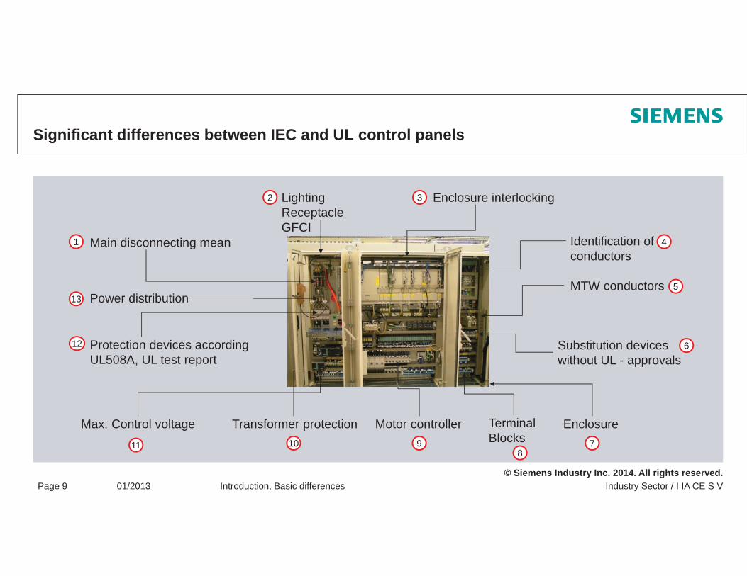
Significant differences between IEC and UL control panels
Main disconnecting mean
LightingReceptacleGFCI
Enclosure interlocking
MTW conductors
Identification ofconductors
Substitution deviceswithout UL - approvals
EnclosureTerminalBlocks
Motor controllerMax. Control voltage
Protection devices accordingUL508A, UL test report
Power distribution
Transformer protection
1
2 3
4
5
6
78
91011
12
13

© Siemens Industry Inc. 2014. All rights reserved.
Questions?

© Siemens Industry Inc. 2014. All Rights Reserved.
Codes, standards and organizations
OrganizationsStandards and CodesRecent changes in the codes and standards

© Siemens Industry Inc. 2014. All Rights Reserved.Industry SectorPage 2 Issue date 10/2013 Codes, Standards and Organizations
Standard Organizations – extract
NFPA:The National Fire Protection Association publishes diverse regulations and directives such as NEC, NFPA79; NFPA70E; NFPA70B
ANSI:The American National Standards Institute is the highest level national standard authority in the USA. Most regulations are based on the ANSI standard
UL:Underwriter Laboratories publishes standards and certifies products in accordance with its own and other standards (CSA, IEC,...). Headquarter: Northbrook, Illinois. In general, UL certification is not required by law. However, all Authoritiesaccept UL certification without restrictions.
CSA:The Canadian Standard Association publishes standards and certifies products in accordance with its own and other standards (UL, IEC,...). Headquarter: Toronto

© Siemens Industry Inc. 2014. All Rights Reserved.Industry SectorPage 3 Issue date 10/2013 Codes, Standards and Organizations
OrganizationsThe origin of UL
1893 World Exhibition in Chicago
Outbreak of a fire
1894 Start of UL
William H. Merrill opens the “Underwriters Electrical Bureau”

© Siemens Industry Inc. 2014. All Rights Reserved.Industry SectorPage 4 Issue date 10/2013 Codes, Standards and Organizations
NFPA Organization
Foundation: 1896, due to increasing sprinkler system installations Headquarters: Quincy, MassachusettsPublication of over 300 standards to date
National Electrical Codeor
NFPA70
NFPA79Electrical Standard for
Industrial Machinery
Standardization organization in the field of fire protection, electrical safety and building safety

© Siemens Industry Inc. 2014. All Rights Reserved.Industry SectorPage 5 Issue date 10/2013 Codes, Standards and Organizations
NRTLs According to OSHAExcerpt from www.osha.gov/dts/otpca/nrtl

© Siemens Industry Inc. 2014. All Rights Reserved.Industry SectorPage 6 Issue date 10/2013 Codes, Standards and Organizations
Important Standards for OEMs and Industrial Control Panel Manufacturers
National Electrical Codeor
NFPA70
NFPA79Industrial Machinery
UL508AIndustrial Control Panels
NEC is the only statutory standard in the USA
UL508A and NFPA79 have a quasi-legislative character

© Siemens Industry Inc. 2014. All Rights Reserved.Industry SectorPage 7 Issue date 10/2013 Codes, Standards and Organizations
Standard References in the USA
NEC (NFPA 70) 2014
UL508A (Industrial Control Panels)
NFPA 79 (Electrical Standard for Industrial Machinery)
Art. 409.1 Scope Safety Standard for Industrial Control Panels
Chapt.65.1 These requirements cover industrial control panelfor industrial machinery.
Art. 670 Electrical Standard for Industrial Machinery

© Siemens Industry Inc. 2014. All Rights Reserved.Industry SectorPage 8 Issue date 10/2013 Codes, Standards and Organizations
StandardsDefinition “Industrial Control Panels” in acc. with NEC 2011
Definition:
2 or more devices installed in the power circuit including their control circuits and control devices
e.g. motor starterComponents suitable for an Industrial Control Panel UL508A, Table SA1.1

© Siemens Industry Inc. 2014. All Rights Reserved.Industry SectorPage 9 Issue date 10/2013 Codes, Standards and Organizations
Application of the wrong standard
… includes the following … does not include the following
- Industrial Control Panels
- Flame Control Panels
- Industrial Machinery
- Crane Control
- Air Conditioning and Refrigerating Equipment
- Service Equipment
- Industrial Control Panel Enclosures
- Irrigation Equipment
- Panels for Construction Sites
- Motor Control Center
- Panels for Classified Locations
- Switchgear (UL891)
- Control Panels for Wind Mills or photovoltaic
- Control Panels for Swimming Pools
- Alarmpanels
- Fire Pump Stations
Example: Scope of the UL508A…
© Siemens Industry Inc. 2014. All Rights Reserved.Industry SectorPage 10 Issue date 10/2013 Codes, Standards and Organizations
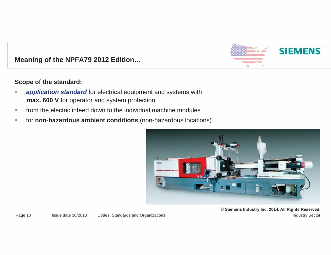
Meaning of the NPFA79 2012 Edition…
Scope of the standard:…application standard for electrical equipment and systems with
max. 600 V for operator and system protection…from the electric infeed down to the individual machine modules…for non-hazardous ambient conditions (non-hazardous locations)

© Siemens Industry Inc. 2014. All Rights Reserved.Industry SectorPage 11 Issue date 10/2013 Codes, Standards and Organizations
Industrial Machinery
Definition of "industrial machinery" according to NFPA79 & NEC70:Motorized machine(s) for material processing (e.g. forming, pressing, cutting)Not transportable by hand during operation With corresponding modules, as the case may be (e.g. conveyor belts, mounting accessories, testing equipment, packing units) Including control technology with PLC controls, actuators / sensors
Definition of "industrial machinery" according to UL508A §65:Metal-processing machinesPlastic-processing machines Wood-processing machinesMounting machinesMaterial-handling machinesMaintenance and testing equipment

© Siemens Industry Inc. 2014. All Rights Reserved.Industry SectorPage 12 Issue date 10/2013 Codes, Standards and Organizations
Examples of Industrial Machines Covered by NFPA79 – Annex C

© Siemens Industry Inc. 2014. All Rights Reserved.Industry SectorPage 13 Issue date 10/2013 Codes, Standards and Organizations
Example of the scope of application standards
NEC (NFPA70)
*)
*)
*)
*)
*)
*) UL508A
NFPA79

© Siemens Industry Inc. 2014. All Rights Reserved.Industry SectorPage 14 Issue date 10/2013 Codes, Standards and Organizations
Definition of TermsAHJ
Authorities Having Jurisdiction (AHJ’s):Compliance with laws and codes is monitored by the responsible authorities of the respective federal states, districts or municipalitiesExample: State Electrical Commission, State Fire MarshalThe current NEC (National Electrical Code) serves as reference in most cases
© Siemens Industry Inc. 2014. All Rights Reserved.Industry SectorPage 15 Issue date 10/2013 Codes, Standards and Organizations
Extracts from the "Electrical Inspection Manual"
Approved:Acceptable to the authority having jurisdiction. [Approval is a primary responsibility of an electrical inspector. Investigations by a thirdparty and the listing and labeling that result are a great aid to inspectors in this responsibility (see "Labeled„ and"Listed").]
The inspector decides on what is and what is not accepted; UL approvals serve as a great help and reference for the inspector
AHJ function:The key to a successful and correct electrical inspection lies in applying therules of the Code, not the personal preferences of the inspector. To reiterate, if the installation meets the Code requirements (including any local amendments) and is safe, the installation should pass inspection.
The application of standards facilitates acceptance by the inspector
© Siemens Industry Inc. 2014. All Rights Reserved.Industry SectorPage 16 Issue date 10/2013 Codes, Standards and Organizations
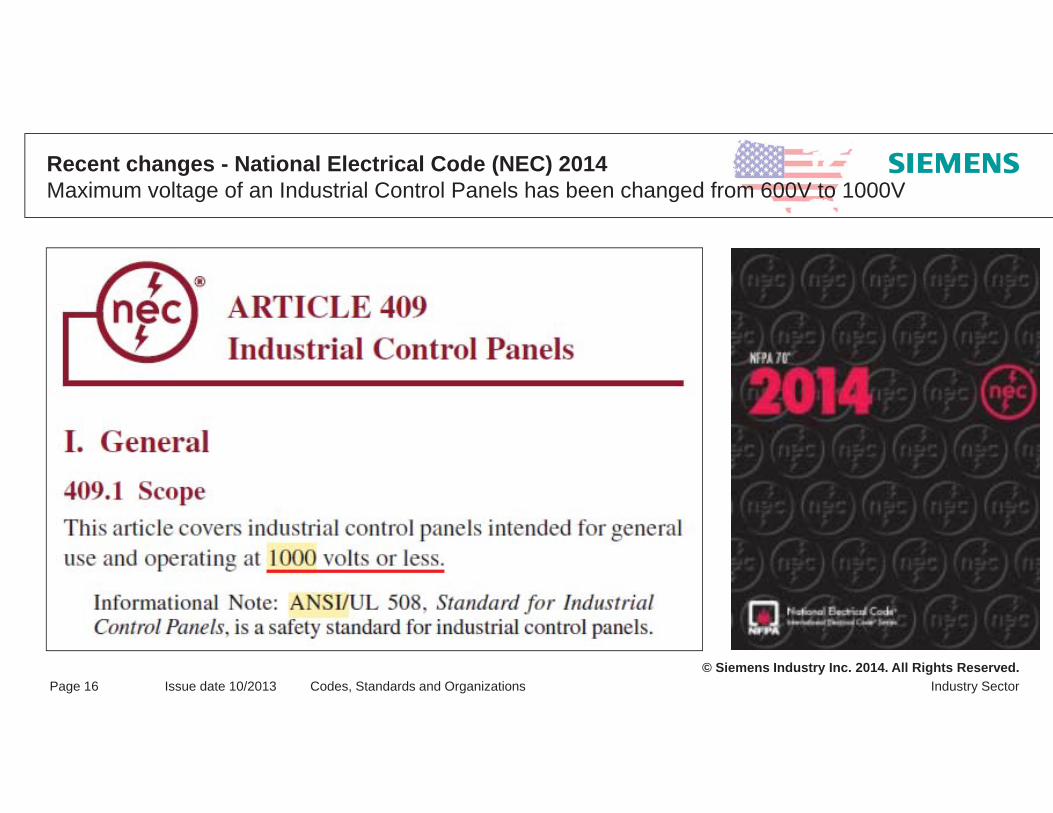
Recent changes - National Electrical Code (NEC) 2014Maximum voltage of an Industrial Control Panels has been changed from 600V to 1000V

© Siemens Industry Inc. 2014. All Rights Reserved.Industry SectorPage 17 Issue date 10/2013 Codes, Standards and Organizations
Recent changes - National Electrical Code (NEC) 2014Maximum voltage of an Industrial Control Panels has been changed
When it comes to Industrial control panels the NEC 2014 refers still to UL 508A!
Recommendation:
Industrial control Panels should fulfill furthermore the UL 508A
Maximum voltage 600V!
UL 508A is still limited to 600V or less!
© Siemens Industry Inc. 2014. All Rights Reserved.Industry SectorPage 18 Issue date 10/2013 Codes, Standards and Organizations
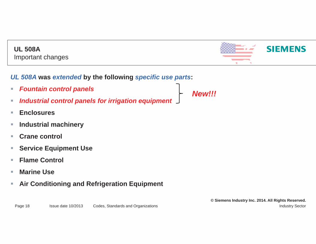
UL 508AImportant changes
UL 508A was extended by the following specific use parts:
Fountain control panels
Industrial control panels for irrigation equipment
Enclosures
Industrial machinery
Crane control
Service Equipment Use
Flame Control
Marine Use
Air Conditioning and Refrigeration Equipment
New!!!

© Siemens Industry Inc. 2014. All Rights Reserved.Industry SectorPage 19 Issue date 10/2013 Codes, Standards and Organizations
Definition of TermsListings / Symbols
UL „listed“ Markfor USA andCanada
UL „classified“Mark for USA and
Canada
UL „enhanced“Mark for USA and
Canada
Notes: - Long transition time (approx. 10 years)- The current “classified” and “listed” marks will not expire

© Siemens Industry Inc. 2014. All Rights Reserved.Industry SectorPage 20 Issue date 10/2013 Codes, Standards and Organizations
NEC Ed. 2014 Important changes – Spacings for Industrial Control Panels
409.106 SpacingsSpacings in feeder circuits between uninsulated live parts of adjacent components, between uninsulated live parts of components and grounded or accessible non–current-carrying metal parts, between uninsulated live parts of components and the enclosure, and at field wiring terminals shall be as shown in Table 430.97(D).
Exception: Spacings shall be permitted to be less than those specified in Table 430.97(D) at circuit breakers and switches and in listed components installed in industrial control panels.

© Siemens Industry Inc. 2014. All Rights Reserved.Industry SectorPage 21 Issue date 10/2013 Codes, Standards and Organizations
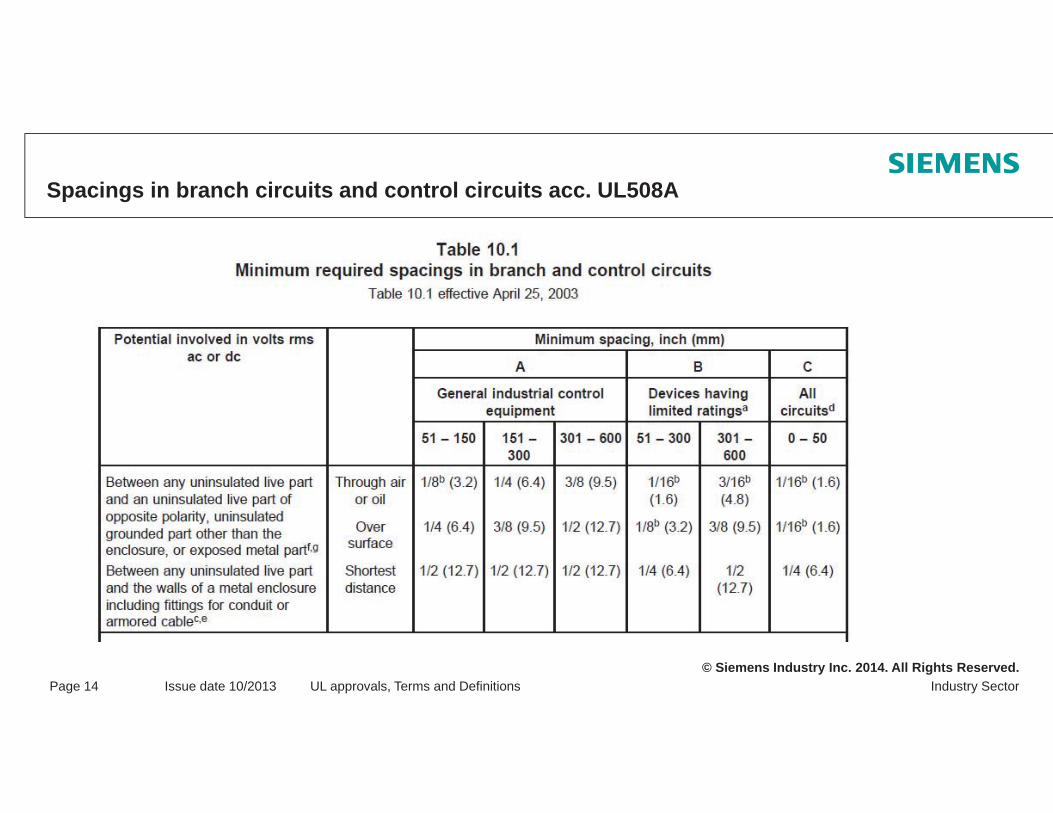
NEC Ed. 2014 Spacings in branch circuits and control circuits acc. UL508A

© Siemens Industry Inc. 2014. All Rights Reserved.Industry SectorPage 22 Issue date 10/2013 Codes, Standards and Organizations
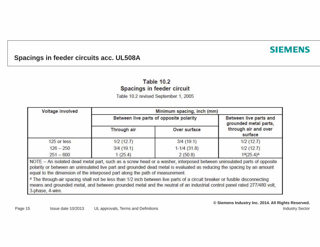
NEC Ed. 2014 Spacings in feeder circuits acc. UL508A
© Siemens Industry Inc. 2014. All Rights Reserved.Industry SectorPage 23 Issue date 10/2013 Codes, Standards and Organizations
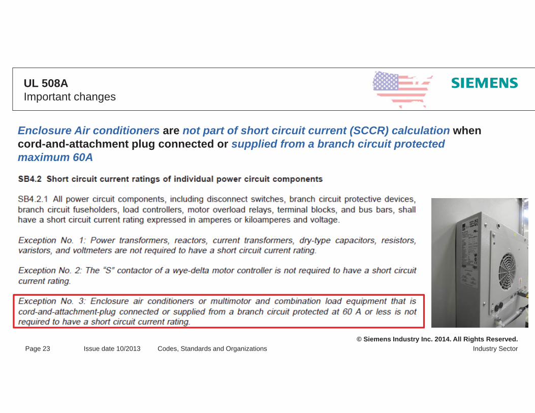
UL 508AImportant changes
Enclosure Air conditioners are not part of short circuit current (SCCR) calculation when cord-and-attachment plug connected or supplied from a branch circuit protected maximum 60A

© Siemens Industry Inc. 2014. All Rights Reserved.Industry SectorPage 24 Issue date 10/2013 Codes, Standards and Organizations
UL 508AImportant changes
Main Disconnect
contactor contactor
motor heater
Overload-relay
contactor
motor
Overload-relay
Every Transformer is current limiting
Short circuit protection Short circuit protection Short circuit protection
Feeder circuit
Branch circuit
Current limitingdevice
Transformer peak-let-through currents can be used to protect Branch circuits!
© Siemens Industry Inc. 2014. All Rights Reserved.Industry SectorPage 25 Issue date 10/2013 Codes, Standards and Organizations
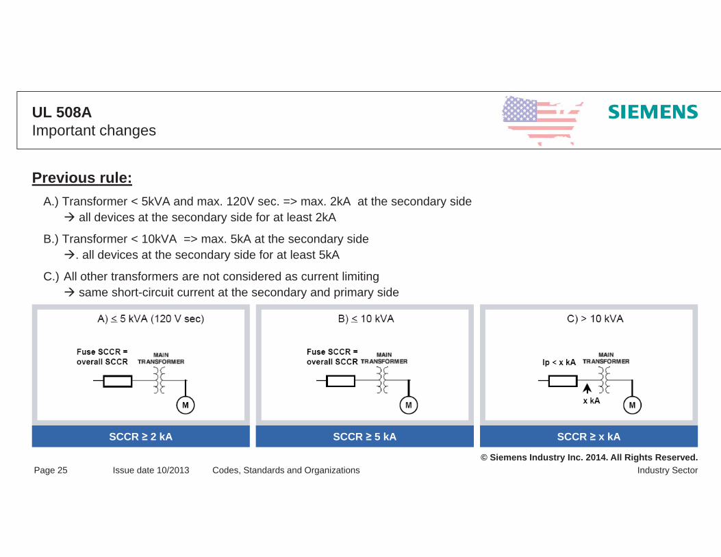
UL 508AImportant changes
Previous rule:A.) Transformer < 5kVA and max. 120V sec. => max. 2kA at the secondary side
all devices at the secondary side for at least 2kA
B.) Transformer < 10kVA => max. 5kA at the secondary side. all devices at the secondary side for at least 5kA
C.) All other transformers are not considered as current limitingsame short-circuit current at the secondary and primary side
SCCR 2 kA SCCR 5 kA SCCR x kA

© Siemens Industry Inc. 2014. All Rights Reserved.Industry SectorPage 26 Issue date 10/2013 Codes, Standards and Organizations
New rule:Loads provided by a Transformer with isolated secondary acc. to UL 508A SB4.3.1Possibility 1: For transformer with marked or known impedance (Z acc. To UL 508A), the maximum secondary short circuit current will be calculated as follows:
All devices located at transformer secondary shall be the calculated short circuit current rating (Isc)SCCR of the loads = Interrupting rating of primary overcurrent protection device
UL 508AImportant changes

© Siemens Industry Inc. 2014. All Rights Reserved.Industry SectorPage 27 Issue date 10/2013 Codes, Standards and Organizations
New rule:Loads provided by a Transformer with isolated secondary acc. to UL 508A SB4.3.1Possibility 2: For transformer with unknown impedance (Z acc. To UL 508A) or 2,1%, the maximum secondary short circuit current will be calculated as in possibility 1 described (assumption Z = 2,1 %) or determined with Table SB4.3 (single phase) respectively SB4.4 (three phase) as follows:1. Transformer kVA maximum value column 1 and2. Secondary voltage not smaller as values in column 2. If the secondary voltage is between the values, the next smaller voltage shall be used.
Table SB4.3 Table SB4.4
UL 508AImportant changes

© Siemens Industry Inc. 2014. All Rights Reserved.Industry SectorPage 28 Issue date 10/2013 Codes, Standards and Organizations
UL 508AImportant changes
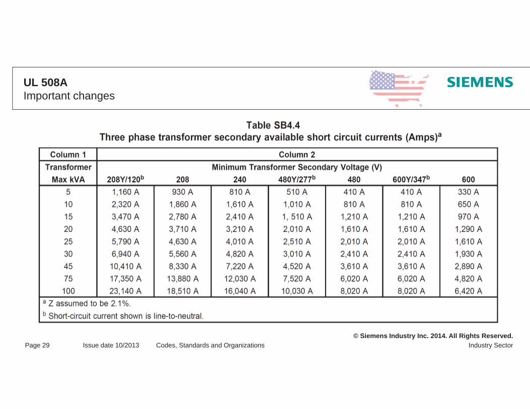
© Siemens Industry Inc. 2014. All Rights Reserved.Industry SectorPage 29 Issue date 10/2013 Codes, Standards and Organizations
UL 508AImportant changes

© Siemens Industry Inc. 2014. All Rights Reserved.Industry SectorPage 30 Issue date 10/2013 Codes, Standards and Organizations
UL 508AImportant changes
Sizing of branch-circuit protection of a variable speed drive if not specified by the manufacturer instruction
Up to now
As of now

© Siemens Industry Inc. 2014. All Rights Reserved.Industry SectorPage 31 Issue date 10/2013 Codes, Standards and Organizations
UL 508AImportant changes
Protection devices in dc control circuits above 32V shall be approved for the rating equal or greater
Excerpt from Certificate of compliance of Siemens supplementary protectors 5SY…

© Siemens Industry Inc. 2014. All Rights Reserved.Industry SectorPage 32 Issue date 10/2013 Codes, Standards and Organizations
NFPA 79 Ed. 2012Grounding
NFPA79 Ed. 20078.2.3.1 The continuity of the equipment groundling (protective bonding) circuit shall be ensured by effective connections through conductors or structural members.
NFPA79 Ed. 20128.2.3.1 The continuity of the equipment grounding (protective bonding) circuit shall be ensured by effective connections through conductors

© Siemens Industry Inc. 2014. All Rights Reserved.
Thank you for your attention!Questions?

© Siemens Industry Inc. 2014. All Rights Reserved.
UL Approvals, Terms and Definitions
DefinitionsTerms and their backgroundMarkings

© Siemens Industry Inc. 2014. All Rights Reserved.Industry SectorPage 2 Issue date 10/2013 UL approvals, Terms and Definitions
Definition of TermsListings / Symbols
Application of these products requires the so-called CoAs (Conditions of Acceptability)
The installer requires "special" instructions = engineering supervision
UL certificates (CoC’s) include the ‘Conditions of Accesptability’ or www.ul.com/database

© Siemens Industry Inc. 2014. All Rights Reserved.Industry SectorPage 3 Issue date 10/2013 UL approvals, Terms and Definitions
Definition of TermsListings / Symbols
UL „listed“ Markfor USA andCanada
UL „classified“Mark for USA and
Canada
UL „enhanced“Mark for USA and
Canada

© Siemens Industry Inc. 2014. All Rights Reserved.Industry SectorPage 4 Issue date 10/2013 UL approvals, Terms and Definitions
Definition of TermsUL Product Categories
The CCN represents a clear description of the respective productThe respective CCN Guide Information clearly describes how and under which conditions the respective product can or may be applied (www.ul.com/database)Every AHJ or UL inspector can thus verify whether the respective product was correctly configured and appliedThe CCN should be additionally integrated in the parts list
Examples: DIVQ // DIVQ7 // NMTR2 // NMTR8

© Siemens Industry Inc. 2014. All Rights Reserved.Industry SectorPage 5 Issue date 10/2013 UL approvals, Terms and Definitions
Definition of TermsUL Product Categories
Definition of the CCN (Category Code Number):Numerical or alphanumerical character string for the exact identification of products according to UL standards!
Product Contactors(magnetic motor controllers)
Overcurrent relays(overload relays)
Standard UL508 – Industrial Control Equipment
UL-ListedNLDX NKCR
UL-RecognizedNLDX2 NKCR2
Example:

© Siemens Industry Inc. 2014. All Rights Reserved.Industry SectorPage 6 Issue date 10/2013 UL approvals, Terms and Definitions
SA1 list – UL508A

© Siemens Industry Inc. 2014. All Rights Reserved.Industry SectorPage 7 Issue date 10/2013 UL approvals, Terms and Definitions
Definition of Terms
Excerpt from NFPA 79 Mandatory!
Recommendation!
UL terms cannot be converted one to one to IEC standards, they must be questioned!
Factory wiring = internal wiring = all components inside the industrial control panelthe installer works under "engineering" supervision UL508A , § 29
Field wiring = all components inserted from the outsidethe installer implements his own professional know-how UL508A, § 28
Overcurrent = NEC Art. 100overload and/or short circuit current and/or, where applicable, ground fault current

© Siemens Industry Inc. 2014. All Rights Reserved.Industry SectorPage 8 Issue date 10/2013 UL approvals, Terms and Definitions
Factory / Field WiringExample – Excerpt from UL Database (www.ul.com/database)
Power distribution block5ST25..CCN: XCFR2E-file: E80027
Code 1: Only factory wiring Code 2: Factory and field wiringUL-listed products always feature a field wiring approval!

© Siemens Industry Inc. 2014. All Rights Reserved.Industry SectorPage 9 Issue date 10/2013 UL approvals, Terms and Definitions
Definition of Terms Persons
Electrically instructed personElectr. hazards / risks can be avoided through appropriate instruction or supervision
Electrically skilled personElectr. risks can be detected and hazards avoided through appropriate training and experience
Qualified personKnowledge and skills regarding the design and operation of electrical equipment Safety training on the respective hazards (NEC 2008 Handbook Art. 100)

© Siemens Industry Inc. 2014. All Rights Reserved.Industry SectorPage 10 Issue date 10/2013 UL approvals, Terms and Definitions
Overview and Definition
Definitions acc. UL508A:
Feeder circuit:Definition: FEEDER CIRCUIT – The conductors and circuitry on the supply side of the branch circuit
overcurrent protective device.
FCPD’s: UL489 (3WL; 3VL; 3RV17/18; 5SJ4…-.HG)
UL248-4…-12 (3NW; Class CC)
UL98
Branch circuit:Definition: BRANCH CIRCUIT – The conductors and components following the last overcurrent
protective device protecting a load.BCPD’s: Depending on application case

© Siemens Industry Inc. 2014. All Rights Reserved.Industry SectorPage 11 Issue date 10/2013 UL approvals, Terms and Definitions
Overview and Definition
-M1 -M2
-DISC
-CON1-OL1
-FU1-FU2
-CON2-OL2
-T
-FU3
Control Circuit
Viewing Direction
Boundary Feeder and Branch

© Siemens Industry Inc. 2014. All Rights Reserved.Industry SectorPage 12 Issue date 10/2013 UL approvals, Terms and Definitions
Distance through air and over surface
Depending on voltage up to1 inch – distance through air2 inches – distance over surface
Overview and DefinitionPractical realization
0 – 125 V 126 – 250 V 251 – 600 VIndication of the distances between the current-carrying wires and enclosure and the distances through air and over surface
Feeder circuits:
Branch circuits: see UL 508A table 10.1
or
0 – 50 V 51 – 150 V 151 – 300 V 301 – 600 VIndication of the distances between current-carrying wires and enclosures and the distances through air and over surface
UL 489UL 98UL 248
Distribution
Circuit Breaker
Line Terminals
Load Terminals
Motors Trans-former Heater
Feed
er C
ircui
tB
ranc
h C
ircui
tsee UL 508A table 10.2

© Siemens Industry Inc. 2014. All Rights Reserved.Industry SectorPage 13 Issue date 10/2013 UL approvals, Terms and Definitions
NEC 2014 – Spacings for Industrial Control Panels
409.106 SpacingsSpacings in feeder circuits between uninsulated live parts of adjacent components, between uninsulated live parts of components and grounded or accessible non–current-carrying metal parts, between uninsulated live parts of components and the enclosure, and at field wiring terminals shall be as shown in Table 430.97(D).
Exception: Spacings shall be permitted to be less than those specified in Table 430.97(D) at circuit breakers and switches and in listed components installed in industrial control panels.
© Siemens Industry Inc. 2014. All Rights Reserved.Industry SectorPage 14 Issue date 10/2013 UL approvals, Terms and Definitions
Spacings in branch circuits and control circuits acc. UL508A
© Siemens Industry Inc. 2014. All Rights Reserved.Industry SectorPage 15 Issue date 10/2013 UL approvals, Terms and Definitions
Spacings in feeder circuits acc. UL508A

© Siemens Industry Inc. 2014. All Rights Reserved.Industry SectorPage 16 Issue date 10/2013 UL approvals, Terms and Definitions
Overview and requirements
There are different type of power supply networks in North America in regards to their- design (e.g. wye, delta)- grounding (ungrounded, grounded, high impedance grounded)
Generally, all voltages occurring in these network types are indicated (phase to phase / phase to ground)
Also the ground connection and the circuit on the secondary side of the transformer are indicated
Abbreviations and Indictaions of number of wires:Number of phase wires: “phase”, “p”, or “ ”Total number of wires: “wire” or “w”
Example of voltage ratings:slash rating: 480Y/277V; 3 4wstraight rating: 480V; 3p; 3w
© Siemens Industry Inc. 2014. All Rights Reserved.Industry SectorPage 17 Issue date 10/2013 UL approvals, Terms and Definitions
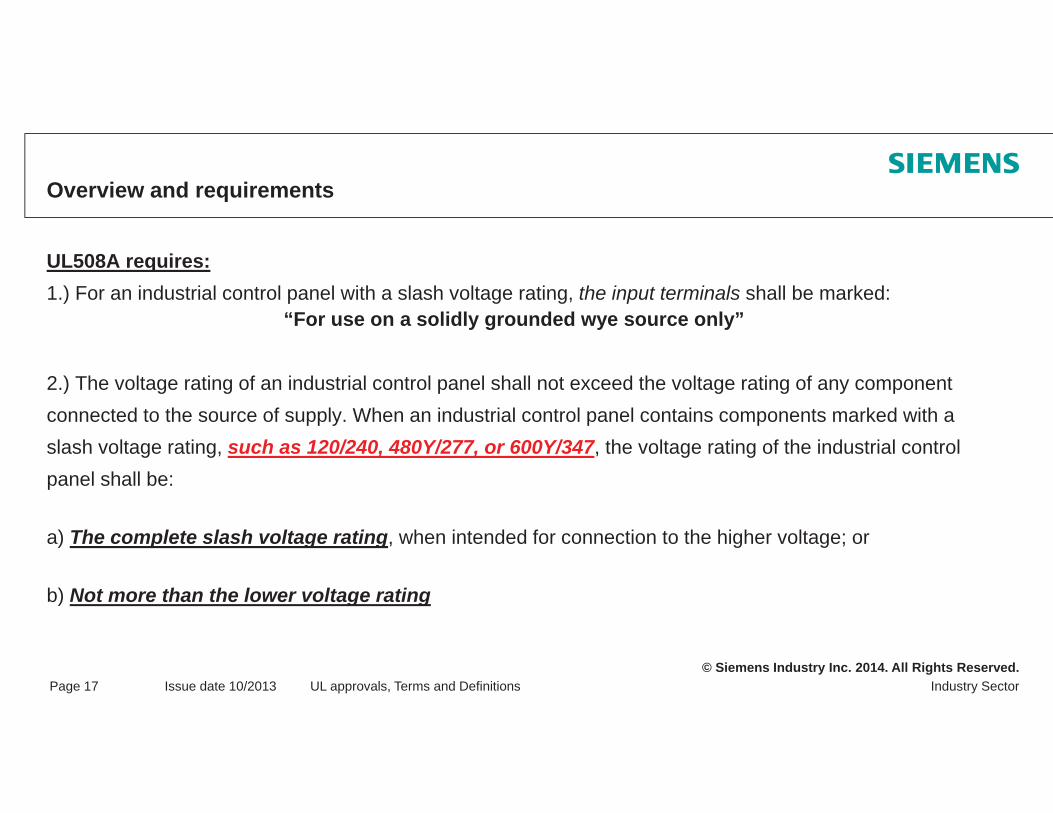
Overview and requirements
UL508A requires:1.) For an industrial control panel with a slash voltage rating, the input terminals shall be marked:
“For use on a solidly grounded wye source only”
2.) The voltage rating of an industrial control panel shall not exceed the voltage rating of any componentconnected to the source of supply. When an industrial control panel contains components marked with aslash voltage rating, such as 120/240, 480Y/277, or 600Y/347, the voltage rating of the industrial controlpanel shall be:
a) The complete slash voltage rating, when intended for connection to the higher voltage; or
b) Not more than the lower voltage rating

© Siemens Industry Inc. 2014. All Rights Reserved.Industry SectorPage 18 Issue date 10/2013 UL approvals, Terms and Definitions
Overview and requirements
NFPA79 requires:
A circuit breaker, self-protected combination motor, controller, or a manual motor controller markedwith a slash rating, such as 120/240V or 480Y/277V, shall be applied in a solidly grounded circuit where:
- the nominal voltage of any conductor to ground does not exceed the lower voltage rating - and the nominal voltage between any two conductors does not exceed the higher voltage rating.
When slash-rated devices are connected to the supply circuit of the machine, the nameplate voltage rating shall not exceed the lower voltage rating or shall include the complete slash rating.

© Siemens Industry Inc. 2014. All Rights Reserved.Industry SectorPage 19 Issue date 10/2013 UL approvals, Terms and Definitions
Most Important Network Types in DetailGrounded wye / solidly grounded wye
Slash rating:e.g.: 480Y/277V, solidly grounded wye3 phase; 4 wire3 phase; 3 wire
Possible devices480Y/277V; 600/347V480V; 600V
Note:All devices having a slash rating with the indicated voltage or higher
All devices having a straight rating with at least the higher of both voltages
3p, 4w / grounded
phase-ground
U = 277 Vacross one
contactworst case!
L1L2L3
Transformer
480Y/277V AC
M
Ik

© Siemens Industry Inc. 2014. All Rights Reserved.Industry SectorPage 20 Issue date 10/2013 UL approvals, Terms and Definitions
Most Important Network Types in DetailCorner grounded delta
Straight (Delta) rating: e.g.: 480V / 3 phase - 3 wire
Possible devices in this example: 480V; 600V
Do not use: 480Y/277V; 600Y/347V
Note:The devices switch full (=high) voltage at the first single pole short-circuit (phase to ground)
The following applies to this network in principle: Only devices with straight rating must be used!
Phase - Ground
U = 480 Vacross one contact
worst case!!
L1L2L3
Transformer 480V AC
M
Ik
© Siemens Industry Inc. 2014. All Rights Reserved.Industry SectorPage 21 Issue date 10/2013 UL approvals, Terms and Definitions
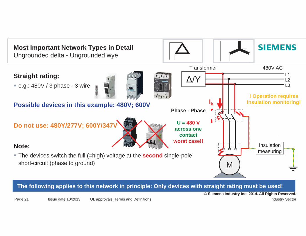
Most Important Network Types in DetailUngrounded delta - Ungrounded wye
Straight rating: e.g.: 480V / 3 phase - 3 wire
Possible devices in this example: 480V; 600V
Do not use: 480Y/277V; 600Y/347V
Note:The devices switch the full (=high) voltage at the second single-pole short-circuit (phase to ground)
The following applies to this network in principle: Only devices with straight rating must be used!
480V ACL1L2L3
Transformer
M
/YBetrieb
Insulation measuring
! Operation requiresInsulation monitoring!Ik
Phase - Phase
U = 480 Vacross one
contactworst case!!

© Siemens Industry Inc. 2014. All Rights Reserved.Industry SectorPage 22 Issue date 10/2013 UL approvals, Terms and Definitions
Agreements Between Manufacturer and Customer
The standard offers support in the form of a ready-made questionnaire in Annex B / NFPA79 (only informative!)

© Siemens Industry Inc. 2014. All Rights Reserved.
Thank you for your attention!Questions?
© Siemens Industry Inc. 2014. All Rights Reserved.
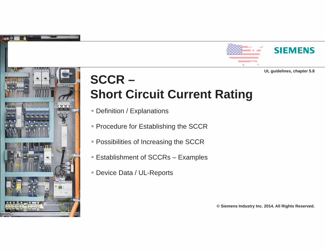
SCCR –Short Circuit Current Rating
Definition / Explanations
Procedure for Establishing the SCCR
Possibilities of Increasing the SCCR
Establishment of SCCRs – Examples
Device Data / UL-Reports
UL guidelines, chapter 5.8

© Siemens Industry Inc. 2014. All Rights Reserved.Industry SectorPage 2 Issue 10/2013 SCCR – Short Circuit Current Rating
Definition / Explanations
Requirement of NEC 2005 Art. 409 (mandatory since April 26, 2006)
Re-enforcement of the standards for “industrial control panels” Failures in determining the short-circuit current rating (= SCCR) of an industrial control panel.
For the short-circuit current rating not only the short-circuit breaking capacity of, e.g. the circuit breaker is needed, also the short-circuit current rating of every individual device is as relevant.
SCCR-relevant components in the main circuit, such as:
Circuit-breakers, contactors, soft starters, overload relays, but also
Terminals, busbars,
Supply to an control transformers,
Frequency converters, …
Further current limiting “effects” are not allowed to be considerede.g.: that of wires, cables, busbars, …
© Siemens Industry Inc. 2014. All Rights Reserved.Industry SectorPage 3 Issue 10/2013 SCCR – Short Circuit Current Rating
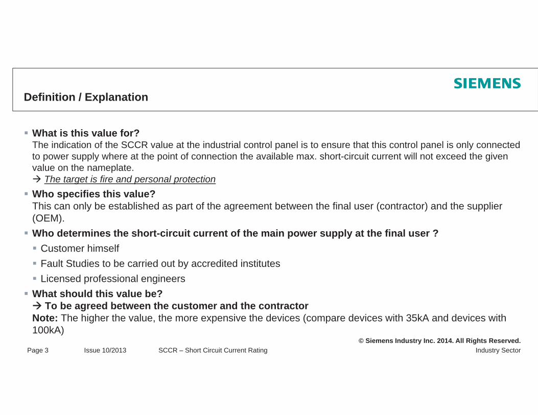
Definition / Explanation
What is this value for?The indication of the SCCR value at the industrial control panel is to ensure that this control panel is only connected to power supply where at the point of connection the available max. short-circuit current will not exceed the given value on the nameplate.
The target is fire and personal protection Who specifies this value?This can only be established as part of the agreement between the final user (contractor) and the supplier (OEM).Who determines the short-circuit current of the main power supply at the final user ?
Customer himselfFault Studies to be carried out by accredited institutesLicensed professional engineers
What should this value be?To be agreed between the customer and the contractor
Note: The higher the value, the more expensive the devices (compare devices with 35kA and devices with 100kA)

© Siemens Industry Inc. 2014. All Rights Reserved.Industry SectorPage 4 Issue 10/2013 SCCR – Short Circuit Current Rating
Procedure for Establishing the SCCR
Determination of the short-circuit current rating (SCCR) acc. to NEC409.110 (4):
Step 1: Has to be!SCCR of the installed and UL-listed components
Step 2: Has to be!Establishment of the SCCR on the basis of standard values(UL508A suppl. SB or UL-guide; chapter 5.8.4).
Step 3: Optional, very helpfull!SCCR of tested industrial control equipment assemblies(series rating = 2 circuit breakers in series or combination tests = motor branch circuits)
Step 4: Optional, not very helpfull!Use of current limiting devices (transformers, fuses, circuit breakers)

© Siemens Industry Inc. 2014. All Rights Reserved.Industry SectorPage 5 Issue 10/2013 SCCR – Short Circuit Current Rating
Establishment of the SCCR value on the basis of the parameters of installed and UL-listed components
Procedure for Establishing the SCCRStep 1
Excerpt of a method description from the “White Paper” by Siemens Energy & Automation (SE&A)
List the short circuit current ratings of components, marked on components or on instructions provided with the components.
© Siemens Industry Inc. 2014. All Rights Reserved.Industry SectorPage 6 Issue 10/2013 SCCR – Short Circuit Current Rating
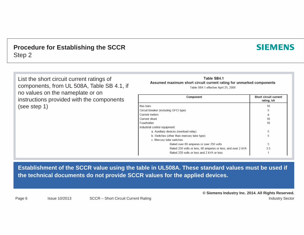
Establishment of the SCCR value using the table in UL508A. These standard values must be used if the technical documents do not provide SCCR values for the applied devices.
Procedure for Establishing the SCCRStep 2
List the short circuit current ratings of components, from UL 508A, Table SB 4.1, if no values on the nameplate or on instructions provided with the components (see step 1)

© Siemens Industry Inc. 2014. All Rights Reserved.Industry SectorPage 7 Issue 10/2013 SCCR – Short Circuit Current Rating
SCCR of tested industrial control equipment assembliesSeries rating testsSeries connection of 2 or more devices, which are able to automatically respond in short circuit cases without delay. SB4.3.2 in UL508A! Current limiting cannot be used here !Combination testsSeries connection of any type of devices, e.g.:
Motor protection circuit breaker and contactor (=fuseless load feeders as type F acc. to UL508)MCCB and terminal block
Procedure for Establishing the SCCRStep 3

© Siemens Industry Inc. 2014. All Rights Reserved.Industry SectorPage 8 Issue 10/2013 SCCR – Short Circuit Current Rating
Procedure for Establishing the SCCRStep 3
MCCB3VL
MCB5SJ4..HG4
M
MCCB3VL
3RBmotor protection relay
3RTcontactor
Fuse
Series rating Tested combinations
MCB5SJ4..HG4

© Siemens Industry Inc. 2014. All Rights Reserved.Industry SectorPage 9 Issue 10/2013 SCCR – Short Circuit Current Rating
Possibilities of Increasing the SCCRStep 4 Use of transformers SB 4.3.1

© Siemens Industry Inc. 2014. All Rights Reserved.Industry SectorPage 10 Issue 10/2013 SCCR – Short Circuit Current Rating
Possibilities of Increasing the SCCRStep 4 Use of transformers SB 4.3.1

© Siemens Industry Inc. 2014. All Rights Reserved.Industry SectorPage 11 Issue 10/2013 SCCR – Short Circuit Current Rating
Possibilities of Increasing the SCCRStep 4 Use of transformers
1.) Single Phase Transformers:Transformer Full-Load Current (IFL) = (Transformer kVA x 1000) / Voltage*
Short Circuit Current (ISC line-to-line) = ((Transformer Full Load Current (IFL )) / Transformer Impedance (Z)
2.) Three Phase Transformers:Transformer Full-Load Current (IFL) = (Transformer kVA x 1000) / (Voltage** x 1.732)
Short Circuit Current (ISC line-to-line-to-line) = ((Transformer Full Load Current(IFL )) / Transformer Impedance (Z)
© Siemens Industry Inc. 2014. All Rights Reserved.Industry SectorPage 12 Issue 10/2013 SCCR – Short Circuit Current Rating
Possibilities of Increasing the SCCRStep 4
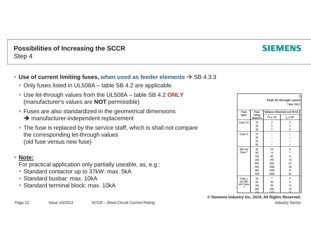
Use of current limiting fuses, when used as feeder elements SB 4.3.3Only fuses listed in UL508A – table SB 4.2 are applicable.Use let-through values from the UL508A – table SB 4.2 ONLY(manufacturer‘s values are NOT permissible)Fuses are also standardized in the geometrical dimensions
manufacturer-independent replacementThe fuse is replaced by the service staff, which is shall not compare the corresponding let-through values (old fuse versus new fuse)
Note:For practical application only partially useable, as, e.g.:
Standard contactor up to 37kW: max. 5kAStandard busbar: max. 10kAStandard terminal block: max. 10kA

© Siemens Industry Inc. 2014. All Rights Reserved.Industry SectorPage 13 Issue 10/2013 SCCR – Short Circuit Current Rating
Possibilities to Increase the SCCRStep 4
Attention:Here, only the let-through values of UL508A (table SB4.2, §SB4.3.3) have to be used. Let-Through values are peak values. These HAVE TO BE compared with the rms (effective values) of the devices acc. to UL508A.
© Siemens Industry Inc. 2014. All Rights Reserved.Industry SectorPage 14 Issue 10/2013 SCCR – Short Circuit Current Rating
Possibilities of Increasing the SCCRStep 4
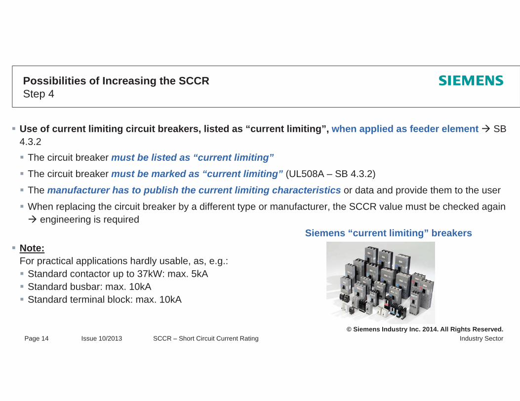
Use of current limiting circuit breakers, listed as “current limiting”, when applied as feeder element SB4.3.2
The circuit breaker must be listed as “current limiting”The circuit breaker must be marked as “current limiting” (UL508A – SB 4.3.2)
The manufacturer has to publish the current limiting characteristics or data and provide them to the user
When replacing the circuit breaker by a different type or manufacturer, the SCCR value must be checked again engineering is required
Note:For practical applications hardly usable, as, e.g.:
Standard contactor up to 37kW: max. 5kAStandard busbar: max. 10kAStandard terminal block: max. 10kA
Siemens “current limiting” breakers
© Siemens Industry Inc. 2014. All Rights Reserved.Industry SectorPage 15 Issue 10/2013 SCCR – Short Circuit Current Rating
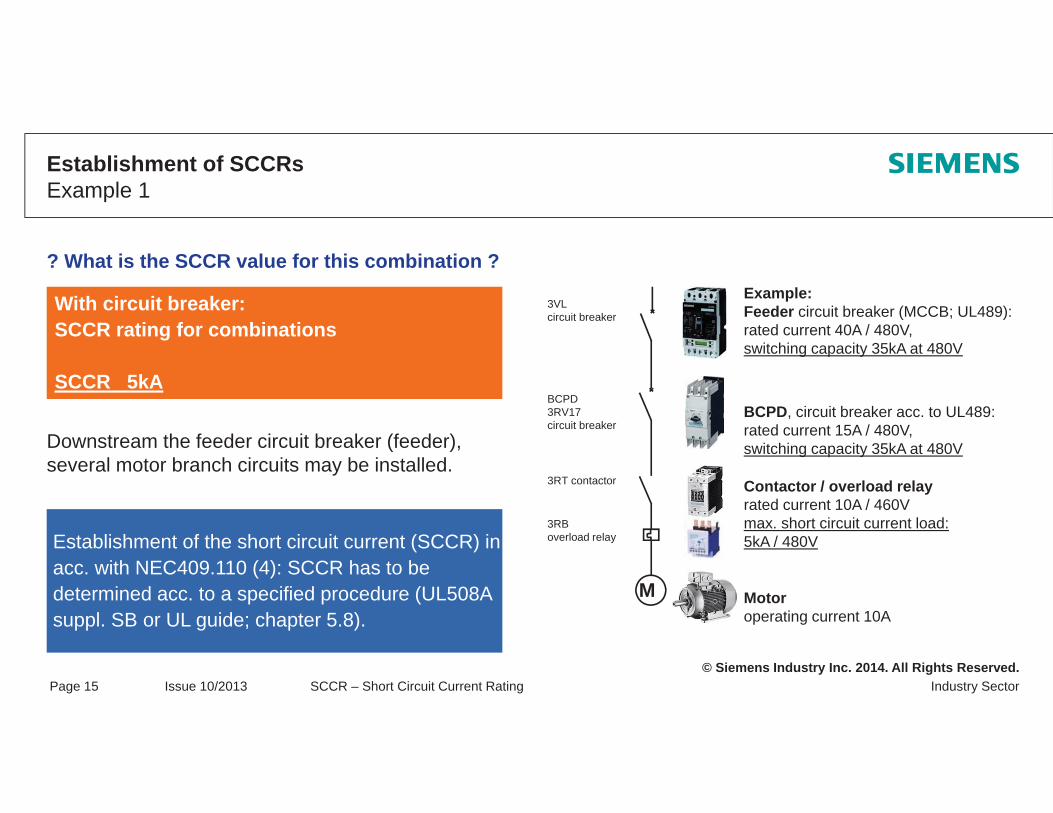
Example:Feeder circuit breaker (MCCB; UL489): rated current 40A / 480V,switching capacity 35kA at 480V
Motoroperating current 10A
Contactor / overload relayrated current 10A / 460Vmax. short circuit current load:5kA / 480V
With circuit breaker:SCCR rating for combinations
SCCR 5kA
3VLcircuit breaker
3RT contactor
3RBoverload relay
BCPD3RV17circuit breaker
BCPD, circuit breaker acc. to UL489: rated current 15A / 480V, switching capacity 35kA at 480VDownstream the feeder circuit breaker (feeder),
several motor branch circuits may be installed.
Establishment of SCCRs Example 1
? What is the SCCR value for this combination ?
M
Establishment of the short circuit current (SCCR) in acc. with NEC409.110 (4): SCCR has to be determined acc. to a specified procedure (UL508A suppl. SB or UL guide; chapter 5.8).
© Siemens Industry Inc. 2014. All Rights Reserved.Industry SectorPage 16 Issue 10/2013 SCCR – Short Circuit Current Rating
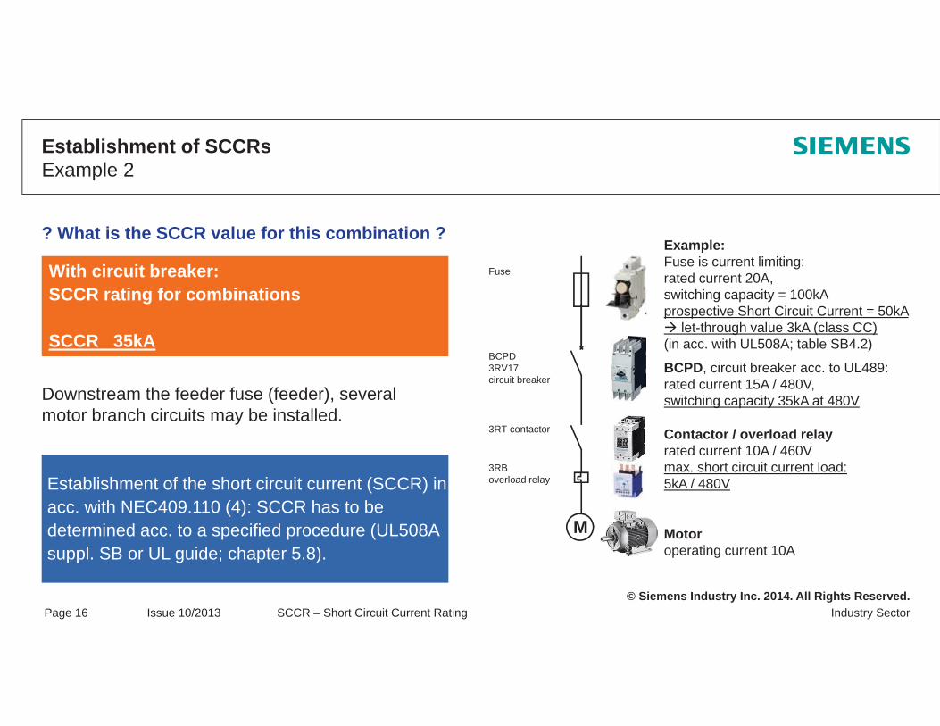
Example:Fuse is current limiting:rated current 20A,switching capacity = 100kAprospective Short Circuit Current = 50kA
let-through value 3kA (class CC)(in acc. with UL508A; table SB4.2)
Motoroperating current 10A
Contactor / overload relayrated current 10A / 460Vmax. short circuit current load:5kA / 480V
With circuit breaker:SCCR rating for combinations
SCCR 35kA
Fuse
3RT contactor
3RBoverload relay
BCPD3RV17circuit breaker
BCPD, circuit breaker acc. to UL489: rated current 15A / 480V, switching capacity 35kA at 480VDownstream the feeder fuse (feeder), several
motor branch circuits may be installed.
Establishment of SCCRs Example 2
? What is the SCCR value for this combination ?
M
Establishment of the short circuit current (SCCR) in acc. with NEC409.110 (4): SCCR has to be determined acc. to a specified procedure (UL508A suppl. SB or UL guide; chapter 5.8).

© Siemens Industry Inc. 2014. All Rights Reserved.Industry SectorPage 17 Issue 10/2013 SCCR – Short Circuit Current Rating
Example:Circuit breaker in acc. with UL489:rated current 30A / 480V, switching capacity 35kA / 480V
Contactor / overload relay rated current 10A / 460Vmax. short circuit current load:5kA / 480V
With circuit breaker:SCCR rating for combinations
SCCR 5kA
Downstream the feeder circuit breaker (feeder), several motor branch circuits may be installed.
Establishment of SCCRsExample 3
? What is the SCCR value for this combination ?
M
Establishment of the short circuit current (SCCR) in acc. with NEC409.110 (4): SCCR has to be determined acc. to a specified procedure (UL508A suppl. SB or UL guide; chapter 5.8).
3RV17circuit breaker
3RT contactor
3RBoverload relay
Fuse
Motoroperating current 10A
Fuse is current limiting:rated current 20A,switching capacity = 100kAprospective Short Circuit Current = 50kA
let-through value 3kA (class CC)(in acc. with UL508A; table SB4.2)

© Siemens Industry Inc. 2014. All Rights Reserved.Industry SectorPage 18 Issue 10/2013 SCCR – Short Circuit Current Rating
Establishment of SCCRs Example 4
? What is the SCCR value for this combination ?Example:Feeder circuit breaker (MCCB; UL489)as main disconnecting means: rated current 40A / 480V, switching capacity 100kA / 480V
MotorMotor operating current 20A
3RT2 contactor
3RV20 Motor starter acc. to UL508, type E / Frated current 20A, switching capacity 65kA / 480Y/277V
See UL reportE156943; Vol.1; Sec.18
Downstream the feeder circuit breaker (feeder), several motor branch circuits may be installed.
M
Establishment of the short circuit current (SCCR) in acc. with NEC409.110 (4): SCCR has to be determined acc. to a specified procedure (UL508A suppl. SB or UL guide; chapter 5.8).
AttentionUp to max. 480Y/277V
MV
With circuit breaker:SCCR rating for combinations
SCCR 65kA
3VLcircuit breaker

© Siemens Industry Inc. 2014. All Rights Reserved.Industry SectorPage 19 Issue 10/2013 SCCR – Short Circuit Current Rating
Establishment of SCCRs Example 5
? What is the SCCR value for this combination ?Example:Feeder circuit breaker (MCCB; UL489)as main disconnecting means: rated current 40A / 480V, switching capacity 100kA / 480V
Motor starter acc. to UL508, type E / Frated current 20A, switching capacity 65kA / 480Y/277V
See UL reportE156943; Vol.1; Sec.18
Downstream the feeder circuit breaker (feeder), several motor branch circuits may be installed.
M
Establishment of the short circuit current (SCCR) in acc. with NEC409.110 (4): SCCR has to be determined acc. to a specified procedure (UL508A suppl. SB or UL guide; chapter 5.8).
AttentionUp to max. 480Y/277V
With circuit breaker:SCCR rating for combinations
SCCR 65kA
3RT2 contactor
3RV20
MV
3VLcircuit breaker
MotorMotor operating current 20A

© Siemens Industry Inc. 2014. All Rights Reserved.Industry SectorPage 20 Issue 10/2013 SCCR – Short Circuit Current Rating
Device Data / ReportsDevice data
Siemens SIRIUS Contactor 3RT1035
Short Circuit Current 5kA, 600V
ULguidelines; chapter 5.8.2

© Siemens Industry Inc. 2014. All Rights Reserved.Industry SectorPage 21 Issue 10/2013 SCCR – Short Circuit Current Rating
Device Data / ReportsReports
Type FMagnetic
MotorControl
See report in the annex

© Siemens Industry Inc. 2014. All Rights Reserved.Industry SectorPage 22 Issue 10/2013 SCCR – Short Circuit Current Rating
Support from Siemens
http://www.usa.siemens.com/sccr
© Siemens Industry Inc. 2014. All Rights Reserved.
Thank you for your attention!Questions?
© Siemens Industry Inc. 2014. All Rights Reserved.
Motor Branch Circuits acc. to UL
Definition of Terms / ExplanationsOverview of Basic DevicesConstruction Types acc. to UL 508Self-Protected Combination Motor ControllerVarious types – Single Installation and Group InstallationSuitable for Tap Conductor Protection in Group InstallationExplanations
UL guidelines, chapter 6.2 / 6.3

© Siemens Industry Inc. 2014. All Rights Reserved.Industry SectorPage 2 Issue 10/2013 Motor Branch Circuits acc. UL508A
Overview – standard devices
Motor Starter Combination – ExampleUL guidelines, chapter 6.2.4
Pos Basic Type UL Norm21 Field wiring Terminal on the device
11 Disconnect switch UL 98
13 Fuse, e.g. Class J UL 98UL 512
3 / 5 Controller UL 508
4 Overload protection UL 508
22 Internal Wiring UL 508ANEC §310
23 Field wiring Terminal UL 1059
24 Motor disconnect (Option) UL 508
25 Motor, 460 V SF 1,15 (name plate)
12 Circuit BreakerOverload & Short Circuit UL 489
3RV3VL
3RT
MCSVB2
3RU / 3RB
3LD
a
b
c
d
8WA
As minimum, the following shall be installed acc. to
UL508A:
Disconnect – (a)
Short Circuit Protection – (b)
Motor Controller – (c)
Overload Protection – (d)

© Siemens Industry Inc. 2014. All Rights Reserved.Industry SectorPage 3 Issue 10/2013 Motor Branch Circuits acc. UL508A
Manual Motor Controller Industrial control equipment rated in hp (horsepower) for manual switching of motors (UL508 Part III)including motor overload protection, i.e. separate overload relay would not be neccessary
Magnetic Motor ControllerIndustrial control equipment rated in hp (horsepower) for remote switching of motors (UL508 Part II)
Inverse-Time Circuit BreakerCircuit breaker with overload and short-circuit protection (UL489)
Instantaneous Trip Circuit BreakerCircuit breaker with short-circuit protection (UL489)
Definition of Terms / Explanations
Solid State Motor ControllerIndustrial control equipment rated in hp (horsepower) for remote switching of motors (UL508)
Overload RelayIndustrial control equipment for motor overload protection, set to motor current FLA (UL508 PART XI)
© Siemens Industry Inc. 2014. All Rights Reserved.Industry SectorPage 4 Issue 10/2013 Motor Branch Circuits acc. UL508A
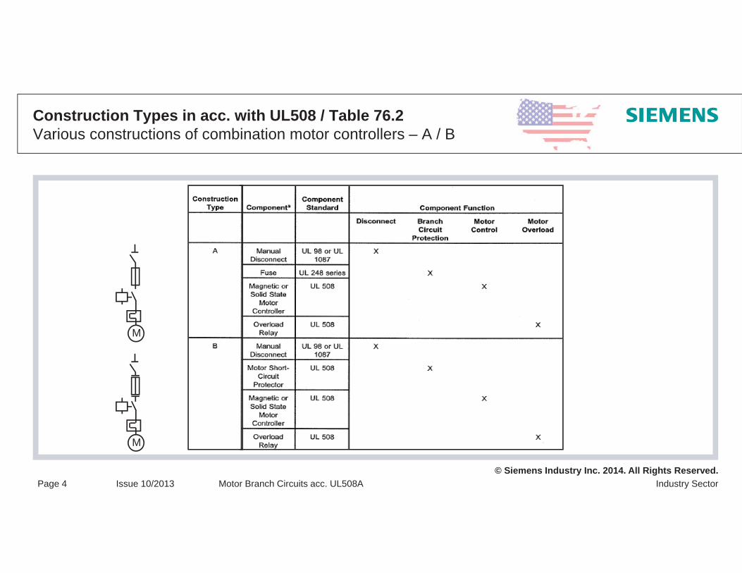
Construction Types in acc. with UL508 / Table 76.2 Various constructions of combination motor controllers – A / B
M
M

© Siemens Industry Inc. 2014. All Rights Reserved.Industry SectorPage 5 Issue 10/2013 Motor Branch Circuits acc. UL508A
Construction Types in acc. with UL508 / Table 76.2 Various constructions of combination motor controllers – C / D
x
M
x
M
© Siemens Industry Inc. 2014. All Rights Reserved.Industry SectorPage 6 Issue 10/2013 Motor Branch Circuits acc. UL508A
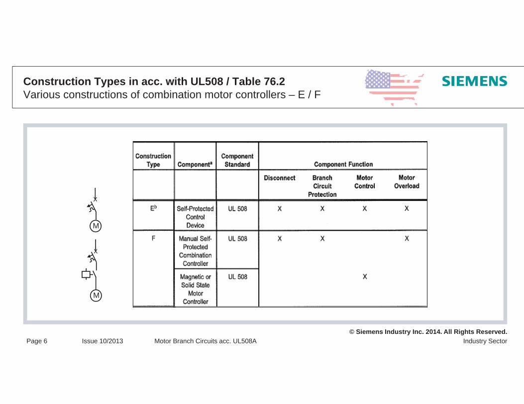
Construction Types in acc. with UL508 / Table 76.2 Various constructions of combination motor controllers – E / F
x
M
x
M
© Siemens Industry Inc. 2014. All Rights Reserved.Industry SectorPage 7 Issue 10/2013 Motor Branch Circuits acc. UL508A
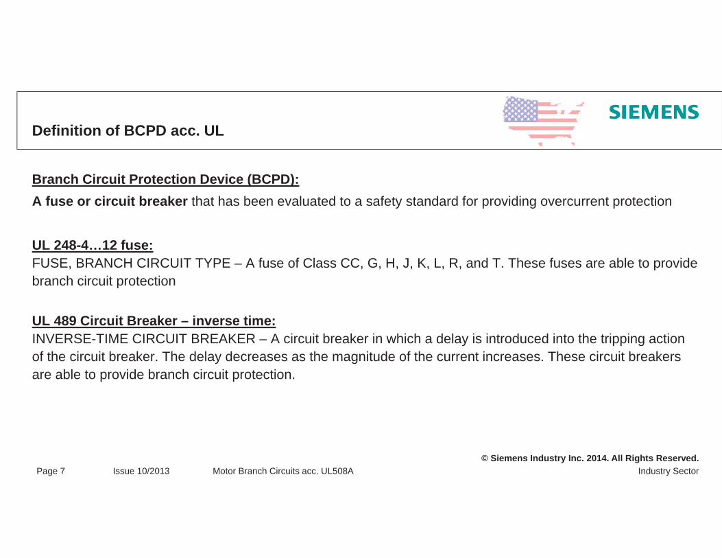
Definition of BCPD acc. UL
Branch Circuit Protection Device (BCPD):A fuse or circuit breaker that has been evaluated to a safety standard for providing overcurrent protection
UL 248-4…12 fuse:FUSE, BRANCH CIRCUIT TYPE – A fuse of Class CC, G, H, J, K, L, R, and T. These fuses are able to provide branch circuit protection
UL 489 Circuit Breaker – inverse time:INVERSE-TIME CIRCUIT BREAKER – A circuit breaker in which a delay is introduced into the tripping action of the circuit breaker. The delay decreases as the magnitude of the current increases. These circuit breakers are able to provide branch circuit protection.

© Siemens Industry Inc. 2014. All Rights Reserved.Industry SectorPage 8 Issue 10/2013 Motor Branch Circuits acc. UL508A
BCPD – Branch Circuit Protection Devices
Inverse time C.B. UL489 C.B. / CSA 22.2 No. 5-09
3RV27/28 3RV17/18 3VL
Class CC Fuses acc. UL248-4 / CSA 22.2 No. 248.4
3NW

© Siemens Industry Inc. 2014. All Rights Reserved.Industry SectorPage 9 Issue 10/2013 Motor Branch Circuits acc. UL508A
Motor Starters vs. Type E combination motor controller
Type E combination motor controlleracc. UL508 / CSA 22.2 No. 14
Approved as branch circuit protection devicefor motor loads only!
Slash voltage rating only!
Manual motor controller / motor starteracc. UL508 / CSA 22.2 No. 14
Approved as motor disconnect and motor overload protectioncan not be used as a branch circuit protection device!
Delta voltage rating!
3RV2
3RV23LD

© Siemens Industry Inc. 2014. All Rights Reserved.Industry SectorPage 10 Issue 10/2013 Motor Branch Circuits acc. UL508A
Definition of Motor Starters
There are two types of Motor Starters certified for use in USA and Canada…Motor Starters and Type E Combination Motor Controllers.Motor Starters do not offer any branch circuit protection.Type E Combination Motor Controllers offer branch circuit protection for motors.
Manual Motor Controller (Motor Starter):A device designed for manual-only control of a motor under normal and locked rotor conditions. A motor controller may incorporate a means to automatically interrupt motor overload currents. Some manual motor controllers are provided with limited short circuit interrupting capabilities; however, the certification report will state that the ability of these devices to open the short circuit currents was not evaluated. A manual motor controller is evaluated to CAN/CSA-C22.2 No. 14.
Type E Combination Motor Controller:A single device designed to control a motor under normal and locked rotor conditions, disconnect the motor branch circuit and interrupt short circuit and overload overcurrents having non-replaceable or integral discriminating overload andshort circuit sensors, and provided with one or more sets of contacts where the contacts cannot be isolated for separate testing. A Type E combination motor controller is evaluated to the requirements of CSA Standard C22.2 No. 14-95.

© Siemens Industry Inc. 2014. All Rights Reserved.Industry SectorPage 11 Issue 10/2013 Motor Branch Circuits acc. UL508A
Definition of Terms / Explanations – Service Factor SF
Note:
SF = 1.0 corresponds to a setting value of 0.92 FLA
SF 1.15 corresponds to a setting value of 1.0 FLA
Definition:
The service factor - SF - is a measure of periodically overload capacity at which a motor can operate without overload or damage.
The NEMA standard Service Factor for fully enclosed motors is SF 1.0
SF: service factor SF 1.0 / SF 1.15 to be used for the overload setting of an overload relais Important parameter for the setting of the Bi-metal relay. Only a Service Factors other than SF1.0 have to be indicated on the nameplate.SF1.0 is normally not indicated on the name plate. NEC 2011 – 430.32 (1)
© Siemens Industry Inc. 2014. All Rights Reserved.Industry SectorPage 12 Issue 10/2013 Motor Branch Circuits acc. UL508A
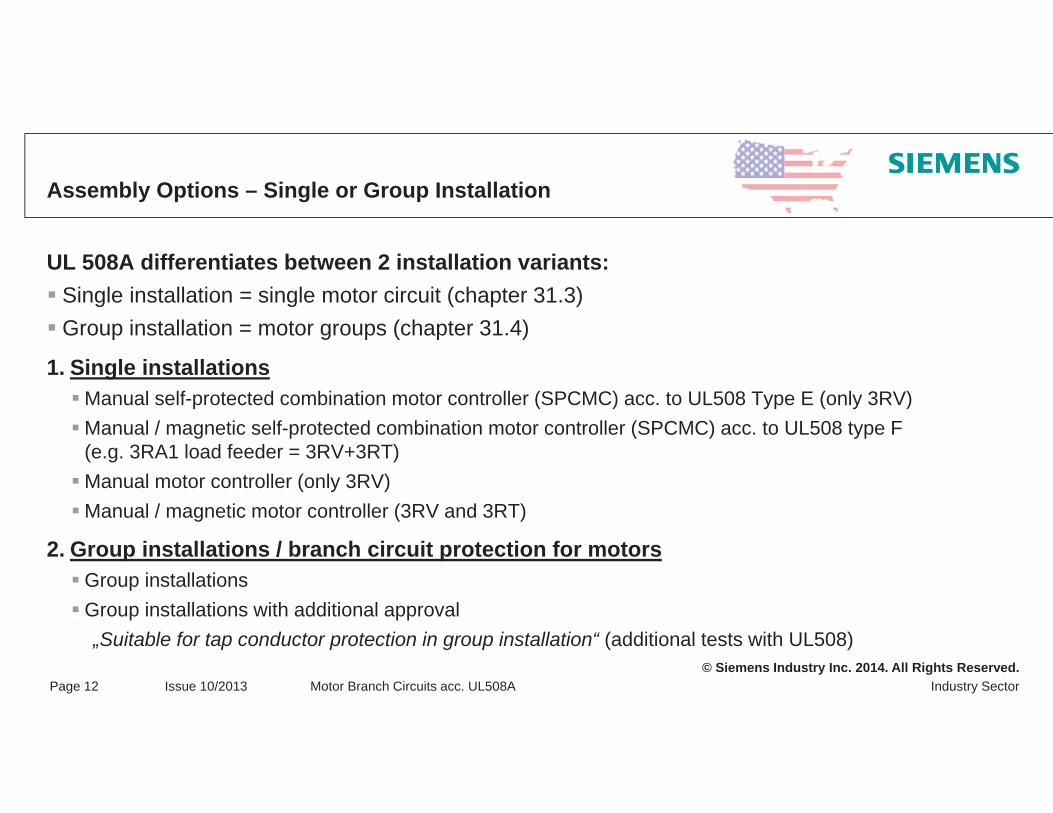
Assembly Options – Single or Group Installation
UL 508A differentiates between 2 installation variants:Single installation = single motor circuit (chapter 31.3)Group installation = motor groups (chapter 31.4)
1. Single installationsManual self-protected combination motor controller (SPCMC) acc. to UL508 Type E (only 3RV) Manual / magnetic self-protected combination motor controller (SPCMC) acc. to UL508 type F (e.g. 3RA1 load feeder = 3RV+3RT) Manual motor controller (only 3RV)Manual / magnetic motor controller (3RV and 3RT)
2. Group installations / branch circuit protection for motorsGroup installationsGroup installations with additional approval „Suitable for tap conductor protection in group installation“ (additional tests with UL508)
© Siemens Industry Inc. 2014. All Rights Reserved.Industry SectorPage 13 Issue 10/2013 Motor Branch Circuits acc. UL508A
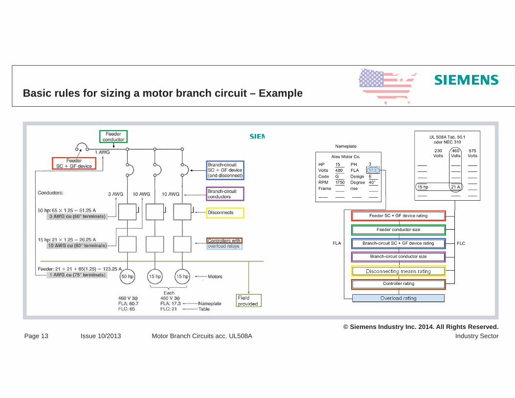
Basic rules for sizing a motor branch circuit – Example
© Siemens Industry Inc. 2014. All Rights Reserved.Industry SectorPage 14 Issue 10/2013 Motor Branch Circuits acc. UL508A
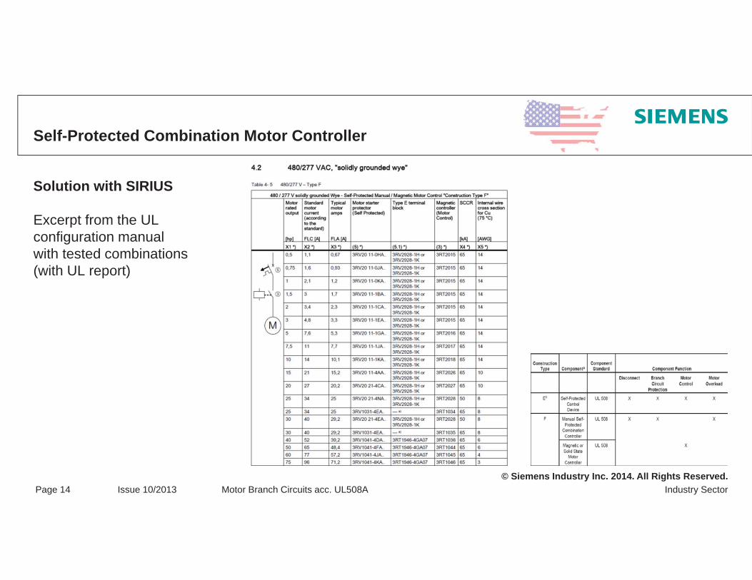
Self-Protected Combination Motor Controller
Solution with SIRIUS
Excerpt from the UL configuration manual with tested combinations (with UL report)
© Siemens Industry Inc. 2014. All Rights Reserved.Industry SectorPage 15 Issue 10/2013 Motor Branch Circuits acc. UL508A
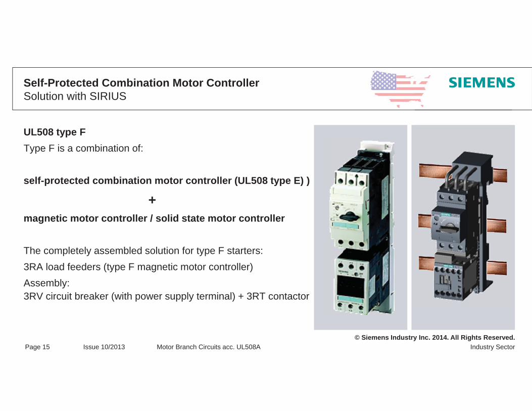
Self-Protected Combination Motor Controller Solution with SIRIUS
UL508 type FType F is a combination of:
self-protected combination motor controller (UL508 type E) )
+magnetic motor controller / solid state motor controller
The completely assembled solution for type F starters: 3RA load feeders (type F magnetic motor controller)Assembly:3RV circuit breaker (with power supply terminal) + 3RT contactor
© Siemens Industry Inc. 2014. All Rights Reserved.Industry SectorPage 16 Issue 10/2013 Motor Branch Circuits acc. UL508A
Assembly OptionsSingle Installation
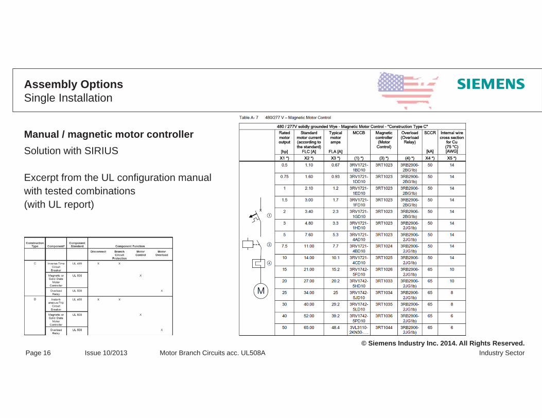
Manual / magnetic motor controller Solution with SIRIUS
Excerpt from the UL configuration manualwith tested combinations(with UL report)

© Siemens Industry Inc. 2014. All Rights Reserved.Industry SectorPage 17 Issue 10/2013 Motor Branch Circuits acc. UL508A
What is the definition of a Group Installation
Definition of a Group Installation:A group of loads, consisting of two or more motors, or one or more motors and other loads,
are able to be protected by a single set of branch circuit fuses or inverse – time circuit breaker
as specified in Method A, B or C(see the following slides for details)
BCPD
Starter Starter Contactor
Motor Motor Heater

© Siemens Industry Inc. 2014. All Rights Reserved.Industry SectorPage 18 Issue 10/2013 Motor Branch Circuits acc. UL508A
Sizing of Branch Circuit Protection for Motor Groups acc. UL/NECMethod A – General requirements
Branch circuit protection not >20A @125V max., or not > 15A @600VEach motor not >6A FLA, Branch Circuit Protection not greater than any component restrictions, andCoordinated with requirements for any non-motor loads per 31.4.4
31.4.4 For a group that includes other (non-motor) loads, additional branch circuit fuses or inverse time circuit breakers shall be provided in each circuit
Exception: Where the ampere rating of the branch circuit protection determined in 31.4.1 does notexceed the applicable branch circuit protection requirements in 31.5 – 31.8 for a non-motor load in the group, additional branch circuit protection is not required
© Siemens Industry Inc. 2014. All Rights Reserved.Industry SectorPage 19 Issue 10/2013 Motor Branch Circuits acc. UL508A
Sizing of Branch Circuit Protection for Motor Groups acc. UL/NECMethod A – Assembly
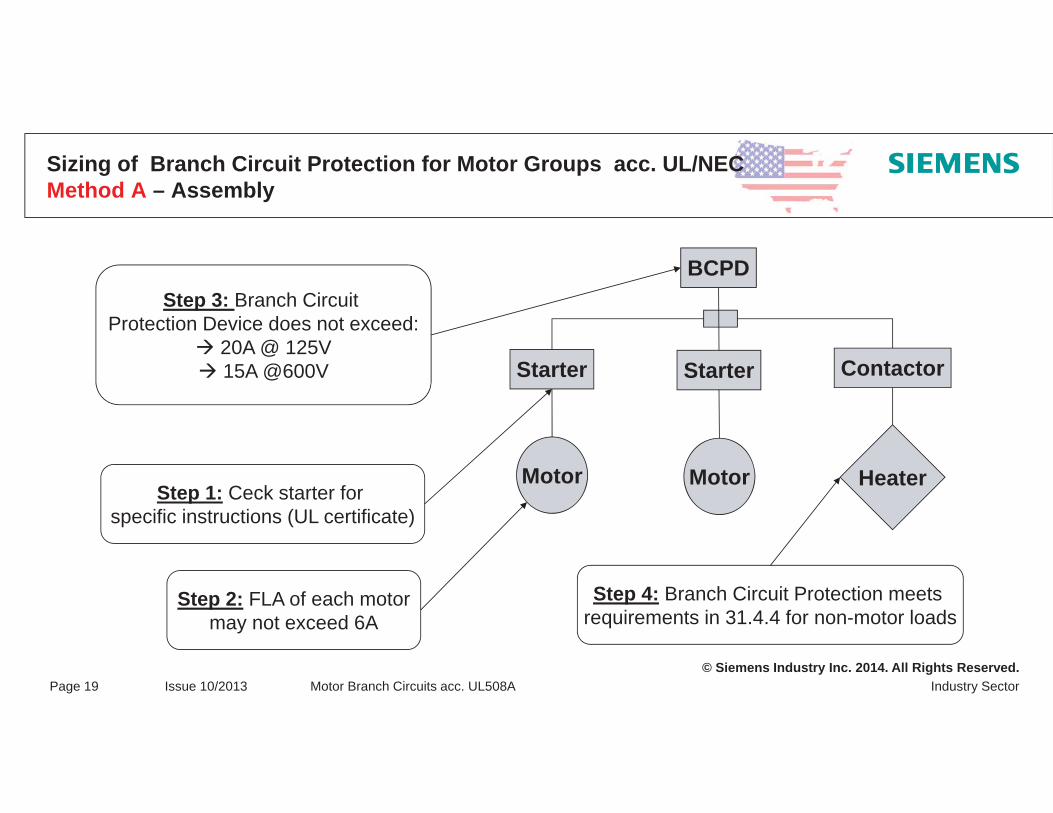
BCPD
Starter Starter Contactor
Motor Motor Heater
Step 3: Branch Circuit Protection Device does not exceed:
20A @ 125V15A @600V
Step 1: Ceck starter for specific instructions (UL certificate)
Step 2: FLA of each motormay not exceed 6A
Step 4: Branch Circuit Protection meets requirements in 31.4.4 for non-motor loads

© Siemens Industry Inc. 2014. All Rights Reserved.Industry SectorPage 20 Issue 10/2013 Motor Branch Circuits acc. UL508A
Sizing of Branch Circuit Protection for Motor Groups acc. UL/NECMethod B – General requirements
BCPD size complies with single motor requirements for each individual motor
Tap conductors not less than 1/3 the ampacity of branch circuit conductor, or not less than 1/10 the amp rating of branch circuit protection if Manual Motor Controller marked “Suitable as Tap Conductor Protection in Group Installations”
Additional branch circuit protection for non-motor loads unless branch circuit protection device also meets 31.5 through 31.8 for non-motor loads in group
C.B. inverse time:400 percent of full-load motor current for an inverse-time circuit breaker not exceeding 100 amperes300 percent of full-load motor current for an inverse-time circuit breaker rated more than 100 amperes;
Fuses:225 percent of full-load motor current for a time delay (dual element) fuse400 percent of full-load motor current for a non-time delay fuse or a Class CC time delay fuse not exceeding 600 amperes;

© Siemens Industry Inc. 2014. All Rights Reserved.Industry SectorPage 21 Issue 10/2013 Motor Branch Circuits acc. UL508A
Sizing of Branch Circuit Protection for Motor Groups acc. UL/NECMethod B – Assembly
BCPD
Starter Starter Contactor
Motor Motor Heater
Step 1: Select Branch Circuit Protection Device not to exceed
single motor sizing for smallest motor
Step 2: Ampacity of tap conductors not less than 1/3 ampacity, or
1/10 rating of BCPD when manual motor controller is marked as “Suitablefor tap conductor protection in group
installations
Step 3: Check if non-motor loads require additional protection

© Siemens Industry Inc. 2014. All Rights Reserved.Industry SectorPage 22 Issue 10/2013 Motor Branch Circuits acc. UL508A
Sizing of Branch Circuit Protection for Motor Groups acc. UL/NECMethod C – General requirements
All controllers marked for group installation with BCPD sized at the lesser of:- the smallest group installation marking for BCPD, or- the calculated BCPD for the largest motor + FLAS’s of other loads
Tap conductors sized per Method B
Non-Motor loads also protected per Method B
Applies to power conversion equipment with DC converter and inverter sections on “common bus”
© Siemens Industry Inc. 2014. All Rights Reserved.Industry SectorPage 23 Issue 10/2013 Motor Branch Circuits acc. UL508A
Sizing of Branch Circuit Protection for Motor Groups acc. UL/NECMethod C – Assembly
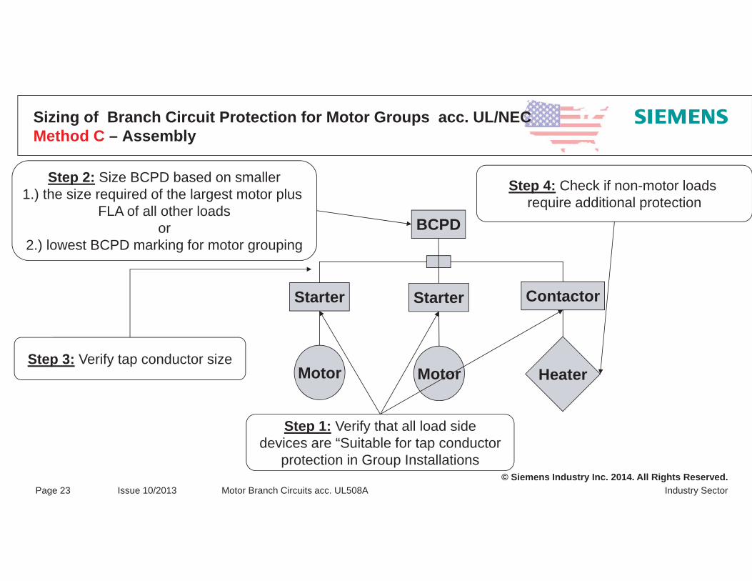
BCPD
Starter Starter Contactor
Motor Motor Heater
Step 2: Size BCPD based on smaller1.) the size required of the largest motor plus
FLA of all other loadsor
2.) lowest BCPD marking for motor grouping
Step 3: Verify tap conductor size
Step 1: Verify that all load sidedevices are “Suitable for tap conductor
protection in Group Installations
Step 4: Check if non-motor loads require additional protection

© Siemens Industry Inc. 2014. All Rights Reserved.Industry SectorPage 24 Issue 10/2013 Motor Branch Circuits acc. UL508A
How to size the Branch Circuit Protection Device for Motor Groups acc UL/NEC?
BCPD
Starter Starter Contactor
Motor Motor Heater
Verify if non-motor loads require
additional protection
11 Amps 5 Amps 5 Amps
Example for UL Circuit Breaker:1.) 11 Amps x 250% = 27,5 Amps2.) 27,5A + 5A + 5A = 37,5 Amps
37,5 Amps for the BCPDNext Standard size is 40 Amps
Tap Conductors:125% of the largest motor load + 100% of additional loads = 23,75 Amps
23,75 / 3 = 7.9 AmpsUL508A Table 28.1 for ampacities of conductors:
minimum 14 AWG for Power Circuits

© Siemens Industry Inc. 2014. All Rights Reserved.Industry SectorPage 25 Issue 10/2013 Motor Branch Circuits acc. UL508A
Example with the 3RM1 motor starter
16A max per infeed
X
Y
Ampacity Y 1/3 Amapacity X

© Siemens Industry Inc. 2014. All Rights Reserved.Industry SectorPage 26 Issue 10/2013 Motor Branch Circuits acc. UL508A
Explanations, Notes, Rating Plate Data Motor branch circuit – nameplate of 3RV circuit breakers
Indication of hp ratings for 200-208 V, 230 V, 460 V, 575 V
General safety instructions
Only CU wires for 75°C are allowed
Ratio of 125% of tripping current : setting current
Breaks all phases simultaneously
Max. permissiblemotor‘s full load amps(FLA max.)
Reference to the use in combinations with contactors and soft starters
Manual motor controller, suitable as tap conductor protection, in group installationsmotor disconnect suitable for group installationmax. permissible grouping fuse / CBmax. permissible short circuit current
Self-protected combination motor controller (E / F)with reference to adaptermax. permissible short circuits for 240 V, 480Y/277 V, 600Y/347 V
Example: 3RV10 21

© Siemens Industry Inc. 2014. All Rights Reserved.Industry SectorPage 27 Issue 10/2013 Motor Branch Circuits acc. UL508A
Note: … … are placeholders to be supplemented with the technical data of the product (size-related).
Explanations, Notes, Rating Plate DataMotor branch circuit – rating plate of 3RT contactors
Example: 3RT10 2
Contactor
General purpose values (non-motor operated loads)
Permissible short circuit at 600 V AC, value 5 kA derived from UL508,higher values from report
Indication of hp ratings for motors, at 115 V, 230 V, 460 V, 575 V
Screwdriver specification: Pozidrive 2
Only Cu lines for 75°C are allowed
Breaks all phases simultaneously
Maximum permissible RK5 fuse, maximum permissible circuit breaker
Wire stripping length, permissible wire cross sections in AWG
Permissible torque in pound per inch and Nm

© Siemens Industry Inc. 2014. All Rights Reserved.Industry SectorPage 28 Issue 10/2013 Motor Branch Circuits acc. UL508A
Example: 3RU11 2
Explanations, Notes, Nameplate DataMotor branch circuit – nameplate of overload relays
Maximum permissible RK5 fuse, maximum permissible circuit breaker
Certified for 600 V AC (max.)
Only Cu lines for 75°C are allowed
Note: … … are placeholders to be supplemented with the technical data of the product (size-related).
Ratio of tripping current : setting current = 125%
Safety note for AUTO RESET
Permissible short circuit at 600 V AC,value 5 kA derived from UL508,higher values from report
Permissible torque in pounds per inch and Nm

© Siemens Industry Inc. 2014. All Rights Reserved.Industry SectorPage 29 Issue 10/2013 Motor Branch Circuits acc. UL508A
Changes in the standard for industrial control devices
This change is not addressed to the user of industrial control devices but to the manufacturer of control devices!
Complete transition till Nov. 2017
UL 60947-4-1 is aligned and harmonized
with theIEC 60947-4-1

© Siemens Industry Inc. 2014. All Rights Reserved.Industry SectorPage 30 Issue 10/2013 Motor Branch Circuits acc. UL508A
What does the transition from UL508 to UL60947-4-1 affect?
Type of co-ordination 1 Type of co-ordination 2

© Siemens Industry Inc. 2014. All Rights Reserved.Industry SectorPage 31 Issue 10/2013 Motor Branch Circuits acc. UL508A
Panel MarkingAccording UL508A – § SB5

© Siemens Industry Inc. 2014. All Rights Reserved.Industry SectorPage 32 Issue 10/2013 Motor Branch Circuits acc. UL508A
Predictable Reaction Type of co-ordination “1”
UL 60947-4-1 (excerpt):With type of co-ordination “1”, the contactor or starter must not endanger persons or the installation in the event of a short circuit and need not be suitable for further operation without repair and renewal of parts.
Result for the machine or machine operation:The contactor and/or overload relay might be defectiveThe components might be unsuitable for further operationInsecure personnel and system protection with further operationUncertain functionality of the componentsThe components should be replaced
Consequences: Long downtimesHigh repair efforts

© Siemens Industry Inc. 2014. All Rights Reserved.Industry SectorPage 33 Issue 10/2013 Motor Branch Circuits acc. UL508A
Predictable Reaction Type of Co-Ordination “2”
UL 60947-4-1 (excerpt):With type of co-ordination “2”, the contactor or starter must not endanger persons or the installation inthe event of a short circuit and must remain suitable for further operation. The risk of contact welding is given. In this case, maintenance instructions have to be provided by the manufacturer.
Note: If manufacturer recommendations are not complied with for the application of an SCPD, the type of co-ordination is questionable. The risk of contact welding is given.Manufacturer’s maintenance instruction for opening the contact pieces is required
Result for the machine or machine operationThe contactor and/or overload relay may be slightly welded Easy breaking-open of contacts required in case of welding
Consequences:Short downtimesLow repair effort

© Siemens Industry Inc. 2014. All Rights Reserved.Industry SectorPage 34 Issue 10/2013 Motor Branch Circuits acc. UL508A
Where can I get these values?
Ask your supplier for SCCR ratings for Type 1 and Type 2 co-ordination
© Siemens Industry Inc. 2014. All Rights Reserved.Industry SectorPage 35 Issue 10/2013 Motor Branch Circuits acc. UL508A
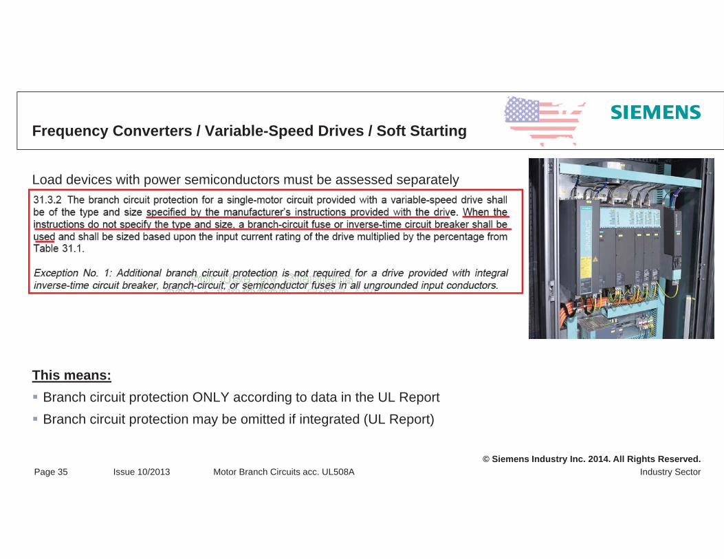
Frequency Converters / Variable-Speed Drives / Soft Starting
Load devices with power semiconductors must be assessed separately
This means:Branch circuit protection ONLY according to data in the UL Report Branch circuit protection may be omitted if integrated (UL Report)

© Siemens Industry Inc. 2014. All Rights Reserved.Industry SectorPage 36 Issue 10/2013 Motor Branch Circuits acc. UL508A
SCCR ratings for Siemens VFD’s
All the specified drives have a high SCCR as a result of testing with UL.All drives have internal solid state short circuit protection for protection of the drive output but this has not been evaluated for branch circuit protection (BCP)
Our UL certification allows all drives (which have an integral solid state protection circuit) to adopt a high SCCR equal to the interrupt current rating of the branch-circuit protective device protecting the drive.
Example. If a UL listed combination motor protector (Rated current 40A) with an interrupt current rating of 65kA is used as the branch circuit protection device for a MICROMASTER 440 frame size C 400V 11kW drive, the high SCCR of the drive is equal to that of the combination motor protector, which is 65kA.
Hence by selection of the correct UL listed BCP device, with appropriate interrupt rating for the application, any high SCCR rating can be achieved for the above drives.
Short Circuit Current Ratings (SCCR) for Siemens Standard Drives
© Siemens Industry Inc. 2014. All Rights Reserved.Industry SectorPage 37 Issue 10/2013 Motor Branch Circuits acc. UL508A
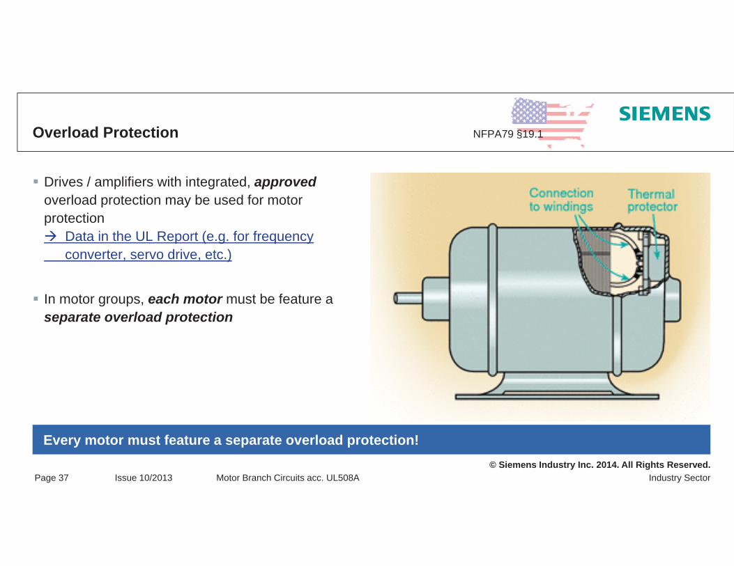
Overload Protection NFPA79 §19.1
Drives / amplifiers with integrated, approvedoverload protection may be used for motor protection
Data in the UL Report (e.g. for frequency converter, servo drive, etc.)
In motor groups, each motor must be feature a separate overload protection
Every motor must feature a separate overload protection!

© Siemens Industry Inc. 2014. All Rights Reserved.Industry SectorPage 38 Issue 10/2013 Motor Branch Circuits acc. UL508A
Example – Excerpt from SINAMIC G120/130/150 – UL Report
3NE1
Note:
A semiconductor fuse according to UL248-13 does NOT representa suitable branch circuit protective device (unless specified in the UL Report)
A semiconductor fuse can be ADDITIONALLY installed at any time
3NE1 813 SIEMENS SITOR Fuse
Semiconductor LV HRC design
UL recognized only!

© Siemens Industry Inc. 2014. All Rights Reserved.6_Motor branch circuits acc. to UL508A_en.ppt
Thank you for your attention!Questions?

© Siemens Industry Inc. 2014. All Rights Reserved.
Protection Against Electric Shock
Protection against direct contact
Protection against electric shock in case of indirect contact (fault case)
© Siemens Industry Inc. 2014. All Rights Reserved.Industry SectorPage 2 Issue date 07/2013 Industrial Control Panels and Machinery for North America
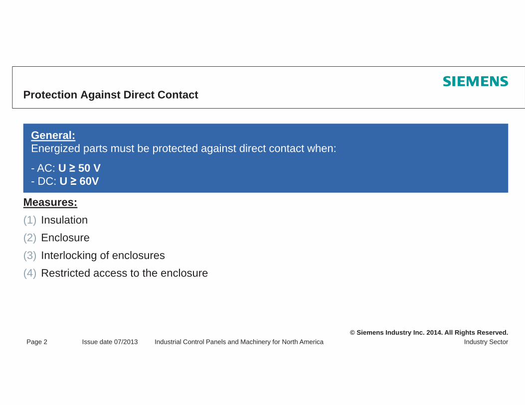
Protection Against Direct Contact
Measures:(1) Insulation(2) Enclosure(3) Interlocking of enclosures(4) Restricted access to the enclosure
General:Energized parts must be protected against direct contact when:
- AC: U 50 V- DC: U 60V

© Siemens Industry Inc. 2014. All Rights Reserved.Industry SectorPage 3 Issue date 07/2013 Industrial Control Panels and Machinery for North America
Protection Against Direct Contact(1) Insulation
Energized parts must meet the following conditions:
Complete insulation (only removable through disassembly!)
Mechanical, chemical, electrical and thermal resistance
Paints, varnishes and coatings do not offer sufficient protection against electric shock

© Siemens Industry Inc. 2014. All Rights Reserved.Industry SectorPage 4 Issue date 07/2013 Industrial Control Panels and Machinery for North America
Protection Against Direct Contact(2) Enclosures
Enclosures and enclosure openings must comply with the requirements according to:
UL508 UL508AUL50 or NEMA 250.
Exception:Unapproved enclosures can be checked by means of a test finger; checking of all openings after disassembly of all parts removable without tools
Touching of energized parts with the test finger must not be possible

© Siemens Industry Inc. 2014. All Rights Reserved.Industry SectorPage 5 Issue date 07/2013 Industrial Control Panels and Machinery for North America
Test Finger – NFPA79 6.2.2.1

© Siemens Industry Inc. 2014. All Rights Reserved.Industry SectorPage 6 Issue date 07/2013 Industrial Control Panels and Machinery for North America
Protection Against Direct Contact(3) Interlocking of Enclosures
Exceptions:1. Main disconnecting means for industrial control panel lighting inside the industrial control panel 2. Main disconnecting means for memory elements for the retention of information
General: Main disconnecting means of enclosures / industrial control panels must be interlocked with the door when energized parts are contained with - AC 50 V- DC 60 V
Note:Qualified persons may implement measures for defeating the interlocking (see NFPA 70E "Standard for Electrical Safety in Workplaces")

© Siemens Industry Inc. 2014. All Rights Reserved.Industry SectorPage 7 Issue date 07/2013 Industrial Control Panels and Machinery for North America
Protection Against Direct Contact(3) Interlocking of Enclosures – Conditions
The interlocking must be defeatable by means of a tool With the door open and the "ON" position, the interlocking must be enabled upon closingWith the door is open, switch-on must be mechanically blocked; defeat must be possible without tools ("deliberate action")
Caution: Devices on the inside of industrial control panels must be protected against unintended contact when U 50 V; either by means of devicecharacteristics or through barriersin a range of 50 mm (2 inches)

© Siemens Industry Inc. 2014. All Rights Reserved.Industry SectorPage 8 Issue date 07/2013 Industrial Control Panels and Machinery for North America
Protection Against Direct Contact (3) Interlocking of Enclosures – Solutions
Mechanical solutions:UL-compliant with UL508A, NFPA 79, JIC and NEC
Max-flex driveEnclosure type: 1, 3R, 12
Interlocking module 8UCEnclosure type: 1
Standard references:UL508A: 30.4 / 66.1.5 / 66.6.3NFPA79: 5.3.3 / 6.2.3 / 6.2.5
UL Guideline, Chapter 6.1.4

© Siemens Industry Inc. 2014. All Rights Reserved.Industry SectorPage 9 Issue date 07/2013 Industrial Control Panels and Machinery for North America
Protection Against Direct Contact(3) Interlocking of Enclosures – mechanical solutions
Examples for mechanical interlocking solutions provided by Siemens

© Siemens Industry Inc. 2014. All Rights Reserved.Industry SectorPage 10 Issue date 07/2013 Industrial Control Panels and Machinery for North America
Protection Against Direct Contact(3) Interlocking of Enclosures – Solutions
Electrical solutions:1 key switch for defeat1 timing relay1 undervoltage release per main disconnecting meansDiverse auxiliary relays1 limit switch per door, preferably with tumblerMotorized operating mechanism
Note:The electrical interlocking must meet the same conditions as the mechanical interlocking!
UL Guideline, Chapter 6.1.4
© Siemens Industry Inc. 2014. All Rights Reserved.Industry SectorPage 11 Issue date 07/2013 Industrial Control Panels and Machinery for North America
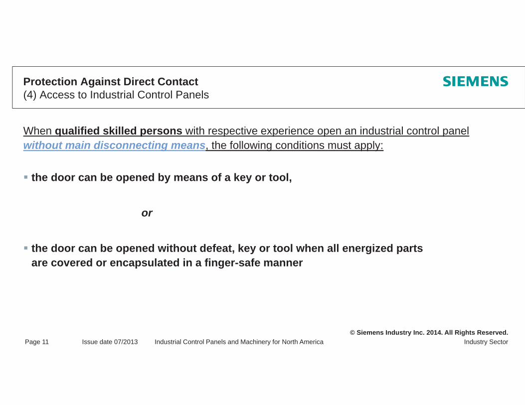
Protection Against Direct Contact(4) Access to Industrial Control Panels
When qualified skilled persons with respective experience open an industrial control panel without main disconnecting means, the following conditions must apply:
the door can be opened by means of a key or tool,
or
the door can be opened without defeat, key or tool when all energized parts are covered or encapsulated in a finger-safe manner

© Siemens Industry Inc. 2014. All Rights Reserved.Industry SectorPage 12 Issue date 07/2013 Industrial Control Panels and Machinery for North America
Protection Against Indirect Contact (Fault Case) NFPA79 §6.3
General:
Protection against indirect contact is to prevent hazardous states in case of faults(e.g. due to insulation faults between energized and exposed parts)
Measures: (1) Protection through double insulation(2) Protection through automatic supply disconnection
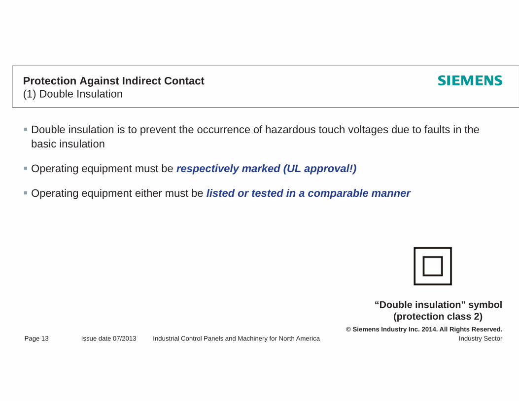
© Siemens Industry Inc. 2014. All Rights Reserved.Industry SectorPage 13 Issue date 07/2013 Industrial Control Panels and Machinery for North America
Protection Against Indirect Contact(1) Double Insulation
“Double insulation" symbol(protection class 2)
Double insulation is to prevent the occurrence of hazardous touch voltages due to faults in the basic insulation
Operating equipment must be respectively marked (UL approval!)
Operating equipment either must be listed or tested in a comparable manner

© Siemens Industry Inc. 2014. All Rights Reserved.Industry SectorPage 14 Issue date 07/2013 Industrial Control Panels and Machinery for North America
Protection Against Indirect Contact(2) Protection Through Automatic Supply Disconnection
Prerequisites for the safety measure:1. Exposed, conductive parts must be grounded
2. Application of overcurrent protective devices for automatic disconnection
General:
Protection through automatic supply disconnection of affected circuits by means of the respective overcurrent protective device in case of faults

© Siemens Industry Inc. 2014. All Rights Reserved.
Thank you for your attention!Questions?