sierra bonita: innovative use of long span metal deck slabs and shored · pdf...
TRANSCRIPT

Sierra Bonita: Innovative Use of Long Span Metal Deck Slabs and Shored
Construction
Joseph Mugford P.E.1, Karl Rubenacker S.E.
1, John Lantry P.E.
1, Ramon
Gilsanz S.E.1
1Gilsanz.Murray.Steficek.LLP, 129 West 27
th Street, 5
th Floor New York, NY 10001;
PH 212-254-0030; FAX 212-477-5978; email: [email protected]
INTRODUCTION
Sierra Bonita is a mixed use building providing affordable housing for people
living with disabilities. The five story building is located in West Hollywood, CA
and was completed in 2010. A 6 inch reinforced metal deck slab system spans 20 feet
between supporting steel framing. The supporting framing consists of 43 foot long
beams and 60 foot long girders supported by columns at the building perimeter and at
the four corners of the central building atrium.
Occupant induced floor vibrations as well as service and creep deflections
were taken into account in the design process. Finite element modeling using
SAP2000 was used to predict the response of the structure from walking induced
vibrations. Testing was later performed during construction in conjunction with The
Pennsylvania State University to confirm the acceptability of the structural response.
Service and creep deflections were mitigated using slab reinforcement, camber, wood
joist shores and loose steel shores. This paper presents our approach to the design of
this system, including modeling techniques; use of construction sequencing and
shoring; and a comparison of in service vs. design results.
STRUCTURAL SYSTEM SELECTION
In pursuit of the project goals, a structural system with a shallow floor depth
and a minimal wall thickness or column size would be required. The system would
also need to accommodate the retail and parking occupancies on the lower level. In
residential buildings, these goals are typically achieved with a concrete flat plate. A
flat plate system, however, would likely have required a transfer level at the second
floor and the additional weight would also increase the seismic base shear of the
building and thus the cost.
In California, low rise residential buildings typically consist of wood framing
supported by bearing walls. While this system provides a fairly shallow floor depth
at low cost and weight, it would also require a transfer podium structure to
accommodate the lower level occupancy. A hybrid steel frame/wood joist solution
combined the benefits of the wood bearing wall system with the flexibility of a steel
system. This system, however, provided a modest 7’-8” ceiling height and would not
have ideal fire performance characteristics.
1st Residential Building Design & Construction Conference – February 20-21, 2013 at Sands Casino Resort, Bethlehem, PA PHRC.psu.edu
358

Figure 1
Typical Residential Floor Layout
An ideal solution, combing the flexibility and light weight of steel framing
with the shallow floor depth of a concrete flat plate was decided upon. Steel beams
were located in line with the demising partitions between adjacent apartments. The
beams span between the building perimeter and the girders around the central atrium.
Four corner columns define the central atrium space resulting in a structural system
with 20 foot slab spans, 43 foot beam spans and 60 foot girder spans. This system
required particularly special attention to deflection and vibration performance.
1st Residential Building Design & Construction Conference – February 20-21, 2013 at Sands Casino Resort, Bethlehem, PA PHRC.psu.edu
359

Figure 2
Typical Residential Floor Structural Framing Plan
LONG SPAN SLABS
As a result of the apartment layout, the typical one way slab span of the
structure is 20 feet. This is beyond the limits in use for conventional metal deck slabs
and required a different design approach. Following ACI 318 guidelines would have
required a maximum slab thickness of 10”. In previous projects it was found that the
performance of reinforced metal deck slabs outperformed this empirical guide line.
Performance of metal deck slabs were found to be satisfactory up to a span to depth
ratio of L/43. Building on this experience, we selected a span ratio of L/40 for the
Sierra Bonita Project.
1st Residential Building Design & Construction Conference – February 20-21, 2013 at Sands Casino Resort, Bethlehem, PA PHRC.psu.edu
360

Figure 3
Comparison of Steel/Wood Hybrid System vs. Long Span Slab System
To determine the deflection characteristics of the slab, two methods were
used. Initial hand calculations were performed using the effective moment of inertia
method in ACI 318. Long term creep deflections were accounted for with a standard
multiplier of 2 on the long term dead load. Modulus of rupture of the concrete was
assumed to be 7.5√(f’c) . Using this method, long term dead load deflection plus live
load deflection was found to be L/339 and total deflection including long term dead
load deflection was found to be L/226. Although these results exceed the
recommended deflection limitation of L/360 and L/240, the findings were preliminary
and were used for input into a more accurate finite element model that would include
the contribution of the framing members and steel reinforcement.
Following the completion of the hand calculations, a SAFE finite element
model was constructed that would accurately capture the stiffness contribution of the
other structural elements. Several iterations were performed, adjusting the top and
bottom steel and concrete strength until the predicted total deflections were within the
long term live and total load deflection limits of L/360 and L/240 respectively. The
contribution of the metal deck was modeled as an equivalent layer of reinforcing steel
at the mid depth of the metal deck.
Once deflections were found to be in accordance with the above limitations
the slab reinforcing was checked for strength. Using 6000psi concrete, the 1 ½” 20
gauge metal deck was found to have sufficient strength to function as the bottom
reinforcement of the slab. A nominal amount of top reinforcing consisting of
#5@12” was required for the negative moment over the beams. End spans required
additional reinforcing of #6@6”. Because UL fire tests only cover metal deck spans
up to 17 feet, bottom reinforcement was added to supplement the metal deck.
1st Residential Building Design & Construction Conference – February 20-21, 2013 at Sands Casino Resort, Bethlehem, PA PHRC.psu.edu
361

SHORING AND ADDITIONAL DEFLECTION CONSIDERATIONS
Typically, concrete flat plate construction requires significant amounts of
form work and shoring. Additional time and man power is also required to strip form
work and re-shore the slabs as work progresses up the building. In lieu of continuous
vertical shoring, a method of “self-shoring” and loose shores provided a procedure
that would minimize the deflection of the slab under the wet weight of concrete,
increase the levelness of the slab pour and maintain a constant thickness of concrete
in the slab. By eliminating the majority of posts and/or screw jacks, work men were
able to proceed with further trades on the floor immediately below a concrete pour.
Shoring of the slab consisted of two layers of wood framing spanning between
the bottom flanges of the beams. Shims of varying thickness were installed between
the top layer of framing and the metal deck to provide a slight slab camber. The
bottom layer of framing consisted of off the shelf LVL lumber. Loose Shores at
beams and girders were also used in combination with camber to control the
deflection of the framing. The gap between the shore and the framing member was
set equivalent to the non-composite deflection from the weight of the wet concrete.
This allowed the contractor to achieve a level floor with minimal post-composite dead
load deflections.
Figure 4: Self Shoring System In Place
VIBRATION DESIGN AND FIELD RESULTS
Due to the long span of the beams, girders and slabs, vibration response of the
structure was an important consideration. To determine the vibration response of the
structure two methods were used. The first method follows the recommendations in
1st Residential Building Design & Construction Conference – February 20-21, 2013 at Sands Casino Resort, Bethlehem, PA PHRC.psu.edu
362
AISC Design Guide 11 Chapter 4 and the second method estimates the vibration
response using a finite element model.
Design Guide 11 estimates the natural frequency and peak acceleration of the
floor system by combining a weighted average response of the different “panel”
modes of a structure. Typically, the participating panels used in this analysis are
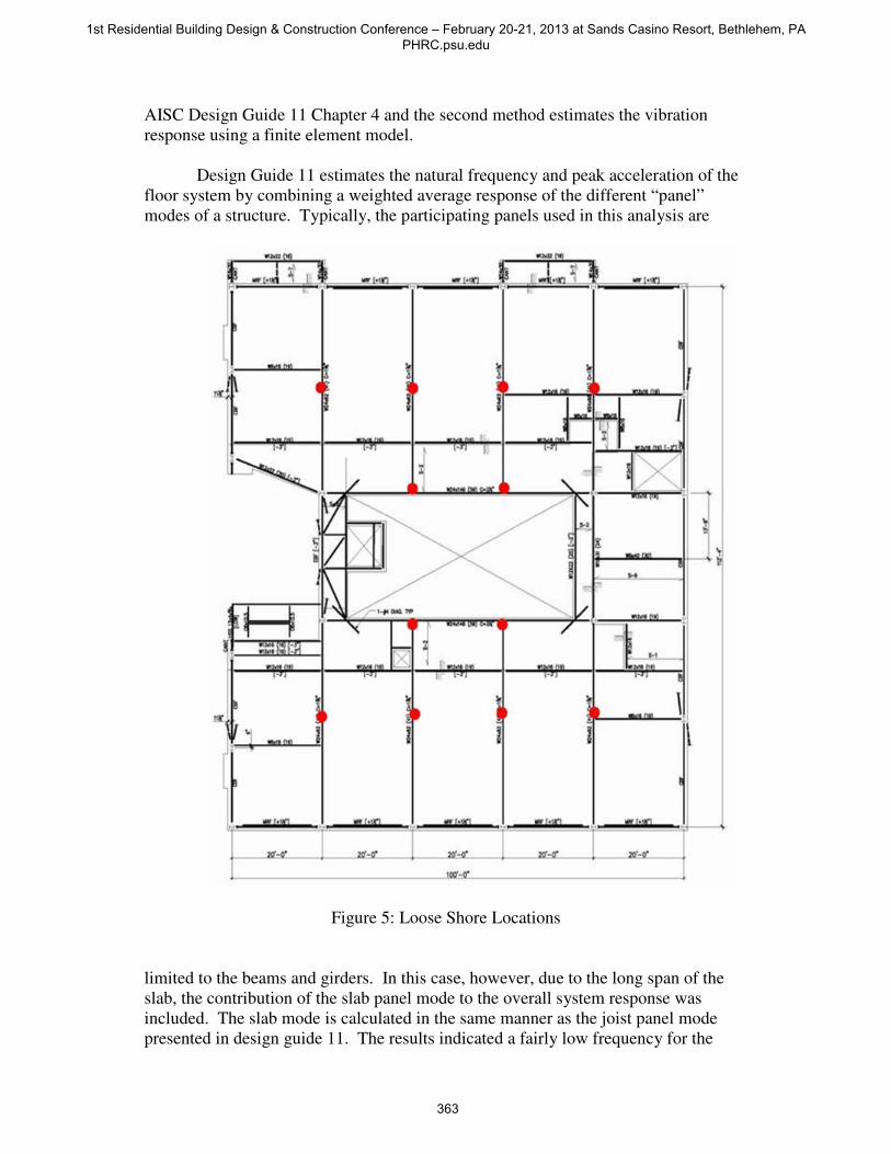
Figure 5: Loose Shore Locations
limited to the beams and girders. In this case, however, due to the long span of the
slab, the contribution of the slab panel mode to the overall system response was
included. The slab mode is calculated in the same manner as the joist panel mode
presented in design guide 11. The results indicated a fairly low frequency for the
1st Residential Building Design & Construction Conference – February 20-21, 2013 at Sands Casino Resort, Bethlehem, PA PHRC.psu.edu
363

typical floor at approximately 2.5Hz. A low frequency response was anticipated due
to the long spans of the structural system. The acceleration response was within the
maximum recommended acceleration limit of 0.5%g for residential occupancy. It
was 0.43%g.
Finite element modeling using SAP was also conducted to verify the results
derived from DG 11 hand calculations. The typical floor plate of the entire building
with columns was modeled in SAP. Slab stiffness parameters were modified to
reflect the stiffness contributions of the steel reinforcing and cracked concrete. To
determine the floor vibration response, a forcing function for a single 160 pound
person was used. A forcing function with 15 foot fall pulses was used to approximate
the input of a person walking across the length of the apartment. For simplicity, the
input force was located in the middle of the typical apartment in the middle of the
framing bay. This would be the most flexible area of the floor plate. A time history
analysis was conducted on all force inputs and the acceleration response spectrums
were plotted. The resulting peak acceleration of the time history analysis was 0.34%g
with 5% damping. This was deemed to be an acceptable level of vibration response
and was within the ISO curve in Design Guide 11. Additional areas were analyzed in
a similar manner to confirm these results.
Figure 6
SAP Finite Element Model
During construction, in conjunction with The Pennsylvania State University,
we visited the site to conduct vibration testing of the in place floor system. Testing
was conducted at an end bay and an interior bay as well as on different floors within
1st Residential Building Design & Construction Conference – February 20-21, 2013 at Sands Casino Resort, Bethlehem, PA PHRC.psu.edu
364

the building. An array of accelerometers was located within the framing bay being
tested and heel-drop and walking tests were performed. The field measurements
indicated a floor system that would not be expected to have objectionable levels of
floor vibration due to walking. The damping affect of the partition walls were found
to be larger than what was used for the finite element model. The findings of this
testing is being presented in a separate paper.
CONCLUSIONS
Residential construction requires that special attention be paid to deflection
and the vibration response of structures. For this building an innovative structural
system consisting of long span reinforced concrete slabs and beams was used.
Occupant induced floor vibrations as well as service and creep deflections were taken
into account in the design process. Finite element modeling using SAP and SAFE
was used to predict the response of the structure from walking induced vibrations and
long term deflections. Testing was later performed during construction in
conjunction with Penn State to confirm the acceptability of the structural vibration
response. Service and creep deflections were found to be acceptable, because of the
added stiffness contribution of the reinforcing steel. A combination of camber, wood
joist “self” shores and loose steel shores to achieve a level finished floor with
minimal post composite dead load deflection.
1st Residential Building Design & Construction Conference – February 20-21, 2013 at Sands Casino Resort, Bethlehem, PA PHRC.psu.edu
365

REFERENCES
Hanagan, L.M., Raebel, C.H., Trethewey, M.W. Dynamic Measurements of In-Place
Steel Floors to Assess Vibration Performance. Journal of Performance of
Constructed Facilities. August 2003.
Murray, T. A., Allen, D., and Ungar, E (1997). AISC Design Guide 11: Floor
Vibration Due to Human Activity, AISC.
Tipping, Eldon. “Quality Construction of Suspended Floors.” Concrete Construction.
February 2006
American Concrete Institute. (2005). Building Code Requirements for Structural
Concrete
American Institute of Steel Construction. (2005). Steel Construction Manual
American Society of Civil Engineers. (1991). ASCE 3-91: Standard for the Structural
Design of Composite Slabs
1st Residential Building Design & Construction Conference – February 20-21, 2013 at Sands Casino Resort, Bethlehem, PA PHRC.psu.edu
366