signal and energy detection methods in cognitive radio...
TRANSCRIPT
1 | P a g e
SIGNAL AND ENERGY DETECTION
METHODS IN COGNITIVE RADIO
A THESIS SUBMITTED IN PARTIAL
FULFILLMENT OF THE REQUIREMENTS FOR THE
DEGREE OF
Bachelor of Technology
In
Electronics and Instrumentation Engineering
Under the aegis of
PROF. SUBRATA MAITI
By :-
Basudev Nayak (Roll No-111EI0104)
Department of Electronics and Communication Engineering
National Institute of Technology
Rourkela,Odisha-769008
2 | P a g e
National Institute of Technology, Rourkela
CERTIFICATE
This is to certify that the thesis entitled “Signal And Energy Detection Methods in
Cognitive Radio” submitted by Basudev Nayak (Roll no: 111EI0104) in partial fulfillment of the
requirements for the award of Bachelor of Technology Degree in Electronics and Instrumentation at
National Institute of Technology, Rourkela is an authentic work carried out by him under my supervision
and guidance.
To the best of my knowledge, the matter embodied in thesis has not been submitted to any other
university/ institute for the award of any Degree or Diploma.
Prof. Subrata Maiti
Department Of Electronics And Communication Engineering
Place-Rourkela National Institute Of Technology,Rourkela
Date-
3 | P a g e
ACKNOWLEDGEMENT
With profound respects and significant admiration, I benefit this chance to express my profound feeling of
appreciation and obligation to Prof. Subrata Maiti, Department of Electronics and Communication
Engineering, NIT Rourkela, for presenting the present exploration subject and for his motivating direction,
productive feedback and important recommendation all through this exploration work. It would have not
been feasible for me to draw out this report without his help and consistent consolation.
I express my true thankfulness to Prof. Kamala Kanta Mahapatra, Head of the Department Electronics and
Communication, NIT Rourkela for giving me a chance to use RTL-SDR at this task and permitting me the
entrance to mobile communication laboratory and basic electronics laboratory in the department.
I am also grateful to all the faculty members and staffs, who gave their valuable time and energy in helping
me to complete the whole project.
Basudev Nayak
111EI0104

4 | P a g e
1. ABSTRACT
In present day communication, wireless communication has turned into the most mainstream
communication. Because of this developing demand on wireless communication applications has put
a great deal of limitations on the accessible radio spectrum which is restricted and valuable. In
settled spectrum assignments there are numerous frequencies that are not being appropriately
utilized. So cognitive radio helps us to utilize these unused frequency bands which are additionally
called as "White Spaces". This is an extraordinary way to deal with enhance usage of radio
electromagnetic range. In securing the cognitive radio there are 4 vital methods.
In this paper i am going to discuss about the first and most important method to execute cognitive
radio i.e., "spectrum sensing". spectrum detecting serves to identify the unused gaps (underutilized
groups of the range) giving high spectral resolution ability. In this paper, study of signal detecting
systems is introduced. The difficulties and issues included in usage of range detecting systems are
talked about in subtle element giving similar investigation of different techniques.
5 | P a g e
Contents 1. ABSTRACT ............................................................................................................................................................................. 4
2. LIST OF FIGURES .................................................................................................................................................................. 7
3. LIST OF ABBREVIATIONS ................................................................................................................................................... 8
4. INTRODUCTION .................................................................................................................................................................... 9
Chapter 1 ........................................................................................................................................................................................ 10
1.1 COGNITIVE RADIO ........................................................................................................................................................... 11
1.1a RTL-SDR ............................................................................................................................................................................ 12
1.1a(i) RTL-SDR Radio Scanner Application ............................................................................................................................ 13
1.1b Software Defined Radio ..................................................................................................................................................... 14
1.2 COGNITIVE CYCLE .......................................................................................................................................................... 14
1 .3 COGNITIVE RADIO’S CAPAB ILITIES .......................................................................................................................... 15
1.3a Spectrum Sensing............................................................................................................................................................ 15
1.3b Spectrum Analysis .......................................................................................................................................................... 15
1.3c Spectrum Decision Making ............................................................................................................................................. 15
1 .4 COGNITIVE RADIO’S KEY BENEFITS .......................................................................................................................... 16
Chapter 2 ........................................................................................................................................................................................ 18
2.1 GNU Radio ........................................................................................................................................................................... 19
2.2 Universal Software Radio Peripheral(USRP) ....................................................................................................................... 20
Chapter 3 ........................................................................................................................................................................................ 21
3.1 SPECTRUM SENSING ....................................................................................................................................................... 22
3.1a Spectrum Sensing Methods ............................................................................................................................................. 22
3.2 ENERGY DETECTION BASED SPECTRUM SENSING ................................................................................................. 22
3.3 WAVELET TRANSFORM .................................................................................................................................................. 23
3.4 WAVELET PACKET TRANSFORM ................................................................................................................................. 24
3.5 ENERGY DETECTION MODEL BASED ON WAVELET ............................................................................................... 25
PACKET TRANSFORM ........................................................................................................................................................... 25
3.6 CYCLOSTATIONARY SPECTRUM SENSING ................................................................................................................ 25
3.7 ADVANTAGES & DISADVANTAGES OF CYCLOSTATIONARY............................................................................... 26
SPECTRUM SENSING ............................................................................................................................................................. 26
Chapter 4 ........................................................................................................................................................................................ 27
4.1 FM signal detected using RTL-SDR..................................................................................................................................... 28
4.2 Energy detection in Simulink ............................................................................................................................................... 29
4.2a Energy Detection using RTL-SDR in Simulink .............................................................................................................. 30
4.3 Energy Detection Using RTL-SDR In GNU-Radio ............................................................................................................. 32
Chapter 5 ........................................................................................................................................................................................ 35

6 | P a g e
5.1 Conclusion ............................................................................................................................................................................ 36
REFERENCES ............................................................................................................................................................................... 37

7 | P a g e
2. LIST OF FIGURES Figure 1 - Cognitive cycle ……………………………………………………………………….…5
Figure 2 – GNU Radio components………………… ………………………………………….....10
Figure 3 –Resolution of time and frequency in wavelet form………………………..…………….14
Figure 4 – Wavelet packet decomposition tree……………………………………………………..15
Figure 5 –- Block diagram of Energy Detection Model based on WPT ………………………..…16
Figure 6 – Cyclostationary Feature Detector ……………………………………………….... ......17
Figure 7 –set up of zadig software……………………………………………….………… ....…..19
Figure 8 –set up SDR# Software…………. ……………………………………………...……….19
Figure 9 – FM Signal is detected in SDR#......................................... …………………….....…...20
Figure 10 – Energy detection in Simulink………………………………………….……….... . …21
Figure 11 - Energy detection using RTL-SDR in Simulink ……………… ...................................21
Figure 12 – Signal detector before passing lowpass filter……………………………… ..............22
Figure 13- Signal detector after passing lowpass filter………………………………… …..........22
Figure 14-Block diagram for energy detection using RTL-SDR in GNU Radio………………...23
Figure 15-Waterfall plot………………………………………………………………………….24
Figure 16-FFT plot……………………………………………………………...………………..24
Figure 17-Constellation plot………………………………………………..…………………….25
8 | P a g e
3. LIST OF ABBREVIATIONS BPSK – Binary Phase Shift Keying
CP – Cyclic Prefix
CR – Cognitive Radio
CSS – Cyclostationary Spectrum Sensing
DARPA- Defense Advance Research Products Agency
DFT- Discrete Fourier Transform
FCC – Federal Communications Commission
FFT- Fast Fourier Transform
ICI – Inter Channel Interference
LAN- Local Area Network
MBMS - Multimedia Broadcast and Multicast Services
OFDM – Orthogonal Frequency Division Multiplexing
PCS - Personal Communication Services
PD - Probability of Detection
PU - Primary Users
SDR – Software Defined Radio
RKRL – Radio Knowledge Representation Language
STFT - Short Time Fourier Transform
SU - Secondary Users
WLAN - Wireless Local Area Network
WMAN - Wireless Metropolitan Area Network
WPT - Wavelet Packet Transform
9 | P a g e
4. INTRODUCTION
As the need of wireless communication applications are expanding the accessible Electromagnetic
Spectrum band is getting swarmed day by day. As indicated by numerous scrutinizes it has been observed
that the assigned range (licensed spectrum) is not used legitimately due to static allotment of range. It has
ended up most hard to discover empty groups either to set up another administration or to upgrade the
current one.In request to beat these issues we are going for"Dynamic Spectrum Management" which
enhances theutilization of range.
Cognitive Radio deals with this dynamic Spectrum Management guideline which illuminates the issue of
range underutilization in wireless communication in a superior way. This radio gives an exceptionally solid
correspondence. In thisthe unlicensed frameworks (Secondary users) are permitted to utilize the unused
range of the authorized clients (Primary users).Cognitive radio will change its transmission parameters like
wave structure, convention, working recurrence, organizing and so forth based on the interaction with
environment in which it operates.
10 | P a g e
Chapter 1
INTRODUCTION TO
COGNITIVE RADIO

11 | P a g e
1.1 COGNITIVE RADIO
Cognitive Radio (CR) is a framework/model for wireless communication. It is based on programming
characterized radio which is a rising innovation giving a stage to adaptable radio frameworks, multiservice,
multi-standard, multiband, reconfigurable and reprogrammable by programming for Personal
Communication Services (PCS). It utilizes the approach of detecting and gaining from nature and adjusting
to factual varieties progressively. The system or remote hub changes its transmission or gathering
parameters to impart productively anyplace and at whatever time keeping away from impedance with
authorized or unlicensed clients for effective use of the radio range.
Intellectual modules in the transmitter and recipient must work in a congruous way which is attained to
through a criticism channel associating them. Beneficiary is empowered to pass on data on the execution of
the forward connection to the transmitter. Subsequently CR by need is a sample of a criticism
correspondence framework .
The idea was initially started by Defense Advance Research Products Agency (DARPA) researcher,
Dr.Joseph Mitola and the result of that idea will be IEEE 802.22 , which is a standard pointed at utilizing
psychological radio for Wireless Regional Area Network (WRAN) utilizing white spaces as a part of the
TV recurrence range while guaranteeing that no unsafe impedance is brought on to the occupant operation,
i.e., advanced TV and simple TV, and low power authorized gadgets. IEEE P802.22.1 is a standard being
produced to improve hurtful impedance security for low power authorized gadgets working in TV
Broadcast Bands in the 700 MHz band. IEEE P802.22.2 is a suggested practice for the establishment
and organization of IEEE 802.22 System. IEEE 802.22 WG is a working gathering of IEEE 802
LAN/MAN gauges panel which is contracted to compose the 802.22 standard. The two 802.22 assignment
bunches (TG1 and TG2) are composing 802.22.1 and 802.22.2 separately.
12 | P a g e
1.1a RTL-SDR
RTL-SDR is an extremely modest programming characterized radio that uses a DVB-T TV tuner dongle in
view of the RTL2832U chipset. With the joined endeavors of Antti Palosaari, Eric Fry and Osmocom it
was discovered that the sign I/Q information could be gotten to specifically, which permitted the DVB-T
TV tuner to be changed over into a wideband programming characterized radio by means of another
programming driver.
Basically, this implies that a shabby $20 TV tuner USB dongle with the RTL2832U chip can be utilized as
a PC based radio scanner. This kind of scanner ability would have fetched hundreds or even a great many
dollars simply a couple of years prior. The RTL-SDR is additionally regularly alluded to as RTL2832U,
DVB-T SDR, RTL dongle or the "$20 Software Defined Radio".
There are numerous other programming characterized radios like the RTL-SDR, however they all have a
go at a much higher cost. The FunCube PRO+ is a decent collector like the RTL-SDR, valued at around
$190 USD. There is presently additionally the Airspy ($200) and SDRPlay ($300). At that point there are
the HackRF ($300USD) and BladeRF SDRs ($420 and $650), which can both transmit and get.
13 | P a g e
1.1a(i) RTL-SDR Radio Scanner Application
1. Listening to decoded Police/Ambulance/Fire/EMS discussions.
2. Listening to flying machine activity control discussions.
3. Following flying machine positions like a radar with ADSB deciphering.
4. Translating airplane ACARS short messages.
5. Examining trunking radio discussions.
6. Translating decoded advanced voice transmissions.
7. Following oceanic vessel positions like a radar with AIS deciphering.
8. Translating POCSAG/FLEX pager activity.
9. Examining for cordless telephones and child screens.
10. Following and getting meteorological organization propelled climate inflatable information.
11. Following your own particular self dispatched high elevation inflatable for payload recuperation.
12. Getting remote temperature sensors and remote force meter sensors.
13. Listening to VHF beginner radio.
14. Disentangling ham radio APRS parcels.
15. Viewing simple show TV.
16. Sniffing GSM signals.
17. Utilizing rtl-sdr on your Android gadget as a convenient radio scanner.
18. Getting GPS flags and deciphering them.
19. Utilizing rtl-sdr as a range analyzer.
20. Getting NOAA climate satellite pictures.
21. Listening to satellites and the ISS.
14 | P a g e
1.1b Software Defined Radio Software Defined Radio (SDR) is a radio correspondence framework where parts that have been normally
actualized in equipment (e.g. mixer, channels, enhancers, modulators/demodulators, indicators, and so on.)
are rather executed by method for programming on a PC or inserted system. While the idea of SDR is not
new, the quickly advancing abilities of computerized gadgets render down to earth numerous procedures
which used to be just hypothetically conceivable. Radio parts, for example,modulators, demodulators and
enhancers are customarily executed in equipment segments.
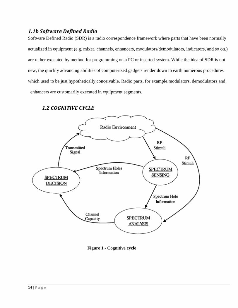
1.2 COGNITIVE CYCLE
Figure 1 - Cognitive cycle
15 | P a g e
1 .3 COGNITIVE RADIO’S CAPAB ILITIES
1.3a Spectrum Sensing
spectrum detecting is the capacity to quantify, sense and be mindful of the parameters identified with the
radio channel attributes, accessibility of range and transmit power, obstruction and clamor, radio's working
surroundings, client necessities and applications, accessible systems (frameworks) and hubs, nearby
strategies and other working confinements. It is done crosswise over Frequency, Time, Geographical
Space, Code and Phase.
1.3b Spectrum Analysis
Spectrum Analysis is taking into account range detecting which is dissecting the circumstance of a few
variables in the outer and inside radio environment, (for example, radio recurrence range use by neighboring
gadgets, client conduct and system state) and discovering the ideal correspondence convention and changing
recurrence or channel likewise. It is otherwise called channel estimation.
1.3c Spectrum Decision Making
Range Decision Making calls for reconfiguration for the channel and convention needed for always adjusting to
portable changing situations and modify ment of yield power or even adjustment of transmission parameters,
(for example, balance positions (e.g. low to high request QAM), variable image rates, distinctive channel coding
plans) and qualities by the Cognitive radio gadgets. CR ought to have the capacity to utilize numerous recieving
wires for obstruction nulling, limit build or extent augmentation.
16 | P a g e
1 .4 COGNITIVE RADIO’S KEY BENEFITS Cognitive Radio offers optimal diversity ( frequency, power, modulation, coding, space, time, polarization
and so on) which leads to:
Spectrum Efficiency- The basic purpose of implementing CR will allow the spectrum to be met in
future demand.
Higher bandwidth services- Interest of MBMS is always on the ascent which will be encouraged by
the execution of CR.
Graceful Degradation of Services - At the point when conditions will be not perfect, a agile
debasement of administration is given, rather than the less attractive complete and sudden loss of
administration. This highlight of CR is essential in giving administrations to the clients particularly when
they are portable and the base stations in contact are continually evolving.
Improved Quality of Service (QoS) (latency, data rate, cost etc) - Suitability, availability and reliability
of wireless services will improve from the user’s perspective.
Commercial Exploitation- CR advances range liberalization (makes it much less demanding to
exchange range between clients). Undoubtedly, a business case may exist for turning into a range agent,
whereby a third party oversees the exchange between supplier and demander and gets a commission.
Benefits to the Service Provider- More clients in the business sector and/or expanded data exchange
rates to existing clients. More players can come in the business sector.
Future-proofed product- A CR is able to change to services, protocols, modulation, spectrum etc. without
the need for a user and/or manufacturer to upgrade to a new device.
Common hardware platform- Makers will pick up from economies of scale in light of the fact that
they no more need to assemble various equipment variations, rather utilizing a solitary normal stage to run
an extensive variety of programming. This likewise supports in quick administration organization.
17 | P a g e
Flexible regulation-By using a form of policy database, regulation could be changed relatively quickly as
and when required, easing the burden on regulators.
Emergency service communications- Joint operations amid real occurrences would advantage
extraordinarily as police, flame, rescue vehicle and coastguard could be connected together in one radio
with every radio client detecting the range being utilized by alternate gatherings and reconfiguring itself.
Benefits to the Licensee- CR can prepare for range exchanging, where licensees would be permitted to
rent a bit of their range rights to outsiders on a worldly, spatial or other suitable premise to recover a percentage
of the cost of its 24hr-a-day permit.
[8]
18 | P a g e
Chapter 2
GNU RADIO AND USRP
19 | P a g e
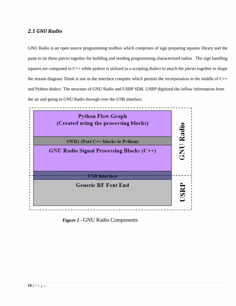
2.1 GNU Radio
GNU Radio is an open source programming toolbox which comprises of sign preparing squares library and the
paste to tie these pieces together for building and sending programming characterized radios . The sign handling
squares are composed in C++ while python is utilized as a scripting dialect to attach the pieces together to shape
the stream diagram. Drink is use as the interface compiler which permits the incorporation in the middle of C++
and Python dialect. The structure of GNU Radio and USRP SDR. USRP digitized the inflow information from
the air and going to GNU Radio through over the USB interface.
Figure 2 - GNU Radio Components

20 | P a g e
2.2 Universal Software Radio Peripheral(USRP)
Universal Software Radio Peripheral (USRP) is an adaptable ease stage for programming characterized
radios grew by Matt Ettus . USRP comprises of two fundamental sheets; the daughter board and the mother
board. The mother board comprises of four 12-bit Analog to Digital Converter (ADC) .
with testing rate up to 64 MS/s, four 14-bit Digital to Analog Converter (DAC) with velocity up to 128
MS/s, two Digital up Converter (DUC) to up believer the baseband sign to 128 MS/s before making an
interpretation of them to the chose yield recurrence, a programmable USB 2.0 controller for
correspondence in the middle of USRP and GNU Radio and a FPGA for actualizing four Digital Down
Converter (DDC) and high rate sign handling. It is fit to all the while transmit and get motion progressively
because of completely lucid in every testing clock and local oscillator.

21 | P a g e
Chapter 3
SPECTRUM SENSING
22 | P a g e
3.1 SPECTRUM SENSING Range detecting is the capacity to quantify, sense and be mindful of the parameters identified with the radio
channel qualities, accessibility of range and transmit power, obstruction and commotion, radio's working
surroundings, client prerequisites and applications, accessible systems (foundations) and hubs,
neighborhood arrangements and other working confinements. It is done crosswise over Frequency, Time,
Geographical Space, Code and Phase.
3.1a Spectrum Sensing Methods
A number of different methods are proposed for identifying the presence of signal transmission all of
which are in early development stage. They are:
Energy – Detection Based
Waveform Based
Cyclostationary – Based
Radio Identification Based
3.2 ENERGY DETECTION BASED SPECTRUM SENSING Energy Detection is the most well-known method for range detecting in light of its low computational and
usage complexities. It is a more non specific strategy as the recipients needn't bother with any information
on the essential client's sign. The sign is recognized by looking at the yield of the energy locator with an
edge which relies on upon the commotion floor. The imperative test with the vitality identifier based
detecting is the choice of the edge for recognizing essential clients. Alternate difficulties incorporate failure
to separate obstruction from essential clients and clamor and poor execution under low flag to-commotion
proportion values. PD (probability of detection) and PF (probability of false alarm) are the essential
variables for vitality based recognition which gives the data of the accessibility of the range.
23 | P a g e
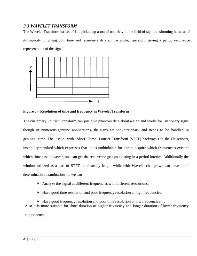
3.3 WAVELET TRANSFORM The Wavelet Transform has as of late picked up a ton of notoriety in the field of sign transforming because of
its capacity of giving both time and recurrence data all the while, henceforth giving a period recurrence
representation of the signal.
Figure 3 – Resolution of time and frequency in Wavelet Transform
The customary Fourier Transform can just give phantom data about a sign and works for stationary signs
though in numerous genuine applications, the signs are non- stationary and needs to be handled in
genuine time. The issue with Short Time Fourier Transform (STFT) backtracks to the Heisenberg
instability standard which expresses that it is unthinkable for one to acquire which frequencies exist at
which time case however, one can get the recurrence groups existing in a period interim. Additionally the
window utilized as a part of STFT is of steady length while with Wavelet change we can have multi
determination examination i.e. we can
Analyze the signal at different frequencies with different resolutions.
Have good time resolution and poor frequency resolution at high frequencies.
Have good frequency resolution and poor time resolution at low frequencies .
Also it is more suitable for short duration of higher frequency and longer duration of lower frequency
components.
24 | P a g e
3.4 WAVELET PACKET TRANSFORM For use of interest clamor is principally of high recurrence and the sign of hobby is basically of low
recurrence. The wavelet change decays the sign into rough guess (low recurrence) and subtle elements
(high recurrence) coefficients, the point of interest coefficients containing much clamor. The
straightforward system to denoise the signal will be to basically diminish the size of the subtle element
coefficients before utilizing them to remake the sign. This methodology is called thresholding. The point of
interest coefficients can't be made zero since they contain some essential highlights of the unique sign. The
two diverse methodologies which are typically connected to denoise are hard thresholding and delicate
thresholding.
Wavelet packet change is a speculation of wavelet change which continue part both low pass and high pass
sub-groups at all scales in the channel bank rough guess and usage. Thus it is suitable to finely recognize
the data in both high and low recurrence groups and subsequently is a perfect preparing device for non-
stationary time-variable sign.
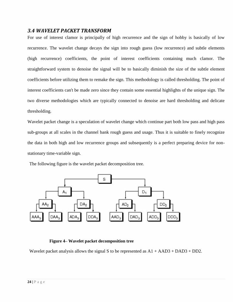
The following figure is the wavelet packet decomposition tree.
Figure 4– Wavelet packet decomposition tree
Wavelet packet analysis allows the signal S to be represented as A1 + AAD3 + DAD3 + DD2.
25 | P a g e
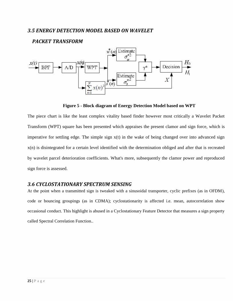
3.5 ENERGY DETECTION MODEL BASED ON WAVELET
PACKET TRANSFORM
Figure 5 - Block diagram of Energy Detection Model based on WPT
The piece chart is like the least complex vitality based finder however most critically a Wavelet Packet
Transform (WPT) square has been presented which appraises the present clamor and sign force, which is
imperative for settling edge. The simple sign x(t) in the wake of being changed over into advanced sign
x(n) is disintegrated for a certain level identified with the determination obliged and after that is recreated
by wavelet parcel deterioration coefficients. What's more, subsequently the clamor power and reproduced
sign force is assessed.
3.6 CYCLOSTATIONARY SPECTRUM SENSING At the point when a transmitted sign is tweaked with a sinusoidal transporter, cyclic prefixes (as in OFDM),
code or bouncing groupings (as in CDMA); cyclostationarity is affected i.e. mean, autocorrelation show
occasional conduct. This highlight is abused in a Cyclostationary Feature Detector that measures a sign property
called Spectral Correlation Function..

26 | P a g e
Figure 6- Cyclostationary Feature Detector
3.7 ADVANTAGES & DISADVANTAGES OF CYCLOSTATIONARY
SPECTRUM SENSING
Cyclostationary Spectrum Sensing performs better than Energy identification in view of its commotion
dismissal capacity. This happens on the grounds that clamor is absolutely irregular and does not display
any occasional conduct. When we have no former learning about essential client's waveform which is the
situation, all things considered, then best procedure is cyclostationary highlight discovery.

27 | P a g e
Chapter 4
RESULTS
&
INFERENCES

28 | P a g e
4.1 FM signal detected using RTL-SDR RTL-SDR antenna was connected to the DVB-T(Digital Video Broadcasting-Terrestrial) dongle and the
dongle was plugged to the Computer .After that I installed the SDR# software to receive the signal coming
from antenna.The obtained FM signal is shown below.To acess digital signal coming from dongle,I had to
install the zadig software.
Figure 7-set up zadig software
Figure 8-set up of SDR# Software
29 | P a g e
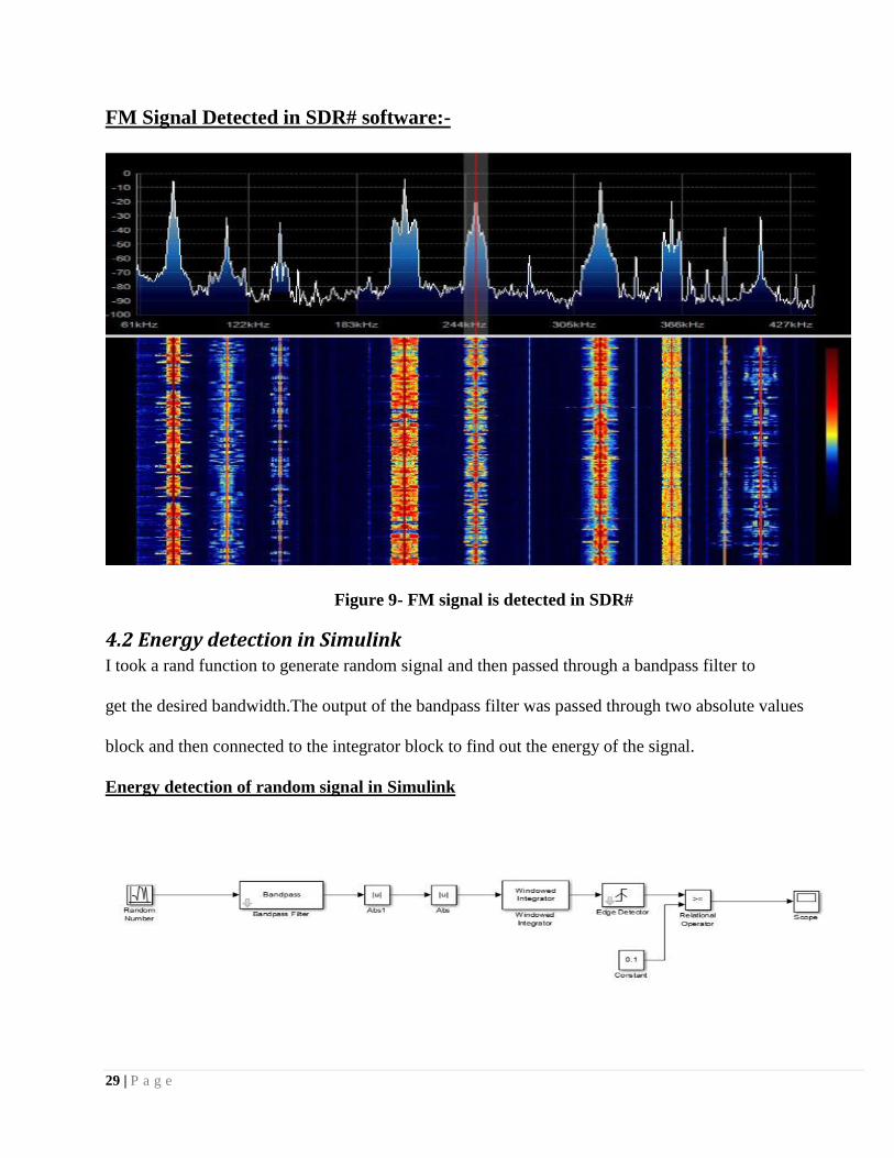
FM Signal Detected in SDR# software:-
Figure 9- FM signal is detected in SDR#
4.2 Energy detection in Simulink I took a rand function to generate random signal and then passed through a bandpass filter to
get the desired bandwidth.The output of the bandpass filter was passed through two absolute values
block and then connected to the integrator block to find out the energy of the signal.
Energy detection of random signal in Simulink
30 | P a g e
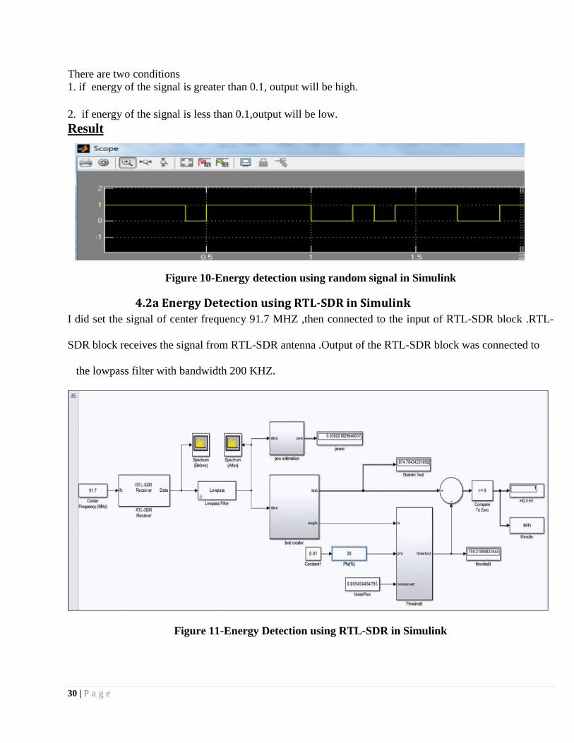
There are two conditions
1. if energy of the signal is greater than 0.1, output will be high.
2. if energy of the signal is less than 0.1,output will be low.
Result
Figure 10-Energy detection using random signal in Simulink
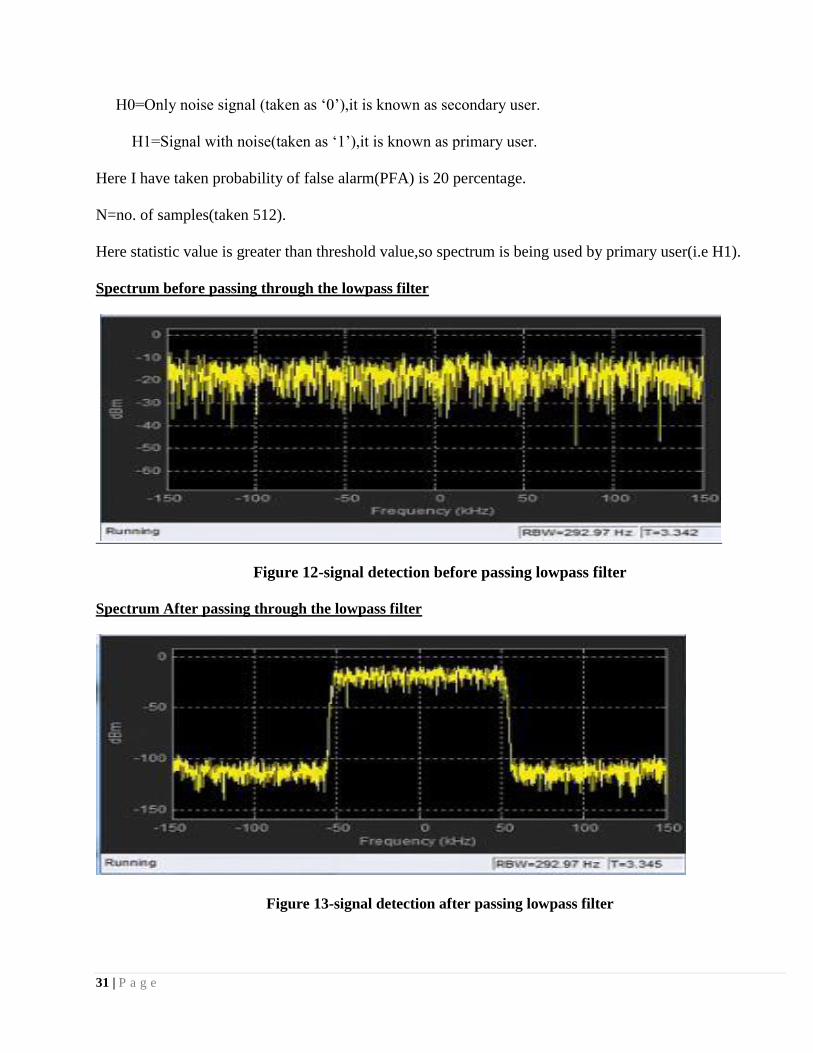
4.2a Energy Detection using RTL-SDR in Simulink
I did set the signal of center frequency 91.7 MHZ ,then connected to the input of RTL-SDR block .RTL-
SDR block receives the signal from RTL-SDR antenna .Output of the RTL-SDR block was connected to
the lowpass filter with bandwidth 200 KHZ.
Figure 11-Energy Detection using RTL-SDR in Simulink
31 | P a g e
H0=Only noise signal (taken as ‘0’),it is known as secondary user.
H1=Signal with noise(taken as ‘1’),it is known as primary user.
Here I have taken probability of false alarm(PFA) is 20 percentage.
N=no. of samples(taken 512).
Here statistic value is greater than threshold value,so spectrum is being used by primary user(i.e H1).
Spectrum before passing through the lowpass filter
Figure 12-signal detection before passing lowpass filter
Spectrum After passing through the lowpass filter
Figure 13-signal detection after passing lowpass filter
32 | P a g e
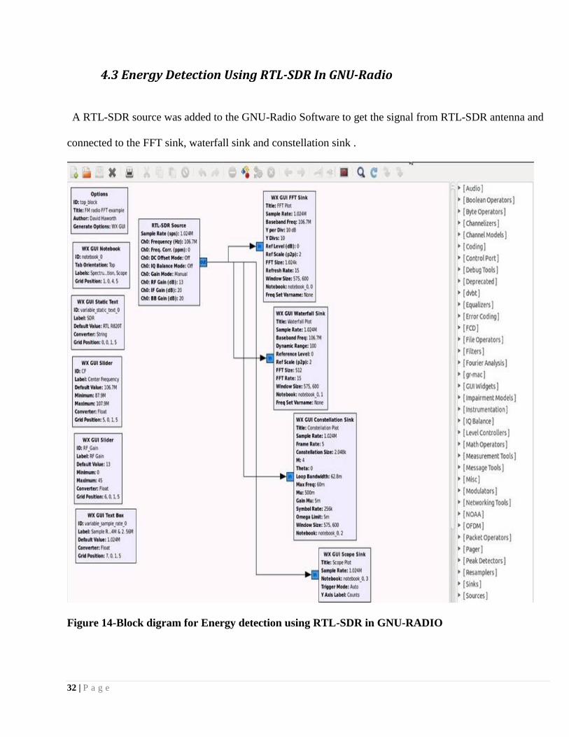
4.3 Energy Detection Using RTL-SDR In GNU-Radio
A RTL-SDR source was added to the GNU-Radio Software to get the signal from RTL-SDR antenna and
connected to the FFT sink, waterfall sink and constellation sink .
Figure 14-Block digram for Energy detection using RTL-SDR in GNU-RADIO

33 | P a g e
Figure 15- Waterfall plot shows the signal strength of the Spectrum.
Figure 15-waterfall plot
Figure 16- I t shows the fast fourier transform of the received signal by RTL-SDR Source.
Figure 16-FFT PLOT
34 | P a g e
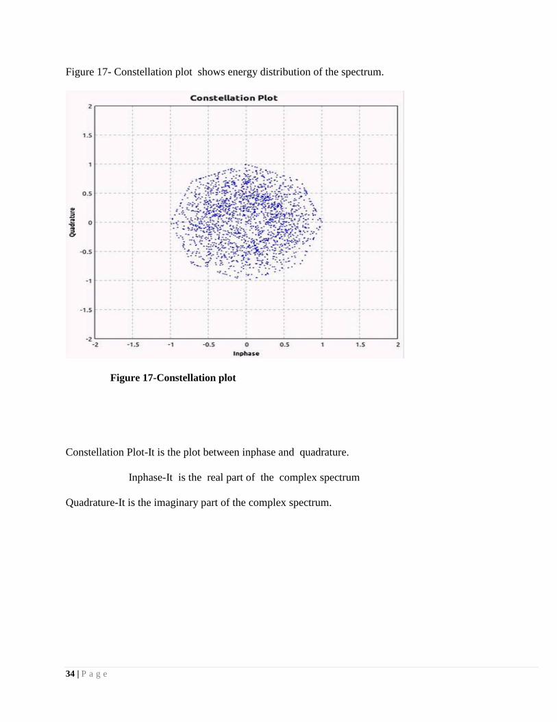
Figure 17- Constellation plot shows energy distribution of the spectrum.
Figure 17-Constellation plot
Constellation Plot-It is the plot between inphase and quadrature.
Inphase-It is the real part of the complex spectrum
Quadrature-It is the imaginary part of the complex spectrum.
35 | P a g e
Chapter 5
CONCLUSIONS
36 | P a g e
5.1 Conclusion
Energy Detection Spectrum detecting utilizing subjective radio strategy beats the conventional vitality
location system when the clamor was obscure which is the genuine situation. Consequently it is truly a
vigorous system for range detecting in Cognitive Radio when the commotion is obscure.
Signal and energy was detected using RTL-SDR in Simulink, SDR# and GNU Radio software. Cognitive
Radio did help us to know the spectrum wheather the spectrum is being used or not. Using cognitive radio
Method ,unused spectrum can be properly used.However, Cyclostationary spectrum sensing is much more
demanding computationally and is more complex than Energy detection spectrum sensing.
37 | P a g e
REFERENCES [1] Simon Haykin, “Cognitive Radio: Brain-Empowered Wire-less Communications”, IEEE
journal on Selected Areas in Communications.vol. 23, no. 2, February 2005,pp. 201-220.
[2] OFDM for Cognitive Radio: Merits and Challenges;Hisham A. Mahmoud, Tevfik Y¨ucek, and
H¨useyin Arslan; Department of Electrical Engineering, University of South
Florida
[3] IEEE 802 LAN/MAN Standards Committee 802.22 WG on WRANs (Wireless Regional
Area Networks).
[4] http://en.wikipedia.org/wiki/IEEE_802.22#cite_note-IEEE802r22-0.
[5] Federal Communications Commission, “ Spectrum Policy Task Force ,” Rep. ET Docket
no. 02-135, Nov. 2002.
[6] J. Mitola, Ed., “Special issue on software radio,” in IEEE Commun.Mag., May 1995.
[7] Cognitive Radio:Making Software Radios More Personal Joseph Mitola III and Gerald Q.Maguire, Jr.,
Royal Institute of Technology, IEEE Personal Communications August1999.
[8] Zhang Shi-bing and Qin Jin-jing, “Energy Detection Algorithm Based on Wavelet Packet
Transform under Uncertain Noise for Spectrum Sensing”, IEEE Conference of Wi3COM
2010.
[9] “A Survey of Spectrum Sensing Algorithms for Cognitive Radio Applications”, Communications
Surveys & Tutorials, IEEE 2009 BY Tevfik Yucek and Huseyin Arslan.
[10] Edward Peh and Ying-Chang Liang, “Optimization for Cooperative Sensing in
Cognitive Radio Networks”, IEEE Communications Society WCNC 2007 proceedings.

38 | P a g e
[11] Spectrum sensing using cyclostationarity properties and applications to IEEE 802.22
WRAN; By Hou Shin Chen, Wen Gao, David G Deut.
[12] Co operative Cyclostationarity Spectrum Sensing in Cognitive Radio at Low SNR Regimes; By
Mahsa Darakhshani, Masoumah Nasiri Kenari , Tho Le ngoe, ieee icc 2010.
[13] Peter G. Cook ,Wayne Bonser. “Architectural Overview of th SPEAKeasy System”. IEEE Journal On
Selected Areas In Communications, Vol. 17, No. 4, April 1999.
[14] Amalia Roca, “Implementation of a WiMAX simulator in Simulink”.Thesis for Diploma In Institiut
Of Nachrichtentechnik Und Hochfrequenztechnik, Torreblanca Castellón, Spain, February 2007.