signal relays axicom sheets/tyco...n telecom/signal relay (dry circuit, test access, ringing) n slim...
TRANSCRIPT
08-2011, Rev. 0811www.te.com© 2011 Tyco Electronics Corporation,a TE Connectivity Ltd. company
Datasheets and product specification according to IEC 61810-1 and to be used only together with the ‘Definitions’ section.
Datasheets and product data is subject to the terms of the disclaimer and all chapters of the ‘Definitions’ section, available at http://relays.te.com/definitions
Datasheets, product data, ‘Definitions’ sec-tion, application notes and all specifications are subject to change.
1
AXICOMSignal Relays
n Telecom/signal relay (dry circuit, test access, ringing)n Slim line 15x7.5mm (.59x.295”)n Switching current 2An 2 form C bifurcated contacts (2 CO)n High sensitive 24V and 48V coil versionsn Meets Telcordia GR 1089, FCC Part 68 and ITU-T K20, ≥ 2500V
between coil and contacts
Typical applications Communications equipment, linecard application – analog, ISDN, xDSL, PABX, voice over IP, office and business equipment, measurement and control equipment, consumer electronics, set top boxes, HiFi, medical equipment
Approvals UL 508 File No. E 111441Technical data of approved types on request
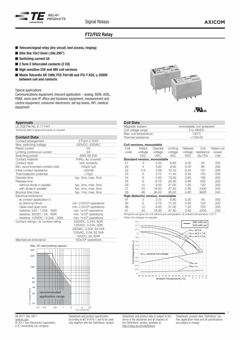
Contact Data Contact arrangement 2 Form C (CO)Max. switching voltage 220VDC, 250VACRated current 2A Limiting continuous current 2ASwitching power 60W, 62.5VAContact material PdRu, Au covered Contact style twin contacts Min. recommended contact load 100µV/1µA Initial contact resistance <50mΩ Thermoelectric potential <10µVOperate time typ. 3ms, max. 5ms Release time without diode in parallel typ. 2ms, max. 5ms with diode in parallel typ. 4ms, max. 5ms Bounce time max. typ. 1ms, max. 5msElectrical endurance at contact application 0 (≤ 30mV/≤10mA) min. 2.5x10⁶ operations cable load open end min. 2.0x10⁶ operations resistive, 24V / 1.25A - 30W min. 1x10⁵ operations resistive, 30VDC / 2A - 60W min. 1x10⁵ operations resistive, 125VDC / 0.24A - 30W min. 1x10⁵ operationsContact ratings, UL contact rating 220VDC, 0.24A, 60W 125VDC, 0.24A, 30W 250VAC, 0.25A, 62.5VA 125VAC, 0.5A, 62.5VA 30VDC, 2A, 60WMechanical endurance 100x106 operations
Coil Data Magnetic system monostable, non polarizedCoil voltage range 3 to 48VDCMax. coil temperature 150°C Thermal resistance <125K/W
Coil versions, monostable Coil Rated Operate Limiting Release Coil Rated coil code voltage voltage voltage voltage resistance power VDC VDC VDC VDC Ω±10% mWStandard version, monostable 21 3 2.25 6.80 0.30 45 200 29 4 3.00 9.00 0.40 80 200 22 4.5 3.38 10.10 0.45 101 200 23 5 3.75 11.20 0.50 125 200 24 6 4.50 13.50 0.60 180 200 25 9 6.75 20.30 0.90 405 200 26 12 9.00 27.00 1.20 720 200 27 24 18.00 47.50 2.40 2400 240 28 48 36.00 95.00 4.80 9600 240High dielectric version, monostable 91 3 2.25 6.80 0.30 45 200 93 5 3.75 11.20 0.50 125 200 96 12 9.00 27.00 1.20 720 200 97 24 18.00 47.50 2.40 2400 240All figures are given for coil without pre-energization, at ambient temperature +23°C.Other coil voltages on request.
FT2/FU2 Relay
DC current [A]
DC
vol
tage
[VD
C]
Max. DC load breaking capacity
108-98004 Rev. F
All specifications subject to change. Consult Tyco Electronics for latest specifications. 5 of 13
Telecom-, Signal and RF Relays
FT2/FU2 Relay
Coil Operating Range
Unom = Nominal coil voltage
Umax. = Upper limit of the operative range of the coil voltage (limiting voltage) when coils are continously energized
Uop. min. = Lower limit of the operative range of the coil voltage (reliable operate voltage)
Urel. min. = Lower limit of the operative range of the coil voltage (reliable release voltage)
0
0.2
0.4
0.6
0.8
1
1.2
1.4
1.6
1.8
2
2.2
2.4
2.6
-60 -50 -40 -30 -20 -10 0 10 20 30 40 50 60 70 80 90 100
110
120
130
140
Unom. nominal coil voltage
Uop. min.
Urel. min.
Umax. at 0 A
Umax. at 2 x 2 AUmax. at 2 x 1 A
Ambient Temperature [°C]
Coi
l Vol
tage
[U/U
nom
]
200 mW coil240 mW coil
0.0
0.2
0.4
0.6
0.8
1.0
1.2
1.4
1.6
1.8
2.0
2.2
2.4
2.6
-60 -50 -40 -30 -20 -10 0 10 20 30 40 50 60 70 80 90 100 110 120 130 140
Unom. nominal coil voltage
Uop. min.
Urel. min.
Umax. at 0 A
Umax. at 2 x 2 AUmax. at 2 x 1 A
Ambient Temperature [°C]
Coi
l Vol
tage
[U/U
nom
]
300 mW coil
Z

08-2011, Rev. 0811www.te.com© 2011 Tyco Electronics Corporation,a TE Connectivity Ltd. company
Datasheets and product specification according to IEC 61810-1 and to be used only together with the ‘Definitions’ section.
Datasheets and product data is subject to the terms of the disclaimer and all chapters of the ‘Definitions’ section, available at http://relays.te.com/definitions
Datasheets, product data, ‘Definitions’ sec-tion, application notes and all specifications are subject to change.
2
AXICOMSignal Relays
FT2/FU2 Relay (Continued)
Insulation standard high dielectricInitial dielectric strength between open contacts 1000Vrms 1500Vrms between contact and coil 1500Vrms 4000Vrms between adjacent contacts 1500Vrms 1800VrmsInitial surge withstand voltage between open contacts 1500V 2500V between contact and coil 2500V 6000V between adjacent contacts 1500V 2500VInitial insulation resistance between insulated elements >109Ω >109ΩCapacitance between open contacts max. 4pF between contact and coil max. 1pF between adjacent contacts max. 1pF Cross talk at 100MHz/900MHz -30.6dB/-13.7dB Insertion loss at 100MHz/900MHz -0.02dB/-0.50dB Voltage standing wave ratio (VSWR) at 100MHz/900MHz 1.02 / 1.27
Other Data Material compliance: EU RoHS/ELV, China RoHS, REACH, Halogen content refer to the Product Compliance Support Center at www.te.com/customersupport/rohssupportcenterAmbient temperature -55°C to +85°C Thermal resistance <125K/W Category of environmental protection IEC 61810 RT III - immersion cleanable Degree of protection, IEC 60529 IP 67, immersion cleanable Vibration resistance (functional) 10g, 10 to 500Hz Shock resistance (functional), half sinus 11ms 15g Shock resistance (destructive), half sinus 0.5ms 500gWeight max. 3gResistance to soldering heat THT IEC 60068-2-20 265°C/10s Resistance to soldering heat SMT IEC 60068-2-58 265°C/10s Moisture sensitive level, JEDEC J-Std-020D MSL3 Ultrasonic cleaning not recommendedPackaging/unit THT version tube/50 pcs., box/2000 pcs. SMT short terminals reel/500 pcs.,box/2500 pcs. SMT long terminals reel/400 pcs.,box/2000 pcs.
Coil Data (continued)
Coil versions, monostable Coil Rated Operate Limiting Release Coil Rated coil code voltage voltage voltage voltage resistance power VDC VDC VDC VDC Ω±10% mWHigh dielectric Australia version, monostable 71 3 2.25 5.50 0.30 30 300 73 5 3.75 9.20 0.50 83 300 76 12 9.00 22.10 1.20 480 300All figures are given for coil without pre-energization, at ambient temperature +23°C.Other coil voltages on request.
Umax upper limit of the operative range of the coil voltage (limiting voltage) when coils are continuously energized
Uop min lower limit of the operative range of the coil voltage (reliable operate voltage)Urel min lower limit of the operative range of the coil voltage (reliable release voltage)
108-98004 Rev. F
All specifications subject to change. Consult Tyco Electronics for latest specifications. 5 of 13
Telecom-, Signal and RF Relays
FT2/FU2 Relay
Coil Operating Range
Unom = Nominal coil voltage
Umax. = Upper limit of the operative range of the coil voltage (limiting voltage) when coils are continously energized
Uop. min. = Lower limit of the operative range of the coil voltage (reliable operate voltage)
Urel. min. = Lower limit of the operative range of the coil voltage (reliable release voltage)
0
0.2
0.4
0.6
0.8
1
1.2
1.4
1.6
1.8
2
2.2
2.4
2.6
-60 -50 -40 -30 -20 -10 0 10 20 30 40 50 60 70 80 90 100
110
120
130
140
Unom. nominal coil voltage
Uop. min.
Urel. min.
Umax. at 0 A
Umax. at 2 x 2 AUmax. at 2 x 1 A
Ambient Temperature [°C]
Coi
l Vol
tage
[U/U
nom
]200 mW coil240 mW coil
0.0
0.2
0.4
0.6
0.8
1.0
1.2
1.4
1.6
1.8
2.0
2.2
2.4
2.6
-60 -50 -40 -30 -20 -10 0 10 20 30 40 50 60 70 80 90 100 110 120 130 140
Unom. nominal coil voltage
Uop. min.
Urel. min.
Umax. at 0 A
Umax. at 2 x 2 AUmax. at 2 x 1 A
Ambient Temperature [°C]
Coi
l Vol
tage
[U/U
nom
]
300 mW coil
PCB layout TOP view on component side of PCB
Terminal assignmentTOP view on component side of PCB
THT version SMT, long terminals SMT, short terminals

08-2011, Rev. 0811www.te.com© 2011 Tyco Electronics Corporation,a TE Connectivity Ltd. company
Datasheets and product specification according to IEC 61810-1 and to be used only together with the ‘Definitions’ section.
Datasheets and product data is subject to the terms of the disclaimer and all chapters of the ‘Definitions’ section, available at http://relays.te.com/definitions
Datasheets, product data, ‘Definitions’ sec-tion, application notes and all specifications are subject to change.
3
AXICOMSignal Relays
FT2/FU2 Relay (Continued)
Dimensions
15.0±0.05 7.5±0.05
5.080.5
9.6±
0.03
3.3±
0.03
0.35
±0.
03
15.0±0.05 7.5±0.05
5.080.5
10.0
±0.
15
9.2±0.2
15.0±0.05 7.6±0.05
5.080.5
10.0
±0.
15
7.5±0.2coplanarity ≤0.1mm coplanarity ≤0.1mm
THT version SMT, long terminals SMT, short terminals
15.0±0.05 7.5±0.05
5.080.5
9.6±
0.03
3.3±
0.03
0.35
±0.
03
15.0±0.05 7.5±0.05
5.080.5
10.0
±0.
15
9.2±0.2
15.0±0.05 7.6±0.05
5.080.5
10.0
±0.
15
7.5±0.2coplanarity ≤0.1mm coplanarity ≤0.1mm
15.0±0.05 7.5±0.05
5.080.5
9.6±
0.03
3.3±
0.03
0.35
±0.
03
15.0±0.05 7.5±0.05
5.080.5
10.0
±0.
15
9.2±0.2
15.0±0.05 7.6±0.05
5.080.5
10.0
±0.
15
7.5±0.2coplanarity ≤0.1mm coplanarity ≤0.1mm
Processing
full line: typicaldotted line: process limits
external preheating
240°C
180°C
130°C
100°C
forced cooling
20 to 40s
Time [s]
Tem
pera
ture
[°C
]
Vapour phase solderingtemperature/time profile(lead and housing peak temp.)
Recommended soldering conditionsVapour phase soldering
Time [s]
Tem
pera
ture
[°C
]
Recommended reflow soldering profile
Infrared solderingtemperature/time profile(lead and housing peak temp.)
Time [s]
Tem
pera
ture
[°C
]
Resistance to soldering heat
Infrared solderingtemperature/time profile(lead and housing peak temp.)
Packing
Tape and reel for SMT version with long terminals
Tape and reel for SMT version with short terminals
Reel dimensions
08-2011, Rev. 0811www.te.com© 2011 Tyco Electronics Corporation,a TE Connectivity Ltd. company
Datasheets and product specification according to IEC 61810-1 and to be used only together with the ‘Definitions’ section.
Datasheets and product data is subject to the terms of the disclaimer and all chapters of the ‘Definitions’ section, available at http://relays.te.com/definitions
Datasheets, product data, ‘Definitions’ sec-tion, application notes and all specifications are subject to change.
4
AXICOMSignal Relays
FT2/FU2 Relay (Continued)
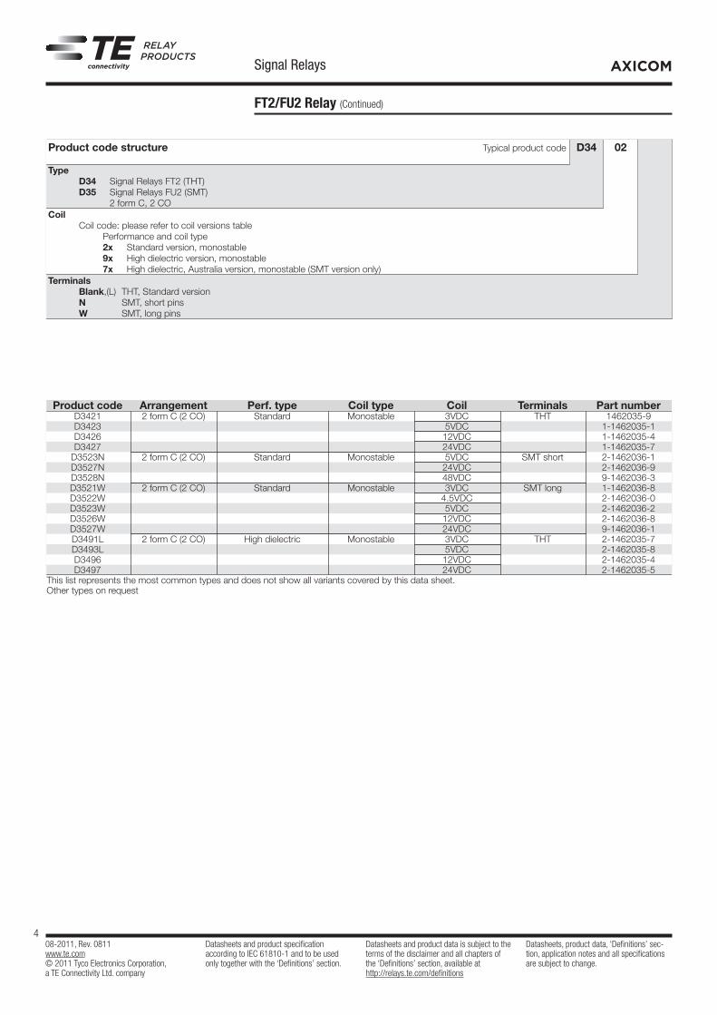
Product code structure Typical product code D34 02
Type D34 Signal Relays FT2 (THT) D35 Signal Relays FU2 (SMT) 2 form C, 2 COCoil Coil code: please refer to coil versions table Performance and coil type 2x Standard version, monostable 9x High dielectric version, monostable 7x High dielectric, Australia version, monostable (SMT version only)Terminals Blank,(L) THT, Standard version N SMT, short pins W SMT, long pins
Product code Arrangement Perf. type Coil type Coil Terminals Part number D3421 2 form C (2 CO) Standard Monostable 3VDC THT 1462035-9 D3423 5VDC 1-1462035-1 D3426 12VDC 1-1462035-4 D3427 24VDC 1-1462035-7 D3523N 2 form C (2 CO) Standard Monostable 5VDC SMT short 2-1462036-1 D3527N 24VDC 2-1462036-9 D3528N 48VDC 9-1462036-3 D3521W 2 form C (2 CO) Standard Monostable 3VDC SMT long 1-1462036-8 D3522W 4.5VDC 2-1462036-0 D3523W 5VDC 2-1462036-2 D3526W 12VDC 2-1462036-8 D3527W 24VDC 9-1462036-1 D3491L 2 form C (2 CO) High dielectric Monostable 3VDC THT 2-1462035-7 D3493L 5VDC 2-1462035-8 D3496 12VDC 2-1462035-4 D3497 24VDC 2-1462035-5 This list represents the most common types and does not show all variants covered by this data sheet. Other types on request