signaling and equalization overview for sas - t10 · introduction • simulation model overview •...
TRANSCRIPT

Title: Overview of Signaling and Equalization Methods Considered in OIF and IEEE 802.3 ap for 6G and 10 Gbps Sources: Joe Caroselli and Mike Jenkins
LSI LogicDate: May 26, 2005Abstract:
The presentation gives an overview and comparison of signaling methods and equalization techniques considered for backplane transceivers at 6 and 10 Gbps in other standards bodies. In particular, NRZ, PAM-4 Duobinary, and PR4 are the signaling schemes considered and linear and decision feedback equalization are discussed.

Introduction• Many signaling techniques have been examined
– NRZ– PAM-4– Duobinary– PR4
• Several equalization techniques have been considered– FIR linear filter on TX or RX– Continuous time linear equalizer in Rx– Decision Feedback Equalizer in Rx

Introduction
• Simulation Model Overview• Linear Equalizer versus Decision Feedback
Equalization (DFE)• NRZ vs. PAM-4• NRZ, Duobinary, and PR4

Simulator Overview

Bit By BitSimulator
(Eye Diagrams, Jitter Tolerance, Frequency Offset, Timing, Loop Convergence)
Semi-AnalyticSimulator
(BER, Statistical Eye)
AnalyticSimulator
(Architecture Determination)
Speed
Ease of Modification
Three System Modeling Approach
Com
plexity

• Includes– Inter-symbol Interference– Tx Jitter– Electronics (White) Noise– Crosstalk
• Does Not Include– Receiver Sensitivity– Duty Cycle Distortion– Other Sources of DJ
Analytic Model

Required SNRSNR Required at Slicer for 10-15 BER
2
2min
σdSNR =
⎟⎟⎠
⎞⎜⎜⎝
⎛≈
2221Pr SNRerfcerr
•Approximately 24dB is required for an error rate of 10-15

Overview of Simulations
• Equalization architectures with a linear FIR feedforward(FF) filter in the TX, and a decision feedback (FB) equalizer in the Rx are compared.
• The number of taps in the feedforward and feedback equalizers are varied.
• The effect of one worst-case near-end crosstalk aggressor is considered.
• A simple RC model with pole at 0.75*baud rate is used for the transmitter.
• Mellitz capacitor-like package model included on both transmitter and receiver.

Parameters Used
• Only DJ is from ISI– No DCD, PJ included
• 0.010UI σ RJ added, unless otherwise noted– Not more than 13.4ps peak-to-peak RJ at 8.5Gbps data
rate with probability 1-10-12
– Not more than 15.6ps peak-to-peak RJ max at 8.5Gbps data rate with probability 1-10-15
• Signal-To-Electronics Noise Ratio 45dB, unless otherwise noted
• Crosstalk added as noted• Ideal receiver sensitivity assumed

Decision Feedback Equalization versus Linear Feedforward Equalization
Adaptive Feedback Equalizer
Adaptive Feedback Equalizer
++--
ka
Linear Equalizer
Linear Equalizer
ka
DFE Receiver
Receiver with Linear Equalization

Ideal DFE versus Ideal Linear EqualizationBest and Worst Case Phases Versus Distance; No Jitter or XT
•DFE has an advantage over linear equalizer at the ideal sampling phase because it results in less noise enhancement.
•DFE is less affected by choice of sampling phase and thus more resistant to jitter.

CrosstalkNear-End and Far-End Crosstalk Frequency Responses

•The benefit of DFE is shown to grow with the amount of high frequency noise and the amount of high frequency boost required to compensate for the channel’s attenuation.
Ideal DFE versus Ideal Linear EqualizationBest and Worst Case Phases Versus Distance with Jitter and NEXT

Far-End CrosstalkEffect of Crosstalk Phase

Near-End CrosstalkEffect of Worst Phase NEXT

SNR at Slicer vs. Sampling PositionLSI 36” Trace, 6.0 Gbps; 0.026UI Random Jitter
•Even without crosstalk, the benefit of DFE can be seen as the sampling position moves away from the center of the eye. This results in improved jitter tolerance.

NRZ vs. PAM-4

Introduction• NRZ is standard 2–level signaling used in most backplane
transceivers today.• PAM-4 is four level signaling at half the bit rate with each
level corresponding determined by two consecutive bits.• NRZ can perform better than PAM-4 even when the
channel loss between the Nyquist frequency of PAM-4 and that of NRZ is greater than 9.5dB.
• NRZ and PAM-4 with a linear FIR feedforward (FF) filter and a decision feedback (FB) equalizer are compared for such a channel.
• The number of taps in the feedforward and feedback equalizers are varied.
• The effect of near-end crosstalk is observed.

Frequency ResponseActual Channel (from Steve Anderson, Xilinx)
•Difference between response at 5.15GHz (Nyquist frequency of NRZ) and 2.58GHz (Nyquistfrequency of PAM-4) is about 10dB.
•PAM-4 is often thought to perform better if the difference is greater >9.5dB.1 This figure comes from the fact that an ideal PAM-4 signal has three eyes each of which have roughly 1/3 the vertical opening of an ideal NRZ eye.
1 Howard Johnson, “Multi-Level Signaling,” DesignCon 2000.
-23dB @5.15GHz
-13dB @2.58GHz

Pulse ResponseBased on Channel similar to IEEE 802.3ap Channel Model
•Pulse response generated assuming single pole TX lowpass filter with corner at ¾ * baud rate.
•Dots are separated by one UI and therefore represent potential ISI.
•Only one significant point of pre-cursor ISI.
•Has long slowly decaying tail with many points of post-cursor ISI. This would require >15 DFE taps to completely address.

Description of Results
• SNR at optimal sampling point is shown. No measurement of horizontal eye opening is presented.
• x-axis shows number of feedback taps used• Each line represents a different number of feed-
forward (FF) equalizer taps used in the TX• Each color represents a different signaling
scheme.• Crosstalk is assumed to occur at the same
frequency as the signal. The worst case crosstalk phase at the ideal sampling point is selected.
• All tap values are ideal.

NRZ vs PAM-410.3125Gbps; No Crosstalk
•Transmit equalization is FIR with varying number of taps to address pre-cursor ISI.
•With one tap post-emphasis (D-α) and 5 feedback taps, neither PAM-4 nor NRZ provides enough SNR to function. However,PAM4 has about 1.5dB more SNR.
•To get BER <10-15 with one tap post-emphasis, PAM-4 requires 6 feedback taps while NRZ requires 8.
•As number of DFE taps increases, performance of NRZ relative to PAM4 increases.
( )∑
∑−
=
−=
=
−−
+
−
1
0
1
0
)1(
1k
nn
kn
n
nkn
k
abs
DD
α
α

Pulse Response at 10.3125GbpsOne Tap Post-Emphasis
•Transmit equalization is two tap FIR to address pre-cursor ISI (one tap post-emphasis).
•Precursor ISI is greatly reduced.
•First five post-cursor ISI samples can be reduced by a 5-tap DFE.
•A long slowly decaying tail of post-cursor ISI still remains.

NRZ vs PAM-410.3125Gbps; No Crosstalk; With One Tap PostCursor FF Equalization
•Transmit equalization is a FIR with one tap to address post-cursor ISI and varying number of taps to address pre-cursor ISI.
•With one tap post-emphasis and one tap pre-emphasis
(-βD2 +D-α)
and 5 feedback taps, both PAM-4 and NRZ provide enough SNR to function. However, NRZ has about 1dB more SNR than PAM-4.
•As the number of feedback taps increases, advantage of NRZ over PAM4 increases.
NRZ with 3 tap FIR in TX and 5 tap DFE
PAM-4 with 3 tap FIR in TX and 5 tap DFE

•Transmit equalization is two tap FIR to address post-cursor ISI (one tap pre-emphasis).
•Post-cursor ISI is greatly reduced so that only three significant post-cursor ISI points remain.
•One tap of pre-emphasis can almost completely remove long tail that would require almost 15 taps of DFE.
•Pre-cursor ISI is reduced but still significant.
Pulse Response at 10.3125GbpsOne Tap Pre-Emphasis
1 tap PreEmphasis

•Transmit equalization is three tap FIR with one tap to address pre-cursor ISI and one tap to address post-cursor ISI. (One tap post-emphasis and one tap pre-emphasis.)
•Pre-cursor ISI is now also significantly reduced.
Pulse Response at 10.3125GbpsThree Tap FIR (One Tap Pre-Emphasis and One Tap Post-Emphasis)

Near-End Crosstalk Frequency ResponsesFrom Xilinx
•One channel of NEXT will be added to the simulations.
•Crosstalk is assumed to occur at the same frequency as the signal.
•The worst case crosstalk phase at the ideal sampling point is selected.

NRZ vs PAM-410.3125Gbps; NEXT; With One Tap PostCursor FF Equalization
•With NEXT and three tap FIR, NRZ meets SNR goal with one DFE tap and PAM-4 requires two.
•With NEXT, performance of three tap FIR and 5 DFE taps decreases about 2.5dB.
•NRZ advantage over PAM-4 has decreased to about 0.5dB with 5 tap DFE.
NRZ with 3 tap FIR in TX and 5 tap DFE
PAM-4 with 3 tap FIR in TX and 5 tap DFE

ConclusionNRZ vs. PAM-4
• Although channel has greater than 9.5dB loss between Nyquistfrequencies of PAM-4 and NRZ, NRZ can perform better depending on the detection scheme.
• Performance of NRZ improves relative to PAM-4 as the number of DFE taps increase.
• A three tap FIR with one tap dedicated to post-emphasis and one tap devoted to pre-emphasis is recommended. This can greatly reduce pre-cursor ISI and mostly remove a long slowly decaying tail on the pulse response. A few points of significant post-cursor ISI remain and can be removed with a few taps of DFE.
• With pre-emphasis tap, number and weight of feedback taps is reduced resulting in improved error propagation.

NRZ, Duobinary, and PR4Overview

Introduction• Overview of signaling schemes
– NRZ, Duobinary, and PR4• Presentation of results

NRZ SignalingTrying to Removing All ISI Through Equalization
• Our primary equalization goal has been to eliminate intersymbolinterference (ISI).
• A combination of a TX FIR filter and a DFE in the Rx are used to mitigate the ISI.
• The goal of removing ISI is to make detection possible with a reasonable complexity.

• 1+D Channel– Samples at
• time 0 and 1 are 1• 0 everywhere else.
• Appears to be a reasonable fit for channels at this data rate.
DuobinaryIdeal versus Channel Pulse Response

Partial Response – Class IVPulse Response
• Does not resemble our channel pulse response.

Frequency Response ComparisonNRZ and Duobinary
• Ideal NRZ equalization target is flat spectrum.
• NRZ requires a lot of high frequency boost.
• Duobinary’s 1+D equalization target has a null at the Nyquistfrequency. It is a better match to the channel at high frequencies and consequently requires less high frequency boost.
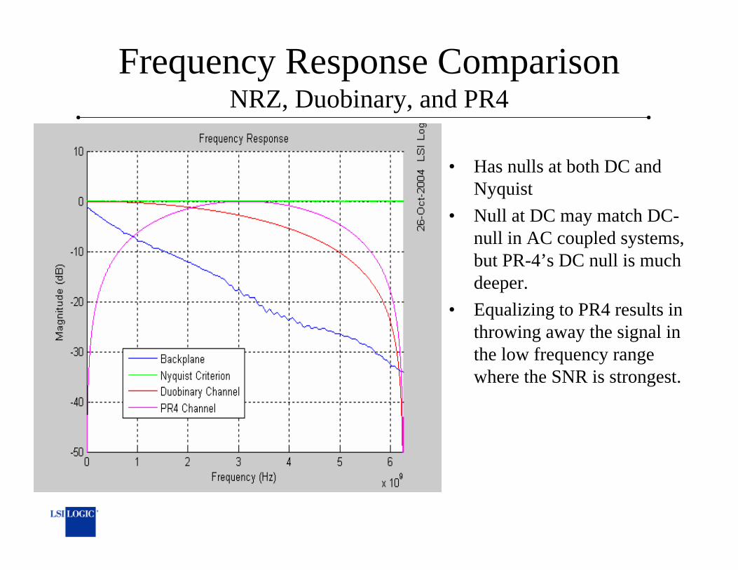
Frequency Response ComparisonNRZ, Duobinary, and PR4
• Has nulls at both DC and Nyquist
• Null at DC may match DC-null in AC coupled systems, but PR-4’s DC null is much deeper.
• Equalizing to PR4 results in throwing away the signal in the low frequency range where the SNR is strongest.

DuobinaryIdeal Eye Diagram
• No transitions from highest to lowest signal levels in adjacent bits.
• Notice that slicer value that results in highest jitter tolerance is not the slicer level that results in best noise tolerance.

PR4Eye Diagram
• Horizontal eye opening in ideal eye diagram is reduced compared to 1+D target.
• Any signal level can transition to any other signal level in adjacent bit.
• Even in ideal case, without MLSD, eye exhibits very little tolerance to jitter.

Summary of Results

SNR ComparisonIntel Backplanes
18.269817.306215.246114.064919.730418.442719.045116.325720.4595Intel T20
18.918818.171115.069613.808420.478318.69620.216817.829521.3521Intel T12
19.414317.795111.818711.68420.126219.68520.046219.671521.862Intel T1
21.044821.043617.179616.702822.389721.886620.177318.837824.2586Intel M20
20.56519.226914.354813.661522.121421.388221.842821.384324.2043Intel M1
22.970922.13713.607712.553424.786724.103621.467817.933724.421Intel B20
23.576322.970112.907211.872225.531224.067324.293620.664725.4387Intel B12
22.14821.991610.535510.0224.719423.890424.718923.742825.75Intel B1
PR4 5FF+5DFE
PR4 5FF+3DFE
PR4 3FF+5DFE
PR4 3FF+3DFE
DB 4FF+5DFE
DB 4FF+3DFE
DB 3FF+5DFE
DB 3FF+3DFE
NRZ 3FF+5DFEBP

SNR ComparisonTyco Backplanes
24.292122.514217.500916.979326.065223.711225.866223.39426.6822Tyco 7
23.080621.600617.052915.634924.399123.334422.331919.935725.4634Tyco 6
26.714125.206517.498915.926427.89627.343123.617620.500328.8032Tyco 5
24.820223.806616.38314.676526.149625.884819.958316.721327.3838Tyco 4
23.156422.459614.889613.061924.655924.490417.026114.741224.7924Tyco 3
15.430213.655915.424513.650317.854915.447417.854215.441726.7208Tyco 2
23.685223.162415.361513.721825.375225.308118.087815.557926.4184Tyco 1
PR4 5FF+5DFE
PR4 5FF+3DFE
PR4 3FF+5DFE
PR4 3FF+3DFE
DB 4FF+5DFE
DB 4FF+3DFE
DB 3FF+5DFE
DB 3FF+3DFE
NRZ 3FF+5DFEBP

SNR ComparisonMolex and Xilinx Backplanes
21.040520.219115.235813.333322.980322.824418.367315.359623.6875Anderson
22.648922.319116.923815.370424.304724.125219.117517.295825.2929Molex o5
22.651522.145416.772715.123924.226623.902418.999317.207125.1958Molex o4
22.495622.032916.190114.58624.072823.683218.810616.7525.0651Molex o3
22.68322.303617.001115.478524.268223.941919.121417.541525.224Molex o2
22.409921.510515.639913.728623.945923.552918.951816.052924.9085MoLex i5
22.27820.966416.521814.50423.756323.050718.735216.802324.635MoLex i4
22.304221.309215.924414.067323.730423.094818.794316.436924.7216MoLex i3
22.384821.451316.812914.924823.880523.300418.919317.181524.809MoLex i2
PR4 5FF+5DFE
PR4 5FF+3DFE
PR4 3FF+5DFE
PR4 3FF+3DFE
DB 4FF+5DFE
DB 4FF+3DFE
DB 3FF+5DFE
DB 3FF+3DFE
NRZ 3FF+5DFEBP

Required Number of DFE TapsTo Achieve 24dB SNR
Tyco Backplanes
3044Tyco 6
<=1<=1<=1Tyco 5
42<=1Tyco4
1033Tyco3
10020<=1Tyco 2
63<=1Tyco 1
5 tap FF4 tap FF3 tap FF
PR4DBNRZBP

Required Number of DFE TapsTo Achieve 24dB SNR
Intel Backplanes
>100>100>100Intel T20
>100100100Intel T12
202010Intel T1
20205Intel M20
1064Intel M1
834Intel B20
634Intel B12
843Intel B1
5 tap FF4 tap FF3 tap FF
PR4DBNRZBP

Required Number of DFE TapsTo Achieve 24dB SNR
Molex and Xilinx Backplanes
>100208Anderson
1003<=1Molex o5
1004<=1Molex o4
1005<=1Molex o3
1004<=1Molex o2
10062Molex i5
100102Molex i4
10082Molex i3
10062Molex i2
5 tap FF4 tap FF3 tap FF
PR4DBNRZBP

ResultsTyco 5 Backplane
100
101
102
5
10
15
20
25
30
35
40
Number of Feedback Taps
SNR
at S
licer
(dB
)
Tyc o 5
NRZ: 1 pre + 0 post FIR FFNRZ: 1 pre + 1 post FIR FFNRZ: 1 pre + 2 post FIR FFNRZ: 1 pre + 3 post FIR FFNRZ: 2 pre + 3 post FIR FFDB: 1 pre + 0 post FIR FFDB: 1 pre + 1 post FIR FFDB: 1 pre + 2 post FIR FFDB: 1 pre + 3 post FIR FFDB: 2 pre + 3 post FIR FFPR4: 1 pre + 0 post FIR FFPR4: 1 pre + 1 post FIR FFPR4: 1 pre + 2 post FIR FFPR4: 1 pre + 3 post FIR FFPR4: 2 pre + 3 post FIR FF

ResultsIntel T1 Backplane
100
101
102
5
10
15
20
25
30
35
40
Number of Feedback Taps
SNR
at S
licer
(dB
)
Inte l T1
NRZ: 1 pre + 0 post FIR FFNRZ: 1 pre + 1 post FIR FFNRZ: 1 pre + 2 post FIR FFNRZ: 1 pre + 3 post FIR FFNRZ: 2 pre + 3 post FIR FFDB: 1 pre + 0 post F IR FFDB: 1 pre + 1 post F IR FFDB: 1 pre + 2 post F IR FFDB: 1 pre + 3 post F IR FFDB: 2 pre + 3 post F IR FFPR4: 1 pre + 0 post FIR FFPR4: 1 pre + 1 post FIR FFPR4: 1 pre + 2 post FIR FFPR4: 1 pre + 3 post FIR FFPR4: 2 pre + 3 post FIR FF

ConclusionsNRZ, Duobinary, and PR4
• NRZ almost always outperformed Duobinary for similar equalization complexity.
• PR4 does not appear to be appropriate for this application.
• Intel T1 backplanes with large stubs are tremendously challenging to handle at these data rates.