signaling test specification for eutran- cdma2000 … · 2017-02-08 · 9 connection release with...
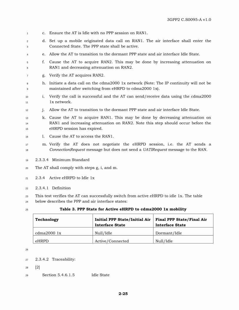
TRANSCRIPT
3GPP2 C.S0095-A
Version 1.0
Version Date: Sep 2013
Signaling Test Specification for EUTRAN-
cdma2000 Connectivity and Interworking
1
© 2013 3GPP2 3GPP2 and its Organizational Partners claim copyright in this document and individual Organizational Partners may copyright and issue documents or standards publications in individual Organizational Partner's name based on this document. Requests for reproduction of this document should be directed to the 3GPP2 Secretariat at [email protected]. Requests to reproduce individual Organizational Partner's documents should be directed to that Organizational Partner. See www.3gpp2.org for more information.

3GPP2 C.S0095-A v1.0
Revision History 1
Revision Description Of Changes Date
Rev 0 v1.0 Initial Publication December 2009
Rev 0 v2.0 Point Release for bug fixes July 2011
Rev A v1.0 Handoff with Pre-registration,eHRPD to
E-UTRAN Idle_Handoff,Maintain IP
context in Idle handoff. Registration on
CDMA1x via GCSNA. SMS via GCSNA.
Idle reselect to E-UTRAN from CDMA1x.
Sep 2013
3GPP2 C.S0095-A v1.0
CONTENTS
i
1 Introduction ............................................................................................................ 1-1 1
1.1 Scope ........................................................................................................... 1-1 2
1.2 Test Setup .................................................................................................... 1-1 3
2 Conformance and Interoperability Tests ................................................................... 2-1 4
2.1 Session Negotiation Tests .............................................................................. 2-1 5
2.1.1 Introduction ................................................................................................. 2-1 6
2.1.2 Session Negotiation with eHRPD Access Network ........................................... 2-1 7
2.1.3 Session Negotiation with HRPD Access Network ............................................ 2-2 8
2.1.4 ProtocolID 0x08 Negotiation during Session Establishment with eHRPD 9
Access Network ............................................................................................ 2-4 10
2.1.5 MMPA based eHRPD Personality Negotiation with eHRPD Access Network ..... 2-5 11
2.1.6 Switching between MMPA and EMPA based eHRPD Personality ..................... 2-7 12
2.2 Session Configuration Tests for Dormant Mobility between eHRPD and HRPD 2-9 13
2.2.1 Introduction ................................................................................................. 2-9 14
2.2.2 Dormant eHRPD to HRPD mobility with eHRPD to HRPD personality switch 15
occurring in response to ConnectionRequest ................................................. 2-9 16
2.2.3 Dormant eHRPD to HRPD mobility with eHRPD to HRPD personality switch 17
initiated in response to access..................................................................... 2-11 18
2.2.4 Dormant HRPD to eHRPD mobility with HRPD to eHRPD personality switch 19
occurring in response to ConnectionRequest ............................................... 2-12 20
2.2.5 Dormant HRPD to eHRPD mobility with HRPD to eHRPD personality switch 21
initiated in response to access..................................................................... 2-14 22
2.2.6 eHRPD to HRPD Dormant mobility with SCP renegotiation of ProtocolID 23
initiated at Access ....................................................................................... 2-16 24
2.2.7 HRPD to eHRPD Dormant mobility with SCP Renegotiation of ProtocolID 25
initiated at Access ....................................................................................... 2-19 26
2.2.8 Session Renegotiation when Session Transfer is Unsuccessful ..................... 2-21 27
2.3 cdma2000 1x and eHRPD Mobility .............................................................. 2-23 28
2.3.1 Introduction ............................................................................................... 2-23 29
2.3.2 Dormant 1x to eHRPD System Reselection .................................................. 2-23 30
2.3.3 Dormant eHRPD to 1x ................................................................................ 2-24 31
2.3.4 Active eHRPD to Idle 1x .............................................................................. 2-25 32
2.4 E-UTRA to eHRPD Handoff.......................................................................... 2-26 33
3GPP2 C.S0095-A v1.0
ii
2.4.1 Introduction ................................................................................................ 2-26 1
2.4.2 E-UTRAN Idle to eHRPD Dormant Handoff – Previous eHRPD Session, No 2
Pre-registration, A13-Session Information transfer available ......................... 2-26 3
2.4.3 E-UTRAN Idle to eHRPD Dormant Handoff – Previous eHRPD Session, No 4
Pre-registration, A13- Session Information transfer not available .................. 2-28 5
2.4.4 E-UTRAN Idle to eHRPD Dormant Handoff – With Pre-registration, Without 6
A13-Session Information transfer ................................................................ 2-29 7
2.4.5 Non-optimized Active E-UTRAN to eHRPD Idle – No Preregistration, 8
Connection Release with Redirection Indication ........................................... 2-30 9
2.4.6 Non-Optimized Active E-UTRAN to idle eHRPD System Selection – E-UTRAN 10
System Lost – No preregistration .................................................................. 2-32 11
2.5 eHRPD to Idle E-UTRAN Handoff ................................................................. 2-33 12
2.5.1 Introduction ................................................................................................ 2-33 13
2.5.2 Non-optimized Dormant eHRPD to Idle E-UTRAN System Reselection ........... 2-34 14
2.5.3 Non-optimized Dormant eHRPD to Idle E-UTRAN System Reselection-Non 15
BSR, Higher priority for E-UTRA .................................................................. 2-35 16
2.5.4 Non-optimized Dormant eHRPD to Idle E-UTRAN System Reselection-Non 17
BSR, Higher priority for eHRPD ................................................................... 2-37 18
2.5.5 Active eHRPD to E-UTRAN Handoff .............................................................. 2-38 19
2.5.6 Ping-ponging: Lost eHRPD and LTE, Partial HSGW context available, A13 20
available ..................................................................................................... 2-39 21
2.5.7 Ping-ponging: Lost eHRPD and LTE, Partial HSGW context available, A13 22
not available ............................................................................................... 2-41 23
2.5.8 Active eHRPD to E-UTRAN Handoff – failed redirection and another E-24
UTRAN available ......................................................................................... 2-42 25
2.5.9 Active eHRPD to E-UTRAN Handoff – failed redirection and no other E-26
UTRAN available ......................................................................................... 2-43 27
2.6 Registration and SMS in 1x CS Domain through E-UTRAN Tests for UE with 28
1T1R Configuration ................................................................................................... 2-45 29
2.6.1 Power up registration in 1x CS domain via GCSNA tunnel ............................ 2-45 30
2.6.2 Power Down registration in 1x CS domain via GCSNA tunnel ....................... 2-46 31
2.6.3 Timer base registration in 1x CS domain via GCSNA tunnel ......................... 2-47 32
2.6.4 Zone base registration by location area changed in 1x CS domain via 33
GCSNA tunnel ............................................................................................. 2-48 34
2.6.5 Send 1x SMS via GCSNA tunnel over E-UTRAN............................................ 2-49 35
2.6.6 Receive 1x receive 1x short message via GCSNA tunnel over E-UTRAN ......... 2-50 36
3GPP2 C.S0095-A v1.0
CONTENTS
iii
2.7 1x-E-UTRAN Idle reselection ....................................................................... 2-52 1
2.7.1 1x-EUTRAN Idle reselection when EUTRAN has higher Priority .................... 2-52 2
2.7.2 1x-EUTRAN Idle reselection when EUTRAN has equal or lower Priority ........ 2-53 3
2.7.3 1x-EUTRAN Idle reselection without the Priority field. .................................. 2-54 4
2.7.4 Determination of GCSNARevision ................................................................ 2-54 5
2.7.5 Determination of GCSNAOption .................................................................. 2-55 6
2.8 UE handle GCSNA message in LTE network. ............................................... 2-56 7
2.8.1 Introduction ............................................................................................... 2-56 8
2.8.2 Transmission and Reception of 1x messages ............................................... 2-56 9
2.9 PPP Based Main-Service Connection Establishment..................................... 2-57 10
2.9.1 Introduction ............................................................................................... 2-57 11
2.9.2 EAP AKA’ Authentication during Initial PPP session establishment .............. 2-58 12
2.9.3 EAP AKA’ Authentication Failure during Initial PPP session establishment 13
(Incorrect AUTN) ......................................................................................... 2-59 14
2.10 IP Address Assignment and PDN Attach and Detach Procedures .................. 2-60 15
2.10.1 Introduction ............................................................................................... 2-60 16
2.10.2 IPv4 address assignment through VSNCP .................................................... 2-60 17
2.10.3 IPv6 address assignment through VSNCP .................................................... 2-62 18
2.10.4 HSGW initiated PDN release through VSNCP ............................................... 2-63 19
2.10.5 Access Terminal initiated PDN release through VSNCP ................................ 2-64 20
2.10.6 Network Initiated PDN resynchronization VSNCP ......................................... 2-65 21
2.10.7 PPP Renegotiation upon Inter-HSGW handoff .............................................. 2-66 22
2.10.8 eHRPD loss and re-acquisition before expiration of PPP timer ...................... 2-68 23
2.10.9 Dual IP address (IPv4 and IPv6) assignment through VSNCP ....................... 2-69 24
2.10.10 UICC based APN connectivity ................................................................ 2-70 25
2.10.11 PDN Release based on Inactivity Timer .................................................. 2-71 26
2.10.12 PDN Application Blocking for Dual IP PDN ............................................. 2-72 27
2.11 PDN Multiplexing and QoS Establishment ................................................... 2-73 28
2.11.1 Introduction ............................................................................................... 2-73 29
2.11.2 PDN Multiplexing on the Main Service Connection over SO 59 ..................... 2-73 30
2.11.3 PDN Multiplexing on Auxiliary Service Connection over SO 72 ..................... 2-76 31
3GPP2 C.S0095-A v1.0
iv
2.11.4 QoS Establishment and PDN ID over SO 64 or SO 67 ................................... 2-78 1
2.11.5 QoS Establishment for Dual IP address (IPv4 and IPv6) assignment .............. 2-81 2
3 End to End Application Tests .................................................................................... 3-1 3
3.1 SMS origination and termination during active eHRPD session ....................... 3-1 4
3.1.1 Introduction .................................................................................................. 3-1 5
3.1.2 SMS origination during active eHRPD session ................................................ 3-1 6
3.1.3 SMS termination during active eHRPD session ............................................... 3-2 7
3.2 SMS origination and termination during dormant eHRPD session .................. 3-3 8
3.2.1 Introduction .................................................................................................. 3-3 9
3.2.2 SMS origination during dormant eHRPD session ............................................ 3-3 10
3.2.3 SMS termination during dormant eHRPD session .......................................... 3-4 11
3.3 Voice call origination and termination during active eHRPD session ............... 3-5 12
3.3.1 Introduction .................................................................................................. 3-5 13
3.3.2 Voice call origination during active eHRPD session ......................................... 3-5 14
3.3.3 Voice call termination during active eHRPD session ....................................... 3-6 15
3.4 Voice call origination and termination during dormant eHRPD session ........... 3-7 16
3.4.1 Introduction .................................................................................................. 3-7 17
3.4.2 Voice call origination during dormant eHRPD session .................................... 3-7 18
3.4.3 Voice call termination during dormant eHRPD session ................................... 3-8 19
20
21
3GPP2 C.S0095-A v1.0
v
Table of Figures 1
Figure 1 – Test Setup with two Radio Access Networks ................................................... 1-1 2
Figure 2 – Test Setup for mobility between E-UTRAN and eHRPD ................................... 1-2 3
Figure 3 - Test Setup for interworking of cdma2000® 1x with E-UTRAN ......................... 1-3 4
Figure 4 - Test Setup for interworking of cdma2000® 1x with E-UTRAN ......................... 1-3 5
6
7

3GPP2 C.S0095-A v1.0
vi
This page is intentionally left blank.1
3GPP2 C.S0095-A v1.0
vii
Table of Tables 1
Table 1. PPP State for cdma2000 1x to eHRPD mobility ................................................ 2-23 2
Table 2. PPP State for eHRPD to cdma2000 1x mobility ................................................ 2-24 3
Table 3. PPP State for Active eHRPD to cdma2000 1x mobility ...................................... 2-25 4
Table 4. State transition for Active E-UTRAN to eHRPD Handoff due to Redirection ....... 2-30 5
Table 5. State transition for Active E-UTRAN to eHRPD Handoff due to System Loss ..... 2-32 6
Table 6. State transition for Dormant eHRPD to E-UTRAN Handoff ............................... 2-34 7
Table 8. PPP State for Dormant eHRPD to E-UTRAN Handoff ........................................ 2-37 8
Table 9. State transition for active eHRPD to E-UTRAN handoff due to redirection ....... 2-38 9
Table 10. State transition for active eHRPD to E-UTRAN handoff due to redirection ..... 2-42 10
Table 11. State transition for active eHRPD to E-UTRAN handoff due to redirection ..... 2-44 11
Table 12. State for Power Up registration on CDMA1x network via GCSNA tunnel. ........ 2-45 12
Table 13. State for Power Down registration on CDMA1x network via GCSNA tunnel. ... 2-46 13
Table 14. State for Power Up registration on CDMA1x network via GCSNA tunnel. ........ 2-47 14
Table 15. State for Power Up registration on CDMA1x network via GCSNA tunnel. ........ 2-48 15
Table 16. State for Send 1x SMS on CDMA1x network via GCSNA tunnel. .................... 2-49 16
Table 17. State for Receive 1x receive 1x short message on CDMA1x network via GCSNA 17
tunnel. .................................................................................................................. 2-50 18
Table 18. State for receive 1x short message on CDMA1x network via GCSNA tunnel. ... 2-51 19
Table 19. State for 1x-E-UTRAN Idle reselection ........................................................... 2-52 20
Table 20. State for 1x-E-UTRAN Idle reselection ........................................................... 2-53 21
Table 21. State for 1x-E-UTRAN Idle reselection ........................................................... 2-54 22
Table 22. State for 1x-E-UTRAN Idle reselection ........................................................... 2-55 23
Table 23. State for receive 1x message via GCSNA tunnel. ............................................ 2-57 24
25
26

3GPP2 C.S0095-A v1.0
viii
This page is intentionally left blank.1
3GPP2 C.S0095-A v1.0
ix
FOREWORD 1
(This foreword is not part of this specification) 2
This specification was prepared by Technical Specification Group C of the Third Generation 3
Partnership Project 2 (3GPP2). This specification is the second version of the document and 4
provides the signaling conformance and interoperability requirements for C.S0087-0 5
(Interworking of cdma2000 1X High Rate Packet Data and Long Term Evolution Systems) 6
and X.S0057-0 (E-UTRAN - eHRPD Connectivity and Interworking: Core Network Aspects). 7
8
9

3GPP2 C.S0095-A v1.0
x
This page is intentionally left blank. 1
2
3GPP2 C.S0095-A v1.0
REFERENCES
1
This section provides references to other specifications and standards that are necessary to 1
implement this document. 2
3
The following standards contain provisions which, through reference in this text, constitute 4
provisions of this Standard. At the time of publication, the editions indicated were valid. All 5
standards are subject to revision, and parties to agreements based on this Standard are 6
encouraged to investigate the possibility of applying the most recent editions of the 7
standards indicated below. 8
1. 3GPP2: C.S0038-B v1.0, Signaling Conformance Specification for High Rate Packet 9
Data Air Interface. 10
2. 3GPP2: C.S0087-A v2.0, E-UTRAN – cdma2000 Connectivity and Interworking: Air 11
Interface Specification. 12
3. 3GPP2: X.S0057-B v1.0, E-UTRAN - eHRPD Connectivity and Interworking: Core 13
Network Aspects. 14
4. 3GPP2: C.S0015-B v2.0, Short Message Service (SMS) for Wideband Spread 15
Spectrum Systems. 16
5. 3GPP2: C.S0081-0 v1.0, Signaling Conformance Specification for cdma2000 High 17
Rate Packet Data Supplemental Services. 18
6. 3GPP2: C.S0024-B v3.0, cdma2000 High Rate Packet Data Air Interface 19
Specification. 20
7. 3GPP2: C.S0024-100-C v2.0, Introduction to cdma2000 High Rate Packet Data Air 21
Interface Specification. 22
8. 3GPP2: C.S0024-200-C v2.0, Physical Layer for cdma2000 High Rate Packet Data 23
Air Interface Specification 24
9. 3GPP2: C.S0024-300-C v2.0, Medium Access Control Layer for cdma2000 High 25
Rate Packet Data Air Interface Specification 26
10. 3GPP2: C.S0024-400-C v2.0, Connection and Security Layers for cdma2000 High 27
Rate Packet Data Air Interface Specification 28
11. 3GPP2: C.S0024-500-C v2.0, Application, Stream and Session Layers for 29
cdma2000 High Rate Packet Data Air Interface Specification 30
12. 3GPP2: C.S0063-B v1.0, cdma2000 High Rate Packet Data Supplemental Services. 31
13. 3GPP2: C.S0005-E v2.0, Upper Layer (Layer 3) Signaling Standard for cdma2000 32
Spread Spectrum Systems. 33
14. 3GPP: TS 36.331 Radio Resource Control; Protocol Specification (Release 8) 34
15. 3GPP2: A.S0008-C, v4.0, Interoperability Specification (IOS) for High Rate Packet 35
Data (HRPD) Radio Access Network Interfaces with Session Control in the Access 36
Network 37
16. 3GPP2: C.S0097-0, v2.0, E-UTRAN – cdma2000 1x Connectivity and Interworking 38
Air Interface Specification. 39

3GPP2 C.S0095-A v1.0
2
17. 3GPP: TS 23.401, General Packet Radio Service (GPRS) enhancements for Evolved 1
18 Universal Terrestrial Radio Access Network (E-UTRAN) access, (Release 9). 2
18. 3GPP: TS 23.272, Circuit Switched Fallback in Evolved Packet System; Stage 2 3
(Release A). 4
5
3GPP2 C.S0095-A v1.0
1-1
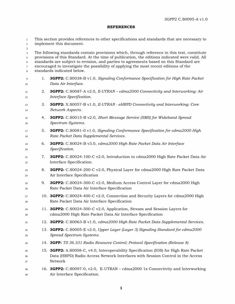
1 Introduction 1
1.1 Scope 2
This specification defines signaling conformance and interoperability tests for CDMA 3
infrastructure and mobile stations using eHRPD and interworking of eHRPD with HRPD, 4
cdma2000® 1x and E-UTRAN systems. 5
1.2 Test Setup 6
The typical test set-up required for the test is shown below. 7
MS/AT/UE
Under Test
Rx/Tx
Io
RAN 1
(eHRPD/
HRPD/
cdma2000 1x)
Tx
Rx
RAN 2
(eHRPD/
HRPD/
cdma2000 1x)
Tx
Rx
Ior1
Ior2 Ior2^
Ior1^
8
Figure 1 – Test Setup with two Radio Access Networks 9
10
11
12
cdma2000® is the trademark for the technical nomenclature for certain specifications 13
and standards of the Organizational Partners (OPs) of 3GPP2. Geographically (and as 14
of the date of publication), cdma2000® is a registered trademark of the 15
Telecommunications Industry Association (TIA-USA) in the United States. 16
17
3GPP2 C.S0095-A v1.0
1-2
MS/AT/UE
Under Test
Rx/Tx
Io
RAN 1
(eHRPD/
HRPD/
cdma2000 1x)
Tx
Rx
RAN 2
(eHRPD/
HRPD/
cdma2000 1x)
Tx
Rx
Ior1
Ior2 Ior2^
Ior1^
RAN 3
(E-UTRAN)
Ior3 Ior3Tx
Rx
^
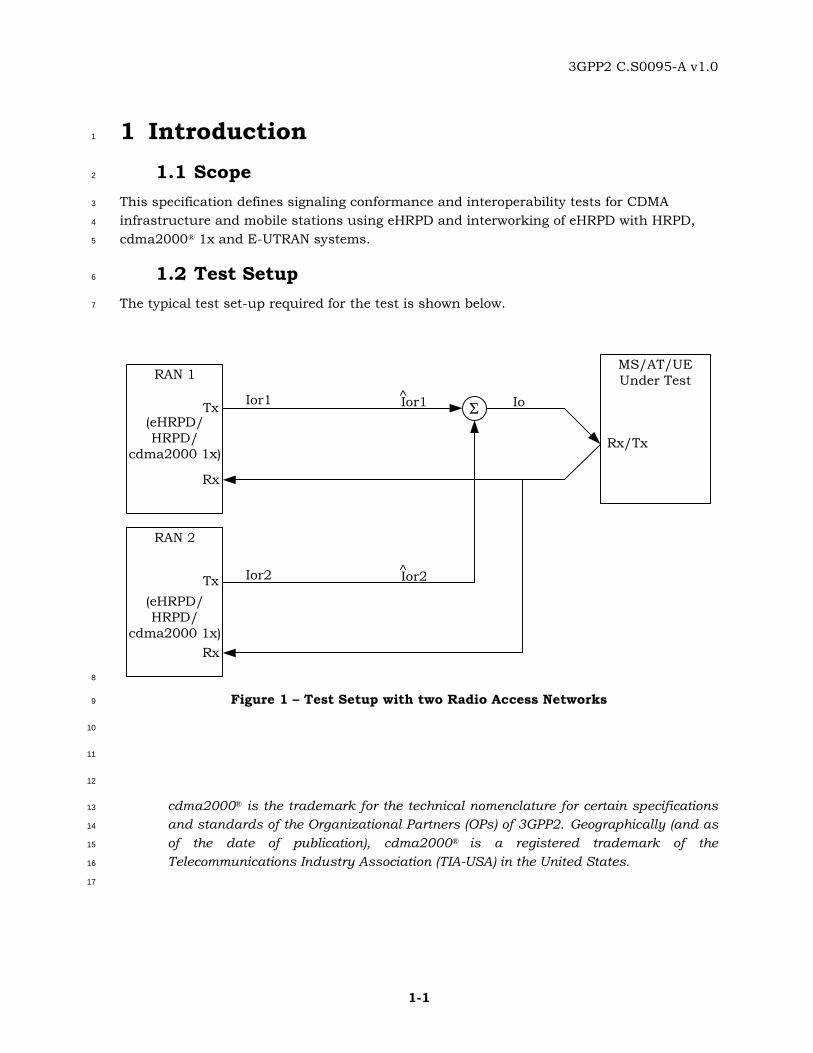
1
Figure 2 – Test Setup for mobility between E-UTRAN and eHRPD 2
3
4
3GPP2 C.S0095-A v1.0
1-3
MS/AT/UE
Under Test
Rx/Tx
Io
RAN 1
(cdma2000
1x)
Tx
Rx
RAN 2
(E-UTRAN)
Tx
Rx
Ior1
Ior2 Ior2^
Ior1^
RAN 3
(E-UTRAN)
Ior3 Ior3Tx
Rx
^
1
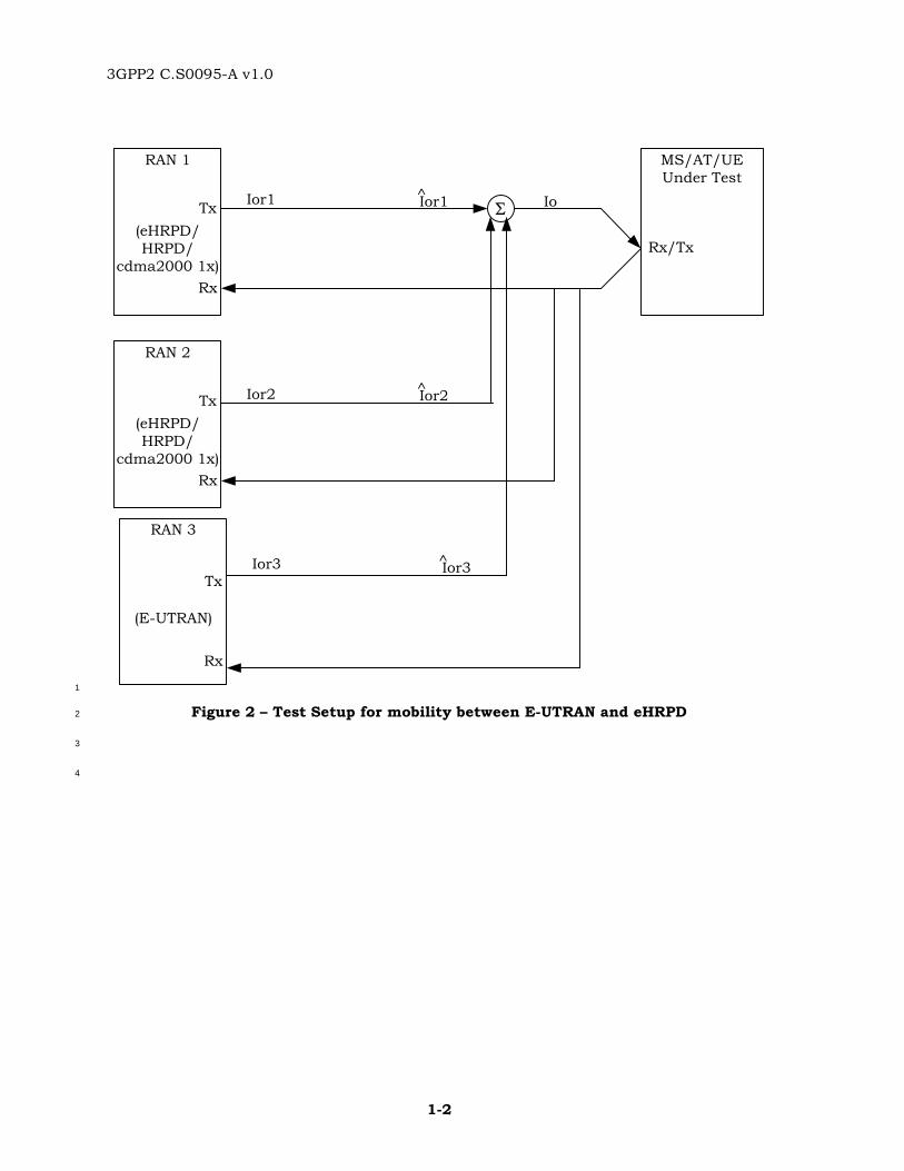
Figure 3 - Test Setup for interworking of cdma2000® 1x with E-UTRAN 2
MS/AT/UE
Under Test
Rx/Tx
Io
RAN 1
(E-UTRAN)
Tx
Rx
Ior1 Ior1^
3
Figure 4 - Test Setup for interworking of cdma2000® 1x with E-UTRAN 4
5

3GPP2 C.S0095-A v1.0
1-4
The page is intentionally left for blank. 1
2
3GPP2 C.S0095-A v1.0
2-1
2 Conformance and Interoperability Tests 1
2.1 Session Negotiation Tests 2
2.1.1 Introduction 3
Tests included in this section verify that the Access Terminal (AT) advertises its eHRPD 4
capability to the eHRPD network during session negotiation and accepts the protocols and 5
parameters to support eHRPD session. 6
2.1.2 Session Negotiation with eHRPD Access Network 7
2.1.2.1 Definition 8
This test verifies that the AT advertises eHRPD capability to the network during session 9
negotiation and that this capability is successfully negotiated between the access terminal 10
and the eHRPD network. 11
2.1.2.2 Traceability: 12
[2] 13
Section 2.3 Packet Application Negotiation 14
Section 3.1 Additional Requirement to support eHRPD operation in 15
Enhanced Multi-Flow Packet Application or Multi-Link Multi-16
Flow Packet Application 17
Section 3.2 Additional Requirements to support eHRPD operation in 18
Multi-Flow Packet Application 19
[6] 20
Section 6.2.6.1.2 Processing the SessionClose Message 21
[7] 22
Section 2.9.2.5 ATSupportedFlowProtocolParametersPP attribute 23
2.1.2.3 Test Procedure 24
a. Ensure that eHRPD system is available to the AT and E-UTRAN system is 25
unavailable to the AT. 26
b. If the AT has an open session with the RAN: 27
1. Instruct the RAN to send a SessionClose message to the AT. 28
2. Ensure that the AT sends a SessionClose message to the RAN. 29
c. Ensure that the AT has an eHRPD IMSI and credentials (authentication keys) 30
provisioned. 31
d. Cause the AT to negotiate a new session with the RAN. 32

3GPP2 C.S0095-A v1.0
2-2
e. Verify that the AT includes Application Subtypes Alternate EMPA (0xFFFE), DPA 1
(0x0002), MPA (0x0005), EMPA (0x0009), and optionally MMPA (0x000D) bound to 2
the service network for ATSupportedApplicationSubtype attribute in the 3
ConfigurationRequest message for SCP configuration. 4
f. Ensure that the RAN sends a ConfigurationResponse message in response to the 5
ConfigurationRequest message. 6
g. Verify that the AT does not propose Alternate EMPA bound to service network 7
(0xFFFE) in the ConfigurationRequest message for the stream protocol. 8
h. Verify that the AT proposes DPA (0x0002), MPA (0x0005), EMPA (0x0009), and 9
optionally MMPA (0x000D) bound to the service network in the ConfigurationRequest 10
message for the stream protocol. 11
i. Ensure that the RAN accepts the EMPA bound to service network (0x0009) in the 12
ConfigurationResponse message for the stream protocol. 13
j. Verify that the AT includes a value of 0x07 for the ProtocolSupported field in the 14
ATSupportedFlowProtocolParametersPP attribute of EMPA. 15
k. Ensure that the RAN proposes a value of 0x07 for the ProtocolID field of the 16
FlowNNFlowProtocolParametersFwd and FlowNNFlowProtocolParametersRev 17
attributes of the EMPA Link Flow bound to ReservationLabel 0xFF. 18
l. Verify that the AT accepts a value of 0x07 for the ProtocolID field of the 19
FlowNNFlowProtocolParametersFwd and FlowNNFlowProtocolParametersRev 20
attributes of the EMPA Link Flow bound to ReservationLabel 0xFF as proposed by 21
the RAN. 22
m. Verify that the AT is able to successfully complete the session negotiation. 23
n. Cause the AT to start a packet data call and establish a connection with the RAN. 24
o. Verify that the AT is able to successfully send and receive data using 25
ReservationLabel 0xFF. 26
2.1.2.4 Minimum Standard 27
The AT shall comply with steps e, g, h, j, l, m and o. 28
2.1.3 Session Negotiation with HRPD Access Network 29
2.1.3.1 Definition 30
This test verifies that the AT advertises eHRPD capability to the RAN during session 31
negotiation and that session negotiation proceeds when this capability is not negotiated by 32
the HRPD RAN. 33
2.1.3.2 Traceability: 34
[2] 35
Section 2.3 Packet Application Negotiation 36
3GPP2 C.S0095-A v1.0
2-3
Section 3.1 Additional Requirement to support eHRPD operation in 1
Enhanced Multi-Flow Packet Application or Multi-Link Multi-2
Flow Packet Application 3
Section 3.2 Additional Requirements to support eHRPD operation in 4
Multi-Flow Packet Application 5
[6] 6
Section 6.2.6.1.2 Processing the SessionClose Message 7
[7] 8
Section 2.9.2.5 ATSupportedFlowProtocolParametersPP attribute 9
2.1.3.3 Test Procedure 10
a. Ensure that HRPD system is available to the AT and E-UTRAN system is unavailable 11
to the AT. 12
b. If the AT has an open session with the RAN: 13
1. Instruct the RAN to send a SessionClose message to the AT. 14
2. Ensure that the AT sends a SessionClose message to the RAN. 15
c. Ensure that the AT has an eHRPD IMSI and credentials (authentication keys) 16
provisioned. 17
d. Cause the AT to negotiate a new session with the RAN. 18
e. Verify that the AT includes Application Subtypes Alternate EMPA (0xFFFE), DPA 19
(0x0002), MPA (0x0005), EMPA (0x0009), and optionally MMPA (0x000D) bound to 20
the service network for the ATSupportedApplicationSubtype attribute in the 21
ConfigurationRequest message for SCP configuration. 22
f. Ensure that the RAN sends a ConfigurationResponse message in response to the 23
ConfigurationRequest message. 24
g. Verify that the AT does not propose Alternate EMPA bound to service network 25
(0xFFFE) in the ConfigurationRequest message for the stream protocol. 26
h. Ensure that the RAN accepts any application subtype other than Alternate EMPA 27
bound to service network (0xFFFE) in the ConfigurationResponse message for the 28
stream protocol. Note, the default behavior of the RAN will always follow this step as 29
the AT should not propose Alternate EMPA in step g. 30
i. Ensure that the RAN does not propose a value of 0x07 or 0x08 for the ProtocolID 31
field of the FlowNNFlowProtocolParametersFwd and 32
FlowNNFlowProtocolParametersRev attributes of the Link Flow bound to 33
ReservationLabel 0xFF. 34
j. Verify that the AT is able to successfully complete the session negotiation. 35
k. Cause the AT to start a packet data call and establish a connection with the RAN. 36
3GPP2 C.S0095-A v1.0
2-4
l. Verify that the AT is able to successfully send and receive data using 1
ReservationLabel 0xFF. 2
2.1.3.4 Minimum Standard 3
The access terminal shall comply with steps e, g, j and l. 4
2.1.4 ProtocolID 0x08 Negotiation during Session Establishment with eHRPD Access 5
Network 6
2.1.4.1 Definition 7
This test verifies that if the AT supports ProtocolID value of 0x08, then the AT advertises 8
this capability during session establishment. Further, it also verifies that if the AN 9
negotiates ProtocolID value of 0x08 for the FlowNNFlowProtocolParametersRev attribute of 10
the link flow bound to ReservationLabel 0xFE, then the AT accepts this value and can send 11
data for ReservationLabel 0xFE using this link. The test also verifies that data for other 12
ReservationLabels other than 0xFF can be sent using the same link flow to which 13
ReservationLabel 0xFE is bound. This test is not mandatory for the ATs. 14
2.1.4.2 Traceability: 15
[2] 16
Section 2.3 Packet Application Negotiation 17
Section 3.1 Additional Requirement to support eHRPD operation in 18
Enhanced Multi-Flow Packet Application or Multi-Link Multi-19
Flow Packet Application 20
Section 3.2 Additional Requirements to support eHRPD operation in 21
Multi-Flow Packet Application 22
[6] 23
Section 6.2.6.1.2 Processing the SessionClose Message 24
[7] 25
Section 2.9.2.5 ATSupportedFlowProtocolParametersPP attribute 26
2.1.4.3 Test Procedure 27
a. Ensure that eHRPD system is available to the AT and E-UTRAN system is 28
unavailable to the AT. 29
b. If the AT has an open session with the RAN: 30
1. Instruct the RAN to send a SessionClose message to the AT. 31
2. Ensure that the AT sends a SessionClose message to the RAN. 32
c. Ensure that the AT has eHRPD IMSI and credentials (authentication keys) 33
provisioned. 34
d. Cause the AT to negotiate a new session with the RAN. 35
3GPP2 C.S0095-A v1.0
2-5
e. Verify that the AT includes Application Subtypes Alternate EMPA (0xFFFE), DPA 1
(0x0002), MPA (0x0005), EMPA (0x0009), and optionally MMPA (0x000D) bound to 2
the service network for ATSupportedApplicationSubtype attribute in the 3
ConfigurationRequest message for SCP configuration. 4
f. Ensure that the RAN sends a ConfigurationResponse message in response to the 5
ConfigurationRequest message. 6
g. Verify that the AT does not propose Alternate EMPA bound to service network 7
(0xFFFE) in the ConfigurationRequest message for the stream protocol. 8
h. Verify that the AT proposes DPA (0x0002), MPA (0x0005), EMPA (0x0009), and 9
optionally MMPA (0x000D) bound to the service network in the ConfigurationRequest 10
message for the stream protocol. 11
i. Ensure that the RAN accepts the EMPA bound to service network (0x0009) in the 12
ConfigurationResponse message for the stream protocol. 13
j. Verify that the AT includes a value of 0x07 and 0x08 for the ProtocolSupported field 14
in the ATSupportedFlowProtocolParametersPP attribute of EMPA. 15
k. Ensure that the RAN proposes the a value of 0x08 for the ProtocolID field of the 16
FlowNNFlowProtocolParametersFwd and FlowNNFlowProtocolParametersRev 17
attributes of the EMPA Link Flow bound to ReservationLabel 0xFE. Ensure that the 18
link flow is active. 19
l. Instruct the AN to map ReservationLabel other than 0xFF to the same link flow to 20
which ReservationLabel 0xFE is mapped. 21
m. Verify that the AT accepts the value of 0x08 for the ProtocolID field of the 22
FlowNNFlowProtocolParametersFwd and FlowNNFlowProtocolParametersRev 23
attributes of the EMPA Link Flow bound to ReservationLabel 0xFE as proposed by 24
the RAN. 25
n. Verify that the AT is able to successfully complete the session negotiation. 26
o. Cause the AT to start a packet data call and establish a connection with the RAN. 27
p. Verify that the AT is able to successfully send and receive data for ReservationLabel 28
0xFE. 29
2.1.4.4 Minimum Standard 30
The AT shall comply with steps e, g, h, j, m, n, and p. 31
2.1.5 MMPA based eHRPD Personality Negotiation with eHRPD Access Network 32
2.1.5.1 Definition 33
This test is only applicable to ATs that support MMPA based eHRPD operation. The test 34
verifies that the AT accepts personalities based on MMPA packet application. 35
3GPP2 C.S0095-A v1.0
2-6
2.1.5.2 Traceability: 1
[2] 2
Section 2.3 Packet Application Negotiation 3
Section 3.1 Additional Requirement to support eHRPD operation in 4
Enhanced Multi-Flow Packet Application or Multi-Link Multi-5
Flow Packet Application 6
Section 3.2 Additional Requirements to support eHRPD operation in 7
Multi-Flow Packet Application 8
[6] 9
Section 6.2.6.1.2 Processing the SessionClose Message 10
[7] 11
Section 2.9.2.5 ATSupportedFlowProtocolParametersPP attribute 12
2.1.5.3 Test Procedure 13
a. Ensure that eHRPD system is available to the AT and E-UTRAN system is 14
unavailable to the AT. 15
b. If the AT has an open session with the RAN: 16
1. Instruct the RAN to send a SessionClose message to the AT. 17
2. Ensure that the AT sends a SessionClose message to the RAN. 18
c. Ensure that the AT has eHRPD IMSI and credentials (authentication keys) 19
provisioned. 20
d. Cause the AT to negotiate a new session with the RAN. 21
e. Verify that the AT includes Application Subtypes Alternate EMPA (0xFFFE), 22
Alternate MMPA (0xFFFC), DPA (0x0002), MPA (0x0005), EMPA (0x0009), and 23
MMPA (0x000D) bound to the service network for ATSupportedApplicationSubtype 24
attribute in the ConfigurationRequest message for SCP configuration. 25
f. Ensure that the RAN sends a ConfigurationResponse message in response to the 26
ConfigurationRequest message. 27
g. Verify that the AT includes MMPA bound to the service network (0x000D) in the 28
proposed application subtypes in the ConfigurationRequest message for the stream 29
protocol and excludes Alternate MMPA bound to service network (0xFFFC) in the 30
proposed application subtypes in the ConfigurationRequest message for the stream 31
protocol. 32
h. Instruct the RAN to accept MMPA bound to service network (0x000D) in the 33
ConfigurationResponse message for the stream protocol. 34
i. Verify that the AT includes a value of 0x07 for the ProtocolSupported field in the 35
ATSupportedFlowProtocolParametersPP attribute of MMPA. 36
3GPP2 C.S0095-A v1.0
2-7
j. Ensure that the RAN proposes the a value of 0x07 for the ProtocolID field of the 1
FlowNNFlowProtocolParametersFwd and FlowNNFlowProtocolParametersRev 2
attributes of the MMPA Link Flow bound to ReservationLabel 0xFF. 3
k. Verify that the AT accepts the value of 0x07 for the ProtocolID field of the 4
FlowNNFlowProtocolParametersFwd and FlowNNFlowProtocolParametersRev 5
attributes of the MMPA Link Flow bound to ReservationLabel 0xFF as proposed by 6
the RAN. 7
l. Verify that the AT is able to successfully complete the session negotiation. 8
m. Cause the AT to start a packet data call and establish a connection with the RAN. 9
n. Verify that the AT is able to successfully send and receive data using 10
ReservationLabel 0xFF. 11
2.1.5.4 Minimum Standard 12
The AT shall comply with steps e, g, i, k, and n. 13
2.1.6 Switching between MMPA and EMPA based eHRPD Personality 14
2.1.6.1 Definition 15
This test is only applicable to ATs that support MMPA based eHRPD operation. The test 16
verifies that the AT is able to switch between EMPA and MMPA based eHRPD personality. 17
2.1.6.2 Traceability: 18
[2] 19
Section 2.3 Packet Application Negotiation 20
Section 3.1 Additional Requirement to support eHRPD operation in 21
Enhanced Multi-Flow Packet Application or Multi-Link Multi-22
Flow Packet Application 23
Section 3.2 Additional Requirements to support eHRPD operation in 24
Multi-Flow Packet Application 25
[6] 26
Section 6.2.6.1.2 Processing the SessionClose Message 27
[7] 28
Section 2.9.2.5 ATSupportedFlowProtocolParametersPP attribute 29
2.1.6.3 Test Procedure 30
a. Ensure that eHRPD system is available to the AT and E-UTRAN system is 31
unavailable to the AT. 32
b. If the AT has an open session with the RAN: 33
1. Instruct the RAN to send a SessionClose message to the AT. 34
3GPP2 C.S0095-A v1.0
2-8
2. Ensure that the AT sends a SessionClose message to the AN. 1
c. Ensure that the AT has eHRPD IMSI and credentials (authentication keys) 2
provisioned. 3
d. Cause the AT to negotiate a new session with the RAN. 4
e. Ensure that the AT includes Application Subtypes Alternate EMPA (0xFFFE), 5
Alternate MMPA (0xFFFC), DPA (0x0002), MPA (0x0005), EMPA (0x0009), and 6
MMPA (0x000D) bound to the service network for ATSupportedApplicationSubtype 7
attribute in the ConfigurationRequest message for SCP configuration. 8
f. Ensure that the RAN sends a ConfigurationResponse message in response to the 9
ConfigurationRequest message. 10
g. Verify that the AT includes EMPA bound to the service network (0x0009) in the 11
proposed application subtypes in the ConfigurationRequest message for the stream 12
protocol and excludes Alternate EMPA bound to service network (0xFFFE) in the 13
proposed application subtypes in the ConfigurationRequest message for the stream 14
protocol. 15
h. Instruct the RAN to accept EMPA bound to service network (0x0009) in the 16
ConfigurationResponse message for the stream protocol. 17
o. Verify that the AT includes a value of 0x07 for the ProtocolSupported field in the 18
ATSupportedFlowProtocolParametersPP attribute of EMPA. 19
p. Ensure that the RAN proposes the a value of 0x07 for the ProtocolID field of the 20
FlowNNFlowProtocolParametersFwd and FlowNNFlowProtocolParametersRev 21
attributes of the EMPA Link Flow bound to ReservationLabel 0xFF. 22
i. Verify that the AT sends a ConfigurationResponse message and accepts the value of 23
0x07 for the ProtocolID field of the FlowNNFlowProtocolParametersFwd and 24
FlowNNFlowProtocolParametersRev attributes of the EMPA Link Flow bound to 25
ReservationLabel 0xFF as proposed by the RAN. 26
j. After the AT responds to the RAN initiated ConfigurationRequest messages, instruct 27
the AN to send a SoftConfiguratonComplete message with Continue field set to ‘1’. 28
k. Verify that the AT includes MMPA bound to the service network (0x000D) in the 29
proposed application subtypes in the ConfigurationRequest message for the stream 30
protocol and excludes Alternate MMPA bound to service network (0xFFFC) in the 31
proposed application subtypes in the ConfigurationRequest message for the stream 32
protocol. 33
l. Instruct the RAN to accept MMPA bound to service network (0x000D) in the 34
ConfigurationResponse message for the stream protocol. 35
m. Verify that the AT includes a value of 0x07 for the ProtocolSupported field in the 36
ATSupportedFlowProtocolParametersPP attribute of MMPA. 37
n. Instruct the RAN to accept MMPA bound to service network (0x000D) in the 38
ConfigurationResponse message for the stream protocol for this personality. 39

3GPP2 C.S0095-A v1.0
2-9
o. Verify that the AT sends a ConfigurationResponse message and accepts the value of 1
0x07 for the ProtocolID field of the FlowNNFlowProtocolParametersFwd and 2
FlowNNFlowProtocolParametersRev attributes of the MMPA Link Flow bound to 3
ReservationLabel 0xFF as proposed by the RAN. 4
p. Ensure that the RAN sends a SoftConfiguratonComplete message with Continue field 5
set to ‘0’ and that EMPA based personality is in use. 6
q. Cause the AT to start a packet data call and establish a connection with the RAN. 7
r. Verify that the AT is able to send and receive data using ReservationLabel 0xFF. 8
s. Instruct the RAN to switch the personality of the AT from EMPA to MMPA based 9
personality. 10
t. Repeat steps q-r. 11
2.1.6.4 Minimum Standard 12
The AT shall comply with steps g, o, i, k, m, o, and r. 13
2.2 Session Configuration Tests for Dormant Mobility 14
between eHRPD and HRPD 15
2.2.1 Introduction 16
Tests included in this section verify that when the AT moves across eHRPD and HRPD RAN 17
boundary, the AT and the RAN negotiate attributes needed for operation in target eHRPD or 18
HRPD RAN. Note, IP continuity will not be maintained during mobility between eHRPD and 19
HRPD networks. 20
2.2.2 Dormant eHRPD to HRPD mobility with eHRPD to HRPD personality switch 21
occurring in response to ConnectionRequest 22
2.2.2.1 Definition 23
This test verifies that the AT is able to switch between eHRPD and HRPD capable 24
personalities. Specifically, it is verified that the AT switches to the HRPD personality when 25
the HRPD network switches the personality upon receiving a ConnectionRequest message 26
from the AT. The PPP renegotiation and the QoS related changes for this scenario will be 27
tested separately. 28
2.2.2.2 Traceability: 29
[2] 30
Section 2.3 Packet Application Negotiation 31
Section 3.1 Additional Requirement to support eHRPD operation in 32
Enhanced Multi-Flow Packet Application or Multi-Link Multi-33
Flow Packet Application 34
Section 3.2 Additional Requirements to support eHRPD operation in 35
3GPP2 C.S0095-A v1.0
2-10
Multi-Flow Packet Application 1
[6] 2
Section 6.2.6.1.2 Processing the SessionClose Message 3
[7] 4
Section 2.9.2.5 ATSupportedFlowProtocolParametersPP attribute 5
[1] 6
Section 6.3.2.3 Multiple Personality Negotiation 7
2.2.2.3 Test Procedure 8
a. Connect the AT as shown in Figure 1. Ensure that the eHRPD system is available to 9
the AT and HRPD system is unavailable to the AT. It is recommended that HRPD 10
and eHRPD RANs are configured to be in different subnets. 11
b. If the AT has an open session with the RAN: 12
1. Instruct the RAN to send a SessionClose message to the AT. 13
2. Ensure that the AT sends a SessionClose message to the RAN. 14
c. Cause the AT to negotiate a new session with the AN. 15
d. Ensure that the RAN negotiates two personalities for HRPD and eHRPD operation 16
and that the AT is operating with the eHRPD personality. Note, the RAN should use 17
separate packet applications for the two personalities. 18
e. Ensure that the AT is dormant on the eHRPD network. 19
f. Cause the pilot strength of the HRPD network to increase such that the AT is idle on 20
the HRPD network. 21
g. If the HRPD and eHRPD RANs are in different subnets: 22
1. Ensure that the AT sends a UATIRequest message and the RAN sends a 23
UATIAssignment message. 24
2. Ensure that the AT sends a UATIComplete message to the RAN. 25
h. Cause the AT to start a packet data call and send a ConnectionRequest message to 26
the HRPD RAN. 27
i. Instruct the HRPD network to send an AttributeUpdateRequest message changing 28
the SessionConfigurationToken with four MSB to the HRPD personality along with a 29
TrafficChannelAssignment message. Note, the RAN should include the 30
AttributeUpdateRequest message before the TrafficChannelAssignment message in 31
the same security layer packet. 32
j. Verify that the AT starts using the HRPD personality, i.e. in the MAC layer header 33
the AT uses a SessionConfigurationToken with four MSB equal to the four most 34
significant bits of SessionConfigurationToken for the HRPD personality, and that the 35
AT can send and receive data using ReservationLabel 0xFF. 36
3GPP2 C.S0095-A v1.0
2-11
2.2.2.4 Minimum Standard 1
The AT shall comply with step j. 2
2.2.3 Dormant eHRPD to HRPD mobility with eHRPD to HRPD personality switch initiated 3
in response to access 4
2.2.3.1 Definition 5
This test verifies that the AT is able to switch between eHRPD and HRPD capable 6
personalities during eHRPD to HRPD mobility. Specifically, it is verified that the AT 7
switches to the HRPD personality when the HRPD network switches the personality along 8
with the UATIAssignment message or in response to any other message sent by the AT on 9
the access channel. The PPP renegotiation and the QoS related changes for this scenario 10
will be tested separately. 11
2.2.3.2 Traceability: 12
[2] 13
Section 2.3 Packet Application Negotiation 14
Section 3.1 Additional Requirement to support eHRPD operation in 15
Enhanced Multi-Flow Packet Application or Multi-Link Multi-16
Flow Packet Application 17
Section 3.2 Additional Requirements to support eHRPD operation in 18
Multi-Flow Packet Application 19
[6] 20
Section 6.2.6.1.2 Processing the SessionClose Message 21
[7] 22
Section 2.9.2.5 ATSupportedFlowProtocolParametersPP attribute 23
[1] 24
Section 6.3.2.3 Multiple Personality Negotiation 25
2.2.3.3 Test Procedure 26
a. Connect the AT as shown in Figure 1. Ensure that the eHRPD system is available to 27
the AT and HRPD system is unavailable to the AT. It is recommended that HRPD 28
and eHRPD RANs are configured to be in different subnets. Note, this configuration 29
is useful in step g where it is required that the AT send a message on the access 30
channel. 31
b. If the AT has an open session with the AN: 32
1. Instruct the RAN to send a SessionClose message to the AT. 33
2. Ensure that the AT sends a SessionClose message to the RAN. 34
c. Cause the AT to negotiate a new session with the RAN. 35
3GPP2 C.S0095-A v1.0
2-12
d. Ensure that the RAN negotiates two personalities for HRPD and eHRPD operation 1
and that the AT is operating with the eHRPD personality. Note, the RAN should use 2
separate packet applications for the two personalities. 3
e. Ensure that the AT is dormant on the eHRPD network. 4
f. Cause the pilot strength of the HRPD network to increase such that the AT is idle on 5
the HRPD network. 6
g. Cause the AT to send a message on the access channel. For example, the AT may 7
send a UATIRequest message. 8
h. Instruct the HRPD network to send an AttributeUpdateRequest changing the 9
SessionConfigurationToken with four MSB to the HRPD personality. 10
i. Cause the AT to start a packet data call and establish a connection with the HRPD 11
RAN. 12
j. Verify that the AT starts using the HRPD personality, i.e. in the MAC layer header 13
the AT uses a SessionConfigurationToken with four MSB equal to the four most 14
significant bits of the SessionConfigurationToken for the HRPD personality, and that 15
the AT can send and receive data using ReservationLabel 0xFF. 16
2.2.3.4 Minimum Standard 17
The AT shall comply with step j. 18
2.2.4 Dormant HRPD to eHRPD mobility with HRPD to eHRPD personality switch 19
occurring in response to ConnectionRequest 20
2.2.4.1 Definition 21
This test verifies that the AT is able to switch between HRPD and eHRPD capable 22
personalities. Specifically, it is verified that the AT switches to the eHRPD personality when 23
the eHRPD network switches the personality upon receiving a ConnectionRequest message 24
from the AT after the UATIAssignment has been made. The test assumes that the RAN is 25
able to store the eHRPD capability of the AT and that this capability is part of session 26
transfer during mobility across eHRPD and HRPD. The PPP renegotiation and the QoS 27
related changes for this scenario will be tested separately. 28
Note, in the test procedure below, eHRPD and HRPD personalities are first negotiated in an 29
eHRPD network in steps a-e. This is followed by an eHRPD to HRPD dormant mobility in 30
steps f-k. These steps are necessary as it is assumed that the HRPD network may not be 31
capable of negotiating an eHRPD personality. 32
2.2.4.2 Traceability: 33
[2] 34
Section 2.3 Packet Application Negotiation 35
Section 3.1 Additional Requirement to support eHRPD operation in 36
Enhanced Multi-Flow Packet Application or Multi-Link Multi-37
3GPP2 C.S0095-A v1.0
2-13
Flow Packet Application 1
Section 3.2 Additional Requirements to support eHRPD operation in 2
Multi-Flow Packet Application 3
[6] 4
Section 6.2.6.1.2 Processing the SessionClose Message 5
[7] 6
Section 2.9.2.5 ATSupportedFlowProtocolParametersPP attribute 7
[1] 8
Section 6.3.2.3 Multiple Personality Negotiation 9
2.2.4.3 Test Procedure 10
a. Connect the AT as shown in Figure 1. Ensure that the eHRPD system is available to 11
the AT and HRPD system is unavailable to the AT. It is recommended that HRPD 12
and eHRPD RANs are configured to be in different subnets. 13
b. If the AT has an open session with the RAN: 14
1. Instruct the RAN to send a SessionClose message to the AT. 15
2. Ensure that the AT sends a SessionClose message to the RAN. 16
c. Cause the AT to negotiate a new session with the AN. 17
d. Ensure that the RAN negotiates two personalities for HRPD and eHRPD operation 18
and that the AT is operating with the eHRPD personality. Note, the RAN should use 19
separate packet applications for the two personalities. 20
e. Ensure that the AT is dormant on the eHRPD network. 21
f. Cause the pilot strength of the HRPD network to increase such that the AT is idle on 22
the HRPD network. 23
g. If the HRPD and eHRPD RANs are in different subnets: 24
1. Ensure that the AT sends a UATIRequest message and the RAN sends a 25
UATIAssignment message. 26
2. Ensure that the AT sends a UATIComplete message to the RAN. 27
h. Cause the AT to start a packet data call and send a ConnectionRequest message to 28
the HRPD RAN. 29
i. Instruct the HRPD network to send an AttributeUpdateRequest message changing 30
the SessionConfigurationToken with four MSB to the HRPD personality along with a 31
TrafficChannelAssignment message. Note, the AN should include the 32
AttributeUpdateRequest message before the TrafficChannelAssignment message in 33
the same security layer packet. 34
j. Ensure that the AT starts using the HRPD personality, i.e. in the MAC layer header 35
the AT uses a SessionConfigurationToken with four MSB equal to the four most 36
3GPP2 C.S0095-A v1.0
2-14
significant bits of SessionConfigurationToken for the HRPD personality, and that the 1
AT can send and receive data using ReservationLabel 0xFF. 2
k. Allow the AT to become dormant on the HRPD network. 3
l. Cause the pilot strength of the eHRPD network to increase such that the AT is idle 4
on the eHRPD network. 5
m. If the HRPD and eHRPD RANs are in different subnets: 6
1. Ensure that the AT sends a UATIRequest message and the RAN sends a 7
UATIAssignment message. 8
2. Ensure that the AT sends a UATIComplete message to the RAN. 9
n. Cause the AT to send a ConnectionRequest message to the eHRPD RAN. 10
o. Instruct the eHRPD network to send an AttributeUpdateRequest message changing 11
the SessionConfigurationToken with four MSB to the eHRPD personality along with 12
a TrafficChannelAssignment message. Note, the RAN should include the 13
AttributeUpdateRequest message before the TrafficChannelAssignment message in 14
the same security layer packet. 15
p. Ensure that the AT performs EAP AKA’ Authentication as specified in section 2.9.2 16
and obtains an IP address as specified in section 2.10.2 or 2.10.3. 17
q. Verify that the AT starts using the eHRPD personality, i.e. in the MAC layer header 18
the AT uses a SessionConfigurationToken with four MSB equal to the four most 19
significant bits of SessionConfigurationToken for the eHRPD personality, and that 20
the AT can send and receive data using ReservationLabel 0xFF that is bound to the 21
EMPA Link Flow with the ProtocolID field of the FlowNNFlowProtocolParametersFwd 22
and FlowNNFlowProtocolParametersRev attributes negotiated to a value 0x07. 23
2.2.4.4 Minimum Standard 24
The AT shall comply with step q. 25
2.2.5 Dormant HRPD to eHRPD mobility with HRPD to eHRPD personality switch initiated 26
in response to access 27
2.2.5.1 Definition 28
This test verifies that the AT is able to switch between HRPD and eHRPD capable 29
personalities. Specifically, it is verified that the AT switches to the eHRPD personality when 30
the eHRPD network switches the personality along with the UATIAssignment message or in 31
response to any other message sent by the AT on the access channel. The test assumes 32
that the RAN is able to store the eHRPD capability of the AT and that this capability is part 33
of session transfer during mobility across eHRPD and HRPD. The PPP renegotiation and the 34
QoS related changes for this scenario will be tested separately. 35
Note, in the test procedure below, eHRPD and HRPD personalities are first negotiated in an 36
eHRPD network in steps a-e. This is followed by an eHRPD to HRPD dormant mobility in 37
steps f-k. These steps are necessary as it is assumed that the HRPD network may not be 38
3GPP2 C.S0095-A v1.0
2-15
capable of negotiating an eHRPD personality. 1
2.2.5.2 Traceability: 2
[2] 3
Section 2.3 Packet Application Negotiation 4
Section 3.1 Additional Requirement to support eHRPD operation in 5
Enhanced Multi-Flow Packet Application or Multi-Link Multi-6
Flow Packet Application 7
Section 3.2 Additional Requirements to support eHRPD operation in 8
Multi-Flow Packet Application 9
[6] 10
Section 6.2.6.1.2 Processing the SessionClose Message 11
[7] 12
Section 2.9.2.5 ATSupportedFlowProtocolParametersPP attribute 13
[1] 14
Section 6.3.2.3 Multiple Personality Negotiation 15
2.2.5.3 Test Procedure 16
a. Connect the AT as shown in Figure 1. Ensure that the eHRPD system is available to 17
the AT and HRPD system is unavailable to the AT. It is recommended that HRPD 18
and eHRPD RANs are configured to be in different subnets. 19
b. If the AT has an open session with the RAN: 20
1. Instruct the RAN to send a SessionClose message to the AT. 21
2. Ensure that the AT sends a SessionClose message to the RAN. 22
c. Cause the AT to negotiate a new session with the RAN. 23
d. Ensure that the RAN negotiates two personalities for HRPD and eHRPD operation 24
and that the AT is operating with the eHRPD personality. Note, the RAN should use 25
separate packet applications for the two personalities. 26
e. Ensure that the AT is dormant on the eHRPD network. 27
f. Cause the pilot strength of the HRPD network to increase such that the AT is idle on 28
the HRPD network. 29
g. If the HRPD and eHRPD RANs are in different subnets: 30
1. Ensure that the AT sends a UATIRequest message and the RAN sends a 31
UATIAssignment message. 32
2. Ensure that the AT sends a UATIComplete message to the AN. 33
3GPP2 C.S0095-A v1.0
2-16
h. Cause the AT to start a packet data call and send a ConnectionRequest message to 1
the HRPD RAN. 2
i. Instruct the HRPD network to send an AttributeUpdateRequest message changing 3
the SessionConfigurationToken with four MSB to the HRPD personality along with a 4
TrafficChannelAssignment message. Note, the RAN should include the 5
AttributeUpdateRequest message before the TrafficChannelAssignment message in 6
the same security layer packet. 7
j. Ensure that the AT starts using the HRPD personality, i.e. in the MAC layer header 8
the AT uses a SessionConfigurationToken with four MSB equal to the four most 9
significant bits of SessionConfigurationToken for the HRPD personality, and that the 10
AT can send and receive data using ReservationLabel 0xFF. 11
k. Allow the AT to become dormant on the HRPD network. 12
l. Cause the pilot strength of the eHRPD network to increase such that the AT is idle 13
on the eHRPD network. 14
m. Cause the AT to send a message on the access channel. For example, the AT may 15
send a UATIRequest message. 16
n. Instruct the eHRPD network to send an AttributeUpdateRequest changing the 17
SessionConfigurationToken with four MSB to the eHRPD personality. 18
o. Cause the AT to start a packet data call and to open a connection with the RAN and 19
send and receive data. 20
p. Ensure that the AT performs EAP AKA’ Authentication as specified in section 2.9.2 21
and obtains an IP address as specified in section 2.10.2 or 2.10.3. 22
q. Verify that the AT starts using the eHRPD personality, i.e. in the MAC layer header 23
the AT uses a SessionConfigurationToken with four MSB equal to the four most 24
significant bits of SessionConfigurationToken for the eHRPD personality, and that 25
the AT can send and receive data using ReservationLabel 0xFF that is bound to a 26
Link Flow with FlowNNFlowProtocolParametersFwd and 27
FlowNNFlowProtocolParametersRev attributes negotiated to a value of 0x07. 28
2.2.5.4 Minimum Standard 29
The AT shall comply with step q. 30
2.2.6 eHRPD to HRPD Dormant mobility with SCP renegotiation of ProtocolID initiated at 31
Access 32
2.2.6.1 Definition 33
This test verifies the AT’s support for negotiating ProtocolID through SCP based negotiation 34
for dormant mobility from eHRPD to HRPD. The test assumes that the session transfer can 35
occur through the A13 link between the HRPD and eHRPD RANs. 36
3GPP2 C.S0095-A v1.0
2-17
2.2.6.2 Traceability: 1
[2] 2
Section 2.3 Packet Application Negotiation 3
Section 3.1 Additional Requirement to support eHRPD operation in 4
Enhanced Multi-Flow Packet Application or Multi-Link Multi-5
Flow Packet Application 6
Section 3.2 Additional Requirements to support eHRPD operation in 7
Multi-Flow Packet Application 8
[6] 9
Section 6.2.6.1.2 Processing the SessionClose Message 10
Section 4.4.4.4.16 AttributeUpdateRequest Message 11
[7] 12
Section 2.5.4.1 Procedures 13
Section 2.9.2.5 ATSupportedFlowProtocolParametersPP attribute 14
[1] 15
Section 6.3.2.3 Multiple Personality Negotiation 16
2.2.6.3 Test Procedure 17
a. Connect the AT as shown in Figure 1. Ensure that the eHRPD system is available to 18
the AT and HRPD system is unavailable to the AT. It is recommended that HRPD 19
and eHRPD RANs are configured to be in different subnets. 20
b. If the AT has an open session with the AN: 21
1. Instruct the RAN to send a SessionClose message to the AT. 22
2. Ensure that the AT sends a SessionClose message to the RAN. 23
c. Cause the AT to negotiate a new session with the RAN. 24
d. Ensure that the RAN negotiates and AT accepts a value of 0x07 for the ProtocolID 25
field of the FlowNNFlowProtocolParametersFwd and 26
FlowNNFlowProtocolParametersRev attributes for the EMPA Link Flow bound to 27
ReservationLabel 0xFF. 28
e. Ensure that the AT can send and receive data using ReservationLabel 0xFF. 29
f. Ensure that the AT is dormant on the eHRPD network. 30
g. Cause the pilot strength of the HRPD network to increase such that the AT is idle on 31
the HRPD network. 32
h. If the HRPD and eHRPD ANs are in different subnets: 33
1. Ensure that the AT sends a UATIRequest message and the RAN sends a 34
UATIAssignment message. 35
3GPP2 C.S0095-A v1.0
2-18
2. Ensure that the AT sends a UATIComplete message to the RAN. 1
i. If the HRPD and eHRPD RANs are in different subnets cause the AT to send a 2
ConnectionRequest message to the HRPD RAN. 3
j. Instruct the RAN to send a ConfigurationStart message to the AT. 4
k. Verify that the AT sends a ConfigurationComplete or ConfigurationRequest message 5
to the RAN. 6
l. If the AT sends a ConfigurationRequest message to the RAN, ensure that the RAN 7
sends a ConfigurationResponse message and accepts the values proposed in the 8
ConfigurationRequest message. 9
m. During the AN initiated session configuration phase ensure that the RAN does not 10
propose a value of 0x07 or 0x08 for the ProtocolID field of the 11
FlowNNFlowProtocolParametersFwd and FlowNNFlowProtocolParametersRev 12
attributes of the Link Flow bound to ReservationLabel 0xFF. 13
n. Verify that the AT accepts the values proposed by the RAN and sends a 14
ConfigurationResponse message in response to the ConfigurationRequest message 15
sent by the RAN. 16
o. Instruct the RAN to send a ConfigurationComplete message to the AT. If the RAN 17
does not negotiate additional personality, ensure that the RAN sends the 18
ConfigurationComplete message with PersonalityIndexStore field set to a value that 19
overrides the existing personality. If the RAN negotiated multiple personalities, 20
ensure that the RAN sends the ConfigurationComplete message with 21
PersonalityIndexStore field set to the HRPD personality. Note, the RAN should use 22
Multi Flow Packet Application in the HRPD network. 23
p. Verify that the AT sends a ConnectionClose message to the RAN. 24
q. Cause the AT to establish a packet data call by starting any application. 25
r. Verify that the AT can send and receive data ReservationLabel 0xFF that is bound to 26
an EMPA Link Flow with ProtocolID field of the FlowNNFlowProtocolParametersFwd 27
and FlowNNFlowProtocolParametersRev attributes negotiated to a value other than 28
0x07 and 0x08. 29
s. If the RAN negotiated multiple personalities during session reconfiguration, verify 30
that the AT starts using the HRPD personality, i.e. in the MAC layer header the AT 31
uses a SessionConfigurationToken with four MSB equal to the four most significant 32
bits of SessionConfigurationToken for the HRPD personality, and that the AT can 33
send and receive data using ReservationLabel 0xFF. 34
t. Repeat the test with RAN negotiating a separate personality and renegotiating the 35
same personality during session renegotiation by setting the HRPD personality 36
using the PersonalityIndexStore field in the ConfigurationComplete message in step 37
o. 38
3GPP2 C.S0095-A v1.0
2-19
2.2.6.4 Minimum Standard 1
The AT shall comply with steps k, n, p, and s. 2
2.2.7 HRPD to eHRPD Dormant mobility with SCP Renegotiation of ProtocolID initiated at 3
Access 4
2.2.7.1 Definition 5
This test verifies the AT’s support for negotiating ProtocolID through SCP based negotiation 6
for dormant mobility from HRPD to eHRPD. The test assumes that the session transfer can 7
occur through the A13 link between the HRPD and eHRPD RANs. 8
2.2.7.2 Traceability: 9
[2] 10
Section 2.3 Packet Application Negotiation 11
Section 3.1 Additional Requirement to support eHRPD operation in 12
Enhanced Multi-Flow Packet Application or Multi-Link Multi-13
Flow Packet Application 14
Section 3.2 Additional Requirements to support eHRPD operation in 15
Multi-Flow Packet Application 16
[6] 17
Section 6.2.6.1.2 Processing the SessionClose Message 18
Section 4.4.4.4.16 AttributeUpdateRequest Message 19
[7] 20
Section 2.5.4.1 Procedures 21
Section 2.9.2.5 ATSupportedFlowProtocolParametersPP attribute 22
[1] 23
Section 6.3.2.3 Multiple Personality Negotiation 24
2.2.7.3 Test Procedure 25
a. Connect the AT as shown in Figure 1. Ensure that the HRPD system is available to 26
the AT and eHRPD system is unavailable to the AT. It is recommended that HRPD 27
and eHRPD RANs are configured to be in different subnets. 28
b. If the AT has an open session with the AN: 29
1. Instruct the RAN to send a SessionClose message to the AT. 30
2. Ensure that the AT sends a SessionClose message to the RAN. 31
c. Cause the AT to negotiate a new session with the RAN. 32
d. Ensure that the AN does not negotiate a value of 0x07 or 0x08 for of the ProtocolID 33
field of the FlowNNFlowProtocolParametersFwd and 34
3GPP2 C.S0095-A v1.0
2-20
FlowNNFlowProtocolParametersRev attributes of the EMPA Link flow that is bound 1
to ReservationLabel 0xFF. 2
e. Ensure that the AT can send and receive data using ReservationLabel 0xFF. 3
f. Ensure that the AT is dormant on the HRPD network. 4
g. Cause the pilot strength of the eHRPD sector to increase such that the AT is idle on 5
the eHRPD network. 6
h. If the HRPD and eHRPD RANs are in different subnets: 7
1. Ensure that the AT sends a UATIRequest message and the RAN sends a 8
UATIAssignment message. 9
2. Ensure that the AT sends a UATIComplete message to the RAN. 10
i. If the HRPD and eHRPD RANs are in different subnets cause the AT to send a 11
ConnectionRequest message to the HRPD RAN. 12
j. Instruct the RAN to send a ConfigurationStart message to the AT. 13
k. Verify that the AT sends a ConfigurationComplete or ConfigurationRequest message 14
to the RAN. 15
l. If the AT sends a ConfigurationRequest message to the RAN, ensure that the RAN 16
sends a ConfigurationResponse message and accepts the values proposed in the 17
ConfigurationRequest message. 18
m. During the RAN initiated session configuration phase ensure that the RAN proposes 19
the a value of 0x07 for the ProtocolID field of the 20
FlowNNFlowProtocolParametersFwd and FlowNNFlowProtocolParametersRev 21
attributes of the EMPA Link Flow bound to ReservationLabel 0xFF. 22
n. Verify that the AT accepts the values proposed by the RAN and sends a 23
ConfigurationResponse message in response to the ConfigurationRequest message 24
sent by the RAN. 25
o. Instruct the RAN to send a ConfigurationComplete message to the AT. If the RAN 26
does not negotiate additional personality, ensure that the RAN sends the 27
ConfigurationComplete message with PersonalityIndexStore field set to a value that 28
overrides the existing personality. If the RAN negotiated multiple personalities, 29
ensure that the RAN sends the ConfigurationComplete message with 30
PersonalityIndexStore field set to the eHRPD personality. 31
p. Verify that the AT sends a ConnectionClose message to the RAN. 32
q. Cause the AT to establish a packet data call by starting any application. 33
r. If the eHRPD based personality is in use, ensure that the AT performs EAP AKA’ 34
Authentication as specified in section 2.9.2 and obtains an IP address as specified 35
in section 2.10.2 or 2.10.3. 36
s. Verify that the AT can send and receive data ReservationLabel 0xFF that is bound to 37
an EMPA Link Flow with ProtocolID field of the FlowNNFlowProtocolParametersFwd 38
and FlowNNFlowProtocolParametersRev attributes negotiated to a value of 0x07. 39
3GPP2 C.S0095-A v1.0
2-21
t. If the RAN negotiated multiple personalities during session reconfiguration, verify 1
that the AT starts using the eHRPD personality, i.e. in the MAC layer header the AT 2
uses a SessionConfigurationToken with four MSB equal to the four most significant 3
bits of the SessionConfigurationToken for the eHRPD personality, and that the AT 4
can send and receive data using ReservationLabel 0xFF. 5
u. Repeat the test with RAN negotiating a separate personality and renegotiating the 6
same personality during session renegotiation by setting the eHRPD personality 7
using the PersonalityIndexStore field in the ConfigurationComplete message in step 8
o. 9
2.2.7.4 Minimum Standard 10
The AT shall comply with steps k, n, p, s, and t. 11
2.2.8 Session Renegotiation when Session Transfer is Unsuccessful 12
2.2.8.1 Definition 13
This test verifies the AT’s support for negotiating a new session when session transfer fails. 14
2.2.8.2 Traceability: 15
[2] 16
Section 2.3 Packet Application Negotiation 17
Section 3.1 Additional Requirement to support eHRPD operation in 18
Enhanced Multi-Flow Packet Application or Multi-Link Multi-19
Flow Packet Application 20
Section 3.2 Additional Requirements to support eHRPD operation in 21
Multi-Flow Packet Application 22
[6] 23
Section 6.2.6.1.2 Processing the SessionClose Message 24
Section 4.4.4.4.16 AttributeUpdateRequest Message 25
[7] 26
Section 2.5.4.1 Procedures 27
Section 2.9.2.5 ATSupportedFlowProtocolParametersPP attribute 28
[1] 29
Section 6.3.2.3 Multiple Personality Negotiation 30
2.2.8.3 Test Procedure 31
a. Connect the AT and the RAN as shown in Figure 1. Ensure that HRPD system is 32
available to the AT and eHRPD system is unavailable to the AT. It is recommended 33
that HRPD and eHRPD RANs are configured to be in different subnets. 34
3GPP2 C.S0095-A v1.0
2-22
b. If the AT has an open session with the RAN: 1
1. Instruct the RAN to send a SessionClose message to the AT. 2
2. Ensure that the AT sends a SessionClose message to the RAN. 3
c. Cause the AT to negotiate a new session with the RAN. 4
d. Ensure that the AN does not negotiate a value of 0x07 or 0x08 for of the ProtocolID 5
field of the FlowNNFlowProtocolParametersFwd and 6
FlowNNFlowProtocolParametersRev attributes of the EMPA Link flow that is bound 7
to ReservationLabel 0xFF. 8
e. Ensure that the AT can send and receive data using ReservationLabel 0xFF. 9
f. Ensure that the AT is dormant on the HRPD network. 10
g. Cause the pilot strength of the eHRPD sector to increase such that the AT is idle on 11
the eHRPD network. 12
h. If the HRPD and eHRPD RANs are in different subnets, ensure that the AT sends a 13
UATIRequest message. 14
i. If the HRPD and eHRPD ANs are in different subnets cause the AT to send a 15
ConnectionRequest message to the eHRPD RAN. 16
j. Instruct the RAN to send a SessionClose message to the AT. 17
k. Verify that the AT sends a SessionClose message to the RAN. 18
l. Verify the AT sends a UATIRequest message to RAN. 19
m. Ensure that RAN sends a UATIAssignment message to the AT. 20
n. Verify the AT sends a UATIComplete message. 21
o. Verify that the AT negotiates a new session with the RAN. 22
p. Verify the AT completes session negotiation as specified in 2.1.2. 23
q. Cause the pilot strength of the HRPD sector to increase such that the AT is idle on 24
the HRPD network. 25
r. If the HRPD and eHRPD RANs are in different subnets, ensure that the AT sends a 26
UATIRequest message. 27
s. If the HRPD and eHRPD RANs are in different subnets cause the AT to send a 28
ConnectionRequest message to the HRPD RAN. 29
t. Repeat steps j-o. 30
u. Verify the AT completes session negotiation as specified in 2.1.3. 31
v. Start a packet data application. 32
w. Verify that the AT can send and receive data. 33
2.2.8.4 Minimum Standard 34
The AT shall comply with steps k, l, n, o, p, u and w. 35
3GPP2 C.S0095-A v1.0
2-23
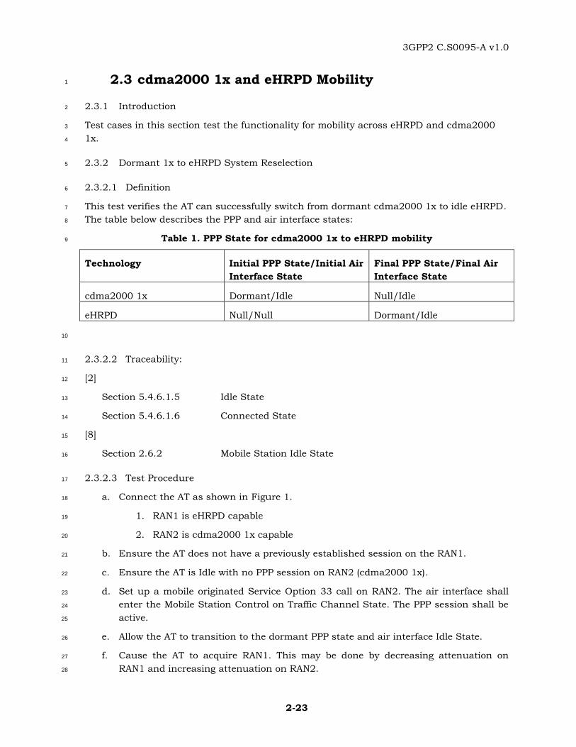
2.3 cdma2000 1x and eHRPD Mobility 1
2.3.1 Introduction 2
Test cases in this section test the functionality for mobility across eHRPD and cdma2000 3
1x. 4
2.3.2 Dormant 1x to eHRPD System Reselection 5
2.3.2.1 Definition 6
This test verifies the AT can successfully switch from dormant cdma2000 1x to idle eHRPD. 7
The table below describes the PPP and air interface states: 8
Table 1. PPP State for cdma2000 1x to eHRPD mobility 9
Technology Initial PPP State/Initial Air
Interface State
Final PPP State/Final Air
Interface State
cdma2000 1x Dormant/Idle Null/Idle
eHRPD Null/Null Dormant/Idle
10
2.3.2.2 Traceability: 11
[2] 12
Section 5.4.6.1.5 Idle State 13
Section 5.4.6.1.6 Connected State 14
[8] 15
Section 2.6.2 Mobile Station Idle State 16
2.3.2.3 Test Procedure 17
a. Connect the AT as shown in Figure 1. 18
1. RAN1 is eHRPD capable 19
2. RAN2 is cdma2000 1x capable 20
b. Ensure the AT does not have a previously established session on the RAN1. 21
c. Ensure the AT is Idle with no PPP session on RAN2 (cdma2000 1x). 22
d. Set up a mobile originated Service Option 33 call on RAN2. The air interface shall 23
enter the Mobile Station Control on Traffic Channel State. The PPP session shall be 24
active. 25
e. Allow the AT to transition to the dormant PPP state and air interface Idle State. 26
f. Cause the AT to acquire RAN1. This may be done by decreasing attenuation on 27
RAN1 and increasing attenuation on RAN2. 28
3GPP2 C.S0095-A v1.0
2-24
g. Verify the AT acquires RAN1. 1
h. Verify the AT negotiates the eHRPD session as specified in Section 2.1.2. 2
i. Initiate a data call on the eHRPD network (Note: The IP continuity will not be 3
maintained after switching from cdma2000 1x to eHRPD). See 2.9.2, 2.10.2, and 4
2.10.3 for PPP setup procedures. 5
j. Verify the call is successful and the AT can send/receive data using the eHRPD 6
network. 7
2.3.2.4 Minimum Standard 8
The AT shall comply with steps g, h, and j. 9
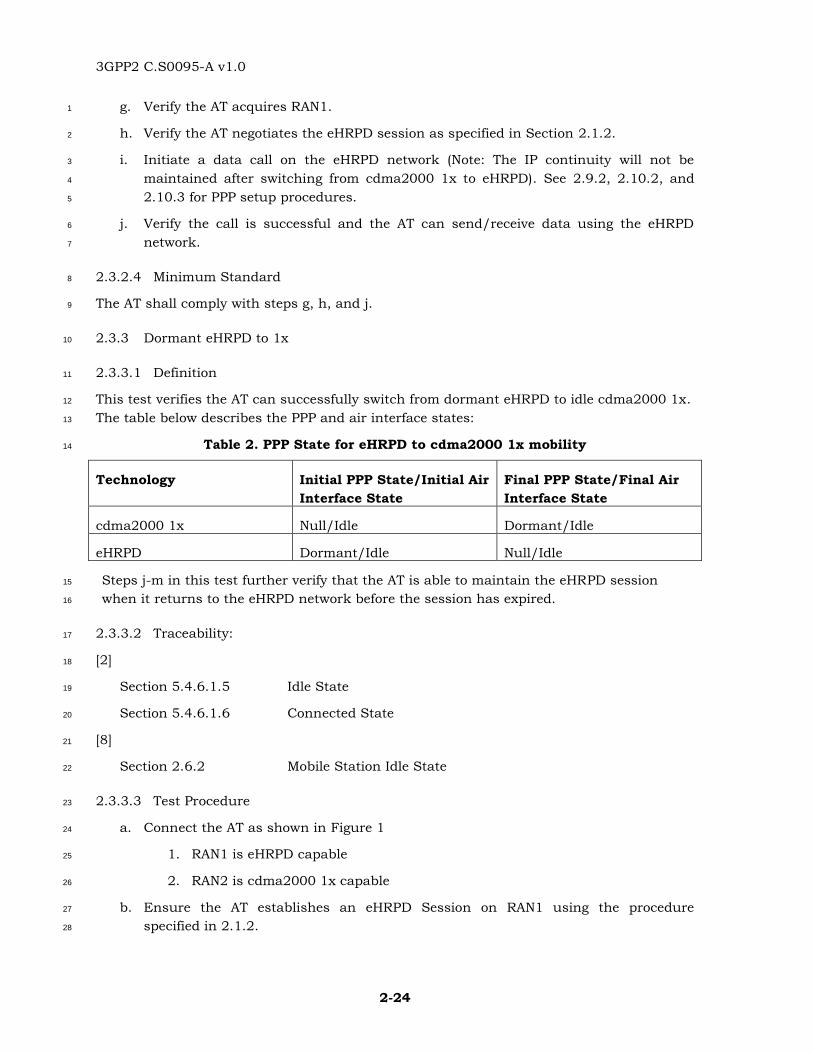
2.3.3 Dormant eHRPD to 1x 10
2.3.3.1 Definition 11
This test verifies the AT can successfully switch from dormant eHRPD to idle cdma2000 1x. 12
The table below describes the PPP and air interface states: 13
Table 2. PPP State for eHRPD to cdma2000 1x mobility 14
Technology Initial PPP State/Initial Air
Interface State
Final PPP State/Final Air
Interface State
cdma2000 1x Null/Idle Dormant/Idle
eHRPD Dormant/Idle Null/Idle
Steps j-m in this test further verify that the AT is able to maintain the eHRPD session 15
when it returns to the eHRPD network before the session has expired. 16
2.3.3.2 Traceability: 17
[2] 18
Section 5.4.6.1.5 Idle State 19
Section 5.4.6.1.6 Connected State 20
[8] 21
Section 2.6.2 Mobile Station Idle State 22
2.3.3.3 Test Procedure 23
a. Connect the AT as shown in Figure 1 24
1. RAN1 is eHRPD capable 25
2. RAN2 is cdma2000 1x capable 26
b. Ensure the AT establishes an eHRPD Session on RAN1 using the procedure 27
specified in 2.1.2. 28
3GPP2 C.S0095-A v1.0
2-25
c. Ensure the AT is Idle with no PPP session on RAN1. 1
d. Set up a mobile originated data call on RAN1. The air interface shall enter the 2
Connected State. The PPP state shall be active. 3
e. Allow the AT to transition to the dormant PPP state and air interface Idle State. 4
f. Cause the AT to acquire RAN2. This may be done by increasing attenuation on 5
RAN1 and decreasing attenuation on RAN2. 6
g. Verify the AT acquires RAN2. 7
h. Initiate a data call on the cdma2000 1x network (Note: The IP continuity will not be 8
maintained after switching from eHRPD to cdma2000 1x). 9
i. Verify the call is successful and the AT can send/receive data using the cdma2000 10
1x network. 11
j. Allow the AT to transition to the dormant PPP state and air interface Idle State. 12
k. Cause the AT to acquire RAN1. This may be done by decreasing attenuation on 13
RAN1 and increasing attenuation on RAN2. Note this step should occur before the 14
eHRPD session has expired. 15
l. Cause the AT to access the RAN1. 16
m. Verify the AT does not negotiate the eHRPD session, i.e. the AT sends a 17
ConnectionRequest message but does not send a UATIRequest message to the RAN. 18
2.3.3.4 Minimum Standard 19
The AT shall comply with steps g, i, and m. 20
2.3.4 Active eHRPD to Idle 1x 21
2.3.4.1 Definition 22
This test verifies the AT can successfully switch from active eHRPD to idle 1x. The table 23
below describes the PPP and air interface states: 24
Table 3. PPP State for Active eHRPD to cdma2000 1x mobility 25
Technology Initial PPP State/Initial Air
Interface State
Final PPP State/Final Air
Interface State
cdma2000 1x Null/Idle Dormant/Idle
eHRPD Active/Connected Null/Idle
26
2.3.4.2 Traceability: 27
[2] 28
Section 5.4.6.1.5 Idle State 29
3GPP2 C.S0095-A v1.0
2-26
Section 5.4.6.1.6 Connected State 1
[8] 2
Section 2.6.2 Mobile Station Idle State 3
2.3.4.3 Test Procedure 4
a. Connect the AT as shown in Figure 1 5
1. RAN1 is eHRPD capable 6
2. RAN2 is cdma2000 1x capable 7
b. Ensure there is no E-UTRAN available. 8
c. Ensure the AT establishes an eHRPD Session on RAN1 using the procedure 9
specified in 2.1.2. 10
d. Ensure the AT is Idle with no PPP session on RAN1. 11
e. Set up a mobile originated data call on RAN1. The air interface shall enter the 12
Connected State. The PPP state shall be active. 13
f. While the PPP state is still active, cause the AT to acquire RAN2. This may be done 14
by increasing attenuation on RAN1 and decreasing attenuation on RAN2. 15
g. Verify the AT and RAN1 terminate the active eHRPD call. 16
h. Verify the AT acquires RAN2. 17
i. Initiate a data call on the cdma2000 1x network (Note: The IP continuity will not be 18
maintained after switching from eHRPD to cdma2000 1x). The AT may initiate the 19
data call autonomously. 20
j. Verify the call is successful and the AT can send/receive data using the cdma2000 21
1x network 22
2.3.4.4 Minimum Standard 23
The AT shall comply with steps g, h, and j. 24
2.4 E-UTRA to eHRPD Handoff 25
2.4.1 Introduction 26
Test cases in this section test the functionality for E-UTRAN and eHRPD interworking 27
during system selection and handoffs. 28
2.4.2 E-UTRAN Idle to eHRPD Dormant Handoff – Previous eHRPD Session, No Pre-29
registration, A13-Session Information transfer available 30
2.4.2.1 Definition 31
This test verifies the AT can successfully perform an E-UTRAN Idle to eHRPD dormant 32
handoff. The network and device are not configured to support preregistration. The AT shall 33
3GPP2 C.S0095-A v1.0
2-27
have a previous eHRPD session on the source RAN. The source and target AN shall support 1
session transfer. The procedures for the AT to select the E-UTRAN network and for the E-2
UTRAN network and AT to handoff are outside the scope of this document. 3
2.4.2.2 Traceability: 4
[2] 5
Section 2.3 Packet Application Negotiation 6
Section 3.1 Additional Requirement to support eHRPD operation in 7
Enhanced Multi-Flow Packet Application or Multi-Link Multi-8
Flow Packet Application 9
Section 3.2 Additional Requirements to support eHRPD operation in 10
Multi-Flow Packet Application 11
[6] 12
Section 6.2.6.1.2 Processing the SessionClose Message 13
[3] 14
Section 12 Handoff from E-UTRAN to eHRPD 15
2.4.2.3 Test Procedure 16
a. Connect the device shown in Figure 2. RAN1 and RAN2 are eHRPD ANs on different 17
subnets. 18
b. Ensure the E-UTRAN network is configured to not allow preregistration. 19
c. Ensure the AT has a previously established session with the eHRPD RAN1 and is 20
currently dormant. See test case 2.1.2 for procedures regarding eHRPD session 21
negotiation. 22
d. Ensure that both the eHRPD and E-UTRAN systems are available to the AT. 23
e. Ensure the AT is currently idle on the E-UTRAN network. 24
f. Cause the AT to perform cell re-selection to the eHRPD RAN2. 25
g. Verify that once the AT acquires the eHRPD RAN2, the AT sends a UATIRequest 26
message. 27
h. Ensure that RAN2 sends an A13-Session Information Request to RAN1 to request 28
the session information 29
i. Ensure that RAN1 sends an A13-Session Information Response to RAN2. 30
j. Ensure that RAN2 sends a UATIAssignment message to the AT 31
k. Verify the AT sends a UATIComplete message. 32
l. Initiate a data call from the AT to RAN2. 33
m. Verify that the AT is able to send and receive data using ReservationLabel 0xFF. 34
3GPP2 C.S0095-A v1.0
2-28
2.4.2.4 Minimum Standard 1
The AT shall comply with steps g, k, and m. 2
2.4.3 E-UTRAN Idle to eHRPD Dormant Handoff – Previous eHRPD Session, No Pre-3
registration, A13- Session Information transfer not available 4
2.4.3.1 Definition 5
This test verifies the AT can successfully perform an E-UTRAN Idle to eHRPD dormant 6
handoff. The network and device are not configured to support preregistration. The AT 7
shall have a previous eHRPD session on the source RAN. The source and target RAN shall 8
not support session information transfer. The procedures for the AT to select the E-UTRAN 9
network and for the E-UTRAN network and AT to handoff are outside the scope of this 10
document. 11
2.4.3.2 Traceability: 12
[2] 13
Section 2.3 Packet Application Negotiation 14
Section 3.1 Additional Requirement to support eHRPD operation in 15
Enhanced Multi-Flow Packet Application or Multi-Link Multi-16
Flow Packet Application 17
Section 3.2 Additional Requirements to support eHRPD operation in 18
Multi-Flow Packet Application 19
[6] 20
Section 6.2.6.1.2 Processing the SessionClose Message 21
[3] 22
Section 12 Handoff from E-UTRAN to eHRPD 23
2.4.3.3 Test Procedure 24
a. Connect the device shown in Figure 2. RAN1 and RAN2 are eHRPD ANs on different 25
subnets. 26
b. Ensure the E-UTRAN network is configured to not allow preregistration. 27
c. Ensure the AT has a previously established session with the eHRPD RAN1 and is 28
currently dormant. See test case 2.1.2 for procedures regarding eHRPD session 29
negotiation. 30
d. Ensure that both the eHRPD and E-UTRAN systems are available to the AT. 31
e. Ensure the AT is currently idle on the E-UTRAN network. 32
f. Cause the AT to perform cell re-selection to the eHRPD RAN2. 33
g. Verify that once the AT acquires the eHRPD RAN2, the AT sends a UATIRequest 34
message. 35
3GPP2 C.S0095-A v1.0
2-29
h. Ensure RAN2 sends a SessionClose message to the AT. 1
i. Verify the AT sends a SessionClose message to RAN2. 2
j. Verify the AT sends a UATIRequest message to RAN2. 3
k. Ensure that RAN2 sends a UATIAssignment message to the AT. 4
l. Verify the AT sends a UATIComplete message. 5
m. Verify that the AT negotiates a new session with the RAN2. 6
n. Verify the AT completes session negotiation as specified in 2.1.2. 7
2.4.3.4 Minimum Standard 8
The AT shall comply with steps g, i, j, l, m and n. 9
2.4.4 E-UTRAN Idle to eHRPD Dormant Handoff – With Pre-registration, Without A13-10
Session Information transfer 11
2.4.4.1 Definition 12
This test verifies the AT can successfully perform an E-UTRAN Idle to eHRPD dormant 13
handoff when pre-registration has been completed. The network and device are configured 14
to support pre-registration. The AT shall perform pre-registration and maintain eHRPD 15
session with AN over S101 interface. It is assumed that the AT is about to idle handoff to 16
the same AN that the AT maintain pre-registered eHRPD session with. The procedures for 17
the AT to select the E-UTRAN network and for the E-UTRAN network and AT to handoff are 18
outside the scope of this document. 19
2.4.4.2 Traceability: 20
[2] 21
Section 2.3 Enhanced Multi-flow Packet Application Negotiation 22
Section 3.1 Additional Requirement to support eHRPD operation in 23
Enhanced Multi-Flow Packet Application or Multi-Link Multi-24
Flow Packet Application 25
Section 3.2 Additional Requirements to support eHRPD operation in 26
Multi-Flow Packet Application 27
Section 4.2 Default Address Management Protocol 28
Section 5.5 Inter-RAT Overhead Messages Protocol 29
[3] 30
Section 12 Handoff from E-UTRAN to eHRPD 31
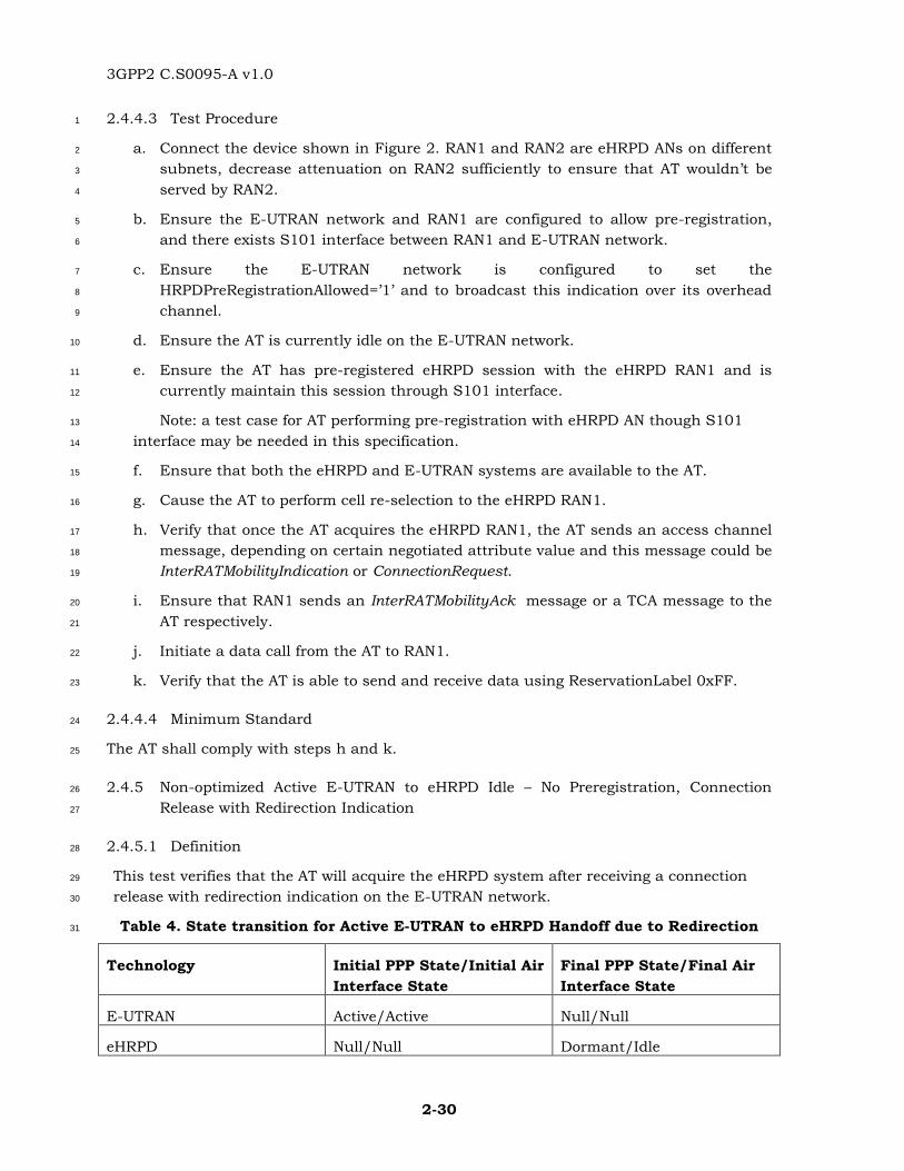
3GPP2 C.S0095-A v1.0
2-30
2.4.4.3 Test Procedure 1
a. Connect the device shown in Figure 2. RAN1 and RAN2 are eHRPD ANs on different 2
subnets, decrease attenuation on RAN2 sufficiently to ensure that AT wouldn’t be 3
served by RAN2. 4
b. Ensure the E-UTRAN network and RAN1 are configured to allow pre-registration, 5
and there exists S101 interface between RAN1 and E-UTRAN network. 6
c. Ensure the E-UTRAN network is configured to set the 7
HRPDPreRegistrationAllowed=’1’ and to broadcast this indication over its overhead 8
channel. 9
d. Ensure the AT is currently idle on the E-UTRAN network. 10
e. Ensure the AT has pre-registered eHRPD session with the eHRPD RAN1 and is 11
currently maintain this session through S101 interface. 12
Note: a test case for AT performing pre-registration with eHRPD AN though S101 13
interface may be needed in this specification. 14
f. Ensure that both the eHRPD and E-UTRAN systems are available to the AT. 15
g. Cause the AT to perform cell re-selection to the eHRPD RAN1. 16
h. Verify that once the AT acquires the eHRPD RAN1, the AT sends an access channel 17
message, depending on certain negotiated attribute value and this message could be 18
InterRATMobilityIndication or ConnectionRequest. 19
i. Ensure that RAN1 sends an InterRATMobilityAck message or a TCA message to the 20
AT respectively. 21
j. Initiate a data call from the AT to RAN1. 22
k. Verify that the AT is able to send and receive data using ReservationLabel 0xFF. 23
2.4.4.4 Minimum Standard 24
The AT shall comply with steps h and k. 25
2.4.5 Non-optimized Active E-UTRAN to eHRPD Idle – No Preregistration, Connection 26
Release with Redirection Indication 27
2.4.5.1 Definition 28
This test verifies that the AT will acquire the eHRPD system after receiving a connection 29
release with redirection indication on the E-UTRAN network. 30
Table 4. State transition for Active E-UTRAN to eHRPD Handoff due to Redirection 31
Technology Initial PPP State/Initial Air
Interface State
Final PPP State/Final Air
Interface State
E-UTRAN Active/Active Null/Null
eHRPD Null/Null Dormant/Idle

3GPP2 C.S0095-A v1.0
2-31
2.4.5.2 Traceability: 1
[2] 2
Section 3.1 Additional Requirement to support eHRPD operation in 3
Enhanced Multi-Flow Packet Application or Multi-Link Multi-4
Flow Packet Application 5
Section 3.2 Additional Requirements to support eHRPD operation in 6
Multi-Flow Packet Application 7
[3] 8
Section 4.4.1.1.1 IP Address Allocation: VSNCP Configure-Request 9
Section 9.1.4.1 3GPP2 VSNCP Configuration Options 10
Section 9.1.4.2 3GPP2 VSNCP Configure-Request 11
[9] 12
Section 8.1.4 RRC Connection Release 13
2.4.5.3 Test Procedure 14
a. Connect the AT as shown in Figure 2. Note that only one eHRPD RAN and one E-15
UTRAN RAN are needed. 16
1) RAN1 is eHRPD capable 17
2) RAN3 is E-UTRAN capable 18
b. The AT may or may not have a previously established session on RAN1. See 2.1.2 19
for procedures on establishing a new eHRPD session. 20
c. Ensure the AT is in the ECM_Idle state on RAN3. 21
d. Set up a mobile originated data call on RAN3. The air interface shall enter the active 22
state. The PPP session shall be active. 23
e. Cause the AN to send a RRCConnectionRelease message directing the AT to RAN1. 24
f. Verify the AT acquires RAN1. 25
g. Verify the AT attaches to the eHRPD network. If the AT did not have a previous 26
eHRPD session or the existing session has expired, see 2.1.2 for eHRPD session 27
negotiation. 28
h. Ensure that the application requesting data connection remains active. 29
i. Verify that the AT sends PPP: VSNCP-Configure-Request message containing the 30
following fields: 31
1) PDN Type = IPv4, IPv6, IPv4v6 32
2) PDN Address = [Valid IP address of AT for APN] 33
3) Attach Type = 3 (Handover) 34
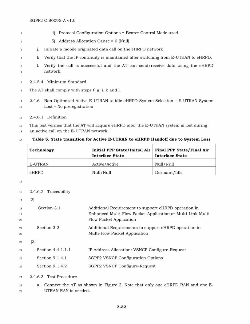
3GPP2 C.S0095-A v1.0
2-32
4) Protocol Configuration Options = Bearer Control Mode used 1
5) Address Allocation Cause = 0 (Null) 2
j. Initiate a mobile originated data call on the eHRPD network 3
k. Verify that the IP continuity is maintained after switching from E-UTRAN to eHRPD. 4
l. Verify the call is successful and the AT can send/receive data using the eHRPD 5
network. 6
2.4.5.4 Minimum Standard 7
The AT shall comply with steps f, g, i, k and l. 8
2.4.6 Non-Optimized Active E-UTRAN to idle eHRPD System Selection – E-UTRAN System 9
Lost – No preregistration 10
2.4.6.1 Definition 11
This test verifies that the AT will acquire eHRPD after the E-UTRAN system is lost during 12
an active call on the E-UTRAN network. 13
Table 5. State transition for Active E-UTRAN to eHRPD Handoff due to System Loss 14
Technology Initial PPP State/Initial Air
Interface State
Final PPP State/Final Air
Interface State
E-UTRAN Active/Active Null/Null
eHRPD Null/Null Dormant/Idle
15
2.4.6.2 Traceability: 16
[2] 17
Section 3.1 Additional Requirement to support eHRPD operation in 18
Enhanced Multi-Flow Packet Application or Multi-Link Multi-19
Flow Packet Application 20
Section 3.2 Additional Requirements to support eHRPD operation in 21
Multi-Flow Packet Application 22
[3] 23
Section 4.4.1.1.1 IP Address Allocation: VSNCP Configure-Request 24
Section 9.1.4.1 3GPP2 VSNCP Configuration Options 25
Section 9.1.4.2 3GPP2 VSNCP Configure-Request 26
2.4.6.3 Test Procedure 27
a. Connect the AT as shown in Figure 2. Note that only one eHRPD RAN and one E-28
UTRAN RAN is needed. 29
3GPP2 C.S0095-A v1.0
2-33
1. RAN1 is eHRPD capable 1
2. RAN3 is E-UTRAN capable 2
b. The AT may or may not have a previously established session on the RAN1. See 3
2.1.2 for procedures on establishing a new eHRPD session. 4
c. Ensure the AT is in the ECM_Idle state on RAN3. 5
d. Set up a mobile originated data call on RAN3. The air interface shall enter the active 6
state. 7
e. Attenuate the RF on RAN3 sufficiently so that the call is dropped and the device 8
enters the system determination. Ensure the RF impairments on RAN3 will prevent 9
the device from acquiring it. 10
f. Verify the AT acquires RAN1. 11
g. Verify the AT attaches to the eHRPD network. If the AT did not have a previous 12
eHRPD session or the existing session has expired, see 2.1.2 for eHRPD session 13
negotiation. 14
h. Initiate a mobile originated data call on the eHRPD network. 15
i. Verify that the AT sends PPP: VSNCP-Configure-Request message containing the 16
following fields: 17
1) PDN Type = IPv4, IPv6, IPv4v6 18
2) PDN Address = [Valid IP address of AT for APN] 19
3) Attach Type = 3 (Handover) 20
4) Protocol Configuration Options = Bearer Control Mode used 21
5) Address Allocation Cause = 0 (Null) 22
j. Verify that the IP continuity is maintained after switching from E-UTRAN to eHRPD. 23
k. Verify the call is successful and the AT can send/receive data using the eHRPD 24
network. 25
2.4.6.4 Minimum Standard 26
The AT shall comply with steps f, g, i, j and k. 27
28
29
2.5 eHRPD to Idle E-UTRAN Handoff 30
2.5.1 Introduction 31
Test cases in this section test the functionality for eHRPD to E-UTRAN interworking during 32
system selection and handoffs. 33
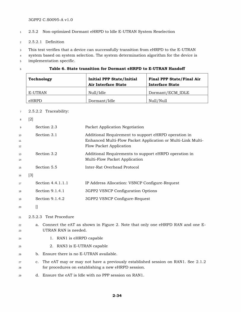
3GPP2 C.S0095-A v1.0
2-34
2.5.2 Non-optimized Dormant eHRPD to Idle E-UTRAN System Reselection 1
2.5.2.1 Definition 2
This test verifies that a device can successfully transition from eHRPD to the E-UTRAN 3
system based on system selection. The system determination algorithm for the device is 4
implementation specific. 5
Table 6. State transition for Dormant eHRPD to E-UTRAN Handoff 6
Technology Initial PPP State/Initial
Air Interface State
Final PPP State/Final Air
Interface State
E-UTRAN Null/Idle Dormant/ECM_IDLE
eHRPD Dormant/Idle Null/Null
2.5.2.2 Traceability: 7
[2] 8
Section 2.3 Packet Application Negotiation 9
Section 3.1 Additional Requirement to support eHRPD operation in 10
Enhanced Multi-Flow Packet Application or Multi-Link Multi-11
Flow Packet Application 12
Section 3.2 Additional Requirements to support eHRPD operation in 13
Multi-Flow Packet Application 14
Section 5.5 Inter-Rat Overhead Protocol 15
[3] 16
Section 4.4.1.1.1 IP Address Allocation: VSNCP Configure-Request 17
Section 9.1.4.1 3GPP2 VSNCP Configuration Options 18
Section 9.1.4.2 3GPP2 VSNCP Configure-Request 19
[] 20
2.5.2.3 Test Procedure 21
a. Connect the eAT as shown in Figure 2. Note that only one eHRPD RAN and one E-22
UTRAN RAN is needed. 23
1. RAN1 is eHRPD capable 24
2. RAN3 is E-UTRAN capable 25
b. Ensure there is no E-UTRAN available. 26
c. The eAT may or may not have a previously established session on RAN1. See 2.1.2 27
for procedures on establishing a new eHRPD session. 28
d. Ensure the eAT is Idle with no PPP session on RAN1. 29
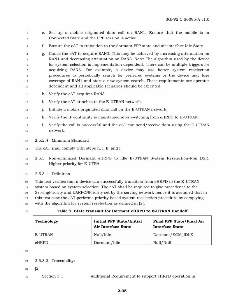
3GPP2 C.S0095-A v1.0
2-35
e. Set up a mobile originated data call on RAN1. Ensure that the mobile is in 1
Connected State and the PPP session is active. 2
f. Ensure the eAT to transition to the dormant PPP state and air interface Idle State. 3
g. Cause the eAT to acquire RAN3. This may be achieved by increasing attenuation on 4
RAN1 and decreasing attenuation on RAN3. Note: The algorithm used by the device 5
for system selection is implementation dependent. There can be multiple triggers for 6
acquiring RAN3. For example, a device may use better system reselection 7
procedures to periodically search for preferred systems or the device may lose 8
coverage of RAN1 and start a new system search. These requirements are operator 9
dependent and all applicable scenarios should be executed. 10
h. Verify the eAT acquires RAN3. 11
i. Verify the eAT attaches to the E-UTRAN network. 12
j. Initiate a mobile originated data call on the E-UTRAN network. 13
k. Verify the IP continuity is maintained after switching from eHRPD to E-UTRAN. 14
l. Verify the call is successful and the eAT can send/receive data using the E-UTRAN 15
network. 16
2.5.2.4 Minimum Standard 17
The eAT shall comply with steps h, i, k, and l. 18
2.5.3 Non-optimized Dormant eHRPD to Idle E-UTRAN System Reselection-Non BSR, 19
Higher priority for E-UTRA 20
2.5.3.1 Definition 21
This test verifies that a device can successfully transition from eHRPD to the E-UTRAN 22
system based on system selection. The eAT shall be required to give precedence to the 23
ServingPriority and EARFCNPriority set by the serving network hence it is assumed that in 24
this test case the eAT performs priority based system reselection procedure by complying 25
with the algorithm for system reselection as defined in [2]. 26
Table 7. State transmit for Dormant eHRPD to E-UTRAN Handoff 27
Technology Initial PPP State/Initial
Air Interface State
Final PPP State/Final Air
Interface State
E-UTRAN Null/Idle Dormant/ECM_IDLE
eHRPD Dormant/Idle Null/Null
28
2.5.3.2 Traceability: 29
[2] 30
Section 3.1 Additional Requirement to support eHRPD operation in 31
3GPP2 C.S0095-A v1.0
2-36
Enhanced Multi-Flow Packet Application or Multi-Link Multi-1
Flow Packet Application 2
Section 3.2 Additional Requirements to support eHRPD operation in 3
Multi-Flow Packet Application 4
Section 5.5 Inter-Rat Overhead Message Protocol 5
Section 7.1 E-UTRAN Neighbor List Record 6
Section 8.1 EUTRA Neighbor Channels Management and EUTRA Idle 7
Channel Reselection Procedures 8
2.5.3.3 Test Procedure 9
a. Connect the eAT as shown in Figure 2 10
3. RAN1 is eHRPD capable 11
4. RAN3 is E-UTRAN capable 12
b. Ensure there is no E-UTRAN available. 13
c. The eAT may or may not have a previously established session on RAN1. See 2.1.2 14
for procedures on establishing a new eHRPD session. 15
d. Ensure the eAT is Idle with no PPP session on RAN1. 16
e. Set up a mobile originated data call on RAN1. Ensure that the mobile is in 17
Connected State and the PPP session is active. 18
f. Ensure the eAT to transition to the dormant PPP state and air interface Idle State. 19
g. Set the ServingPriority field in eHRPD's OtherRATNeighborList messag to ensure the 20
E-UTRA frequency channel on RAN3 has higher priority than eHRPD channel on 21
RAN1 and the eAT can acquire the priority information (in ServingPriority field) from 22
eHRPD OtherRATNeighborList message. 23
h. Decrease attenuation on RAN3 sufficiently to make sure that the Srxlev-value of the 24
E-UTRA frequency channel is equal to or greater than its corresponding ThreshX.25
26
Note: RSRQ criterion is introduced in C.S0087-A v1.0. 27
i. Verify the eAT acquires RAN3. 28
j. Verify the eAT attaches to the E-UTRAN network. 29
k. Initiate a mobile originated data call on the E-UTRAN network. 30
l. Verify the IP continuity is maintained after switching from eHRPD to E-UTRAN. 31
m. Verify the call is successful and the eAT can send/receive data using the E-UTRAN 32
network. 33
2.5.3.4 Minimum Standard 34
The eAT shall comply with steps i, j, l, and m. 35
3GPP2 C.S0095-A v1.0
2-37
2.5.4 Non-optimized Dormant eHRPD to Idle E-UTRAN System Reselection-Non BSR, 1
Higher priority for eHRPD 2
2.5.4.1 Definition 3
This test verifies that a device can successfully transition from eHRPD to the E-UTRAN 4
system based on system selection. The eAT shall be required to give precedence to the 5
ServingPriority and EARFCNPriority set by the serving network hence it is assumed that in 6
this test case the eAT performs priority based system reselection procedure by complying 7
with the algorithm for system reselection as defined in [2]. 8
Table 8. PPP State for Dormant eHRPD to E-UTRAN Handoff 9
Technology Initial PPP State/Initial
Air Interface State
Final PPP State/Final Air
Interface State
E-UTRAN Null/Idle Dormant/ECM_IDLE
eHRPD Dormant/Idle Null/Null
10
2.5.4.2 Traceability: 11
[2] 12
Section 3.1 Additional Requirement to support eHRPD operation in 13
Enhanced Multi-Flow Packet Application or Multi-Link Multi-14
Flow Packet Application 15
Section 3.2 Additional Requirements to support eHRPD operation in 16
Multi-Flow Packet Application 17
Section 5.5 Inter-Rat Overhead Message Protocol 18
Section 7.1 E-UTRAN Neighbor List Record 19
Section 8.1 EUTRA Neighbor Channels Management and EUTRA Idle 20
Channel Reselection Procedures 21
2.5.4.3 Test Procedure 22
a. Connect the eAT as shown in Figure 2. 23
1. RAN1 is eHRPD capable 24
2. RAN2 is E-UTRAN capable 25
b. Ensure there is no E-UTRAN available. 26
c. The eAT may or may not have a previously established session on RAN1. See 2.1.2 27
for procedures on establishing a new eHRPD session. 28
d. Ensure the eAT is Idle with no PPP session on RAN1. 29

3GPP2 C.S0095-A v1.0
2-38
e. Set up a mobile originated data call on RAN1. Ensure that the mobile is in 1
Connected State and the PPP session is active. 2
f. Ensure the eAT to transition to the dormant PPP state and air interface Idle State. 3
g. Ensure the eHRPD channel on RAN1 has higher priority than the E-UTRA frequency 4
channel on RAN2 and the eAT can acquire the priority information (in 5
ServingPriority field) from eHRPD OtherRATNeighborList message. 6
h. Decrease attenuation on RAN2 sufficiently to make sure that the Srxlev-value of the 7
E-UTRA frequency channel is equal to or greater than its corresponding ThreshX 8
while increasing attenuation on RAN1 such that the strength of the reference pilot of 9
the serving eHRPD network is less than the ThreshServing. 10
Note: RSRQ criterion is introduced in C.S0087-A v1.0. 11
i. Verify the eAT acquires RAN2. 12
j. Verify the eAT attaches to the E-UTRAN network. 13
k. Initiate a mobile originated data call on the E-UTRAN network. 14
l. Verify the IP continuity is maintained after switching from eHRPD to E-UTRAN. 15
m. Verify the call is successful and the eAT can send/receive data using the E-UTRAN 16
network. 17
2.5.4.4 Minimum Standard 18
The eAT shall comply with steps i, j, l, and m. 19
2.5.5 Active eHRPD to E-UTRAN Handoff 20
2.5.5.1 Definition 21
This test verifies that the access terminal can successfully handoff from active eHRPD to E-22
UTRAN based on Inter-RAT Redirection procedure defined in [2]. 23
Table 9. State transition for active eHRPD to E-UTRAN handoff due to redirection 24
Technology Initial PPP State/Initial
Air Interface State
Final PPP State/Final Air
Interface State
eHRPD Active/Active Null/Null
E-UTRAN Null/ECM_IDLE Active/ECM_CONNECTED
25
2.5.5.2 Traceability: 26
[2] 27
Section 3.1 Additional Requirement to support eHRPD operation in 28
Enhanced Multi-Flow Packet Application or Multi-Link Multi-29
Flow Packet Application 30
3GPP2 C.S0095-A v1.0
2-39
Section 3.2 Additional Requirements to support eHRPD operation in 1
Multi-Flow Packet Application 2
Section 5.7 Default Air-Link Management Protocol 3
2.5.5.3 Test Procedure 4
a. Connect the eAT as shown in Figure 2. Note that only one eHRPD RAN and one E-5
UTRAN RAN are needed. 6
1. RAN1 is eHRPD capable. 7
2. RAN3 is E-UTRAN capable. 8
b. Ensure there is no E-UTRAN available. 9
c. Ensure the eAT is in the Idle state with no PPP session on RAN1. 10
d. Set up a mobile originated data call on RAN1. Ensure that the mobile is in 11
Connected State and the PPP session is active. 12
e. Adjust the RF on RAN3 so that its signal strength is good enough to be acquired by 13
the eAT. 14
f. Ensure the RAN1 to send an OtherRATMeasurementRequest message to the eAT. 15
g. Verify that the eAT sends an OtherRATMeasurementReport message to RAN1. 16
h. Ensure the RAN1 to send an InterRATRedirect message to the eAT. 17
i. Verify that the eAT attaches and connects to the E-UTRAN network. 18
j. Ensure that the application requesting data connection remains active. 19
k. Verify that the IP continuity is maintained after switching from eHRPD to E-UTRAN. 20
l. Verify that the call is successful and the eAT can send/receive data over the E-21
UTRAN network. 22
2.5.5.4 Minimum Standard 23
The eAT shall comply with steps g, i, k, l. 24
2.5.6 Ping-ponging: Lost eHRPD and LTE, Partial HSGW context available, A13 available 25
2.5.6.1 Definition 26
This test verifies the eAT can successfully maintain IP contexts while performing transitions 27
from a dormant eHRPD RAN to an idle E-UTRAN RAN to a different eHRPD RAN and back 28
to the idle E-UTRAN. The networks and device are not configured to support 29
preregistration. The eAT shall have a previous eHRPD session on the source RAN. The 30
source and target AN shall support session transfer. The procedures for the eAT to select 31
the E-UTRAN network and for the E-UTRAN network and eAT to handoff are outside the 32
scope of this document. 33
3GPP2 C.S0095-A v1.0
2-40
2.5.6.2 Traceability 1
[2] 2
Section 2.3 Packet Application Negotiation 3
Section 3.1 Additional Requirement to support eHRPD operation in 4
Enhanced Multi-Flow Packet Application or Multi-Link Multi-5
Flow Packet Application 6
Section 3.2 Additional Requirements to support eHRPD operation in 7
Multi-Flow Packet Application 8
[6] 9
Section 6.2.6.1.2 Processing the SessionClose Message 10
[3] 11
Section 13.2.2 Idle Mode Mobility from E-UTRAN to eHRPD (Different 12
eAN/ePCF) 13
2.5.6.3 Test Procedure 14
a. Connect the device shown in Figure 2. RAN1 and RAN2 are eHRPD ANs on different 15
subnets. 16
b. Ensure the E-UTRAN network is configured to not allow preregistration. 17
c. Ensure the eAT has a previously established session with the eHRPD RAN1 and is 18
currently dormant. See test case 2.1.2 for procedures regarding eHRPD session 19
negotiation. 20
d. Turn off the power to (eHRPD) RAN1 and wait 10 seconds. 21
e. Turn on the power to (E-UTRAN) RAN3. 22
f. Verify that the eAT attaches to RAN3 and maintains IP contexts. 23
g. Wait for the eAT to enter RRC_IDLE state on RAN3. Then turn off the power to RAN3 24
and wait 10 seconds. 25
h. Turn on the power to (eHRPD) RAN2. 26
i. Verify that the eAT attaches to RAN2 and sends a UATIRequest message. 27
j. Ensure that RAN2 sends an A13-Session Information Request to RAN1 to request 28
the session information. 29
k. Ensure that RAN2 sends a UATIAssignment message to the eAT. 30
l. Verify the eAT sends a UATIComplete message. 31
m. Wait for the eAT to enter dormant state on RAN2. Then turn off the power to RAN2 32
and wait 10 seconds. 33
n. Turn on the power to (E-UTRAN) RAN3. 34
o. Verify that the eAT attaches to RAN3 and maintains IP contexts. 35
3GPP2 C.S0095-A v1.0
2-41
2.5.6.4 Minimum Standard 1
The eAT shall comply with steps f, i, l and o. 2
2.5.7 Ping-ponging: Lost eHRPD and LTE, Partial HSGW context available, A13 not 3
available 4
2.5.7.1 Definition 5
This test verifies the eAT can successfully maintain IP contexts while performing transitions 6
from a dormant eHRPD RAN to an idle E-UTRAN RAN to a different eHRPD RAN and back 7
to the idle E-UTRAN. The networks and device are not configured to support 8
preregistration. The eAT shall have a previous eHRPD session on the source RAN. The 9
source and target AN shall not support session transfer. The procedures for the eAT to 10
select the E-UTRAN network and for the E-UTRAN network and eAT to handoff are outside 11
the scope of this document. 12
2.5.7.2 Traceability 13
[2] 14
Section 2.3 Packet Application Negotiation 15
Section 3.1 Additional Requirement to support eHRPD operation in 16
Enhanced Multi-Flow Packet Application or Multi-Link Multi-17
Flow Packet Application 18
Section 3.2 Additional Requirements to support eHRPD operation in 19
Multi-Flow Packet Application 20
[6] 21
Section 6.2.6.1.2 Processing the SessionClose Message 22
[3] 23
Section 12 Handoff from E-UTRAN to eHRPD 24
2.5.7.3 Test Procedure 25
a. Connect the device shown in Figure 2. RAN1 and RAN2 are eHRPD ANs on different 26
subnets. 27
b. Ensure the E-UTRAN network is configured to not allow preregistration. 28
c. Ensure the eAT has a previously established session with the eHRPD RAN1 and is 29
currently dormant. See test case 2.1.2 for procedures regarding eHRPD session 30
negotiation. 31
d. Turn off the power to (eHRPD) RAN1 and wait 10 seconds. 32
e. Turn on the power to (E-UTRAN) RAN3. 33
f. Verify that the eAT attaches to RAN3 and maintains IP contexts. 34
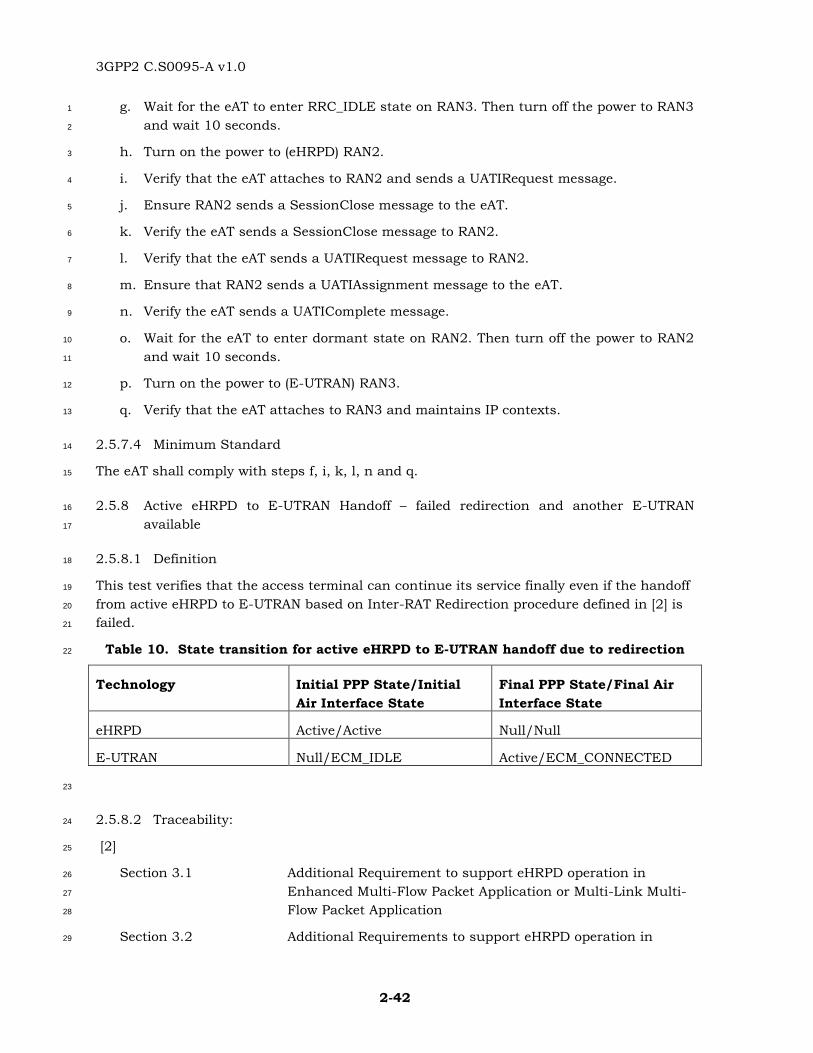
3GPP2 C.S0095-A v1.0
2-42
g. Wait for the eAT to enter RRC_IDLE state on RAN3. Then turn off the power to RAN3 1
and wait 10 seconds. 2
h. Turn on the power to (eHRPD) RAN2. 3
i. Verify that the eAT attaches to RAN2 and sends a UATIRequest message. 4
j. Ensure RAN2 sends a SessionClose message to the eAT. 5
k. Verify the eAT sends a SessionClose message to RAN2. 6
l. Verify that the eAT sends a UATIRequest message to RAN2. 7
m. Ensure that RAN2 sends a UATIAssignment message to the eAT. 8
n. Verify the eAT sends a UATIComplete message. 9
o. Wait for the eAT to enter dormant state on RAN2. Then turn off the power to RAN2 10
and wait 10 seconds. 11
p. Turn on the power to (E-UTRAN) RAN3. 12
q. Verify that the eAT attaches to RAN3 and maintains IP contexts. 13
2.5.7.4 Minimum Standard 14
The eAT shall comply with steps f, i, k, l, n and q. 15
2.5.8 Active eHRPD to E-UTRAN Handoff – failed redirection and another E-UTRAN 16
available 17
2.5.8.1 Definition 18
This test verifies that the access terminal can continue its service finally even if the handoff 19
from active eHRPD to E-UTRAN based on Inter-RAT Redirection procedure defined in [2] is 20
failed. 21
Table 10. State transition for active eHRPD to E-UTRAN handoff due to redirection 22
Technology Initial PPP State/Initial
Air Interface State
Final PPP State/Final Air
Interface State
eHRPD Active/Active Null/Null
E-UTRAN Null/ECM_IDLE Active/ECM_CONNECTED
23
2.5.8.2 Traceability: 24
[2] 25
Section 3.1 Additional Requirement to support eHRPD operation in 26
Enhanced Multi-Flow Packet Application or Multi-Link Multi-27
Flow Packet Application 28
Section 3.2 Additional Requirements to support eHRPD operation in 29
3GPP2 C.S0095-A v1.0
2-43
Multi-Flow Packet Application 1
Section 5.7 Default Air-Link Management Protocol 2
2.5.8.3 Test Procedure 3
a. Connect the eAT as shown in Figure 3. Note that one eHRPD RAN and two E-UTRAN 4
RANs are needed. 5
1. RAN1 is eHRPD. 6
2. RAN2 is E-UTRAN. 7
3. RAN3 is E-UTRAN . 8
b. Ensure there is no E-UTRAN available. 9
c. Ensure the eAT is in the Idle state with no PPP session on RAN1. 10
d. Setup a mobile originated data call on RAN1. The air interface shall enter the active 11
state. The PPP session shall be active. 12
e. Adjust the RF on RAN2 so that its signal strength is good enough to be acquired by 13
the eAT and ensure RAN3 is not available by the eAT. 14
f. Ensure the RAN1 to send an OtherRATMeasurementRequest message to the eAT.. 15
g. Verify that the eAT sends an OtherRATMeasurementReport message to RAN1. 16
h. Adjust the RF on RAN3 so that it signal strength is good enough to be acquired by 17
the eAT and ensure RAN2 is not available by the eAT. 18
i. Ensure the RAN1 to send an InterRATRedirect message to the eAT. 19
j. Verify that the eAT attaches and connects to RAN3. 20
k. Ensure that the application requesting data connection remains active. 21
l. Verify that the IP continuity is maintained after switching from eHRPD to E-UTRAN. 22
m. Verify that the call is successful and the eAT can send/receive data over RAN3. 23
2.5.8.4 Minimum Standard 24
The eAT shall comply with steps g,j, l, m. 25
2.5.9 Active eHRPD to E-UTRAN Handoff – failed redirection and no other E-UTRAN 26
available 27
2.5.9.1 Definition 28
This test verifies that the access terminal can continue its service finally even if the handoff 29
from active eHRPD to E-UTRAN based on Inter-RAT Redirection procedure defined in [2] is 30
failed. 31
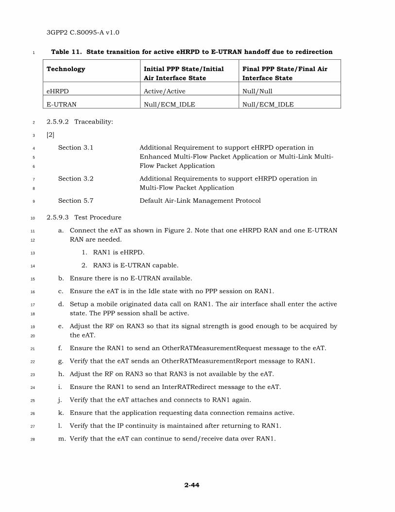
3GPP2 C.S0095-A v1.0
2-44
Table 11. State transition for active eHRPD to E-UTRAN handoff due to redirection 1
Technology Initial PPP State/Initial
Air Interface State
Final PPP State/Final Air
Interface State
eHRPD Active/Active Null/Null
E-UTRAN Null/ECM_IDLE Null/ECM_IDLE
2.5.9.2 Traceability: 2
[2] 3
Section 3.1 Additional Requirement to support eHRPD operation in 4
Enhanced Multi-Flow Packet Application or Multi-Link Multi-5
Flow Packet Application 6
Section 3.2 Additional Requirements to support eHRPD operation in 7
Multi-Flow Packet Application 8
Section 5.7 Default Air-Link Management Protocol 9
2.5.9.3 Test Procedure 10
a. Connect the eAT as shown in Figure 2. Note that one eHRPD RAN and one E-UTRAN 11
RAN are needed. 12
1. RAN1 is eHRPD. 13
2. RAN3 is E-UTRAN capable. 14
b. Ensure there is no E-UTRAN available. 15
c. Ensure the eAT is in the Idle state with no PPP session on RAN1. 16
d. Setup a mobile originated data call on RAN1. The air interface shall enter the active 17
state. The PPP session shall be active. 18
e. Adjust the RF on RAN3 so that its signal strength is good enough to be acquired by 19
the eAT. 20
f. Ensure the RAN1 to send an OtherRATMeasurementRequest message to the eAT. 21
g. Verify that the eAT sends an OtherRATMeasurementReport message to RAN1. 22
h. Adjust the RF on RAN3 so that RAN3 is not available by the eAT. 23
i. Ensure the RAN1 to send an InterRATRedirect message to the eAT. 24
j. Verify that the eAT attaches and connects to RAN1 again. 25
k. Ensure that the application requesting data connection remains active. 26
l. Verify that the IP continuity is maintained after returning to RAN1. 27
m. Verify that the eAT can continue to send/receive data over RAN1. 28
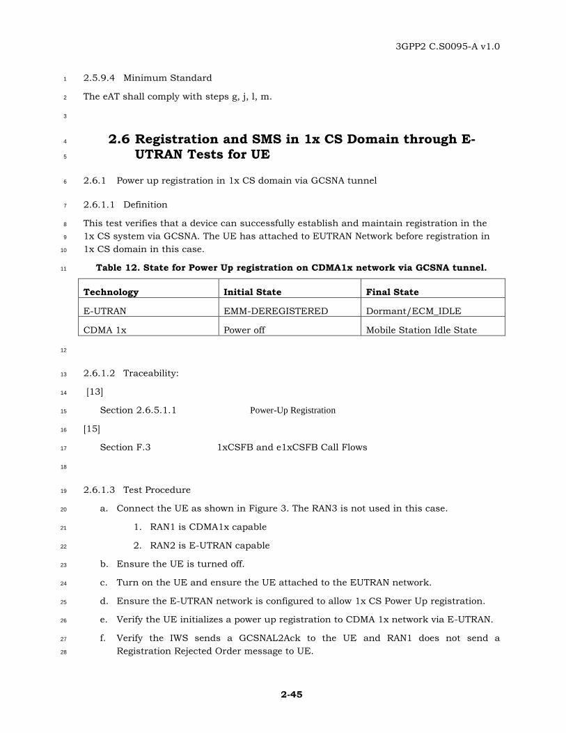
3GPP2 C.S0095-A v1.0
2-45
2.5.9.4 Minimum Standard 1
The eAT shall comply with steps g, j, l, m. 2
3
2.6 Registration and SMS in 1x CS Domain through E-4
UTRAN Tests for UE 5
2.6.1 Power up registration in 1x CS domain via GCSNA tunnel 6
2.6.1.1 Definition 7
This test verifies that a device can successfully establish and maintain registration in the 8
1x CS system via GCSNA. The UE has attached to EUTRAN Network before registration in 9
1x CS domain in this case. 10
Table 12. State for Power Up registration on CDMA1x network via GCSNA tunnel. 11
Technology Initial State Final State
E-UTRAN EMM-DEREGISTERED Dormant/ECM_IDLE
CDMA 1x Power off Mobile Station Idle State
12
2.6.1.2 Traceability: 13
[13] 14
Section 2.6.5.1.1 Power-Up Registration 15
[15] 16
Section F.3 1xCSFB and e1xCSFB Call Flows 17
18
2.6.1.3 Test Procedure 19
a. Connect the UE as shown in Figure 3. The RAN3 is not used in this case. 20
1. RAN1 is CDMA1x capable 21
2. RAN2 is E-UTRAN capable 22
b. Ensure the UE is turned off. 23
c. Turn on the UE and ensure the UE attached to the EUTRAN network. 24
d. Ensure the E-UTRAN network is configured to allow 1x CS Power Up registration. 25
e. Verify the UE initializes a power up registration to CDMA 1x network via E-UTRAN. 26
f. Verify the IWS sends a GCSNAL2Ack to the UE and RAN1 does not send a 27
Registration Rejected Order message to UE. 28

3GPP2 C.S0095-A v1.0
2-46
1
2.6.1.4 Minimum Standard 2
The UE shall comply with steps e and f. 3
4
2.6.2 Power Down registration in 1x CS domain via GCSNA tunnel 5
2.6.2.1 Definition 6
This test verifies that a device can successfully establish and maintain registration in the 7
1x CS system via GCSNA when user power off the mobile. The UE has attached to EUTRAN 8
Network before registration in 1x CS domain in this case. 9
Table 13. State for Power Down registration on CDMA1x network via GCSNA tunnel. 10
Technology Initial Air Interface State Final Air Interface State
E-UTRAN Dormant/ECM_IDLE EMM-DEREGISTERED
CDMA 1x Mobile Station Idle State Power off
11
2.6.2.2 Traceability: 12
[13] 13
Section 2.6.5.1.2 Power-Down Registration 14
[15] 15
Section F.3 1xCSFB and e1xCSFB Call Flows 16
17
2.6.2.3 Test Procedure 18
a. Connect the UE as shown in Figure 3 19
1. RAN1 is CDMA1x. 20
2. RAN2 is E-UTRAN. 21
b. Ensure the UE is turned on and attached to the EUTRAN network. 22
c. Ensure the E-UTRAN network is configured to allow 1x CS Power Down registration. 23
d. Ensure tester direct the UE to power off. 24
e. Ensure the E-UTRAN network is configured to allow 1x CS registration. 25
f. Verify the UE initializes a power down registration to CDMA 1x network via E-26
UTRAN. The UE does not perform power down registration if it has not previously 27
registered in the system that corresponds to the current SIDs and NIDs. 28
g. Verify IWS sends GCSNAL2Ack. 29

3GPP2 C.S0095-A v1.0
2-47
h. Verify the UE does not power off until it receives GCSNAL2Ack. 1
2
2.6.2.4 Minimum Standard 3
The UE shall comply with steps f, g and h. 4
5
2.6.3 Timer Based Registration in 1x CS Domain via GCSNA Tunnel 6
2.6.3.1 Definition 7
This test verifies that a device can successfully establish and maintain timer base 8
registration in the 1x CS system via GCSNA. The UE has already attached to EUTRAN 9
Network and registered in 1x CS domain. The UE camps in E-UTRAN and triggers periodic 10
LAU per the periodic timer received from power up 1x CS registration. 11
Table 14. State for Power Up registration on CDMA1x network via GCSNA tunnel. 12
Technology Initial Air Interface State Final Air Interface State
E-UTRAN Dormant/ECM_IDLE Dormant/ECM_IDLE
CDMA 1x Mobile Station Idle State Mobile Station Idle State
13
2.6.3.2 Traceability: 14
[5] 15
Section 2.6.5.1.3 Timer-Based Registration 16
[15] 17
Section F.3 1xCSFB and e1xCSFB Call Flows 18
19
2.6.3.3 Test Procedure 20
a. Connect the UE as shown in Figure 3 21
1. RAN1 is CDMA1x. 22
2. RAN2 is E-UTRAN. 23
b. Ensure the UE is turned on and attaches to the EUTRAN network and registered to 24
1x CS domain via GCSNA tunnel. 25
c. Ensure the Registration Period field is not 0 in SIB8. 26
d. Verify the UE sends a Registration message to RAN1 via GCSNA over RAN2 air 27
interface when the periodic timer expires, which was received from SIB8 registration 28
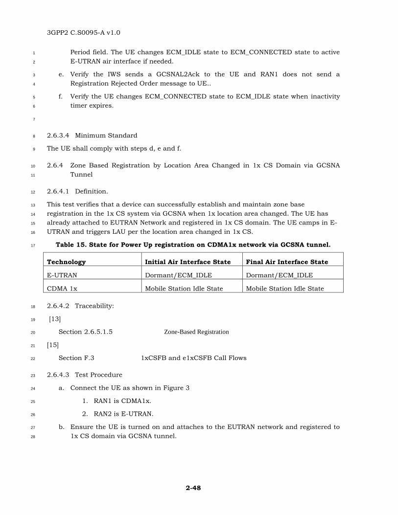
3GPP2 C.S0095-A v1.0
2-48
Period field. The UE changes ECM_IDLE state to ECM_CONNECTED state to active 1
E-UTRAN air interface if needed. 2
e. Verify the IWS sends a GCSNAL2Ack to the UE and RAN1 does not send a 3
Registration Rejected Order message to UE.. 4
f. Verify the UE changes ECM_CONNECTED state to ECM_IDLE state when inactivity 5
timer expires. 6
7
2.6.3.4 Minimum Standard 8
The UE shall comply with steps d, e and f. 9
2.6.4 Zone Based Registration by Location Area Changed in 1x CS Domain via GCSNA 10
Tunnel 11
2.6.4.1 Definition. 12
This test verifies that a device can successfully establish and maintain zone base 13
registration in the 1x CS system via GCSNA when 1x location area changed. The UE has 14
already attached to EUTRAN Network and registered in 1x CS domain. The UE camps in E-15
UTRAN and triggers LAU per the location area changed in 1x CS. 16
Table 15. State for Power Up registration on CDMA1x network via GCSNA tunnel. 17
Technology Initial Air Interface State Final Air Interface State
E-UTRAN Dormant/ECM_IDLE Dormant/ECM_IDLE
CDMA 1x Mobile Station Idle State Mobile Station Idle State
2.6.4.2 Traceability: 18
[13] 19
Section 2.6.5.1.5 Zone-Based Registration 20
[15] 21
Section F.3 1xCSFB and e1xCSFB Call Flows 22
2.6.4.3 Test Procedure 23
a. Connect the UE as shown in Figure 3 24
1. RAN1 is CDMA1x. 25
2. RAN2 is E-UTRAN. 26
b. Ensure the UE is turned on and attaches to the EUTRAN network and registered to 27
1x CS domain via GCSNA tunnel. 28
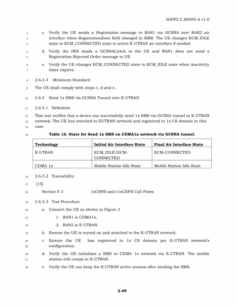
3GPP2 C.S0095-A v1.0
2-49
c. Verify the UE sends a Registration message to RAN1 via GCSNA over RAN2 air 1
interface when RegistrationZone field changed in SIB8. The UE changes ECM_IDLE 2
state to ECM_CONNECTED state to active E-UTRAN air interface if needed. 3
d. Verify the IWS sends a GCSNAL2Ack to the UE and RAN1 does not send a 4
Registration Rejected Order message to UE. 5
e. Verify the UE changes ECM_CONNECTED state to ECM_IDLE state when inacitivity 6
timer expires. 7
2.6.4.4 Minimum Standard 8
The UE shall comply with steps c, d and e. 9
2.6.5 Send 1x SMS via GCSNA Tunnel over E-UTRAN 10
2.6.5.1 Definition 11
This test verifies that a device can successfully send 1x SMS via GCSNA tunnel in E-UTRAN 12
network. The UE has attached to EUTRAN network and registered to 1x CS domain in this 13
case. 14
Table 16. State for Send 1x SMS on CDMA1x network via GCSNA tunnel. 15
Technology Initial Air Interface State Final Air Interface State
E-UTRAN ECM_IDLE/ECM-
CONNECTED
ECM-CONNECTED
CDMA 1x Mobile Station Idle State Mobile Station Idle State
2.6.5.2 Traceability: 16
[15] 17
Section F.3 1xCSFB and e1xCSFB Call Flows 18
2.6.5.3 Test Procedure 19
a. Connect the UE as shown in Figure 3 20
1. RAN1 is CDMA1x. 21
2. RAN2 is E-UTRAN. 22
b. Ensure the UE is turned on and attached to the E-UTRAN network. 23
c. Ensure the UE has registered to 1x CS domain per E-UTRAN network’s 24
configuration. 25
d. Verify the UE initializes a SMS to CDMA 1x network via E-UTRAN. The mobile 26
station still camps in E-UTRAN. 27
e. Verify the UE can keep the E-UTRAN active session after sending the SMS. 28
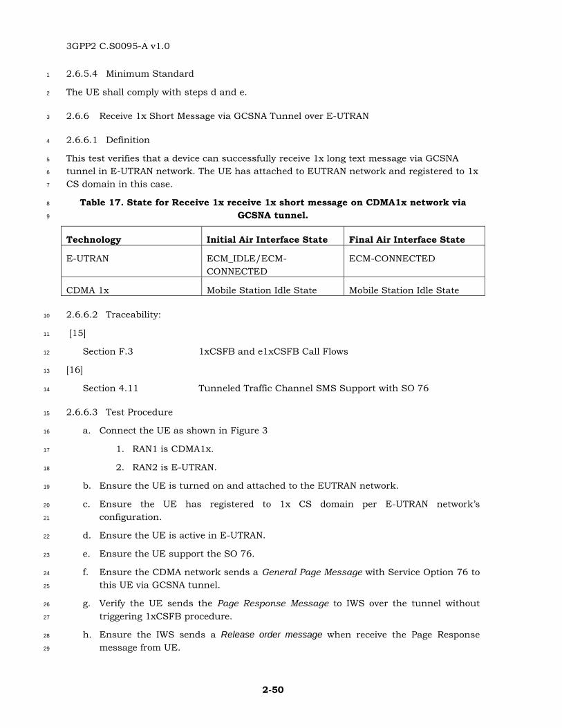
3GPP2 C.S0095-A v1.0
2-50
2.6.5.4 Minimum Standard 1
The UE shall comply with steps d and e. 2
2.6.6 Receive 1x Short Message via GCSNA Tunnel over E-UTRAN 3
2.6.6.1 Definition 4
This test verifies that a device can successfully receive 1x long text message via GCSNA 5
tunnel in E-UTRAN network. The UE has attached to EUTRAN network and registered to 1x 6
CS domain in this case. 7
Table 17. State for Receive 1x receive 1x short message on CDMA1x network via 8
GCSNA tunnel. 9
Technology Initial Air Interface State Final Air Interface State
E-UTRAN ECM_IDLE/ECM-
CONNECTED
ECM-CONNECTED
CDMA 1x Mobile Station Idle State Mobile Station Idle State
2.6.6.2 Traceability: 10
[15] 11
Section F.3 1xCSFB and e1xCSFB Call Flows 12
[16] 13
Section 4.11 Tunneled Traffic Channel SMS Support with SO 76 14
2.6.6.3 Test Procedure 15
a. Connect the UE as shown in Figure 3 16
1. RAN1 is CDMA1x. 17
2. RAN2 is E-UTRAN. 18
b. Ensure the UE is turned on and attached to the EUTRAN network. 19
c. Ensure the UE has registered to 1x CS domain per E-UTRAN network’s 20
configuration. 21
d. Ensure the UE is active in E-UTRAN. 22
e. Ensure the UE support the SO 76. 23
f. Ensure the CDMA network sends a General Page Message with Service Option 76 to 24
this UE via GCSNA tunnel. 25
g. Verify the UE sends the Page Response Message to IWS over the tunnel without 26
triggering 1xCSFB procedure. 27
h. Ensure the IWS sends a Release order message when receive the Page Response 28
message from UE. 29
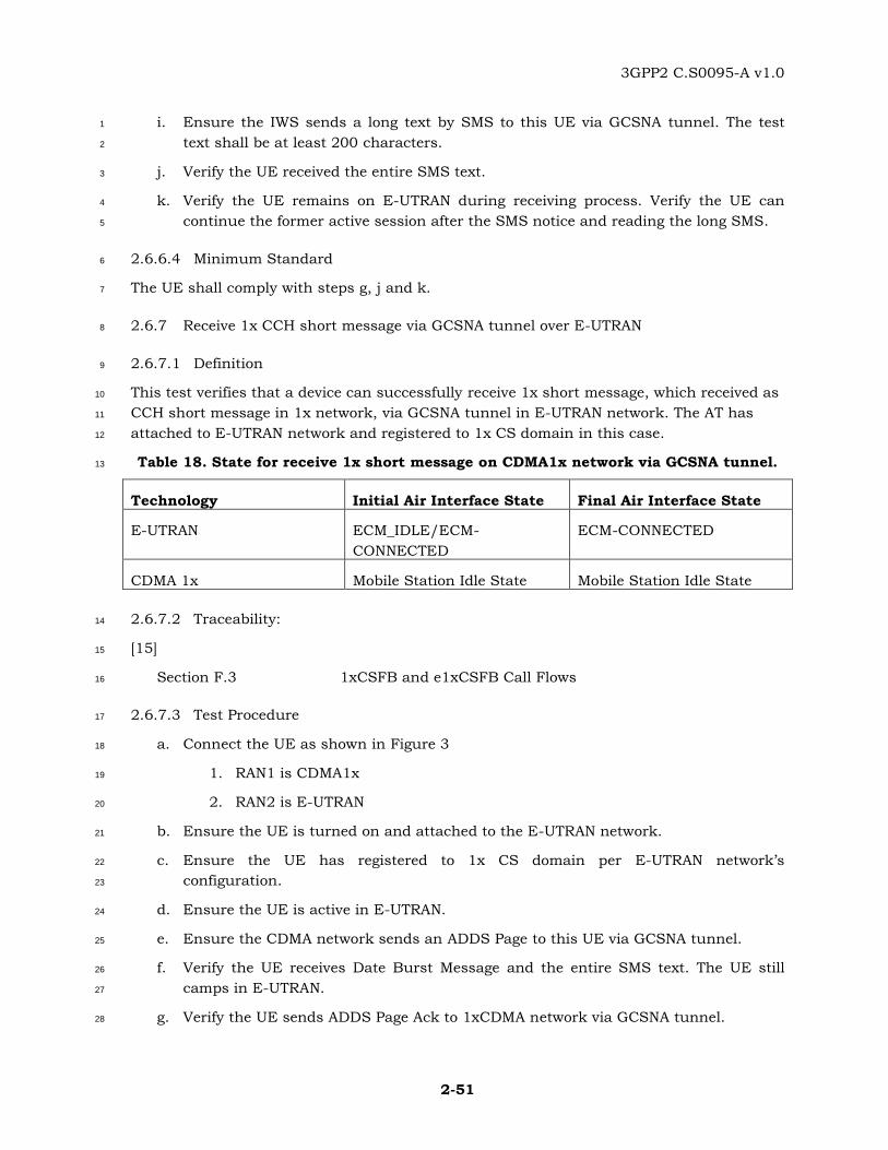
3GPP2 C.S0095-A v1.0
2-51
i. Ensure the IWS sends a long text by SMS to this UE via GCSNA tunnel. The test 1
text shall be at least 200 characters. 2
j. Verify the UE received the entire SMS text. 3
k. Verify the UE remains on E-UTRAN during receiving process. Verify the UE can 4
continue the former active session after the SMS notice and reading the long SMS. 5
2.6.6.4 Minimum Standard 6
The UE shall comply with steps g, j and k. 7
2.6.7 Receive 1x CCH short message via GCSNA tunnel over E-UTRAN 8
2.6.7.1 Definition 9
This test verifies that a device can successfully receive 1x short message, which received as 10
CCH short message in 1x network, via GCSNA tunnel in E-UTRAN network. The AT has 11
attached to E-UTRAN network and registered to 1x CS domain in this case. 12
Table 18. State for receive 1x short message on CDMA1x network via GCSNA tunnel. 13
Technology Initial Air Interface State Final Air Interface State
E-UTRAN ECM_IDLE/ECM-
CONNECTED
ECM-CONNECTED
CDMA 1x Mobile Station Idle State Mobile Station Idle State
2.6.7.2 Traceability: 14
[15] 15
Section F.3 1xCSFB and e1xCSFB Call Flows 16
2.6.7.3 Test Procedure 17
a. Connect the UE as shown in Figure 3 18
1. RAN1 is CDMA1x 19
2. RAN2 is E-UTRAN 20
b. Ensure the UE is turned on and attached to the E-UTRAN network. 21
c. Ensure the UE has registered to 1x CS domain per E-UTRAN network’s 22
configuration. 23
d. Ensure the UE is active in E-UTRAN. 24
e. Ensure the CDMA network sends an ADDS Page to this UE via GCSNA tunnel. 25
f. Verify the UE receives Date Burst Message and the entire SMS text. The UE still 26
camps in E-UTRAN. 27
g. Verify the UE sends ADDS Page Ack to 1xCDMA network via GCSNA tunnel. 28
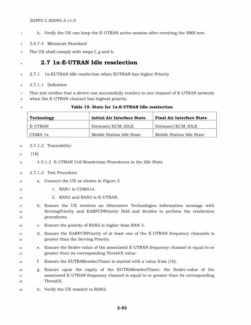
3GPP2 C.S0095-A v1.0
2-52
h. Verify the UE can keep the E-UTRAN active session after receiving the SMS text. 1
2.6.7.4 Minimum Standard 2
The UE shall comply with steps f, g and h. 3
2.7 1x-E-UTRAN Idle reselection 4
2.7.1 1x-EUTRAN Idle reselection when EUTRAN has higher Priority 5
2.7.1.1 Definition 6
This test verifies that a device can successfully reselect to one channel of E-UTRAN network 7
when the E-UTRAN channel has highest priority. 8
Table 19. State for 1x-E-UTRAN Idle reselection 9
Technology Initial Air Interface State Final Air Interface State
E-UTRAN Dormant/ECM_IDLE Dormant/ECM_IDLE
CDMA 1x Mobile Station Idle State Mobile Station Idle State
2.7.1.2 Traceability: 10
[16] 11
4.5.1.2 E-UTRAN Cell Reselection Procedures in the Idle State 12
2.7.1.3 Test Procedure 13
a. Connect the UE as shown in Figure 3 14
1. RAN1 is CDMA1x. 15
2. RAN2 and RAN3 is E-UTRAN. 16
b. Ensure the UE receives an Alternative Technologies Information message with 17
ServingPriority and EARFCNPriority field and decides to perform the reselection 18
procedures. 19
c. Ensure the priority of RAN2 is higher than RAN 3. 20
d. Ensure the EARFCNPriority of at least one of the E-UTRAN frequency channels is 21
greater than the Serving Priority. 22
e. Ensure the Srxlev-value of the associated E-UTRAN frequency channel is equal to or 23
greater than its corresponding ThreshX value. 24
f. Ensure the EUTRAReselectTimer is started with a value from [16]. 25
g. Ensure upon the expiry of the EUTRAReselectTimer, the Srxlev-value of the 26
associated E-UTRAN frequency channel is equal to or greater than its corresponding 27
ThreshX. 28
h. Verify the UE reselect to RAN2. 29
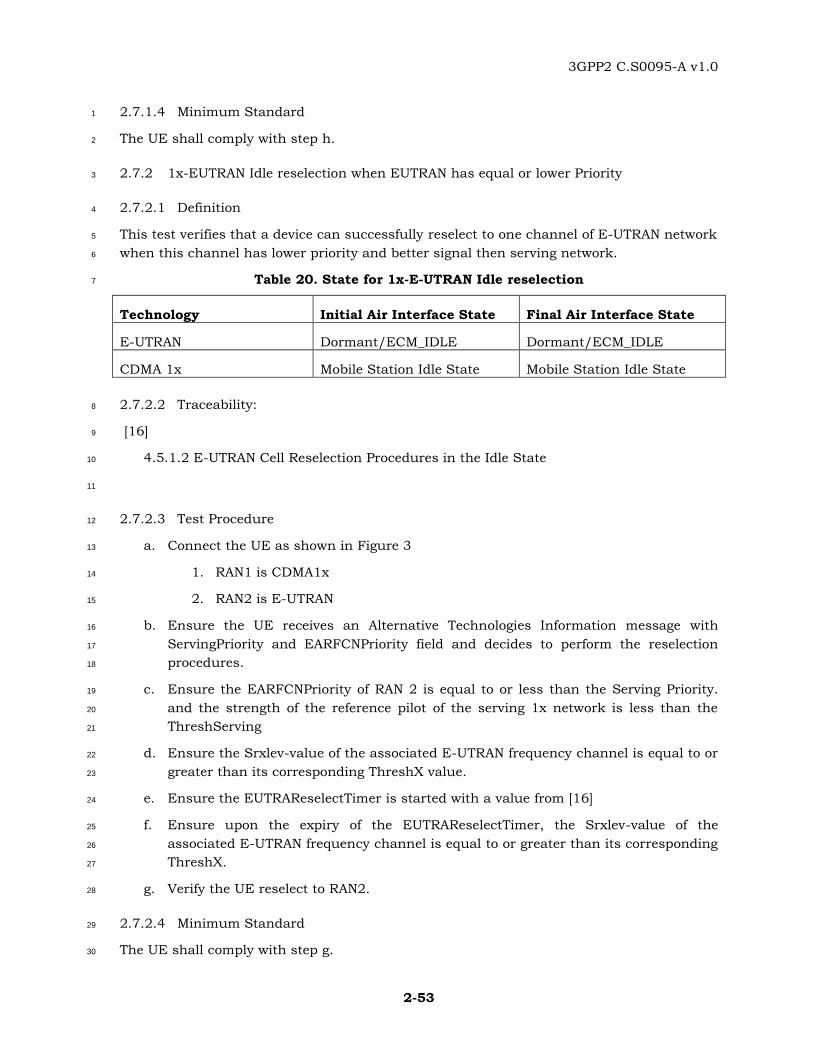
3GPP2 C.S0095-A v1.0
2-53
2.7.1.4 Minimum Standard 1
The UE shall comply with step h. 2
2.7.2 1x-EUTRAN Idle reselection when EUTRAN has equal or lower Priority 3
2.7.2.1 Definition 4
This test verifies that a device can successfully reselect to one channel of E-UTRAN network 5
when this channel has lower priority and better signal then serving network. 6
Table 20. State for 1x-E-UTRAN Idle reselection 7
Technology Initial Air Interface State Final Air Interface State
E-UTRAN Dormant/ECM_IDLE Dormant/ECM_IDLE
CDMA 1x Mobile Station Idle State Mobile Station Idle State
2.7.2.2 Traceability: 8
[16] 9
4.5.1.2 E-UTRAN Cell Reselection Procedures in the Idle State 10
11
2.7.2.3 Test Procedure 12
a. Connect the UE as shown in Figure 3 13
1. RAN1 is CDMA1x 14
2. RAN2 is E-UTRAN 15
b. Ensure the UE receives an Alternative Technologies Information message with 16
ServingPriority and EARFCNPriority field and decides to perform the reselection 17
procedures. 18
c. Ensure the EARFCNPriority of RAN 2 is equal to or less than the Serving Priority. 19
and the strength of the reference pilot of the serving 1x network is less than the 20
ThreshServing 21
d. Ensure the Srxlev-value of the associated E-UTRAN frequency channel is equal to or 22
greater than its corresponding ThreshX value. 23
e. Ensure the EUTRAReselectTimer is started with a value from [16] 24
f. Ensure upon the expiry of the EUTRAReselectTimer, the Srxlev-value of the 25
associated E-UTRAN frequency channel is equal to or greater than its corresponding 26
ThreshX. 27
g. Verify the UE reselect to RAN2. 28
2.7.2.4 Minimum Standard 29
The UE shall comply with step g. 30
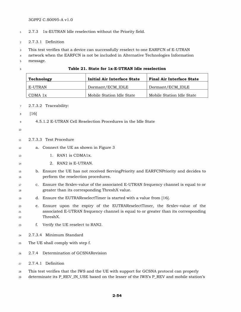
3GPP2 C.S0095-A v1.0
2-54
2.7.3 1x-EUTRAN Idle reselection without the Priority field. 1
2.7.3.1 Definition 2
This test verifies that a device can successfully reselect to one EARFCN of E-UTRAN 3
network when the EARFCN is not be included in Alternative Technologies Information 4
message. 5
Table 21. State for 1x-E-UTRAN Idle reselection 6
Technology Initial Air Interface State Final Air Interface State
E-UTRAN Dormant/ECM_IDLE Dormant/ECM_IDLE
CDMA 1x Mobile Station Idle State Mobile Station Idle State
2.7.3.2 Traceability: 7
[16] 8
4.5.1.2 E-UTRAN Cell Reselection Procedures in the Idle State 9
10
2.7.3.3 Test Procedure 11
a. Connect the UE as shown in Figure 3 12
1. RAN1 is CDMA1x. 13
2. RAN2 is E-UTRAN. 14
b. Ensure the UE has not received ServingPriority and EARFCNPriority and decides to 15
perform the reselection procedures. 16
c. Ensure the Srxlev-value of the associated E-UTRAN frequency channel is equal to or 17
greater than its corresponding ThreshX value. 18
d. Ensure the EUTRAReselectTimer is started with a value from [16]. 19
e. Ensure upon the expiry of the EUTRAReselectTimer, the Srxlev-value of the 20
associated E-UTRAN frequency channel is equal to or greater than its corresponding 21
ThreshX. 22
f. Verify the UE reselect to RAN2. 23
2.7.3.4 Minimum Standard 24
The UE shall comply with step f. 25
2.7.4 Determination of GCSNARevision 26
2.7.4.1 Definition 27
This test verifies that the IWS and the UE with support for GCSNA protocol can properly 28
determinate its P_REV_IN_USE based on the lesser of the IWS’s P_REV and mobile station’s 29
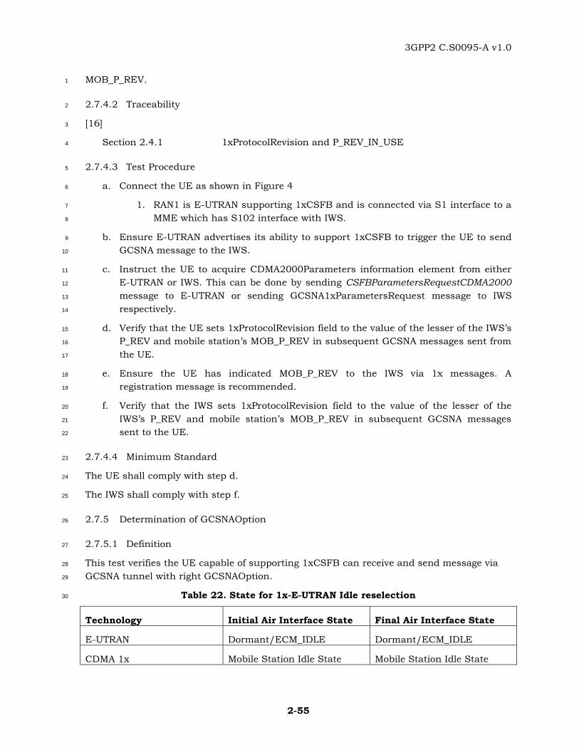
3GPP2 C.S0095-A v1.0
2-55
MOB_P_REV. 1
2.7.4.2 Traceability 2
[16] 3
Section 2.4.1 1xProtocolRevision and P_REV_IN_USE 4
2.7.4.3 Test Procedure 5
a. Connect the UE as shown in Figure 4 6
1. RAN1 is E-UTRAN supporting 1xCSFB and is connected via S1 interface to a 7
MME which has S102 interface with IWS. 8
b. Ensure E-UTRAN advertises its ability to support 1xCSFB to trigger the UE to send 9
GCSNA message to the IWS. 10
c. Instruct the UE to acquire CDMA2000Parameters information element from either 11
E-UTRAN or IWS. This can be done by sending CSFBParametersRequestCDMA2000 12
message to E-UTRAN or sending GCSNA1xParametersRequest message to IWS 13
respectively. 14
d. Verify that the UE sets 1xProtocolRevision field to the value of the lesser of the IWS’s 15
P_REV and mobile station’s MOB_P_REV in subsequent GCSNA messages sent from 16
the UE. 17
e. Ensure the UE has indicated MOB_P_REV to the IWS via 1x messages. A 18
registration message is recommended. 19
f. Verify that the IWS sets 1xProtocolRevision field to the value of the lesser of the 20
IWS’s P_REV and mobile station’s MOB_P_REV in subsequent GCSNA messages 21
sent to the UE. 22
2.7.4.4 Minimum Standard 23
The UE shall comply with step d. 24
The IWS shall comply with step f. 25
2.7.5 Determination of GCSNAOption 26
2.7.5.1 Definition 27
This test verifies the UE capable of supporting 1xCSFB can receive and send message via 28
GCSNA tunnel with right GCSNAOption. 29
Table 22. State for 1x-E-UTRAN Idle reselection 30
Technology Initial Air Interface State Final Air Interface State
E-UTRAN Dormant/ECM_IDLE Dormant/ECM_IDLE
CDMA 1x Mobile Station Idle State Mobile Station Idle State
3GPP2 C.S0095-A v1.0
2-56
2.7.5.2 Traceability: 1
[8] 2
14 GCSNA REVISIONS 3
[16] 4
2.2 Mobile Station Procedures 5
2.3 IWS Procedures 6
2.7.5.3 Test Procedure 7
a. Connect the UE as shown in Figure 4 8
1. RAN1 is E-UTRAN capable of supporting 1xCSFB and is connected via S1 9
interface to a MME which has S102 interface with IWS. The IWS should 10
support and prefer GCSNAOption A1. The UE should support and prefer 11
GCSNAOption A. 12
b. Ensure E-UTRAN advertises its ability to support 1xCSFB to trigger the UE to send 13
a message to the IWS. A registration message is recommended. 14
c. Verify the UE sends the message with GCSNAOption A via tunnel. 15
d. Verify the IWS sends a message to UE with GCSNAOption A. A Registration 16
Accepted Order is recommended. 17
e. Verify the UE can decode this message from IWS successfully. 18
2.7.5.4 Minimum Standard 19
The UE shall comply with step cande. 20
IWS shall comply with stepd. 21
2.8 UE handle GCSNA message in LTE network 22
2.8.1 Introduction 23
Tests included in this section verify UE is able to process received GCSNA message sent by 24
GCSNA tunnel. 25
2.8.2 Transmission and Reception of 1x messages 26
2.8.2.1 Definition 27
This test verifies that a device can successfully process message(s) which is included in 28
GCSNACircuitService message. 29
1 GCSNAOption A is one pair of GCSNAClass and GCSNAClassRevision from reference [8].
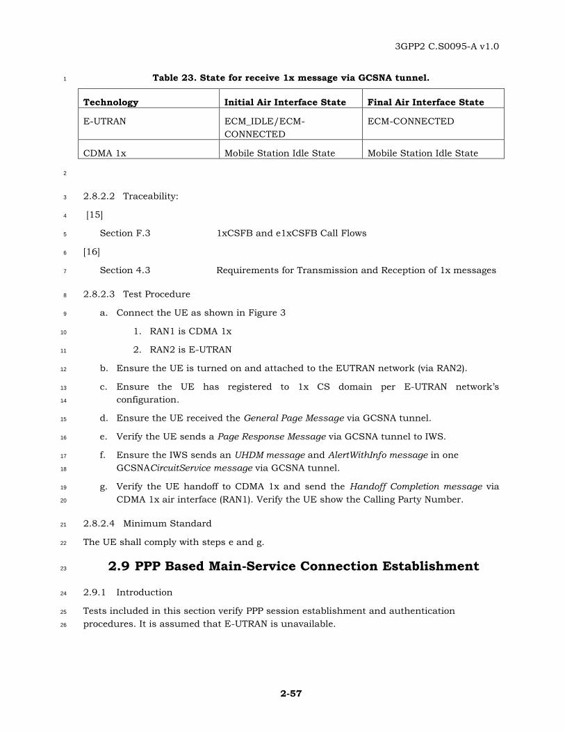
3GPP2 C.S0095-A v1.0
2-57
Table 23. State for receive 1x message via GCSNA tunnel. 1
Technology Initial Air Interface State Final Air Interface State
E-UTRAN ECM_IDLE/ECM-
CONNECTED
ECM-CONNECTED
CDMA 1x Mobile Station Idle State Mobile Station Idle State
2
2.8.2.2 Traceability: 3
[15] 4
Section F.3 1xCSFB and e1xCSFB Call Flows 5
[16] 6
Section 4.3 Requirements for Transmission and Reception of 1x messages 7
2.8.2.3 Test Procedure 8
a. Connect the UE as shown in Figure 3 9
1. RAN1 is CDMA 1x 10
2. RAN2 is E-UTRAN 11
b. Ensure the UE is turned on and attached to the EUTRAN network (via RAN2). 12
c. Ensure the UE has registered to 1x CS domain per E-UTRAN network’s 13
configuration. 14
d. Ensure the UE received the General Page Message via GCSNA tunnel. 15
e. Verify the UE sends a Page Response Message via GCSNA tunnel to IWS. 16
f. Ensure the IWS sends an UHDM message and AlertWithInfo message in one 17
GCSNACircuitService message via GCSNA tunnel. 18
g. Verify the UE handoff to CDMA 1x and send the Handoff Completion message via 19
CDMA 1x air interface (RAN1). Verify the UE show the Calling Party Number. 20
2.8.2.4 Minimum Standard 21
The UE shall comply with steps e and g. 22
2.9 PPP Based Main-Service Connection Establishment 23
2.9.1 Introduction 24
Tests included in this section verify PPP session establishment and authentication 25
procedures. It is assumed that E-UTRAN is unavailable. 26
3GPP2 C.S0095-A v1.0
2-58
2.9.2 EAP AKA’ Authentication during Initial PPP session establishment 1
2.9.2.1 Definition 2
This test verifies that EAP is successfully negotiated as the authentication protocol and 3
EAP-AKA’ authentication is successful during PPP session establishment in eHRPD. 4
2.9.2.2 Traceability: 5
[3] 6
Section 2.1 Definitions 7
Section 4.2.1 EAP Protocol Negotiation 8
Section 4.2.2.1 UE Identity Management 9
Section 4.2.2.2 UE Network Access Authentication 10
Section 9.1.1 Establishment of a Main Service Connection 11
Section 9.1.3 PPP-Based Main Service Connection 12
2.9.2.3 Test Procedure 13
a. Ensure that eHRPD system is available to the AT and E-UTRAN system is 14
unavailable to the AT. 15
b. Ensure that the AT is in inactive/NULL state, i.e. no PPP session exists between the 16
AT and the HSGW. 17
c. Ensure that the AT establishes an eHRPD session with the AN, i.e. the AT has 18
accepted a value of 0x07 for the ProtocolID field of 19
FlowNNFlowProtocolParametersFwd and FlowNNFlowProtocolParametersRev 20
attributes of the EMPA Link Flow bound to ReservationLabel 0xFF. 21
d. Cause the AT to start the PPP session establishment. This can be triggered by 22
starting an application that requires data transmission by the AT. 23
e. Verify that the AT sends a LCP-Configure-Request message to the HSGW. 24
f. Ensure that the HSGW sends a LCP-Configure-Ack message to the AT. 25
g. Ensure that the HSGW sends a LCP-Configure-Request message with 26
Authentication-Protocol option set to C227 (EAP). 27
h. Verify that the AT sends a LCP-Configure-Ack message to the HSGW and accepts 28
EAP based authentication. 29
i. Instruct the HSGW to send an EAP Request/Identity to the AT. 30
j. Verify that the AT sends an EAP Response / Identity with Identity=’IMSI-NAI’ to the 31
HSGW. 32
k. Ensure that the HSGW sends an EAP-Request/AKA’-Challenge to the AT. Ensure 33
that the AMF separation bit is set to 1 and that other fields such as AUTN are set 34
correctly. 35
3GPP2 C.S0095-A v1.0
2-59
l. Verify that the AT sends an EAP-Response/AKA’-Challenge carrying the MAC and 1
the RES fields. 2
m. If the AT receives an EAP-Request/AKA’-Notification message from the HSGW, verify 3
that the AT sends an EAP-Response/AKA’-Notification message to the HSGW. Verify 4
that the fields included in the EAP-Response/AKA’-Challenge are correct. This can 5
be verified if the HSGW sends an EAP-Success to the AT. 6
2.9.2.4 Minimum Standard 7
The AT shall comply with steps e, h, j, l, and m. 8
2.9.3 EAP AKA’ Authentication Failure during Initial PPP session establishment (Incorrect 9
AUTN) 10
2.9.3.1 Definition 11
This test verifies AT behavior when EAP AKA’ authentication failure occurs during PPP 12
session negotiation in eHRPD establishment. 13
2.9.3.2 Traceability: 14
[3] 15
Section 2.1 Definitions 16
Section 4.2.1 EAP Protocol Negotiation 17
Section 4.2.2.1 UE Identity Management 18
Section 4.2.2.2 UE Network Access Authentication 19
Section 10.1.1 Establishment of a Main-Service Connection 20
Section 10.1.3 PPP Based Main-Service Connection 21
2.9.3.3 Test Procedure 22
a. Ensure that eHRPD system is available to the AT and E-UTRAN system is 23
unavailable to the AT. 24
b. Ensure that the AT is in inactive/NULL state, i.e. no PPP session exists between the 25
AT and the HSGW. 26
c. Ensure that the AT establishes an eHRPD session with the AN, i.e. the AT has 27
accepted a value of 0x07 for the ProtocolID field of 28
FlowNNFlowProtocolParametersFwd and FlowNNFlowProtocolParametersRev 29
attributes of the EMPA Link Flow bound to ReservationLabel 0xFF. 30
d. Cause the AT to start the PPP session establishment. This can be triggered by 31
starting an application that requires data transmission by the AT. 32
e. Ensure that the AT sends a LCP-Configure-Request message to the HSGW. 33
f. Ensure that the HSGW sends a LCP-Configure-Ack message to the AT. 34

3GPP2 C.S0095-A v1.0
2-60
g. Ensure that the HSGW sends a LCP-Configure-Request message with 1
Authentication-Protocol option set to C227 (EAP). 2
h. Ensure that the AT sends a LCP-Configure-Ack message to the HSGW and accept 3
EAP based authentication. 4
i. Instruct the HSGW to send an EAP-Request/AKA’-Challenge to the AT with AUTN 5
field set incorrectly. 6
j. Verify that the AT sends an EAP-Response/AKA-Authentication-Reject to the 7
HSGW. 8
k. Ensure that the HSGW sends an EAP-Failure to the AT. 9
l. Verify that the AT sends a LCP-Term-Request to the HSGW. 10
m. If the AT supports cdma2000 1x and cdma2000 1x system is available, the 11
subsequent call may be placed over cdma2000 1x system. Note that this behavior is 12
implementation dependent. 13
n. If the AT and the RAN support HRPD, the subsequent call may be placed over HRPD 14
system. Note that this behavior is implementation dependent. For example, HRPD 15
based personality may be negotiated or a new HRPD session may be negotiated. 16
o. If the AT supports fallback to cdma2000 1x or HRPD, verify that the AT obtains an 17
IP address from the PDSN and is able to send and receive best effort data. 18
2.9.3.4 Minimum Standard 19
The AT shall comply with steps j and l. 20
The AT should comply with step o. 21
2.10 IP Address Assignment and PDN Attach and Detach 22
Procedures 23
2.10.1 Introduction 24
This section contains tests for IP address assignment and PDN attach and Detach 25
procedures. 26
2.10.2 IPv4 address assignment through VSNCP 27
2.10.2.1 Definition 28
This test verifies that the AT can use VSNCP to obtain an IPv4 address from the eHRPD 29
HSGW. The test is applicable to ATs that support IPv4. 30
2.10.2.2 Traceability: 31
[3] 32
Section 4.4.6.1 IPv4 Address Allocation during PDN Connection 33
Establishment 34

3GPP2 C.S0095-A v1.0
2-61
Section 4.4.6.4 IPv6 Address Allocation 1
Section 9.1.4.1 3GPP2 VSNCP Configuration Options 2
Section 9.1.4.2 3GPP2 VSNCP Configure-Request 3
Section 9.1.4.3 3GPP2 VSNCP Configure-Ack 4
Section 9.1.4.6 3GPP2 VSNCP Terminate-Request 5
Section 9.1.4.7 3GPP2 VSNCP Terminate-Ack 6
2.10.2.3 Test Procedure 7
a. Ensure that eHRPD system is available to the AT and E-UTRAN system is 8
unavailable to the AT. 9
b. Configure the HSGW to disable the DHCP support and the PDN-GW to assign IPv4 10
address. 11
c. Ensure that the AT does not have an IPv4 address assigned from the network. Note, 12
this step may require HSGW to send a PPP VSNCP Terminate-Request. 13
d. If the AT has an open session with the RAN, instruct the RAN to send a 14
SessionClose message to the AT and ensure that the AT sends a SessionClose 15
message to the RAN. 16
e. Ensure that the AT has eHRPD IMSI and credentials (authentication keys) 17
provisioned. 18
f. Cause the AT to negotiate a new eHRPD session with the RAN and ensure that the 19
session negotiation is successful. 20
g. Cause the AT to start the PPP session establishment. This can be triggered by 21
starting an application that requires data transmission by the AT. 22
h. Ensure that the AT has been successfully authenticated and the HSGW sends an 23
EAP-Success message to the AT. 24
i. Verify that the AT sends PPP: VSNCP-Configure-Request message containing the 25
following fields: 26
1) PDN Address = 0 27
2) IPv4 Default Router Address= 0.0.0.0 28
3) Attach Type = Initial 29
4) PDN-ID 30
5) PDN type = 1 or 3. 31
j. Ensure that the HSGW sends a PPP: VSNCP-Configure-Ack message to the AT 32
containing the IPv4 address and the PDN-ID. 33
k. Ensure that the HSGW sends a PPP: VSNCP-Configure-Request message containing 34
the PDN-ID to the AT. 35

3GPP2 C.S0095-A v1.0
2-62
l. Verify that the AT sends a VSNCP-Configure-Ack message containing the PDN-ID to 1
the HSGW. 2
m. Verify that the AT can send and receive data for the assigned IPv4 address using the 3
PDN-ID used by the AT in step i. 4
2.10.2.4 Minimum Standard 5
The AT shall comply with steps i, l, and m. 6
2.10.3 IPv6 address assignment through VSNCP 7
2.10.3.1 Definition 8
This test verifies that the AT can use VSNCP to obtain an IPv6 address from the eHRPD 9
HSGW. The test is applicable to ATs that support IPv6. 10
2.10.3.2 Traceability: 11
[3] 12
Section 4.4.1.1.1 IP Address Allocation: VSNCP Configure-Request 13
Section 4.4.1.1.4 IP Address Allocation: VSNCP Configure-Ack 14
Section 4.4.6.1 IPv4 Address Allocation during PDN Connection 15
Establishment 16
Section 4.4.6.4 IPv6 Address Allocation 17
Section 9.1.4.1 3GPP2 VSNCP Configuration Options 18
Section 9.1.4.2 3GPP2 VSNCP Configure-Request 19
Section 9.1.4.3 3GPP2 VSNCP Configure-Ack 20
Section 9.1.4.6 3GPP2 VSNCP Terminate-Request 21
Section 9.1.4.7 3GPP2 VSNCP Terminate-Ack 22
2.10.3.3 Test Procedure 23
a. Ensure that eHRPD system is available to the AT and E-UTRAN system is 24
unavailable to the AT. 25
b. Configure the PDN-GW to assign IPv6 address and disable DHCP support at the 26
HSGW. 27
c. Ensure that Router Advertisement broadcast is disabled at the HSGW. Note, if step 28
n, is not supported, the test should be repeated with Router Advertisement 29
broadcast is enabled at the HSGW. 30
d. Ensure that the AT does not have an IPv6 address assigned from the network. Note, 31
this step may require HSGW to send a PPP VSNCP Terminate-Request. 32
3GPP2 C.S0095-A v1.0
2-63
e. If the AT has an open session with the RAN, instruct the RAN to send a 1
SessionClose message to the AT and ensure that the AT sends a SessionClose 2
message to the RAN. 3
f. Ensure that the AT has eHRPD IMSI and credentials (authentication keys) 4
provisioned. 5
g. Cause the AT to negotiate a new eHRPD session with the RAN and ensure that the 6
session negotiation is successful. 7
h. Cause the AT to start the PPP session establishment. This can be triggered by 8
starting an application that requires data transmission by the AT. 9
i. Ensure that the AT has been successfully authenticated and the HSGW sends an 10
EAP-Success message to the AT. 11
j. Verify that the AT sends PPP: VSNCP-Configure-Request message containing the 12
following fields: 13
1. PDN Address = 0 14
2. Attach Type = Initial 15
3. PDN-ID 16
4. PDN type = 2 or 3. 17
k. Ensure that the HSGW sends a PPP: VSNCP-Configure-Ack message to the AT 18
containing the IPv6 Interface Identifier in the PDN address field and the PDN-ID. 19
l. Ensure that the HSGW sends a PPP: VSNCP-Configure-Request message containing 20
the PDN-ID to the AT. 21
m. Verify that the AT sends a VSNCP-Configure-Ack message containing the PDN-ID to 22
the HSGW. 23
n. If the AT does not receive Router Advertisement message from the HSGW, verify that 24
the AT sends a Router Solicitation message to the HSGW. 25
o. Ensure that the HSGW sends a Router Advertisement message containing the IPv6 26
home network prefix. 27
p. Verify that the AT can send and receive data for the assigned Ipv6 address using the 28
PDN-ID used by the AT in step j. 29
2.10.3.4 Minimum Standard 30
The AT shall comply with steps j, m, and p. 31
AT should comply with steps n. 32
2.10.4 HSGW initiated PDN release through VSNCP 33
2.10.4.1 Definition 34
This test verifies that the AT supports PDN detach procedures through VSNCP, when the 35
3GPP2 C.S0095-A v1.0
2-64
HSGW initiates these procedures. 1
2.10.4.2 Traceability: 2
[3] 3
Section 4.4.6.1 IPv4 Address Allocation during PDN Connection 4
Establishment 5
Section 4.4.6.4 IPv6 Address Allocation 6
Section 10.2 Network Initiated UE Detach 7
Section 10.3 Network Initiated PDN Disconnection 8
Section 9.1.4.2 3GPP2 VSNCP Configure-Request 9
Section 9.1.4.3 3GPP2 VSNCP Configure-Ack 10
Section 9.1.4.6 3GPP2 VSNCP Terminate-Request 11
Section 9.1.4.7 3GPP2 VSNCP Terminate-Ack 12
2.10.4.3 Test Procedure 13
a. Ensure that the AT can send and receive data on assigned IPv4/IPv6 address 14
received from a PDN. 15
b. Ensure that the AT is transmitting data for the PDN in step a. 16
c. Cause the HSGW to send a VSNCP Terminate Request containing the PDN-ID for 17
the PDN used in step a. 18
d. Verify that the AT sends a VSNCP Terminate Ack message containing the PDN-ID. 19
e. Verify that the AT stops transmitting data with the PDN-ID used in step c. 20
f. If the AT supports IPv4v6 repeat the test with the following changes: 21
1. In step a, ensure that the AT receives a dual IP address assignment from 22
the PDN-GW. 23
2. In step b, ensure that the AT is sending data using IPv4 and IPv6 addresses 24
assigned by the PDN-GW. 25
3. In step e, verify that the AT stops sending data using IPv4 address and IPv6 26
address assigned by the PDN-GW. 27
2.10.4.4 Minimum Standard 28
The AT shall comply with steps d and e. 29
2.10.5 Access Terminal initiated PDN release through VSNCP 30
2.10.5.1 Definition 31
This test verifies that the AT supports PDN detach procedures through VSNCP or LCP, 32
when the AT initiates these procedures. 33
3GPP2 C.S0095-A v1.0
2-65
2.10.5.2 Traceability: 1
[3] 2
Section 4.4.6.1 IPv4 Address Allocation during PDN Connection 3
Establishment 4
Section 4.4.6.4 IPv6 Address Allocation 5
Section 10.1 UE Initiated Release procedures 6
Section 9.1.4.2 3GPP2 VSNCP Configure-Request 7
Section 9.1.4.3 3GPP2 VSNCP Configure-Ack 8
Section 9.1.4.6 3GPP2 VSNCP Terminate-Request 9
Section 9.1.4.7 3GPP2 VSNCP Terminate-Ack 10
2.10.5.3 Test Procedure 11
a. Cause the AT to establish connection with two PDN-GWs (PDN-GW1 and PDN-12
GW2). If the AT supports IPv4 and IPv6, PDN-GW2 should assign IPv4 and IPv6 13
address to the AT. 14
b. Ensure that the AT can send and receive data on assigned IPv4/IPv6 addresses 15
using PDN-IDs for PDN-GW1 and PDN-GW2. 16
c. Cause the AT to send a VSNCP Terminate Request containing the PDN-ID of PDN-17
GW1. Note this can be triggered by closing all the applications using the PDN-GW1. 18
d. Ensure that the network sends a VSNCP Terminate Ack message containing the 19
PDN-ID of PDN-GW1. 20
e. Cause the AT to send a VSNCP Terminate Request containing the PDN-ID of PDN-21
GW2 or an LCP-Term-Request. Note this can be triggered by closing all the 22
applications that are using the PDN-GW2. 23
f. Cause the AT to restart the applications that used PDN-GW1 and PDN-GW2 in step 24
a. 25
g. Verify that the AT sends a VSNCP Configure Request message requesting an IP 26
address from the PDN-GW1 and PDN-GW2. 27
2.10.5.4 Minimum Standard 28
The AT shall comply with step g. 29
2.10.6 Network Initiated PDN resynchronization VSNCP 30
2.10.6.1 Definition 31
This test verifies that the AT supports PDN resynchronization procedures through VSNCP, 32
when the network initiates these procedures. 33

3GPP2 C.S0095-A v1.0
2-66
2.10.6.2 Traceability: 1
[3] 2
Section 4.4.6.1 IPv4 Address Allocation during PDN Connection 3
Establishment 4
Section 4.4.6.4 IPv6 Address Allocation 5
Section 10.2 Network Initiated UE Detach 6
Section 10.3 Network Initiated PDN Disconnection 7
Section 9.1.4.2 3GPP2 VSNCP Configure-Request 8
Section 9.1.4.3 3GPP2 VSNCP Configure-Ack 9
Section 9.1.4.6 3GPP2 VSNCP Terminate-Request 10
Section 9.1.4.7 3GPP2 VSNCP Terminate-Ack 11
2.10.6.3 Test Procedure 12
a. Ensure that the AT can send and receive data using the assigned IPv4/IPv6 address 13
and using PDN-ID. 14
b. Ensure that the AT is transmitting data containing PDN-ID. 15
c. Cause the HSGW to send a VSNCP Configure Request containing the PDN-ID. 16
d. Verify that the AT sends a VSNCP Configure Request message containing the PDN-17
ID, APN, PDN Address, Protocol Configuration Options, and AttachType set to 18
Handover. 19
e. Ensure that the HSGW sends the VSNCP Configure Ack message containing the 20
PDN-ID, APN, PDN Address, Protocol Configuration Options, and Attach Type set to 21
Handover to the AT. The message may contain new parameters for the PDN 22
connection. 23
f. Verify that the AT sends VSNCP Configure Ack message containing the PDN-ID in 24
step e. 25
2.10.6.4 Minimum Standard 26
The AT shall comply with steps d and f. 27
2.10.7 PPP Renegotiation upon Inter-HSGW handoff 28
2.10.7.1 Definition 29
This test verifies that the AT renegotiates the PPP upon inter-HSGW handoff if it receives a 30
LCP Configure Request message from the RAN. The procedure is applicable when the 31
HSGW do not have an H1/H2 connectivity. 32
2.10.7.2 Traceability: 33
[3] 34
3GPP2 C.S0095-A v1.0
2-67
Section 4.4.6.1 IPv4 Address Allocation during PDN Connection 1
Establishment 2
Section 4.4.6.4 IPv6 Address Allocation 3
Section 9.1.4.2 3GPP2 VSNCP Configure-Request 4
Section 9.1.4.3 3GPP2 VSNCP Configure-Ack 5
Section 11.2 Intra-eHRPD Handoff with HSGW Relocation without Context 6
Transfer 7
2.10.7.3 Test Procedure 8
a. Connect RAN1 and RAN2 to HSGW1 and HSGW2 respectively as shown in Figure 1. 9
Both RAN1 and RAN2 are eHRPD capable.. 10
b. Ensure that the AT is connected to RAN1 can send and receive data using the 11
assigned IPv4/IPv6 address and using a PDN-ID. 12
c. Ensure that the AT is transmitting data containing the PDN-ID. 13
d. Cause the AT to handoff to RAN2. 14
e. Ensure that the session transfer is completed in RAN2. 15
f. Instruct the HSGW2 to send a LCP-Configure-Request message with Authentication-16
Protocol option set to C227 (EAP). 17
g. Verify that the AT sends a LCP-Configure-Ack message to the HSGW2 and accepts 18
EAP based authentication. 19
h. Instruct the HSGW2 to send an EAP Request/Identity to the AT. 20
i. Verify that the AT sends an EAP Response / Identity with Identity=’IMSI-NAI’ to 21
HSGW2. 22
j. Ensure that HSGW2 sends an EAP-Request/AKA’-Challenge to the AT. Ensure that 23
the AMF separation bit is set to 1 and that other fields such as AUTN are set 24
correctly. 25
k. Verify that the AT sends an EAP-Response/AKA’-Challenge carrying the MAC and 26
the RES fields. 27
l. If the AT receives an EAP-Request/AKA’-Notification message from HSGW2, verify 28
that the AT sends an EAP-Response/AKA’-Notification message to HSGW2. 29
m. Verify that the fields included in the EAP-Response/AKA’-Challenge are correct. 30
This can be verified if HSGW2 sends an EAP-Success to the AT. 31
n. Verify that the AT sends PPP: VSNCP-Configure-Request message containing the 32
following fields: 33
1) Attach Type = handover 34
o. Ensure that the HSGW2 sends a PPP: VSNCP-Configure-Ack message to the AT 35
containing the IPv4/IPv6 address and the PDN-ID. 36
3GPP2 C.S0095-A v1.0
2-68
p. Ensure that the HSGW2 sends a PPP: VSNCP-Configure-Request message 1
containing the PDN-ID to the AT. 2
q. Verify that the AT sends a VSNCP-Configure-Ack message containing the PDN-ID to 3
the HSGW2. 4
r. Verify that the AT can send and receive data for the assigned IPv4/IPv6 address 5
using the PDN-ID. 6
2.10.7.4 Minimum Standard 7
The AT shall comply with step g, i, k, m, n, q, and r. 8
2.10.8 eHRPD loss and re-acquisition before expiration of PPP timer 9
2.10.8.1 Definition 10
This test verifies that an eHRPD capable AT is able to re-acquire the network and exchange 11
data using the same PPP connection when it loses the system. The test is in absence of E-12
UTRAN. 13
2.10.8.2 Traceability 14
[2] 15
Section 3.1 Additional Requirement to support eHRPD operation in 16
Enhanced Multi-Flow Packet Application or Multi-Link Multi-17
Flow Packet Application 18
Section 3.2 Additional Requirements to support eHRPD operation in 19
Multi-Flow Packet Application 20
[6] 21
Chapter 7 Session Layer 22
Chapter 8 Connection Layer 23
Chapter 9 MAC Layer 24
2.10.8.3 Test Procedure 25
a. Connect the eHRPD capable AT to eHRPD RAN. Use session negotiation and 26
establishment procedures are outlined in previous contributions 2.1.2, 2.10.2, and 27
2.10.3. 28
b. Initiate an eHRPD packet data call on the AT. 29
c. Start an application that sends data in both directions and verify exchange of data. 30
d. Attenuate the RAN air link temporarily so as to cause the AT to lose the system. 31
e. Verify the AT drops the call and is no longer attached to the system. 32
f. Cause the AT to re-acquire the system. 33
g. Verify the PPP connection has stayed the same as before. 34
3GPP2 C.S0095-A v1.0
2-69
h. Initiate an eHRPD packet data call on the AT by sending a ConnectionRequest 1
message to the RAN. 2
i. Verify the receipt of the TrafficChannelAssignment message at the AT and correct set 3
up of the traffic channels. 4
j. Start an application that sends data in both directions and verify exchange of data. 5
2.10.8.4 Minimum Standard 6
The AT shall comply with steps c, e, g, i, and j. 7
2.10.9 Dual IP address (IPv4 and IPv6) assignment through VSNCP 8
2.10.9.1 Definition 9
This test verifies that the AT can use VSNCP to simultaneously obtain an IPv4 address and 10
an IPv6 address from a PDN. The test is applicable to ATs that support IPv6. 11
2.10.9.2 Traceability: 12
[3] 13
Section 4.4.6.1 IPv4 Address Allocation during PDN Connection 14
Establishment 15
Section 4.4.6.4 IPv6 Address Allocation 16
Section 9.1.4.1 3GPP2 VSNCP Configuration Options 17
Section 9.1.4.2 3GPP2 VSNCP Configure-Request 18
Section 9.1.4.3 3GPP2 VSNCP Configure-Ack 19
Section 9.1.4.6 3GPP2 VSNCP Terminate-Request 20
Section 9.1.4.7 3GPP2 VSNCP Terminate-Ack 21
2.10.9.3 Test Procedure 22
a. Ensure that eHRPD system is available to the AT and E-UTRAN system is 23
unavailable to the AT. 24
b. Configure the HSGW to disable the DHCP support and the PDN-GW to assign IPv4 25
and IPv6 address to an AT that supports both IPv4 and IPv6. 26
c. Ensure that the AT does not have IPv4 or IPv6 address assigned from the HSGW. 27
Note, this step may require HSGW to send a PPP VSNCP Terminate-Request or LCP-28
Term request. 29
d. If the AT has an open session with the RAN, instruct the RAN to send a 30
SessionClose message to the AT and ensure that the AT sends a SessionClose 31
message to the RAN. 32
e. Ensure that the AT has eHRPD IMSI and credentials (authentication keys) 33
provisioned. 34
3GPP2 C.S0095-A v1.0
2-70
f. Cause the AT to negotiate a new eHRPD session with the RAN and ensure that the 1
session negotiation is successful. 2
g. Cause the AT to start the PPP session establishment. This can be triggered by 3
starting an application that requires data transmission by the AT. Ensure that the 4
application supports IPv4 address. 5
h. Ensure that the AT has been successfully authenticated and the HSGW sends an 6
EAP-Success message to the AT. 7
i. Verify that the AT sends PPP: VSNCP-Configure-Request message containing the 8
following fields: 9
1) PDN Address = 0 10
2) IPv4 Default Router Address= 0.0.0.0 11
3) Attach Type = Initial 12
4) PDN-ID 13
5) PDN type = 3. 14
j. Ensure that the HSGW sends a PPP: VSNCP-Configure-Ack message to the AT 15
containing the PDN-ID, and IPv4 address as well as the IPv6 Interface Identifier in 16
the PDN address field. 17
k. Ensure that the HSGW sends a PPP: VSNCP-Configure-Request message containing 18
the PDN-ID to the AT. 19
l. Verify that the AT sends a VSNCP-Configure-Ack message containing the PDN-ID to 20
the HSGW. 21
m. If the AT does not receive Router Advertisement message from the HSGW, verify that 22
the AT sends a Router Solicitation message to the HSGW. 23
n. Ensure that the HSGW sends a Router Advertisement message containing the IPv6 24
home network prefix. 25
o. Start an application that requires IPv6 support and connects to the same PDN-GW 26
as the application in step g. 27
p. Verify that the AT can send and receive data for the assigned IPv4 and IPv6 28
addresses using PDN-ID used in step i. 29
2.10.9.4 Minimum Standard 30
The AT shall comply with steps i, l, m, and p. 31
2.10.10 UICC based APN connectivity 32
2.10.10.1 Definition 33
This test verifies that the AT does not attempt to connect to an APN that is disabled in the 34
UICC. 35
3GPP2 C.S0095-A v1.0
2-71
2.10.10.2 Traceability 1
[3] 2
Section 4.4.6.1 IPv4 Address Allocation during PDN Connection 3
Establishment 4
Section 4.4.6.4 IPv6 Address Allocation 5
Section 9.1.4.1 3GPP2 VSNCP Configuration Options 6
Section 9.1.4.2 3GPP2 VSNCP Configure-Request 7
Section 9.1.4.3 3GPP2 VSNCP Configure-Ack 8
Section 9.1.4.6 3GPP2 VSNCP Terminate-Request 9
Section 9.1.4.7 3GPP2 VSNCP Terminate-Ack 10
2.10.10.3 Test Procedure 11
a. Perform test procedure for test 2.7.2 (IPv4 address assignment through VSNCP) or 12
2.7.3 (IPv6 address assignment through VSNCP) except that a non-default PDN-GW 13
may be used. Note, default PDN gateway may be used if the associated APN can be 14
disabled in step d. 15
b. Close all applications that require connectivity to the PDN-GW in step a. 16
c. Ensure that the AT sends a VSNCP Terminate Request for the PDN-GW in step a 17
and that the HSGW sends a VSNCP Terminate-Ack message to the AT. 18
d. Disable the APN associated to the PDN-GW in step a in the UICC. This can be 19
accomplished through multiple ways such as via provisioning. Note, if an APN is not 20
listed in the UICC then it is assumed to be enabled. Further, the AT will need to be 21
power cycled to ensure that the new UICC parameters take effect. 22
e. Start the same application that generated VSNCP Configure Request for connectivity 23
to the PDN-GW in step a. 24
f. Verify that the AT does not generate the VSNCP Configure Request for the PDN-GW 25
used in step a. 26
2.10.10.4 Minimum Standard 27
The AT shall comply with step f. 28
2.10.11 PDN Release based on Inactivity Timer 29
2.10.11.1 Definition 30
This test verifies that the AT releases a PDN connection after a period of inactivity. The 31
setting of the PDN Inactivity timer is implementation dependent. 32
2.10.11.2 Traceability 33
[3] 34
3GPP2 C.S0095-A v1.0
2-72
Section 4.4.6.1 IPv4 Address Allocation during PDN Connection 1
Establishment 2
Section 4.4.6.4 IPv6 Address Allocation 3
Section 9.1.4.1 3GPP2 VSNCP Configuration Options 4
Section 9.1.4.2 3GPP2 VSNCP Configure-Request 5
Section 9.1.4.3 3GPP2 VSNCP Configure-Ack 6
Section 9.1.4.6 3GPP2 VSNCP Terminate-Request 7
Section 9.1.4.7 3GPP2 VSNCP Terminate-Ack 8
2.10.11.3 Test Procedure 9
a. Configure the PDN Inactivity timer to be a small value. A recommended value for 10
test is 2 minutes. 11
b. Perform test procedure for test 2.7.2 (IPv4 address assignment through VSNCP) or 12
2.7.3 (IPv6 address assignment through VSNCP). 13
c. Ensure that application requiring connectivity to PDN-GW in step b is not closed. 14
d. Ensure that there is no data sent or received for the PDN-GW to which the AT 15
connected to in step b for a period of PDN Inactivity timer. 16
e. Verify that the AT sends a VSNCP Terminate Request for the PDN-GW in step b. 17
Note, if this is the only PDN connection, the AT may send a LCP Termination 18
Request without sending the VSNCP Term-Req. 19
2.10.11.4 Minimum Standard 20
The AT should comply with step e. 21
2.10.12 PDN Application Blocking for Dual IP PDN 22
2.10.12.1 Definition 23
This test verifies that if an AT has an IP address assigned from a PDN capable of dual IP 24
address assignment, the AT does not generate a VSNCP Configure request for the second IP 25
address assignment if it already has an IP address assigned. The test procedure below 26
requires configuration at the PDN-GW to provide only an IPv4 address. The objective is to 27
test the blocking of either IPv4 or IPv6 application, and as an alternate procedure PDN-GW 28
may be configured to provide only an IPv6 address and IPv4 application blocking may be 29
verified instead. 30
2.10.12.2 Traceability 31
[3] 32
Section 4.4.6.1 IPv4 Address Allocation during PDN Connection 33
Establishment 34
Section 4.4.6.4 IPv6 Address Allocation 35

3GPP2 C.S0095-A v1.0
2-73
Section 9.1.4.1 3GPP2 VSNCP Configuration Options 1
Section 9.1.4.2 3GPP2 VSNCP Configure-Request 2
Section 9.1.4.3 3GPP2 VSNCP Configure-Ack 3
Section 9.1.4.6 3GPP2 VSNCP Terminate-Request 4
Section 9.1.4.7 3GPP2 VSNCP Terminate-Ack 5
2.10.12.3 Test Procedure 6
a. Perform test procedure for test 2.7.2 (IPv4 address assignment through VSNCP). 7
b. Close the application and ensure that the AT sends a VSNCP Terminate Request for 8
the PDN-GW in step a and receives a VSNCP Terminate-Ack. Note AT may send a 9
LCP-Term Request in place of VSNCP Terminate Request. 10
c. Perform test procedure for test 2.7.3 (IPv6 address assignment through VSNCP) 11
except that the same PDN-GW as in step a is used. 12
d. Close the application and ensure that the AT sends a VSNCP Terminate Request for 13
the PDN-GW in step a and receives a VSNCP Terminate-Ack. Note AT may send a 14
LCP-Term Request in place of VSNCP Terminate Request. 15
e. Configure the PDN-GW used in step a to assign only an IPv4 address. 16
f. Repeat step a and ensure that the AT receives only an IPv4 address from the PDN-17
GW. Note that the AT may send Router Solicitation Messages if it does not receive 18
an IPv6 address. 19
g. While the IPv4 application is active start the IPv6 application used in step c. 20
h. Verify that the AT does not generate a VSNCP Configure Request for the IPv6 21
application. 22
2.10.12.4 Minimum Standard 23
The AT should comply with step h. 24
2.11 PDN Multiplexing and QoS Establishment 25
2.11.1 Introduction 26
Tests in this section verify PDN multiplexing for multiple PDN with SO 59 and QoS 27
establishment with SO 64 or 67. 28
2.11.2 PDN Multiplexing on the Main Service Connection over SO 59 29
2.11.2.1 Definition 30
This test verifies that the AT inserts the PDN-ID to support PDN multiplexing when SO 59 31
is used to carrying BE data for multiple PDN. Note, although the test procedure specifies 32
IPv4 address allocation the test may be conducted with IPv6 address when supported by 33
the mobile station. 34
3GPP2 C.S0095-A v1.0
2-74
2.11.2.2 Traceability 1
[3] 2
Section 3.5 Protocol Stacks Between the UE and the HSGW 3
Section 4.5.1 The EPS Bearer with PMIP-based S2a and eHRPD Access 4
Section 5.4.1 S2a Connection Establishment with the Default PDN 5
Section 9 Interface between the HSGW and the UE 6
Section 9.1 Main Service Connection between the UE and the HSGW 7
Section 9.1.3 PPP-Based Main Service Connection 8
Section 9.1.5 3GPP2 Vendor Specific Network Protocol (VSNP) Packet 9
Format 10
Section 9.2 Auxiliary Service Connections between the UE and the HSGW 11
[2] 12
Section 3.1 Additional Requirement to support eHRPD operation in 13
Enhanced Multi-Flow Packet Application or Multi-Link Multi-14
Flow Packet Application 15
Section 3.2 Additional Requirements to support eHRPD operation in 16
Multi-Flow Packet Application 17
2.11.2.3 Test Procedure 18
a. Ensure that eHRPD system is available to the AT and E-UTRAN system is 19
unavailable to the AT. 20
b. Configure the HSGW to disable the DHCP support and the PDN-GW to assign IPv4 21
address. 22
c. Ensure that the AT does not have an IPv4 address assigned from the HSGW. Note, 23
this step may require HSGW to send a PPP VSNCP Terminate-Request. 24
d. If the AT has an open session with the AN, instruct the RAN to send a SessionClose 25
message to the AT and ensure that the AT sends a SessionClose message to the 26
RAN. 27
e. Ensure that the AT has eHRPD IMSI and credentials (authentication keys) 28
provisioned. 29
f. Cause the AT to negotiate a new eHRPD session with the RAN and ensure that the 30
session negotiation is successful. 31
g. Cause the AT to start the PPP session establishment. This can be triggered by 32
starting an application that requires data transmission by the AT. 33
h. Ensure that the AT has been successfully authenticated and the HSGW sends an 34
EAP-Success message to the AT. 35
3GPP2 C.S0095-A v1.0
2-75
i. Ensure that that the AT sends PPP: VSNCP-Configure-Request message containing 1
the PDN-ID selected by the AT. 2
j. Ensure that the HSGW sends a PPP: VSNCP-Configure-Ack message to the AT 3
containing the IPv4 address and PDN-ID. 4
k. Ensure that the HSGW sends a PPP: VSNCP-Configure-Request message containing 5
PDN-ID to the AT. 6
l. Ensure that the AT sends a VSNCP-Configure-Ack message containing PDN-ID to 7
the HSGW. 8
m. Verify that the AT can send and receive data for the assigned IPv4 address using the 9
PDN-ID used in step i. 10
n. Verify that for the BE traffic being sent for the default PDN connection the AT places 11
the PDN-ID used in step i in the VSNP header and that the AT sends data using RLP 12
Flow Id 0. 13
o. Activate an application at the AT that requires connectivity with an additional PDN. 14
If the AT supports IPv4 and IPv6, then a PDN that supports both IPv4 and IPv6 15
should be used. 16
p. Verify that the AT sends PPP: VSNCP-Configure-Request message containing the 17
following fields: 18
1) PDN-ID 19
2) Access Point Name (APN) 20
3) PDN Type 21
4) PDN Address 22
5) Protocol Configuration Options 23
6) Attach Type = Initial 24
If the AT supports both IPv4 and IPv6, verify that the PDN type = 3 (IPv4v6) is 25
included in the request. 26
q. Verify that the PDN-ID included in PPP: VSNCP-Configure-Request message is 27
different than the one used in step i. 28
r. Ensure that the HSGW sends a PPP: VSNCP-Configure-Ack message to the AT 29
containing the IPv4 address and the PDN-ID. If the AT included PDN type = 3 in the 30
PPP: VSNCP-Configure-Request message in step p, ensure that the HSGW also 31
includes an IPv6 Interface Identifier in the PDN address field. 32
s. Ensure that the HSGW sends a PPP: VSNCP-Configure-Request message containing 33
the PDN-ID to the AT. 34
t. Verify that the AT sends a VSNCP-Configure-Ack message containing the PDN-ID to 35
the HSGW. 36
3GPP2 C.S0095-A v1.0
2-76
u. Verify that the AT can send and receive data for the assigned IPv4 address using the 1
PDN-ID used in step p. 2
v. If the HSGW included an IPv6 Interface Identifier in the PPP: VSNCP-Configure-Ack 3
message in step r, ensure that the AT receives a Router Advertisement message from 4
the HSGW. Note the AT may send a Router Solicitation message to the HSGW. 5
w. Verify that for the BE traffic being sent for the non-default PDN connection the AT 6
places the PDN-ID sent in step r in the VSNP header and that the AT sends data 7
using RLP Flow Id 0. If the AT received dual IP address assignment from the non-8
default PDN, verify the BE transfer for both IPv4 and IPv6 addresses. 9
2.11.2.4 Minimum Standard 10
The AT shall comply with steps m, n, p, q, u, and w. 11
2.11.3 PDN Multiplexing on Auxiliary Service Connection over SO 72 12
2.11.3.1 Definition 13
This test verifies that the AT inserts the PDN-ID to support PDN multiplexing when SO 72 14
is used for carrying BE data (0xFF and 0xFE) for multiple PDN. Note, although the test 15
procedure specifies IPv4 address allocation the test may be conducted with IPv6 address 16
when supported by the mobile station. Support for this test is optional at the ATs. 17
2.11.3.2 Traceability: 18
[3] 19
Section 3.5 Protocol Stacks Between the UE and the HSGW 20
Section 4.5.1 The EPS Bearer with PMIP-based S2a and eHRPD Access 21
Section 5.4.1 S2a Connection Establishment with the Default PDN 22
Section 9 Interface between the HSGW and the UE 23
Section 9.1 Main Service Connection between the UE and the HSGW 24
Section 9.1.3 PPP-Based Main Service Connection 25
Section 9.1.5 3GPP2 Vendor Specific Network Protocol (VSNP) Packet 26
Format 27
Section 9.2 Auxiliary Service Connections between the UE and the HSGW 28
[2] 29
Section 3.1 Additional Requirement to support eHRPD operation in 30
Enhanced Multi-Flow Packet Application or Multi-Link Multi-31
Flow Packet Application 32
Section 3.2 Additional Requirements to support eHRPD operation in 33
Multi-Flow Packet Application 34
3GPP2 C.S0095-A v1.0
2-77
2.11.3.3 Test Procedure 1
a. Ensure that eHRPD system is available to the AT and E-UTRAN system is 2
unavailable to the AT. 3
b. Configure the HSGW to disable the DHCP support and the PDN-GW to assign IPv4 4
address. 5
c. Ensure that the AT does not have an IPv4 address assigned from the network. Note, 6
this step may require HSGW to send a PPP VSNCP Terminate-Request. 7
d. If the AT has an open session with the RAN, instruct the RAN to send a 8
SessionClose message to the AT and ensure that the AT sends a SessionClose 9
message to the AN. 10
e. Ensure that the AT has eHRPD IMSI and credentials (authentication keys) 11
provisioned. 12
f. Cause the AT to negotiate a new eHRPD session with the RAN and ensure that the 13
session negotiation is successful. 14
g. Ensure that during session negotiation the AT includes a value of 0x07 and 0x08 for 15
the ProtocolSupported field in the ATSupportedFlowProtocolParametersPP attribute 16
of EMPA. 17
h. Ensure that during session negotiation the RAN proposes a value of 0x08 for the 18
ProtocolID field of the FlowNNFlowProtocolParametersFwd and 19
FlowNNFlowProtocolParametersRev attributes of the EMPA Link Flow bound to 20
ReservationLabel 0xFE. Ensure that the link flow NN is active. 21
i. Configure the HSGW to establish flow 0xFE on a PDN-Mux auxiliary A10 as SO 72. 22
j. Cause the AT to start the PPP session establishment. This can be triggered by 23
starting an application that requires data transmission by the AT. 24
k. Ensure that the AT has been successfully authenticated and the HSGW sends an 25
EAP-Success message to the AT. 26
l. Ensure that that the AT sends PPP: VSNCP-Configure-Request message containing 27
the PDN-ID used by the AT. 28
m. Ensure that the HSGW sends a PPP: VSNCP-Configure-Ack message to the AT 29
containing the IPv4 address and the PDN-ID. 30
n. Ensure that the HSGW sends a PPP: VSNCP-Configure-Request message containing 31
the PDN-ID to the AT. The value of the PDN-ID is copied from step l. 32
o. Ensure that the AT sends a VSNCP-Configure-Ack message containing the PDN-ID 33
to the HSGW. 34
p. Verify that the AT can send and receive BE packet stream data for the assigned IPv4 35
address using the PDN-ID assigned by the AT in step l. 36
q. Verify that for the packet stream BE traffic being sent for the default PDN 37
connection the AT places the PDN-ID received in step n in the extra octet ahead of 38
3GPP2 C.S0095-A v1.0
2-78
IP packet and that the AT sends packet stream data (0xFE) using RLP Flow Id NN 1
used in step h. 2
r. Activate an application at the AT that requires connectivity with an additional PDN. 3
s. Ensure that the AT sends PPP: VSNCP-Configure-Request message containing the 4
following fields: 5
1) PDN-ID 6
2) Access Point Name (APN) 7
3) PDN Type 8
4) PDN Address 9
5) Protocol Configuration Options 10
6) Attach Type = Initial 11
t. Ensure that the PDN-ID included in PPP: VSNCP-Configure-Request message is 12
different than the one used in l. 13
u. Ensure that the HSGW sends a PPP: VSNCP-Configure-Ack message to the AT 14
containing the IPv4 address and the PDN-ID. 15
v. Ensure that the HSGW sends a PPP: VSNCP-Configure-Request message containing 16
the PDN-ID to the AT. 17
w. Ensure that the AT sends a VSNCP-Configure-Ack message containing the PDN-ID 18
to the HSGW. 19
x. Verify that the AT can send and receive data for the assigned IPv4 address using the 20
PDN-ID used by the PDN-GW in step t. 21
y. Verify that for the octet and packet stream BE traffic being sent for the non-default 22
PDN connection the AT places the PDN-ID received in step v in the VSNP header and 23
that the AT sends octet stream data (0xFF) using RLP Flow Id 0. 24
2.11.3.4 Minimum Standard 25
The AT shall comply with steps p, q, and y. 26
2.11.4 QoS Establishment and PDN ID over SO 64 or SO 67 27
2.11.4.1 Definition 28
This test verifies AT initiated QoS establishment and the PDN ID insertion in upper 4 bits of 29
the ReservationLabel when SO 64 or SO 67 is used. 30
2.11.4.2 Traceability 31
[3] 32
Section 3.5 Protocol Stacks Between the UE and the HSGW 33
Section 4.5.1 The EPS Bearer with PMIP-based S2a and eHRPD Access 34
3GPP2 C.S0095-A v1.0
2-79
Section 5.4.1 S2a Connection Establishment with the Default PDN 1
Section 9 Interface between the HSGW and the UE 2
Section 9.1 Main Service Connection between the UE and the HSGW 3
Section 9.1.3 PPP-Based Main Service Connection 4
Section 9.1.5 3GPP2 Vendor Specific Network Protocol (VSNP) Packet 5
Format 6
Section 9.2 Auxiliary Service Connections between the UE and the HSGW 7
Section 4.5 Quality of Service 8
Section 4.5.4 UE Initiated Dedicated Bearer Procedures for eHRPD 9
Section 4.5.4.1.1 UE Requested Bearer Resource Allocation 10
Section 4.6.6 Mapping between 3GPP QoS parameters and eHRPD QoS 11
Parameters 12
[2] 13
Section 3.1 Additional Requirement to support eHRPD operation in 14
Enhanced Multi-Flow Packet Application or Multi-Link Multi-15
Flow Packet Application 16
Section 3.2 Additional Requirements to support eHRPD operation in 17
Multi-Flow Packet Application 18
2.11.4.3 Test Procedure 19
a. Ensure that eHRPD system is available to the AT and E-UTRAN system is 20
unavailable to the AT. 21
b. Configure the HSGW to disable the DHCP support and the PDN-GW to assign IPv4 22
address. 23
c. Ensure that the AT does not have an IPv4 address assigned from the network. Note, 24
this step may require HSGW to send a PPP VSNCP Terminate-Request. 25
d. If the AT has an open session with the RAN, instruct the RAN to send a 26
SessionClose message to the AT and ensure that the AT sends a SessionClose 27
message to the RAN. 28
e. Ensure that the AT has eHRPD IMSI and credentials (authentication keys) 29
provisioned. 30
f. Cause the AT to negotiate a new eHRPD session with the RAN and ensure that the 31
session negotiation is successful. 32
g. Cause the AT to start the PPP session establishment. This can be triggered by 33
starting an application that requires data transmission by the AT. 34
h. Ensure that the AT has been successfully authenticated and the HSGW sends an 35
EAP-Success message to the AT. 36
3GPP2 C.S0095-A v1.0
2-80
i. Ensure that that the AT sends PPP: VSNCP-Configure-Request message containing 1
the PDN-ID selected by the AT. 2
j. Ensure that the HSGW sends a PPP: VSNCP-Configure-Ack message to the AT 3
containing the IPv4 address and the PDN-ID. 4
k. Ensure that the HSGW sends a PPP: VSNCP-Configure-Request message containing 5
the PDN-ID to the AT The value of the PDN-ID is copied from step i. 6
l. Ensure that the AT sends a VSNCP-Configure-Ack message containing the PDN-ID 7
to the HSGW. 8
m. Verify that the AT can send and receive data for the assigned IPv4 address using the 9
PDN-ID requested by the AT in step i. 10
n. Verify that for the BE traffic being sent for the default PDN connection the AT places 11
the PDN-ID received in step k in the VSNP header and that the AT sends data using 12
RLP Flow Id 0. 13
o. Activate an application at the AT that requires connectivity with an additional PDN 14
and QoS. 15
p. If the application in step o requested connectivity with the non-default PDN, ensure 16
that the AT sends PPP: VSNCP-Configure-Request message containing the following 17
fields: 18
1) PDN-ID 19
2) Access Point Name (APN) 20
3) PDN Type 21
4) PDN Address 22
5) Protocol Configuration Options 23
6) Attach Type = Initial 24
q. If the application in step o requested connectivity with the non-default PDN, ensure 25
that the PDN-ID included in PPP: VSNCP-Configure-Request message is different 26
than the one used in step i. 27
r. If the application in step o requested connectivity with the non-default PDN, ensure 28
that the HSGW sends a PPP: VSNCP-Configure-Ack message to the AT containing 29
the IPv4 address and the PDN-ID. 30
s. If the application in step o requested connectivity with the non-default PDN, ensure 31
that the HSGW sends a PPP: VSNCP-Configure-Request message containing the 32
PDN-ID to the AT. 33
t. If the application in step o requested connectivity with the non-default PDN, ensure 34
that the AT sends a VSNCP-Configure-Ack message containing the PDN-ID to the 35
HSGW. 36
3GPP2 C.S0095-A v1.0
2-81
u. Verify that the AT sends a VSNP: Resv message and includes the PDN-ID to which 1
the QoS application needs to connect. Verify that the AT includes the ProfileID list, 2
TFT, Opcode= QoS-Check, and a transaction ID in the Resv message. 3
v. Ensure that the HSGW sends a VSNP: ResvConf message to the AT with OpCode set 4
to ‘QoS Check Confirm’ and includes the TFT and the authorized R-QoS-Sub-BLOB 5
and the TransactionID that was sent in the Resv message. 6
w. Ensure that the RAN and AT activate the forward and reverse link flows to which the 7
reservation is mapped. 8
x. Verify that the AT sends a VSNP: Resv message and includes the TFT, Flow ID, and 9
the transaction ID that is different than the one used in step u. 10
y. Ensure that the HSGW sends a ResvConf message. 11
z. Verify that the AT sends a ReservationOnRequest message if the Reservation is not 12
on. 13
aa. Verify that the AT sends and receives the data for the QoS Flow and inserts the 14
PDN-ID in the upper 4 bits of the ReservationLabel. 15
2.11.4.4 Minimum Standard 16
The AT shall comply with steps m, n, u, x, z, and aa. 17
2.11.5 QoS Establishment for Dual IP address (IPv4 and IPv6) assignment 18
2.11.5.1 Definition 19
This test verifies that when a PDN assigns dual IP addresses to an AT, applications with 20
QoS requirements that use these addresses establish their own TFT filters. 21
2.11.5.2 Traceability: 22
[3] 23
Section 4.4.6.1 IPv4 Address Allocation during PDN Connection 24
Establishment 25
Section 4.4.6.4 IPv6 Address Allocation 26
Section 9.1.4.1 3GPP2 VSNCP Configuration Options 27
Section 9.1.4.2 3GPP2 VSNCP Configure-Request 28
Section 9.1.4.3 3GPP2 VSNCP Configure-Ack 29
Section 9.1.4.6 3GPP2 VSNCP Terminate-Request 30
Section 9.1.4.7 3GPP2 VSNCP Terminate-Ack 31
2.11.5.3 Test Procedure 32
a. Ensure that eHRPD system is available to the AT and E-UTRAN system is 33
unavailable to the AT. 34
3GPP2 C.S0095-A v1.0
2-82
b. Configure the HSGW to disable the DHCP support and the PDN-GW to assign IPv4 1
address. 2
c. Ensure that the AT does not have an IPv4 address assigned from the network. Note, 3
this step may require HSGW to send a PPP VSNCP Terminate-Request. 4
d. If the AT has an open session with the RAN, instruct the RAN to send a 5
SessionClose message to the AT and ensure that the AT sends a SessionClose 6
message to the RAN. 7
e. Ensure that the AT has eHRPD IMSI and credentials (authentication keys) 8
provisioned. 9
f. Cause the AT to negotiate a new eHRPD session with the RAN and ensure that the 10
session negotiation is successful. 11
g. Cause the AT to start the PPP session establishment. This can be triggered by 12
starting an application (IPv4 based application) that requires data transmission by 13
the AT. Ensure that the application supports IPv4 address, has QoS requirements 14
that will trigger a Resv message (see step o below). 15
h. Ensure that the AT has been successfully authenticated and the HSGW sends an 16
EAP-Success message to the AT. 17
i. Ensure that the AT sends PPP: VSNCP-Configure-Request message containing the 18
following fields: 19
1) PDN Address = 0 20
2) IPv4 Default Router Address= 0.0.0.0 21
3) Attach Type = Initial 22
4) PDN-ID 23
5) PDN type = 3. 24
j. Ensure that the HSGW sends a PPP: VSNCP-Configure-Ack message to the AT 25
containing the PDN-ID, and IPv4 address as well as the IPv6 Interface Identifier in 26
the PDN address field. 27
k. Ensure that the HSGW sends a PPP: VSNCP-Configure-Request message containing 28
the PDN-ID to the AT. 29
l. Ensure that the AT sends a VSNCP-Configure-Ack message containing the PDN-ID 30
to the HSGW. 31
m. If the AT does not receive Router Advertisement message from the HSGW, verify that 32
the AT sends a Router Solicitation message to the HSGW. 33
n. Ensure that the HSGW sends a Router Advertisement message containing the IPv6 34
home network prefix. 35
o. Verify that the AT sends a VSNP: Resv message and includes the PDN-ID to which 36
the QoS application needs to connect. Verify that the AT includes the ProfileID list, 37
TFT, Flow ID, Opcode= ‘QoS Check’, and a transaction ID in the Resv message. 38
3GPP2 C.S0095-A v1.0
2-83
p. Ensure that the HSGW sends a VSNP: ResvConf message to the AT with OpCode set 1
to ‘QoS Check Confirm’ and includes the TFT and the authorized R-QoS-Sub-BLOB 2
and the TransactionID that was sent in the Resv message. 3
q. Ensure that the RAN and AT activate the forward and reverse link flows to which the 4
reservation is mapped. 5
r. Verify that the AT sends a ReservationOnRequest message if the Reservation is not 6
on. 7
s. Start another application (IPv6 based application) that connects the the same PDN 8
but uses IPv6 addresses. 9
t. Verify that the AT does not generate a VSNCP Configure Request for the IPv6 based 10
application. 11
u. Verify that the AT sends a VSNP: Resv message and includes the ProfileID list, TFT, 12
Flow ID, Opcode= ‘QoS Check’, and the transaction ID that is different than the one 13
used in step o. 14
v. Ensure that the HSGW sends a VSNP: ResvConf message to the AT with OpCode set 15
to ‘QoS Check Confirm’ and includes the TFT and the authorized R-QoS-Sub-BLOB 16
and the TransactionID that was sent in the Resv message. 17
w. Ensure that the RAN and AT activate the forward and reverse link flows to which the 18
reservation is mapped. 19
x. Verify that the AT sends a ReservationOnRequest message if the Reservation is not 20
on. 21
y. Ensure that the AT can send and receive data for the assigned IPv4 and IPv6 22
addresses using the PDN-ID used in step i. 23
2.11.5.4 Minimum Standard 24
The AT shall comply with steps o, r, t, u, and x. 25
26

3GPP2 C.S0095-A v1.0
2-84
The page is intentionally left for blank. 1
3GPP2 C.S0095-A v1.0
3-1
3 End to End Application Tests 1
3.1 SMS origination and termination during active 2
eHRPD session 3
3.1.1 Introduction 4
Tests in this section verify successful SMS origination and termination during an active 5
eHRPD session. 6
3.1.2 SMS origination during active eHRPD session 7
3.1.2.1 Definition 8
This test verifies an SMS message origination from an eHRPD capable AT is successful. 9
3.1.2.2 Traceability 10
[2] 11
Section 3.1 Additional Requirement to support eHRPD operation in 12
Enhanced Multi-Flow Packet Application or Multi-Link Multi-13
Flow Packet Application 14
Section 3.2 Additional Requirements to support eHRPD operation in 15
Multi-Flow Packet Application 16
[4] 17
Section 2.4.1.1.1 18
3.1.2.3 Test Procedure 19
a. Connect the eHRPD capable hybrid AT as shown in Figure 1 with RAN1 configured 20
as 1xRTT and RAN2 configured as eHRPD. 21
b. Initiate an eHRPD packet data call from the AT on to RAN2. 22
c. Keep the data call active by starting a suitable application. 23
d. Instruct the AT to send an SMS message to RAN1 on the r-csch channel. 24
e. Verify that the SMS message is correctly received at the SMS Message Center. 25
f. Resume the application and verify that the AT establishes the connection on RAN2 26
and does not attempt to negotiate a new PPP session. 27
g. Instruct the AT to send an SMS message to RAN1 on the r-dsch channel. 28
h. Verify that the SMS message is correctly received at the SMS Message Center. 29
i. Resume the application and verify that the AT establishes the connection on RAN2 30
and does not attempt to negotiate a new PPP session. 31
3GPP2 C.S0095-A v1.0
3-2
3.1.2.4 Minimum Standard 1
The AT shall comply with steps e, f, h, and i. 2
RAN1 shall comply with steps e and h. 3
3.1.3 SMS termination during active eHRPD session 4
3.1.3.1 Definition 5
This test verifies an SMS message termination from an eHRPD capable AT is successful. 6
3.1.3.2 Traceability 7
[2] 8
Section 3.1 Additional Requirement to support eHRPD operation in 9
Enhanced Multi-Flow Packet Application or Multi-Link Multi-10
Flow Packet Application 11
Section 3.2 Additional Requirements to support eHRPD operation in 12
Multi-Flow Packet Application 13
[4] 14
Section 2.4.1.1.1 15
3.1.3.3 Test Procedure 16
a. Connect the eHRPD capable hybrid AT as shown in Figure 1 with RAN1 configured 17
as 1xRTT and RAN2 configured as eHRPD. 18
b. Initiate an eHRPD packet data call from the AT on to RAN2. 19
c. Keep the data call active by starting a suitable application. 20
d. Instruct RAN1 to send an SMS message to the AT on the f-csch channel. 21
e. Verify that the SMS message is correctly received at the AT. 22
f. Resume the application and verify that the AT establishes the connection on RAN2 23
and does not attempt to negotiate a new PPP session. 24
g. Instruct the RAN1 to send an SMS message to the AT on the f-dsch channel. 25
h. Verify that the SMS message is correctly received at the AT. 26
i. Resume the application and verify that the AT establishes the connection on RAN2 27
and does not attempt to negotiate a new PPP session. 28
3.1.3.4 Minimum Standard 29
The AT shall comply with steps e, f, h, and i. 30
3GPP2 C.S0095-A v1.0
3-3
3.2 SMS origination and termination during dormant 1
eHRPD session 2
3.2.1 Introduction 3
Tests in this section verify successful SMS origination and termination during a dormant 4
eHRPD session. 5
3.2.2 SMS origination during dormant eHRPD session 6
3.2.2.1 Definition 7
This test verifies an SMS message origination from an eHRPD capable AT is successful. 8
3.2.2.2 Traceability 9
[2] 10
Section 3.1 Additional Requirement to support eHRPD operation in 11
Enhanced Multi-Flow Packet Application or Multi-Link Multi-12
Flow Packet Application 13
Section 3.2 Additional Requirements to support eHRPD operation in 14
Multi-Flow Packet Application 15
[4] 16
Section 2.4.1.1.1 17
3.2.2.3 Test Procedure 18
a. Connect the eHRPD capable hybrid AT as shown in Figure 1 with RAN1 configured 19
as 1xRTT and RAN2 configured as eHRPD. 20
b. Initiate an eHRPD packet data call from the AT on to RAN2. 21
c. Wait for the AT connection to go dormant. 22
d. Instruct the AT to send an SMS message to the RAN1 on the r-csch channel. 23
e. Verify that the SMS message is correctly received at the SMS Message Center. 24
f. Verify that the PPP connection is not dropped and the AT is still in dormant state. 25
Note, the dormant state may change as a result of background traffic that causes 26
eHRPD connection to be established. 27
g. Resume the application and verify that the AT establishes the connection on RAN2 28
and does not attempt to negotiate a new PPP session compared to the one in step b. 29
h. Wait for the AT connection to go dormant. 30
i. Instruct the AT to send an SMS message to the RAN1 on the r-dsch channel. 31
j. Verify that the SMS message is correctly received at the SMS Message Center. 32
3GPP2 C.S0095-A v1.0
3-4
k. Verify that the PPP connection is not dropped and the AT is still in dormant state. 1
Note, the dormant state may change as a result of background traffic that causes 2
eHRPD connection to be established. 3
l. Resume the application and verify that the AT establishes the connection on RAN2 4
and does not attempt to negotiate a new PPP session compared to the one in step b. 5
3.2.2.4 Minimum Standard 6
The AT shall comply with steps e, f, j, k, and l. 7
3.2.3 SMS termination during dormant eHRPD session 8
3.2.3.1 Definition 9
This test verifies an SMS message termination from an eHRPD capable AT is successful. 10
3.2.3.2 Traceability 11
[2] 12
Section 3.1 Additional Requirement to support eHRPD operation 13
[4] 14
Section 2.4.1.1.1 15
3.2.3.3 Test Procedure 16
a. Connect the eHRPD capable hybrid AT as shown in Figure 1 with RAN1 configured 17
as 1xRTT and RAN2 configured as eHRPD. 18
b. Initiate an eHRPD packet data call from the AT on to RAN2. 19
c. Wait for the AT connection to go dormant. 20
d. Instruct RAN1 to send an SMS message to the AT on the f-csch channel. 21
e. Verify that the SMS message is correctly received at the AT. 22
f. Verify that the PPP connection is not dropped and the AT is still in dormant state. 23
Note, the dormant state may change as a result of background traffic that causes 24
eHRPD connection to be established. 25
g. Start an application from the AT and verify traffic channel is correctly set up on 26
RAN2. 27
h. Wait for the AT connection to go dormant. 28
i. Instruct RAN1 to send an SMS message to the AT on the f-dsch channel. 29
j. Verify that the SMS message is correctly received at the AT. 30
k. Verify that the PPP connection is not dropped and the AT is still in dormant state. 31
Note, the dormant state may change as a result of background traffic that causes 32
eHRPD connection to be established. 33

3GPP2 C.S0095-A v1.0
3-5
l. Resume the application and verify that the AT establishes the connection on RAN2 1
and does not attempt to negotiate a new PPP session compared to the one in step b. 2
3.2.3.4 Minimum Standard 3
The AT shall comply with steps e, f, g, j, k, and l. 4
3.3 Voice call origination and termination during active 5
eHRPD session 6
3.3.1 Introduction 7
Tests in this section verify successful Voice call origination and termination during an 8
active eHRPD session. 9
3.3.2 Voice call origination during active eHRPD session 10
3.3.2.1 Definition 11
This test verifies Voice call origination from an eHRPD capable AT is successful. 12
3.3.2.2 Traceability 13
[2] 14
Section 3.1 Additional Requirement to support eHRPD operation in 15
Enhanced Multi-Flow Packet Application or Multi-Link Multi-16
Flow Packet Application 17
Section 3.2 Additional Requirements to support eHRPD operation in 18
Multi-Flow Packet Application 19
[6] 20
Chapter 7 Session Layer 21
Chapter 8 Connection Layer 22
Chapter 9 MAC Layer 23
3.3.2.3 Test Procedure 24
a. Connect the eHRPD capable hybrid AT as shown in Figure 1 with RAN1 configured 25
as 1xRTT and RAN2 configured as eHRPD. 26
b. Initiate an eHRPD packet data call from the AT on to RAN2. 27
c. Keep the data call active by starting a suitable data application. 28
d. Initiate a voice call from the AT to RAN1. 29
e. Verify that the voice call completes and verify CDMA user data in both directions. 30
f. End the voice call. 31

3GPP2 C.S0095-A v1.0
3-6
g. Resume the application and verify that the AT establishes the connection on RAN2 1
and does not attempt to negotiate a new PPP session compared to the one in step b. 2
3.3.2.4 Minimum Standard 3
The AT shall comply with steps e and g. 4
The RANs shall comply with steps e and g. 5
3.3.3 Voice call termination during active eHRPD session 6
3.3.3.1 Definition 7
This test verifies Voice call termination from an eHRPD capable AT is successful. 8
3.3.3.2 Traceability 9
[2] 10
Section 3.1 Additional Requirement to support eHRPD operation in 11
Enhanced Multi-Flow Packet Application or Multi-Link Multi-12
Flow Packet Application 13
Section 3.2 Additional Requirements to support eHRPD operation in 14
Multi-Flow Packet Application 15
[6] 16
Chapter 7 Session Layer 17
Chapter 8 Connection Layer 18
Chapter 9 MAC Layer 19
3.3.3.3 Test Procedure 20
a. Connect the eHRPD capable hybrid AT as shown in Figure 1 with RAN1 configured 21
as 1xRTT and RAN2 configured as eHRPD. 22
b. Initiate an eHRPD packet data call from the AT on to RAN2. 23
c. Keep the data call active by starting a suitable data application. 24
d. Initiate a voice call from RAN1 to the AT. 25
e. Verify that the voice call completes and verify CDMA user data in both directions. 26
f. End the voice call. 27
g. Resume the application and verify that the AT establishes the connection on RAN2 28
and does not attempt to negotiate a new PPP session compared to the one in step b. 29
3.3.3.4 Minimum Standard 30
The AT shall comply with steps e, and g. 31
RAN1 shall comply with step e. 32
3GPP2 C.S0095-A v1.0
3-7
RAN2 shall comply with step g. 1
3.4 Voice call origination and termination during 2
dormant eHRPD session 3
3.4.1 Introduction 4
Tests in this section verify successful Voice call origination and termination during a 5
dormant eHRPD session. 6
3.4.2 Voice call origination during dormant eHRPD session 7
3.4.2.1 Definition 8
This test verifies a Voice call origination from an eHRPD capable AT is successful. 9
3.4.2.2 Traceability 10
[2] 11
Section 3.1: Additional Requirement to support eHRPD operation in 12
Enhanced Multi-Flow Packet Application or Multi-Link Multi-13
Flow Packet Application 14
Section 3.2 Additional Requirements to support eHRPD operation in 15
Multi-Flow Packet Application 16
[6] 17
Chapter 7 Session Layer 18
Chapter 8 Connection Layer 19
Chapter 9 MAC Layer 20
3.4.2.3 Test Procedure 21
a. Connect the eHRPD capable hybrid AT as shown in Figure 1 with RAN1 configured 22
as 1xRTT and RAN2 configured as eHRPD. 23
b. Initiate an eHRPD packet data call from the AT on to RAN2. 24
c. Wait for the AT connection to go dormant. 25
d. Initiate a voice call from the AT to RAN1. 26
e. Verify that the voice call completes and verify CDMA user data in both directions. 27
f. End the voice call. 28
g. Verify that the PPP connection to RAN2 is not dropped and the AT is still in dormant 29
state. Note, the dormant state may change as a result of background traffic that 30
causes eHRPD connection to be established. 31
h. Resume the application and verify that the AT establishes the connection on RAN2 32
and does not attempt to negotiate a new PPP session compared to the one in step b. 33
3GPP2 C.S0095-A v1.0
3-8
3.4.2.4 Minimum Standard 1
The AT shall comply with steps e, g, and h. 2
RAN1 shall comply with step e. 3
RAN2 shall comply with steps g and h. 4
3.4.3 Voice call termination during dormant eHRPD session 5
3.4.3.1 Definition 6
This test verifies a Voice call termination from an eHRPD capable AT is successful. 7
3.4.3.2 Traceability 8
[2] 9
Section 3.1 Additional Requirement to support eHRPD operation in 10
Enhanced Multi-Flow Packet Application or Multi-Link Multi-11
Flow Packet Application 12
Section 3.2 Additional Requirements to support eHRPD operation in 13
Multi-Flow Packet Application 14
[6] 15
Chapter 7 Session Layer 16
Chapter 8 Connection Layer 17
Chapter 9 MAC Layer 18
3.4.3.3 Test Procedure 19
a. Connect the eHRPD capable hybrid AT as shown in Figure 1 with RAN1 configured 20
as 1xRTT and RAN2 configured as eHRPD. 21
b. Initiate an eHRPD packet data call from the AT on to RAN2. 22
c. Wait for the AT connection to go dormant. 23
d. Initiate a voice call from RAN1 to the AT. 24
e. Verify that the voice call completes and verify CDMA user data in both directions. 25
f. End the voice call. 26
g. Verify that the PPP connection to RAN2 is not dropped and the AT is still in dormant 27
state. 28
h. Start a data application from the AT and verify traffic channel is correctly set up on 29
RAN2. 30
3.4.3.4 Minimum Standard 31
The AT shall comply with steps e, g, and h. 32
RAN1 shall comply with step e. 33

3GPP2 C.S0095-A v1.0
3-9
RAN2 shall comply with steps g and h. 1
2

3GPP2 C.S0095-A v1.0
3-10
The page is intentionally left for blank. 1