signs - iowa department of transportation · 2018-05-10 · section signs si no. date title ......
TRANSCRIPT

SI
Signs

SECTION
Signs SINO. DATE TITLE
SI-101 04-19-16 Locations - Type 'A' SignsSI-102 04-19-16 Locations - Type 'B' SignsSI-111 04-19-16 Support Structures - Wood PostsSI-112 04-19-16 Footings For Steel Breakaway PostsSI-113 04-19-16 Support Structures - Steel Breakaway Posts SI-114 04-19-16 Support Structures - Steel Breakaway Posts Rectangular Tube SI-119 10-17-17 Support Structures - Mounting BracketsSI-121 10-16-18 Fabrication - Sign Legend ComponentsSI-123 04-19-16 Fabrication - Type 'B' SignsSI-131 10-18-16 Installation - Type 'A' SignsSI-132 04-17-18 Installation - Type 'B' SignsSI-133 10-17-17 Installation - Type "A" Sign ShimSI-171 04-18-17 Reference Location Sign PostsSI-172 04-19-16 DelineatorsSI-173 04-19-16 Object MarkersSI-175 04-19-16 ChevronsSI-181 10-18-16 Permanent Road Closure - RuralSI-182 04-19-16 Permanent Road Closure - Urban
SI-211 10-18-16 Object Marker and Delineator Placement with GuardrailSI-241 10-18-16 Sign Placement Approaching a Railroad Crossing
SI-881 10-17-17 Special Signs for WorkzonesSI-882 10-18-16 Special Signs for Restricted Width Traffic Control Zones
10-16-18

Type 3 installation is intended to show therequirements for a Type 'A' sign when install- ed in an island or median (where traffic passes on both sides of the sign) as well as for locations where the Type 'A' sign isinstalled adjacent to a curbed roadway (signmay be located on either side of a roadwayas specified in project plans).
ROUTE DIRECTION MARKER
Type 3 Installation
6''
FRONT VIEW
SIGN LOCATION
FRONT VIEW
'X'
'X'
'X'
Min. Min.
190-66
190-62
190-61
190-51
Possible Tabulations:
Install Type A Sign
Type A Signs, Sheet Aluminum
Perforated Square Steel tube Post (Anchor Series)
Wood Posts for Type A or B signs, 4in x 6in
Remove and Reinstall Sign as per plan
Possible Contract Items:
Way
Traveled
Edge of
Way
Traveled
Edge of
Way
Traveled
Edge of
ADVISORY PLATE
SIGN WITH
FRONT VIEW
TYPE 1 INSTALLATION
SIGN
FRONT VIEW
7'+6"/-0"
7'+6"/-0"
8'+6"/-0"
7'+
6"/-0"
5'-0" min
SI-101
REVISION
04-19-16
SHEET 1 of 1
REVISIONS:erical value including tolerance. Removed advisory sign from middle view.Changed Lane Edge Line' to 'Edge of Traveled Way'. Replaced 'Y' with num-
APPROVED BY DESIGN METHODS ENGINEER
STANDARD ROAD PLAN
1
TYPE 'A' SIGNS
LOCATIONS-
island or gore area.
(C) A Type 3 installation is required due to location in an
(B) Directed otherwise by the Engineer.
(A) Specified otherwise in the plans.
Use the Type 1 installation in any case except where:
Final sign location will be at the discretion of the Engineer.
3'-6"3'-6"

Shoulder Line
6'-0''
8' min.
Sign Face
installation
Ground Mounted90
Sign Width (W)
20%60%20%
15% 35% 35% 15%
Sign Width (W)
SIGN ORIENTATION PLAN
Two Post Erection
Three Post Erection
Edge of Traveled Way
Traveled Way
Edge of
8' min.
15% 15%
Sign Width (W)
POST POSITION DETAIL
23% 24% 23%
Four Post Erection
SI-102
REVISION
04-19-16
SHEET 1 of 2
REVISIONS:
added Possible Contract Items and Tabs. Added FOUR POST DETAIL.
Changed 'Lane Edge Line' to 'Edge of Traveled Way', modified notes and
APPROVED BY DESIGN METHODS ENGINEER
STANDARD ROAD PLAN
2
TYPE 'B' SIGNS
LOCATIONS -
to main roadway
Face of Sign parallel
8' min.
Engineer.
Do not modify sign location without approval of the
Set all signs level.
signs less than 800 feet.
Obtain the Engineer's approaval for spacing between
noted otherwise in the tabulations.
length of 7'-4" plus the height of the sign, unless
Provide breakaway sign posts that are a minimum
limitations:
physical conditions require and are subject to the following
Modification of plan requirements will be permitted only as
190-61
190-50
Possible Tabulations:
Concrete Footing for Breakaway Sign Post
Steel Breakaway Sign Post for Type A or B Signs
Wood Posts for Type A or B Signs, 4 in. x 6 in.
Type B Signs
Remove and Reinstall Signs as Per Plan
Perforated Square Steel Tube Post Anchor (series)
Perforated Square Steel Tube Posts
Install Type B Sign
Possible Contract Items:
Roadway Pavement
Foreslope
(Horizontal Plane)
Y
Y
3'-0'' Min.
6' min.
6' min.
Y
Width
Design Shoulder
Ditch Bottom
Width
Shoulder
Design(Horizontal Plane)
Width
Design Shoulder
Pavement
Roadway
Mainline
Pavement
Edge of
Pavement
Roadway
Ramp
Pavement
Edge of
(OFFSET)
TYPE 1 INSTALLATION
(Horizontal Plane)
Pavement
Roadway
Major
Pavement
Edge of
(Face of Curb)
Edge of Pavement
Traveled Way
Edge of
Traveled Way
Edge of Traveled Way
Edge of
1
1
(6' min.) X
SI-102
REVISION
04-19-16
SHEET 2 of 2
REVISIONS:
added Possible Contract Items and Tabs. Added FOUR POST DETAIL.
Changed 'Lane Edge Line' to 'Edge of Traveled Way', modified notes and
APPROVED BY DESIGN METHODS ENGINEER
STANDARD ROAD PLAN
2
TYPE 'B' SIGNS
LOCATIONS -
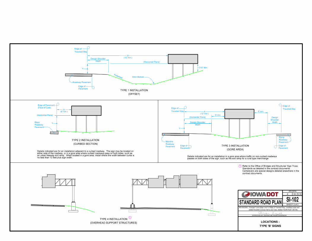
no less than 12 feet plus sign width.an urban freeway exit ramp. When located in a gore area, install where the width between curbs is either side of the roadway, or in a gore area where curbed roadways pass on both sides, such asDetails indicated are for an installation adjacent to a curbed roadway. The sign may be located on
passes on both sides of the sign, such as the exit ramp for a rural type interchange.Details indicated are for an installation in a gore area where traffic on non-curbed roadways
(CURBED SECTION)
TYPE 2 INSTALLATION
(GORE AREA)
TYPE 3 INSTALLATION
(OVERHEAD SUPPORT STRUCTURES)
TYPE 4 INSTALLATION
(12' min.)X
(12' min.)X
contract documents.
Cantalevers are special designs detailed elsewhere in the
Standards as detailed in the contract documents.
Refer to the Office of Bridges and Structures' Sign Truss

Section A-A
Top View
14''
A
A
A
A
4''
Ground Line
FRONT VIEW
Drill Holes
'' Field21
1
4'' nominal
6'' nominal
5' Embedment
190-50
190-51
SI-111
REVISION
04-19-16
SHEET 1 of 1
REVISIONS:
embedment. Added possible tabulations and replaced DOT logo in title block.
Added "nominal" to wood post dimensions. Labeled 5' depth of post
APPROVED BY DESIGN METHODS ENGINEER
STANDARD ROAD PLAN
2
WOOD POSTS
SUPPORT STRUCTURES -
Possible Tabulations:
Wood Posts for Type A or Type B Signs, 4 in. x 6 in.
Possible Contract Item:
190-51
190-50
SIGN PANEL
SI-112
REVISION
REVISIONS:
APPROVED BY DESIGN METHODS ENGINEER
STANDARD ROAD PLAN
New
1
2
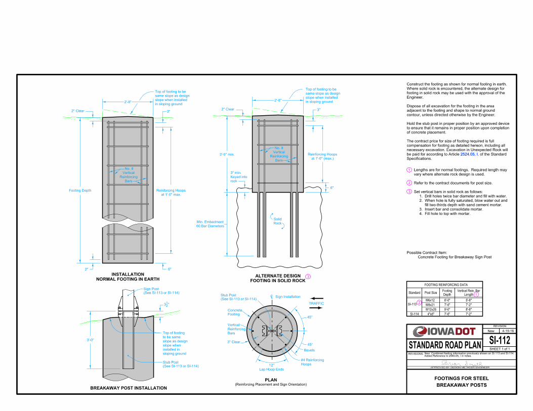
3
BREAKAWAY POSTS
FOOTINGS FOR STEEL
SHEET 1 of 1
4-19-16
Concrete Footing for Breakaway Sign Post
Possible Contract Item:
in sloping ground
slope when installed
same slope as design
Top of footing to be
in sloping ground
slope when installed
same slope as design
Top of footing to be
FOOTING IN SOLID ROCK
ALTERNATE DESIGNNORMAL FOOTING IN EARTH
INSTALLATION
Rock
Solid
3''
60 Bar Diameters
Min. Embedment
3'-0'' min.
6''
6''
Footing Depth
at 1'-0'' (max.)
Reinforcing Hoops
2''
3''2'' Clear
rock
Keyed into
3'' min.
2'' Clear
at 1'-0'' max.
Reinforcing Hoops
BREAKAWAY POST INSTALLATION
''21
3
sloping ground
installed in
slope when
slope as design
to be same
Top of footing
3'-0''
Bevels
Hoops
#4 Reinforcing
CL Sign Installation
45°
45°
Lap Hoop Ends
12''
3'' Clear
(Reinforcing Placement and Sign Orientation)
PLAN
Footing
Concrete
Bars
Reinforcing
Vertical
TRAFFIC
3
2'-8"2'-8"
Bars
Reinforcing
Vertical
No. 8
Bars
Reinforcing
Vertical
No. 8
(See SI-113 or SI-114)
Sign Post
2524.05, I
(See SI-113 or SI-114)
Stub Post
(See SI-113 or SI-114)
Stub Post
2524.05, I,
Specifications.
of the Standard be paid for according to Article
necessary excavation. Excavation in Unexpected Rock will
compensation for footing as detailed hereon, including all
The contract price for size of footing required is full
of concrete placement.
to ensure that it remains in proper position upon completion
Hold the stub post in proper position by an approved device
contour, unless directed otherwise by the Engineer.
adjacent to the footing and shape to normal ground
Dispose of all excavation for the footing in the area
Engineer.
footing in solid rock may be used with the approval of the
Where solid rock is encountered, the alternate design for
Construct the footing as shown for normal footing in earth.
4. Fill hole to top with mortar.
3. Insert bar and consolidate mortar.
fill two-thirds depth with sand cement mortar.
2. When hole is fully saturated, blow water out and
1. Drill holes twice bar diameter and fill with water.
Set vertical bars in solid rock as follows:
Refer to the contract documents for post size.
vary where alternate rock design is used.
Lengths are for normal footings. Required length may
FOOTING REINFORCING DATA
1Post Size
7'-6'' 7'-2"
2
Depth
Footing
Length
Vertical Rein. BarStandard
SI-114 4"x6"
W8x21 7'-6" 7'-2"
W12x26 9'-0'' 8'-8"
Added Reference to 2540.05, I in notes.New. Combined footing information previously shown on SI-113 and SI-114.
SI-113
W6x12 6'-0" 5'-8"
Side View
SIGN INSTALLATION
Post
Stub
Length
Post
Stub
30°
Sign Post
Post Length
Sign Face
4''
1''
''21
3
on sheet 2)
to details
BASE (Refer
BREAKAWAY
TRAFFIC
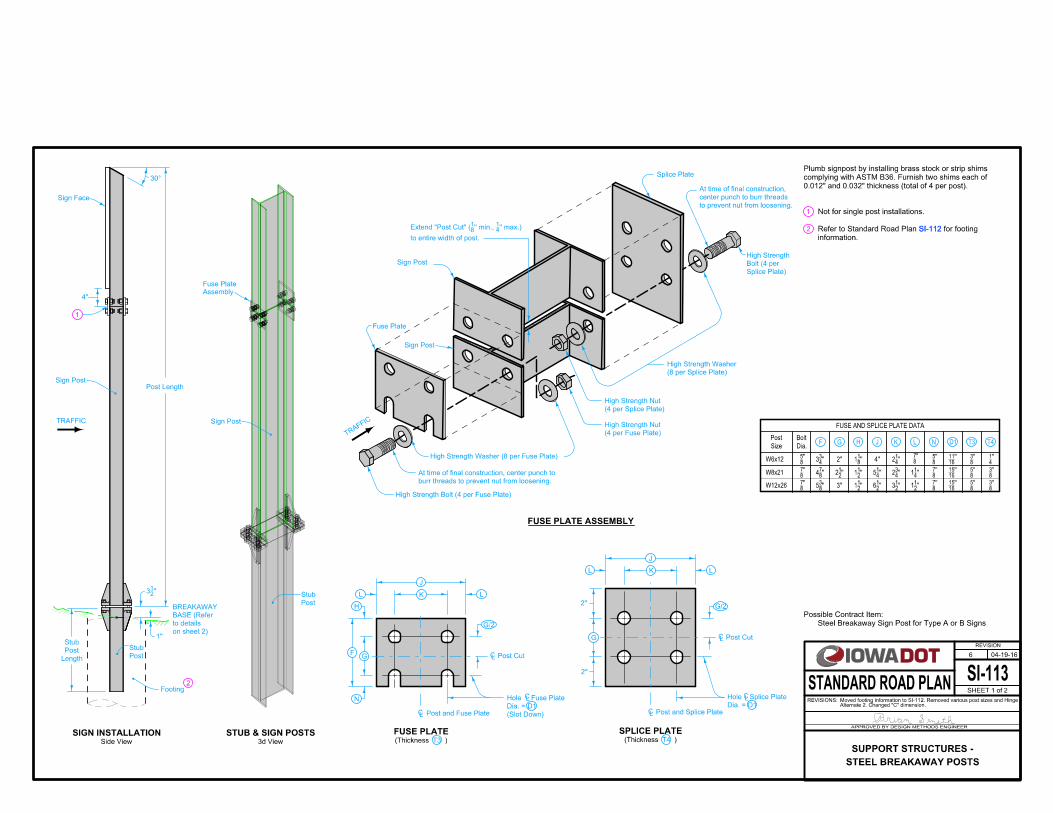
Steel Breakaway Sign Post for Type A or B Signs
Possible Contract Item:
(4 per Fuse Plate)
High Strength Nut
(4 per Splice Plate)
High Strength Nut
(8 per Splice Plate)
High Strength Washer
burr threads to prevent nut from loosening.
At time of final construction, center punch to
to prevent nut from loosening.
center punch to burr threads
At time of final construction,
3''
W8x21
W12x26
Size
Post
Dia.
Bolt
FUSE AND SPLICE PLATE DATA
FUSE PLATE ASSEMBLY
T4 )(Thickness
SPLICE PLATE
''83
5
''87
''87
''21
2
''21
1
''21
1
''21
6
''41
5
''21
3
''43
2
''21
1
''41
1
''87
''87
''1615
''1615
''83
''83
''85
''85
CL
CL
CL
CL
CLCL
J
F
TRAFFIC
Splice Plate
High Strength Washer (8 per Fuse Plate)
High Strength Bolt (4 per Fuse Plate)
Sign Post
LK
J
L
Dia. = D1
Hole Splice Plate
G
G/2
Post Cut
L
G
H
L
G/2
N
K
2''
Post and Fuse Plate Post and Splice Plate
2''
Post Cut
T4T3L N D1H J KGF
T3 )(Thickness
FUSE PLATE
(Slot Down)
Dia. = D1
Hole Fuse Plate
Splice Plate)
Bolt (4 per
High Strength
to entire width of post.
'' max.)41
'' min., 81
Extend "Post Cut" (
Fuse Plate
SI-112
Post
Stub
Sign Post
Assembly
Fuse Plate
Footing
1
0.012" and 0.032" thickness (total of 4 per post).
complying with ASTM B36. Furnish two shims each of
Plumb signpost by installing brass stock or strip shims
1
3d View
STUB & SIGN POSTS
2
2
SI-112
information.
for footing Refer to Standard Road Plan
Not for single post installations.
SI-113
REVISION
04-19-16
SHEET 1 of 2
REVISIONS:Alternate 2. Changed "C" dimension.Moved footing information to SI-112. Removed various post sizes and Hinge
APPROVED BY DESIGN METHODS ENGINEER
STANDARD ROAD PLAN
6
STEEL BREAKAWAY POSTS
SUPPORT STRUCTURES -
W6x12
''87
4
''43
3 2'' ''81
1 4'' ''41
2''
87 ''
85 ''
1611 ''
83 ''
41''
85
Sign Post
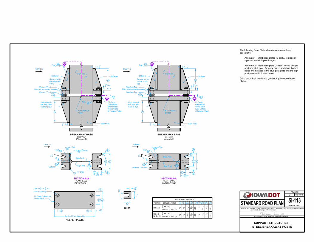
Plates.
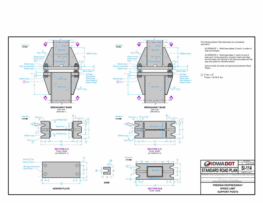
Grind smooth all welds and galvanizing between Base
post plate as indicated herein.
holes and notches in the stub post plate and the sign
post and stub post. Properly match and align the bolt
Alternate 2 - Weld base plate (1 each) to end of sign
signpost and stub post flanges.
Alternate 1 - Weld base plates (2 each), to sides of
equivalent:
The following Base Plate alternates are considered
SHIM
BREAKAWAY BASE DATA
Post Size Bolt Size & Torque EC DBA RT1 T2 W
''1613
''3215
''43
1
''43
1
(typ.)
center punch
Secure nut by
washer (typ.)
nut, bolt, and
High strength
POINT
REFERENCEA
Stiffener
A
T1
T1
Stub Post
Stiffener
Sign Post
''21
''21
'' typ.21
W
of Keeper Plate)
(See Details
Sheet Steel
Galvanized
28 Gage
A
A
Typ.
(typ.)
center punch
Secure nut by
washer (typ.)
nut, bolt, and
High strength
POINT
REFERENCEA
Typ.W
Stiffener
A
T1
T1
Stiffener
Sign Post
''21
''21
'' typ.21
W
of Keeper Plate)
(See Details
Sheet Steel
Galvanized
28 Gage
A
A
Typ.
SECTION A-APLAN - BASE
12
Stiffener
Flange
B
C
A
Sign Post
Stub Post
Typ.
D
E
E
A/2
W
T2
163
3
Typ.
Typ.
Stub Post
W
Stiffener Typ.
EW
D A
R
E
A/2
B
W
C
Sign Post
TRAFFIC
R
KEEPER PLATE
Sheet Steel
28 Gage Galvanized
Depth of Post Assembly
C C E
A
E
D
bolts (4 holes)
'' dia. 43
'' or 85
Drill for
(Alternate 1)
Side View
BREAKAWAY BASE
(Alternate 2)
Side View
BREAKAWAY BASE
(ALTERNATE 1)
SECTION A-A
(ALTERNATE 2)
PLAN - BASE
W
163
3
T2
TRAFFIC TRAFFIC
TRAFFIC
12
WTyp.
Flange
Shim as necessary
Washer (Typ.)
Washer (Typ.) Washer (Typ.)
Shim as necessary
Washer (Typ.)
Stub Post
SI-113
REVISION
04-19-16
SHEET 2 of 2
REVISIONS:Alternate 2. Changed "C" dimension. Moved footing information to SI-112. Removed various post sizes and Hinge
APPROVED BY DESIGN METHODS ENGINEER
STANDARD ROAD PLAN
6
STEEL BREAKAWAY POSTS
SUPPORT STRUCTURES -
W 12 x 26
W 8 x 21
Torque = 62.50 ft. lbs.
''21
'' dia. x 343
6" ''41
2 ''87 ''
21
3 ''41
1 1''''
43 ''
165 ''
3213
W 6 x 12Torque = 37.50 ft. lbs.
''43
'' dia. x 285
5" 2'' ''41
1 ''43
2 ''81
1 ''43 ''
21 ''
41 ''
3211

Sign Post
FRONT ELEVATION SIDE ELEVATION
Welded To Post
'' Plate Seal81
Stub Post
W8 x 21
'' Drain Notch43
A A
Slot (typ.)CL
Slot (typ.)CL
Slot (typ.)CL
Thickness
" Wall41
Sign Post
Rectangular
4" x 6"
6''4''
96''
51''
66''
27''
''21
2
10°
3''
''21
3
4''
2''
36''
'' x 1" Slotted Hole167
'' Drain Hole43
LengthPost
Sign Post
around corners
Weld continuously
" Weld 3 Sides163
Seal Weld, grind flush
Slot (typ.)CL
" (typ.)41
" x 21
" x 221
L 3
SECTION A-A
sheet 2)
to details on
BASE (Refer
BREAKAWAY
Stub Post
W8 x 21
Steel Breakaway Sign Post, Rectanguler Tube
Possible Contract Item:
SI-1121 SI-112
information.
for footing Refer to Standard Road Plan
0.012" and 0.032" thickness (total of 4 per post).
complying with ASTM B 36. Furnish two shims each of
Plumb signpost by installing brass stock or strip shims
SI-112
Footing1
OBLIQUE FRONT VIEW OBLIQUE BACK VIEW
SI-114
REVISION
04-19-16
SHEET 1 of 2
REVISIONS:Moved footing information to SI-112. Changed title and added oblique views.
APPROVED BY DESIGN METHODS ENGINEER
STANDARD ROAD PLAN
3
SUPPORT POSTS
SPEED LIMIT
FREEWAY/EXPRESSWAY
2
SHIM
SECTION B-BPLAN - BASE
TRAFFIC
TRAFFIC
''3215
''43
1''1613
''43
1
TRAFFIC
KEEPER PLATE
Sheet Steel
28 Gage Galvanized
bolts (4 holes)
'' dia. 43
Drill for
''43
12
''87
''87 ''4
11
''21
3 6''
''41
1
12163
3
R = 1332''
Sign Post
Stiffener (typ.)
''87
''43
12
''87
''43
''83
3 6'' ''83
3
6''
''41
1
''21
3
''41
1
(typ.)
center punch
Secure nut by
TRAFFIC
Sign Post
B
C C
B
(typ.)2
Stiffener (typ.)
Base Plates
Stub Post
'' Drain Notch43
Washer (typ.)
Washer (typ.)
Shim as necessary
Washer (typ.)
'' 41
Typ.
Typ.''
165
1''
6''
'' typ.21
'' typ.21
"41
Typ.
6''
1''
(typ.)
center punch
Secure nut by
TRAFFIC
Sign Post
B
C C
B
(typ.)2
Stiffener (typ.)
Base Plates
Stub Post
'' Drain Notch43
Washer (typ.)
Washer (typ.)
Shim as necessary
Washer (typ.)
'' 41
Typ.
Typ.''
165
1''
6''
'' typ.21
'' typ.21
"41
Typ.
6''
1''
12
Typ.
Stub Post
Typ.
163
3''
3213
R =
Flange (typ.)
Stiffener (typ.)
"165
"165
"165
6''
''41
1''41
2''41
8
''43
12
''41
2
''43
3''
''21
3
Typ."
165
''85
2
Typ."
165
''43
Stiffener (typ.)
"165
Typ.
163
3
12
''41
2 ''41
8 ''41
2
''43
12
''41
1
''3213
R =
''21
3 6''
''41
1
''83
1
''87
''83
1
''87
''41
1
Stub Post''85
2
3''
Keeper Plate)
(See Details of
Sheet Steel
Galvanized
28 Gage
Keeper Plate)
(See Details of
Sheet Steel
Galvanized
28 Gage
"165
Typ.
(Alternate 1)
Side View
BREAKAWAY BASE
(Alternate 2)
Side View
BREAKAWAY BASE
SECTION C-C
(ALTERNATE 2)
PLAN - BASE
SECTION C-C
(ALTERNATE 1)
PLAN - BASE
"165
Flange (typ.)
Torque = 62.50 ft. lbs.
" 21
" dia. x 343
Plates.
Grind smooth all welds and galvanizing between Base
sign post plate as indicated hereon.
the bolt holes and notches in the stub post plate and the
stub post. During assembly, properly match and align
ALTERNATE 2 - Weld base plate (1 each) to end of
stub post flanges.
ALTERNATE 1 - Weld base plates (2 each) to sides of
equivalent:
The following Base Plate alternates are considered
SI-114
REVISION
04-19-16
SHEET 2 of 2
REVISIONS:Moved footing information to SI-112. Changed title and added oblique views.
APPROVED BY DESIGN METHODS ENGINEER
STANDARD ROAD PLAN
3
SUPPORT POSTS
SPEED LIMIT
FREEWAY/EXPRESSWAY

SIGN MOUNTING BARAUXILIARY
Type 1
PIPE DETAIL
Type 4A
Type 3
Type 2
(Bracket 'F')
PIPE DETAIL
Type 4B
(Bracket ''F '')1
2''
56"
18''
" on 6" centers167
All holes
" x 2" flat steel, galvanized41
" bolts83
for
" Dia hole167
L as required L
Type 5
18"
68"
20"
27"
30"
33"
"167
All holes
" x 2" flat steel, galvanized41
FOR 24" ROUTE SHIELDSSIGN MOUNTING BRACKET
TWO POST
24"
98"
26"
39"
"21
43
48"
"167
All holes
" x 2" flat steel, galvanized41
18"
35"
20"
"167
All holes
" x 2" flat steel, galvanized41
"21
13
"21
16
2''
75"
18''" bolts8
3for
" Dia hole167
24"
50"
26"
"21
19
24"
"167
All holes
" x 2" flat steel, galvanized41
FOR 36" ROUTE SHIELDSSIGN MOUNTING BRACKET
ONE POST
FOR 24" ROUTE SHIELDSSIGN MOUNTING BRACKET
ONE POST
Type 6
FOR 36" ROUTE SHIELDSSIGN MOUNTING BRACKET
TWO POST
bolts, washers, nuts, and set screws.Bid price for the brackets is to include the necessary mounting
SI-119
REVISION
10-17-17
SHEET 1 of 2
REVISIONS:OF SIGN on page 2.Auxiliary sign mounting brackets have been added to 3D VIEW BACK
APPROVED BY DESIGN METHODS ENGINEER
STANDARD ROAD PLAN
3
MOUNTING BRACKETS
SUPPORT STRUCTURES -
Existing Stop Sign Mounting Bolt
Washer
R5-1 Sign
Washer
1
SECTION A-A
FOR SINGLE WOOD POST INSTALLATIONTYPICAL MOUNTING BRACKET ARRANGEMENT
NutSelf-Locking
Pipe Bracket 'F'
2
BACK OF SIGN
BACK OF SIGN3D VIEW
2'' Post Clamps
Required Per Sign)(2 Sign Mounting BarsBracket Assembly 'H'
Mounting BracketType 2/Type 5 Sign
2mounting barAuxiliary sign 2
mounting barAuxiliary sign
1
1
Mounting BracketType 3/Type 6 Sign
FOR TWO WOOD POST INSTALLATIONTYPICAL MOUNTING BRACKET ARRANGEMENT
3
33 3
(See BACK OF SIGN)Sign Mounting Bar for R5-1
" Dia hex head bolt, Length 7"83
2'' Dia. Galvanized Steel Pipe
Existing Stop Sign
4
44
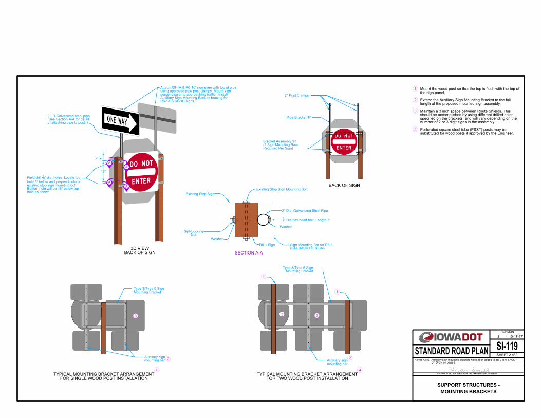
substituted for wood posts if approved by the Engineer.Perforated square steel tube (PSST) posts may be
number of 2 or 3 digit signs in the assembly.specified on the brackets, and will vary depending on theshould be accomplished by using different drilled holes Maintain a 3 inch space between Route Shields. This
length of the proposed mounted sign assembly.Extend the Auxiliary Sign Mounting Bracket to the full
the sign panel.Mount the wood post so that the top is flush with the top of
of attaching pipe to post. )(See Section A-A for detail2" ID Galvanized steel pipe
hole as shown.Bottom hole will be 18" below topexisting stop sign mounting bolt.hole 3" below and perpendicular to
" dia. holes. Locate top167
Field drill
3"
18"
A
A
A
A
R6-1A & R6-1C signs.Auxiliary Sign Mounting Bars as bracing forperpendicular to approaching traffic. Installusing approved pipe post clamps. Mount signAttach R6-1A & R6-1C sign even with top of pipe
SI-119
REVISION
10-17-17
SHEET 2 of 2
REVISIONS:OF SIGN on page 2.Auxiliary sign mounting brackets have been added to 3D VIEW BACK
APPROVED BY DESIGN METHODS ENGINEER
STANDARD ROAD PLAN
3
MOUNTING BRACKETS
SUPPORT STRUCTURES -
INTERSTATE
20
INTERSTATE
420 B
DE
F
C
G
C
KL
J
J
M M
J
DE
F
B
CG
C
KL
M
J
J
J
H H
**
*
H H
*
**
Width Height
48
36
24
13
10
6
60
45
30
16.25
7.5
48
36
24
13
10
6
48
36
24
13
10
6
4.6125
3.075
1.92
6.57
4.38
2.74
5
4
2.5
1.5
1
0.625
5
4
2.5
1.5
1
0.625
4
2.75
2
0.875
0.75
0.5
4
2.75
2
0.875
0.75
0.5
30
22.5
15
8.125
6.25
3.75
34
25.5
17
9.2083
7.0833
4.25
30
22.5
15
8.125
6.25
3.75
48
36
24
13
10
6
10
7.5
5
1.25
10
7.5
5
1.25
9.5
6.375
3.375
2.5
1.5
9.5
6.375
3.375
2.5
1.5
20
15
10
5.5
4.25
2.5
20
15
10
5.5
4.25
2.5
11.5
7.625
4.125
3.25
2
11.5
7.625
4.125
3.25
2
1
0.75
0.5
0.125
1
0.75
0.5
0.125
Sign
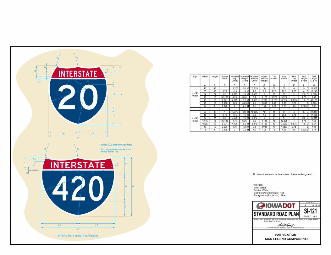
INTERSTATE ROUTE MARKERS
vertical center line.
** Optically space numerals about
* Series 2000 Standard Alphabets.
All dimensions are in inches unless otherwise designated.
Background (Route No.): Blue
Background (Interstate): Red
Border: White
Text: White
COLORS:
Thick.Border
& FontHeight
Numeral
HeightSectionUpper
RadiusTop
RadiusSide
OffsetTopText
& FontHeightText
Lt & RtLengthText
A B C D E F G H J K L M
OffsetTop
Numeral
OffsetBottom
Numeral
C
C
C
C
C
C
E
E
E
E
E
E
C
C
C
C
C
C
B
B
B
B
B
B
0.271
0.208
0.271
0.208
2.708
2.083
2.708
2.083
Routes
3 Digit
A21
A21
A
A
A21
A21
15.375
15.375
12
12.625
12.625
Routes
2 Digit
15.307
12.246
7.658
21.818
17.455
10.911
C
EB
15
18.75
15
15
0.3125 4.75 6.35 3.9 3.125 9.375 9.375 1 1.75
C
5.32
0.3125 4.75 6.35 3.9 3.125 15 10.625 1 1.75 7.58
SI-121
REVISION
10-16-18
SHEET 1 of 5
REVISIONS:Circle Note 2 to Sheet 4.Added 15" tall route shields for Interstates, U.S. Hwys, & IA Hwys. Added
APPROVED BY DESIGN METHODS ENGINEER
STANDARD ROAD PLAN
4
SIGN LEGEND COMPONENTS
FABRICATION -
40
420
1
1
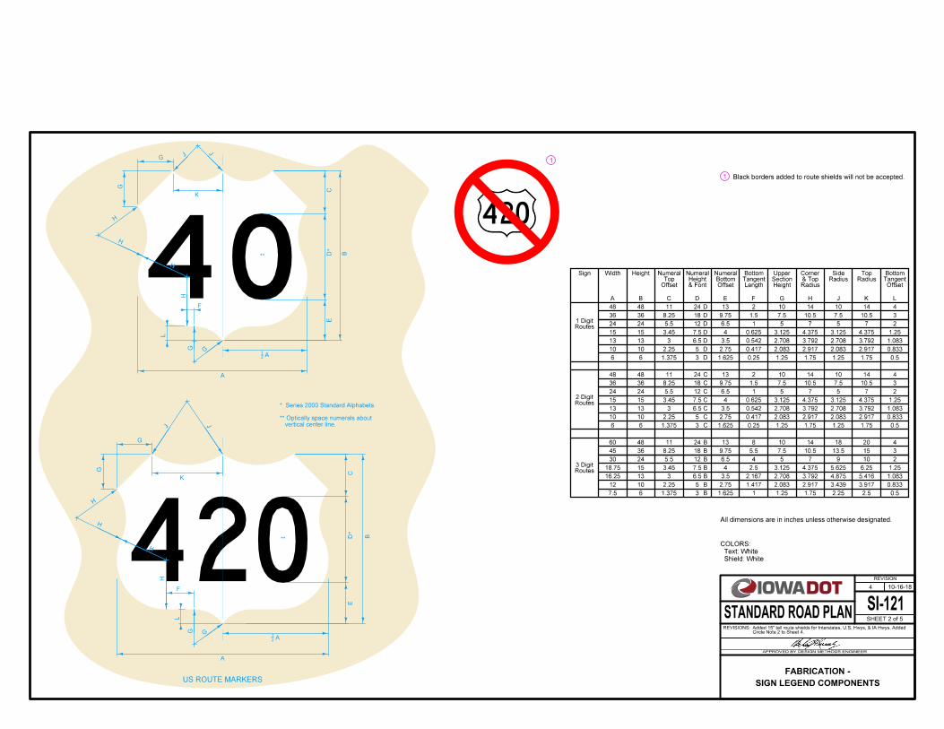
US ROUTE MARKERS
B
CD
E
L
F
A
CD
E
B
G
G
K
A
G
G
K
L
F
J
J
H
H
H
H
G G
J J
H
H
H
H
G G
***
* Series 2000 Standard Alphabets.
***
48 48 11 24 13 2
36 36 8.25 18 9.75 1.5
24 24 5.5 12 6.5 1
13 13 3 6.5 3.5 0.542
10 10 2.25 5 2.75 0.417
6 6 1.375 3 1.625 0.25
60 48 11 24 13 8
45 36 8.25 18 9.75 5.5
30 24 5.5 12 6.5 4
16.25 13 3 6.5 3.5 2.167
10 2.25 5 2.75
7.5 6 1.375 3 1.625 1
10 14 10 14 4
7.5 10.5 7.5 10.5 3
5 7 5 7 2
2.708 3.792 2.708 3.792 1.083
2.083 2.917 2.083 2.917 0.833
1.25 1.75 1.25 1.75 0.5
10 14 18 20 4
7.5 10.5 13.5 15 3
5 7 9 10 2
2.708 3.792 4.875 5.416 1.083
2.083 2.917 0.833
1.25 1.75 2.25 2.5 0.5
Sign Width Height
** Optically space numerals about
vertical center line.
Shield: White
Text: White
COLORS:
& FontHeight
Numeral
LengthTangentBottom
A B C D E F G H J K L
OffsetTop
Numeral
OffsetBottom
Numeral
HeightSectionUpper
Radius& TopCorner
RadiusSide
RadiusTop
OffsetTangentBottom
All dimensions are in inches unless otherwise designated.
C
C
C
C
C
C
B
B
B
B
B
BRoutes3 Digit
A21
A21
48 48 11 24 13 2
36 36 8.25 18 9.75 1.5
24 24 5.5 12 6.5 1
13 13 3 6.5 3.5 0.542
10 10 2.25 5 2.75 0.417
6 6 1.375 3 1.625 0.25
10 14 10 14 4
7.5 10.5 7.5 10.5 3
5 7 5 7 2
2.708 3.792 2.708 3.792 1.083
2.083 2.917 2.083 2.917 0.833
1.25 1.75 1.25 1.75 0.5
D
D
D
D
D
D
12
Routes2 Digit
Routes1 Digit
1.417 3.439 3.917
Black borders added to route shields will not be accepted.
D
C
B
15 15
15 15
1518.75
3.45 7.5
3.45
3.45
7.5
7.5
4
4
4
0.625
0.625
2.5
3.125
3.125
3.125
4.375
4.375
4.375
3.125
4.375
4.375
6.25
3.125
5.625
1.25
1.25
1.25
SI-121
REVISION
10-16-18
SHEET 2 of 5
REVISIONS:Circle Note 2 to Sheet 4.Added 15" tall route shields for Interstates, U.S. Hwys, & IA Hwys. Added
APPROVED BY DESIGN METHODS ENGINEER
STANDARD ROAD PLAN
4
SIGN LEGEND COMPONENTS
FABRICATION -

420
1
1
Sign Width Height
B
A
CD
C
R
B
**
*
A
CD
C
R
**
*
Shield: White
Text: Black
COLORS:
vertical center line.** Optically space numerals about
* Series 2000 Standard Alphabets.
STATE ROUTE MARKERS
48 48 12 24 24 -
36 36 9 18 18 -
24 24 6 12 12 -
13 13 3.25 6.5 6.5 -
10 10 2.5 5 5 -
6 6 1.5 3 3 -
60 48 12 24 24 12
45 36 9 18 18 9
30 24 6 12 12 6
16.25 13 3.25 6.5 6.5 3.25
10 2.5 5 5
7.5 6 1.5 3 3 1.5
& FontHeight
Numeral
A B C D R T
OffsetNumeral Radius Tangent
C
C
C
C
C
C
B
B
B
B
B
BRoutes3 Digit
T
A21
48 48 12 24 24 -
36 36 9 18 18 -
24 24 6 12 12 -
13 13 3.25 6.5 6.5 -
10 10 2.5 5 5 -
6 6 1.5 3 3 -
D
D
D
D
D
D
Routes1 Digit
Routes2 Digit
12 2
All dimensions are in inches unless otherwise designated.
Black borders added to route shields will not be accepted.
-D
-C
B
15 15
15 15
1518.75
3.75
3.75
3.75
7.5
7.5
7.5
7.5
7.5
7.5 3.75
SI-121
REVISION
10-16-18
SHEET 3 of 5
REVISIONS:Circle Note 2 to Sheet 4.Added 15" tall route shields for Interstates, U.S. Hwys, & IA Hwys. Added
APPROVED BY DESIGN METHODS ENGINEER
STANDARD ROAD PLAN
4
SIGN LEGEND COMPONENTS
FABRICATION -

2
2
T
A
B
T
D E
FG
F E
H
*
*
*
Background: White
Shield: Blue
Border: Yellow
Text: Yellow
COLORS:
HeightSign
* Series 2000 Standard Alphabets.
** Optically space numerals about
vertical center line.
COUNTY ROUTE MARKER
A B C D E F G H J K L M
RadiusSide
N P Q R S T
WidthBottom
OffsetTop
County
& FontText HgtCounty
OffsetNumeral
& FontHeight
Numberal
OffsetBottomCounty
OffsetVerticalRadius
OffsetVerticalCorner
OffsetLateralCorner
OffsetLateralRadius
Lt & RtNameCounty
RightText
County
LeftText
CountyRadius
TopPlaque
Backgrnd
RoutesAll 14 VAR6.75 4.75 7.5 10 427.75 40.536 21.25 3 4 103 12
All dimensions are in inches unless otherwise designated.
R
K
J
ML
N
P Q
POTTAWATTAMIE
COUNTY
G8L**
C C
S
N
C
C
& IndentThick.Border
7
***
and vertically on white background plaque
** County shield centered horizontally
POTTAWATTAMIE
COUNTY
G8L
Yellow sheeted background plaque will not be accepted.
SI-121
REVISION
10-16-18
SHEET 4 of 5
REVISIONS:Circle Note 2 to Sheet 4.Added 15" tall route shields for Interstates, U.S. Hwys, & IA Hwys. Added
APPROVED BY DESIGN METHODS ENGINEER
STANDARD ROAD PLAN
4
SIGN LEGEND COMPONENTS
FABRICATION -

constraints.applications except where not practical due to size Type II-A arrows should be used in all typical"down arrow" 2
I-E, 45
A
R
B
L
R
C
S
D
E
R
A
L
D
S
CR
B
RARROW DESIGNATION:
G
6.75
18.25 14
3.75 4.36
17.5
19.75
9.75
14
22.25 17 1
1.75 5.78
I-A
I-B
I-C
I-D
I-E
I-F
ID Length
L A B C R D E S
SizeLetter
LengthShaft
at TailWidthShaft
at HeadWidthShaftTipRadiusDraft
LengthHead
WidthHead
Round
Round
Round
Round
Round
Round
17
25
20
25
30
35
22.25
18.25
15.125
15.125 11.5625
11.5625
17
1.3125
1.3125
1.5
1.5
1.75
1
0.75
0.75
0.8125
0.8125 3.75
4.5
4.5
5.375
5.375
4.03
4.81
5.23
6.2
7.5
14.75
8
8
10-13.3
10-13.3
16
16
G
6.5
II-B
II-A
ID Length
L A B C R D E
at TailWidthShaft
at HeadWidthShaftTipRadiusDraft
LengthHead
WidthHead
Point
Point
16
22
6.2524
32
12
16
2.25
3
0.75
1
4.875
9
TYPE II
Part 1 is the arrow ID number
the horizontal
°0'0"45
All dimensions are in inches unless otherwise designated.
TYPE III
G
ID Length
L A B C R D
at HeadWidthShaftTipRadiusDraft
LengthHead
WidthHead
Round
Round
Round
Round
Round
Round
Round
Round
III-4S
III-4L
III-5S
III-5L
III-6S
III-6L
III-8S
III-8L
6
12
8
12
8
14
10.5
14
4
4
5
5
6
6
8
8
3.3125
3.3125
4.140625
4.140625
4.96875
4.96875
6.625
6.625
0.375
0.375
0.46875
0.46875
0.5625
0.5625
0.75
0.75
0.25
0.25
0.3125
0.3125
0.375
0.375
0.5
0.5
1.5
1.5
1.875
1.875
2.25
2.25
3.0
3.0
3.0625
9.0625
4.328
8.328
3.59375
9.59375
4.625
8.125
LengthShaft
Each arrow used on a guide sign is identified by a two part code as follows:
S
L
B
R
D
S
C
R
R
A
Part 2 is the angle in degrees between the center line of the arrow and
TYPE I
SI-121
REVISION
10-16-18
SHEET 5 of 5
REVISIONS:Circle Note 2 to Sheet 4.Added 15" tall route shields for Interstates, U.S. Hwys, & IA Hwys. Added
APPROVED BY DESIGN METHODS ENGINEER
STANDARD ROAD PLAN
4
SIGN LEGEND COMPONENTS
FABRICATION -

CL
CL
1
0.410''
0.222''
0.084''
0.078''0.125'' R
0.125'' R
6.000''
0.078''0.125'' R
0.078''
Actual Length of Panels = Design Length + 1.5"
ASSEMBLY DETAIL
STANDARD STRUCTURAL SIGN PANELS
EDGE MOLDING
R
Metal Edge Molding
EDGE MOLDING BORDER STRIP DETAIL
12''
12''
12''
12''
Panel Bo
lts
1
0.250'' R
0.125'' R
0.250'' R
Full Panel Section
Half Panel Section
2.000''
0.078''
0.750'' 0.500''R.
0.050''
0.188''
0.078''
0.500''
2.000'' 0.250''
0.084''
0.156''
0.084'' 0.222''
0.687''
2.000''
0.410''
0.216''
0.687''
0.125''0.250''
0.078''
0.081''
0.125''
12.000''
0.078''
6.000''
or border strip permitted.
No overlap of edge molding
Border Strip
Full Width of
of each sign. Attach in accordance with current specifications.
Edge molding shall be installed full length of each vertical side
(for Pan
el Bolts)
'' Slotted
Holes
87
'' x 167
''1613
90
''1613
'' Slot, both sides87
'' x167
"1613
''43
data for individual sign fabrication requirements.Refer to detail project plans and summary sheet for exact
of the sign.required, in which case it shall be placed at the top edge Signs shall be made up of full panels unless a half panel is
from the ends of the panel.outermost slots are of equal distances (not to exceed 6 inches) located along the full length of each panel, such that the Panel bolt slotted holes spaced at 12 inch centers shall be
0.78"
SI-123
REVISION
04-19-16
SHEET 1 of 1
REVISIONS:Replaced the logo in the title block with the new version and modified two
dimensions on the Full Structure Section drawing.
APPROVED BY DESIGN METHODS ENGINEER
STANDARD ROAD PLAN
2
TYPE 'B' SIGNS
FABRICATION -
(one side only)
'' Slot,87
'' x167Section
Half Panel
Section
Full Panel
Two washers per panel bolt, one each side of sign.

Wood Sign Post
Steel Breakaway Sign Post
Possible Contract Items:
CL
Post
CL
48"
36"
PostSign
66"
96"
51"
27"(Typ.)L Slot C
Post
Sign
Sign Face
Sign Face
Flag Bracket
30"
36"
8"
3"
" 41
"1611
2
"1611
2
FaceSign
Sign Post
Bolt
" Length21
1
" Diameter83
SECTION B-BSECTION D-D
SECTION C-C
Zee BarAluminum
Lock NutNylon
"41
1
ALUMINUM ZEE BAR
Nylon Lock Nut
1" OD Washer
Zee BarAluminum
for flag bracketsholes in Z barNote: Field Drill
1" OD Washer
FOR FLAGS
ATTACHMENT DETAILS
BACK ELEVATION
POST ATTACHMENT DETAILS
4" x 6" RECTANGULAR TUBE
BACK ELEVATION
3"
SECTION A-A
A
A
B
B
C
C
D
D
CL
Washer
PLAN
Self-Locking Nut
Washer
" Thick 81
" OD x 21
1Sign Face
DepthNominal
WidthNominal
Length - Nominal Depth + 1"
'' dia. Hex Head Bolt83
L Bracket
Sign Post
Aluminum Z Bar
"41
" Bolt21
" x 183
1" OD Washer
1" OD Washer
Washer
" Thick 81
" OD x 21
1
CL CL
" x 1" Slot (Typ.)16 7
"41
1
Zee BarAluminum
" Bolt21
" x 183
Nylon Lock Nut
Aluminum Zee Bar
" 41
POST ATTACHMENT
RECTANGULAR TUBE
TUBE POST ATTACHMENT
WOOD OR PERFORATED SQUARE
Post*
*NOTE: Treated Wood or Perforated Square Tube Post
SI-114SI-114
rectangular tube.
for details of steel breakaway sign post Refer to
SI-131
REVISION
10-18-16
SHEET 1 of 1
REVISIONS:Replaced old Iowa DOT logo with new logo.
APPROVED BY DESIGN METHODS ENGINEER
STANDARD ROAD PLAN
4
TYPE 'A' SIGNS
INSTALLATION -

CLIP INSTALLATION
1''
0.360''
Nut
Post Clip Bolt flange after nuts are tightened.
shall fit tightly against the post
Sign Face
4'' x 6'' (Nominal) Sign Post
4'' x 6'' (Nominal) Sign Post
Rib
Post
Clip
Post Clip
Clips
Clips
Rib
Post
Post
Panel
12"
Panel
6"
Panel + 2''
Length = Sign
Delineator Post
PLAN
Panel
12"
Panel
12"
Clip
Washer
The shank of the post clip bolt
POST CLIP
Sign Face
Post Flange
ELEVATION
Delineator post
Delineator Post
1'' min.
ELEVATION
Delineator Post
(Square or Rectangualr Head Optional)
CLIP BOLT
mounted on overhead sign support structures.
Type 4 Attachment shall be used for all signs
TYPE 4 ATTACHMENT
signs placed on metal breakaway posts.
Type 1 Attachment shall be used for all
TYPE 1 ATTACHMENT
)''6433(
0.641''
0.015''+'' 163
''83
''43
1
with a minimum of 3 bolts per post.
bottom of sign plus 1 bolt per sign panel
'' Post Bolts - place bolts near top and165
''32
191
''6431
1
''167
''6411
2
''83
1
all signs with wood posts.
Use Type 3 Attachment for
TYPE 3 ATTACHMENT
0.48''
4186.09, B4186.09, B of the Standard Specifications.Article
and washers for post clips meeting the requirements of
Use cast aluminum post clips and stainless steel nuts, bolts,
aluminum angles.
incidental item. No separate payment will be made for
hardware and are to be furnished by the Contractor as an
The aluminum angles are considered part of the mounting
extrusion joint.
A post clip is required on each angle at top of panel and each
sign.
shown, they can be moved so as to securely hold the top
If the angle fasteners can not be horizontally placed as
two signs line up, panel bolts are to be used.
If the bolt holes in the top panel and the bottom panel of the
exit.
aligned with the edge of the guide sign indicating direction of
Position the EXIT NUMBER PANEL above the guide sign
SI-132
REVISION
04-17-18
SHEET 1 of 2
REVISIONS:and the nut, bolt, and washer fastening the post clip.Added thickness dimension for post clip. Specified material for the post clip,
APPROVED BY DESIGN METHODS ENGINEER
STANDARD ROAD PLAN
4
TYPE 'B' SIGNS
INSTALLATION -

GUIDE SIGNS
0.2W 0.6W
W
0.2W
Breakaway steel posts
Existing sign support or
3'-0'' 3'-0''18'' 3'-0''
2H + 3''
18''
H
H
Maximum Spacing
3'-0''
2H + 3''
Top of existing support.
'' x (3H+3'')83
'' x 21
'' x 221
2
Aluminum L
'' 83
'' x 21
'' x 221
2
Aluminum L's
or to bottom of panel.
Length = 3H + 3''
1
1
1
2
2 Sign height added above existing supports.
of the major sign.
Do not allow the aluminum L to extend below the bottom
SI-132
REVISION
04-17-18
SHEET 2 of 2
REVISIONS:and the nut, bolt, and washer fastening the post clip.Added thickness dimension for post clip. Specified material for the post clip,
APPROVED BY DESIGN METHODS ENGINEER
STANDARD ROAD PLAN
4
TYPE 'B' SIGNS
INSTALLATION -

Self-Locking Nut
Post
WidthNominal
Self-Locking Nut
Post
Sign Face
FOR SHEET ALUMINUM SIGNS ONLY
NOTE: FOR SINGLE POST WITH SIGN WIDTH > 24" AND HEIGHT > 24"
L/2
L/2
L L
L/2
L/2
L
L/2
L/2
L
L/2
L/2
DepthNominal
Thick Washer
"81" OD x
21
1
Thick Washers (2)
"81" OD x
21
1
"21Length- Nominal Depth + 1
" dia. Hex Head Bolt x83
WidthNominal
Thick Washer
"81" OD x
21
1
Thick Washers (2)
"81" OD x
21
1
"21Length- Nominal Depth + 1
" dia. Hex Head Bolt x83
Sign Face
DepthNominal
Center of Sign Only
Shim Placed in Center of Sign Only
Shim Placed in FOR PSST POST
SHIM ATTACHMENT DETAIL
SI-133
REVISION
10-17-17
SHEET 1 of 1
REVISIONS:NEW
APPROVED BY DESIGN METHODS ENGINEER
STANDARD ROAD PLAN
NEW
INSTALLATION - TYPE "A" SIGN SHIM
FOR WOOD POST
SHIM ATTACHMENT DETAIL

TYPE 9
TYPE 4
TYPE 3
TYPE 2
TYPE 1 TYPE 5
TYPE 6
4 ft
4 ft
4 ft
4 ft4 ft
4 ft
TYPE 7
4 ft
4 ft
TYPE 8
REFERENCE LOCATION SIGN ASSEMBLY
Type 1
Reference Location Sign
8 ft Typical
8 ft Typical
2 ft Minimum
2 ft Minimum
Bracket
Mounting
Special
BracketMountingSpecial
BracketSpecial MountingHigher Rail with aInstall on the
Delineator
embedment when installed at the specified mounting height.
1
SHOULDER INSTALLATION
CURB INSTALLATION
DEPRESSED MEDIAN INSTALLATION
RAISED MEDIAN INSTALLATION
BRIDGE BARRIER RAIL INSTALLATION FULL MEDIAN BARRIER RAIL INSTALLATION
ATTACHMENT TO OTHER FEATURE SPLIT MEDIAN BARRIER RAIL INSTALLATION
TOP VIEW
WITH GRADE DIFFERENTIAL
SPLIT MEDIAN BARRIER RAIL INSTALLATION
truss legs, etc.
be light poles, sign
Other features could
in the median
Center post
in the median
Center post
in the median
Center post
1
1
1
1
1
" O.D. x 0.091".1611
" I.D. x 3211
hex selflocking nuts with washers
" - 18 NC hex bolts and 41
" x 2165
self-locking nuts, and washers. Hot dipped galvanized steel bolts,
Hot Dipped Galvanized Washer1 1/2" O.D. 1/8" thick
All dimensions are in inches unless otherwise designated.
" holes in delineators are acceptable.167
" or 83
in the plans.Furnish Type 1 delineator posts for each location unless specified otherwise
Install post of sufficient length to provide a minimum of 30 inches of
steel bands.
with stainless
Attach to feature
SI-171
REVISION
04-18-17
SHEET 1 of 4
REVISIONS:Changed title and "milepost" to new Reference Location Sign naming.
APPROVED BY DESIGN METHODS ENGINEER
STANDARD ROAD PLAN
3
REFERENCE LOCATION SIGN POSTS

34
1.29.6
310
2.9 6.2
310
1.22.9
3
36
12
D10-2A;
1.50" Radius, 0.50" Border, White on Green;
[MILE] C 2K;
[4] C 2K; [4] C 2K;
MILE
44
34
1.29.6
310
2.9 6.21.2
2.9
4
24
12
D10-1A;
1.50" Radius, 0.50" Border, White on Green;
[MILE] C 2K;
[4] C 2K;
MILE
4
34
1.29.6
310
2.9 6.2
2.5
10
2.5
10
1.22.9
3
48
12
D10-3A;
1.50" Radius, 0.50" Border, White on Green;
[MILE] C 2K;
[4] C 2K; [4] C 2K;
[4] C 2K;
MILE
4
44
28
1.928.16
1.92
2
12
12
D10-7A;
1.50" Radius, 0.50" Border, White on Green;
[A] E 2K;
A
28
0.6410.72
0.64
2
12
12
D10-8A;
1.50" Radius, 0.50" Border, White on Green;
[AH] C 2K;
AH
28
0.8410.32
0.84
2
12
12
D10-9A;
1.50" Radius, 0.50" Border, White on Green;
[BK] C 2K;
BK
0.2
511.5
0.2111.58
0.21
0.2
512
12
D10-5A;
1.50" Radius, No border, White on Black;
0.2
511.5
0.2511.5
0.25
0.2
512
12
1.50" Radius, No border, White on Black;
Rounded Rectangle 5.75" Radius;
48
SI-171
REVISION
04-18-17
SHEET 2 of 4
REVISIONS:Changed title and "milepost" to new Reference Location Sign naming.
APPROVED BY DESIGN METHODS ENGINEER
STANDARD ROAD PLAN
3
REFERENCE LOCATION SIGN POSTS
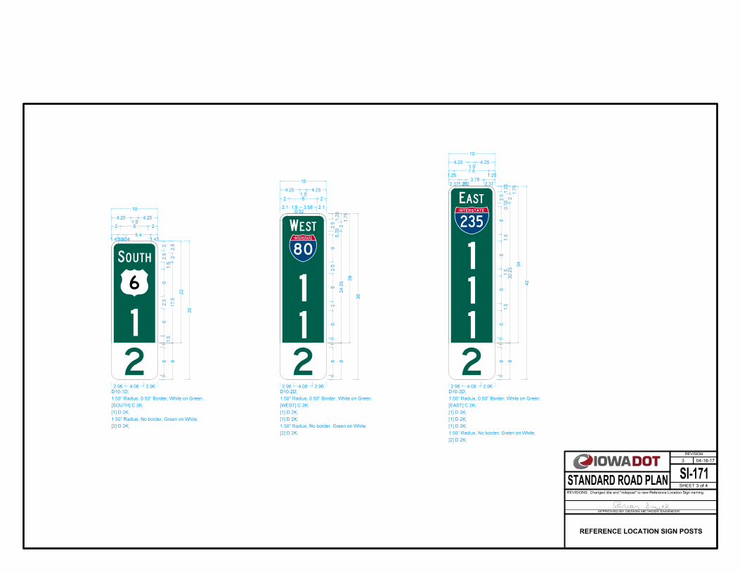
22.5
1.431.4
2.5
2
0.345.4
1.5
6
2 6
2.5
6
4.251.5
1.43
2
4.25
1.5
17.5
22
10
1.50" Radius, 0.50" Border, White on Green;
[SOUTH] C 2K;
[1] D 2K;
16
2.96 4.08 2.96
1
8
1.50" Radius, No border, Green on White;
[2] D 2K;
30
D10-1D;
1
2
SOUTH
1.2
52.5
2.1 1.9
1.7
52
0.323.58
0.7
56
2 6
2.5
6
4.251.5
26
2.1
2
4.25
1
24.2
5
28
10
1.50" Radius, 0.50" Border, White on Green;
[WEST] C 2K;
[1] D 2K;
[1] D 2K;
16
2.96 4.08 2.96
1
8
1.50" Radius, No border, Green on White;
[2] D 2K;
36
D10-2D;
WEST
1
21
1.2
52.5
2.371.28
1.7
52
0.23.78
0.7
56
1.257.5
1.5
6
4.251.5
1.5
61.5
6
2.37
1.25
4.25
1
30.2
5
34
10
1.50" Radius, 0.50" Border, White on Green;
[EAST] C 2K;
[1] D 2K;
[1] D 2K;
[1] D 2K;
16
2.96 4.08 2.96
1
8
1.50" Radius, No border, Green on White;
[2] D 2K;
42
D10-3D;
EAST
2
11
1
SI-171
REVISION
04-18-17
SHEET 3 of 4
REVISIONS:Changed title and "milepost" to new Reference Location Sign naming.
APPROVED BY DESIGN METHODS ENGINEER
STANDARD ROAD PLAN
3
REFERENCE LOCATION SIGN POSTS

64
1.123.76
1.12
6
16
6
D10-1;
1.50" Radius, No border, White on Green;
[4] E 2K;
4
34
1.123.76
24
1.12
3
16
6
D10-2;
1.50" Radius, No border, White on Green;
[4] E 2K;
[4] E 2K;
4
4
14
1.123.76
14
14
1.12
1
16
6
D10-3;
1.50" Radius, No border, White on Green;
[4] E 2K;
[4] E 2K;
[4] E 2K;
444
14
0.964.08
0.96
1
6
6
D10-7;
1.50" Radius, No border, White on Green;
[A] E 2K;
A
14
0.325.36
0.32
1
6
6
D10-8;
1.50" Radius, No border, White on Green;
[AH] C 2K;
AH
14
0.425.16
0.42
1
6
6
D10-9;
1.50" Radius, No border, White on Green;
[BK] C 2K;
BK
0.5
92.3
2
0.562.38
0.56
0.5
93.5
3.5
0.50" Radius, No border, White on Green;
[A] E 2K;
A
0.5
92.3
2
0.193.12
0.19
0.5
93.5
3.5
0.50" Radius, No border, White on Green;
[AH] C 2K;
AH
0.5
92.3
2
0.253
0.25
0.5
93.5
3.5
0.50" Radius, No border, White on Green;
[BK] C 2K;
BK
State Highway 92 M1-5;
0.1
25.7
6
0.125.76
0.12
0.1
26
6
D10-5;
1.50" Radius, No border, White on Black;
0.1
25.7
6
0.125.76
0.12
0.1
26
6
D10-6;
1.50" Radius, No border, White on Black;
SI-171
REVISION
04-18-17
SHEET 4 of 4
REVISIONS:Changed title and "milepost" to new Reference Location Sign naming.
APPROVED BY DESIGN METHODS ENGINEER
STANDARD ROAD PLAN
3
REFERENCE LOCATION SIGN POSTS

24
2.0
5
Type I Type IA Type II Type III
Foreslope Rate (FS:1)Offset
ft
2
4
6
8
4:1
8
8
10
10
3:1
8
10
10
10
2:1
8
10
10
12
6:1
8
8
8
10
10:1
8
8
8
8
Post Lengths forShoulder Installation
DELINEATOR REFERENCE
POINT PLAQUE
RIGID DELINEATOR MOUNTINGS ATTACHMENTS
DELINEATOR POST LOCATIONS
2" (2nd Hole)
5" (7th Hole)
2" (2nd Hole)
5" (5th Hole)
2" (2nd Hole) 2" (2nd Hole)
4'-0"
2'-6" min.
(See Table I)
Post Length
Offset Offset
6'-6"
4'-0"
6"text length
4" max.
" dia.81
" (typ.)169
"81
1
" (typ.)21
" text height43
2'-6" min.
Aluminum Hex Bolt
and Self-Locking Nut
Plaque
Reference Point
Delineator
4186
Shoulder Installation Curb Installation
Face of Curb
FS1
Aluminum Rivet
(head this side)
Aluminum
Flat Washer
Aluminum
Flat Washer
Aluminum Rivet
(head this side)
Traveled Way
Edge of
Shoulder
Edge of 41864186
190-25
Possible Tabulation:
Delineator, Rigid - Type III
Delineator, Rigid - Type II
Delineator, Rigid - Type IA
Delineator, Rigid - Type I
Possible Contract Items:
of the Standard Specifications.Furnish materials complying with Section
0.750" OD x 0.091" thickness.
and a grip range of 0.126 to 0.250 inches, and an aluminum flat washer of 0.129" ID x
inch diameter 81
Attach plaques to the post with an aluminum, brazier head, blind rivet of
head bolt with a matching self-locking nut.
in. length hex 21
in. dia x 2163
Attach back to back reflectors to the post with an aluminum
0.193 in. ID x 0.750 in. OD x 0.091 in. thickness.
diameter and a grip range of 0.376 to 0.625 inches, and an aluminum flat washer of
inch 16 3
Attach single reflectors to the post with an aluminum, brazier head, blind rivet of
Use non-reflectorized sheeting. White for the background, and black for the numerals.
Fabricate plaques from 0.063 inch thick sheet aluminum of the appropriate dimensions.
travel.
Delineator Reference Point Plaque is required on each delineator for both directions of
along the thru roadway. Placements are based on the reference post marker. A
Delineators placed along freeways and expressways are to be spaced every 0.05 mile
Install delineators truly vertical.
3/8" or 7/16" holes in the delineators are acceptable.
lengths for various slope and offset conditions.
installation height and provide a minimum of 2'-6" embedment. See Table I for post
Furnish Type I delineator posts. Post lengths are to be sufficient to ensure the proper
Furnish white, yellow, and/or red reflectors as specified in the project plans.
Refer to the project plans for specific offset dimensions.
way.
shoulders less than 6 feet in width, maintain a minimum 8 feet to the edge of traveled
shoulder. Allowable offsets are 2 feet minimum and 8 feet maximum. However, for
When placed on the foreslope, the delineator offset is measured from the edge of
shoulder, maintain at least a minimum 8 foot offset from the edge of traveled way.
Allowable offsets are 2 feet minimum and 8 feet maximum. If the curb is part of a
When placed behind curb, the delineator offset is measured from the face of curb.
The delineator height is measured from the edge of traveled way or the face of curb.
of shoulder.
Place delineators at a constant distance from the edge of traveled way and/or the edge
SI-172
REVISION
04-19-16
SHEET 1 of 1
REVISIONS:possible tabulation.Widened general notes column to add possible contract items and
APPROVED BY DESIGN METHODS ENGINEER
STANDARD ROAD PLAN
3
DELINEATORS
24
2.0
5

TYPE 3 OBJECT MARKERS
OM1-2;
3
TY
P.
TY
P.
36
12
OM3-R;
3
TY
P.T
YP.
36
12
OM3-C; OM3-L;
12
36
TY
P.
TY
P.
3
12
6
OM2-2;
marker.this side ofTraffic on
marker.this side ofTraffic on
18
12
66
36
6
12
11
6
6
18
9
TYPE 2 OBJECT MARKER
1''1''
G
1''1''
G
22''
12''
26''
12''
''41
9 ''43
1
'' bolt hole (4)167
'' x 2'' x 12''41
'' x 2'' x 22''41
'' x 2'' x 12''41
4186
Black, Yellow Diagonal Black, Yellow Diagonal Black, Yellow Diagonal
Galvanize in accordance with AASHTO M 111.
OFFSET BRACKET
4186
marker.
Ensure top of post does not extend above top of object
Install object markers truly vertical.
inches.83
to 81
inch diameter and a grip range of
163
sign blank with an aluminum, brazier head, blind rivet of
any single object marker. When reflectors are used, attach to
reflectors or yellow reflective sheeting. Do not mix types on
Buttons on Type 1 Object Markers may consist of yellow
of the Standard Specifications. Section
Fabricate object markers from materials complying with
3
3
2.4 3
2.1
2.4
2.1
3
3 2.4
3 2.1
2.4
2.1
1818
5.8
5.8
1" Radius, No border, Yellow
1.5" Radius, No border, Black
3.9 4.2 3.9
3.2
3.9
3.9
3.2
1.5" Radius, No border, 1.5" Radius, No border, 1.5" Radius, No border,
3.2
4.3
4.5
4.3
4.5
4.3
4.5
3.9
3.9
3.9 3.9
TYPE 1 OBJECT MARKER
190-25
Possible Tabulation:
Object Marker
Possible Contract Item:
SIGN BLANKS
SI-173
REVISION
04-19-16
SHEET 1 of 2
REVISIONS:general notes, drawing labels, and changed dimensions to 1 pt. of accuracy.Removed OM1-1, OM1-3, and .063" aluminum call out on page 1. Modified
APPROVED BY DESIGN METHODS ENGINEER
STANDARD ROAD PLAN
1
OBJECT MARKERS
" dia.167
" dia.167
" dia.167

TYPE 3TYPE 2
11 Offset Bracket
3
2
4'-0''4'-0''
22
3
OFFSET BRACKET ATTACHMENTSTANDARD ATTACHMENT
INSTALLATION AT GUARDRAIL LOCATIONS
Offset Bracket
Nut and Flat Washer
Self-Locking
(Traffic Side)
Object Marker
2'-6" min. 2'-6" min.
Self-locking Nut
Hex Bolt and
and Flat Washer
Self-Locking Nut
Marker (Traffic Side)
Type 3 Object SI-173
REVISION
04-19-16
SHEET 2 of 2
REVISIONS:general notes, drawing labels, and changed dimensions to 1 pt. of accuracy.Removed OM1-1, OM1-3, and .063" aluminum call out on page 1. Modified
APPROVED BY DESIGN METHODS ENGINEER
STANDARD ROAD PLAN
1
OBJECT MARKERS
under the head of the bolt.
" thick81
" OD, 21
" ID, 13211
-galvanized steel washer,
matching self locking nut.
in. length hex head bolt with21
in. dia x 1 165
-one
the following per bolt hole location:
bracket, attach marker to bracket at two locations. Use
When Type 3 Object Marker is installed on an offset
under the head of the bolt.
" thick81
" OD, 21
" ID, 13211
-galvanized steel washer,
bolt with matching self locking nut.
in. length hex head41
in. dia x 2 165
-one galvanized
location:
post at two locations. Use the following per bolt hole
Attach object marker or offset bracket to the delineator
marker is in line with the inner edge of the obstruction.
Install Type 3 Object Markers so the inside edge of the
" thick washer)81
" OD x 21
(1
Galvanized Steel Bolt
" thick washer)81
" OD x 21
(1
Galvanized Steel Bolt

1
Embedment
4' min.
Side Road
Possible
TYPICAL SECTIONBackground - Yellow (reflective)
Colors: Chevron - Black (non-reflective)
PLAN
P.C. or P.T.
P.C. or P.T.
S
S
S
S
S
S
S
S
S
1
1
1
LEGEND
2
2
2
3
Sign Panel
Chevron
CHEVRON SIGN PANEL (W1-8)
to install as shown.
approved mounting brackets, braces, and all work necessary
installing one wood post, two chevron W1-8 sign panels,
price. Payment is full compensation for furnishing and
(Special)" will be counted and paid for at the contract unit
Each correctly installed "Guidance Marker, Chevron W1-8
steel products. Include locking devices on all bolts.
Furnish adjustable brackets in all aluminum or all galvanized
back into the driver's eye.
brackets at an angle so headlight beams are not reflected
least 500 feet. Attach Chevron Sign Panels to the adjustable
To be effective, Chevron Sign Panels should be visible for at
Guidance Marker, Chevron
8' min.
8' max.
2' min. to
3
Traveled Way
Edge of
Shoulder
Edge of
INFODESIGNER
W
H
4' min.
Height
Mounting
S
for the wood post if allowed by the Engineer.
Perforated Square Steel Tube (PSST) may be substituted
delineators if applicable.
Align horizontal placement of Chevrons with roadway
Possible delineators.
near as possible.
as Adjust chevron locations as necessary to meet
4
4
4'' x 6'' (Nominal) Wood Post SI-175
REVISION
04-19-16
SHEET 1 of 1
REVISIONS:longer used. Added circle note 4.Changed mounting height to match MUTCD. Removed views of brackets no
APPROVED BY DESIGN METHODS ENGINEER
STANDARD ROAD PLAN
3
CHEVRONS
108-34
Possible Tabulation:
Guidance Marker, Chevron W1-8 (Special)
Possible Contract Item:

DEAD
END
2'-0"
4"8"
Existing R.O.W. for Local Road
Barricade
30'' X 30''W14-1
closure barricade
the approach side of
Place sign panel on
Access Line
Controlled
R.O.W. or
Point of road closure
roadway surface.
placed within the existing
Barricade may need to be
Limits of roadway removal.
Main Highway, etc.
of Interstate,CL
Typical Post Splice Option
(Front View)Mid Span Splice
Nut, and (2) Flat Washers3/8" x 3 1/2" Hex Head Bolt,
SECTION B-B
SECTION A-A
of RoadwayHigh Point
2
1
2
3
4LOCATION
3
1
5
6
3
No Border, White; Red Diagonal
IA OC7-1AL: 24 IA OC7-1BL: 48
No Border, White; Red Diagonal
IA OC7-1AR: 24 IA OC7-1BR: 48
24" or 48"
9" 9"
24" or 48"
B
B
A
A
4
4
6
SIGN PANEL FABRICATION
5
WOOD FRAME ASSEMBLY
5
SIGN PANEL INSTALLATIONAPPROACH VIEW
PLAN - INSTALLATION
1"
Washer
Neoprene
Screw
Steel
Stainless
typ.1'-8"
typ.5' min
6" typ.
6" typ.6" typ.
6" typ.
10'
Nut, and (2) Flat Washers3/8" x 6" Hex Head Bolt,
Possible Tabulation:
Permanent Road Closure, Rural, SI-181
Possible Contract Item:
102-4102-4
2524
2524.03.B.1
Minimum 3 Posts, Equal Spaces (5'Maximum)
2' max.
5' min.
Design Width (W)
SI-181
REVISION
10-18-16
SHEET 1 of 1
REVISIONS:Replaced old Iowa DOT logo with new logo.
APPROVED BY DESIGN METHODS ENGINEER
STANDARD ROAD PLAN
2
RURAL
PERMANENT ROAD CLOSURE -
Minimum Barricade length = design width (W).
foot.
The Contractor will be paid the contract unit price per linear
width of standard sign panels installed.
The length will be measured in linear feet based on the
and hardware.
includes furnishing and installing the barricade, signs, posts,
Price bid for "Permanent Road Closure, Rural, SI-181"
2524
2524.03.B.1
sufficient length to span at least 2 posts.
length nominal boards for planks. Use planks of
for posts, and pressure treated 2 in. x 10 in. x variable
Use pressure treated 4 in. x 4 in. x 12 ft. nominal boards
treated wood plank to prevent corrosion.
neoprene washer between the sign panel and the
in. thick 81
stainless steel screws. Use a 1 in. OD x
inch self-drilling, phillips, pan head, 18-8 41
#10 x 1
planks along the top and bottom at 2 foot centers using
the Standard Specifications. Attach sign panels to the
of sign panel meeting the requirements of Section
Use 0.063 inch aluminum blank for sign panel. Install
hole to allow sign panels to lay flush on the planks.
inch deep 21
inch diameter x 41
Recess all bolt heads in a 1
Galvanization - ASTM F2329.
Washers - ASTM F884
Nuts - ASTM A563
Bolts - ASTM A307
following specifications:
dip galvanized bolts, nuts and washers according to the
Assemble the wood frame with standard strength, hot
Standard Specifications.
of the Install posts accordind to Section
shoulders.
Design width (W) equals width of existing roadway and

102-4
Possible Tabulation:
Permanent Road Closure, Urban, SI-182
Possible Contract Item:
102-4
1
2
3
W14-1
30'' X 30''
Access LineControlledR.O.W. or
approach side of postsPlace sign panel on the
W14-1
30'' X 30''
Access LineControlledR.O.W. or
removal.Limits of roadway
approach side of postsPlace sign panel on the
1
1
2
3
END OF ROADWAY MARKER FABRICATION
of RoadwayHigh Point
DEAD END WITHOUT CUL-DE-SAC
APPROACH VIEW
DEAD END WITH CUL-DE-SAC
4' typ.
2'-6" min. typ.
2' max.
Width (W)Roadway
2' min. - 10' max.2' min. - 10' max.
Minimum 3 Markers, Equal Spaces (6' Minimum, 8' Maximum)
Width (W)
contract unit price for each closure.
Closures will be counted and the contractor will be paid the
and hardware.
includes furnishing and installing the closure, signs, posts,
Price bid for "Permanent Road Closure, Urban, SI-182"
DEAD
END
DEAD
END
reflective sheeting for sign panel.
Use 0.063 inch aluminum blank with Type IV retro
Type I delineator posts.
shoulders.
Width includes the width of the existing roadway and
3
3
10.6 3
0.8
3
6.8 3 4.6 3
0.8
3
33 4.6 3 4.6 3
0.8
3
6.8 3 4.6 3
0.8
3
10.6 3
10.6
6.8
3 6.8
10.6
3
24.2
24.2
OM4-2;
No border, Black; 18.0" across sides 1.5" Radius,
END OF ROADWAY MARKER FABRICATION
SI-182
REVISION
04-19-16
SHEET 1 of 1
REVISIONS:FABRICATION detail. Revised note 3 and APPROACH VIEW detail.Removed OM4-1 and OM4-3 from END OF ROADWAY MARKER
APPROVED BY DESIGN METHODS ENGINEER
STANDARD ROAD PLAN
2
URBAN
PERMANENT ROAD CLOSURE -

1
or installed throughout the length of the project.
Not required on projects where delineators are proposed
Bridge
Bridge
OM-3R
Bridge
OM-3L
1400'
Edge of Pavement
Shoulder Line
Guardrail
200'
2
SI-173
Shoulder Line
Edge of Pavement
Shoulder Line
Edge of Pavement
Guardrail
OM-3L
OM-3R
Guardrail
OM-3L
OM-3R
Type 3 Object Marker, Right (OM-3R)
Type 3 Object Marker, Left (OM-3L)
Rigid Delineator, Type 1 White
LEGEND
(FULL SHOULDER WIDTH)
BRIDGE OR CONCRETE BARRIER RAIL
TYPE 3
(LESS THAN FULL SHOULDER WIDTH AND BRIDGE/ROADWAY WIDTH 30 FT. OR GREATER)
BRIDGE OR CONCRETE BARRIER RAIL
TYPE 2
SI-173 SI-172
Object Markers.
for details of for details of Delineators and See SI-172 SI-173
(LESS THAN FULL SHOULDER WIDTH AND BRIDGE/ROADWAY WIDTH LESS THAN 30 FT.)
BRIDGE OR CONCRETE BARRIER RAIL
TYPE 1
max. typ.
25'
1
max. typ.
25'
2
TYPE 1:
TYPE 2:
TYPE 3:
Install Type 3 Object Markers at the bridge ends.
Type 2 Object Marker
INSTALLATION AT BRIDGES
SI-211
REVISION
2 10-18-16
SHEET 1 of 3
REVISIONS:Replaced old Iowa DOT logo with new logo.
APPROVED BY DESIGN METHODS ENGINEER
STANDARD ROAD PLAN
WITH GUARDRAIL
AND DELINEATOR PLACEMENT
OBJECT MARKER
terminals see note 2.
front of the approach end of the guardrail. For ramp
Delineators at 200 foot spacing beginning 200 feet in
ends. On paved roadways only, install 7 Single White
the guardrail. Install Type 3 Object Marker at the bridge
install Type 2 Object Markers at 25 foot intervals behind
Beginning 25 feet from the approach end of guardrail,
ends.
the guardrail. Install Type 3 Object Marker at the bridge
install Type 2 Object Markers at 25 foot intervals behind
Beginning 25 feet from the approach end of guardrail,
and guardrail.
(spacing not to exceed 200 feet) between first delineator
pavement. Place additional delineator(s) spaced equally
ramp terminal radius meets the edge of the through
as follows: Place first delineator at location where near
At ramp terminals only, install Single White Delineators

1
obstacle not required when one-way traffic exists.
Type 2 and Type 3 Object Marker at trailing end of
or installed throughout the length of the project.
Not required on projects where delineators are proposed
3
3
3
Traffic
Traffic
Guardrail
or Obstacle
Bridge Piers
less than 2'
Delineation required
Object Markers or
2' or more, no
Shoulder Line Guardrail
Edge of Pavement
Guardrail
OM-3R
or Obstacle
Bridge Piers
OM-3R
or Obstacle
Bridge Piers
Traffic
Traffic
Traffic
600'
Traffic
1
200'
Shoulder Line
Edge of Pavement
Shoulder Line
Edge of Pavement
Type 3 Object Marker, Right (OM-3R)
Type 3 Object Marker, Left (OM-3L)
Rigid Delineator, Type 1 White
LEGEND
(STEEL BEAM GUARDRAIL ON THE SHOULDER)
MARKING SIDE OBSTACLES
TYPE 4
(STEEL BEAM GUARDRAIL LESS THAN 2 FT. FROM THE SHOULDER LINE)
MARKING SIDE OBSTACLES
TYPE 5
(STEEL BEAM GUARDRAIL 2 FT. OR MORE FROM THE SHOULDER LINE)
MARKING SIDE OBSTACLES
TYPE 6
TYPE 4:
Type 2 Object Marker
max.
25' typ.
INSTALLATION AT SIDE OBSTACLES
SI-211
REVISION
2 10-18-16
SHEET 2 of 3
REVISIONS:Replaced old Iowa DOT logo with new logo.
APPROVED BY DESIGN METHODS ENGINEER
STANDARD ROAD PLAN
WITH GUARDRAIL
AND DELINEATOR PLACEMENT
OBJECT MARKER
200 foot spacing. Additional markers as shown.
end of the guardrail, install 3 Single White Delineators at
the guardrail. Beginning 200 feet in front of approach
install Type 2 Object Markers at 25 foot intervals behind
Beginning 25 feet from the approach end of guardrail,

or installed throughout the length of the project.
Not required on projects where delineators are proposed
Guardrail
OM-3L
Traffic
Traffic
Signal
Signal
Traffic
Signal
Traffic
Guardrail
Shoulder Line
Edge of Pavement
OM-3L
(ONE-WAY TRAFFIC)
MARKING RAILROAD CROSSING SIGNALS
TYPE 7
(TWO-WAY TRAFFIC)
MARKING RAILROAD CROSSING SIGNALS
TYPE 8
Type 3 Object Marker, Right (OM-3R)
Type 3 Object Marker, Left (OM-3L)
Rigid Delineator, Type 1 White
200'
200'
600' 1
Edge of Pavement
Shoulder Line
OM-3R
OM-3R
600' 1
TYPE 7:
TYPE 8:
max. typ.
25'
max. typ.
25'
Type 2 Object Marker
1
LEGEND
INSTALLATION AT RAILROADS
SI-211
REVISION
2 10-18-16
SHEET 3 of 3
REVISIONS:Replaced old Iowa DOT logo with new logo.
APPROVED BY DESIGN METHODS ENGINEER
STANDARD ROAD PLAN
WITH GUARDRAIL
AND DELINEATOR PLACEMENT
OBJECT MARKER
Delineators at 200 foot spacing.
end of the outside guardrail, install 3 Single White
the guardrail. Beginning 200 feet in front of approach
install Type 2 Object Markers at 25 foot intervals behind
Beginning 25 feet from the approach end of guardrail,
Delineators at 200 foot spacing.
end of the right guardrail, install 3 Single White
the guardrail. Beginning 200 feet in front of approach
install Type 2 Object Markers at 25 foot intervals behind
Beginning 25 feet from the approach end of guardrail,

LEGEND
TWO-LANE CROSSING WITH CROSSBUCK
TWO-LANE CROSSING WITH CROSSING SIGNAL
L min.10' 15'
Crossbuck Sign
8'L min.10'
Traffic Sign
POSTED SPEED LIMIT L
325'25 MPH
40 MPH
35 MPH
30 MPH 460'
990'
1100'
1200'
885'
565'
670'
775'
PM-240
55 MPH
50 MPH
45 MPH
60 MPH
65 MPH
PM-242
R R
36" x 36"
W10-1
R R
36" x 36"
W10-1
PM-242PM-240 . and For pavement marking information, see
Crossing Signal (typ.)
Crossbuck Sign
Beginning of NPZ
Beginning of NPZ
48'' x 64'' x 64''
W14-3
NO
PASSING
ZONE
48'' x 64'' x 64''
W14-3
NO
PASSING
ZONE
SI-241
REVISION
10-18-16
SHEET 1 of 2
REVISIONS:Replaced old Iowa DOT logo with new logo.Changed No Passing Zone sign size from 48" x 60" x 60" to 48" x 64" to 64".
APPROVED BY DESIGN METHODS ENGINEER
STANDARD ROAD PLAN
1
APPROACHING A RAILROAD CROSSING
SIGN PLACEMENT
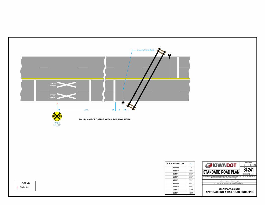
POSTED SPEED LIMIT L
325'25 MPH
40 MPH
35 MPH
30 MPH 460'
990'
1100'
1200'
885'
565'
670'
775'
55 MPH
50 MPH
45 MPH
60 MPH
65 MPH
LEGEND
Traffic Sign
L min. 8'
R R
36" x 36"
W10-1
Crossing Signal (typ.)
FOUR-LANE CROSSING WITH CROSSING SIGNAL
SI-241
REVISION
10-18-16
SHEET 2 of 2
REVISIONS:Replaced old Iowa DOT logo with new logo.Changed No Passing Zone sign size from 48" x 60" x 60" to 48" x 64" to 64".
APPROVED BY DESIGN METHODS ENGINEER
STANDARD ROAD PLAN
1
APPROACHING A RAILROAD CROSSING
SIGN PLACEMENT

W4-2M W8-11A W21-9
W21-3AW20-1A
18
7
18.21 28.98
57
16.53 32.34
57
20.45 24.5
18.21
16.53
20.45
16.4
65.4
65.4
W20-1A;
48.00" across sides 3.00" Radius, 1.25" Border, 0.75" Indent, Black on Orange;
[TRUCKS] C 2K; [TURNING] C 2K;
[AHEAD] C 2K;
TRUCKS
TURNING
AHEAD
15
7
20.59 24.22
57
20.45 24.5
57
17.65 30.1
20.59
20.45
17.65
19.4
65.4
65.4
W20-1A;
48.00" across sides 3.00" Radius, 1.25" Border, 0.75" Indent, Black on Orange;
[RAMP] D 2K; [WORK] D 2K; [AHEAD] D 2K;
RAMP
AHEAD
WORK
21
8
17.66 30.08
68
14.58 36.24
17.66
14.58
22.4
65.4
65.4
W21-9;
48.00" across sides 3.00" Radius, 1.25" Border, 0.75" Indent, Black on Orange;
[AERIAL] C 2K; [SEEDING] C 2K;
AERIAL
SEEDING
12
8
24.62 16.16
68
16.06 33.28
68
19.42 26.56
24.62
16.06
19.42
17.4
65.4
65.4
W8-11A;
48.00" across sides 3.00" Radius, 1.25" Border, 0.75" Indent, Black on Orange;
[END] C 2K; [UNEVEN] C 2K; [LANES] C 2K;
END
UNEVEN
LANES
22
10
15 35.4
513.5
18.07 29.25
15
18.08
14.9
65.4
65.4
W4-2M;
48.00" across sides 3.00" Radius, 1.25" Border, 0.75" Indent, Black on Orange;
[MERGE] C 2K;
Standard Arrow Custom 29.25" X 13.50" 180{;
MERGE
SI-881
REVISION
10-17-17
SHEET 1 of 4
REVISIONS:Added RUMBLE STRIPS AHEAD sign to page 4.
APPROVED BY DESIGN METHODS ENGINEER
STANDARD ROAD PLAN
5
SPECIAL SIGNS FOR WORKZONES

G20-22
G20-23A
G20-23
G20-24
G20-25
G20-21A
G20-21
210
0.916.2
0.9
214
18
G20-21A;
No border, Black on Orange;
[00] D 2K;
00
7.2
510
10.7 24.1 10 27.2 10 51.3
7.5
10
19.95 30.2
22.7
514
10 18
24.7
510
10 35.9
10.7
19.95
7.2
5
5.2
57.2
5
42
144
2.25" Radius, 0.88" Border, 0.63" Indent, Black on Orange;
[TWO WAY TRAFFIC] D 2K; [NEXT] D 2K; G20-21A; [MILES] D 2K;
NEXT MILES
TWO WAY TRAFFIC
7.2
510
20.7 30.6
7.5
10
8.8 28.6 10 15.8
20.7
8.8
7.2
5
42
72
2.25" Radius, 0.88" Border, 0.63" Indent, Black on Orange;
[EXIT] E 2K; [500 FT] E 2K;
EXIT
500 FT
6.6
610
8.7 30.6
519.6
8
14.16 19.68
8.7
14.16
6.6
6
48
48
G20-23;
1.25" Border, 0.75" Indent, Black on Orange;
[EXIT] E 2K; Arrow 80 - 25.00" 45{;
28
2.4820.24 4 6.8
2.48
212
36
G20-23A;
0.63" Border, 0.38" Indent, Black on Orange;
[000 A] D 2K;
EXIT
000 A
46
9.93 14.82 6 19.32
46
4.0520.1 6 25.8
9.93
4.05
4
24
60
1.50" Radius, 0.63" Border, 0.38" Indent, Black on Orange;
[ONE LANE] D 2K; [ROAD AHEAD] D 2K;
ONE LANE
ROAD AHEAD
2.5
4
5.045.324 7.92 4 16.68
34
4.029.12 4 11.84 4 11
5.04
4.02
2.5
16
48
1.50" Radius, 0.63" Border, 0.38" Indent, Black on Orange;
[DO NOT FOLLOW] C 2K;
[INTO WORK AREA] C 2K;
DO NOT FOLLOW
INTO WORK AREA
SI-881
REVISION
10-17-17
SHEET 2 of 4
REVISIONS:Added RUMBLE STRIPS AHEAD sign to page 4.
APPROVED BY DESIGN METHODS ENGINEER
STANDARD ROAD PLAN
5
SPECIAL SIGNS FOR WORKZONES
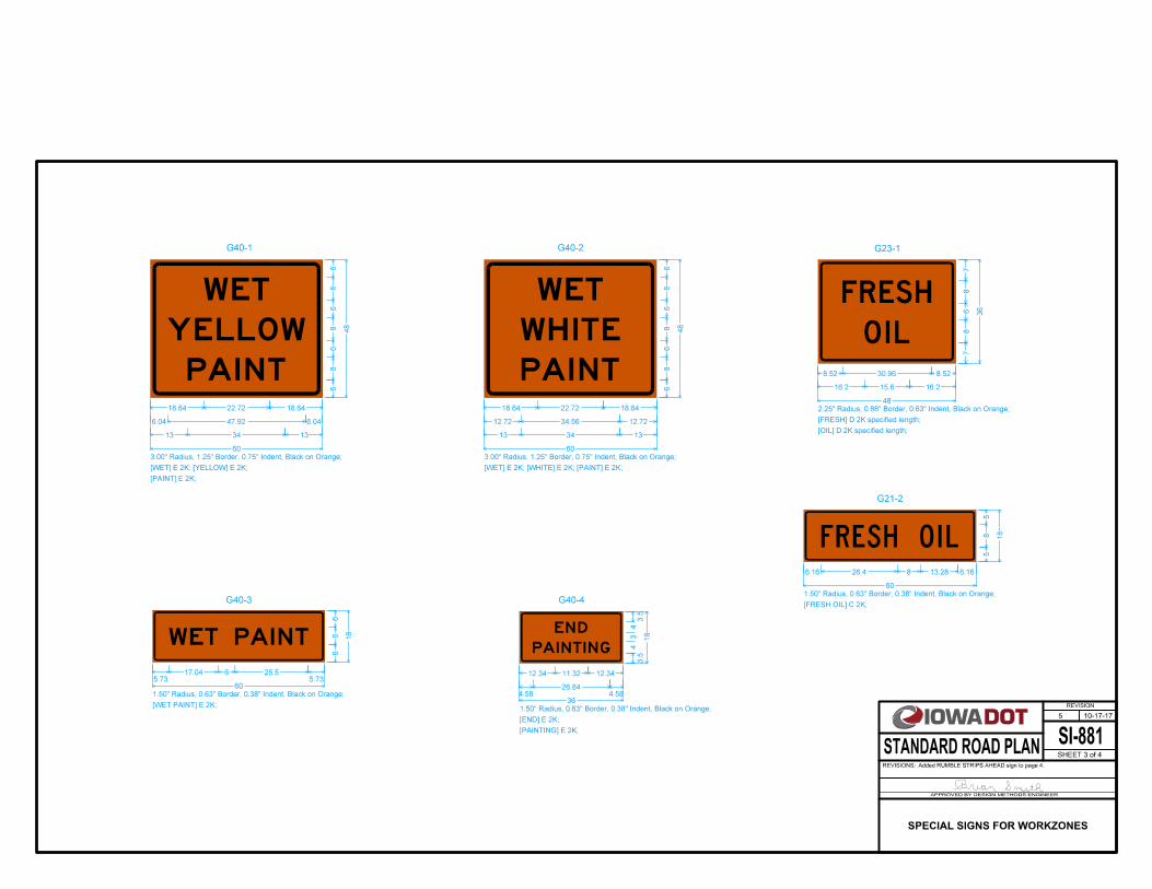
G40-1
G40-3
G40-2
G40-4
G23-1
G21-2
58
6.16 26.4 8 13.28 6.16
5
18
60
1.50" Radius, 0.63" Border, 0.38" Indent, Black on Orange;
[FRESH OIL] C 2K;
FRESH OIL
78
8.52 30.96
68
16.2 15.6
8.52
16.2
7
36
48
2.25" Radius, 0.88" Border, 0.63" Indent, Black on Orange;
[FRESH] D 2K specified length;
[OIL] D 2K specified length;
FRESH
OIL6
8
18.64 22.72
68
6.04 47.92
68
13 34
18.64
6.04
13
6
48
60
3.00" Radius, 1.25" Border, 0.75" Indent, Black on Orange;
[WET] E 2K; [YELLOW] E 2K;
[PAINT] E 2K;
W ET
Y ELLOW
PAINT
68
18.64 22.72
68
12.72 34.56
68
13 34
18.64
12.72
13
6
48
60
3.00" Radius, 1.25" Border, 0.75" Indent, Black on Orange;
[WET] E 2K; [WHITE] E 2K; [PAINT] E 2K;
W ET
W HITE
PAINT
66
5.7317.04 6 25.5
5.73
6
18
60
1.50" Radius, 0.63" Border, 0.38" Indent, Black on Orange;
[WET PAINT] E 2K;
W ET PAINT3.5
4
12.34 11.32
34
4.5826.84
12.34
4.58
3.5
18
36
1.50" Radius, 0.63" Border, 0.38" Indent, Black on Orange;
[END] E 2K;
[PAINTING] E 2K;
END
PAINTING
SI-881
REVISION
10-17-17
SHEET 3 of 4
REVISIONS:Added RUMBLE STRIPS AHEAD sign to page 4.
APPROVED BY DESIGN METHODS ENGINEER
STANDARD ROAD PLAN
5
SPECIAL SIGNS FOR WORKZONES

SI-881
REVISION
10-17-17
SHEET 4 of 4
REVISIONS:Added RUMBLE STRIPS AHEAD sign to page 4.
APPROVED BY DESIGN METHODS ENGINEER
STANDARD ROAD PLAN
5
SPECIAL SIGNS FOR WORKZONES
RUMBLE
STRIPS
AHEAD
17.7 30
19.9 25.6
20.4 24.5
17.7
19.9
20.5
65.4
W20-9;
48.0" across sides 3.0" Radius, 1.3" Border, 0.8" Indent, Black on Orange;
[RUMBLE] C 2K; [STRIPS] C 2K; [AHEAD] C 2K;
18.7
75
75
715.7
65.4
W20-9

G20-52
G20-53
G20-54 G20-55
G20-58 G20-59
1
1
G20-51
TC-81 for requirement of restricted width dimension.See TC-81
7.4
8
8.7 59 8 29.6
412
36 42
212
11.4 12
35.4
8
8 28.8 8 34.4
41.2
8.7 96.6
68
17.6 18.6 8 24.2 8 20
8.7
36
11.4
8.7
17.6
7.4
28.6
72
114
3.0" Radius, 1.3" Border, 0.8" Indent, Black on Orange;
[RESTRICTED WIDTH] D 2K; [MILES AHEAD] D 2K; [USE NEXT EXIT] D 2K;
Width Panel G20-58
G20-59
RESTRICTED WIDTH
MILES AHEAD
USE NEXT EXIT
68
8.7 59 8 29.6
412
36 42
212
11.4 12
34
8
8 28.8 8 34.4
8.7
36
11.4
4 6
48
114
3.0" Radius, 1.3" Border, 0.8" Indent, Black on Orange;
[RESTRICTED WIDTH] D 2K; [MILES AHEAD] D 2K;
Width Panel G20-58
G20-59
RESTRICTED WIDTH
MILES AHEAD
68
15.8 23.6 8 32.8
68
10.1 25.8
18
12
8 42
68
21.3 20 8 25.4
15.8
10.1
21.3
6
18
48
96
3.0" Radius, 1.3" Border, 0.8" Indent, Black on Orange;
[WIDE LOADS] D 2K; [OVER] D 2K; [EXIT HERE] D 2K;
Width Panel G20-58
WIDE LOADS
OVER
EXIT HERE
68
19.7 12.9 8 23.7
68
8.7 32.8 8 25.8
412
21 42
19.7
8.7
21
4
48
84
3.0" Radius, 1.3" Border, 0.8" Indent, Black on Orange;
[NO WIDE] D 2K; [LOADS OVER] D 2K;
Width Panel G20-58
NO WIDE
LOADS OVER
68
15.5 59
68
9 29.6 8 34.4
412
24 42
15.5
9
24
4
48
90
3.0" Radius, 1.3" Border, 0.8" Indent, Black on Orange;
[RESTRICTED] D 2K; [WIDTH AHEAD] D 2K;
Width Panel G20-58
RESTRICTED
WIDTH AHEAD
28
2.115.9 4
2.84 11.1
2.1
212
42
No border, Orange;
[44'] Black D 2K;
[-] Black D 2K;
[4"] Black D 2K;
44'-4"
28
3 6 3
212
12
No border, Orange;
[4] Black D 2K;
4SI-882
REVISION
10-18-16
SHEET 1 of 2
REVISIONS:Replaced old Iowa DOT logo with new logo.
APPROVED BY DESIGN METHODS ENGINEER
STANDARD ROAD PLAN
1
TRAFFIC CONTROL ZONES
SPECIAL SIGNS FOR RESTRICTED WIDTH

G20-52A G20-53A G20-54A
G20-55A G20-58A G20-59A
1
1
26
0.811.9 3
2.13 8.4
0.8
210
30
No border, Orange;
[44'] Black D 2K;
[-] Black D 2K;
[4"] Black D 2K;
44'-4"
26
2.84.52.7
210
10
No border, Orange;
[4] Black D 2K;
4
4.5
68.8 44.2 6 22.2
2.5
10
30 30
0.5
10
10.3 10
25.5
6
6 21.6 6 25.8
8.8
30
10.3
2.5 4.5
36
90
2.3" Radius, 0.9" Border, 0.6" Indent, Black on Orange;
[RESTRICTED WIDTH] D 2K; [MILES AHEAD] D 2K;
G20-58A
G20-59A
RESTRICTED WIDTH
MILES AHEAD
4.5
6
11.8 17.8 6 24.6
4.5
6
8.3 19.4
13
10
6 30
4.5
6
16 15 6 19
11.8
8.3
16
4.5
13
36
72
2.3" Radius, 0.9" Border, 0.6" Indent, Black on Orange;
[WIDE LOADS] D 2K; [OVER] D 2K;
[EXIT HERE] D 2K;
G20-58A
EXIT HERE
WIDE LOADS
OVER
4.5
6
16.3 9.7 6 17.7
4.5
6
8 24.6 6 19.4
2.5
10
18 30
16.3
8
18
2.5
36
66
2.3" Radius, 0.9" Border, 0.6" Indent, Black on Orange;
[NO WIDE] D 2K; [LOADS OVER] D 2K;
G20-58A
NO WIDE
LOADS OVER
4.5
6
10.9 44.2
4.5
6
6 22.2 6 25.8
2.5
10
18 30
10.9
6
18
2.5
36
66
2.3" Radius, 0.9" Border, 0.6" Indent, Black on Orange;
[RESTRICTED] D 2K; [WIDTH AHEAD] D 2K;
G20-58A
RESTRICTED
WIDTH AHEAD
TC-81 for requirement of restricted width dimension.See TC-81
SI-882
REVISION
10-18-16
SHEET 2 of 2
REVISIONS:Replaced old Iowa DOT logo with new logo.
APPROVED BY DESIGN METHODS ENGINEER
STANDARD ROAD PLAN
1
TRAFFIC CONTROL ZONES
SPECIAL SIGNS FOR RESTRICTED WIDTH