sii9533 port processor
TRANSCRIPT

SiI9533 Port Processor
Data Sheet
SiI-DS-1128-C
March 2016
Downloaded From Oneyac.com

SiI9533 Port Processor Data Sheet
© 2012-2016 Lattice Semiconductor Corp. All Lattice trademarks, registered trademarks, patents, and disclaimers are as listed at www.latticesemi.com/legal. All other brand or product names are trademarks or registered trademarks of their respective holders. The specifications and information herein are subject to change without notice.
2 SiI-DS-1128-C
Contents 1. General Description ...................................................................................................................................................... 5
HDMI Inputs and Outputs ................................................................................................................................... 5 1.1. Performance Improvement Features .................................................................................................................. 5 1.2. Audio Inputs and Outputs ................................................................................................................................... 6 1.3. ESD and Latch-up................................................................................................................................................. 6 1.4. Control Capability ................................................................................................................................................ 6 1.5. Packaging............................................................................................................................................................. 6 1.6.
2. Functional Description .................................................................................................................................................. 7 Always-on Section ............................................................................................................................................... 7 2.1.
Serial Ports Block............................................................................................................................................. 8 2.1.1. Static RAM Block ............................................................................................................................................. 8 2.1.2. NVRAM Block .................................................................................................................................................. 8 2.1.3. HDCP Registers Block ...................................................................................................................................... 8 2.1.4. OTP ROM Block ............................................................................................................................................... 8 2.1.5. Booting Sequencer .......................................................................................................................................... 9 2.1.6. Configuration, Status, and Interrupt Control Block ........................................................................................ 9 2.1.7. Mobile HD Control Block ................................................................................................................................. 9 2.1.8. CEC Interface Controller.................................................................................................................................. 9 2.1.9.
Power Block ................................................................................................................................................ 9 2.1.10. Power-down Section ........................................................................................................................................... 9 2.2.
TMDS Receiver Blocks ..................................................................................................................................... 9 2.2.1. Input Multiplexer Blocks A, B, C, D, and E ....................................................................................................... 9 2.2.2. HDMI, MHL, and InstaPort S Receiver Blocks ............................................................................................... 10 2.2.3. Video/Audio Splitter Block ............................................................................................................................ 10 2.2.4. InstaPrevue Block .......................................................................................................................................... 10 2.2.5. Stream Mixer Block ....................................................................................................................................... 10 2.2.6. Video Pattern Generator Block ..................................................................................................................... 10 2.2.7. Audio Sampling Rate Converter Block .......................................................................................................... 11 2.2.8. Audio Input Block .......................................................................................................................................... 11 2.2.9.
Audio Output Block .................................................................................................................................. 12 2.2.10. Audio Return Channel Input and Output .................................................................................................. 12 2.2.11. TMDS Transmitter Block ........................................................................................................................... 12 2.2.12.
3. Electrical Specifications .............................................................................................................................................. 13 Absolute Maximum Conditions ......................................................................................................................... 13 3.1. Normal Operating Conditions ........................................................................................................................... 13 3.2. DC Specifications ............................................................................................................................................... 14 3.3. AC Specifications ............................................................................................................................................... 16 3.4.
Control Signal Timing Specifications ............................................................................................................. 17 3.4.1. Audio Input Timing ........................................................................................................................................ 18 3.4.2. Audio Output Timing ..................................................................................................................................... 19 3.4.3.
4. Timing Diagrams ......................................................................................................................................................... 20 Reset Timing Diagrams ...................................................................................................................................... 20 4.1. I
2C Timing Diagram ............................................................................................................................................ 20 4.2.
Digital Audio Input Timing ................................................................................................................................. 21 4.3. Digital Audio Output Timing .............................................................................................................................. 22 4.4.
5. Pin Diagram and Pin Description ................................................................................................................................ 23 Pin Diagram ....................................................................................................................................................... 23 5.1. Pin Descriptions ................................................................................................................................................. 24 5.2.
HDMI Receiver and MHL Port Pins ................................................................................................................ 24 5.2.1. HDMI Transmitter Port Pins .......................................................................................................................... 24 5.2.2. Audio Pins ..................................................................................................................................................... 25 5.2.3. CEC Pin .......................................................................................................................................................... 26 5.2.4.
Downloaded From Oneyac.com

SiI9533 Port Processor Data Sheet
© 2012-2016 Lattice Semiconductor Corp. All Lattice trademarks, registered trademarks, patents, and disclaimers are as listed at www.latticesemi.com/legal. All other brand or product names are trademarks or registered trademarks of their respective holders. The specifications and information herein are subject to change without notice.
SiI-DS-1128-C 3
Configuration Pins ......................................................................................................................................... 26 5.2.5. Control Pins ................................................................................................................................................... 26 5.2.6. Crystal Pins .................................................................................................................................................... 27 5.2.7. DDC I
2C Pins .................................................................................................................................................. 27 5.2.8.
System Switching Pins ................................................................................................................................... 28 5.2.9. Power and Ground Pins ............................................................................................................................ 28 5.2.10. Reserved ................................................................................................................................................... 28 5.2.11.
6. Feature Information ................................................................................................................................................... 29 Standby and HDMI Port Power Supplies ........................................................................................................... 29 6.1. InstaPort S ......................................................................................................................................................... 30 6.2. InstaPrevue ....................................................................................................................................................... 30 6.3. MHL Receiver .................................................................................................................................................... 31 6.4. 3D Video Formats .............................................................................................................................................. 31 6.5.
7. Design Recommendations .......................................................................................................................................... 33 Power Supply Decoupling ................................................................................................................................. 33 7.1. Power Supply Control Timing and Sequencing ................................................................................................. 33 7.2.
8. Package Information ................................................................................................................................................... 34 ePad Requirements ........................................................................................................................................... 34 8.1. Package Dimensions .......................................................................................................................................... 35 8.2. Marking Specification ........................................................................................................................................ 36 8.3. Ordering Information ........................................................................................................................................ 36 8.4.
References .......................................................................................................................................................................... 37 Standards Documents ..................................................................................................................................................... 37 Lattice Semiconductor Documents ................................................................................................................................. 37
Revision History .................................................................................................................................................................. 38
Figures Figure 1.1. Typical HTiB Application ..................................................................................................................................... 5 Figure 1.2. Typical SoundBar Application ............................................................................................................................. 6 Figure 2.1. Functional Block Diagram ................................................................................................................................... 7 Figure 2.2. I
2C Control Mode Configuration ......................................................................................................................... 8
Figure 3.1. Test Point VDDTP for AVDD33 Noise Tolerance Specification .......................................................................... 14 Figure 3.2. Audio Crystal Schematic ................................................................................................................................... 18 Figure 4.1. Conditions for Use of RESET_N ......................................................................................................................... 20 Figure 4.2. RESET_N Minimum Timing ............................................................................................................................... 20 Figure 4.3. I
2C Data Valid Delay, Driving Read Cycle Data .................................................................................................. 20
Figure 4.4. I2S Input Timing ................................................................................................................................................. 21
Figure 4.5. S/PDIF Input Timing .......................................................................................................................................... 21 Figure 4.6. I
2S Output Timing .............................................................................................................................................. 22
Figure 4.7. S/PDIF Output Timing ....................................................................................................................................... 22 Figure 4.8. MCLK Timing ..................................................................................................................................................... 22 Figure 5.1. Pin Diagram ....................................................................................................................................................... 23 Figure 6.1. Standby Power Supply Diagram ........................................................................................................................ 29 Figure 7.1. Decoupling and Bypass Schematic Diagram ..................................................................................................... 33 Figure 7.2. Decoupling and Bypass Capacitor Placement ................................................................................................... 33 Figure 8.1. Package Diagram .............................................................................................................................................. 35 Figure 8.2. Marking Diagram .............................................................................................................................................. 36
Downloaded From Oneyac.com

SiI9533 Port Processor Data Sheet
© 2012-2016 Lattice Semiconductor Corp. All Lattice trademarks, registered trademarks, patents, and disclaimers are as listed at www.latticesemi.com/legal. All other brand or product names are trademarks or registered trademarks of their respective holders. The specifications and information herein are subject to change without notice.
4 SiI-DS-1128-C
Tables Table 2.1. Pixel Clock Source and Frequency ...................................................................................................................... 11 Table 3.1. Absolute Maximum Conditions .......................................................................................................................... 13 Table 3.2. Normal Operating Conditions ............................................................................................................................ 13 Table 3.3. Digital I/O DC Specifications ............................................................................................................................... 14 Table 3.4. TMDS Input DC Specifications – HDMI Mode .................................................................................................... 14 Table 3.5. TMDS Input DC Specifications – MHL Mode ...................................................................................................... 14 Table 3.6. TMDS Output DC Specifications ......................................................................................................................... 15 Table 3.7. Single Mode Audio Return Channel DC Specifications ....................................................................................... 15 Table 3.8. S/PDIF Input Port DC Specifications ................................................................................................................... 15 Table 3.9. CEC DC Specifications ......................................................................................................................................... 15 Table 3.10. CBUS DC Specifications .................................................................................................................................... 15 Table 3.11. Power Requirements ........................................................................................................................................ 16 Table 3.12. TMDS Input Timing AC Specifications – HDMI Mode ....................................................................................... 16 Table 3.13. TMDS Input Timing AC Specifications – MHL Mode......................................................................................... 16 Table 3.14. TMDS Output Timing AC Specifications ........................................................................................................... 16 Table 3.15. Single Mode Audio Return Channel AC Specifications ..................................................................................... 17 Table 3.16. CEC AC Specifications ....................................................................................................................................... 17 Table 3.17. CBUS AC Specifications .................................................................................................................................... 17 Table 3.18. Control Signal Timing Specifications ................................................................................................................ 17 Table 3.19. Audio Crystal Frequency .................................................................................................................................. 18 Table 3.20. S/PDIF Input Port AC Specifications ................................................................................................................. 18 Table 3.21. I
2S Input Port AC Specifications ........................................................................................................................ 18
Table 3.22. I2S Output Port AC Specifications ..................................................................................................................... 19
Table 3.23. S/PDIF Output Port AC Specifications .............................................................................................................. 19 Table 6.1. Description of Power Modes .............................................................................................................................. 29 Table 6.2. Supported Combinations of Main Video and InstaPreview Displays ................................................................. 30 Table 6.3. Supported 3D Video Formats ............................................................................................................................. 32
Downloaded From Oneyac.com

SiI9533 Port Processor Data Sheet
© 2012-2016 Lattice Semiconductor Corp. All Lattice trademarks, registered trademarks, patents, and disclaimers are as listed at www.latticesemi.com/legal. All other brand or product names are trademarks or registered trademarks of their respective holders. The specifications and information herein are subject to change without notice.
SiI-DS-1128-C 5
1. General Description The Lattice Semiconductor SiI9533 Port Processor is the latest HDMI® port processor targeted at Home Theater in a Box (HTiB), and Soundbar applications. The port processor features InstaPort™ S and InstaPrevue™ technologies, Mobile High-Definition Link 2.1 (MHL®), 300 MHz HDMI, and Audio Return Channel (ARC).
MHL allows the user to attach a device to the HTiB or soundbar and view high-definition content while the mobile device battery is charging. MHL 2.1 supports 3D and PackedPixel Mode (PPM) in SiI9533 port processor and is supported on two input ports.
The SiI9533 port processor offers an extensive set of audio features, including audio extraction and insertion. Multi-channel audio from the active HDMI input can be extracted and sent to the audio output port. Additionally, a 2-channel PCM or bitstream audio from an audio DSP or an SoC can be inserted and sent to the HDMI output.
The SiI9533 device supports an ARC transceiver. ARC transceivers is configurable as either ARC receiver or ARC transmitter. As an ARC receiver in an AVR or HTiB design, the transmitter HDMI output can receive an ARC signal from a Digital Television (DTV). The ARC channel is configurable as an ARC transmitter and data from an S/PDIF output can be routed to the ARC transmitter.
HDMI Inputs and Outputs 1.1. Three 300 MHz HDMI input ports and one output
port
3.0 Gb/s TMDS™ cores
HDMI, MHL, HDCP 1.4, and DVI compatible
Supports video resolutions up to 8-bit 4K @ 30 Hz, 12-bit 1080p @ 60 Hz, or 12-bit 720p/1080i @ 120 Hz
HDMI 2.0 Specification format supports 4K @ 50/60 Hz (when Pixel Encoding method is YCbCr 4:2:0 and InstaPrevue is disabled).
Supports all mandatory and some optional 3D formats up to 300 MHz
Supports up to1080p @ 60 Hz on two MHL input ports
Supports 3D video in MHL mode
Preprogrammed with HDCP keys
Repeater function supports up to 127 devices
Performance Improvement 1.2.Features
InstaPort S viewing technology reduces port switching time to less than one second
InstaPrevue technology provides a Picture-in-Picture (PIP) preview of connected source devices
AVI, Audio InfoFrame, and video input resolution detection for all input ports, accessible port-by-port
Hardware-based HDCP error detection and recovery minimizes firmware intervention
Automatic output mute and unmute based on link stability, such as cable connect/detach
Figure 1.1. Typical HTiB Application
Downloaded From Oneyac.com

SiI9533 Port Processor Data Sheet
© 2012-2016 Lattice Semiconductor Corp. All Lattice trademarks, registered trademarks, patents, and disclaimers are as listed at www.latticesemi.com/legal. All other brand or product names are trademarks or registered trademarks of their respective holders. The specifications and information herein are subject to change without notice.
6 SiI-DS-1128-C
Audio Inputs and Outputs 1.3. S/PDIF input and output support PCM and
compressed audio formats up to 192 kHz, such as Dolby® Digital, DTS and AC-3
DSD output supports Super Audio CD applications, up to six channels
I2S output supports PCM and DVD-audio output,
up to eight channels at 192 kHz
I2S inputs support PCM and DVD-audio input, up to
two channels at 192 kHz
High bitrate audio output support, such as DTS-HD Master Audio™ and Dolby TrueHD
Sample Rate Converter (SRC) support for downsampling 2:1 and 4:1
One ARC input or output support
ESD and Latch-up 1.4.
Conforming to JEDEC standards
Control Capability 1.5. One Consumer Electronics Control (CEC) interface
with CEC I/O to support an HDMI device
Individual control of Hot Plug Detect (HPD) for every input port
Achieved through the local I2C bus
Packaging 1.6.
88-pin, 10 mm × 10 mm, 0.4 mm pitch QFN package with an ePad
Figure 1.2. Typical SoundBar Application
Downloaded From Oneyac.com

SiI9533 Port Processor Data Sheet
© 2012-2016 Lattice Semiconductor Corp. All Lattice trademarks, registered trademarks, patents, and disclaimers are as listed at www.latticesemi.com/legal. All other brand or product names are trademarks or registered trademarks of their respective holders. The specifications and information herein are subject to change without notice.
SiI-DS-1128-C 7
2. Functional Description Figure 2.1 shows the block diagram of the SiI9533 port processor.
M
U
X
Power-down Section
R0X
R1X
R2X
M
U
X
ARC
Channel
ARC RX_TX
I2S/SPDIF/DSD
I2S/SPDIF
HDCP
Decryption M
U
X
TXHDMI Tx
Encode HDCP
Encode TMDS
Mobile HD
Control
HDCP
Registers Rx OTP
EDID SRAMNVRAM Booting
Sequencer
Configuration, Status
and Interrupt Control
Registers
DDC0
DDC1
DDC2
Local
I2C
Always-on Section
DDC
I2C INT
CBUS/HPD
Serial PortsCBUS0
CBUS1
TPI HW
DDC TX
Power
RnPWR5V
SBVCC5V
HDMI/MHL
Receiver
InstaPort
TMDS Rx
(Port0)
TMDS Rx
(Port1) SRC
Video
Pattern
Generator
A
B
C
D
HDMI/MHL
Receiver
InstaPort
Video Audio
Splitter
E
Main
Pipe
Roving
Pipe
Tx HDCP
Audio Input
Multi-Channel
Audio Output
M
U
X
M U XTMDS Rx
(Port2)
InstaPrevue
Stream Mixer
CEC Interface
Controller
CEC
Tx OTP
Audio
Mixer
Figure 2.1. Functional Block Diagram
Always-on Section 2.1.
The Always-on section contains the low-speed control circuits of the HDMI connection, the I2C interfaces, internal
memory blocks, and the registers that control the blocks of the Always-on section.
Downloaded From Oneyac.com

SiI9533 Port Processor Data Sheet
© 2012-2016 Lattice Semiconductor Corp. All Lattice trademarks, registered trademarks, patents, and disclaimers are as listed at www.latticesemi.com/legal. All other brand or product names are trademarks or registered trademarks of their respective holders. The specifications and information herein are subject to change without notice.
8 SiI-DS-1128-C
Serial Ports Block 2.1.1.
The Serial Ports block provides four I2C serial interfaces: three DDC ports to communicate with the HDMI or DVI hosts,
and one local I2C port for initialization and control by a local microcontroller in the HTiB, soundbar or display. Each
interface is 5 V tolerant. Figure 2.2 shows the connection of the local I2C port to the system microcontroller.
Port ProcessorSystem
Microcontroller
INT
AVDD33/Standby Power
SiI9533CSDA
CSCL
Figure 2.2. I2C Control Mode Configuration
The three DDC interfaces (DDC 0–2) on the SiI9533 port processor are slave interfaces that can run up to 400 kHz. Each interface connects to one E-DDC bus and is used to read the integrated EDID and HDCP authentication information. The port is accessible on the E-DDC bus at device addresses 0xA0, for EDID and 0x74, for HDCP control. The transmitter DDC master controller supports accessing HDCP and EDID up to 100 kHz. Local I
2C can also access the transmitter DDC bus in
bypass mode in which case the local I2C clock becomes the clock source.
Static RAM Block 2.1.2.
The Static RAM (SRAM) block contains 1792 bytes of RAM. Each port is allocated a 256-byte block for DDC; this allows all ports to be read simultaneously from three different sources connected to the SiI9533 device. 640 bytes are available for the Key Selection Vectors (KSVs), while 128 bytes are used for auto-boot feature. The remaining bytes are unused. Every EDID and SHA KSV has an offset location. The SRAM is written to and read from using the local I
2C interface and can also
be read through the DDC interface. The memory is read through the DDC interface using only 5 V power from the HDMI connector.
NVRAM Block 2.1.3.
The port processor contains 512 bytes of NVRAM. Of these, 256 bytes are used to store common EDID data used by each of the ports, 128 bytes are used by the auto-boot feature, and 128 bytes are unused. Both the NVRAM EDID data and NVRAM auto-boot data should be initialized by software using the local I
2C bus at least once during manufacture.
HDCP Registers Block 2.1.4.
The HDCP Registers block controls the necessary logic to decrypt the incoming audio and video data. The decryption process is controlled entirely by the host-side microcontroller, using a set sequence of register reads and writes through the local I
2C channel. The decryption process uses preprogrammed HDCP keys and a Key Selection Vector (KSV)
stored in the on-chip nonvolatile memory.
OTP ROM Block 2.1.5.
The One-time Programmable (OTP) ROM block of the receiver is programmed at the factory, and contains the preprogrammed HDCP keys. System manufacturers do not need to purchase key sets from Digital Content Protection, LLC. Lattice Semiconductor handles all purchasing, programming, and security for the HDCP keys. The preprogrammed HDCP keys provide the highest level of security possible, as keys cannot be read out of the device after they are programmed.
Downloaded From Oneyac.com

SiI9533 Port Processor Data Sheet
© 2012-2016 Lattice Semiconductor Corp. All Lattice trademarks, registered trademarks, patents, and disclaimers are as listed at www.latticesemi.com/legal. All other brand or product names are trademarks or registered trademarks of their respective holders. The specifications and information herein are subject to change without notice.
SiI-DS-1128-C 9
Booting Sequencer 2.1.6.
The booting sequencer boots the required data, such as EDID, initial HPD status, and MHL port selection from NVRAM during power on.
Configuration, Status, and Interrupt Control Block 2.1.7.
The Configuration, Status, and Interrupt Control Registers block contains registers required for configuring and managing the SiI9533 device features. The registers are used to perform audio, video, and auxiliary format processing. The registers are also used for HDMI InfoFrame packet format and power-down control. The registers are accessible from the local I
2C port. This block also handles interrupt operation.
Mobile HD Control Block 2.1.8.
The Mobile HD Control block handles MHL DDC control. This block handles CBUS conversion to DDC signals for accessing the EDID and HDCP interface blocks.
CEC Interface Controller 2.1.9.
The Consumer Electronics Control (CEC) Interface Controller provides a CEC-compliant signal, and has a high-level register interface accessible through the I
2C interface. Programming is done through the Lattice Semiconductor CEC
Programming Interface (CPI). This controller makes CEC control easy and straightforward as the host processor is not required to perform these low-level transactions on the CEC bus. CEC pass-through mode is therefore neither required nor supported.
Power Block 2.1.10.
The Power block features an analog power multiplexer with inputs from the +5 V power from the R[0-2]PWR5V and the SBVCC5V sources. The output of the analog power multiplexer supplies power to the Always-on section.
Power-down Section 2.2.
The Power-down section contains the HDMI high-speed data paths, the analog TMDS input and output blocks, and the digital logic for HDMI data and HDCP processing.
TMDS Receiver Blocks 2.2.1.
The TMDS Receiver blocks, defined as Port 0, Port 1, and Port 2, are terminated separately, equalized under the control of the receiver digital block, and controlled by the local I
2C bus. Input data is oversampled by five to enable the
downstream DPLL block to capture the most stable signal.
Input Multiplexer Blocks A, B, C, D, and E 2.2.2.
There are three 3:1 Input Multiplexer blocks (A, B, and C) and two 2:1 Input Multiplexer blocks (D and E) in the SiI9533 port processor.
Input Multiplexer Block A selects one of the three TMDS inputs and sends it to the main pipe. Input Multiplexer Block B selects one of the three TMDS inputs and sends it to the roving pipe. Input Multiplexer Block C selects either main pipe or video pattern generator source and sends it to HDMI transmitter.
The specific function of the multiplexers is determined by whether InstaPort S or InstaPrevue is enabled. In InstaPort S or InstaPrevue modes, Multiplexer Block A selects the active input and sends it to the main pipe for processing. Multiplexer Block B sequentially selects one of the two inactive input signals and sends it to the InstaPort S or InstaPrevue blocks for processing.
Input Multiplexer Block D selects the decoded audio stream from the TMDS input of main pipe or the roving pipe, and sends it to Audio Output block.
Downloaded From Oneyac.com

SiI9533 Port Processor Data Sheet
© 2012-2016 Lattice Semiconductor Corp. All Lattice trademarks, registered trademarks, patents, and disclaimers are as listed at www.latticesemi.com/legal. All other brand or product names are trademarks or registered trademarks of their respective holders. The specifications and information herein are subject to change without notice.
10 SiI-DS-1128-C
Input Multiplexer Block E selects either the inserted audio, or the audio coming from the Multiplexer Block D, and sends it to the transmitter.
HDMI, MHL, and InstaPort S Receiver Blocks 2.2.3.
The HDMI, MHL, and InstaPort S receiver blocks perform:
Deskewing
Analyzing packets
Processing the main and roving pipes
Multiplexing
Repeater functions
HDCP authentication
The SiI9533 device supports three 300 MHz HDMI input ports. MHL can be enabled on any two input ports, selected at the time of manufacture, by programming a register in the NVRAM.
Video/Audio Splitter Block 2.2.4.
The Video/Audio Splitter block separates the video and audio data from the TMDS stream for the roving pipe. The video is sent to the InstaPrevue Block and the audio is sent to Multiplexer Block D. This can be used in the InstaPrevue Picture-in-Picture (PIP) mode, in which a single subwindow is displayed on the main video. The audio from the subwindow replaces the audio from the main video before it is sent to the transmitter.
InstaPrevue Block 2.2.5.
The InstaPrevue block captures and processes all of the preauthenticated HDMI/DVI/MHL subframe images from the roving pipe. The operating preview mode is configured in this block.
Stream Mixer Block 2.2.6.
The Stream Mixer block replaces a region of the main port video with a subframe image from the InstaPrevue block. It merges subframes with the main video input at the proper screen locations specified by external software register settings.
Video Pattern Generator Block 2.2.7.
The Video Pattern Generator (VPG) block supplies one of eight predefined video patterns to the HDMI transmitter. The predefined video patterns include:
Solid red
Solid green
Solid blue
Solid black
Solid white
Ramp
8 × 6 chessboard
Color bars
The resolutions of the video patterns in the RGB color space are: 480p, 576p, 720p @ 50/60 Hz, and 1080p @ 50 Hz video resolutions.
An example use of the VPG is to combine the predefined video pattern with an external audio input to create a complete HDMI stream, which can then be sent from the HDMI transmitter to a soundbar. The VPG can be used for test purposes during product development.
Downloaded From Oneyac.com

SiI9533 Port Processor Data Sheet
© 2012-2016 Lattice Semiconductor Corp. All Lattice trademarks, registered trademarks, patents, and disclaimers are as listed at www.latticesemi.com/legal. All other brand or product names are trademarks or registered trademarks of their respective holders. The specifications and information herein are subject to change without notice.
SiI-DS-1128-C 11
The VPG requires a pixel clock for its operation. The crystal oscillator (XCLK) or audio VCO clock, HDMI input clock or roving pipe clock can be used to generate the pixel clock for the VPG. If the crystal oscillator (XCLK) or the audio VCO clock is used as the clock source for the VPG, the frequency of the external audio crystal must be 27 MHz to generate the correct pixel clock frequencies for the VPG. Incorrect pixel clock frequencies are generated if the external audio crystal used is not 27 MHz. The XCLK is generated from the external audio crystal.
Table 2.1 shows the pixel clock source and frequency for the VPG at 480p, 576p, 720p, and 1080p video resolutions.
Refer to the SiI9533 and SiI9535 Port Processor Programmer Reference document (References section on page37) for details about configuring the VPG. The Programmer’s Reference requires an NDA with Lattice Semiconductor.
Table 2.1. Pixel Clock Source and Frequency
Video Resolution Pixel Clock Source Pixel Clock Frequency
480p, 576p XCLK/Main/Roving Pipe 27 MHz
720p @ 50/60 Hz Audio VCO Clock/Main/Roving Pipe (27 MHz) • (11/4) = 74.25 MHz
1080p @ 50/60 Hz Main Pipe/Roving Pipe 148.5 MHz
The audio VCO clock PLL is shared with the audio extraction logic. Therefore, if the audio VCO clock is used for the VPG, the audio extraction mode must be disabled.
Audio Sampling Rate Converter Block 2.2.8.
The Audio Sampling Rate Converter (SRC) block allows the inserted 2-channel PCM audio from the audio port to be down-sampled before combining with the HDMI stream from the main pipe and sent to the transmitter. The audio data can be down-sampled by a factor of two or four using register control. Conversions from the following frequencies are supported:
192 kHz to 48 kHz
176.4 kHz to 44.1 kHz
96 kHz to 48 kHz
88.2 kHz to 44.1 kHz
Audio Input Block 2.2.9.
The Audio Input block supports the insertion of external audio into the HDMI transmitter streams. The inserted audio can be 2-channel I
2S or S/PDIF.
Audio port insertion supports the following formats:
I2S, two channels: PCM, two channels
S/PDIF, IEC 60958
PCM, two channels
Compressed bitstream: Dolby Digital, Dolby Digital Plus, Dolby Digital EX, Dolby Digital Surround EX DTS, DTS ES
The SiI9533 I2S audio port insertion requires SCK, WS, and SD0 signals for 2-channel I
2S. The SiI9533 device supports
CTS and N value generation without requiring an MCLK input.
The SiI9533 S/PDIF audio port insertion shares the SD0 pin with I2S insertion. The functions of these pins are configured
by software.
The audio inserted into the audio port can be combined with the audio dropped HDMI stream from the main pipe and sent to the transmitter.
Downloaded From Oneyac.com

SiI9533 Port Processor Data Sheet
© 2012-2016 Lattice Semiconductor Corp. All Lattice trademarks, registered trademarks, patents, and disclaimers are as listed at www.latticesemi.com/legal. All other brand or product names are trademarks or registered trademarks of their respective holders. The specifications and information herein are subject to change without notice.
12 SiI-DS-1128-C
Audio Output Block 2.2.10.
The Audio Output block supports audio extraction from the received HDMI/MHL streams. The extracted audio is 8-channel I
2S, 6-channel DSD, or S/PDIF audio. The audio port extraction includes:
I2S, eight channels
PCM, up to eight channels
HBR, such as Dolby TrueHD, DTS-HD Master Audio
DSD, six channels
S/PDIF, IEC 60958
PCM, two channels
Compressed bitstream: Dolby Digital, Dolby Digital Plus, Dolby Digital EX, Dolby Digital Surround EX DTS, DTS ES
By default, the audio port is configured for 8-channel I2S audio extraction from the main pipe.
The SiI9533 port processor I2S audio extraction provides MUTEOUT, MCLK, SCK, WS, SD0, SD1, SD2, and SD3 signals for
8-channel I2S from the audio port. The SiI9533 port processor audio port I
2S, DSD, and S/PDIF audio extraction pins are
shared. The functions of these pins are configured by software.
Audio Return Channel Input and Output 2.2.11.
The Audio Return Channel (ARC) feature eliminates an extra cable when it sends audio from an HDMI sink device to an adjacent HDMI source or repeater device. This is done by allowing a single IEC60958-1 audio stream to travel in the opposite direction of the TMDS signal on its own conductor in the HDMI cable. The HDMI sink device implements the ARC transmitter, and the HDMI source or repeater device implements the ARC receiver.
The SiI9533 device provides an ARC transceiver channel. The pin can be configured to operate as an ARC transmitter or an ARC receiver. For an ARC transmitter, the ARC transceiver pin is connected to the ARC pin of the connector for the HDMI receiver port that is designated as ARC-capable. For an ARC receiver, the ARC transceiver pin is connected to the ARC pin of the HDMI connector for the transmitter port that is designated as ARC-capable. The SiI9533 device supports only single-mode ARC.
TMDS Transmitter Block 2.2.12.
The TMDS Transmitter block performs HDCP encryption and 8- to-10-bit TMDS encoding on the data to be transmitted over the HDMI link. The encoded data is sent to the three TMDS differential data lines, along with a TMDS differential clock line. Internal source termination eliminates the use of external RC components for signal shaping. The internal source termination can be disabled by register settings.
Downloaded From Oneyac.com

SiI9533 Port Processor Data Sheet
© 2012-2016 Lattice Semiconductor Corp. All Lattice trademarks, registered trademarks, patents, and disclaimers are as listed at www.latticesemi.com/legal. All other brand or product names are trademarks or registered trademarks of their respective holders. The specifications and information herein are subject to change without notice.
SiI-DS-1128-C 13
3. Electrical Specifications
Absolute Maximum Conditions 3.1.
Table 3.1. Absolute Maximum Conditions
Symbol Parameter Min Typ Max Unit Notes
AVDD33 TMDS Core Supply Voltage −0.3 — 4.0 V 1, 2
IOVCC33 I/O Supply Voltage −0.3 — 4.0 V 1, 2
SBVCC5V 5 V Standby Power Supply Voltage −0.3 — 5.7 V 1, 2
R[0–2]PWR5V 5 V Input from Power Pin of HDMI Connector −0.3 — 5.7 V 1, 2
XTALVCC33 PLL Crystal Oscillator Power −0.3 — 4.0 V 1, 2
AVDD10 TMDS Receiver Core Supply Voltage −0.3 — 1.5 V 1, 2
APLL10 PLL Analog VCC −0.3 — 1.5 V 1, 2
CVDD10 Digital Core Supply Voltage −0.3 — 1.5 V 1, 2
TDVDD10 TMDS Transmitter Core Supply Voltage −0.3 — 1.5 V 1, 2
TPVDD10 TMDS Transmitter Core Supply Voltage −0.3 — 1.5 V 1, 2
VI Input Voltage −0.3 — IOVCC33 + 0.3 V 1, 2
VO Output Voltage −0.3 — IOVCC33 + 0.3 V 1, 2
TJ Junction Temperature 0 — 125 C —
TSTG Storage Temperature −65 — 150 C —
Notes:
1. Permanent device damage can occur if absolute maximum conditions are exceeded.
2. Functional operation should be restricted to the conditions described in the Normal Operating Conditions section below.
Normal Operating Conditions 3.2.
The supply voltage noise is measured at test point VDDTP shown in Figure 3.1 on the next page. The ferrite bead provides filtering of power supply noise. The figure also applies to other VDD pins.
Table 3.2. Normal Operating Conditions
Symbol Parameter Min Typ Max Unit
AVDD33 TMDS Core Supply Voltage 3.14 3.3 3.46 V
IOVCC33 I/O Supply Voltage 3.14 3.3 3.46 V
SBVCC5V 5 V Standby Power Supply Voltage 4.5 5.0 5.5 V
R[0–2]PWR5V 5 V Input from Power Pin of HDMI Connector 4.5 5.0 5.5 V
XTALVCC33 PLL Crystal Oscillator Power 3.14 3.3 3.46 V
AVDD10 TMDS Receiver Core Supply Voltage 0.95 1.0 1.05 V
APLL10 PLL Analog VCC 0.95 1.0 1.05 V
CVDD10 Digital Core Supply Voltage 0.95 1.0 1.05 V
TDVDD10 TMDS Transmitter Core Supply Voltage 0.95 1.0 1.05 V
TPVDD10 TMDS Transmitter Core Supply Voltage 0.95 1.0 1.05 V
VDDN Supply Voltage Noise — — 100 mVP-P
TA Ambient Temperature (with power applied) 0 +25 +70 C
ja Ambient Thermal Resistance (Theta JA)* — 26.4 — C/W
jc Junction to Case Resistance (Theta JC)* — — 12.9 C/W
Note: 16 Vias on 4-Layer PCB
Downloaded From Oneyac.com

SiI9533 Port Processor Data Sheet
© 2012-2016 Lattice Semiconductor Corp. All Lattice trademarks, registered trademarks, patents, and disclaimers are as listed at www.latticesemi.com/legal. All other brand or product names are trademarks or registered trademarks of their respective holders. The specifications and information herein are subject to change without notice.
14 SiI-DS-1128-C
AVDD33
GND
Ferrite
SiI9533
VDDTP
0. 1 F 0. 1 F10 F10 F
Figure 3.1. Test Point VDDTP for AVDD33 Noise Tolerance Specification
DC Specifications 3.3.
Table 3.3. Digital I/O DC Specifications
Symbol Parameter Pin Type Conditions Min Typ Max Unit
VIH HIGH-level Input Voltage LVTTL — 2.0 — — V
VIL LOW-level Input Voltage LVTTL — — — 0.8 V
VTH+DDC LOW-to-HIGH Threshold,
DDC Buses Schmitt — 3.0 — — V
VTH–DDC HIGH-to-LOW Threshold,
DDC Buses Schmitt — — — 1.5 V
VTH+I2C LOW-to-HIGH Threshold,
I2C Buses
Schmitt — 2.0 — — V
VTH–I2C HIGH-to-LOW Threshold,
I2C Buses
Schmitt — — — 0.8 V
VOH HIGH-level Output Voltage LVTTL — 2.4 — — V
VOL LOW-level Output Voltage LVTTL — — — 0.4 V
IOL Output Leakage Current — High-impedance −10 — 10 A
IOD4 4 mA Digital Output Drive LVTTL VOUT = 2.4 V 4 — — mA
VOUT = 0.4 V 4 — — mA
VTH+RESET LOW-to-HIGH Threshold,
Reset Schmitt — 2.0 — — V
VTH–RESET HIGH-to-LOW Threshold,
Reset Schmitt — — — 0.8 V
Table 3.4. TMDS Input DC Specifications – HDMI Mode
Symbol Parameter Conditions Min Typ Max Unit
VID Differential Mode Input Voltage — 150 — 1200 mV
VICM Common Mode Input Voltage — AVDD33 –400 — AVDD33–37.5 mV
Table 3.5. TMDS Input DC Specifications – MHL Mode
Symbol Parameter Conditions Min Typ Max Unit
VIDC Single-ended Input DC Voltage — AVDD33 –1200 — AVDD33
–300 mV
VIDF Differential Mode Input Swing Voltage — 200 — 1000 mV
VICM Common Mode Input Swing Voltage — 170 — The smaller of
720 and 0.85 VIDF
mV
Downloaded From Oneyac.com

SiI9533 Port Processor Data Sheet
© 2012-2016 Lattice Semiconductor Corp. All Lattice trademarks, registered trademarks, patents, and disclaimers are as listed at www.latticesemi.com/legal. All other brand or product names are trademarks or registered trademarks of their respective holders. The specifications and information herein are subject to change without notice.
SiI-DS-1128-C 15
Table 3.6. TMDS Output DC Specifications
Symbol Parameter Conditions Min Typ Max Unit
VSWING Single-ended Output Swing Voltage RLOAD: 50 Ω 400 — 600 mV
VH Single-ended High-level Output Voltage — AVDD33 –200 — AVDD33 +10 mV
VL Single-ended Low-level Output Voltage — AVDD33 –700 — AVDD33 –400 mV
Table 3.7. Single Mode Audio Return Channel DC Specifications
Symbol Parameter Conditions Min Typ Max Unit
Vel Operating DC Voltage — 0 — 5 V
Vel swing Swing Amplitude — 400 — 600 mV
Table 3.8. S/PDIF Input Port DC Specifications
Symbol Parameter Conditions Min Typ Max Unit Notes
ZI_SPDIF Termination Impedance — — 75 — Ω 1
— — 4 — kΩ 2
VI_SPDIF Input Voltage 75 Ω
termination, AC-coupled
400 — 600 mVPP 3
Notes:
1. This impedance is implemented with an external 75 Ω resistor to ground and is used when the interconnection is over a 75 Ω COAX cable.
2. This is the internal impedance of the S/PDIF input.
3. The S/PDIF input can also be safely driven at LVTTL voltage levels without AC-coupling. The 75 Ω termination is not required in this case.
Table 3.9. CEC DC Specifications
Symbol Parameter Conditions Min Typ Max Unit
VTH+CEC LOW-to-HIGH Threshold — 2.0 — — V
VTH-CEC HIGH-to-LOW Threshold — — — 0.8 V
VOH_CEC HIGH-level Output Voltage — 2.5 — — V
VOL_CEC LOW-level Output Voltage — — — 0.6 V
IIL_CEC Input Leakage Current Power Off;
RnPWR5V: 0 V — — 1.8 A
Table 3.10. CBUS DC Specifications
Symbol Parameter Conditions Min Typ Max Unit
VIH_CBUS HIGH-level Input Voltage — 1.0 — — V
VIL_CBUS LOW-level Input Voltage — — — 0.6 V
VOH_CBUS HIGH-level Output Voltage IOH = −100 A 1.5 — — V
VOL_CBUS LOW-level Output Voltage IOL = 100 A — — 0.2 V
ZDSC_CBUS Pull-down Resistance: Discovery — 800 1000 1200 Ω
ZON_CBUS Pull-down Resistance: Active — 90 100 110 kΩ
IIL_CBUS Input Leakage Current High-impedance — — 1 A
CCBUS Capacitance Power Off — — 30 pF
Downloaded From Oneyac.com

SiI9533 Port Processor Data Sheet
© 2012-2016 Lattice Semiconductor Corp. All Lattice trademarks, registered trademarks, patents, and disclaimers are as listed at www.latticesemi.com/legal. All other brand or product names are trademarks or registered trademarks of their respective holders. The specifications and information herein are subject to change without notice.
16 SiI-DS-1128-C
Table 3.11. Power Requirements
Symbol Parameter Min Typ Max Unit Notes
IAPLL10 Supply Current for APLL10 — — 2 mA 1
IAVDD10 Supply Current for AVDD10 — — 143 mA 1
IAVDD33 Supply Current for AVDD33 — — 179 mA 1
IIOVCC33 Supply Current for IOVCC33 — — 6 mA 1
IXTALVCC33 Supply Current for XTALVCC33 — — 6 mA 1
ICVDD10 Supply Current for CVDD10 — — 230 mA 1
ISBVCC5STBY Supply Current for SBVCC5V in Standby Mode — — 12 mA 2
ISBVCC5ACT Supply Current for SBVCC5V in Active Mode — — 15 mA 1
ITDVDD10 Supply Current for TDVDD10 — — 28 mA 1
ITPVDD10 Supply Current for TPVDD10 — — 7 mA 1
Total Total Power — — 1.22 W 1
Notes:
1. With all 300 MHz HDMI receiver inputs, InstaPort S, InstaPrevue, audio outputs, and 300 MHz transmitter output.
2. With no active AV sources connected to the HDMI receiver inputs.
AC Specifications 3.4.
Table 3.12. TMDS Input Timing AC Specifications – HDMI Mode
Symbol Parameter Conditions Min Typ Max Unit
TRXDPS Intrapair Differential Input Skew — — — 0.4 TBIT
TRXCCS Channel-to-Channel Differential Input Skew — — — 0.2 TPIXEL +
1.78 ns
FRXC Differential Input Clock Frequency — 25 — 300 MHz
TRXC Differential Input Clock Period — 3.33 — 40 ns
TIJIT Differential Input Clock Jitter Tolerance (0.3 TBIT) 300 MHz — — 100 ps
Table 3.13. TMDS Input Timing AC Specifications – MHL Mode
Symbol Parameter Conditions Min Typ Max Unit
TSKEW_DF Input Differential Intrapair Skew — — — 93 ps
TSKEW_CM Input Common-mode Intrapair Skew — — — 93 ps
FRXC Differential Input Clock Frequency — 25 — 75 MHz
TRXC Differential Input Clock Period — 13.33 — 40 ns
TCLOCK_JIT Common-mode Clock Jitter Tolerance — — — 0.9 TBIT ps
TDATA_JIT Differential Data Jitter Tolerance — — — 0.6 TBIT ps
Table 3.14. TMDS Output Timing AC Specifications
Symbol Parameter Conditions Min Typ Max Unit
TTXDPS Intrapair Differential Output Skew — — — 0.15 TBIT
TTXRT Data/Clock Rise Time 20%–80% 75 — — ps
TTXFT Data/Clock Fall Time 80%–20% 75 — — ps
FTXC Differential Output Clock Frequency — 25 — 300 MHz
TTXC Differential Output Clock Period — 3.33 — 40 ns
TDUTY Differential Output Clock Duty Cycle — 40% — 60% TTXC
TOJIT Differential Output Clock Jitter — — — 0.25 TBIT
Downloaded From Oneyac.com

SiI9533 Port Processor Data Sheet
© 2012-2016 Lattice Semiconductor Corp. All Lattice trademarks, registered trademarks, patents, and disclaimers are as listed at www.latticesemi.com/legal. All other brand or product names are trademarks or registered trademarks of their respective holders. The specifications and information herein are subject to change without notice.
SiI-DS-1128-C 17
Table 3.15. Single Mode Audio Return Channel AC Specifications
Symbol Parameter Conditions Min Typ Max Unit
TASMRT Rise Time 10%–90% — — 60 ns
TASMFT Fall Time 90%–10% — — 60 ns
TASMJIT Jitter Max — — — 0.05 UI*
FASMDEV Clock Frequency Deviation — –1000 — 1000 ppm
*Note: Proportional to unit time (UI), according to sample rate. Refer to the S/PDIF Specification.
Table 3.16. CEC AC Specifications
Symbol Parameter Conditions Min Typ Max Unit
TR_CEC Rise Time 10%–90% — — 250 s
TF_CEC Fall Time 90%–10% — — 50 s
Table 3.17. CBUS AC Specifications
Symbol Parameter Conditions Min Typ Max Unit
TBIT_CBUS Bit Time 1 MHz clock 0.8 — 1.2 s
TBJIT_CBUS Bit-to-Bit Jitter — –1% — +1% TBIT_CBUS
TDUTY_CBUS Duty Cycle of 1 Bit — 40% — 60% TBIT_CBUS
TR_CBUS Rise Time 0.2 V–1.5 V 5 — 200 ns
TF_CBUS Fall Time 0.2 V–1.5 V 5 — 200 ns
ΔTRF Rise-to-Fall Time Difference — — — 100 ns
Control Signal Timing Specifications 3.4.1.
Under normal operating conditions unless otherwise specified.
Table 3.18. Control Signal Timing Specifications
Symbol Parameter Conditions Min Typ Max Unit Notes
TRESET RESET_N signal LOW time required for reset. — 50 — — µs 1
TI2CDVD SDA Data Valid Delay from SCL falling edge on READ command.
CL = 400pF — — 700 ns 2, 5
THDDAT I2C data hold time. 0–400 kHz 0 — — ns 3, 5, 6
TINT Response time for INT output pin from change in input condition (HPD, Receiver Sense, VSYNC change, etc.).
RESET_N = HIGH
— — 100 µs —
FSCL Frequency on master DDC SCL signal. — 40 70 100 kHz 4
FCSCL Frequency on master CSCL signal. — 40 — 400 kHz —
Notes:
1. Reset on RESET_N signal can be LOW as the supply becomes stable (shown in Figure 3.2 on the next page), or pulled LOW for at least TRESET (shown in Figure 4.2 on page 20).
2. All standard mode (100 kHz) I2C timing requirements are guaranteed by design. These timings apply to the slave I
2C port (pins
CSDA and CSCL) and to the master I2C port (pins DSDA and DSCL).
3. This minimum hold time is required by CSCL and CSDA signals as an I2C slave. The device does not include the 300 ns internal
delay required by the I2C Specification (Version 2.1, Table 5, note 2).
4. The master DDC block provides an SCL signal for the E-DDC bus. The HDMI Specification limits this to I2C standard mode or 100
kHz.
5. Operation of I2C pins above 100 kHz is defined by LVTTL levels VIH, VIL, VOH, and VOL. For these levels, I
2C speed up to 400 kHz
(fast mode) is supported.
6. All I2C timings for 400 kHz operation follow those defined for Fast-Mode I
2C
Downloaded From Oneyac.com

SiI9533 Port Processor Data Sheet
© 2012-2016 Lattice Semiconductor Corp. All Lattice trademarks, registered trademarks, patents, and disclaimers are as listed at www.latticesemi.com/legal. All other brand or product names are trademarks or registered trademarks of their respective holders. The specifications and information herein are subject to change without notice.
18 SiI-DS-1128-C
Table 3.19. Audio Crystal Frequency
Symbol Parameter Conditions Min Typ Max Unit
FXTAL External Crystal Frequency — 26 27 28.5 MHz
Note: FXTAL must be 27 MHz if the crystal oscillator (XCLK) is used as the clock source for the video pattern generator.
R
XTALVCC33
XTALIN
XTALOUT
27 MHz
C2
3.3 V
C1
XTALGNDThe values of C1, C2, and R
depend upon the
characteristics of the crystal.
Figure 3.2. Audio Crystal Schematic
Note: The XTALIN/XTALOUT pin pair must be driven with a clock in all applications.
Audio Input Timing 3.4.2.
Table 3.20. S/PDIF Input Port AC Specifications
Symbol Parameter Conditions Min Typ Max Unit Figure Note
FS_SPDIF Sample Rate 2-Channel 32 — 192 kHz — —
TSPCYC S/PDIF Cycle Time CL = 10 pF — — 1.0 UI Figure 4.5 *
TSPDUTY S/PDIF Duty Cycle CL = 10 pF 90% — 110% UI Figure 4.5 *
* Note: Proportional to unit time (UI) according to sample rate. Refer to the I2S or S/PDIF Specifications.
Table 3.21. I2S Input Port AC Specifications
Symbol Parameter Conditions Min Typ Max Unit Figure Notes
FS_I2S Sample Rate — 32 — 192 kHz — —
TSCKCYC I2S Cycle Time CL = 10 pF — — 1.0 UI Figure 4.4 1
TSCKDUTY I2S Duty Cycle CL = 10 pF 90% — 110% UI Figure 4.4 —
TI2SSU I2S Setup Time CL = 10 pF 15 — — ns Figure 4.4 2
TI2SHD I2S Hold Time CL = 10 pF 0 — — ns Figure 4.4 2
Notes:
1. Proportional to unit time (UI) according to sample rate. Refer to the I2S or S/PDIF Specifications.
2. Setup and hold minimum times are based on 13.388 MHz sampling, which is adapted from Figure 3 of the Philips I2S
Specification.
Downloaded From Oneyac.com

SiI9533 Port Processor Data Sheet
© 2012-2016 Lattice Semiconductor Corp. All Lattice trademarks, registered trademarks, patents, and disclaimers are as listed at www.latticesemi.com/legal. All other brand or product names are trademarks or registered trademarks of their respective holders. The specifications and information herein are subject to change without notice.
SiI-DS-1128-C 19
Audio Output Timing 3.4.3.
Table 3.22. I2S Output Port AC Specifications
Symbol Parameter Conditions Min Typ Max Unit
TTR SCK Clock Period (Tx) CL = 10 pF 1.0 — — TTR
THC SCK Clock HIGH Time CL = 10 pF 0.35 — — TTR
TLC SCK Clock LOW Time CL = 10 pF 0.35 — — TTR
TSU Setup Time, SCK to SD/WS CL = 10 pF 0.4TTR – 5 — — ns
THD Hold Time, SCK to SD/WS CL = 10 pF 0.4TTR –5 — — ns
TSCKDUTY SCK Duty Cycle CL = 10 pF 40 — 60 % TTR
TSCK2SD SCK to SD or WS Delay CL = 10 pF –5.0 — 5.0 ns
Note: Refer to Figure 4.6 on page 22.
Table 3.23. S/PDIF Output Port AC Specifications
Symbol Parameter Conditions Min Typ Max Units
TSPCYC SPDIF Cycle Time CL = 10 pF — 1.0 — UI1
FSPDIF SPDIF Frequency — 4.0 — 24.0 MHz
TSPDUTY SPDIF Duty Cycle CL = 10 pF 90.0 — 110.0 % TSPCYC
TMCLKCYC MCLK Cycle Time CL = 10 pF 20.0 — 250 ns
FMCLK MCLK Frequency CL = 10 pF 4.0 — 50.0 MHz
TMCLKDUTY MCLK Duty Cycle CL = 10 pF 45 — 65 % TMCLKCYC
Notes:
1. Proportional to unit time (UI), according to sample rate. Refer to the S/PDIF Specification.
2. Refer to Figure 4.7 and Figure 4.8 on page 22.
Downloaded From Oneyac.com

SiI9533 Port Processor Data Sheet
© 2012-2016 Lattice Semiconductor Corp. All Lattice trademarks, registered trademarks, patents, and disclaimers are as listed at www.latticesemi.com/legal. All other brand or product names are trademarks or registered trademarks of their respective holders. The specifications and information herein are subject to change without notice.
20 SiI-DS-1128-C
4. Timing Diagrams
Reset Timing Diagrams 4.1.
VCC must be stable between the limits shown in the Normal Operating Conditions section on page 13 for TRESET, before RESET_N goes HIGH, as shown in Figure 4.1. Before accessing registers, RESET_N must be pulled LOW for TRESET. This can be done by holding RESET_N LOW until TRESET after stable power, or by pulling RESET_N LOW from a HIGH state for at least TRESET, as shown in Figure 4.2.
Note: VCC can be one of RnPPWR5V or SBVCC5V.
RESET_N
VCCmin
VCCmax
TRESET
VCC
Figure 4.1. Conditions for Use of RESET_N
RESET_N
TRESET
Figure 4.2. RESET_N Minimum Timing
I2C Timing Diagram 4.2.
CSCL, DSCL
TI2CDVD
CSDA, DSDA
Figure 4.3. I2C Data Valid Delay, Driving Read Cycle Data
Downloaded From Oneyac.com

SiI9533 Port Processor Data Sheet
© 2012-2016 Lattice Semiconductor Corp. All Lattice trademarks, registered trademarks, patents, and disclaimers are as listed at www.latticesemi.com/legal. All other brand or product names are trademarks or registered trademarks of their respective holders. The specifications and information herein are subject to change without notice.
SiI-DS-1128-C 21
Digital Audio Input Timing 4.3.
SD[0:3], WS50 % 50 %
SCK
TI2SSU TI2SHD
50 % 50 %
no change allowed
TSCKDUTY
TSCKCYC
Figure 4.4. I2S Input Timing
SPDIF
TSPDUTY
50%
TSPCYC
Figure 4.5. S/PDIF Input Timing
Downloaded From Oneyac.com

SiI9533 Port Processor Data Sheet
© 2012-2016 Lattice Semiconductor Corp. All Lattice trademarks, registered trademarks, patents, and disclaimers are as listed at www.latticesemi.com/legal. All other brand or product names are trademarks or registered trademarks of their respective holders. The specifications and information herein are subject to change without notice.
22 SiI-DS-1128-C
Digital Audio Output Timing 4.4.
WS
SD
SCK
TTR
TSCKDUTY
TSU THDTSCK2SD Max TSCK2SD Min
Data ValidData Valid Data Valid
Figure 4.6. I2S Output Timing
SPDIF
TSPDUTY
50%
TSPCYC
Figure 4.7. S/PDIF Output Timing
MCLK
TMCLKCYC
TMCLKDUTY
50%50%
Figure 4.8. MCLK Timing
Downloaded From Oneyac.com

SiI9533 Port Processor Data Sheet
© 2012-2016 Lattice Semiconductor Corp. All Lattice trademarks, registered trademarks, patents, and disclaimers are as listed at www.latticesemi.com/legal. All other brand or product names are trademarks or registered trademarks of their respective holders. The specifications and information herein are subject to change without notice.
SiI-DS-1128-C 23
5. Pin Diagram and Pin Description
Pin Diagram 5.1.
Figure 5.1 shows the pin assignments of the SiI9533 port processor. Individual pin functions are described in the Pin Descriptions section on the next page. The package is a 10 mm × 10 mm, 0.4 mm pitch, 88-pin QFN with ePad, which must be connected to ground.
1
2
3
4
6
7
8
9
10
11
12
13
14
15
16
17
18
19
20
21
22
88 87 86 85 84 83 82 81 80 79 78 77 76 75 74 73 72 71 70 69 68 67
54
53
52
51
50
49
48
47
46
45
23 24 25 26 27 28 29 30 31 32 33 34 35 36 37 38 39 40 41 42 43 44
R0XC–
R0XC+
R0X0–
R0X0+
R0X1–
R0X1+
R0X2–
R0X2+
R1XC–
R1XC+
R1X0–
R1X0+
R1X1–
R1X1+
R1X2–
R1X2+
R2
XC
–
R2
XC
+
R2
X0
–
R2
X0
+
R2
X1
–
SBVCC5V
R
SV
DH
TX_HPD
TXDSDA
TXDSCL
XTALIN
XTALOUT
XTALVCC33
XTALGND
APLL10
SiI9533
Top View
R2
X1
+
R2
X2
–
R2
X2
+
66
65
64
63
62
61
60
59
58
57
56
55
AVDD10
TP
VD
D1
0
TD
VD
D1
0
SD
0_
0_D
L0
SD
0_1_
DR
1_G
PIO
1
SD
0_3_
DR
2_G
PIO
3
SD
0_2_D
L1_G
PIO
2
WS
0_O
UT
_D
R0
_G
PIO
7
TX
2+
TX
2–
TX
1+
TX
1–
TX
0+
TX
0–
TX
C+
TX
C–
MC
LK
SC
K0_
DC
K
MU
TE
OU
T_G
PIO
4
DS
DA
0
DSDA1
DSDA2
DSCL2
DS
CL
0
DSCL1
R2PWR5V
R1PWR5V
R0
PW
R5
V
CB
US
_H
PD
0
CBUS_HPD1
CBUS_HPD2
CSCL
CSDA
RE
SE
T_
N
CI2
CA
_T
PW
R
INT
MHL_CD1_GPIO8
AVDD33
AV
DD
10
IOV
CC
33
SP
DIF
OU
T_
DL2
CVDD10
CV
DD
10
SCK0_IN_GPIO5
SD0_IN_SPDIF_IN
WS0_IN-GPIO6
AR
CR
X_T
XA
VD
D3
3
RSVDL
CV
DD
10
CE
C
RS
VD
MHL_CD0_GPIO0
5
ePad (GND)
RS
VD
Figure 5.1. Pin Diagram
Downloaded From Oneyac.com

SiI9533 Port Processor Data Sheet
© 2012-2016 Lattice Semiconductor Corp. All Lattice trademarks, registered trademarks, patents, and disclaimers are as listed at www.latticesemi.com/legal. All other brand or product names are trademarks or registered trademarks of their respective holders. The specifications and information herein are subject to change without notice.
24 SiI-DS-1128-C
Pin Descriptions 5.2.
HDMI Receiver and MHL Port Pins 5.2.1.Name Pin Type Dir Description
R0X0+ 7 TMDS Analog
Input HDMI Receiver Port 0 TMDS Input Data Pairs.
R0X0– 6
R0X1+ 9
R0X1– 8
R0X2+ 11
R0X2– 10
R0XC+ 5 TMDS Analog
Input HDMI Receiver Port 0 TMDS Input Clock Pair.
R0XC– 4
R1X0+ 18 TMDS Analog
Input HDMI Receiver Port 1TMDS Input Data Pairs.
R1X0– 17
R1X1+ 20
R1X1– 19
R1X2+ 22
R1X2– 21
R1XC+ 16 TMDS Analog
Input HDMI Receiver Port 1 TMDS Input Clock Pair.
R1XC– 15
R2X0+ 26 TMDS Analog
Input HDMI Receiver Port 2 TMDS Input Data Pairs.
R2X0– 25
R2X1+ 28
R2X1– 27
R2X2+ 30
R2X2– 29
R2XC+ 24 TMDS Analog
Input HDMI Receiver Port 2 TMDS Input Clock Pair.
R2XC– 23
Note: For any two ports, such as Port n and Port m that have been configured as MHL inputs, the RnX0+ and RnX0– pin pair and the RmX0+ and RmX0– pin pair carry the respective MHL signals.
HDMI Transmitter Port Pins 5.2.2.Name Pin Type Dir Description
TX0+ 71 TMDS Analog Output HDMI Transmitter TMDS Output Data Pairs.
Main HDMI transmitter output port TMDS data pairs. TX0– 70
TX1+ 74
TX1– 73
TX2+ 76
TX2– 75
TXC+ 69 TMDS Analog Output HDMI Transmitter TMDS Output Clock Pair.
Main HDMI transmitter output port TMDS clock pair. TXC– 68
Downloaded From Oneyac.com

SiI9533 Port Processor Data Sheet
© 2012-2016 Lattice Semiconductor Corp. All Lattice trademarks, registered trademarks, patents, and disclaimers are as listed at www.latticesemi.com/legal. All other brand or product names are trademarks or registered trademarks of their respective holders. The specifications and information herein are subject to change without notice.
SiI-DS-1128-C 25
Audio Pins 5.2.3.Name Pin Type Dir Description Default State
MCLK 82 LVTTL
8 mA
Output Master Clock Output. —
SCK0_DCK 80 LVTTL
4 mA
Output I2S Serial Clock Output/DSD Clock Output. SCK0
WS0_OUT_DR0_ GPIO7
79 LVTTL
4 mA
Output I2S Word Select Output/DSD Data Right Bit 0/
GPIO 7. GPIO7
SD0_0_DL0 81 LVTTL
4 mA
Input/
Output
I2S Serial Data 0 Output/DSD Data Left Bit 0 Output. SD0_0
SD0_1_DR1_ GPIO1
83 LVTTL
4 mA
Input/
Output
I2S Serial Data 1 Output/DSD Data Right Bit 1 Output/
Programmable GPIO 1. GPIO1
SD0_2_DL1_ GPIO2
84 LVTTL
4 mA
Input/
Output
I2S Serial Data 2 Output/DSD Data Left Bit 1 Output/
Programmable GPIO 2. GPIO2
SD0_3_DR2_ GPIO3
85 LVTTL
4 mA
Input/
Output
I2S Serial Data 3 Output/DSD Data Right Bit 2/
Programmable GPIO 3. GPIO3
SPDIFOUT/DL2 87 LVTTL
4 mA
Output S/PDIF Output/DSD Data Left Bit 2. SPDIFOUT
SCK0_IN_GPIO5 1 LVTTL
4 mA
Input/ Output
I2S Serial Clock Input/Programmable GPIO 5. GPIO5
WS0_IN_GPIO6 3 LVTTL
4 mA
Input/ Output
I2S Word Select Input/Programmable GPIO 6. GPIO6
SD0_IN_ SPDIF_IN 2 LVTTL
4 mA
Input I2S Serial Data Input/S/PDIF Input. See Table
Note
MUTEOUT_ GPIO4 86 LVTTL
4 mA
Input/ Output
Mute Audio Output/Programmable GPIO 4. GPIO4
ARCRX_TX 78 Analog Input/
Output
Audio Return Channel.
This pin transmits or receives an IEC60958-1 audio stream. In ARC transmitter mode, received on the SPDIF_IN input pin, this pin transmits an S/PDIF signal to an ARC receiver-capable source device (such as HTiB) or a repeater device (such as AVR), using single-mode ARC.
In ARC receiver mode, transmitted through the SPDIF_OUT pin, this pin receives a S/PDIF signal from an ARC transmitter-capable sink device (such as DTV), using single-mode ARC.
The channel can either be an ARC input or an ARC output at a time.
—
Note: Since audio insertion is not enabled by default, either SD0_IN or SPDIF_IN is configured based on programming.
Downloaded From Oneyac.com

SiI9533 Port Processor Data Sheet
© 2012-2016 Lattice Semiconductor Corp. All Lattice trademarks, registered trademarks, patents, and disclaimers are as listed at www.latticesemi.com/legal. All other brand or product names are trademarks or registered trademarks of their respective holders. The specifications and information herein are subject to change without notice.
26 SiI-DS-1128-C
CEC Pin 5.2.4.Name Pin Type Dir Description
CEC 43 CEC Compliant
5 V tolerant, Schmitt,
LVTTL
Input/ Output
CEC I/O is used for interfacing to CEC devices. This signal is electrically compliant with CEC Specification.
As an input, this pin acts as an LVTTL Schmitt input and is 5 V tolerant. As an output, the pin acts as an NMOS driver with resistive pull-up. This pin has an internal pull-up resistor.
This signal should be connected to the CEC signal of all HDMI input and output ports, if the system supports just one CEC line.
OR
In a system designed to have separate CEC connectivity for the HDMI input and output ports, this signal should be connected to the CEC signal of all the input ports supported in the system.
This signal and CEC each connect to a separate CEC controller within the port processor and are independent of each other.
Configuration Pins 5.2.5.Name Pin Type Dir Description
CI2CA_TPWR 35 LVTTL
5 V tolerant
Input/
Output
I2C Slave Address Input/Transmit Power Sense Output.
During Power-on-Reset (POR), this pin is used as an input to latch the I2C
subaddress. The level on this pin is latched when the POR transitions from the asserted state to the deasserted state.
After completion of POR, this pin is used as the TPWR output. Register setting can change this pin to show if the active port is receiving a TMDS clock.
INT 36 Schmitt
Open-drain
8 mA
3.3 V tolerant
Output Interrupt Output.
This is an open-drain output and requires an external pull-up resistor.
Control Pins 5.2.6.Name Pin Type Dir Description
CSCL 47 LVTTL
Schmitt
Open-drain
5 V tolerant
Input Local Configuration/Status I2C Clock.
Chip configuration/status is accessed using this I2C port. This pin is true
open-drain, so it does not pull to ground if power is not applied.
See Figure 2.2 on page 8.
CSDA 48 LVTTL
Schmitt
Open-drain
5 V tolerant
Input/
Output
Local Configuration/Status I2C Data.
Chip configuration/status is accessed using this I2C port. This pin is true
open-drain, so it does not pull to ground if power is not applied.
See Figure 2.2 on page 8.
RESET_N 34 LVTTL
Schmitt
5 V tolerant
Input External Reset.
Active LOW. Should be pulled to 3.3 V supply.
Downloaded From Oneyac.com

SiI9533 Port Processor Data Sheet
© 2012-2016 Lattice Semiconductor Corp. All Lattice trademarks, registered trademarks, patents, and disclaimers are as listed at www.latticesemi.com/legal. All other brand or product names are trademarks or registered trademarks of their respective holders. The specifications and information herein are subject to change without notice.
SiI-DS-1128-C 27
Crystal Pins 5.2.7.Name Pin Type Dir Description
XTALOUT 64 LVTTL
4 mA
Output Crystal Clock Output.
XTALIN 65 LVTTL
5 V tolerant
Input Crystal Clock Input.
DDC I2C Pins 5.2.8.Name Pin Type Dir Description
DSDA0 37 LVTTL
Schmitt
Open-drain
5 V tolerant
Input/ Output
DDC I2C Data for respective HDMI receiver port.
These signals are true open-drain, and do not pull to ground when power is not applied to the device. These pins require an external pull-up resistor.
DSDA1 49
DSDA2 53
DSCL0 38 LVTTL
Schmitt
Open-drain
5 V tolerant
Input/
Output
DDC I2C Clock for respective HDMI receiver port.
These signals are true open-drain, and do not pull to ground when power is not applied to the device. These pins require an external pull-up resistor.
DSCL1 50
DSCL2 54
TXDSDA 57 LVTTL
Schmitt
Open-drain
5 V tolerant
Input/ Output
DDC Master I2C Data for HDMI transmitter port.
This signal is true open-drain, and does not pull to ground when power is not applied to the device. This pin requires an external pull-up resistor.
TXDSCL 58 LVTTL
Schmitt
Open-drain
5 V tolerant
Input/ Output
DDC Master I2C Clock for HDMI transmitter port.
This signal is true open-drain, and does not pull to ground when power is not applied to the device. This pin requires an external pull-up resistor.
Downloaded From Oneyac.com

SiI9533 Port Processor Data Sheet
© 2012-2016 Lattice Semiconductor Corp. All Lattice trademarks, registered trademarks, patents, and disclaimers are as listed at www.latticesemi.com/legal. All other brand or product names are trademarks or registered trademarks of their respective holders. The specifications and information herein are subject to change without notice.
28 SiI-DS-1128-C
System Switching Pins 5.2.9.Name Pin Type Dir Description Default State
R0PWR5V 40 LVTTL
5 V tolerant
Input 5 V Port Detection Input for respective HDMI receiver port.
Connect to 5 V signal from HDMI input connector. These pins require a 10 Ω series resistor, a 5.1 kΩ pull-down resistor, and at least a 1 µF capacitor to ground.
—
R1PWR5V 52 —
R2PWR5V 56 —
CBUS_HPD0 39 LVTTL
1.5 mA
5 V tolerant
Analog
Input/ Output
Hot Plug Detect Output for the respective HDMI receiver port.
In MHL mode, these pins serve as the respective CTRL BUS.
—
CBUS_HPD1 51 —
CBUS_HPD2 55 —
TX_HPD 59 LVTTL, Schmitt
5V tolerant
Input Hot Plug Detect Input for HDMI transmitter port. —
MHL_CD1_
GPIO8
61 LVTTL
Schmitt
Open drain
5 V tolerant
Input/ Output
MHL Cable Detect 0/Programmable GPIO 8. MHL_CD1_GPIO8*
MHL_CD0_
GPIO0
60 LVTTL
Schmitt
Open drain
5 V tolerant
Input/ Output
MHL Cable Detect 1/Programmable GPIO 0. MHL_CD0_GPIO0*
*Note: MHL_CD1_GPIO8 & MHL_CD0_GPIO0 pads are in input mode by default.
Power and Ground Pins 5.2.10.Name Pin Type Description Supply
AVDD33 14, 33 Power TMDS Core VDD.
AVDD33 should be isolated from other system supplies to prevent leakage from the source device through the TMDS input pins. AVDD33 should not be used to power other system components that can be adversely affected by such leakage.
3.3 V
IOVCC33 88 Power I/O VCC. 3.3 V
SBVCC5 45 Power Local Power from system.
This pin requires a 10 Ω series resistor.
5.0 V
AVDD10 13, 32 Power TMDS Receiver Core VDD. 1.0 V
CVDD10 12, 31, 77 Power Digital Core Potential. 1.0 V
APLL10 62 Power PLL Analog VCC. 1.0 V
TPVDD10 67 Power Analog Power for TMDS Transmitter Core. 1.0 V
TDVDD10 72 Power Digital Power for TMDS Transmitter Core. 1.0 V
XTALVCC33 63 Power PLL Crystal Oscillator Power. 3.3 V
XTALGND 66 Ground PLL Crystal Oscillator Ground. GND
GND ePad Ground The ePad must be soldered to ground, as this is the only ground connection for the device.
GND
Reserved 5.2.11.Name Pin Type Description Supply
RSVDL 46 — Reserved Low —
RSVD 41, 42 — Do not connect —
RSVDH 44 — Reserved High 3.3 V
Downloaded From Oneyac.com

SiI9533 Port Processor Data Sheet
© 2012-2016 Lattice Semiconductor Corp. All Lattice trademarks, registered trademarks, patents, and disclaimers are as listed at www.latticesemi.com/legal. All other brand or product names are trademarks or registered trademarks of their respective holders. The specifications and information herein are subject to change without notice.
SiI-DS-1128-C 29
6. Feature Information
Standby and HDMI Port Power Supplies 6.1.
The SBVCC5V port processor 5 V standby power supply pin can be used to supply power to the EDID and CEC portions of the device when all other power supplies are turned off. This arrangement results in a low-power mode, but allows the EDID to be readable and the CEC controllers to be operational. Table 6.1 summarizes the power modes available in the SiI9533 port processor. Figure 6.1 shows a block diagram of the standby power supply sources and the Always-on power island.
Table 6.1. Description of Power Modes
Power Mode Description SBVCC5 RnPWR5V AVDD33 AVDD10
Power-on mode All power supplies to the SiI9533 chip are On. All functions are available. The standby power supply is 5 V.
5 V NA 3.3 V 1.0 V
Standby power mode The Always-on power domain is On, supplied from the internal power MUX. All other supplies are Off. The standby power supply is 5 V. In this mode, EDID and CEC are functional, but video and audio processing is not performed, and all outputs are Off.
5 V NA Off Off
HDMI Port only power Power is Off to the device. HDMI +5 V from the HDMI cable is the only power source. For example, if the TV is unplugged from the AC wall outlet, the EDID and CEC are functional in this mode.
Off 5 V on any input
Off Off
Note: All other supplies are on in the power-on mode and off in all other modes.
RnPWR5V
CECEDID
RAM
SBVCC5V
Always-on
Power Island
Power
MultiplexerVideo and
Audio
Processing
Blocks
ARC
ARC Block
HDMI
Connectors
n = 0 to 2
AVDD33
CVDD10
AVDD10
TDVDD10
SiI9533Port Processor
TPVDD10
Figure 6.1. Standby Power Supply Diagram
If all power is off to the device, the EDID can still be read from the source by using power from the HDMI connector +5 V signal. In this case, the internal power MUX automatically switches to the HDMI connector power for powering the always-on logic. In this mode, only the EDID and CEC blocks are functional; all other functions of the device are in power-off mode. No damage occurs to the device in this mode.
Downloaded From Oneyac.com

SiI9533 Port Processor Data Sheet
© 2012-2016 Lattice Semiconductor Corp. All Lattice trademarks, registered trademarks, patents, and disclaimers are as listed at www.latticesemi.com/legal. All other brand or product names are trademarks or registered trademarks of their respective holders. The specifications and information herein are subject to change without notice.
30 SiI-DS-1128-C
InstaPort S 6.2.
The SiI9533 port processor supports InstaPort S HDCP preauthentication feature, which reduces the HDCP authentication time. HDCP authentication is started on an upstream (input) port immediately after a source device is connected, regardless of whether the port is currently selected for output to the downstream sink device. All nonselected ports are HDCP authenticated in this manner. As soon as HDCP is authenticated, it is maintained in the background. When a nonselected port is selected, the authenticated content is immediately available. This feature reduces port switching time to less than one second.
InstaPrevue 6.3.
The SiI9533 device incorporates the InstaPrevue feature, which periodically provides updated Picture-in-Picture previews, of each connected source device. The contents of each preauthenticated TMDS source device that is not being viewed can be displayed as a small subwindow overlaid onto the main video that is currently being viewed. With this feature, DTV and AVR manufacturers can provide end-users with a content-based, rather than a text-based user interface for changing or selecting among Blu-ray disc players, set-top boxes, DVD players, game consoles, or other HDMI/DVI/MHL connected sources.
InstaPrevue operates in one of three modes:
The All Preview mode displays one to two subwindows, selected by the user, regardless of whether a source device is connected or not. A subwindow with a manufacturer- defined color is displayed for an unconnected source device.
The Active mode displays only the subwindow of a connected, active, and authenticated source device.
The Selected mode displays a single subwindow of a connected source device selected by the user and is intended as a Picture-in-Picture preview.
The supported combinations of main video display and InstaPrevue window formats are shown in Table 6.2. InstaPrevue is compatible with RGB, YC4:4:4, and YC4:2:2 color formats.
Table 6.2. Supported Combinations of Main Video and InstaPreview Displays
Main Video Display Format InstaPrevue Window Format Supported?
All supported 2D Resolutions
All supported 2D Resolutions except 4K x 2K Yes
720p and 1080p 3D Frame Packing Yes
480p and 1080i 3D Frame Packing No
3D Side-by-Side (Half) No
3D Side-by-Side (Full) No
3D Top-and-Bottom No
720p and 1080p 3D Frame Packing
All supported 2D Resolutions except 4K x 2K Yes
720p and 1080p 3D Frame Packing Yes
480p and 1080i 3D Frame Packing No
3D Side-by-Side (Half) No
3D Top-and-Bottom No
480p and 1080i 3D Frame Packing
All Formats No 3D Top-and-Bottom
3D Side-by-Side (Half)
3D Side-by-Side (Full)
Downloaded From Oneyac.com

SiI9533 Port Processor Data Sheet
© 2012-2016 Lattice Semiconductor Corp. All Lattice trademarks, registered trademarks, patents, and disclaimers are as listed at www.latticesemi.com/legal. All other brand or product names are trademarks or registered trademarks of their respective holders. The specifications and information herein are subject to change without notice.
SiI-DS-1128-C 31
MHL Receiver 6.4.
The SiI9533 port processor supports the Mobile High-Definition Link (MHL) as a sink device on two of the three receiver ports (selected at the time of manufacture). MHL is a high-speed multimedia data transfer protocol intended for use between mobile and display devices. The SiI9533 device supports HDMI and MHL modes simultaneously on the two selected receiver ports. When an HDMI source is connected, the receiver port is configured as an HDMI port. When an MHL source is connected, an MHL cable detect sense signal is asserted and sent to the SiI9533 device. A signal is also sent to the host microcontroller as an interrupt to configure the receiver port as an MHL port, and to initiate the CBUS discovery process.
MHL carries video, audio, auxiliary, control data, and power across a cable consisting of five conductors.
One connection is for a dedicated ground that is used as the 0 V reference for the signals on the remaining four connections. Two other conductors form a single-channel TMDS differential signal pair to send video, audio and auxiliary data from the source device to the sink device. On the SiI9533 device, the MHL TMDS channel differential signal pair pins are shared with the RX0+ and RX0– pins of the HDMI TMDS channel differential signal pair.
Another connection is for the MHL Control Bus (CBUS). The CBUS carries control information that provides configuration and status exchanges between the source and the sink devices. CBUS is a software/hardware protocol that supports four types of packet transfers: Display Data Control (DDC), Vendor-specific, MHL Sideband Channel (MSC) and a reserved type.
EDID data can be transferred between the source and sink devices using the CBUS. On the SiI9533 device, the CBUS signal pin is shared with the HPD signal pin. Another connection is used as the VBUS and provides +5 V power to charge the connected MHL source device. An external power switch is used on the system board to supply the +5 V power to the VBUS. Enabling the switch provides the +5 V of power on the VBUS when the MHL source is connected, and the MHL cable detect signal is asserted. The sink device can also supply power to the MHL source after MHL discovery and cable detect signal is done.
3D Video Formats 6.5.
The SiI9533 port processor supports the pass-through of 3D video modes described in the HDMI Specification. All modes support the following color formats:
RGB 4:4:4
YCbCr 4:4:4
YCbCr 4:2:2 color formats
The modes also support 8-, 10-, and 12-bit data-width per color component. Table 6.3 on the next page shows only the maximum possible resolution with a given frame rate. For example, Side-by-Side (Half) mode is defined for 1080p @ 60 Hz, which infers that 720p @ 60 Hz and 480p @ 60 Hz are also supported. Further, a frame rate of 24 Hz also means that a frame rate of 23.98 Hz is supported and a frame rate of 60 Hz means that a frame rate of 59.94 Hz is supported. The input pixel clock changes accordingly.
The SiI9533 device supports pass through of the HDMI Vendor-specific InfoFrame that carries 3D information to the receiver. It also supports extraction of the HDMI Vendor-specific InfoFrame, which allows the 3D information contained in the InfoFrame to be passed to the host system over the I
2C port.
Downloaded From Oneyac.com

SiI9533 Port Processor Data Sheet
© 2012-2016 Lattice Semiconductor Corp. All Lattice trademarks, registered trademarks, patents, and disclaimers are as listed at www.latticesemi.com/legal. All other brand or product names are trademarks or registered trademarks of their respective holders. The specifications and information herein are subject to change without notice.
32 SiI-DS-1128-C
Table 6.3. Supported 3D Video Formats
3D Format Extended Definition
Resolution Frame Rate (Hz) Input Pixel Clock (MHz)
Frame Packing —
1080p 50/60 297 Side-by-Side full
Line Alternative —
L+ Depth —
Frame Packing — 1080p 24/30
148.35
720p/1080i 50/60
Side-by-Side full
1080p 24/30
720p/1080i 30/50/60
half 1080p 50/60
Top-and-Bottom —
1080p 50/60
1080p 24/30 74.25
720p/1080i 50/60
Line Alternative — 1080p 24/30
148.5 720p/1080i 50/60
Field Alternative — 1080i 50/60
L+ depth — 1080p 24/30
Frame Packing —
720p 30 148.5
480p/480i 60 54
576p/576i 50
VGAp (640 x 1005) 60 50.35
Side-by-Side
full
480p 60 54
576p/576i 50
2560 x 720p 24 118.6
VGAp (1280 x 480) 60 50.35
half
1080i/720p 50 74.25
720p 60
1080p 24/30
74.17 1080i 60
720p 30
480p/480i 60 27
576p/576i 50
VGAp (640 x 480) 60 25.17
Top-and-Bottom —
480p/480i 60 27
576p/576i 50
720p 30 74.17
720p 24 59.34
VGAp (640 x 480) 60 25.17
Downloaded From Oneyac.com

SiI9533 Port Processor Data Sheet
© 2012-2016 Lattice Semiconductor Corp. All Lattice trademarks, registered trademarks, patents, and disclaimers are as listed at www.latticesemi.com/legal. All other brand or product names are trademarks or registered trademarks of their respective holders. The specifications and information herein are subject to change without notice.
SiI-DS-1128-C 33
7. Design Recommendations
Power Supply Decoupling 7.1.
Designers should include decoupling and bypass capacitors at each power signal in the layout. These are shown schematically in Figure 7.1. Connections in one group, such as AVDD33 can share C2, C3, and the ferrite, with each pin having a separate C1 placed as close to the pin as possible. Figure 7.2 is representative of the various types of power connections on the port processor.
The recommended impedance of the ferrite is 10 or more in the frequency range of 1 MHz to 2 MHz.
C2C1
L1
VDD
Pin
GND
+3.3 V
C3
Figure 7.1. Decoupling and Bypass Schematic Diagram
C1
+3.3 V
Ferrite
Via to GND
VDD
C2
C3
L1
Figure 7.2. Decoupling and Bypass Capacitor Placement
Power Supply Control Timing and Sequencing 7.2.
All power supplies in the SiI9533 port processor are independent. However, identical supplies must be provided at the same time. For example, both AVDD33 supplies must be turned on at the same time.
Downloaded From Oneyac.com

SiI9533 Port Processor Data Sheet
© 2012-2016 Lattice Semiconductor Corp. All Lattice trademarks, registered trademarks, patents, and disclaimers are as listed at www.latticesemi.com/legal. All other brand or product names are trademarks or registered trademarks of their respective holders. The specifications and information herein are subject to change without notice.
34 SiI-DS-1128-C
8. Package Information
ePad Requirements 8.1.
The SiI9533 chip is packaged in an 88-pin, 10 mm × 10mm QFN package with an ePad that is used for the electrical
ground of the device and for improved thermal transfer characteristics. The ePad dimensions are 4.29 mm × 4.29 mm. Soldering the ePad to the ground plane of the PCB is required to meet package power dissipation requirements at full-speed operation, and to correctly connect the chip circuitry to electrical ground. A clearance of at least 0.25 mm should be designed on the PCB between the edge of the ePad and the inner edges of the lead pads to avoid the possibility of electrical short circuit.
The thermal land area on the PCB may use thermal vias to improve heat removal from the package. These thermal vias also double as the ground connections of the chip and must attach internally in the PCB to the ground plane. An array of vias should be designed into the PCB beneath the package. For optimum thermal performance, the via diameter should be 12 mils to 13 mils (0.30 mm to 0.33 mm) and the via barrel should be plated with 1-ounce copper to plug the via. This design helps avoid any solder wicking inside the via during the soldering process, which may result in voids in solder between the pad and the thermal land. If the copper plating does not plug the vias, the thermal vias can be tented with solder mask on the top surface of the PCB to avoid solder wicking inside the via during assembly. The solder mask diameter should be at least 4 mils (0.1 mm) larger than the via diameter.
Package stand-off when mounting the device also needs to be considered. For a nominal stand-off of approximately 0.1 mm, the stencil thickness of 5 mils to 8 mils should provide a good solder joint between the ePad and the thermal land.
Figure 8.1 on the next page shows the package dimensions of the SiI9533 port processor.
Downloaded From Oneyac.com

SiI9533 Port Processor Data Sheet
© 2012-2016 Lattice Semiconductor Corp. All Lattice trademarks, registered trademarks, patents, and disclaimers are as listed at www.latticesemi.com/legal. All other brand or product names are trademarks or registered trademarks of their respective holders. The specifications and information herein are subject to change without notice.
SiI-DS-1128-C 35
Package Dimensions 8.2.
These drawings are not to scale. All dimensions are in millimeters.
0.6 max
b
L
0.6 max
R
0.07M
0.05 M C
Detail A
D
D1
EE1
88
B
C0.10
Top View Bottom View
D2
E2
1
23
88
e
“A”
0.10 C A BM
0.10 C A BM
1
2x
A2x
K
Seating Plane
0.08C
C0.10
A
Detail B
bL
A1
C
4 x Ɵ
A3
A2
C0.08
A
C0.10//
C A B“B”
M
Figure 8.1. Package Diagram
JEDEC Package Code M0-220
Item Description Min Typ Max Item Description Min Typ Max
A Thickness 0.80 0.85 0.90 L Lead foot length 0.30 0.40 0.50
A1 Stand-off 0.00 0.02 0.05 ϴ — 0° — 14°
A2 Body thickness 0.60 0.65 0.70 R — 0.075 — —
A3 — 0.20 REF K — 0.20 — —
b Lead width (with plating) 0.15 0.20 0.25 aaa — 0.10
D/E Footprint 9.90 10.00 10.10 bbb — 0.07
D1/E1 Body size 9.75 BSC ccc — 0.10
D2 — 4.14 4.29 4.44 ddd — 0.05
E2 — 4.14 4.29 4.44 eee — 0.08
e Lead pitch 0.40 BSC fff — 0.10
Downloaded From Oneyac.com
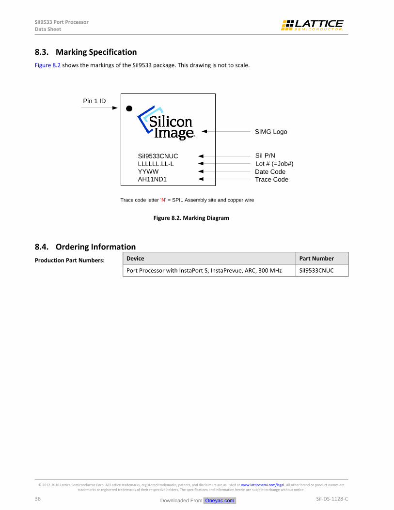
SiI9533 Port Processor Data Sheet
© 2012-2016 Lattice Semiconductor Corp. All Lattice trademarks, registered trademarks, patents, and disclaimers are as listed at www.latticesemi.com/legal. All other brand or product names are trademarks or registered trademarks of their respective holders. The specifications and information herein are subject to change without notice.
36 SiI-DS-1128-C
Marking Specification 8.3.
Figure 8.2 shows the markings of the SiI9533 package. This drawing is not to scale.
SIMG Logo
Lot # (=Job#)
Date Code
Trace Code
SiI P/NSiI9533CNUC
LLLLLL.LL-L
YYWW
AH11ND1
Pin 1 ID
Trace code letter ‘N’ = SPIL Assembly site and copper wire
Figure 8.2. Marking Diagram
Ordering Information 8.4.
Production Part Numbers: Device Part Number
Port Processor with InstaPort S, InstaPrevue, ARC, 300 MHz SiI9533CNUC
Downloaded From Oneyac.com
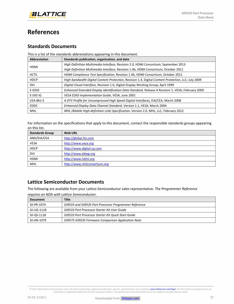
SiI9533 Port Processor Data Sheet
© 2012-2016 Lattice Semiconductor Corp. All Lattice trademarks, registered trademarks, patents, and disclaimers are as listed at www.latticesemi.com/legal. All other brand or product names are trademarks or registered trademarks of their respective holders. The specifications and information herein are subject to change without notice.
SiI-DS-1128-C 37
References
Standards Documents
This is a list of the standards abbreviations appearing in this document.
Abbreviation Standards publication, organization, and date
HDMI High Definition Multimedia Interface, Revision 2.0, HDMI Consortium; September 2013
High Definition Multimedia Interface, Revision 1.4b, HDMI Consortium; October 2011
HCTS HDMI Compliance Test Specification, Revision 1.4b, HDMI Consortium; October 2011
HDCP High-bandwidth Digital Content Protection, Revision 1.4, Digital Content Protection, LLC; July 2009
DVI Digital Visual Interface, Revision 1.0, Digital Display Working Group; April 1999
E-EDID Enhanced Extended Display Identification Data Standard, Release A Revision 1, VESA; February 2000
E-DID IG VESA EDID Implementation Guide, VESA, June 2001
CEA-861-E A DTV Profile for Uncompressed High Speed Digital Interfaces, EIA/CEA, March 2008
EDDC Enhanced Display Data Channel Standard, Version 1.1, VESA; March 2004
MHL MHL (Mobile High-definition Link) Specification, Version 2.0, MHL, LLC, February 2012
For information on the specifications that apply to this document, contact the responsible standards groups appearing on this list.
Standards Group Web URL
ANSI/EIA/CEA http://global.ihs.com
VESA http://www.vesa.org
HDCP http://www.digital-cp.com
DVI http://www.ddwg.org
HDMI http://www.hdmi.org
MHL http://www.mhlconsortium.org
Lattice Semiconductor Documents The following are available from your Lattice Semiconductor sales representative. The Programmer Reference
requires an NDA with Lattice Semiconductor.
Document Title
SiI-PR-1074 SiI9533 and SiI9535 Port Processor Programmer Reference
SiI-UG-1118 SiI9533 Port Processor Starter Kit User Guide
SiI-QS-1118 SiI9533 Port Processor Starter Kit Quick Start Guide
SiI-AN-1079 SiI9575-SiI9535 Firmware Comparison Application Note
Downloaded From Oneyac.com

SiI9533 Port Processor Data Sheet
© 2012-2016 Lattice Semiconductor Corp. All Lattice trademarks, registered trademarks, patents, and disclaimers are as listed at www.latticesemi.com/legal. All other brand or product names are trademarks or registered trademarks of their respective holders. The specifications and information herein are subject to change without notice.
38 SiI-DS-1128-C
Revision History
Revision C, March 2016
Updated to latest template.
Revision C, July 2014
Updated Audio Inputs and Outputs section.
Revision B, October 2013
Support for 4K @ 50/60 Hz added.
Revision A, September 2013
First production release.
Downloaded From Oneyac.com

7th
Floor, 111 SW 5th
Avenue
Portland, OR 97204, USA
T 503.268.8000
www.latticesemi.com
Downloaded From Oneyac.com

单击下面可查看定价,库存,交付和生命周期等信息
>>Lattice Semiconductor(莱迪思半导体)
Downloaded From Oneyac.com