sikorsky wireless test instrumentation for rotating...
TRANSCRIPT

ECE193/ME32 October 30, 2013
University of Connecticut Storrs, CT 06269 Website: http://ecesd.engr.uconn.edu/ecesd193/ E-Mail: [email protected]
Sikorsky Wireless Test Instrumentation for Rotating
Parts
ECE 193:
Olivia Bonner
David Vold
Brendon Rusch
Michael Grogan
ME 32:
Andrew Potrepka
Kyle Lindell
UCONN Faculty Advisors:
Rajeev Bansal
Robert Gao
Sikorksy Contacts:
Paul Inguanti
Chris Winslow
Dan Messner

Sikorsky Wireless Test Instrumentation 2
Table of Contents
1 Executive Summary……………………………………………………………………..………..………………3 2 Specifications…………………………………………………………………………………………………………5 3 Proposed Solution………………………………………………………………………………..……………….6 4 Electronics…………………..………………….......……………………………………………………………….7
4.1 Microcontroller………………………………………………………………………………….……7 4.2 Sensors……………………………………………………………………………………………………9 4.3 Wireless Transceiver..…………………………………………………………………………...10
5 Battery…………………………………………………………………………………………………………………11 6 Energy Harvesting……………………………………………………………………………………………..…12 7 Test Rig/Setup……………....…………………………………………………….……………………….…….13 8 Budget…………………………………………………………………………………………………………………15
8.1 Estimated Costs…………………………………………………………………………………....15 9 Timeline……………………………………………………………………………………………………………...16

Sikorsky Wireless Test Instrumentation 3
1 Executive Summary
Sikorsky helicopters rely on numerous rotating systems. These systems are crucial to the operation of the aircraft and must be monitored in order to detect system faults. Sikorsky currently utilizes a monitoring system that consists of wired sensors and slip rings. These slip rings, however, are extensively utilized at high rotational speeds and often fail due to erosion. Additionally, the wires from the sensors and slip rings add unnecessary weight to the aircraft. Consequently, Sikorsky has proposed the concept of a wireless electronic monitoring system; this system would more quickly and more efficiently monitor parameters such as temperature, noise, stress, strain and vibrations. United Technologies, Sikorsky Aircraft, has asked UCONN team EE193/ME32 to come up with a wireless solution to monitor the pitch change bearings of their S92 Helicopter. The team was allocated a budget of $2,000 to update and redesign the system created by the previous senior design team (2012-‐2013). The 2012-‐2013 UCONN student team created a wireless system in which one sensor was used. The system was powered by a battery that could handle 12 hours of operation per day and a lifetime of at least a year. In order to successfully demonstrate their system the team created a test rig to represent the tail rotor of the S-‐92 helicopter. The test rig included an accurate representation of the electronics cavity. An accelerometer was used to measure the acceleration near the tail rotor bearings. The 2012-‐2013 UCONN student team successfully created a test rig for the tail rotor of an S-‐92 helicopter and a wireless sensor system that utilized one sensor and was powered by a battery. Sikorsky has asked the current team to further the project with the addition of at least one other sensor and the utilization of energy harvesting. The team will be using a new Arduino nano microcontroller due to lack of documentation of the previous PCB and microcontroller. The team will test the following sensors as viable options for the second sensor: microphone, infrared temperature and thermometer. Wi-‐Fi will be used instead of Zig-‐Bee to transmit the signals. In order to power the

Sikorsky Wireless Test Instrumentation 4
system the team will test several methods of energy harvesting. The method that provides the most promise is magnetic energy harvesting.
Figure 1. An interior sketch of the tail rotor gearbox on the S92 helicopter

Sikorsky Wireless Test Instrumentation 5
2 Specifications
Electronics Compartment: • Size: 1.5” diameter x 5.1” long • Temperature: -‐20 to 250 degrees F
Rotating Speed of Tail Rotor Shaft • 1200 RPM
Battery Life • 1-‐year min (3 years recommended) • Run for 12 hours a day • Must survive 30 days of inactivity
Data Processing • Measure vibration • Store data temporarily • Transmit to stationary system and available at request of user • Data must travel wirelessly upwards of 40 feet
Environmental Parameters • Oil lubricated cavity • Moisture • High vibration level • Must not be visible on the exterior (hostile elements present)

Sikorsky Wireless Test Instrumentation 6
3 Proposed Solution
3.1 System Design/Circuitry
Figure 2. General system block diagram
Figure 2 illustrates the general system block diagram that the team will be utilizing. The two sensors, the accelerometer and the thermometer, are illustrated to the far left and will be communicating with the Arduino via a Serial Peripheral Interface Bus (SPI Bus) and an interrupt. The interrupt signal temporarily stops the program from collecting data, as it is only necessary to collect this information upon user command. When the device is not collecting data, it shall remain in standby mode in order to save battery life. The Arduino will be in communication with the Static Random Access Memory (SRAM) via data lines and an address. Additionally, the Arduino will be in communication with the wireless transceiver via another SPI Bus and a sleep/wake, input/output signal. The transceiver will communicate with the antenna receiver. Lastly, the Arduino will be powered via an applicable battery and an energy-‐harvesting source (to save/maintain battery life). The battery and energy harvester will need to have special circuitry to facilitate their interaction with the rest of the system. The energy harvester will need conditioning circuitry to ensure its output voltage and

Sikorsky Wireless Test Instrumentation 7
current are within limits that are useful for the demands of the system. The conditioning circuitry may include an AC to DC rectifier circuit if a vibrational energy harvesting method is utilized. Two options are possible for the interaction of the energy harvester with the battery. The system may switch between energy sources, depending on whether the energy harvester is providing the necessary power for the system, or the energy harvester may be dedicated to charging a rechargeable battery.
Figure 3. Circuit schematic utilized from the previous team (2012-2013)
The team has the above circuitry from the previous team; we plan to further analyze the system they created in order make necessary improvements. 4 Electronics
4.1 Microcontroller
We’ve decided to move the project to the open source Arduino platform. The switch has several advantages compared to the PCB used by last year’s team. Arduino will give us more flexibility in our design, as the platform offers more connectivity with a greater number of inputs, and has a wide range of compatible sensors, which are readily available. Arduino is also available at a much lower price point than similar

Sikorsky Wireless Test Instrumentation 8
custom designs. For comparison, the custom built PCB from last year cost the team around $1300, while a stock Arduino nano evaluation board costs around $30 and offers additional functionality. Lastly, Arduino is a mature platform with plenty of documentation. This is arguably the greatest advantage in the platform switch, as any problems or questions that arise during development can likely be solved using the ample sources available online. Last year’s team did not leave much information about the specifics of their design, and it would be a significant hurdle just to learn the full capabilities of their design, which may or may not meet our needs for this year. The one drawback of switching to Arduino would be an increase in power consumption. However, the additional power requirements will be mitigated by the new energy harvesting solution, which will be discussed in detail in section 6. The particular evaluation board we will use is the Arduino Nano v3.0. We believe this board offers the best combination of features while still fitting inside our size specifications. Measuring just 1.70” by 0.73”, the nano is a compact package that actually reduces the space needed from the custom PCB of last year. It however does not compromise on speed by offering the same 16mhz Atmel ATmega328 microcontroller that is used on full sized Arduino packages. It also provides 8 analog input pins and 14 digital I/O pins, which should satisfy our connectivity needs.
Arduino Nano v3.0 Specifications Table 4.1
Operating Voltage 5V
Input Voltage Range 7-12V
Digital I/O Pins 14
(6 PWM Outputs)
Analog Input Pins 8
Flash Memory 32 KB
SRAM 2 KB
Dimensions 0.70” x 1.70”

Sikorsky Wireless Test Instrumentation 9
4.2 Sensors
Accelerometer:
The accelerometer we are utilizing is the ADXL362; this component is an ultra low power 3 axis MEMS accelerometer. It consumes less than 2uA at 100Hz output data rate. This device samples the full bandwidth of the sensor at all data rates. It also features ultra-‐low power sleep states with “wake on shake” capability.
Ambient Temperature Thermometer:
The thermometer we are utilizing is the TMP36 Temperature Sensor. The thermometer can read ambient temperatures from -‐40°C to 125°C to a high degree of accuracy. The ambient temperature of the cavity is an important metric that measures whether the electronics are within safe operating temperatures.
Infrared Body Temperature Sensor:
The infrared sensor we are utilizing is the MLX90614. This sensor allows us to take measurements of the temperature of an external body. The sensor has a wide range of measurable temperatures and could theoretically be used to measure the heat given off by a bearing.
ADXL362 Table 4.2
Input Voltage Range 1.6 – 3.5V
Active Power 2uA at 100Hz
Standby Power 10 nA
Resolution 1mg/LSB
TMP36 Temperature Sensor Table 4.3
Input Voltage Range 2.7 – 5.5V
Linearity 0.5°C
Accuracy ±1°C (typical), ±2°C
Temperature Range -40°C - +125°C
Sikorsky Wireless Test Instrumentation 10
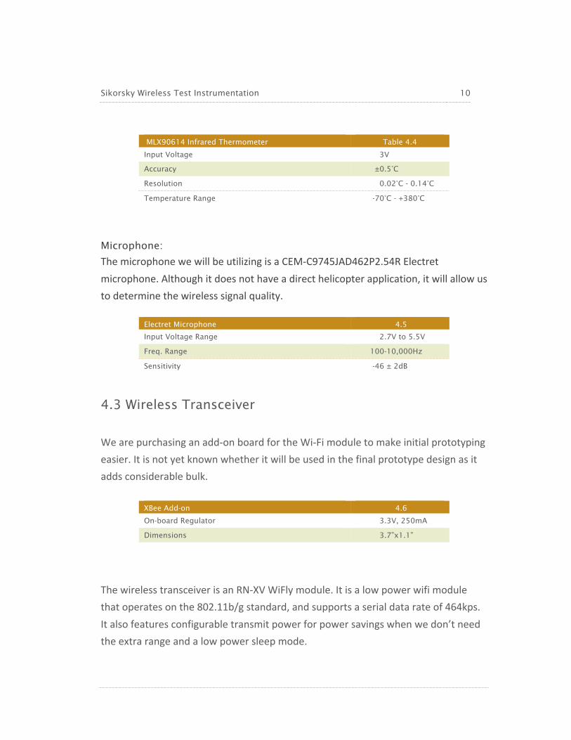
Microphone:
The microphone we will be utilizing is a CEM-‐C9745JAD462P2.54R Electret microphone. Although it does not have a direct helicopter application, it will allow us to determine the wireless signal quality.
4.3 Wireless Transceiver
We are purchasing an add-‐on board for the Wi-‐Fi module to make initial prototyping easier. It is not yet known whether it will be used in the final prototype design as it adds considerable bulk.
The wireless transceiver is an RN-‐XV WiFly module. It is a low power wifi module that operates on the 802.11b/g standard, and supports a serial data rate of 464kps. It also features configurable transmit power for power savings when we don’t need the extra range and a low power sleep mode.
MLX90614 Infrared Thermometer Table 4.4
Input Voltage 3V
Accuracy ±0.5°C
Resolution 0.02°C - 0.14°C
Temperature Range -70°C - +380°C
Electret Microphone 4.5
Input Voltage Range 2.7V to 5.5V
Freq. Range 100-10,000Hz
Sensitivity -46 ± 2dB
XBee Add-on 4.6
On-board Regulator 3.3V, 250mA
Dimensions 3.7”x1.1”

Sikorsky Wireless Test Instrumentation 11
5 Battery
The Arduino Nano and add-‐ons can be run through the Arduino’s on-‐board linear regulator with an input voltage of 7V to 12V or powered directly from a regulated 5V source, preferably using an efficient switching regulator.
Item Current Draw Table 5.1 Arduino Nano 17mA (direct 5V power with LED removed)
to 25mA (on-board regulator used, LED
intact)
Wi-Fi Module 38mA
Sensors <10mA (depending on sensors chosen)
Total 65mA-73mA
Sikorsky’s minimum requirement is that the unit must operate 12 hours per day for one year. (12 hours/day)*(365 days/year)*(73mA) = 320Ah A battery of this capacity will not fit within the electronics cavity. Thus, our design will have only a small battery coupled with an energy harvesting unit. The main functions of this battery will be to power the unit during startup and shutdown and to ensure a constant power source, as power received from an energy harvester will vary through time.
RN-XV WiFly Module 4.7
Average Active Current 38mA
Sleep Current 4uA
Input Voltage 3.3V
Serial Data Rate 464 kbps
Encryption Support yes
Transmit Power 0 -12 dB

Sikorsky Wireless Test Instrumentation 12
Several types of battery were considered:
NiCd NiMH Li-Ion Li-Poly Table 5.2 Energy Density Poor Average Good Excellent
Number of Cells
Needed for >5V
Poor (5 cells) Poor (5 cells) Good (2 cells) Good (2 cells)
Memory Yes No No No
Charging Method Simple Simple Complex Complex
Temperature Range Average Average Good Good
Impact/Shock
Resistance
Average Average Poor Poor
Overall Suitability Poor Average Good Best
For this application, lithium polymer cells are the most suitable option.
6 Energy Harvesting
The wireless test sensor system will require an energy harvesting unit in order to recharge its battery. This unit will be expected to provide power at least equal to power consumed so that no external charging of the battery is required. Energy harvesting methods investigated include piezoelectric, thermoelectric, and magnetic. Thermoelectric Piezoelectric Magnetic Power Output Insufficient Insufficient Sufficient
Size Small Workable Workable
Optimal Operating
Conditions
Large temperature
gradient
Consistent vibration
frequency within narrow
band
Fairly high rotation rate
Miscellaneous Factors -------- -------- Gravitational torque or
attachment to
stationary component
necessary
Overall Suitability for
this Application
Unusable Unusable Best
Magnetic energy harvesting is by far the most promising, but there are significant

Sikorsky Wireless Test Instrumentation 13
difficulties with installing such a unit in the rotating electronics cavity due to lack of access to any stationary parts. The only immediately apparent way to overcome this is with a unit that utilizes gravitational torque. Such a unit would consist of a generator mounted to the rotating unit and an off-‐center weight attached to its shaft. Gravity would keep the weight stationary while the rest of the unit rotates. There are limitations to such a design that would likely create problems when used in a helicopter-‐ when at extreme angles, the weight would no longer be kept stationary and could potentially begin rotating, producing significant vibrations. Thus, alternatives to gravitational torque will continue to be explored.
7 Test Rig
The previous team (from 2012-‐2013), created a rig in order to test the wireless sensing system. This team’s main goal was to test and analyze specific parameters of a rotating system through the use of sensors. What was produced was a mock-‐up of the tail rotor without the propellers. The rig has an open compartment on the end to insert the electronics capsule into and holes bored for screws which mount the capsule onto the rig once it is in the compartment. Since the size of our electronics cavity is the same dimensions as the previous year, we will be reusing the same motor and attached rig. We have ideas to modify the rig to work better with our design this year outlined below in this section. A variable-‐speed electric motor was mounted to a plate. The driveshaft of the motor was then connected to a shaft of the same diameter via a clutching mechanism. The shaft then tapers to the diameter of the helicopter’s rotor shaft and its length at this diameter is just longer than the electronics capsule, which fits into a center-‐bored cylindrical cavity, opening to the end. There are two sets of bearings: the smaller is a spherical cartridge bearing, along the taper and the larger is a roller cartridge bearing, around the midsection of the wider portion of the shaft (the portion with the same diameter as the rotor shaft). The bearings are mounted to the same plate as the motor. The use of cartridge bearings last year allowed for the team to switch

Sikorsky Wireless Test Instrumentation 14
out a working bearing with an intentionally damaged bearing to see if they could test the difference with their sensing system. The previous team did research into the bearings and found the larger bearing to fit the design specifications designated by Sikorsky. It was originally thought that these bearings would need replacement because they created a loud scraping sound, which would interfere with sensing via a microphone, but upon inspection of their physical condition, it was found that they only needed lubrication from a Teflon spray to reduce the noise. Potential Modifications to the Test Rig: The main purpose of this design project is to be able to transmit, receive and then analyze data from the sensor network, but if time is available, the plate may be mounted so the pitch of the motor and shaft can change. The data from an accelerometer in the cavity could be used to derive the pitch angle of the mount and confirm the validity of the project. Since we will be using different circuitry and electronics from last year, the electronics capsule may need to be redesigned as well to better hold everything in place.
Figure 4. Test rig created by the previous team (2012-‐2013)

Sikorsky Wireless Test Instrumentation 15
8 Budget
Sikorksy has granted team EE193/ME32 a budget of $2,000 to update and redesign the 2012-‐2013 Wireless Network System. The team has planned to utilize the mechanical components from the previous year, which should reduce the total cost to prototype and test the design.
8.1 Costs to Date and Estimated Costs
The cost of components ordered are shown below, as well as cost estimates for planned components, which have not yet been finalized.
Shopping List Table 8.1
Arduino Nano $35.00
Mini B USB Cable $4.50
XBee Add-On Board $25.00
Wifi Module $35.00
Nano Protoshield $15.00
Triple Axis Accelerometer $15.00
Infrared Thermometer $20.00
Thermometer $1.50
Electret Microphone $8.00
DC Generator (Estimated) $20.00
Power Management Circuitry (Estimated) $30.00
Battery (Estimated) $100.00
Printed Circuit Board (Estimated) $200.00
Total Price $509.00

Sikorsky Wireless Test Instrumentation 16
9 Timeline
The team has come up with an orderly timeline in order to track our progress. The timeline illustrated below displays our project goals over the course of the year.
Figure 5. EE193/ME32 Timeline for 2013-2014