silver sea - pool warehouse
TRANSCRIPT

:
: For your safety, your pool is not designed for diving and/or jumping in head first. Please do not dive. Diving may result in permanent injury or death.
INSTALLER: Once the installation of the pool is complete, it is important to give this document to the customer in person.
Installation Guide
SILVER SEAABOVE GROUND POOL

ABOVE GROUND POOL SAFETY
WARNINGFAILURE TO HEED THESE WARNINGS CAN RESULT IN PERMANENT INJURY,
PARALYSIS FROM A BROKEN NECK, ELECTROCUTION OR DROWNING.THIS POOL IS NOT DESIGNED FOR DIVING OR JUMPING!
DANGEROUS INJURY CAN RESULT, SHALLOW WATER!
Your pool contains a large quantity of water, and is deep enough to present inherent dangers to life and health unless the follow-ing safety rules are strictly observed. First-time users run the highest risk of injury. Make sure everyone understands. To insure your pool is used safely you must observe the following safety precautions:
1. NO JUMPING OR DIVINGThe top rail of your pool is not a walkway and must not be used for jumping or diving. Do not permit jumping or diving into the pool from a deck or the top rail of the pool. Diving or jumping into the pool can result in serious injury.
2. NEVER USE THE POOL ALONENever permit the pool to be used unless it is attended by at least one person other than the bather. Someone should always be available to lend assistance in an emergency.
3. NEVER LEAVE CHILDREN UNATTENDEDNever leave a child alone and unsupervised in or near the pool—not even for a second. There is no substitute for constant adult supervision.
4. NO ROUGH PLAYDo not permit “rough-playin” in and around your pool. Surfaces can become slippery and hazardous when wet.
5. LIGHT THE POOL AT NIGHTIf the pool is used after dusk, adequate lighting must be provided. Illumination in the pool area must be sufficient to clearly judge pool depth and all features in and around the pool. For light-ing recommendations, consult your local licensed electrical contractor
6. RESTRICT ACCESS TO THE POOLDo not leave chairs or other furniture beside the pool that could be used by a child to climb up into the pool. Ladders must be removed whenever the pool is unattended. A fence with a lockable gate around the pool or yard is strongly recommended and may be required by law in some jurisdictions.
7. NO ALCOHOL OR DRUGSNever drink alcoholic beverages or use any intoxicants which could hinder your judgment and reflexes.
8. KEEP YOUR POOL CLEAN AND SANITARYYour filter system will remove suspended particles from the water and the surface skimmer will remove insects, leaves and other debris from the water surface. Use the correct pool chemicals as directed to destroy harmful bacteria and prevent formation of algae. Remember, unsanitary water is a serious health hazard.
IMPORTANT NOTICE READ BEFORE INSTALLATION!The safety stickers must be installed as per following instructions. Failure to properly install warning labels will void warranty. Failure to mount these safety labels may subject you to substantial liability in case of injury. These warning are not to be re-moved under any circumstances! If they become discolored or fall off please request replacements which will be sent at no charge.
FOLLOW ALL SAFETY INSTRUCTIONSRead and follow all safety instructions packaged with pool, ladder, deck or any other accessory. Additional pool safety publications can be obtained by contacting: The Association of Pool & Spa Professionals (www.apsp.org)
9 . KEEP OFF TOP LEDGESDo not walk on top ledges. They can be slippery and they are not a walkway.
10. POOL COVER SAFETYThe cover must have a tamperproof locking retainer cable that positions the cover around the pool wall and keeps it securely in place. Never allow anyone, especially small children on the cover. Asphyxiation or drowning could result. When purchasing any pool cover, please consult a swimming pool professional.
11. ELECTRICAL HAZARDNever touch or attempt to service electrical equipment, including the filter when your body and/or the ground is wet. Electrocution or permanent injury due to high voltage (120V AC) could result. The pool should be bonded in accordance with Section 680-26 of the National Electical Code. For further assistance contact your dealer or a local licensed electrician. Do not use pool during electrical or rain storms.
12. SAFETY ROPE & POLEKeep a safety rope 1/4" by 50" with a flotation buoy with an outside diamter of 15". Have ac-cessible in a prominent area by your pool. Keep a pole not less that 16 feet (4,88m) long with a blunt or hook end available at pool side in case of emergencies.
13. POOL CHEMICALSDo not place chlorine, chlorine tablets or sticks directly into skimmer, or winterize your pool with liquid chlorine. Damage to the skimmer, pool liner and filter will result. Failure to obey this in-struction will void all component warranties. Always follow Chemical Manufacturer’s insturctions when storing, handling and dispensing pool chemicals.
14. CHECK FOR DAMAGEPeriodically check your pool and ladder components for damage and wear. Be sure all screws are in place. Replace all damaged or worn components and tighten all screws before you use the pool, deck or ladders. At first sign remove rust and touch up immediately.
15. POOL PARTSNever modify the pool or accessories, or remove or drill holes in the pool, deck or ladder com-ponents unless instructed. Your pool wall is made of thin metal, there is an inherent cut hazard with metal so use gloves during installation. Always use Original Equipment Manufactured parts for your replacement parts.
REMEMBERWATCHCHILDREN
PLACE SIGN ONLINER ABOVE WATER
LINE, OPPOSITE ENTRYTO POOL
PLACE SIGN ONWALL NEXT TO
POOL ENTRY
R.12/11
SILVER SEA ABOVE GROUND OVAL POOL INSTRUCTIONS

Installation Instructions
7” & 9” Top Rail Pool Series52” and 54” Oval Pools
573-4036
NO DIVING! Shallow water.
You can bepermanently injured.
Copyright © 1989 560-1041
WARNING

Installation Instructions
HOW TO USE THESE INSTRUCTIONS
Be sure to read these instructions completely before
beginning assembly or installation.
This installation sheet covers five sizes of oval pools. Use your pool parts list booklet and the exploded
illustrations to identify your pool parts, then read
these instructions and follow the assembly steps that
pertain to your pool assembly.
The manufacturer (HII) cannot be responsible for
damage caused by careless or improper assembly
or installation. Your warranty is void if pool assembly
and installation instructions are not followed exactly,
or if the pool design is altered in any way.
Contracted Installation
The manufacturer (HII) is not affiliated with any professional pool installers and can assume no
responsibility for installation mistakes made by the
professional installer or the homeowner. If the pool
is installed by others, please supervise and make
sure the installation complies with proper installation
techniques as shown.
Change of Design
The manufacturer (HII) expressly reserves the right
to change or modify the design and construction of
any product in due course of our manufacturing pro-
cedures, without incurring any obligation or liability
to furnish or install such changes or modifications on products previously or subsequently sold.
CAUTIONS
1. Do not attempt to install pool wall on windy days.
An unsupported pool wall can easily blow down and
may cause damage to the pool frame, pool wall, or
may cause personal injury.
2. When assembling your pool, keep parts not cur-
rently used in an area out of the way. Disassembled
parts are easily tripped over and may be damaged or
cause personal injury.
3. Do not attempt to lift heavy boxes by yourself. To
reduce the possibility of personal injury, have some-
one help you move heavy boxes (pool wall, liner,
etc.).
WARNINGS
1. Your pool must be level within 1” all around. An un-
level pool may cause excessive stress on pool frame.
This may result in pool failure which could cause
serious personal injury.
2. Your pool must be on undisturbed soil. Backfilled soil, sudden slopes within 6 feet, or water run off
may undermine or cause pool foundation to shift.
This could cause pool failure and may cause serious
personal injury.
3. To reduce the risk of severe electrical shock, al-
ways have a qualified electrician install a ground fault circuit interrupter (G.F.C.I.). Always plug pool acces-
sories into a G.F.C.I. protected receptacle.
4. Always install the Warning Decals and Warning
Sign. The decals are designed to remind you, your
friends and loved ones that your pool is to be used
for swimming and wading only. Do not allow any form
of horse play in or around the pool. Failure to follow
this warning can lead to severe personal injury. Read
the “Safety First” booklet.
5. Do not use common sand for pool cove. Common
sand can easily erode and allow pool liner to rupture
which may cause pool failure or personal injury.
6. Secure your pool when not in use. Ladders and
gates should be secured to reduce the possibility of
unauthorized entry and possible serious accidents.
7. Always repair liner leaks. Continued leakage
between pool wall and liner may cause wall damage
which eventually may result in pool wall failure. This
could result in serious personal injury.
8. To reduce the risk of possible electrical shock,
never install your pool under overhead wires.
9. Do not alter pool as pool failure may result and
cause serious bodily injury. Your warranty is void if
the pool is altered.
10. Do not bury pool or warranty is void.
11. Do not install a diving board, pool slide or any
other recreational accessories for use in diving, slid-
ing or jumping into your pool.
2

Local CodesCheck to see if building permits or utility clearances
are required. Comply with safety codes regarding
fencing and all electrical codes.
BEFORE YOU START1. Check prevailing winds. The skimmer should be
downwind to aid in removing pool surface debris.
2. Pump and filter location. Allow room to service your pool equipment.
3. Do not install your pool liner on top of anything
abrasive. Installing your liner on top of abrasives
such as concrete, asphalt, peat moss, tar paper,
gravel, or wood could puncture your liner.
4. Do not install your pool liner on top of grass or tree
roots. They may grow up through your liner.
5. Do not install your pool on soil that has recently
been treated with petroleum based chemicals.
Some soil treatment chemicals may destroy your
pool liner. Consult your pool dealer.
6. Treat the ground inside the pool area with a
non-petroleum based fungicide (available at garden
supply shops). This may help prevent liner staining
caused by fungus. Consult your pool dealer.
7. Rid pool area of burrowing pests and insects such
as gophers and termites. They can cause liner dam-
age.
8. Locate a convenient electrical outlet for filter and pump. Always have a qualified electrician install a ground fault circuit interrupter (See Warnings).
9. Check wall clearances. Be sure you have enough
room to work around your pool (18” minimum).
10. Avoid overhanging eaves. Prevent water running
off of roof and carrying debris into your pool.
11. Avoid overhanging branches. Prevent leaves and
tree branches from falling into your pool.
12. Avoid sun reflection into residence in order to prevent glare into house.
13.Keep sprinklers away from pool to avoid pool
damage.
14. Do not install pool under overhead wires (See
Warnings).
15. Be able to view children playing around pool.
Secure your pool when not in use (See Warnings).
TOOLS AND MATERIALS:1. Non-Stretch Twine 2. Garden Rake3. Nail -- 2-1/2” Long (12 Req’d)4. 18” Long Wooden Stake (12 Req’d)5. Duct Tape6. 2” x 4” Board equal in length to the pool clearance radius plus 6 inches (See “Pool Layout Dimensions”)7. Sifting Screen (to remove 1/8” pebbles)8. 2”x12”x12” Patio Blocks. (Optional) One per Verti-cal9. Binder Clips - 1 1/4” - 2” (Available at stationary stores)10. Carpenter’s Level11. Carpenter’s Saw12. Flat End Shovel13. Screwdrivers (Standard)14. 25’ Tape Measure15. Hammer16. Tamping Tool or Roller17. One or more 5/16” Nut Drivers18. Sharp Knife or Razor Knife19. Black Felt Marker20. Transit (See Step 2) 21. 7/16” Open End Wrench (2 Req’d)22. 9/16” Open End Wrench (2 Req’d)23. Hacksaw24. Drill/Bit
3
POOL LAYOUT DIMENSIONSStudy the following illustration of your pool size and familiarize yourself with the dimensions that will be used for your pool layout.
20’ X 12’
MATERIAL REQUIRED
8” x 8” x 16” concrete blocks 20’x12’ - 4 blocks 24’x12’ - 6 blocks 26’x15’ - 6 blocks 30’x15’ - 8 blocks 24’x16’ - 4 blocks 28’x16’ - 6 blocks 32’x16’ - 8 blocks 33’x18’ - 8 blocks 34’x18’ - 8 blocks 41’x21’ - 10 blocksQuick set cement 60 lb bags1/2 bag per side support
24’ X 12’

SITE PREPARATIONA level pool area is a vital part of your pool con-
struction. Avoid possible disassembly later by taking
your time and making sure the pool area is leveled
properly.
WARNING
An unleveled area my cause excessive stress on the
pool’s wall and framework, and may result in pool
failure. See Warnings. Refer to “Pool Layout Dimen-
sions” for your pool diameter.
Step 1 ...
Locate stakes A and B. Level tops with long 2” x 4”
board and carpenter’s level. Layout clearances as
shown. Remove all sod within pool area. This sod
may be saved for future landscaping needs.
4
26’ X 15’
30’ X 15’
28’ X 16’

41’ X 21’
33’ X 18’
32’ X 16’
34’ X 18’
5

Step 2 ...
Using a transit to level the pool area is preferred.
When using this method, professional assistance is
recommended.
However, a homemade leveling device can be used.
With a shovel and the constructed depth leveling
tool shown above, remove sod and level pool area.
Level to the lowest spot within pool area. Level side
areas to main pool area. Remove high points - do
not fill in low spots. Ground must always be firm. Be sure pool area is free of stones, sticks, roots and
other objects that could puncture liner. Remember:
The entire assembled pool framework must sit on flat ground within 1 inch of level at opposite sides. Spend
additional time now to avoid disassembly later.
Step 3...
Locate stakes C, D, E and F from your pool lay-
out. Attach strings between C and D, then E and F.
Locate center of two side support excavations as
shown. Other supports will be located 48” on centers
if you desire to excavate at this time.
Step 4...SIDE SUPPORT EXCAVATION
Carefully dig out side support trenches following
dimensions above. Dig out side support trenches for
the amount of side supports for your pool, refer to pool
layout. It is very important that the trench walls remain
firm and undisturbed during and after excavation. DO NOT over-excavate with the thought of back-filling later as the side supports will move when pool is filled and pool failure may result.
When digging is complete, proceed to side support.
Step 5...SIDE SUPPORT ASSEMBLY
6
Refer to Parts List and exploded view for descrip-
tions and parts reference.
Refer to parts list exploded view in your parts list
for correct hardware and parts.
Attach skid plate to bottom ground support using
(4) 1/4” bolts and nuts as shown. Tighten se-
curely using two 7/16” wrenches.
18’ WIDE POOL = 11’ LONG

Step 6...INSTALL CONCRETE BLOCKSSIDE SUPPORT ASSEMBLY CON’T
Step 7...COMPLETE BLOCK INSTALLATION
7
Slide the ground supports
into the side vertical until
the four holes are aligned
in all three pieces.
Fasten vertical to ground
supports using (4) 3/8”
bolts and nuts as shown.
Tighten securely using
two 9/16” wrenches.
Remove string line. Place concrete blocks into
the excavations as shown. NOTE: The thicker
wall side of the cement blocks must face up.
Level the blocks in both directions. Place the
assembled side supports into each trench with
skid plate resting firmly against the face of the concrete blocks. Check each ground support for
level.
Position a 24” carpenter’s level on top of the
ground supports. Adjust the side vertical as-
semblies until the ground supports are level.
When ground supports are level, the vertical will
be TILTED-IN at the top to provide a “preload”
condition so that when the pool water pressure
is against the wall, the sides will move outward
and become vertical. Without this preload, the
wall would tilt outward at the top and create a
curve in the top rails. Fill concrete blocks with concrete mix and level with top of blocks. If you have over excavated, fill any space behind the blocks with concrete. See ALTER-
NATE BLOCK SETTING above.
ALTERNATE BLOCK SETTING
ATTACH
EXTENSION
USING (4)
#10 X 1/2”
SCREWS
AS SHOWN.
Position the top ground support over the
bottom ground support and lower it to en-
close the bottom ground support.
Extension is only
used for 54” pools

8
Step 8...DIG OUT FOR PRESSURE PADS
Dig out a trench to the dimensions shown
above., grading to the ground support. Use a
large screwdriver to scribe grooves (approxi-
mately 1” deeper) down each side and center
of the trench to accomodate the pressure pads’
flanges. Remove the excess dirt accumulated from scribing.
Step 9...INSTALL PRESSURE PADS
Keep the tops of the ground supports free of
dirt. Working from left to right, assemble a set
of pressure pads to each ground support using
(6) #12x3/4” screws as shown above, refer to
your parts list as needed. Tighten screws firmly. Assemble each pressure pad set to its adjacent
set using (4) #10x1/2” screws. DO NOT OMIT
ANY SCREWS. The skid plate at the bottom of
the side support assembly must fit firmly against the concrete block and the pressure pads must
be flat on the ground with the flanges pointing down into the scribed grooves.
Step 10...INSTALL BOTTOM RAIL LOCATOR
Loosely assemble bottom rails (stamped “S”),
groove up, between verticals with bottom rail
locators. Secure bottom rail locators to side
verticals with screws. Slightly bend the bottom
rail locator tabs towards the outside of the pool.
NOTE: Be sure to use the top set of holes in the
side verticals when assembling the bottom rail
locators.
Step 11...INSTALL BOTTOM RAILS
Transition rails, note location on diagram above (*)
Begin ends of framework by installing the four rails
(*) stamped 12 for 12’ wide ovals, stamped L-15-2
for 15’ wide ovals, stamped TR-18 for 18’ wide ovals,
stamped TR for 16’ & 21’ wide ovals, place to the
outside on the end side verticals. Rails stamped “S”
go between each side vertical and the remaining rails
are for the ends. Pay close attention when installing
transition rails, these rails must be installed by the
outside edge of each side support vertical. Complete
ends by sliding bottom rails (groove up) into vertical
end caps. Confirm levelness of installation by placing level on top of bottom rails. Check around the oval
to be sure ground is flat and within 1 inch of level at opposite sides and ends of pool.

9
Step 12... INSTALL WALL
Patio Block Installation (optional but recommend-
ed): Center 12” x 12” x 2” patio blocks under vertical
end caps around ends of pool and mark their posi-
tions with a stick. Move bottom framework from ends
out of your way in sections. Turn patio blocks out
next to their marked positions. Dig soil in the marked
locations away to the depth of the patio block. Patio
blocks must sit in solid, undisturbed earth, and be
flush with level ground, and have no movement when turned back into place. Use leveling tools and/or
transit to make sure each block is level and that all
blocks are level to each other. NOTE: If you plan to
use sifted earth for pool cove, bring it into pool area
at this time. Reinstall bottom framework. Check again
for levelness, and to see that vertical end caps are
centered on patio blocks. Remove stakes C, D, E
and F. NOTE: If you will be installing a maindrain, re-
Step 13...CONNECT WALL JOINT
From this point you will need approximately 8 to 10
uninterrupted working hours. It is essential that your
pool assembly be completed with top rails and pool
filled with water or damage could occur.Remove pool wall from carton. Note “Up” arrow on
wall. Keep hands and feet from under wall during
construction. Determine starting point of wall with
respect to the desired skimmer location. The skim-
mer opening will be at the inside end of the wall coil.
Always start wall at center of a vertical end cap.
Uncoil about 6 to 10 feet of wall and insert bottom
edge into groove in bottom rails. Place stabilizer rails on top edge of pool wall, working around top of pool
as wall is inserted into bottom rails. Telescope small
diameter rail into large diameter rail about 6 inches.
Secure stabilizer rails to wall with duct tape between vertical end caps.
NOTE: Place enough sifted earth into the pool area
to cover the pressure pads and to form the cove if not
using preformed cove.
Bring the wall ends together in the center of the ver-tical end cap. If interlocking wall ends do not meet, adjust all vertical end caps in or out uniformly as required. Do not make the total adjustment with only one or two vertical end caps. Fasten wall with screws supplied in wall carton. Screw head must be on the inside of pool. When finished, go back and retighten all screws and nuts. Remove any burrs on all screw heads. Place protective vinyl strip, included in hard-ware pack, over screw heads and tape in place.
Step 14...INSTALL END VERTICALS
Refer to your Pool Parts List exploded view when assembling verticals. Attach verticals to bottom con-nectors, making sure they are straight. Refer to Fig. A or B.Carefully follow the details shown in parts list to
Carefully follow the detail in the exploded view
to attach the verticals to vertical end caps to
pool. Refer to your Pool Parts List exploded
view when assembling verticals. Attach vertical
at bottom first. Push vertical against wall, slip vertical end cap over wall and attach to verti-
cal. Make sure vertical is straight. Attach other
hardware as required in exploded view. Use all
necessary hardware.

10
Exploded view - Refer to owner’s guide for
more detailed view.
Fig. A
Side viewFig. B
EXTENSION SHOWN IS FOR 54” POOLS
ONLY. REFER TO YOUR POOLS PARTS
LIST FOR CORRECT EXPLODED VIEW
AND PARTS LOCATIONS.
IF YOUR POOLS EXPLODED VIEW IS NOT
SHOWN, PLEASE REFER TO THE PARTS LIST
INCLUDED WITH YOUR POOL.
11
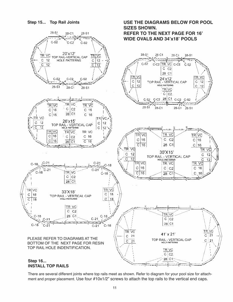
Step 15... Top Rail Joints
There are several different joints where top rails meet as shown. Refer to diagram for your pool size for attach-
ment and proper placement. Use four #10x1/2” screws to attach the top rails to the vertical end caps.
Step 16...
INSTALL TOP RAILS
USE THE DIAGRAMS BELOW FOR POOL
SIZES SHOWN.
REFER TO THE NEXT PAGE FOR 16’
WIDE OVALS AND 34’x18’ POOLS
PLEASE REFER TO DIAGRAMS AT THE
BOTTOM OF THE NEXT PAGE FOR RESIN
TOP RAIL HOLE INDENTIFICATION.

Top Rail JointsINSTALL TOP RAILS -
continued
JOINT A JOINT B JOINT C JOINT D 12’ 16’ 18’ 21’ 12’ 16’ 18’ 21’ 12’ 16’ 18’ 21’ 12’ 16’ 18’ 21’Hole 1 - Top Rail C C C C C C C C C C C C C C C C Hole 1 - End Cap C/2 C/2 C/2 C/2 C/2 C/2 C/2 C/2 S/2 C/2 S/2 C/2 12 16 18 21 Hole 2 - Top Rail 28 28 28 28 28 28 28 28 28 28 28 28 C C C C Hole 2 - End Cap C/1 C/1 C/1 C/1 C/1 C/1 C/1 C/1 S/1 C/1 S/1 C/1 12 16 18 21 Hole 3 - Top Rail C C C C C C C C C C C C C C C C Hole 3 - End Cap C/2 C/2 C/2 C/2 S/2 C/2 S/2 C/2 C/2 C/2 C/2 C/2 12 16 18 21 Hole 4 - Top Rail 28 28 28 28 28 28 28 28 28 28 28 28 C C C C Hole 4 - End Cap C/1 C/1 C/1 C/1 S/1 C/1 S/1 C/1 C/1 C/1 C/1 C/1 12 16 18 21
HOLE CHART FOR 7” & 9” TOP RAIL POOLS12’, 16’, 18’ & 21’
POOL WIDTHS
USE THE DIAGRAM AND CHART
BELOW ON THIS PAGE FOR
24’x16’, 28’x16’ and 32’x16’ POOLS
AND 34’ X 18’ POOLS.
REFER TO THE DIAGRAMS BELOW FOR TOP RAIL HOLE NUMBERS AND LETTERS FOR RESIN TOP
RAILS.
STEEL TOP RAILS ARE STAMPED WITH THE PROPER HOLE INDENTIFICATION.
12

13
Step 17...
ATTACH TOP CONNECTORS
Attach top connectors to pool. Refer to your pools ex-
ploded view for proper installation for Top connector
and skirt if applicable. Secure with screws as shown
in detail in your parts list.
Step 18...
CHECK WALL RADIUS
Important Step: At this time, fill in all excavations on outside of pool. Cover inside pressure pads and
horizontal beams with approximately 3” of damp sifted earth; tamp and blend to bottom of pool. Check
pool framework to assure level installation. Place the
level on each top rail, working gradually around pool,
to assure framework is on flat ground with opposite sides no more than 1 inch out of level. Remember:
Always remove dirt to adjust framework - never fill in! Use level to check straightness of verticals.
Using Stake A as center point, measure from stake
to pool wall to assure roundness of ends. Measure
to left wall, right wall, and to each connector at pool
end. Distance should be equal at all points. Follow
same procedure using Stake B as center point for
opposite end.
Step 19...
Important Step: The cove is a vital structural ele-
ment that prevents water pressure from forcing the
pool liner out under the bottom rail. The manufacturer
will not assume responsibility should the cove be
omitted. EARTH COVE: Use screened damp earth
to form a cove around the inside base of pool wall.
Shape and compact firmly. PRE-FORMED: Specifi-
cally designed pre-formed pool cove is available from
your dealer. Follow cove manufacturer’s instructions.
Recheck pool for roundness after installing cove.
Step 20...
Remove all Stakes. Check the pool floor (area inside pool wall) for levelness. Fill in all slight depressions
with sifted earth and tamp. Remove all stones and
sharp objects. Fill in all footprints on pool floor. Place liner on top of top rail. The loose end should over-
hang outside of pool by about 12 inches. Hold end
and unfold liner down middle of pool as you would a
carpet. Do not place liner side seam over skimmer
or return fitting opening. The center seam of the liner must be positioned at the center line of the pool.
Step 21...
Work in both directions from the point where the liner
is overhanging. Unfold liner, drape over the top rail
and down the sides approximately 24 inches. The
liner should be barely above the pool floor in the center ONLY. Remember that the center seam of the
liner must be positioned at the center line of the pool.
The bottom edge seam of the liner should be inside
the pool about 12 inches from the top rails. Correct
bunching or pleating conditions in the liner wall. In-
spect liner for open seams. If found, return to dealer
for prompt replacement of liner.
22
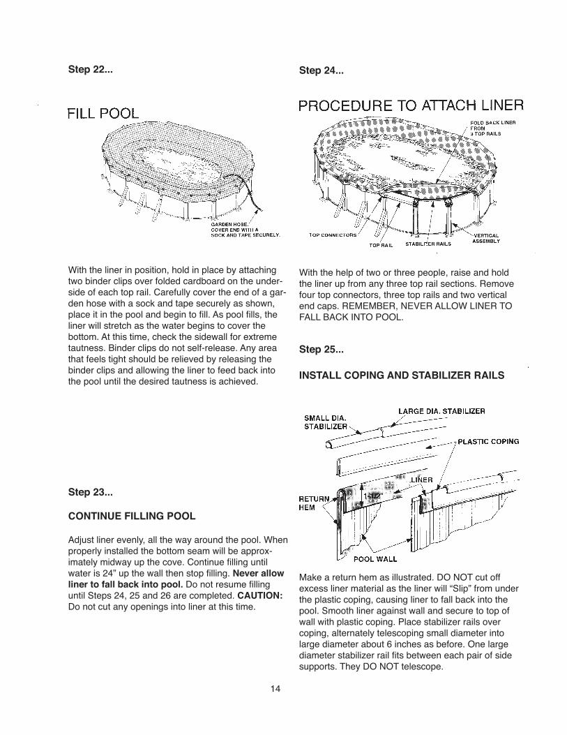
Step 22...
With the liner in position, hold in place by attaching
two binder clips over folded cardboard on the under-
side of each top rail. Carefully cover the end of a gar-
den hose with a sock and tape securely as shown,
place it in the pool and begin to fill. As pool fills, the liner will stretch as the water begins to cover the
bottom. At this time, check the sidewall for extreme
tautness. Binder clips do not self-release. Any area
that feels tight should be relieved by releasing the
binder clips and allowing the liner to feed back into
the pool until the desired tautness is achieved.
Step 23...
CONTINUE FILLING POOL
Adjust liner evenly, all the way around the pool. When
properly installed the bottom seam will be approx-
imately midway up the cove. Continue filling until water is 24” up the wall then stop filling. Never allow liner to fall back into pool. Do not resume filling until Steps 24, 25 and 26 are completed. CAUTION:
Do not cut any openings into liner at this time.
Step 24...
With the help of two or three people, raise and hold
the liner up from any three top rail sections. Remove
four top connectors, three top rails and two vertical
end caps. REMEMBER, NEVER ALLOW LINER TO
FALL BACK INTO POOL.
Step 25...
INSTALL COPING AND STABILIZER RAILS
Make a return hem as illustrated. DO NOT cut off
excess liner material as the liner will “Slip” from under
the plastic coping, causing liner to fall back into the
pool. Smooth liner against wall and secure to top of
wall with plastic coping. Place stabilizer rails over coping, alternately telescoping small diameter into
large diameter about 6 inches as before. One large
diameter stabilizer rail fits between each pair of side supports. They DO NOT telescope.
14

NOTE: At the skimmer and return openings only,
the return hem must be cut away between the steel
side wall and the liner side wall. (This will insure that
there is only onle thickness of liner material covering
the skimmer and return openings to affect a positive
gasket seal). DO NOT CUT the liner sidewall at any
other location. Replace all parts removed in Step 25.
Repeat same steps for entire pool perimeter, working
just three top rail sections at a time. DO NOT allow
liner to fall back into pool.
Step 26...
With pool completely assembled, install skimmer,
filter, etc. using instructions provided with units. Consult with your dealer for the proper chemicals and
water treatment recommended.
Cleaning
Pool parts are easily cleaned with a mild liquid soap
and a soft cloth. Do not use abrasive cleaning pads,
or cleaners containing abrasives as they may scratch
or dull the surface appearance.
SAFETY LITERATURE
Now that you have installed your new pool, you can
look forward to many years of fun and enjoyment.
However, your pool is also a big responsibility. For
this reason, we have provided you with an assort-
ment of safety literature. Please take the time to
read and understand all the safety literature
provided.
You have also been given an assortment of signs
and decals. Refer to your “Safety First” booklet for
detailed instructions of where and how to apply them.
Remember, warnings only help if you put them up.
Please help us protect the good health and safety of
your family and friends! Read the “Safety First” book-
let through completely and follow the directions in it.
If any of your safety literature, signs, or decals
become lost or damaged, you can get more free by
contacting HII Customer Service Department:
HII
315 N. Sebastian Street
West Helena, AR 72390
(870) 572-3466
IMPORTANT: Above-ground pools are designed
for swimming and wading only. Diving or Jumping is
product of mis-use. DO NOT DIVE OR JUMP! Use
only an above-ground swimming pool ladder to enter
or exit your pool. Do not use slides, diving boards,
or any other platform or object which can be used
for improper pool entry! It is your responsibility
to secure your pool against unauthorized, un-
supervised, or unintentional entry. Remember,
pool mis-use can result in severe injury and/or other dangers to life and health. Always obey and
enforce all safety rules.
HII • 315 N. Sebastian St. • West Helena, AR 72390
DB 0218-254 Made in the United States of America Copyright © 2018
PREVENTDROWNING
Watch children at all times.
You can be permanently injured.
Shallow water.
WARNING
Do not remove or cover. RESCUE:
NO DIVING!