sim808 evbkit userguide v1 - simcom.ee kit_user guide_v1.00.pdf · connectoron sim900evbkit,plugin...
TRANSCRIPT

SIM808_EVBKIT_User Guide_V1.00

Smart Machine Smart Decision
SIM808_EVBKIT_User Guide_V1.00 2015-07-272
Document Title: SIM808_EVBKIT_User Guide
Version: 1.00
Date: 2015-07-27
Status: Release
Document Control ID: SIM808_EVBKIT_User Guide_V1.00
General NotesSIMCom offers this information as a service to its customers, to support application andengineering efforts that use the products designed by SIMCom. The information provided isbased upon requirements specifically provided to SIMCom by the customers. SIMCom hasnot undertaken any independent search for additional relevant information, including anyinformation that may be in the customer’s possession. Furthermore, system validation of thisproduct designed by SIMCom within a larger electronic system remains the responsibility ofthe customer or the customer’s system integrator. All specifications supplied herein aresubject to change.
CopyrightThis document contains proprietary technical information which is the property of SIMComLimited., copying of this document and giving it to others and the using or communication ofthe contents thereof, are forbidden without express authority. Offenders are liable to thepayment of damages. All rights reserved in the event of grant of a patent or the registration ofa utility model or design. All specification supplied herein are subject to change withoutnotice at any time.
Copyright © Shanghai SIMCom Wireless Solutions Ltd. 2013
Smart Machine Smart Decision
SIM808_EVBKIT_User Guide_V1.00 2015-07-273
Contents
1 EVBKIT Accessory..............................................................................6
2 TE Introduce........................................................................................ 8
3 EVBKIT Introduce............................................................................10
3.1 Power Interface................................................................................................................. 113.2 Audio Interface..................................................................................................................123.3 SIM Card Interface............................................................................................................133.4 Serial Port Interface.......................................................................................................... 133.5 LED Indicator....................................................................................................................143.6 Test Interface.....................................................................................................................15
3.6.1. J103........................................................................................................................... 153.6.2. J201........................................................................................................................... 163.6.3. J104........................................................................................................................... 17
4 Illustration:.........................................................................................18
4.1 Turn on Module:................................................................................................................184.2 Turn off Module................................................................................................................ 184.3 Registering Network and Making a Call.......................................................................... 184.4 Software Upgrade............................................................................................................. 23

Smart Machine Smart Decision
SIM808_EVBKIT_User Guide_V1.00 2015-07-274
Figure IndexFIGURE 1: EVBKIT ACCESSORY......................................................................................................6FIGURE 2: EVBKIT AND ACCESSORY............................................................................................ 7FIGURE 3: TE TOP VIEW.....................................................................................................................8FIGURE 4: TE BOTTOM VIEW...........................................................................................................9FIGURE 5: EVBKIT TOP VIEW.........................................................................................................10FIGURE 6: EVBKIT BOTTOM VIEW...............................................................................................10FIGURE 7: POWER INTERFACE......................................................................................................11FIGURE 8: AUDIO INTERFACE....................................................................................................... 12FIGURE 9: SIM CARD INTERFACE................................................................................................ 13FIGURE 10: SERIAL PORT INTERFACE........................................................................................13FIGURE 11: LED INDICATOR...........................................................................................................14FIGURE 12: TEST INTERFACE OVERVIEW..................................................................................15FIGURE 13: J103 INTERFACE.......................................................................................................... 15FIGURE 14: J201 INTERFACE.......................................................................................................... 16FIGURE 15: J104 INTERFACE.......................................................................................................... 17
Smart Machine Smart Decision
SIM808_EVBKIT_User Guide_V1.00 2015-07-275
Version History:
Data Version Description of change Author
2015-07-27 1.00 Xiuyu.zhang
SCOPE
This document presents the usage of EVBKIT. This document can apply to SIM8008-EVBKIT.

Smart Machine Smart Decision
SIM808_EVBKIT_User Guide_V1.00 2015-07-276
1 EVBKIT Accessory
Figure 1: EVBKIT accessory
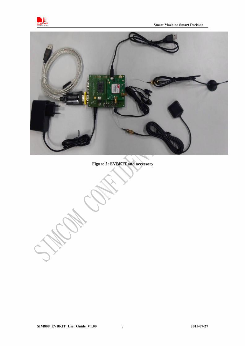
A: USB-to-RS232 cableB: 5V DC adapterC: GPS antennaD: GSM antennaE: Mini gender changerF: SIM900 EVBKITG: SIM808-TEH: Earphone (2.5mm)I: USB data cableJ: RF Cable RFC-SMA
Smart Machine Smart Decision
SIM808_EVBKIT_User Guide_V1.00 2015-07-277
Figure 2: EVBKIT and accessory

Smart Machine Smart Decision
SIM808_EVBKIT_User Guide_V1.00 2015-07-278
2 TE Introduce
Figure 3: TE top view
A: Test connector of GSM antenna
B: Test connector of Bluetooth antenna (default)B1: SMA connector of Bluetooth antennaC: Test connector of GPS antenna (default)C1: SMA connector of GPS antennaD: SIM808 moduleE: Two jumpersF: Micro-USB interface (for firmware upgrading and debugging)G: Test point of VBAT and GND

Smart Machine Smart Decision
SIM808_EVBKIT_User Guide_V1.00 2015-07-279
Figure 4: TE bottom view
H: SD card interfaceI: Te-Module interfaceNote:
1. When use the charging function, connect the jumper to the left if charged by the USB; Connect to the right
if use the DC adapter.
2. Do not push in the SD card if the function is not used, as the pushing will change some signals to the SD
card interface. For more details, please refer to the HD spec.
Smart Machine Smart Decision
SIM808_EVBKIT_User Guide_V1.00 2015-07-2710
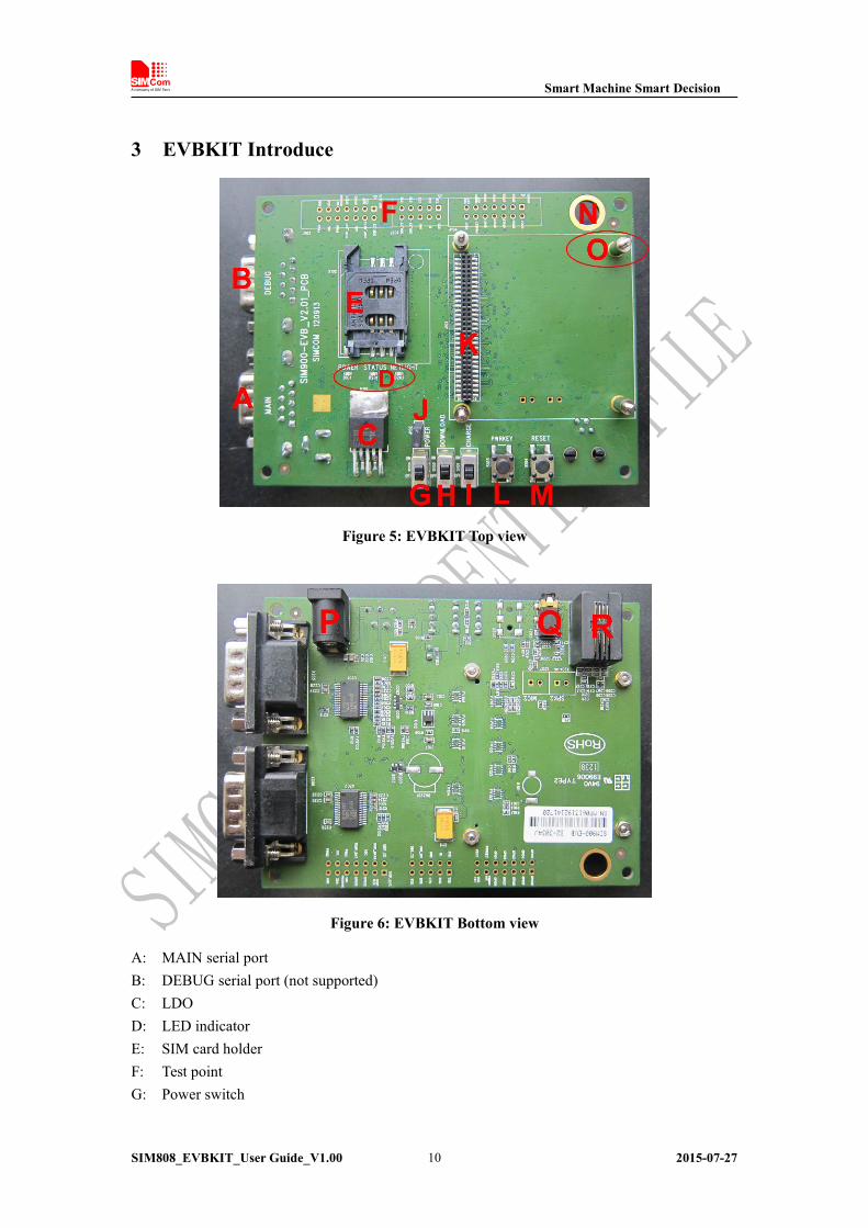
3 EVBKIT Introduce
Figure 5: EVBKIT Top view
Figure 6: EVBKIT Bottom view
A: MAIN serial portB: DEBUG serial port (not supported)C: LDOD: LED indicatorE: SIM card holderF: Test pointG: Power switch
Smart Machine Smart Decision
SIM808_EVBKIT_User Guide_V1.00 2015-07-2711
H: Download switchI: Charge switchJ: VBAT jumperK: Module-TE interfaceL: Power keyM: Reset keyN: GND PADO: Module fix holeP: DC jackQ: 2.5mm earphone jackR: Headphones jack
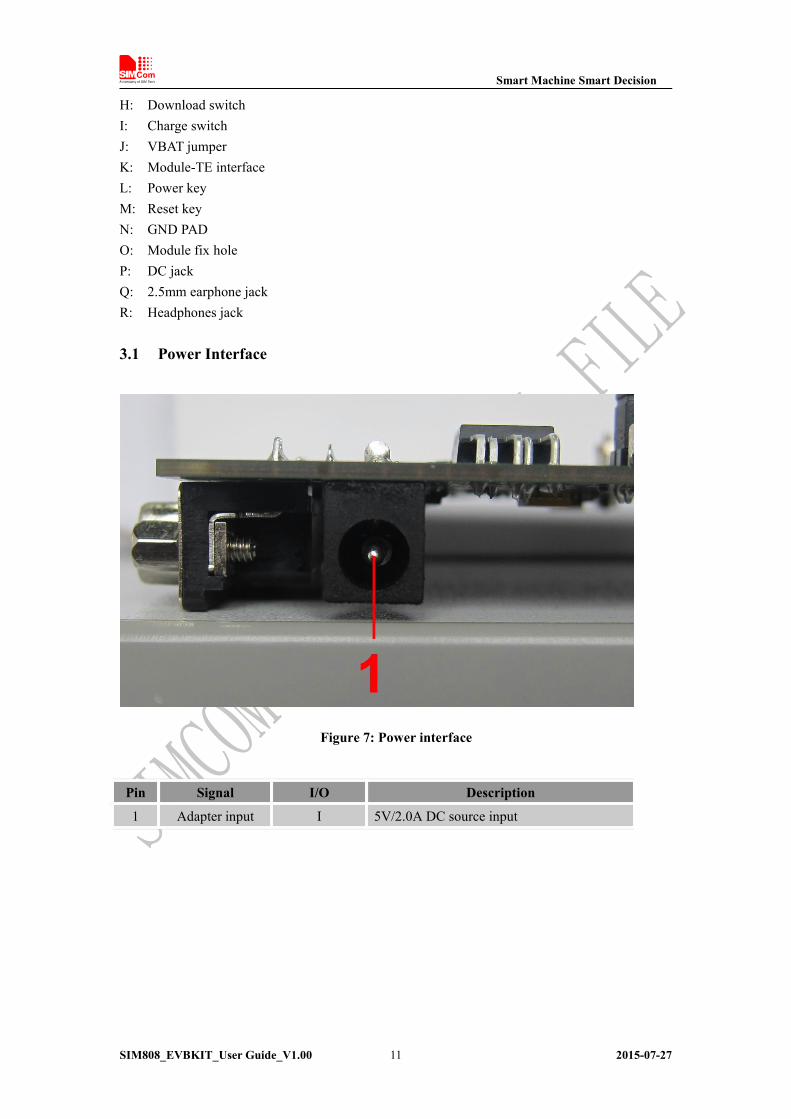
3.1 Power Interface
Figure 7: Power interface
Pin Signal I/O Description
1 Adapter input I 5V/2.0A DC source input

Smart Machine Smart Decision
SIM808_EVBKIT_User Guide_V1.00 2015-07-2712
3.2 Audio Interface
Figure 8: Audio interface
Headset interface:
Pin Signal I/O Description
1 MIC1P I Positive microphone input
2 SPK1P O Positive receiver output
3 MIC1N I Negative microphone input
4 SPK1N O Negative receiver output
Earphone interface:
Pin Signal Input/Output Description
5 MIC1P&SPK1P I/O Audio input/output
Smart Machine Smart Decision
SIM808_EVBKIT_User Guide_V1.00 2015-07-2713
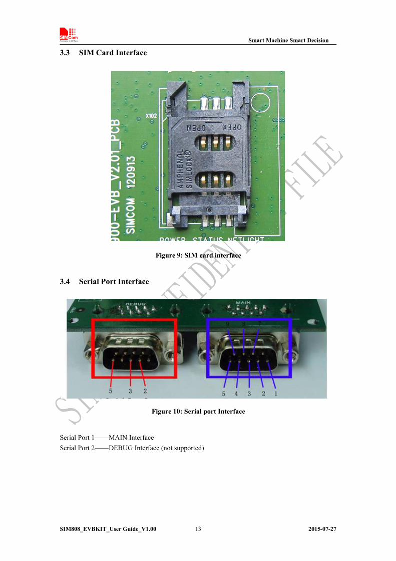
3.3 SIM Card Interface
Figure 9: SIM card interface
3.4 Serial Port Interface
Figure 10: Serial port Interface
Serial Port 1——MAIN InterfaceSerial Port 2——DEBUG Interface (not supported)

Smart Machine Smart Decision
SIM808_EVBKIT_User Guide_V1.00 2015-07-2714
Main Interface:
Pin Signal I/O Description
1 DCD O Data carrier detection
2 TXD O Transmit data
3 RXD I Receive data
4 DTR I Data Terminal Ready
5 GND GND
7 RTS I Request to Send
8 CTS O Clear to Send
9 RI O Ring Indicator
3.5 LED Indicator
Figure 11: LED Indicator
Working state of LED as list:
Name Description STATUS
Q1 Power ON/OFF indicatorBright: EVBKIT Power ON;Extinct: EVBKIT Power OFF
Q2 Module status indicator Bright: Module runs normallyExtinct: System is powered down
Q3 GSM_NET status indicator Blinking at a certain frequency according various GSMnet status
Smart Machine Smart Decision
SIM808_EVBKIT_User Guide_V1.00 2015-07-2715
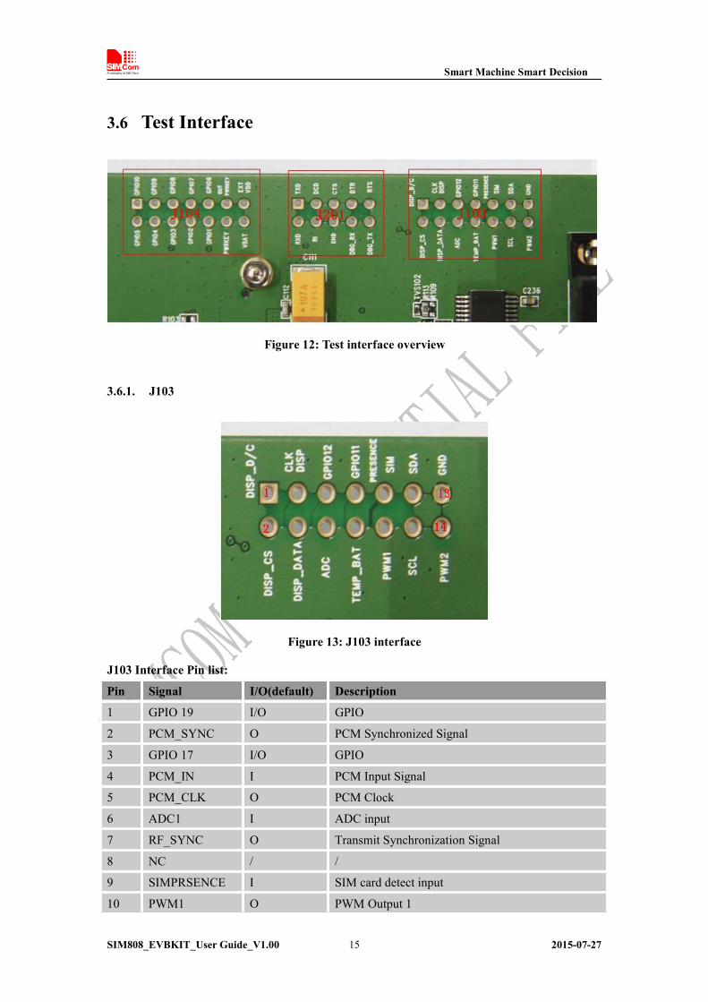
3.6 Test Interface
Figure 12: Test interface overview
3.6.1. J103
Figure 13: J103 interface
J103 Interface Pin list:
Pin Signal I/O(default) Description
1 GPIO 19 I/O GPIO
2 PCM_SYNC O PCM Synchronized Signal
3 GPIO 17 I/O GPIO
4 PCM_IN I PCM Input Signal
5 PCM_CLK O PCM Clock
6 ADC1 I ADC input
7 RF_SYNC O Transmit Synchronization Signal
8 NC / /
9 SIMPRSENCE I SIM card detect input
10 PWM1 O PWM Output 1

Smart Machine Smart Decision
SIM808_EVBKIT_User Guide_V1.00 2015-07-2716
11 SCL I/O I2C BUS CLOCK
12 PWM2 O PWM Output 2
13 SDA I/O I2C BUS DATA
14 GND / GND
Note: if customers use SIM808-TE, test point actual function please refers to the table”J103Interface Pin List”
3.6.2. J201
Figure 14: J201 Interface
J201 Interface Pin List:
Pin Signal I/O Description
1 TXD O Transmit data
2 RXD I Receive data
3 DCD O Data carrier detection
4 RI O Ring Indicator
5 CTS O Clear to Send
6 GND / GND
7 DTR I Data Terminal Ready
8 NC / /
9 RTS I Request to Send
10 NC / /

Smart Machine Smart Decision
SIM808_EVBKIT_User Guide_V1.00 2015-07-2717
3.6.3. J104
Figure 15: J104 Interface
J104 Interface Pin List:
Pin Signal I/O Description
1 GPIO/KBC0 I/O GPIO, keypad column
2 GPIO/KBR0 I/O GPIO, keypad row
3 GPIO/KBC1 I/O GPIO, keypad column
4 GPIO/KBR1 I/O GPIO, keypad row
5 GPIO/KBC2 I/O GPIO, keypad column
6 GPIO/KBR2 I/O GPIO, keypad row
7 GPIO/KBC3 I/O GPIO, keypad column
8 GPIO/KBR3 I/O GPIO, keypad row
9 NC / /
10 NC / /
11 PWRKEY I POWER KEY
12 VBAT POWER POWER
13 PCM_OUT O PCM Output Signal
14 VDD_EXT POWER VEXT
Smart Machine Smart Decision
SIM808_EVBKIT_User Guide_V1.00 2015-07-2718
4 Illustration:
4.1 Turn on Module:
(1) Keep S101, S102 and S105 at ‘OFF’ state, connect the Module-TE to the 60pinsconnector on SIM900 EVBKIT, plug in 5V DC adapter, switch S105 to ‘ON’ state;.
(2) Press the S103 (PWRKEY) for more than 1 second and then release, the module willpower on.
The LED D101 will be on if the DC adapter is connected and the LED D201 will be on whenthe module has been powered on. And after a while, the LED D202 will flash at a certainfrequency. Through the state of LED (D202), you can judge registering status of the module.For detailed description, please refer to the module HD spec.
Note: You should equip four sets of screws for better grounding to achieve a better performance.
4.2 Turn off Module
Press the S103 (PWRKEY) for about 2 seconds, the module will be turned off.After the module is turned off, the LED D201 and D202 will be off.
4.3 Registering Network and Making a Call
(1) Connect the antenna to the Module-TE, insert SIM card and earphone.(2) Connect the serial port cable to the MAIN serial port; Open the Hyper Terminal (AT
command windows) on your computer.
First, check the serial port number:My computer (right click) →Manage → Device Manager → Ports (COM&LPT)

Smart Machine Smart Decision
SIM808_EVBKIT_User Guide_V1.00 2015-07-2719
Second, use the Hyper Terminal to call the module as following:
a) Open the HyperTerminalSTART→ All Programs → Accessory →Communication → HyperTerminal.

Smart Machine Smart Decision
SIM808_EVBKIT_User Guide_V1.00 2015-07-2720
b) Configure the serial port number

Smart Machine Smart Decision
SIM808_EVBKIT_User Guide_V1.00 2015-07-2721
c) Set the baud rate and flow control
User can set the baud rate from 1200bps to 115200bps, and the flow control set to ‘None’
(3) Act on the step of running which mentioned above, power on the module, typing the ATcommand in the HyperTerminal, and then the module will execute its correspondingfunction.
a) Connect the module

Smart Machine Smart Decision
SIM808_EVBKIT_User Guide_V1.00 2015-07-2722
Click the ‘call’ icon.b) Typing the AT command. When module is powered on with autobauding
enabled, user must firstly send ‘AT’ to synchronize the baud rate. The defaultsetting of the module is autobauding.
c) Use AT command to make a call.
Smart Machine Smart Decision
SIM808_EVBKIT_User Guide_V1.00 2015-07-2723
4.4 Software Upgrade
Customer could upgrade module’s firmware through USB or UART interface.
1) Upgrade module’s firmware through USB port
Keep S101, S102 and S105 at ‘OFF’ state, connect the Module-TE to the 60pinsconnector on SIM900 EVBKIT;
Select the jumper S101 which is on TE board to the left, which means connect theVCHG to VBUS.
Open the upgrade tool, select the “USB download without battery” mode, and thenclick ”Start All” button;
At last, insert the USB, the upgrade tool will automatically enter the upgrade process;Note : Must be properly installed MTK chip driver.
2) Upgrade module’s firmware through UART port
Keep S101, S102 and S105 at ‘OFF’ state, connect the Module-TE to the 60pinsconnector on SIM900 EVBKIT;
Plug in 5V DC adapter to EVBKIT; Connect EVBKIT MAIN UART port and the PC USB port through the USB-to-RS232
cable; Open the upgrade tool, click ‘Start All’ button after configuration options Switch S105 and S102 to ‘On’ state, the upgrade tool will automatically enter the
upgrade process.
Smart Machine Smart Decision
SIM808_EVBKIT_User Guide_V1.00 2015-07-2724
Contact us:Shanghai SIMCom Wireless Solutions Co.,Ltd.Address: Building A, SIM Technology Building, No. 633, Jinzhong Road, Shanghai,P. R. China 200335Tel: +86 21 3252 3300Fax: +86 21 3252 2030URL: www.sim.com/wm