simatic box pc 620 - usedplcs.co.ukusedplcs.co.uk/manuals/siemens/pc/boxpc620/box_pc_e.pdf ·...
TRANSCRIPT
Preface, Table of Contents
Product Overview 1Commissioning the SIMATIC BoxPC 620 2
Welcome to the SIMATIC Box PC 620 3Setting-up and Operatingthe SIMATIC Box PC 620 4
SIMATIC Box PC 620 Expansions 5
Configuring the SIMATIC Box PC 620 6
Error Diagnosis 7
Hardware Information 8
Appendix
Guidelines for ESDA
Glossary, Index
Edition 08/2001C79000-G7076-C639-04
SIMATIC Box PC 620
Manual
SIMATIC

Safety information
This manual contains information which you must observe for your personal safety and toprevent material damage. The information is denoted by a warning triangle and is representedas follows, depending on the degree of endangerment:
!Warning
means that death, serious injury or considerable material damage can result, if the appropriatesafety precautions are not taken.
!Caution
means that slight injury or material damage can result, if the respective safety precautions arenot taken.
Note
is an important piece of information about the product, the handling of the product or therespective part of the documentation which should be noted in particular.
Qualified personnel
Only qualified personnel may make changes to the device on the basis of the technicaldescription. Qualified personnel are persons, who have the authorisation to install, ground andlabel, devices, systems and circuits in accordance with the standards of safety engineering.
As directed use
Please note the following:
!Warning
The device may only be used for the application cases specified in the catalogue and thetechnical description and may only be used in combination with extraneous equipment andcomponents recommended or approved by Siemens.
Appropriate transport, appropriate storage, installation and assembly as well as carefuloperation and maintenance are required to ensure that the product operates perfectly andsafely.
Trademarks
SIMATIC, SIMATIC HMI and SIMATIC NET are registered trademarks of Siemens AG.
The remaining marks in this publication may be trademarks, whose use by third parties for theirown purposes could violate the rights of the owner.
.
Exclusion of liabilityCopyright Siemens AG 2000 All rights reserved
The transmission and reproduction of this documentation and theexploitation and communication of its contents are not allowed,unless expressly granted. Contraventions are liable tocompensation for damage. All rights reserved, especially in the caseof the granting of a patent or registration by GM.
Siemens AGBereich Automatisierungs- und AntriebstechnikGeschäftsgebiet Industrie-AutomatisierungssystemePostfach 4848, D- 90327 Nürnberg
Siemens AG 2000Subject to technical change.
Siemens Aktiengesellschaft C79000-G7076-C639
iiiSIMATIC Box PC 620 ManualC79000-G7076-C639-04
Preface
What this Manual is About
This manual contains all the information you need for working with the SIMATICBox PC 620 programming device. You can use it to
unpack the programming device and power it up.
familiarize yourself with the functions and settings of the various components(display, keyboard, programming facilities etc.).
connect the programming device up to other units of equipment (programmablecontrollers, other programming devices).
expand your system, provided you comply with the necessary conditions.
analyze and eliminate simple faults.
Who is the Manual Intended For?
The following persons require the manual:
Users commissioning the programming device themselves or working with it(editing, programming or debugging).
System administrators operating the programming device in a network.
Service and maintenance personnel using the SIMATIC Box PC 620 for systemexpansion purposes or error/fault analysis.
Scope of the manual
The content of this manual describes the as delivered condition of theSIMATIC Box PC 620 for January 2000. You will find the currently valid technicaldata for your device in the operating manual which is supplied with the device.
Approvals
You will find the approvals, certificates and certifications valid for your device inChapter 1 of the operating manual.
Product name SIMATIC Box PC 620
The abbreviation PC is also used in this publication for the product name SIMATIC Box PC 620.
Preface
ivSIMATIC Box PC 620 Manual
C79000-G7076-C639-04
Information Classification
The following publication is enclosed with your SIMATIC Box PC 620 which enables you to carry out initial installation and commissioning:
The operating manual of the SIMATIC Box PC 620 with the applicable technical data and software.
Please refer to the associated manuals for further directions for handling the soft-ware.
Pointers through the Manual
The manual contains in the Chapters 1 to 4 the most important instructions forstarting up and using the programming device of the SIMATIC BOX PC 620. Chapters 5 to 8 are reference sections you will require only in special cases.
Installation
Before you use the SIMATIC BOX PC 620 for the first time, read Chapter 2 aboutthe possibilities for assembly and installation on the SIMATIC Box PC 620’s components and functionality.
Start up
Chapter 4 describes the basics steps necessary for starting up theSIMATIC BOX PC 620.
Expansion
Chapter 4 describes how to expand your SIMATIC BOX PC 620 (e.g. installation ofmemory expansions). Please observe the safety notes.
Configuration
Modifications to the system hardware may make it necessary for you to adapt theoriginal hardware configuration. Chapter 6 tells how to proceed in this case.
Error/Fault Dignostics
Chapter 7 will tell you how to deal with simple faults that you can diagnose and, insome cases, eliminate yourself.
Reference Data
Chapter 8 contains hardware addresses, interrupt assignments and information onconnecting cables.
ESD instructions
The instructions for handling electrostatic sensitive devices are of particular impor-tance for service and maintenance engineers who install expansions or carry outerror analysis with the SIMATIC Box PC 620.
Glossary
The glossary explains important terms.

Preface
vSIMATIC Box PC 620 ManualC79000-G7076-C639-04
Alphbetical Index
The index will enable you to quickly find passages in the text pertaining toimportant keywords.
Further support
Please contact your Siemens contact person at a maintenance and repair locationor the SIMATIC hotline iif you have any questions about using theSIMATIC Box PC 620 which are not answered in the manual. You will find theaddresses in the operating manual.

Preface
viSIMATIC Box PC 620 Manual
C79000-G7076-C639-04
viiSIMATIC Box PC 620 ManualC79000-G7076-C639-04
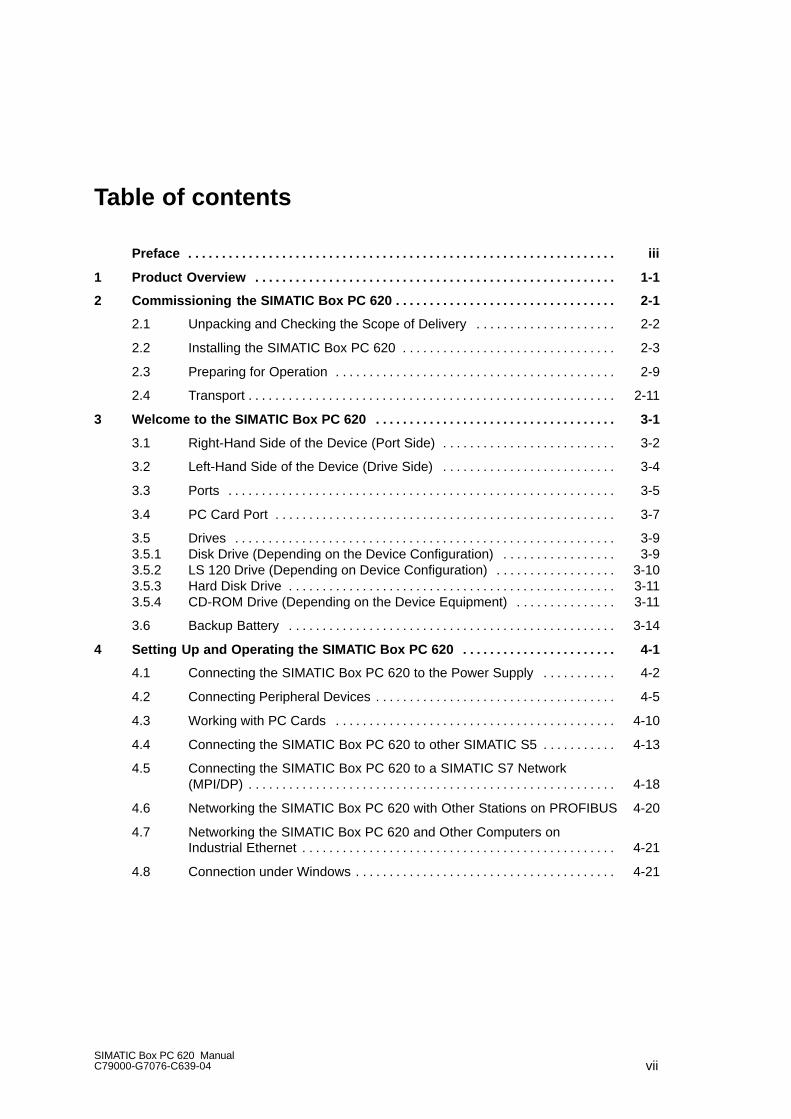
Table of contents
Preface iii. . . . . . . . . . . . . . . . . . . . . . . . . . . . . . . . . . . . . . . . . . . . . . . . . . . . . . . . . . . . . . . .
1 Product Overview 1-1. . . . . . . . . . . . . . . . . . . . . . . . . . . . . . . . . . . . . . . . . . . . . . . . . . . . . .
2 Commissioning the SIMATIC Box PC 620 2-1. . . . . . . . . . . . . . . . . . . . . . . . . . . . . . . . .
2.1 Unpacking and Checking the Scope of Delivery 2-2. . . . . . . . . . . . . . . . . . . . .
2.2 Installing the SIMATIC Box PC 620 2-3. . . . . . . . . . . . . . . . . . . . . . . . . . . . . . . .
2.3 Preparing for Operation 2-9. . . . . . . . . . . . . . . . . . . . . . . . . . . . . . . . . . . . . . . . . .
2.4 Transport 2-11. . . . . . . . . . . . . . . . . . . . . . . . . . . . . . . . . . . . . . . . . . . . . . . . . . . . . . .
3 Welcome to the SIMATIC Box PC 620 3-1. . . . . . . . . . . . . . . . . . . . . . . . . . . . . . . . . . . .
3.1 Right-Hand Side of the Device (Port Side) 3-2. . . . . . . . . . . . . . . . . . . . . . . . . .
3.2 Left-Hand Side of the Device (Drive Side) 3-4. . . . . . . . . . . . . . . . . . . . . . . . . .
3.3 Ports 3-5. . . . . . . . . . . . . . . . . . . . . . . . . . . . . . . . . . . . . . . . . . . . . . . . . . . . . . . . . .
3.4 PC Card Port 3-7. . . . . . . . . . . . . . . . . . . . . . . . . . . . . . . . . . . . . . . . . . . . . . . . . . .
3.5 Drives 3-9. . . . . . . . . . . . . . . . . . . . . . . . . . . . . . . . . . . . . . . . . . . . . . . . . . . . . . . . . 3.5.1 Disk Drive (Depending on the Device Configuration) 3-9. . . . . . . . . . . . . . . . . 3.5.2 LS 120 Drive (Depending on Device Configuration) 3-10. . . . . . . . . . . . . . . . . . 3.5.3 Hard Disk Drive 3-11. . . . . . . . . . . . . . . . . . . . . . . . . . . . . . . . . . . . . . . . . . . . . . . . . 3.5.4 CD-ROM Drive (Depending on the Device Equipment) 3-11. . . . . . . . . . . . . . .
3.6 Backup Battery 3-14. . . . . . . . . . . . . . . . . . . . . . . . . . . . . . . . . . . . . . . . . . . . . . . . .
4 Setting Up and Operating the SIMATIC Box PC 620 4-1. . . . . . . . . . . . . . . . . . . . . . .
4.1 Connecting the SIMATIC Box PC 620 to the Power Supply 4-2. . . . . . . . . . .
4.2 Connecting Peripheral Devices 4-5. . . . . . . . . . . . . . . . . . . . . . . . . . . . . . . . . . . .
4.3 Working with PC Cards 4-10. . . . . . . . . . . . . . . . . . . . . . . . . . . . . . . . . . . . . . . . . .
4.4 Connecting the SIMATIC Box PC 620 to other SIMATIC S5 4-13. . . . . . . . . . .
4.5 Connecting the SIMATIC Box PC 620 to a SIMATIC S7 Network (MPI/DP) 4-18. . . . . . . . . . . . . . . . . . . . . . . . . . . . . . . . . . . . . . . . . . . . . . . . . . . . . . .
4.6 Networking the SIMATIC Box PC 620 with Other Stations on PROFIBUS 4-20
4.7 Networking the SIMATIC Box PC 620 and Other Computers on Industrial Ethernet 4-21. . . . . . . . . . . . . . . . . . . . . . . . . . . . . . . . . . . . . . . . . . . . . . .
4.8 Connection under Windows 4-21. . . . . . . . . . . . . . . . . . . . . . . . . . . . . . . . . . . . . . .
Table of contents
viiiSIMATIC Box PC 620 Manual
C79000-G7076-C639-04
5 SIMATIC Box PC 620 Expansions 5-1. . . . . . . . . . . . . . . . . . . . . . . . . . . . . . . . . . . . . . . .
5.1 Opening the Unit 5-2. . . . . . . . . . . . . . . . . . . . . . . . . . . . . . . . . . . . . . . . . . . . . . . . 5.1.1 Prerequisites 5-2. . . . . . . . . . . . . . . . . . . . . . . . . . . . . . . . . . . . . . . . . . . . . . . . . . . 5.1.2 Opening the SIMATIC BOX PC 620 5-4. . . . . . . . . . . . . . . . . . . . . . . . . . . . . . . . 5.1.3 Components Visible After Opening the Unit 5-5. . . . . . . . . . . . . . . . . . . . . . . . . 5.1.4 Block Diagram of the Motherboard 5-6. . . . . . . . . . . . . . . . . . . . . . . . . . . . . . . . . 5.1.5 The Motherboard 5-7. . . . . . . . . . . . . . . . . . . . . . . . . . . . . . . . . . . . . . . . . . . . . . . .
5.2 Installing Memory Expansion Submodules 5-9. . . . . . . . . . . . . . . . . . . . . . . . . .
5.3 Replacing the Backup Battery 5-11. . . . . . . . . . . . . . . . . . . . . . . . . . . . . . . . . . . . .
5.4 Installation of Expansion Cards 5-13. . . . . . . . . . . . . . . . . . . . . . . . . . . . . . . . . . . . 5.4.1 Removal and Installation of the Device for Holding Down the modules 5-15. . 5.4.2 Removal and Installation of an Expansion Card 5-17. . . . . . . . . . . . . . . . . . . . . .
5.5 Removal and Installation of Drives 5-18. . . . . . . . . . . . . . . . . . . . . . . . . . . . . . . . . 5.5.1 Removal and Installation of the Hard Disk Drive 5-18. . . . . . . . . . . . . . . . . . . . . 5.5.2 Removal and Installation of a CD-ROM Drive 5-20. . . . . . . . . . . . . . . . . . . . . . . 5.5.3 Removal and Installation of the Floppy Drive 5-21. . . . . . . . . . . . . . . . . . . . . . . . 5.5.4 Removal and Installation of the LS 120 Drive 5-22. . . . . . . . . . . . . . . . . . . . . . . .
5.6 Removal and Installation of the Power Supply Unit 5-23. . . . . . . . . . . . . . . . . . .
5.7 Removal and Installation of the Bus Board 5-24. . . . . . . . . . . . . . . . . . . . . . . . . . 5.7.1 Removal and Installation of the Motherboard 5-25. . . . . . . . . . . . . . . . . . . . . . . .
5.8 Removal and Installation of the Fan 5-26. . . . . . . . . . . . . . . . . . . . . . . . . . . . . . . .
5.9 Processor Upgrade 5-27. . . . . . . . . . . . . . . . . . . . . . . . . . . . . . . . . . . . . . . . . . . . . .
5.10 Switch Settings / Jumpers 5-28. . . . . . . . . . . . . . . . . . . . . . . . . . . . . . . . . . . . . . . .
5.11 Reset Button 5-29. . . . . . . . . . . . . . . . . . . . . . . . . . . . . . . . . . . . . . . . . . . . . . . . . . .
6 Configuring the SIMATIC Box PC 620 6-1. . . . . . . . . . . . . . . . . . . . . . . . . . . . . . . . . . . .
6.1 Changing the Device Configuration with SETUP 6-2. . . . . . . . . . . . . . . . . . . . . 6.1.1 The Main Menu 6-5. . . . . . . . . . . . . . . . . . . . . . . . . . . . . . . . . . . . . . . . . . . . . . . . . 6.1.2 The Advanced Menu 6-15. . . . . . . . . . . . . . . . . . . . . . . . . . . . . . . . . . . . . . . . . . . . . 6.1.3 The Security Menu 6-23. . . . . . . . . . . . . . . . . . . . . . . . . . . . . . . . . . . . . . . . . . . . . . 6.1.4 The Power Menu 6-25. . . . . . . . . . . . . . . . . . . . . . . . . . . . . . . . . . . . . . . . . . . . . . . . 6.1.5 The Boot Sequence Menu 6-27. . . . . . . . . . . . . . . . . . . . . . . . . . . . . . . . . . . . . . . . 6.1.6 The Version Menu 6-29. . . . . . . . . . . . . . . . . . . . . . . . . . . . . . . . . . . . . . . . . . . . . . . 6.1.7 The Exit Menu 6-30. . . . . . . . . . . . . . . . . . . . . . . . . . . . . . . . . . . . . . . . . . . . . . . . . . 6.1.8 Default Setup Settings 6-31. . . . . . . . . . . . . . . . . . . . . . . . . . . . . . . . . . . . . . . . . . .
6.2 Configuring the PC Card 6-34. . . . . . . . . . . . . . . . . . . . . . . . . . . . . . . . . . . . . . . . .
7 Error Diagnosis 7-1. . . . . . . . . . . . . . . . . . . . . . . . . . . . . . . . . . . . . . . . . . . . . . . . . . . . . . . .
7.1 Diagnosing Errors 7-2. . . . . . . . . . . . . . . . . . . . . . . . . . . . . . . . . . . . . . . . . . . . . . .
7.2 Self-Test of the SIMATIC Box PC 620 before Booting 7-3. . . . . . . . . . . . . . . .

Table of contents
ixSIMATIC Box PC 620 ManualC79000-G7076-C639-04
8 Hardware Information 8-1. . . . . . . . . . . . . . . . . . . . . . . . . . . . . . . . . . . . . . . . . . . . . . . . . . .
8.1 Current Requirement of the Components (Maximum Values) 8-2. . . . . . . . . .
8.2 Overview of the Components and Ports 8-3. . . . . . . . . . . . . . . . . . . . . . . . . . . .
8.3 Hardware Address Table 8-4. . . . . . . . . . . . . . . . . . . . . . . . . . . . . . . . . . . . . . . . .
8.4 Interrupt Assignments 8-8. . . . . . . . . . . . . . . . . . . . . . . . . . . . . . . . . . . . . . . . . . . .
8.5 Video Modes 8-10. . . . . . . . . . . . . . . . . . . . . . . . . . . . . . . . . . . . . . . . . . . . . . . . . . .
8.6 Monitoring functions 8-11. . . . . . . . . . . . . . . . . . . . . . . . . . . . . . . . . . . . . . . . . . . . . 8.6.1 Overview 8-11. . . . . . . . . . . . . . . . . . . . . . . . . . . . . . . . . . . . . . . . . . . . . . . . . . . . . . . 8.6.2 Signals on the Front Interface 8-11. . . . . . . . . . . . . . . . . . . . . . . . . . . . . . . . . . . . . 8.6.3 Temperature Monitoring/Indication 8-12. . . . . . . . . . . . . . . . . . . . . . . . . . . . . . . . . 8.6.4 Watchdog (WD) 8-13. . . . . . . . . . . . . . . . . . . . . . . . . . . . . . . . . . . . . . . . . . . . . . . . .
8.7 Ports 8-14. . . . . . . . . . . . . . . . . . . . . . . . . . . . . . . . . . . . . . . . . . . . . . . . . . . . . . . . . . 8.7.1 External Ports 8-14. . . . . . . . . . . . . . . . . . . . . . . . . . . . . . . . . . . . . . . . . . . . . . . . . . 8.7.2 Assignment of the Front Ports on the Motherboard 8-25. . . . . . . . . . . . . . . . . . . 8.7.3 Assignment of the Internal Ports on the Motherboard 8-30. . . . . . . . . . . . . . . . .
8.8 Bus Board 8-38. . . . . . . . . . . . . . . . . . . . . . . . . . . . . . . . . . . . . . . . . . . . . . . . . . . . . . 8.8.1 Design and Mode of Operation 8-38. . . . . . . . . . . . . . . . . . . . . . . . . . . . . . . . . . . . 8.8.2 Interface to the Motherboard 8-39. . . . . . . . . . . . . . . . . . . . . . . . . . . . . . . . . . . . . .
8.9 CD-ROM Drive 8-44. . . . . . . . . . . . . . . . . . . . . . . . . . . . . . . . . . . . . . . . . . . . . . . . . .
8.10 Power Supply (AC) 8-46. . . . . . . . . . . . . . . . . . . . . . . . . . . . . . . . . . . . . . . . . . . . . .
8.11 Power Supply (DC) 8-47. . . . . . . . . . . . . . . . . . . . . . . . . . . . . . . . . . . . . . . . . . . . . .
8.12 Connecting Cables 8-48. . . . . . . . . . . . . . . . . . . . . . . . . . . . . . . . . . . . . . . . . . . . . .
A Guidelines for handling electrostatic sensitive devices (ESD) A-1. . . . . . . . . . . .
A.1 What does ESD mean? A-2. . . . . . . . . . . . . . . . . . . . . . . . . . . . . . . . . . . . . . . . . .
A.2 Electrostatic charging A-3. . . . . . . . . . . . . . . . . . . . . . . . . . . . . . . . . . . . . . . . . . . .
A.3 Basic protective measures against discharge of static electricity A-4. . . . . . .
Glossary Glossar-1. . . . . . . . . . . . . . . . . . . . . . . . . . . . . . . . . . . . . . . . . . . . . . . . . . . . . . . . . .
Index Index-1. . . . . . . . . . . . . . . . . . . . . . . . . . . . . . . . . . . . . . . . . . . . . . . . . . . . . . . . . . . . .

Table of contents
xSIMATIC Box PC 620 Manual
C79000-G7076-C639-04
1-1SIMATIC Box PC 620 ManualC79000-G7076-C639-04
Product Overview
Overview
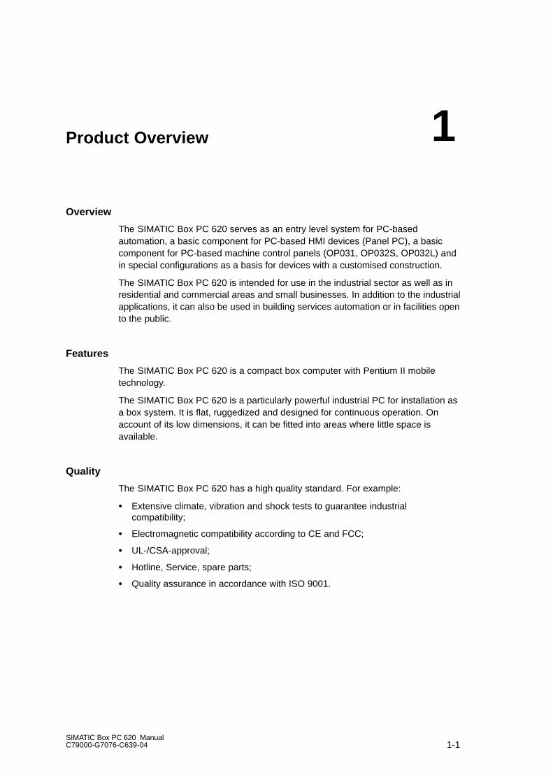
The SIMATIC Box PC 620 serves as an entry level system for PC-based automation, a basic component for PC-based HMI devices (Panel PC), a basiccomponent for PC-based machine control panels (OP031, OP032S, OP032L) andin special configurations as a basis for devices with a customised construction.
The SIMATIC Box PC 620 is intended for use in the industrial sector as well as inresidential and commercial areas and small businesses. In addition to the industrialapplications, it can also be used in building services automation or in facilities opento the public.
Features
The SIMATIC Box PC 620 is a compact box computer with Pentium II mobiletechnology.
The SIMATIC Box PC 620 is a particularly powerful industrial PC for installation asa box system. It is flat, ruggedized and designed for continuous operation. On account of its low dimensions, it can be fitted into areas where little space is available.
Quality
The SIMATIC Box PC 620 has a high quality standard. For example:
Extensive climate, vibration and shock tests to guarantee industrial compatibility;
Electromagnetic compatibility according to CE and FCC;
UL-/CSA-approval;
Hotline, Service, spare parts;
Quality assurance in accordance with ISO 9001.
1
Product Overview
1-2SIMATIC Box PC 620 Manual
C79000-G7076-C639-04
Range of Application
The SIMATIC Box PC 620 is a basic device for high performance automation solutions. It meets the highest requirements through:
compliance with the requirements for a fire enclosure to EN60950/UL508(device with AC power supply), i.e. it may be used without an additional fireenclosure,
extremely compact dimensions,
suitability for continuous 24 hour operation,
serviceability in a wide ambient temperature range,
high robustness,
a design which is extremely easy to service and maintain.
Fitting Option
The SIMATIC Box PC 620 can be installed in all the usual positions.
There are anchorage points on both of the long sides for securing the box. Mounting brackets can be screwed on to these anchorage points.
Functions
The SIMATIC Box PC 620 is equipped with software that allows it to be useduniversally. The following software packages are available:
Operating system Windows NT Server or Workstation;
or
Operating system Windows 98
or
Operating system Windows 2000
Due to its hardware, the SIMATIC Box PC 620 additionally allows the use of:
SIMATIC supplementary software
Software from the entire world of automation
Software from the PC world
Further Areas of Application:
The SIMATIC Box PC 620 can also be used in other areas of automation (SIMATIC HMI; TELEPERM; SINUMERIK; SIROTEC etc.).
Product Overview
1-3SIMATIC Box PC 620 ManualC79000-G7076-C639-04
Advantages of the SIMATIC Box PC 620
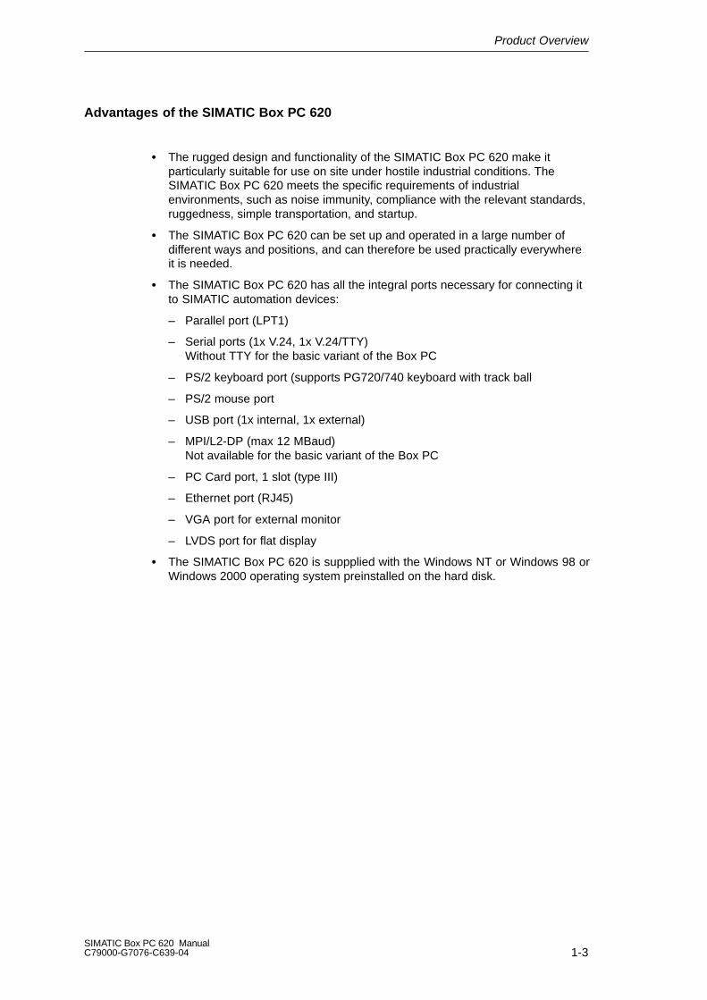
The rugged design and functionality of the SIMATIC Box PC 620 make it particularly suitable for use on site under hostile industrial conditions. The SIMATIC Box PC 620 meets the specific requirements of industrial environments, such as noise immunity, compliance with the relevant standards,ruggedness, simple transportation, and startup.
The SIMATIC Box PC 620 can be set up and operated in a large number of different ways and positions, and can therefore be used practically everywhereit is needed.
The SIMATIC Box PC 620 has all the integral ports necessary for connecting itto SIMATIC automation devices:
– Parallel port (LPT1)
– Serial ports (1x V.24, 1x V.24/TTY)Without TTY for the basic variant of the Box PC
– PS/2 keyboard port (supports PG720/740 keyboard with track ball
– PS/2 mouse port
– USB port (1x internal, 1x external)
– MPI/L2-DP (max 12 MBaud)Not available for the basic variant of the Box PC
– PC Card port, 1 slot (type III)
– Ethernet port (RJ45)
– VGA port for external monitor
– LVDS port for flat display
The SIMATIC Box PC 620 is suppplied with the Windows NT or Windows 98 orWindows 2000 operating system preinstalled on the hard disk.

Product Overview
1-4SIMATIC Box PC 620 Manual
C79000-G7076-C639-04
2-1SIMATIC Box PC 620 ManualC79000-G7076-C639-04
Commissioning the SIMATIC Box PC 620
Overview of Chapter
In chapter you will find on page
2.1 Unpacking and Checking the Scope of Delivery 2-2
2.2 Installing the SIMATIC Box PC 620 2-3
2.3 Preparing for Operation 2-9
2.4 Transport 2-11
2

Commissioning the SIMATIC Box PC 620
2-2SIMATIC Box PC 620 Manual
C79000-G7076-C639-04
2.1 Unpacking and Checking the Scope of Delivery
Unpacking the SIMATIC Box PC 620
Unpack your SIMATIC Box PC 620 programming device as follows:
1. Remove the packing.
2. Do not throw the original packing away. Keep it in case you have to transportthe unit again sometime in the future.
3. Please keep the documentation in a safe place. It is required during the initialstart up (see Section 5.2) and is part of the device.
4. Check the packing and its contents for any shipping or transport damage.
5. Check with the packing list to make sure no components are missing. Alsocheck the accessory parts, which you can order separately.
6. Please inform your local dealer of any shipping or transport damages and ofoutstanding items indicated on the packing list.
Recording the Serial Number
Enter the serial no. of your SIMATIC Box PC 620 in the table. It is on the nameplate above the floppy disk drive.
If a programming device is stolen and subsequently submitted for repair, the repaircenter will be able to identify it by the serial number (F-No).
F-No.
MLFB-No.

Commissioning the SIMATIC Box PC 620
2-3SIMATIC Box PC 620 ManualC79000-G7076-C639-04
2.2 Installing the SIMATIC Box PC 620
The SIMATIC Box PC 620 can be operated in all the usual fitting positions. It isparticularly suitable for fitting in consoles, switch boards and control panels.
The SIMATIC Box PC 620 with AC power supply meets the requirements for afire enclosure to EN60950. it can therefore be fitted without an additional fireenclosure.
The SIMATIC Box PC 620 with DC power supply is an open device (right deviceside); therefore the mounting must meet the requirements of a fire enclosure.
Please note the following points when installing the PC:
Avoid extreme ambient conditions as far as possible. Protect your PC fromdust, moisture, and heat.
Keep the PC out of direct sunlight.
Mount the PC as safely as possible to prevent any danger (for example, byfalling over).
The clearance around the housing must be at least 100 mm at the front andrear, so that the PC is sufficiently ventilated.
Make certain that the ventilation slots for the housing are not covered.
Observe the permissible fitting positions without fail when installing thesystems.
!Warnung
If the systems are installed in a non-permissible fitting position, the approvalspursuant to UL 1950, UL 508 and EN60950 are no longer valid!
Commissioning the SIMATIC Box PC 620
2-4SIMATIC Box PC 620 Manual
C79000-G7076-C639-04
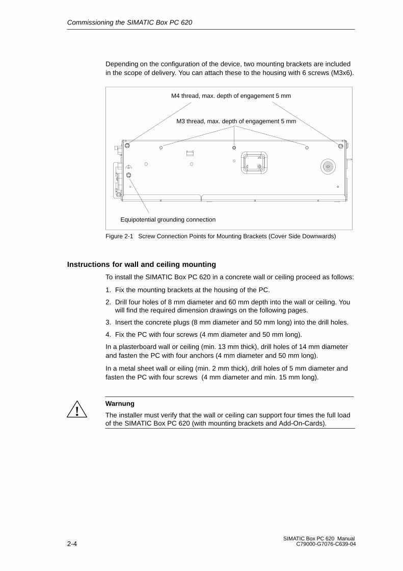
Depending on the configuration of the device, two mounting brackets are includedin the scope of delivery. You can attach these to the housing with 6 screws (M3x6).
M4 thread, max. depth of engagement 5 mm
M3 thread, max. depth of engagement 5 mm
Equipotential grounding connection
Figure 2-1 Screw Connection Points for Mounting Brackets (Cover Side Downwards)
Instructions for wall and ceiling mounting
To install the SIMATIC Box PC 620 in a concrete wall or ceiling proceed as follows:
1. Fix the mounting brackets at the housing of the PC.
2. Drill four holes of 8 mm diameter and 60 mm depth into the wall or ceiling. Youwill find the required dimension drawings on the following pages.
3. Insert the concrete plugs (8 mm diameter and 50 mm long) into the drill holes.
4. Fix the PC with four screws (4 mm diameter and 50 mm long).
In a plasterboard wall or ceiling (min. 13 mm thick), drill holes of 14 mm diameterand fasten the PC with four anchors (4 mm diameter and 50 mm long).
In a metal sheet wall or eiling (min. 2 mm thick), drill holes of 5 mm diameter andfasten the PC with four screws (4 mm diameter and min. 15 mm long).
!Warnung
The installer must verify that the wall or ceiling can support four times the full loadof the SIMATIC Box PC 620 (with mounting brackets and Add-On-Cards).
Commissioning the SIMATIC Box PC 620
2-5SIMATIC Box PC 620 ManualC79000-G7076-C639-04
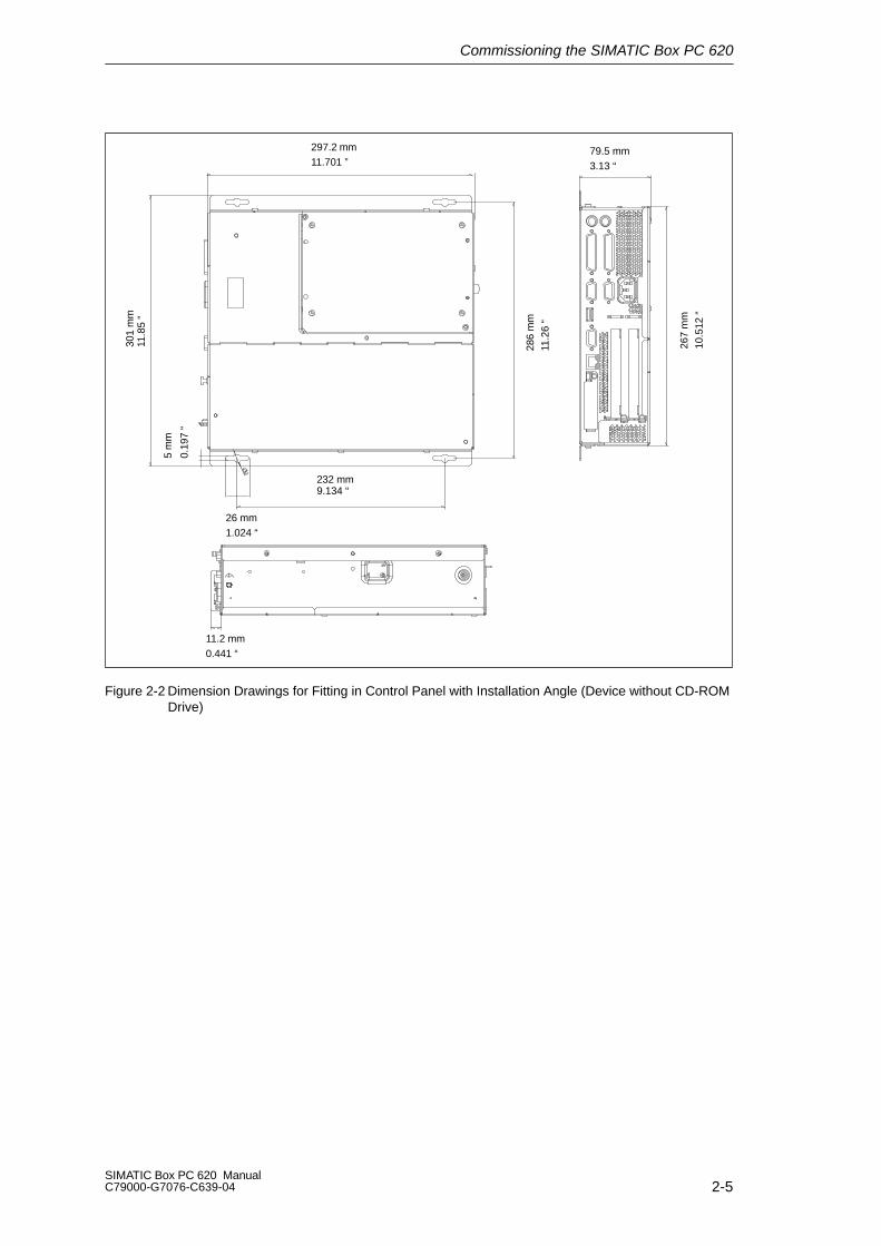
297.2 mm11.701 ”
79.5 mm3.13 “
301
mm
11.8
5 “
286
mm
11.2
6 “
267
mm
10.5
12 “
232 mm9.134 “
11.2 mm0.441 “
5 m
m
0.19
7 “
26 mm1.024 “
Figure 2-2 Dimension Drawings for Fitting in Control Panel with Installation Angle (Device without CD-ROMDrive)
Commissioning the SIMATIC Box PC 620
2-6SIMATIC Box PC 620 Manual
C79000-G7076-C639-04
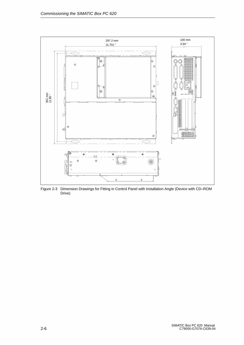
297.2 mm11.701 ”
100 mm3.94 “
301
mm
11.8
5 “
Figure 2-3 Dimension Drawings for Fitting in Control Panel with Installation Angle (Device with CD–ROMDrive)
Commissioning the SIMATIC Box PC 620
2-7SIMATIC Box PC 620 ManualC79000-G7076-C639-04
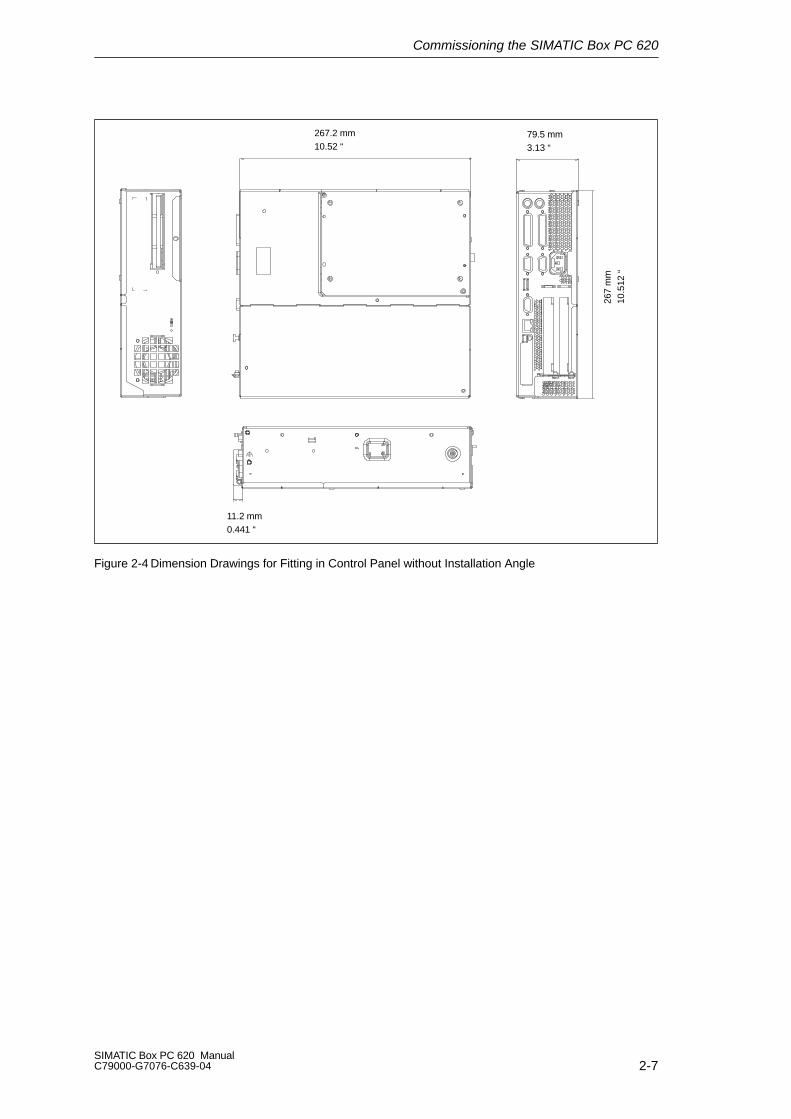
11.2 mm0.441 “
267.2 mm10.52 “
79.5 mm3.13 “
267
mm
10.5
12 “
Figure 2-4 Dimension Drawings for Fitting in Control Panel without Installation Angle
Commissioning the SIMATIC Box PC 620
2-8SIMATIC Box PC 620 Manual
C79000-G7076-C639-04
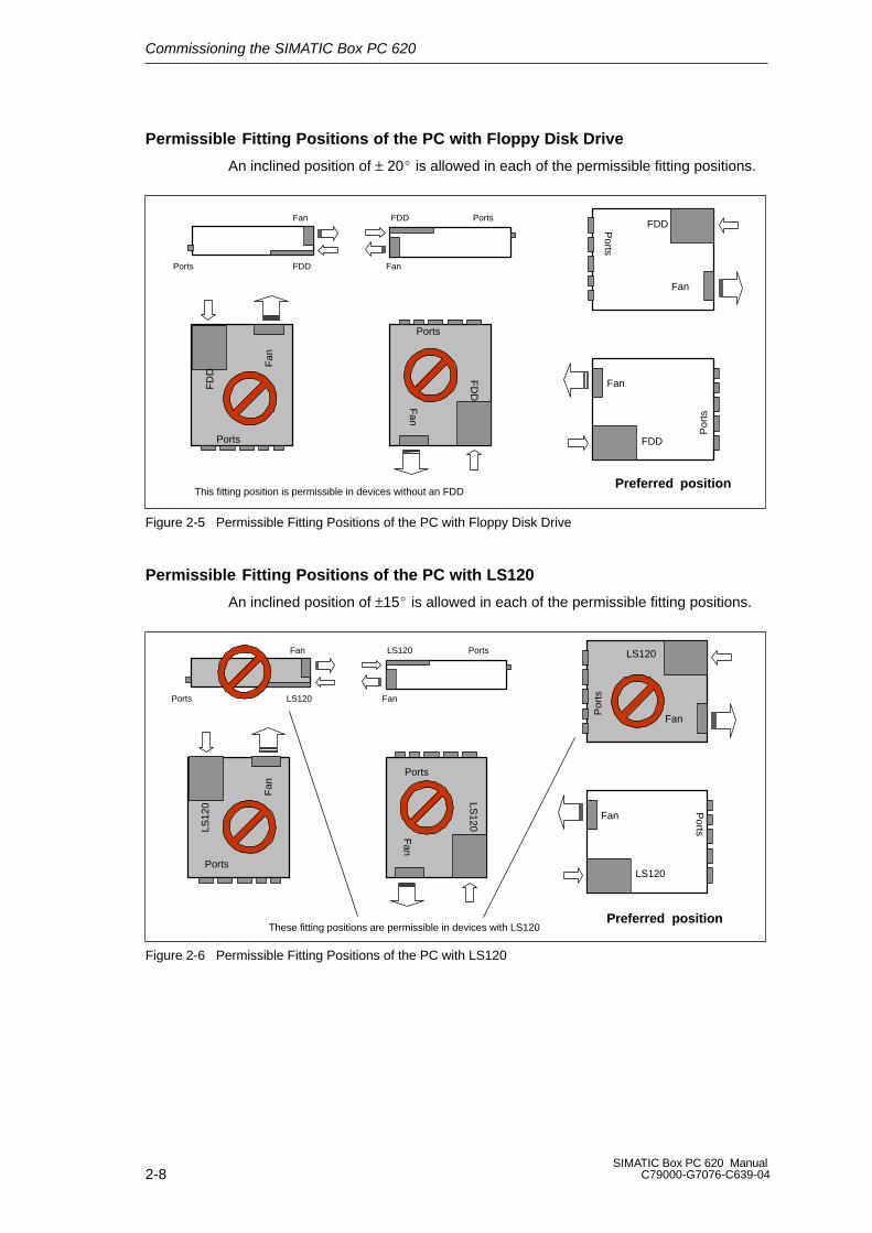
Permissible Fitting Positions of the PC with Floppy Disk Drive
An inclined position of ± 20 is allowed in each of the permissible fitting positions.
FDDPorts
Fan
Ports
FD
D
Ports
Fan
FDD
Por
ts
Fan
Ports
Fan
FDD
Ports
Fan
FDDF
an
FD
D
This fitting position is permissible in devices without an FDDPreferred position
Figure 2-5 Permissible Fitting Positions of the PC with Floppy Disk Drive
Permissible Fitting Positions of the PC with LS120
An inclined position of ±15 is allowed in each of the permissible fitting positions.
LS120
Fan
Ports
Fan
LS120
Ports
Fan
LS120
Por
ts
Fan
Ports
Fan
LS120
Ports
Fan
LS120
PortsLS
120
These fitting positions are permissible in devices with LS120
Preferred position
Figure 2-6 Permissible Fitting Positions of the PC with LS120
Commissioning the SIMATIC Box PC 620
2-9SIMATIC Box PC 620 ManualC79000-G7076-C639-04
2.3 Preparing for Operation
Connection to the Power Supply Unit
Note
The SIMATIC Box PC 620 is equipped with a safety-tested mains cable and mayonly be connected to a grounded grounding outlet.
Make sure that the socket on the device or the grounding outlet of the buildinginstallation is easily accessible and as near as possible to the device.
The SIMATIC Box PC 620 has no mains switch. The mains plug must be pulledout for complete mains separation. This point must be easily accessible.
If the PC is installed in a cabinet, there must be a central mains disconnector.
The standard power supply unit of the SIMATIC Box PC 620 is designed for115/230V systems.
The power supply unit has automatic mains voltage changeover. It is not necessary to adjust the voltage span.
Equipotential Measures
Low-impedance ground connections ensure that faults arising from external powersupply cables, signalling cables or cables to peripheral units are diverted.
Therefore connect the equipotential grounding connection on the system housingto the central earth terminal of the cabinet or the unit, into which the computer isfitted, in such a way that it has low impedance (large surface area, large contacts).The minimum cross section should not be less than 5 mm2.
The connection is on the side of the device and is identified by the symbol:

Commissioning the SIMATIC Box PC 620
2-10SIMATIC Box PC 620 Manual
C79000-G7076-C639-04
Connecting and Switching on the SIMATIC Box PC 620
Before you connect the SIMATIC Box PC 620 to the mains, the keyboard, mouseand display or monitor must be connected.
1. Insert the connector cable of these peripheral units into the corresponding sockets on the port side of the SIMATIC Box PC 620(see Section 4.2.)
2. Once the peripheral units have been connected, the device is ready foroperation from the power supply. Connect the device to the mains. TheSIMATIC Box PC 620 is now in service.
PS/2 mouse
Keyboard VGA port for monitor
Device socket for non-heating appliances with ACsupply or terminal screw with DC supply
Figure 2-7 Connecting and Switching on the SIMATIC Box PC 620
Switching off the SIMATIC Box PC 620
The SIMATIC Box PC 620 has no mains switch and is switched off after onlydisconnection from the mains.
Commissioning the SIMATIC Box PC 620
2-11SIMATIC Box PC 620 ManualC79000-G7076-C639-04
2.4 Transport
Transporting
Despite the fact that the SIMATIC Box PC 620 is of rugged design, its internalcomponents are sensitive to severe vibrations or shock. You must therefore protectthe PC from severe mechanical stress when transporting it.
Use the original packing material if you have to ship the SIMATIC Box PC 620from one location to another.
!Caution
Risk of damage!
When transporting the PC in cold weather, when it may be submitted to extremevariations in temperature, make sure that there is no moisture (condensation) onor in the PC.
The PC must be allowed to reach room temperature slowly before you switch it on.If condensation has formed, you should wait approximately 4 hours before swit-ching on the PC.

Commissioning the SIMATIC Box PC 620
2-12SIMATIC Box PC 620 Manual
C79000-G7076-C639-04

3-1SIMATIC Box PC 620 ManualC79000-G7076-C639-04
Welcome to the SIMATIC Box PC 620
Overview of Chapter
In chapter you will find on page
3.1 Right-Hand Side of the Device (Port Side) 3-2
3.2 Left-Hand Side of the Device (Drive Side) 3-4
3.3 Ports 3-5
3.4 PC Card Port 3-7
3.5 Drives 3-9
3.6 Backup Battery 3-14
3

Welcome to the SIMATIC Box PC 620
3-2SIMATIC Box PC 620 Manual
C79000-G7076-C639-04
3.1 Right-Hand Side of the Device (Port Side)
PC-CardKeyboard EthernetMPI/DPUSBVGALPT1/Printer
Mouse COM1/V24/AG COM2 PCI-Slot PCI/ISA-Slot*1
*2
Figure 3-1 Right-Hand Side of the Device with Ports
*1 Without TTY for the basic variant of the Box PC
*2 Not available for the basic variant of the Box PC
Note
Ensure that you use shielded cables and metal plugs to connect the peripheralunits; if this is not done, the approval for operation will be invalid! Screw down theplugs of the interface cables to the PC housing by means of a screwdriver. Youthereby improve the electrical shielding.

Welcome to the SIMATIC Box PC 620
3-3SIMATIC Box PC 620 ManualC79000-G7076-C639-04
Connections Function
VGA VGA port for connecting an external monitor, 15 pins,subminiature Cannon connector, sockets
COM1/V24/AG *3 Serial port 1 (V24, via BIOS-Setup can be switched to TTY)25pin), 25 pins, subminiature Cannonconnector, sockets
COM2 Serial port 2 (V24) 9 pins, subminiature Cannon connector, pins
Mouse PS/2 mouse connector
Keyboard *1 PS/2 keyboard connection
LPT1/Printer Parallel port, connection for devices with parallel interface (e.g.printer), 25 pins, subminiature Cannon connector, sockets
MPI/DP(RS 485) *2
Multi-Point interface / Profibus DP connectionConnection of an S7 programmable controller, 9 pins,subminiature Cannon connector, socket
Ethernet Connection for local network (LAN), RJ45
USB Connection for Universal Serial Bus
PC-Card Connection for PC cards Type I/II/III
PCI slot Internal slot for expansion modules
PCI/ISA slot Internal slot for expansion modules
Device socket fornon-heatingappliances with ACsupply or terminalscrew with DC supply
Power suppply
If expansion modules have been inserted in the PC, there are additional ports.Please refer to the description of the respective module for their purpose.
*1 Keyboards with an integrated track ball (e.g. PG 720 or PG 740) can be connected.
*2 Electrical isolation through an extra-low voltage safety circuit (SELV).MPI/DP is not available for the basic variant of the Box PC.
*3 You change the connection into a male connector by attaching the genderchanger (constituent part of the source material package.Without TTY for the basic variant of the Box PC.

Welcome to the SIMATIC Box PC 620
3-4SIMATIC Box PC 620 Manual
C79000-G7076-C639-04
3.2 Left-Hand Side of the Device (Drive Side)
Reset Button
Fan Name plate Floppy disk drive
Cover for front ports Plastic rivet
Figure 3-2 Left-hand Side of the device
Connections Function
Fan Cooling
Floppy disk drive withejector(LS120 as an option)
Use of 3,5” diskettes
Front ports Connection of front elements
Reset button Reset of the SIMATIC Box PC 620 (cold start)
Reset Button
The reset button can be actuated with a pointed object (e.g. an opened up paperclip).
If you actuate, the button, a hardware reset is triggered. The PC restarts.
!Caution
Data loss is possible with a hardware reset.
Welcome to the SIMATIC Box PC 620
3-5SIMATIC Box PC 620 ManualC79000-G7076-C639-04
3.3 Ports
Front Ports
The front ports are located behind the cover below the floppy disk drive. They areused for connection of the following front elements:
I/O port for the connection of front components
LVDS display port
CMOS display port
The front ports can be accessed as follows:
1. Undo the plastic rivet on the cover below the floppy disk drive with a flat screwdriver.
2. Pull the cover out of the guide. The front ports are now accessible.
The CMOS display port is only accessible after removal of the floppy disk drive.
Note
Keep the cover and the plastic rivet for reuse.
VGA Port
Please read the following note referring to the operation of a flat display and anexternal monitor:
Hinweis
The default setting of the display provides the simultaneous operation of a flat displayand an external monitor. If no front display element is connected, the display iseffected on the external monitor with a resolution of 640 x 480 pixels. Modes with alower resolution and text modes are expanded to this format.
To optimize the screen display for an external monitor, select ”Hardware Options”under Setup in the main menu and set ”CRT/LCD selection: CRT enabled”. Aresolution of 1024 x 768 pixels with a higher refresh rate is then possible.

Welcome to the SIMATIC Box PC 620
3-6SIMATIC Box PC 620 Manual
C79000-G7076-C639-04
Connecting USB Devices
You can connect peripheral devices with USB interfaces to the USB port.
Plug the USB cable into the port
The device connected in this way is available as soon as it has been registeredby the Plug and Play operating system (e.g. Windows 98).
A USB keyboard can be used to manipulate the Bios setup.
USB port
Figure 3-3 Connection of USB Devices
Note
Operating systems which do not support Plug and Play (e.g. Windows NT 4.0) donot generally allow the operation of USB devices.
Welcome to the SIMATIC Box PC 620
3-7SIMATIC Box PC 620 ManualC79000-G7076-C639-04
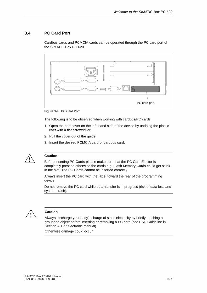
3.4 PC Card Port
Cardbus cards and PCMCIA cards can be operated through the PC card port ofthe SIMATIC Box PC 620.
PC card port
Figure 3-4 PC Card Port
The following is to be observed when working with cardbus/PC cards:
1. Open the port cover on the left–hand side of the device by undoing the plasticrivet with a flat screwdriver.
2. Pull the cover out of the guide.
3. Insert the desired PCMCIA card or cardbus card.
!Caution
Before inserting PC Cards please make sure that the PC Card Ejector iscompletely pressed otherwise the cards e.g. Flash Memory Cards could get stuckin the slot. The PC Cards cannot be inserted correctly.
Always insert the PC card with the label toward the rear of the programmingdevice.
Do not remove the PC card while data transfer is in progress (risk of data loss andsystem crash).
!Caution
Always discharge your body’s charge of static electricity by briefly touching agrounded object before inserting or removing a PC card (see ESD Guideline inSection A.1 or electronic manual).
Otherwise damage could occur.
Welcome to the SIMATIC Box PC 620
3-8SIMATIC Box PC 620 Manual
C79000-G7076-C639-04
Note
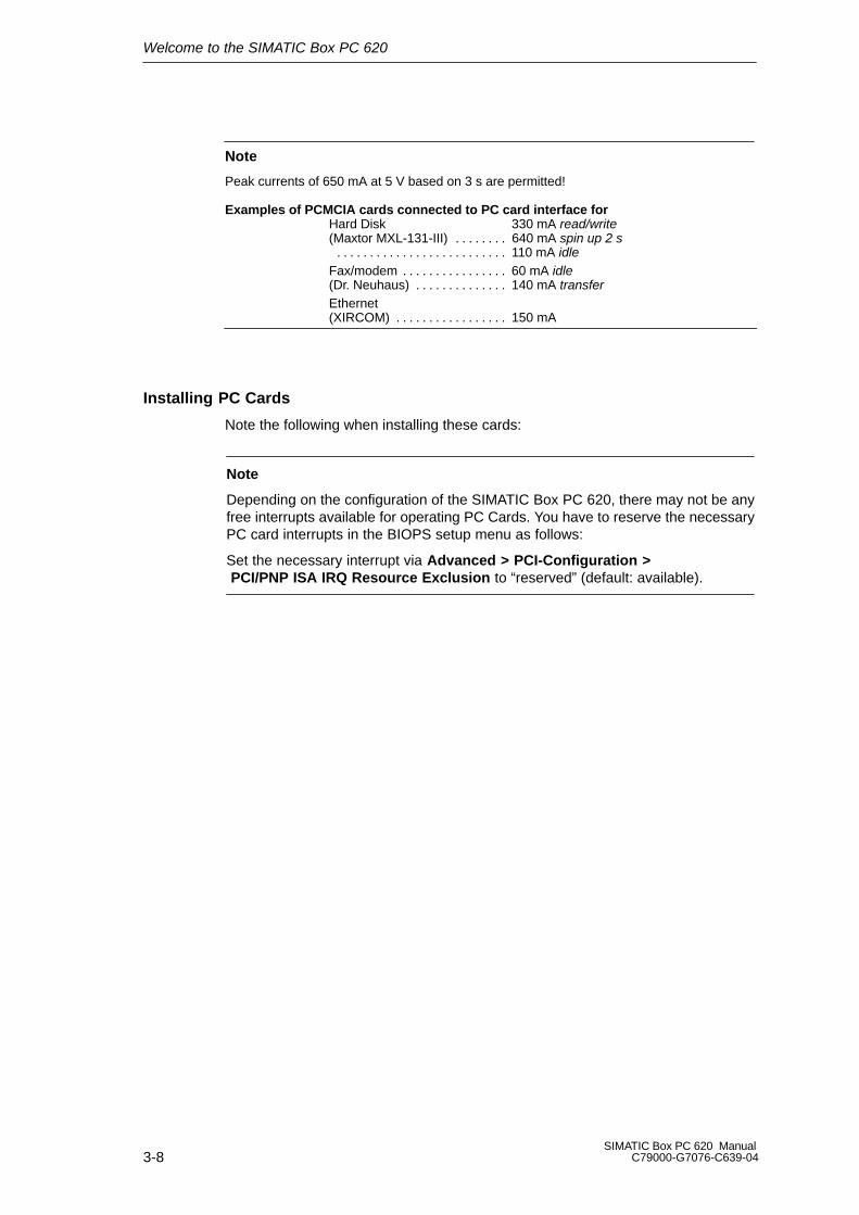
Peak currents of 650 mA at 5 V based on 3 s are permitted!
Examples of PCMCIA cards connected to PC card interface forHard Disk 330 mA read/write(Maxtor MXL-131-III) 640 mA spin up 2 s. . . . . . . .
110 mA idle. . . . . . . . . . . . . . . . . . . . . . . . . . Fax/modem 60 mA idle. . . . . . . . . . . . . . . . (Dr. Neuhaus) 140 mA transfer. . . . . . . . . . . . . . Ethernet(XIRCOM) 150 mA. . . . . . . . . . . . . . . . .
Installing PC Cards
Note the following when installing these cards:
Note
Depending on the configuration of the SIMATIC Box PC 620, there may not be anyfree interrupts available for operating PC Cards. You have to reserve the necessaryPC card interrupts in the BIOPS setup menu as follows:
Set the necessary interrupt via Advanced > PCI-Configuration > PCI/PNP ISA IRQ Resource Exclusion to “reserved” (default: available).

Welcome to the SIMATIC Box PC 620
3-9SIMATIC Box PC 620 ManualC79000-G7076-C639-04
3.5 Drives
The SIMATIC Box PC 620 is equipped as standard with a 3.5” disk drive or anLS120 drive and a 3.5” hard disk drive.
3.5.1 Disk Drive (Depending on the Device Configuration)
You can store programs and data on diskettes with the disk drive and load themfrom diskettes into the SIMATIC Box PC 620.
Types of Diskette
You can use following diskettes:
Double Sided High Density Diskette Double Sided Double Density Diskette
3.5 in. 3.5 in.
1.44 Mbytes (135 TPI) 720 Kbytes
Handling Diskettes with the Floppy Disk Drive
The diskette is inserted in the disk drive as shown below:
Access LED Ejector
Access LED
Figure 3-5 Handling Disks
When the floppy disk drive is being accessed, the access indicator light is lit.
!Caution
Risk of loss of data!
When the green access LED of the floppy disk drive is lit, the ejector may not beactuated.

Welcome to the SIMATIC Box PC 620
3-10SIMATIC Box PC 620 Manual
C79000-G7076-C639-04
3.5.2 LS 120 Drive (Depending on Device Configuration)
The SIMATIC Box PC 620 can be equipped with an LS 120 drive as an alternativeto a floppy disk drive.
Larger volumes of data can be stored on LS 120 data carriers than on a1.44 MB floppy disk drive. The LS 120 has the following features:
– The LS 120 is compatible with a 1.44 MB floppy disk drive,i.e. 1.44 MByte disks can also be processed.
– An LS 120 data carrier has a maximum data volume of 120 MBytes.
– The LS 120 is connected via an ATAPI (IDE) port.
Handling Disks with the LS 120 Drive
Depending on the fitting position, the disks are inserted into the disk drive as illu-strated below:
Access hole for emergency ejection (only LS120)
Ejector
EjectorAccess LED
Access LED
Figure 3-6 Handling Disks
When the LS 120 drive is being accessed, the access indicator light is lit.
Emergency ejection is carried out in the same way with the LS120 as in the CD-ROM drive. See Section 3.4.4. for details.
!Caution
Risk of loss of data!
When the green access LED of the LS 120 drive is lit, the ejector may not beactuated.
LS 120 drives are very sensitive to shocks of a non-permissible level. Shocks during operation can lead to damage to the drive or the data carrier. You can findthe permissible values in the technical data in Section 7.1.
Welcome to the SIMATIC Box PC 620
3-11SIMATIC Box PC 620 ManualC79000-G7076-C639-04
3.5.3 Hard Disk Drive
The hard disk drive is used for the storage of large quantities of data. it is fitted in amounting which is easily exchangeable and damped against vibration.
!CautionRisk of loss of data and damage to the drive!!
Drives are sensitive to vibrations and shock. Any vibrations occurring duringoperation can lead to the loss of data or damage to the drive.
If you intend transporting the unit, switch it off, and wait until the drive has come torest (about 20 seconds) before you move it.
3.5.4 CD-ROM Drive (Depending on the Device Equipment)
Depending on the device equipment, a CD-ROM drive is fitted in the SIMATIC Box PC 620. The fitting depth of the PC is increased by 20 mm as a re-sult. The CD-ROM drive allows you to read CDs.
Opening the Drawer
By briefly pressing the eject button, the drawer springs out slightly. Now pull thedrawer out until it clicks into position.
Inserting / Removing CDs
Now insert the CD in the drawer with the labeling face up, and press it firmly downinto the center of the turntable. To remove the CD, hold it by the edges and pullupwards.
!Caution
To avoid too much pressure on the open drawer, always hold the drawer at thefront with one hand when inserting or removing a CD.

Welcome to the SIMATIC Box PC 620
3-12SIMATIC Box PC 620 Manual
C79000-G7076-C639-04
Closing the Drawer
Push in the drawer until it closes completely. Do not press the eject button.
Note
The EJECT function offered by various applications for opening the CD ROMdrawer does not work with this drive.
After the drawer has been closed, the CD is tested and the access display light onthe drive starts to flash:
– If the display flashes continually, the CD is faulty but can still be read,
– If the display flashes several times and then remains lit, the CD you haveinserted is defective and cannot be read.
Welcome to the SIMATIC Box PC 620
3-13SIMATIC Box PC 620 ManualC79000-G7076-C639-04
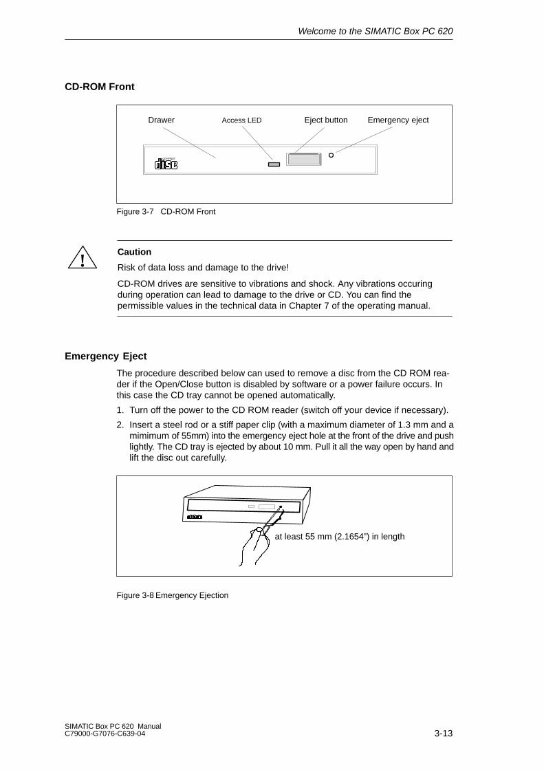
CD-ROM Front
Emergency ejectDrawer Eject buttonAccess LED
Figure 3-7 CD-ROM Front
!Caution
Risk of data loss and damage to the drive!
CD-ROM drives are sensitive to vibrations and shock. Any vibrations occuringduring operation can lead to damage to the drive or CD. You can find the permissible values in the technical data in Chapter 7 of the operating manual.
Emergency Eject
The procedure described below can used to remove a disc from the CD ROM rea-der if the Open/Close button is disabled by software or a power failure occurs. Inthis case the CD tray cannot be opened automatically.
1. Turn off the power to the CD ROM reader (switch off your device if necessary).
2. Insert a steel rod or a stiff paper clip (with a maximum diameter of 1.3 mm and amimimum of 55mm) into the emergency eject hole at the front of the drive and pushlightly. The CD tray is ejected by about 10 mm. Pull it all the way open by hand andlift the disc out carefully.
at least 55 mm (2.1654”) in length
Figure 3-8 Emergency Ejection
Welcome to the SIMATIC Box PC 620
3-14SIMATIC Box PC 620 Manual
C79000-G7076-C639-04
3.6 Backup Battery
A backup battery (3.6 V lithium battery) powers the hardware clock even after theprogramming device is switched off.
There is a battery on the motherboard in this device. Batteries may only beexchanged by technical personnel. Note the information in the documentation ofthe CPU module! Observe the local regulations on the disposal of special wastewhen disposing of dead batteries.
!Caution
There is the danger of an explosion if the battery is not exchanged as directed.Replace only with the same type or an equivalent type recommended by themanufacturer. Dispose of used batteries in accordance with the manufacturer’sinstructions.
!WarningRisk of severe personal injury or property damage, danger of release of harmfulsubstances.
There may be a danger of explosion if the battery is not handled properly.Incorrect disposal of used batteries can cause the release of harmful substances.
Do not throw a new or discharged lithium battery into an open fire, do not solderonto the cell container. Do not recharge the battery, do not open the battery byforce.
The correct lithium battery is available from Siemens (order no.: W79084-E1003-B1).
Return used batteries to the manufacturer/recycler or dispose of them according tolocal regulations.
4-1SIMATIC Box PC 620 ManualC79000-G7076-C639-04
Setting Up and Operating theSIMATIC Box PC 620
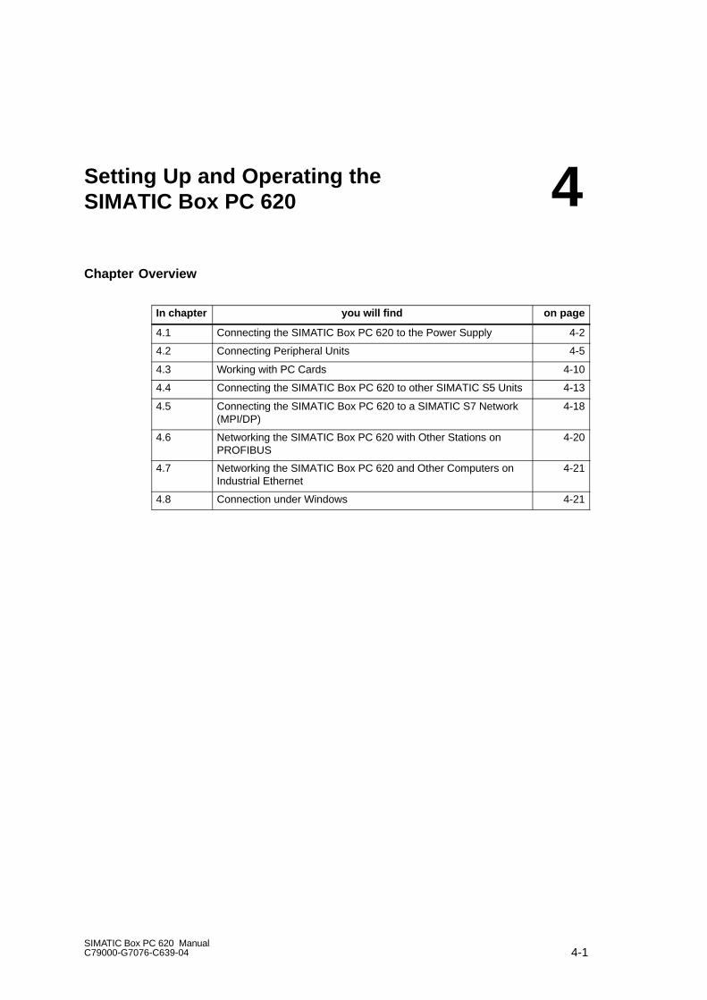
Chapter Overview
In chapter you will find on page
4.1 Connecting the SIMATIC Box PC 620 to the Power Supply 4-2
4.2 Connecting Peripheral Units 4-5
4.3 Working with PC Cards 4-10
4.4 Connecting the SIMATIC Box PC 620 to other SIMATIC S5 Units 4-13
4.5 Connecting the SIMATIC Box PC 620 to a SIMATIC S7 Network(MPI/DP)
4-18
4.6 Networking the SIMATIC Box PC 620 with Other Stations onPROFIBUS
4-20
4.7 Networking the SIMATIC Box PC 620 and Other Computers onIndustrial Ethernet
4-21
4.8 Connection under Windows 4-21
4
Setting Up and Operating the SIMATIC Box PC 620
4-2SIMATIC Box PC 620 Manual
C79000-G7076-C639-04
4.1 Connecting the SIMATIC Box PC 620 to the Power Supply
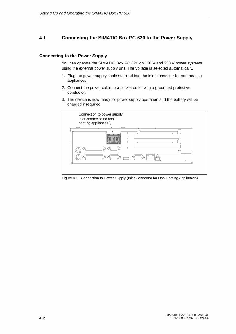
Connecting to the Power Supply
You can operate the SIMATIC Box PC 620 on 120 V and 230 V power systemsusing the external power supply unit. The voltage is selected automatically.
1. Plug the power supply cable supplied into the inlet connector for non-heatingappliances
2. Connect the power cable to a socket outlet with a grounded protectiveconductor.
3. The device is now ready for power supply operation and the battery will becharged if required.
Connection to power supplyInlet connector for non-heating appliances
Figure 4-1 Connection to Power Supply (Inlet Connector for Non-Heating Appliances)

Setting Up and Operating the SIMATIC Box PC 620
4-3SIMATIC Box PC 620 ManualC79000-G7076-C639-04
Power Connection
The device is intended for poeration in grounded electricity supply systems(TN systems to VDE 0100 part 300 or IEC 364-3).
Service in non-grounded or impedance-grounded supply systems (IT systems) isnot intended.
The power line should meet the respective local safety requirements.
Check whether the device’s set supply voltage is the same as the local supply voltage.
This device is equipped with a safety-tested power supply cable. You may connectthis device only to a grounding outlet with a grounding contact.
Make certain that the socket outlet on the device or the grounding contact for thebuilding wiring system is freely accessible and as near to the device as possible.
The mains switch does not separate the device from the power system. To establish a complete power separation, you must disconnect the power plug (inletconnector on the back of the device). This location must be accessible. A centralisolating switch must be present for cabinet mounting.
Install the cables so that no one can step on them or trip over them. When youconnect the device, adhere to the relevant instructions in Chapter 2 of this manual.
Do not connect or disconnect power supply cables and data transmission lines during thunderstorms.
In emergency situations (for example, damaged housing, damaged operatorelements, a damaged power supply cable, ingress of liquids or foreign particles),switch off the device. Disconnect the power plug and inform the responsible service personnel.
The SIMATIC Box PC 620 must be switched off when you connect or disconnectI/O devices (keyboard, mouse, printer, etc.). You can damage the PC if you do notadhere to these instructions.
When plugging in/unplugging peripheral connections (keyboard, mouse, printeretc.) the SIMATIC box PC 620 must be switched off (not for PC-Card and USB-devices). In the case of non-observance, this can lead to damage to the PC.

Setting Up and Operating the SIMATIC Box PC 620
4-4SIMATIC Box PC 620 Manual
C79000-G7076-C639-04
Country-Specific Information
For the United States and Canada:
In the United States and Canada USA, a CSA or UL-listed power supply cablemust be used.
The male plug is a 5-15 style.
For Operation with 120 V:
Use a UL Listed, CSA Labelles Cord Set, consisting of a min. 18 AWG. Type SVTor STJ three conductor flexible cord, max. 4.5 m (15 feet) in length and a parallelblade grounding type attachment plug rated 15 A, min 125 V.
For Operation with 240 V:
Use a UL Listed, CSA Labelled Cord Set, consisting od a min. 18 AWG. Type SVTor SJT three conductor flexible cord, max. 4.5 m (15 feet) in length and a tandemblade grounding type attachment plug, rated 15 A, 250 V.
For Operation with 230 V (outside of USA and Canada)
Use a Cord Set consisting of a min 18 AWG cord and grounding type attachmentplug rated 15 A, 250 V. The cord set should have the approviate safety approvalsfor the country in which the equipment will be installed and marked.
Setting Up and Operating the SIMATIC Box PC 620
4-5SIMATIC Box PC 620 ManualC79000-G7076-C639-04
4.2 Connecting Peripheral Devices
Note
When connecting peripheral units, ensure that the components have industrial capability
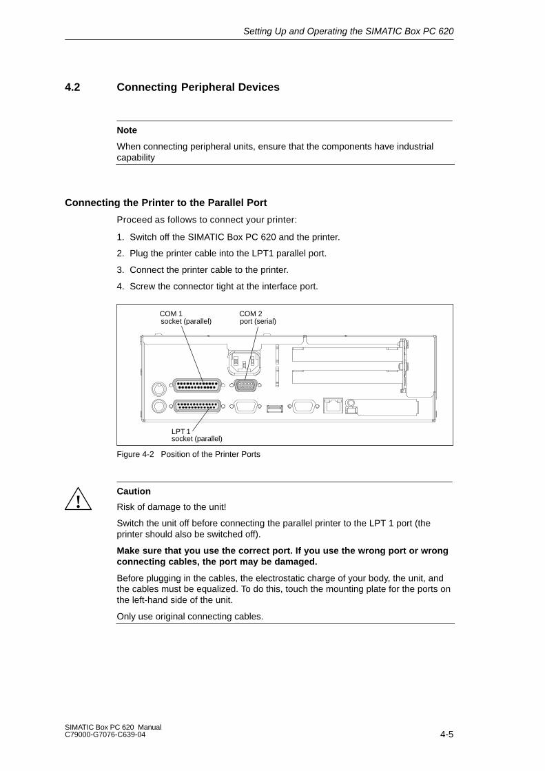
Connecting the Printer to the Parallel Port
Proceed as follows to connect your printer:
1. Switch off the SIMATIC Box PC 620 and the printer.
2. Plug the printer cable into the LPT1 parallel port.
3. Connect the printer cable to the printer.
4. Screw the connector tight at the interface port.
COM 1 COM 2
LPT 1socket (parallel)
socket (parallel) port (serial)
Figure 4-2 Position of the Printer Ports
!Caution
Risk of damage to the unit!
Switch the unit off before connecting the parallel printer to the LPT 1 port (theprinter should also be switched off).
Make sure that you use the correct port. If you use the wrong port or wrongconnecting cables, the port may be damaged.
Before plugging in the cables, the electrostatic charge of your body, the unit, andthe cables must be equalized. To do this, touch the mounting plate for the ports onthe left-hand side of the unit.
Only use original connecting cables.
Setting Up and Operating the SIMATIC Box PC 620
4-6SIMATIC Box PC 620 Manual
C79000-G7076-C639-04
Connecting the Printer to the Serial Port
You can also connect your printer to the SIMATIC Box PC using a serial COM port.You will find information on how to adapt and set your interface and which connect-ing cable you require in the description of your printer.
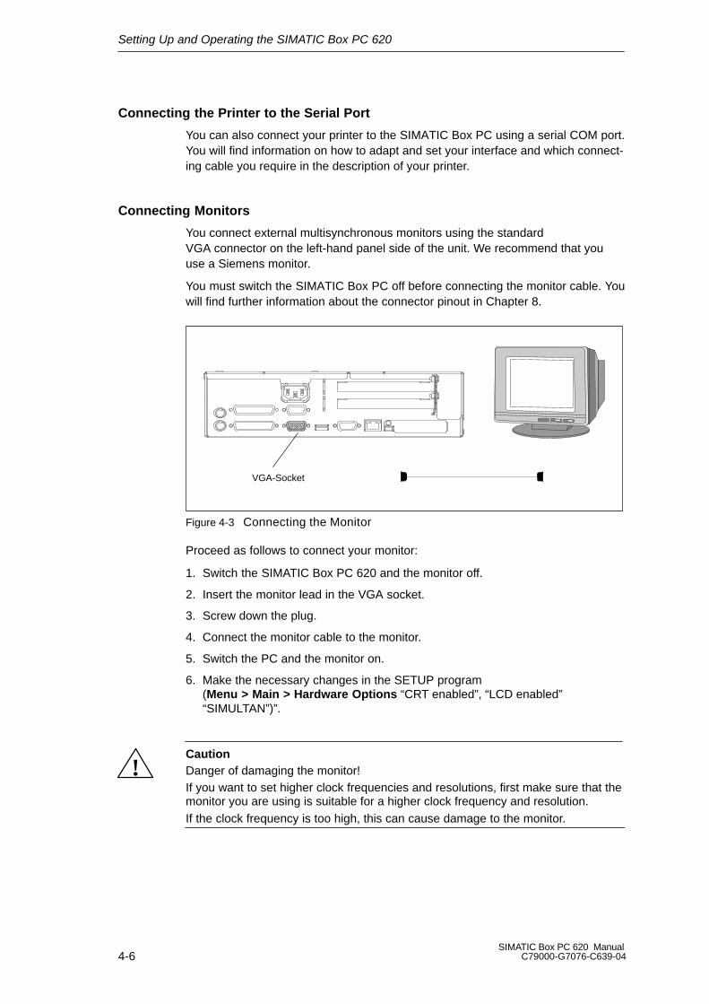
Connecting Monitors
You connect external multisynchronous monitors using the standardVGA connector on the left-hand panel side of the unit. We recommend that youuse a Siemens monitor.
You must switch the SIMATIC Box PC off before connecting the monitor cable. Youwill find further information about the connector pinout in Chapter 8.
VGA-Socket
Figure 4-3 Connecting the Monitor
Proceed as follows to connect your monitor:
1. Switch the SIMATIC Box PC 620 and the monitor off.
2. Insert the monitor lead in the VGA socket.
3. Screw down the plug.
4. Connect the monitor cable to the monitor.
5. Switch the PC and the monitor on.
6. Make the necessary changes in the SETUP program(Menu > Main > Hardware Options “CRT enabled”, “LCD enabled”“SIMULTAN”)”.
!CautionDanger of damaging the monitor!If you want to set higher clock frequencies and resolutions, first make sure that themonitor you are using is suitable for a higher clock frequency and resolution.If the clock frequency is too high, this can cause damage to the monitor.
Setting Up and Operating the SIMATIC Box PC 620
4-7SIMATIC Box PC 620 ManualC79000-G7076-C639-04
Using a Mouse
You can connect both a PS/2-USB and a serial mouse to theSIMATIC Box PC 620.
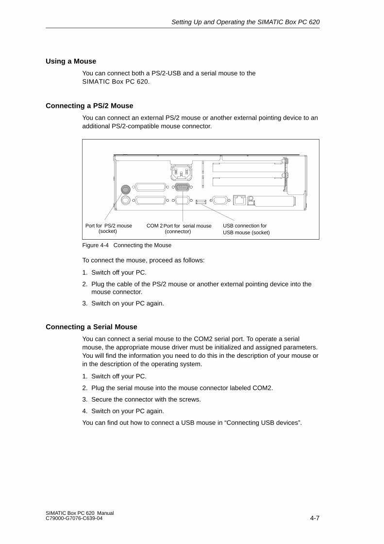
Connecting a PS/2 Mouse
You can connect an external PS/2 mouse or another external pointing device to anadditional PS/2-compatible mouse connector.
Port for PS/2 mouse(socket)
COM 2 Port for serial mouse(connector)
USB connection forUSB mouse (socket)
Figure 4-4 Connecting the Mouse
To connect the mouse, proceed as follows:
1. Switch off your PC.
2. Plug the cable of the PS/2 mouse or another external pointing device into themouse connector.
3. Switch on your PC again.
Connecting a Serial Mouse
You can connect a serial mouse to the COM2 serial port. To operate a serialmouse, the appropriate mouse driver must be initialized and assigned parameters.You will find the information you need to do this in the description of your mouse orin the description of the operating system.
1. Switch off your PC.
2. Plug the serial mouse into the mouse connector labeled COM2.
3. Secure the connector with the screws.
4. Switch on your PC again.
You can find out how to connect a USB mouse in “Connecting USB devices”.
Setting Up and Operating the SIMATIC Box PC 620
4-8SIMATIC Box PC 620 Manual
C79000-G7076-C639-04
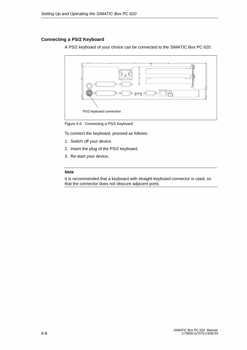
Connecting a PS/2 Keyboard
A PS/2 keyboard of your choice can be connected to the SIMATIC Box PC 620.
PS/2 keyboard connection
Figure 4-5 Connecting a PS/2 Keyboard
To connect the keyboard, proceed as follows:
1. Switch off your device.
2. Insert the plug of the PS/2 keyboard.
3. Re-start your device.
Note
It is recommended that a keyboard with straight keyboard connector is used, sothat the connector does not obscure adjacent ports.
Setting Up and Operating the SIMATIC Box PC 620
4-9SIMATIC Box PC 620 ManualC79000-G7076-C639-04
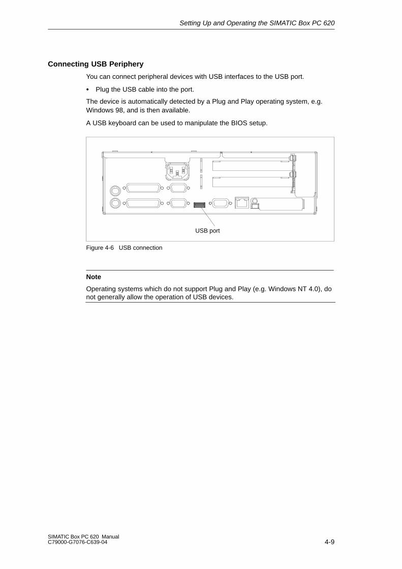
Connecting USB Periphery
You can connect peripheral devices with USB interfaces to the USB port.
Plug the USB cable into the port.
The device is automatically detected by a Plug and Play operating system, e.g.Windows 98, and is then available.
A USB keyboard can be used to manipulate the BIOS setup.
USB port
Figure 4-6 USB connection
Note
Operating systems which do not support Plug and Play (e.g. Windows NT 4.0), donot generally allow the operation of USB devices.

Setting Up and Operating the SIMATIC Box PC 620
4-10SIMATIC Box PC 620 Manual
C79000-G7076-C639-04
4.3 Working with PC Cards
PC Cards
The PC card interface supports Cardbus-Cards (32 Bit) and PCMCIA-Cards(16 Bit). The SIMATIC Box PC 620 has one PC card port. You can plug commu-nication modules for MODEM, FAX-MODEM, ISDN, Token Ring, ETHERNET,memory expansion and SCSI interface modules in credit-card format into theseports.
PC card interface, type I/II/III
Figure 4-7 PC Card Interface
The following is to be observed when working with cardbus/PC cards:
1. Open the port cover on the left–hand side of the device by undoing the plasticrivet with a flat screwdriver.
2. Pull the cover out of the guide.
3. Insert the desired PCMCIA card or cardbus card.
!Caution
Before inserting PC-Cards please make sure that the PC-Card Ejector iscompletely pressed otherwise the cards e.g. Flash Memory Cards could get stuckin the slot. The PC-Cards cannot be inserted correctly.
Always insert the PC card with the label toward the rear of the programming device.
Do not remove the PC card while data transfer is in progress (risk of data loss andsystem crash).

Setting Up and Operating the SIMATIC Box PC 620
4-11SIMATIC Box PC 620 ManualC79000-G7076-C639-04
!CautionBefore plugging in or taking out Cardbus/PC cards, you must discharge theelectrostatic of your body by briefly touching grounded object (ESD guidelines,Section A.1).
Otherwise faults can occur.
Note
Surge currents of 650 mA at 5 V relating to 3 s are allowable!
Examples of PCMCIA cards connected to PC card interface forHard Disk 330 mA read/write(Maxtor MXL-131-III) 640 mA spin up 2 s. . . . . . . .
110 mA idle. . . . . . . . . . . . . . . . . . . . . . . . . . Fax/modem 60 mA idle. . . . . . . . . . . . . . . . (Dr. Neuhaus) 140 mA transfer. . . . . . . . . . . . . . Ethernet(XIRCOM) 150 mA. . . . . . . . . . . . . . . . .
Installing PC Cards
Note the following when installing these cards:
Note
Depending on the configuration of the SIMATIC Box PC 620, there may not be anyfree interrupts available for operating PC Cards. You have to reserve the necessaryPC card interrupts in the BIOPS setup menu as follows:
Set the necessary interrupt via Advanced > PCI-Configuration > PCI/PNP ISA IRQ Resource Exclusion to “reserved” (default: available).

Setting Up and Operating the SIMATIC Box PC 620
4-12SIMATIC Box PC 620 Manual
C79000-G7076-C639-04
!Caution
Risk of damage to PC cards and the SIMATIC Box PC 620!
Always insert PC cards with the front face turned toward the rear of the SIMATICBox PC 620. The front face generally bears the company and product designationand is labeled ”This side up”, or words to that effect.
You might damage the SIMATIC Box PC 620 and the PC card if you attempt toinsert the PC card the wrong way round.
Before inserting the connecting cables, the electrostatic charge in your body, thedevice and the connecting cables must be brought to the same potential. Brieflytouch the sheet metal case to do this.
Note
In order to use a PC card the BIOS-SETUP Main > Hardware Option“Cardbus/PCMCIA Slot” has to be set to “Enabled”.

Setting Up and Operating the SIMATIC Box PC 620
4-13SIMATIC Box PC 620 ManualC79000-G7076-C639-04
4.4 Connecting the SIMATIC Box PC 620 to other SIMATIC S5
Point-To-Point Connection
In this section, you will learn how to connect your SIMATIC Box PC 620 to aprogramming device or S5 programmable logic controller using a point-to-pointconnection.
You can stablish a point-to-point connection by connecting theSIMATIC Box PC 620 to another programming device or a programmable logiccontroller using
A V.24 connection
A TTY connection (not possible for the basic variant of the Box PC)
Configuring Interfaces with Line Current (TTY, 20 mA)
To ensure reliable data transfer, several factors must be taken into account. Themaximum data transfer rate (baud rate) depends on the distance, the type ofcable, the pin assignment of the interface and external interference.
You can reduce interference by choosing the right transmission cable andconnecting it properly, and by observing the following guidelines:
Use a shielded cable with a low line resistance (130 / km) (about 40 kft)and low capacitance (< 90 pF/m) (about 27 pF/ft). Twisted-pair cables are lesssusceptible to noise and interference. A low line resistance results in reducedvoltage excursions and shorter charge reversal times. The line resistance de-creases with increasing conductor cross-section for the same length of cable.
The shorter the transmission link, the higher the maximum possible datatransfer rate.
If there is an active sender and an active receiver at the same end of thetransmission link, the sequence of access priority to the transmission circuitmust be taken into account in order to achieve the longest possibletransmission link.
Signal lines and power lines must not run together. Signal lines must beinstalled as far away as possible from sources of strong interference (forexample, 400 V 3-phase power cables).
The active TTY interface with a 12 V no-load voltage has been tested on a 100m (1100 ft) long cable at a transmission rate of 9600 bps in an environment withnormal levels of noise fieldstrengthV/mor1V/ft).If a shielded 5 x 1 x 0.14shieldedcable is used, reliable transmission is possible over a distance of up to 100 m(1100 ft). The AS511 protocol (only one transmitter at a time) was used fortesting.
Note
The interference field of the source of interference is reduced by the square of thedistance.

Setting Up and Operating the SIMATIC Box PC 620
4-14SIMATIC Box PC 620 Manual
C79000-G7076-C639-04
Connecting the SIMATIC Box PC 620 to an S5 Programmable Logic Controller
You can connect the SIMATIC Box PC 620 to a SIMATIC S5 programmable logiccontroller using the COM1/TTY interface port. The cable for connecting to SIMATIC S5 CPUs is supplied with the SIMATIC Box PC 620 (Order no.:6ES5734-2BD20).
COM 1(socket)
Figure 4-8 Connecting the SIMATIC Box PC 620 to an S5 Programmable Logic Controller
You connect your SIMATIC Box PC 620 to a SIMATIC S5 programmable logiccontroller as follows:
1. Switch off your device.
2. Insert the connecting cable into the portCOM 1 / AG.
3. Screw down the plug.
4. Plug the cable into the corresponding port on the CPU of the programmablelogic controller.
5. In order to enable TTY operation, you must set TTY to “enabled” in the BIOSsetup.
!Caution
Risk of damage to the Simatic Box PC 620!
The interface port may be damaged if you confuse the connections or use thewrong connecting cables.
Make sure the TTY cable of the SIMATIC Box PC 620is plugged into theCOM 1 / TTY port and not into the LPT 1 port.
Before inserting the connecting cables, the electrostatic charge in your body, thedevice and the connecting cables must be brought to the same potential. Brieflytouch the sheet metal case to do this.
Use only original cables to stablish the connection to the programmable controller.

Setting Up and Operating the SIMATIC Box PC 620
4-15SIMATIC Box PC 620 ManualC79000-G7076-C639-04
Connecting the SIMATIC Box PC 620 via an Adapter
The connecting cable 6ES5 734-2BD20 is supplied with theSIMATIC Box PC 620. An adapter is available for connecting the programmablecontroller using old standard cables.
Tabelle 4-1 Adapter for SIMATIC Box PC 620 Connection
Interface Link Connecting Cable
Order no:
Adapter
6ES5 734-2BD20
TTY interface SIMATIC Box PC 620 to SIMATIC-6ES5 731-1xxx015–pin
6ES5 731-6AG00
(COM 1) S5 programmable controller6ES5 731-0xxx025– pin
6ES5 731-6AG00
In order to maintain a data transfer rate of 9600 bps up to a distance of over1000 m (3300 ft), the receiving diode is connected to ground (reference) via theconnecting cable
NoteYou can obtain lengths differing from the standard connecting cable(6ES5 734-2BD20) under the order number 6ES5 734-2xxx0, whereby xxx standsfor the length code.

Setting Up and Operating the SIMATIC Box PC 620
4-16SIMATIC Box PC 620 Manual
C79000-G7076-C639-04
SIMATIC Box PC 620 to PG Connection (V.24, TTY)
If you want to connect your SIMATIC Box PC 620 to another programming device,you can plug the appropriate connecting cable into the V.24 or TTY interface port
Tabelle 4-2 Connection of the SIMATIC Box PC 620 to other PUs
Interface Link Connecting CableOrder No.:
Adapter
COM 1 as aV.24 port
PG 7xx with PG 7xx 6ES5 733-5BD202)
COM 1 as aTTY port
PG 7xx with PG 6xx Series connection of6ES5733-2xxx02)
and6ES5731-6AG001)
6ES5 731-6AG00
Note1. When connecting the programming devices in series, make sure you connect the cable
the right way around (see Figure 4-9).
2. The connecting cable is available for order only as a spare part. The connecting cable isdescribed in Chapter 8.
Adapter Connecting cableActive Passive
6ES5 731–6AG00 6ES5 733–2xxx0
PG 7XX PG 6XX
Figure 4-9 Direction of Connection: Adapter – Connecting Cable
NoteFor the PC/PU connection, you must switch the TTY ports (COM 1) in one of theprogrammable logic controllers to passive by changing the jumper setting. Whenthe SIMATIC Box PC 620 leaves the factory, this interface is always set to active!
Setting Up and Operating the SIMATIC Box PC 620
4-17SIMATIC Box PC 620 ManualC79000-G7076-C639-04
Switching the SIMATIC Box PC 620 to Active/Passive
When your SIMATIC Box PC 620 is supplied, the COM1 (TTY) serial port is active(20 mA current loop). When you connect two programming devices using theCOM1 (TTY) serial port, you must deactivate the port on one of these devices. Inthe SIMATIC Box PC 620, the switch for this is located on the motherboard.
These jumpers are accessible if you open the battery compartment cover.
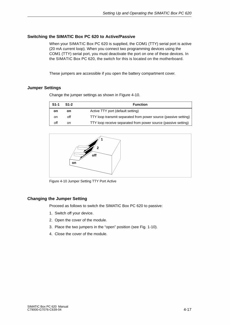
Jumper Settings
Change the jumper settings as shown in Figure 4-10.
S1-1 S1-2 Function
on on Active TTY port (default setting)
on off TTY loop transmit separated from power source (passive setting)
off on TTY loop receive separated from power source (passive setting)
on
off
1
2
Figure 4-10 Jumper Setting TTY Port Active
Changing the Jumper Setting
Proceed as follows to switch the SIMATIC Box PC 620 to passive:
1. Switch off your device.
2. Open the cover of the module.
3. Place the two jumpers in the “open” position (see Fig. 1-10).
4. Close the cover of the module.
Setting Up and Operating the SIMATIC Box PC 620
4-18SIMATIC Box PC 620 Manual
C79000-G7076-C639-04
4.5 Connecting the SIMATIC Box PC 620 to a SIMATIC S7 Network (MPI/DP)
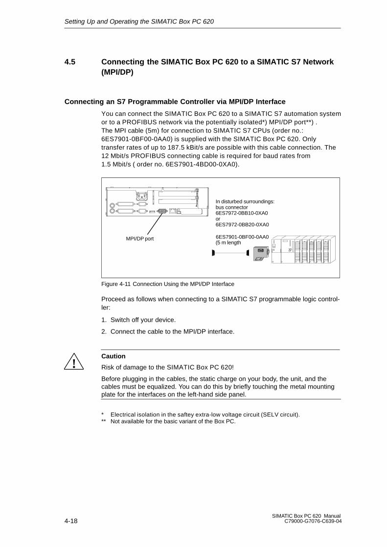
Connecting an S7 Programmable Controller via MPI/DP Interface
You can connect the SIMATIC Box PC 620 to a SIMATIC S7 automation systemor to a PROFIBUS network via the potentially isolated*) MPI/DP port**) .The MPI cable (5m) for connection to SIMATIC S7 CPUs (order no.: 6ES7901-0BF00-0AA0) is supplied with the SIMATIC Box PC 620. Onlytransfer rates of up to 187.5 kBit/s are possible with this cable connection. The12 Mbit/s PROFIBUS connecting cable is required for baud rates from1.5 Mbit/s ( order no. 6ES7901-4BD00-0XA0).
MPI/DP port 6ES7901-0BF00-0AA0
In disturbed surroundings:bus connector6ES7972-0BB10-0XA0 or 6ES7972-0BB20-0XA0
(5 m length
Figure 4-11 Connection Using the MPI/DP Interface
Proceed as follows when connecting to a SIMATIC S7 programmable logic control-ler:
1. Switch off your device.
2. Connect the cable to the MPI/DP interface.
!Caution
Risk of damage to the SIMATIC Box PC 620!
Before plugging in the cables, the static charge on your body, the unit, and thecables must be equalized. You can do this by briefly touching the metal mountingplate for the interfaces on the left-hand side panel.
* Electrical isolation in the saftey extra-low voltage circuit (SELV circuit).** Not available for the basic variant of the Box PC.
Setting Up and Operating the SIMATIC Box PC 620
4-19SIMATIC Box PC 620 ManualC79000-G7076-C639-04
Connecting
Via the MPI/DP interface, you can connect your PC to
MPI networks (S7-200, S7-300, and S7-400) or
PROFIBUS DP networks (DP components).
MPI/PROFIBUS Network
Up to 32 devices (PC, programming device, or programmable controller) can beconnected to the MPI/DP interface to form a network segment. The physical connection to the MPI/PROFIBUS DP network is via a floating RS485 interfacewhich is a component of the PC basic module.
Several MPI/PROFIBUS DP network segments can be connected via repeaters.The complete MPI/PROFIBUS DP network can comprise up to 127 stations. Datatransmission rates from 9.6 Kbps to 12 Mbps are possible in thePROFIBUS DP MPI network.
Note
You will find more information on setting up an MPI/DP network in the manual”PROFIBUS Networks” Order No.: 6GK 1970-5CA10-0AA0 or in SIMATIC NET.
Setting Up and Operating the SIMATIC Box PC 620
4-20SIMATIC Box PC 620 Manual
C79000-G7076-C639-04
4.6 Networking the SIMATIC Box PC 620 with Other Stations onPROFIBUS
Networking the SIMATIC Box PC 620 on PROFIBUS
PROFIBUS is an open and robust bus system for industrial use. It can be used toconfigure networks with up to 32 stations per segment. PROFIBUS-DP supportsdata-transfer rates from 9.6 Kbaud to 12 Mbaud.
How the Network Functions
The network operates on the master-slave principle with token passing (complyingwith DIN19245, PROFIBUS). It distinguishes between active and passive stations.An active station receives the token and passes it on to the next station within aspecified time.
Hardware Requirements
Using the following components, for example, you can connect or network the SIMATIC Box PC 620 with PROFIBUS:
RS 485 MPI/DP interface adapter (not available for the basic variant of theBox PC)
Shielded, twisted pair (bus cable or connecting cable to network).
Note
You will find more detailed information about the SIMATIC Net PC cards in theSIMATIC NET Catalog IK 10.
Setting Up and Operating the SIMATIC Box PC 620
4-21SIMATIC Box PC 620 ManualC79000-G7076-C639-04
4.7 Networking the SIMATIC Box PC 620 and Other Computers onIndustrial Ethernet
Networking the SIMATIC Box PC 620 on Industrial Ethernet
Industrial Ethernet is a bus system for industrial use based on Ethernet(ISO 8802/3). The main features of Industrial Ethernet are:
speed (10 Mbps), simple expansion, open communication, and widespreadapplication.
How the Network Functions
Industrial Ethernet is the name of Siemens networks and network componentsoperating according to the CSMA / CD (Ethernet) principle. Industrial Ethernet is abus-type LAN that uses a triaxial cable (H1) as its transmission medium.
Note
You will find more detailed information about the SIMATIC Net PC cards in theSIMATIC NET Catalog IK 10.
4.8 Connection under Windows
Windows supports point-to-point connections via the LPT or COM port. Theconnecting cables are standard, commercially available products. More informationis available in the Networks section of the Windows description and in the onlineHelp system under “Connection to Another Computer”.

Setting Up and Operating the SIMATIC Box PC 620
4-22SIMATIC Box PC 620 Manual
C79000-G7076-C639-04

5-1SIMATIC Box PC 620 ManualC79000-G7076-C639-04
SIMATIC Box PC 620 Expansions
What Does This Chapter Contain?
You can enhance the performance of your SIMATIC Box PC 620 by addingadditional memory. This chapter describes how to expand yourSIMATIC Box PC 620. Please observe the relevant safety guidelines.
Chapter Overview
In chapter you will find on page
5.1 Opening the Unit 5-2
5.2 Installation of a Memory Extension 5-5
5.3 Replacing the Backup Battery 5-6
5.4 Installation of Expansion Cards 5-13
5.5 Removal and Installation of Drives 5-18
5.6 Removal and Installation of the Power Supply Unit 5-23
5.7 Removal and Installation of the Bus Board 5-24
5.8 Removal and Installation of the Fan 5-26
5.9 Processor upgrade 5-27
5.10 Switch Adjustment / Jumpers 5-28
5.11 Reset Button 5-29
5
SIMATIC Box PC 620 Expansions
5-2SIMATIC Box PC 620 Manual
C79000-G7076-C639-04
5.1 Opening the Unit
5.1.1 Prerequisites
The device is designed for easy maintenance so that any work that is necessarycan be done quickly and at low cost.
!Caution
The electronic components on the printed circuit boards are extremely sensitive toelectrostatic discharge. Certain precautionary measures are therefore necessarywhen handling such components. These measures are explained in the guidelinesfor handling electrostatically sensitive devices at the end of this manual.
Limitation of Liability
All technical specifications and licences apply only to expansion functions approved by SIEMENS.
No liability can be accepted for impairment of functions caused by the use of devices and components of other manufacturers.
All the modules and components in the SIMATIC Box PC 620 are electrostaticallysensitive. Please read the ESD guidelines at the end of this book carefully. Thefollowing symbol warns that electrostatically-sensitive modules are present.
SIMATIC Box PC 620 Expansions
5-3SIMATIC Box PC 620 ManualC79000-G7076-C639-04
Before Opening the Unit
Note the following rules before opening the unit:
Before you disconnect the power supply cable, discharge any electrostaticcharge on your body. You can do this by touching the metal mounting plate forthe interfaces on the left-hand side panel of the unit.
Discharge any electrostatic charge from tools that you are using.
Wear a grounding wrist-strap if you are handling components.
Leave components and modules in their packing until you are ready to installthem.
Disconnect the SIMATIC Box PC 620 from its power supply and remove thebattery before plugging in or removing any modules or components.
Touch components and modules only on their edges. Above all, do not touchthe connecting pins and printed conductors.
Never operate the SIMATIC Box PC 620 with the cover open.
Tools
You can carry out all necessary installation work on the SIMATIC box PC 620 withscrewdrivers of the type TORX T10 and TORX T8.

SIMATIC Box PC 620 Expansions
5-4SIMATIC Box PC 620 Manual
C79000-G7076-C639-04
5.1.2 Opening the SIMATIC BOX PC 620
To open the SIMATIC Box PC 620, proceed as follows:
1. Switch off the SIMATIC Box PC 620, pull out the power supply connector, andremove all connecting cables from the unit, including the keyboard cable.
2. Remove the PC from its mounting/cabinet (only necessary if screws which haveto be removed are inaccessible in the fitted position).
3. Undo the two screws (see fig. 5-1) on the housing cover.
4. Raise the cover slightly.
5. Then you can remove the housing cover.
Screws on the housing cover
Figure 5-1 SIMATIC Box PC 620 Prepared for Opening

SIMATIC Box PC 620 Expansions
5-5SIMATIC Box PC 620 ManualC79000-G7076-C639-04
5.1.3 Components Visible After Opening the Unit
Components
Once you have removed the top cover of your unit, the components are visible.
Power supply unit Floppy drive or LS 120
ProcessorBus board Memory extension Fan
Figure 5-2 SIMATIC Box PC 620 Open
SIMATIC Box PC 620 Expansions
5-6SIMATIC Box PC 620 Manual
C79000-G7076-C639-04
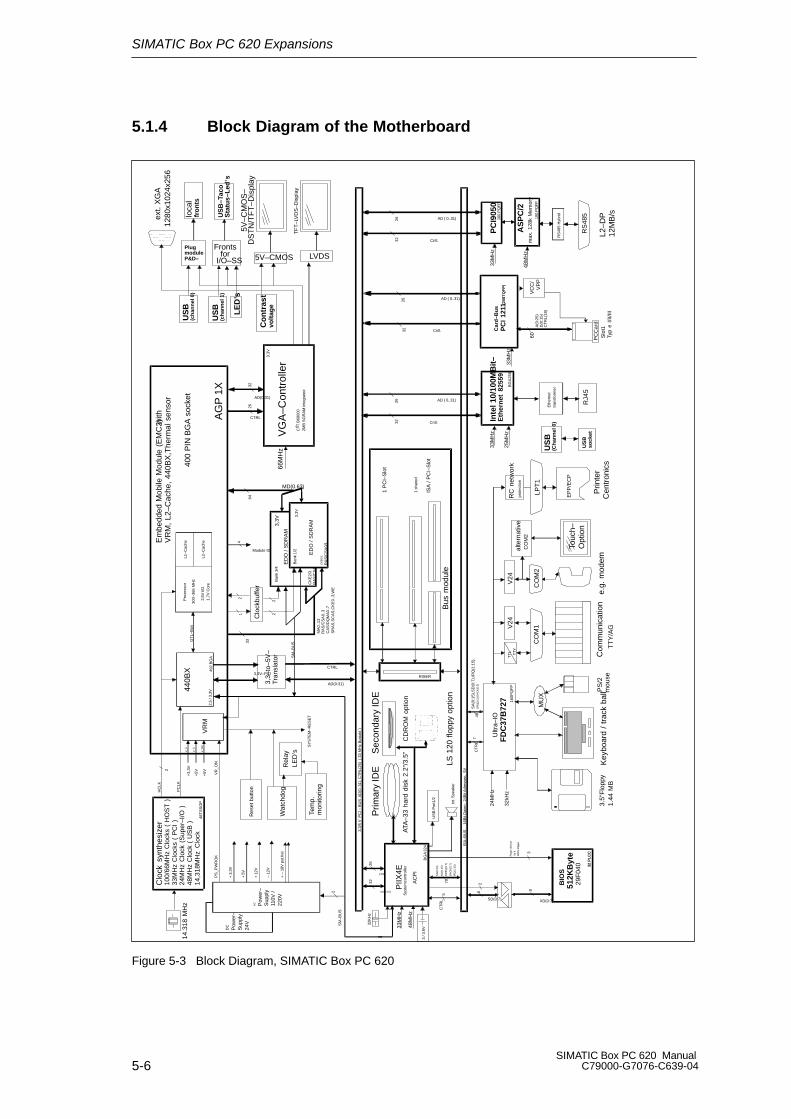
5.1.4 Block Diagram of the Motherboard
3.3/
5 V
PC
I – B
US
AD
(0..3
1), C
TR
L(26
) ( 3
3 M
Hz
Bus
takt
)
29F
040
BIO
S51
2KB
yte
ISA
–BU
S
16B
it D
aten
, 24
Bit
Adr
esse
n, 5
V
VG
A–C
ontr
olle
r
3.3V
AC Pow
er–
Sup
ply
110V
/22
0V
32 P
LC
C
PIIX
4ES
yste
mco
ntro
ller
Sec
onda
ry ID
E
CD
RO
M o
ptio
n
BG
A 32
4
32K
Hz
48M
Hz
33M
Hz
LS 1
20 f
lopp
y op
tion
AC
PI
Em
bedd
ed M
obile
Mod
ule
(EM
C2)w
ithV
RM
, L2
–Cac
he,
440B
X,T
herm
al s
enso
r
300–
366
MH
z
MD(0.63)
6433
Clo
ckbu
ffer
1
2
HC
LK
PC
LK
14.3
18 M
Hz
24M
Hz
Clo
ck (
Sup
er–I
/O )
100/
66M
Hz
Clo
cks
( H
OS
T )
33M
Hz
Clo
cks
( P
CI
)
48M
Hz
Clo
ck (
US
B )
14,3
18M
Hz
Clo
ck
Clo
ck s
ynth
esiz
er
48T
SS
OP
PS
_PW
RO
K
400
PIN
BG
A s
ocke
tG
TL–
Bus
VR
M
440B
X
2,5V
I/O
1,7V
Cor
e2,
5 / 3
,3V
492
BG
A
RA
S/C
SA
2/3
Ban
k 3/
42
2
CK
E2/
3
RA
S/C
SA
0/1
Ban
k 1/
2
ED
O /
SD
RA
M
3,3V
CK
E0/
1
CTRL
AD(0:31)
CTRL
AD(0:31)
66M
Hz
2632
VR
_ON
2
+5V
V_5
4
Module ID
2
SM
–BU
S
8 8
SD(0:7) XD(0:7)
3,3V
ED
O /
SD
RA
MS
M–B
US
5V–C
MO
S–
DS
TN
/TF
T–D
ispl
ay
TF
T–L
VD
S–D
ispl
ay
LVDS
3.5”
Flo
ppy
1.44
MB
Key
boar
d /
trac
k ba
llPS
/2m
ouse
MU
X
Com
mun
icat
ion
TT
Y/A
G
CO
M1
TT
L
TTY
Prin
ter
Cen
tron
ics
LPT
1
RC
net
wor
kpr
otec
tion
EP
P/E
CP
160P
QF
P
24M
Hz
Ultr
a–IO
FD
C37
B72
7
SA
(0:1
5),S
D(0
:7),
IRQ
(1:1
5),
DR
Q(0
:3),
DA
CK
(0:3
)48
7C
TR
L
SA
(0:2
3)
SD
(0:1
5)
DR
EQ
(0:7
)
DA
CK
(0:7
)
IRQ
(1:1
5)
3
Pag
e–S
elec
t fü
r 412
8 K
–Pag
es
CT
RL
2
570
Prim
ary
IDE
ATA
–33
hard
dis
k 2.
2”/3
.5”
US
B P
ort1
/2
MA
0..1
3R
AS
/CS
A 0.
.3C
AS
/DQ
MA
0..7
SR
AS
,SC
AS
,CK
E0.
.3,W
E
int.
Spe
aker
+ 3,
3V
C T
B69
000
2MB
SG
RA
M in
tegr
ated
AD(0:31)
32
CTRL
26
ext.
XG
A12
80x1
024x
256
VC
C/
VP
P
Cntl.
Slo
t1Ty
p e
I/II/I
II
PC
Car
d
60A
(0:2
5)D
(0:1
5)C
TR
L(18
)
AD ( 0..31)2632
33M
Hz
RS
485
L2–D
P12
MB
/s
AS
PC
/2
PC
I905
0
max
. 12
8k M
emor
y
33M
Hz
48M
Hz
100
PQ
FP
160
PQ
FP
Cntl.
AD ( 0..31)2632
RS
485
Hyb
rid
Car
d–B
us
PC
I 12
11(2
08T
QF
P)
DC Pow
er–
Sup
ply
24V
e.g.
mod
em
CO
M2
V24
I/O–SS for Fronts
Co
ntr
ast
volt
age
AG
P 1
X
LE
D’s
RJ4
5
Inte
l 10/
100M
Bit
–E
ther
net
825
5933
MH
z
BG
A25
6
Cntl.
AD ( 0..31)2632
Eth
erne
ttr
ansf
orm
er
25M
Hz
3,3–
to–5
V–
Tran
slat
or
3,3V–PCI
Bus
mod
ule
RISER
1 P
CI–
Slo
t
1 sh
ared
ISA
/ P
CI–
Slo
t
Wat
chdo
gR
elay
Tem
p.m
onito
ring
US
Bso
cket
US
B(C
han
nel
0)
P&D–modulePlug
US
B(c
han
nel
0)
5V–CMOS
US
B(c
han
nel
1)
loca
lfr
on
ts
US
B–T
aco
Sta
tus–
Led
’s
Pro
zess
or
L2–C
ache
L1–C
ache
+3,
3VV
_3
+5V
V_D
C
+ 5V
+ 12
V
– 12
V
+ –
18V
pot
.frei
SY
ST
EM
–RE
SE
T
Res
et b
utto
n
alte
rnat
ive
CO
M2
3 / 3
.6V
32kH
zV
24
Touc
h–O
ptio
n
LED
’s
Figure 5-3 Block Diagram, SIMATIC Box PC 620
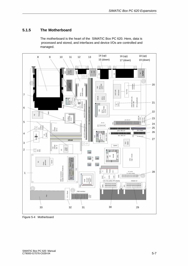
SIMATIC Box PC 620 Expansions
5-7SIMATIC Box PC 620 ManualC79000-G7076-C639-04
5.1.5 The Motherboard
The motherboard is the heart of the SIMATIC Box PC 620. Here, data is processed and stored, and interfaces and device I/Os are controlled andmanaged.
Fan
2xP
S/2
X1
– B
us c
onne
ctor
(E
ISA
slo
t)
Eth
erne
ttr
ansf
orm
er
ES
D/E
MV
LPT
1/C
OM
1,2
PIIX
AGP
MD
0/2
MD
1/3
MA
/MC
3,3V
–PC
I
DP
12 p
erip
hera
ls
DRAM
FRONT–IF
Ultr
a I/OFD
C
ISA
LPT
/C
OM
HD–SV
5V–CMOS–Display
TFT / DSTN
prim. IDE 3,5’’
sec. IDE 2,5’’
EM
C–2
pro
cess
orm
odul
e (P
entiu
m I
I/Cel
eron
)
3,3V / 5V–LVDS–TFT–Display
NB–Floppy
Eth
erne
t–C
ontr.
8255
9
E2
Qua
rz
P&D–Interface
prim. IDE 2,5’’
sec. IDE LS120
X18
(T
TY
Hyb
rid X
3133
)
D2
X12
CBT
CBT
CBT
CBT
CBT
D3
– D
7
X20 (DR
AM
slot
1)
PIIX
4E
Quartz
CP
U
US
B
IDE
ISA
PC
ID
9X
3X
4
X31
X41
D11
BIO
S
D19
X25
X6
X5
X11 X9X
805
X26
(al
t.C
OM
2)
US
B
X40
spea
ker
H1
X14
PS
U
N
7LM
77
S 2
– R
eset
X44
X42
0
X40
0
LVD
S
5V 3,3V
D11
2
CM
OS
–
Trei
ber
+E
MV
5V
D14
5–14
8
LCD
–VG
A–
Con
trol
ler
Chi
ps &
Tec
hn.
B69
000
CR
T
D15
9
X41
0,X
411
DP
12–
Hos
t–B
ridge
PLX
9050
D90
D95
,96,
D10
0–10
2,D
105–
109
X50
4
X50
3
X80
0
D15
6
Car
dbus
Con
trol
ler
PC
I121
1
TP
S22
11
N6 X
600
D14
3
Z1
X28
(fan
)X
24(C
MO
S
Bat
tery
)
VCC
Clo
ckB
uffe
r
Qua
rtz
D1
Clo
ck–
gene
rato
r
D2
X19
(DR
AM
slot
2)
DP
12–
SR
AM
D95
,96
D15
7,15
8
V24
driv
er
RJ4
5w
. LE
Ds
X17
(T
TY
Hyb
rid X
3134
)
(TT
Yak
tiv/p
assi
v)
S1
DP
12–
RS
485
mod
ule DP
12–
Con
trol
ler
AS
PC
/2
D94
othe
r
logi
c ci
rcui
ts
SM
SC
37B
727
1
2
5
4
3
8 10 11 12 13 16 (up)
17 (down)
18 (up)
19 (down)
20
21
22
23
24
26
27
28
2930313233
14 (up)
15 (down)
6
7
25
9
Figure 5-4 Motherboard

SIMATIC Box PC 620 Expansions
5-8SIMATIC Box PC 620 Manual
C79000-G7076-C639-04
Components on the Motherboard
The following components are located on the motherboard of theSIMATIC Box PC 620:
SerialNumber
Functions
1 Processor module with heat sink2 Connector for fan
3 Loudspeaker4 Connector for clock battery
5 System memory, 2 slots6 TTY transmitter *1
7 TTY receiver*1
8 PC card slots9 DIP switch TTY active/passive*1
10 RJ45 socket for ethernet LAN
11 DP12 RS485 module*1
12 MPI/DP port
13 USB bus connector14 Serial port COM 2,
15 Socket for VGA monitor16 Serial port COM 1/TTY17 Parallel port LPT 1
18 PS/2 mouse connection19 PS/2 keyboard connection20 Connection to power supply (power supply unit)
21 Temperature sensor22 Connector alternative
23 IDE connector for 3.5 “ hard disk
24 IDE connector for 2.5 “ hard disk
25 Floppy drive connector26 IDE connector for LS 120
27 IDE connector for CD-ROM28 Connector for 5 V CMOS display29 Connector for front interface
30 Connector for LVDS display (3.3 V/5 V)
31 Slot for P&D interface module
32 Button for hardware reset33 Fan
*1 Not available for the basic variant of the Box PC.
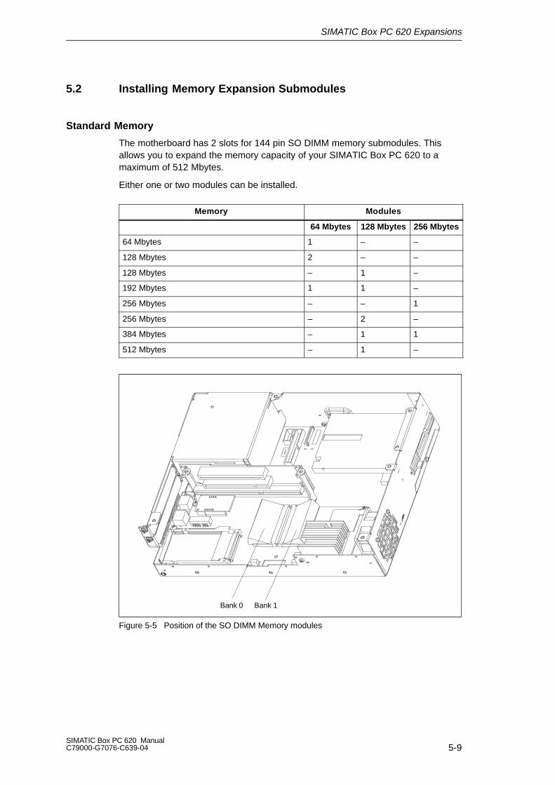
SIMATIC Box PC 620 Expansions
5-9SIMATIC Box PC 620 ManualC79000-G7076-C639-04
5.2 Installing Memory Expansion Submodules
Standard Memory
The motherboard has 2 slots for 144 pin SO DIMM memory submodules. This allows you to expand the memory capacity of your SIMATIC Box PC 620 to a maximum of 512 Mbytes.
Either one or two modules can be installed.
Memory Modules
64 Mbytes 128 Mbytes 256 Mbytes
64 Mbytes 1 – –
128 Mbytes 2 – –
128 Mbytes – 1 –
192 Mbytes 1 1 –
256 Mbytes – – 1
256 Mbytes – 2 –
384 Mbytes – 1 1
512 Mbytes – 1 –
Bank 0 Bank 1
Figure 5-5 Position of the SO DIMM Memory modules

SIMATIC Box PC 620 Expansions
5-10SIMATIC Box PC 620 Manual
C79000-G7076-C639-04
!Caution
The electronic components of the printed circuit boards are extremely sensitive toelectrostatic discharge. Certain precautionary measures are therefore necessarywhen handling such components. These measures are explained in the guidelinesfor handling electrostatically sensitive devices at the end of this manual.
Installing the SO DIMM Cards
To plug in expansion submodules, proceed as follows:
1. Open the unit as described in Section 5.1.
2. Plug the cards into the slots. Note the safety recess on the connector side ofthe SO DIMM card.
3. Push the card down applying light pressure until it locks into place.
4. Close the unit.
!Caution
Risk of damage!
Make sure that the cards sit securely in the slots, otherwise they can fall out andbe damaged.
Installation
The memory configuration is detected automatically. When you switch on the unit,the distribution of base and extended memory is displayed on the screen.

SIMATIC Box PC 620 Expansions
5-11SIMATIC Box PC 620 ManualC79000-G7076-C639-04
5.3 Replacing the Backup Battery
Battery Power Supply for Real-Time Clock and Configuration
A backup battery (3.6 V-lithium battery) powers the the real-time clock even afterthe SIMATIC Box PC 620 is switched off. In addition to the time of day, all the in-formation about the SIMATIC Box PC 620 (device configuration) is stored in RAM.If the backup battery fails or is removed, all these data are lost.
The clock uses very little power and the lithium battery has a high capacity so thatthe battery can provide backup power for the real-time clock for many years andseldom needs to be replaced.
Battery Voltage too Low
If the battery voltage is too low, the time is lost, and a correct configuration of thedevice can no longer be guaranteed.
Replacing tthe Battery
In this case, you must replace the backup battery. The battery is on the motherboard.
To change the battery, proceed as follows:
1. Switch off your SIMATIC Box PC 620 and remove the power cable and all the connecting cables.
2. Open the unit as described in Section 5.1.
3. Change the backup battery inserted in the motherboard by pulling out the connector and undoing the cable tie.
4. Secure the new battery in its mounting with a cable tie.
5. Insert the battery connector in the motherboard.
6. Close the unit.

SIMATIC Box PC 620 Expansions
5-12SIMATIC Box PC 620 Manual
C79000-G7076-C639-04
Backup battery removed
Figure 5-6 Position of the Backup Battery
!Caution
Risk of damage!
Only replace the lithium battery with an identical battery or with a typerecommended by the manufacturer (Order No.: W79084-E1003-B1).
Dispose of used batteries in keeping with local regulations.
Changing SETUP
If you change the battery or unplug the battery connector you must run the SETUPprogram to reset your programming device’s configuration data (see Chapter 6).
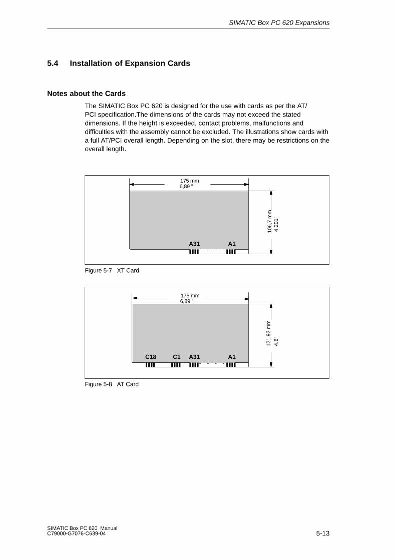
SIMATIC Box PC 620 Expansions
5-13SIMATIC Box PC 620 ManualC79000-G7076-C639-04
5.4 Installation of Expansion Cards
Notes about the Cards
The SIMATIC Box PC 620 is designed for the use with cards as per the AT/PCI specification.The dimensions of the cards may not exceed the stated dimensions. If the height is exceeded, contact problems, malfunctions and difficulties with the assembly cannot be excluded. The illustrations show cards witha full AT/PCI overall length. Depending on the slot, there may be restrictions on theoverall length.
175 mm
106,
7 m
m
A31 A1
6,89 ”
4,20
1”Figure 5-7 XT Card
121,
92 m
m
A31 A1C18 C1
4,8”
175 mm6,89 ”
Figure 5-8 AT Card

SIMATIC Box PC 620 Expansions
5-14SIMATIC Box PC 620 Manual
C79000-G7076-C639-04
174,63 mm
106,
68 m
m
8,19
mm
6,875”
0.32
2” 4,2”
Figure 5-9 Short PCI Cards (5 V)
265 mm10,48 ”
106,
68 m
m4,
2”
8,19
mm
0.32
2”
Figure 5-10 Long PCI Cards (5 V)
Note about Long PCI Cards
Before long PCI cards can be inserted into the guides of the fan trough, they mustbe fitted with a so-called extender (this should form part of the scope of supply of long PCI boards). Long PCI cards can be inserted into the guides of ISAmodules by means of this extender.
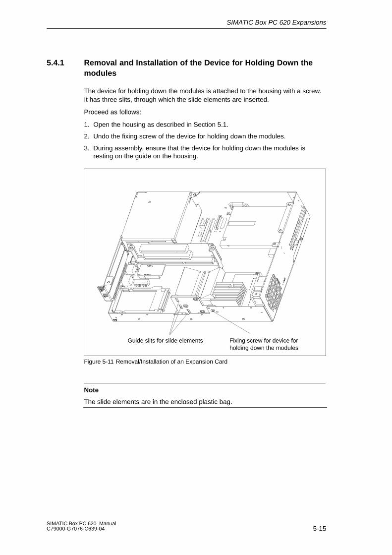
SIMATIC Box PC 620 Expansions
5-15SIMATIC Box PC 620 ManualC79000-G7076-C639-04
5.4.1 Removal and Installation of the Device for Holding Down themodules
The device for holding down the modules is attached to the housing with a screw.It has three slits, through which the slide elements are inserted.
Proceed as follows:
1. Open the housing as described in Section 5.1.
2. Undo the fixing screw of the device for holding down the modules.
3. During assembly, ensure that the device for holding down the modules is resting on the guide on the housing.
Fixing screw for device forholding down the modules
Guide slits for slide elements
Figure 5-11 Removal/Installation of an Expansion Card
Note
The slide elements are in the enclosed plastic bag.

SIMATIC Box PC 620 Expansions
5-16SIMATIC Box PC 620 Manual
C79000-G7076-C639-04
Aligning the Holding-Down Device
Proceed as follows to install the holding-down device.
1. Insert the slide element through the guide slit until it is resting firmly on the module. The module must now be introduced into the notch.
!Caution
No pressure may be exerted on the module! Therefore, do not use force to pressthe slide element onto the module.
2. Cut off the projecting part of the slide element:
– Score the slide element at the top edge of the holding-down device with aknife and break it off.
– Nip off the surplus with a sharp side cutter.
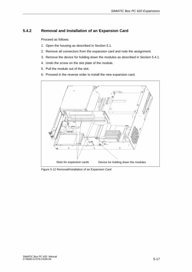
SIMATIC Box PC 620 Expansions
5-17SIMATIC Box PC 620 ManualC79000-G7076-C639-04
5.4.2 Removal and Installation of an Expansion Card
Proceed as follows:
1. Open the housing as described in Section 5.1.
2. Remove all connectors from the expansion card and note the assignment.
3. Remove the device for holding down the modules as described in Section 5.4.1.
4. Undo the screw on the slot plate of the module.
5. Pull the module out of the slot.
6. Proceed in the reverse order to install the new expansion card.
Slots for expansion cards Device for holding down the modules
Figure 5-12 Removal/Installation of an Expansion Card

SIMATIC Box PC 620 Expansions
5-18SIMATIC Box PC 620 Manual
C79000-G7076-C639-04
5.5 Removal and Installation of Drives
5.5.1 Removal and Installation of the Hard Disk Drive
1. Undo the 4 screws on the back of the housing.
2. Open the drive holder.
3. Detach the drive holder from the mounting and lay the drive holder with its topon the housing.
4. Note the cable assignment and pull off the cables.
5. Undo the four screws which secure the hard disk drive to the vibration-dampedpart of the mounting. Remove the hard disk drive from the mounting.
6. Proceed in the reverse order to fit the new drive. The new drive must be of thesame type as the one removed.
Fixing screws
Figure 5-13 Installation and Removal of the Drive Holder
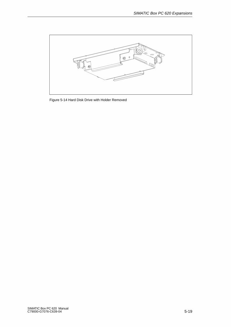
SIMATIC Box PC 620 Expansions
5-19SIMATIC Box PC 620 ManualC79000-G7076-C639-04
Figure 5-14 Hard Disk Drive with Holder Removed
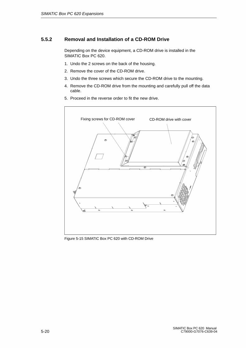
SIMATIC Box PC 620 Expansions
5-20SIMATIC Box PC 620 Manual
C79000-G7076-C639-04
5.5.2 Removal and Installation of a CD-ROM Drive
Depending on the device equipment, a CD-ROM drive is installed in theSIMATIC Box PC 620.
1. Undo the 2 screws on the back of the housing.
2. Remove the cover of the CD-ROM drive.
3. Undo the three screws which secure the CD-ROM drive to the mounting.
4. Remove the CD-ROM drive from the mounting and carefully pull off the datacable.
5. Proceed in the reverse order to fit the new drive.
CD-ROM drive with coverFixing screws for CD-ROM cover
Figure 5-15 SIMATIC Box PC 620 with CD-ROM Drive
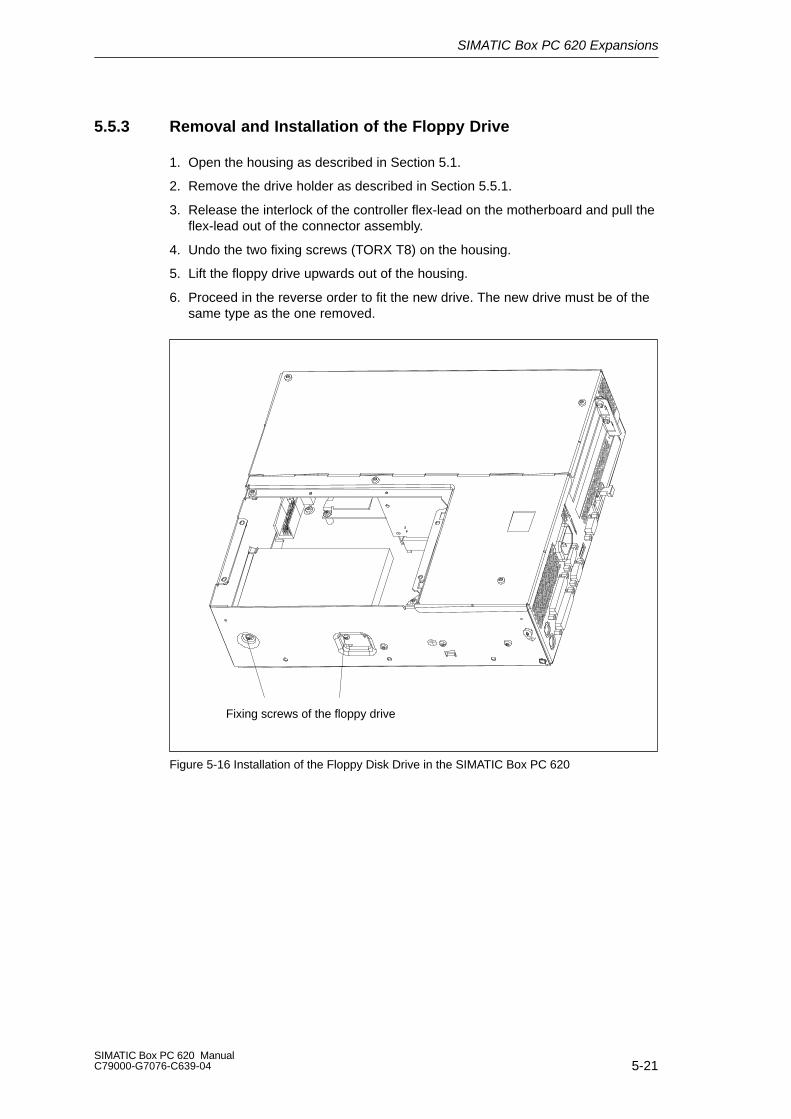
SIMATIC Box PC 620 Expansions
5-21SIMATIC Box PC 620 ManualC79000-G7076-C639-04
5.5.3 Removal and Installation of the Floppy Drive
1. Open the housing as described in Section 5.1.
2. Remove the drive holder as described in Section 5.5.1.
3. Release the interlock of the controller flex-lead on the motherboard and pull theflex-lead out of the connector assembly.
4. Undo the two fixing screws (TORX T8) on the housing.
5. Lift the floppy drive upwards out of the housing.
6. Proceed in the reverse order to fit the new drive. The new drive must be of thesame type as the one removed.
Fixing screws of the floppy drive
Figure 5-16 Installation of the Floppy Disk Drive in the SIMATIC Box PC 620

SIMATIC Box PC 620 Expansions
5-22SIMATIC Box PC 620 Manual
C79000-G7076-C639-04
5.5.4 Removal and Installation of the LS 120 Drive
The removal and installation of the LS120 drive takes place with the same steps asfor the floppy drive.
1. Open the housing as described in Section 5.1.
2. Remove the drive holder as described in Section 5.5.1.
3. Release the cable clamp assembly of the controller flex-lead on the motherboard and pull the flex-lead out of the connector assembly.
4. Undo the two fixing screws (TORX T8) on the housing.
5. Lift the LS 120 drive upwards out of the housing.
6. Proceed in the reverse order to fit the new drive.
Fixing screws of the LS 120 drive
Screw for LS 120 cable clamp assembly
Figure 5-17 Installation of the LS 120 Drive
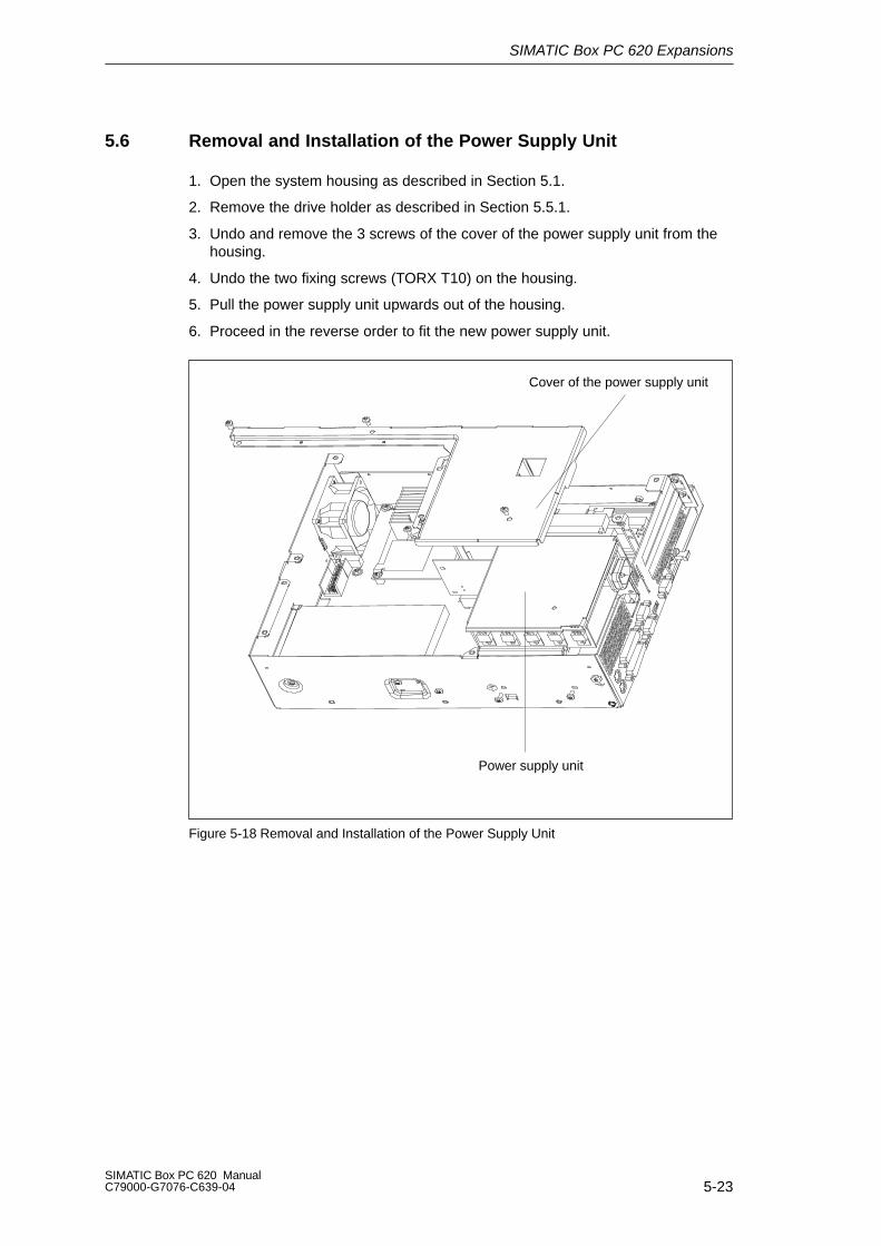
SIMATIC Box PC 620 Expansions
5-23SIMATIC Box PC 620 ManualC79000-G7076-C639-04
5.6 Removal and Installation of the Power Supply Unit
1. Open the system housing as described in Section 5.1.
2. Remove the drive holder as described in Section 5.5.1.
3. Undo and remove the 3 screws of the cover of the power supply unit from thehousing.
4. Undo the two fixing screws (TORX T10) on the housing.
5. Pull the power supply unit upwards out of the housing.
6. Proceed in the reverse order to fit the new power supply unit.
Power supply unit
Cover of the power supply unit
Figure 5-18 Removal and Installation of the Power Supply Unit
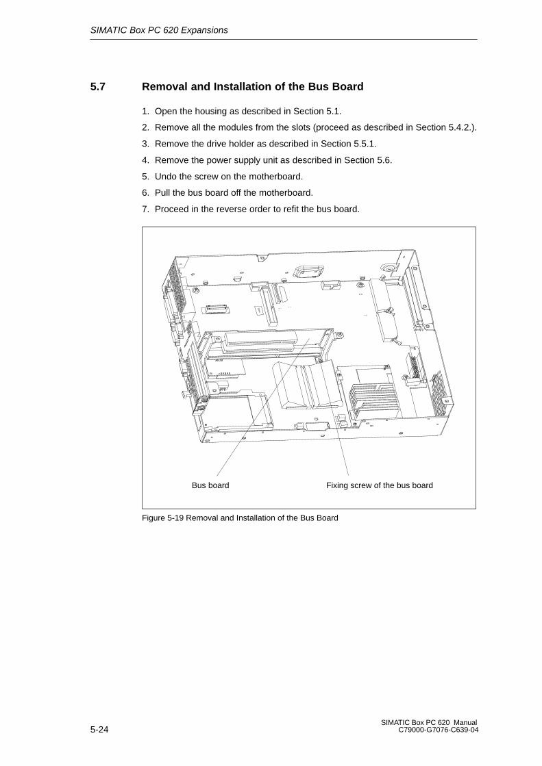
SIMATIC Box PC 620 Expansions
5-24SIMATIC Box PC 620 Manual
C79000-G7076-C639-04
5.7 Removal and Installation of the Bus Board
1. Open the housing as described in Section 5.1.
2. Remove all the modules from the slots (proceed as described in Section 5.4.2.).
3. Remove the drive holder as described in Section 5.5.1.
4. Remove the power supply unit as described in Section 5.6.
5. Undo the screw on the motherboard.
6. Pull the bus board off the motherboard.
7. Proceed in the reverse order to refit the bus board.
Bus board Fixing screw of the bus board
Figure 5-19 Removal and Installation of the Bus Board
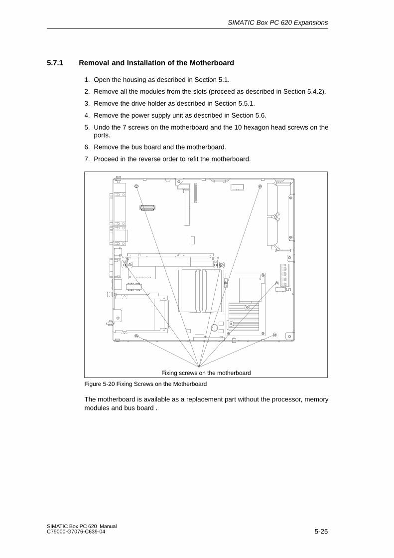
SIMATIC Box PC 620 Expansions
5-25SIMATIC Box PC 620 ManualC79000-G7076-C639-04
5.7.1 Removal and Installation of the Motherboard
1. Open the housing as described in Section 5.1.
2. Remove all the modules from the slots (proceed as described in Section 5.4.2).
3. Remove the drive holder as described in Section 5.5.1.
4. Remove the power supply unit as described in Section 5.6.
5. Undo the 7 screws on the motherboard and the 10 hexagon head screws on theports.
6. Remove the bus board and the motherboard.
7. Proceed in the reverse order to refit the motherboard.
Fixing screws on the motherboard
Figure 5-20 Fixing Screws on the Motherboard
The motherboard is available as a replacement part without the processor, memorymodules and bus board .

SIMATIC Box PC 620 Expansions
5-26SIMATIC Box PC 620 Manual
C79000-G7076-C639-04
5.8 Removal and Installation of the Fan
The SIMATIC Box PC 620 is cooled by means of a fan which sucks hot air out ofthe housing.
1. Open the housing as described in Section 5.1.
2. Pull off the fan cable connector on the basic board.
3. The fan is secured to the housing by two plastic rivets. Undo the rivets bypressing out the gudgeon from the rear of the rivet shank.
4. Remove the fan.
5. Proceed in the reverse order for assembly.
Fan Plastic rivets
Figure 5-21 Removal and Installation of the Fan
Note
Only a fan of the same type may be fitted!
!CautionTo ensure that the device is adequately cooled, take care that the running directionof the fan is correct when installing.
Ensure that the arrow on the fan points to the housing wall.
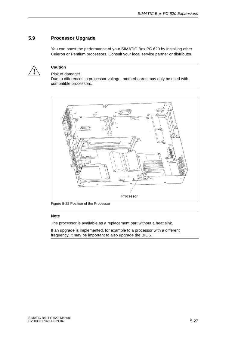
SIMATIC Box PC 620 Expansions
5-27SIMATIC Box PC 620 ManualC79000-G7076-C639-04
5.9 Processor Upgrade
You can boost the performance of your SIMATIC Box PC 620 by installing otherCeleron or Pentium processors. Consult your local service partner or distributor.
!Caution
Risk of damage!Due to differences in processor voltage, motherboards may only be used withcompatible processors.
Processor
Figure 5-22 Position of the Processor
Note
The processor is available as a replacement part without a heat sink.
If an upgrade is implemented, for example to a processor with a differentfrequency, it may be important to also upgrade the BIOS.
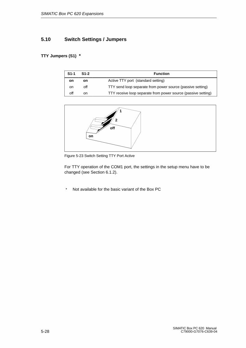
SIMATIC Box PC 620 Expansions
5-28SIMATIC Box PC 620 Manual
C79000-G7076-C639-04
5.10 Switch Settings / Jumpers
TTY Jumpers (S1) *
S1-1 S1-2 Function
on on Active TTY port (standard setting)
on off TTY send loop separate from power source (passive setting)
off on TTY receive loop separate from power source (passive setting)
on
off
1
2
Figure 5-23 Switch Setting TTY Port Active
For TTY operation of the COM1 port, the settings in the setup menu have to bechanged (see Section 6.1.2).
* Not available for the basic variant of the Box PC
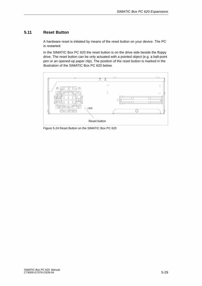
SIMATIC Box PC 620 Expansions
5-29SIMATIC Box PC 620 ManualC79000-G7076-C639-04
5.11 Reset Button
A hardware reset is initiated by means of the reset button on your device. The PCis restarted.
In the SIMATIC Box PC 620 the reset button is on the drive side beside the floppydrive. The reset button can be only actuated with a pointed object (e.g. a ball-pointpen or an opened-up paper clip). The position of the reset button is marked in theillustration of the SIMATIC Box PC 620 below.
Reset button
Figure 5-24 Reset Button on the SIMATIC Box PC 620

SIMATIC Box PC 620 Expansions
5-30SIMATIC Box PC 620 Manual
C79000-G7076-C639-04

6-1SIMATIC Box PC 620 ManualC79000-G7076-C639-04
Configuring the SIMATIC Box PC 620
What Does This Chapter Contain?
In this chapter, you will learn how to configure your programming device. You needto do this if you change your system by adding, removing, or exchanging expansion modules and memory expansions, or by replacing a system module.
Chapter Overview
In chapter you will find on page
6.1 Changing the Device Configuration with SETUP 6-2
6.1.1 The Main Menu 6-5
6.1.2 The Advanced Menu 6-15
6.1.3 The Security Menu 6-22
6.1.4 The Power Menu 6-24
6.1.5 The Boot Sequence Menu 6-26
6.1.6 The Version Menu 6-28
6.1.7 The Exit Menu 6-29
6.1.8 Default Setup Settings 6-30
6.2 Configuring the PCMCIA Interface 6-33
6
Configuring the SIMATIC Box PC 620
6-2SIMATIC Box PC 620 Manual
C79000-G7076-C639-04
6.1 Changing the Device Configuration with SETUP
Changing the Device Configuration
Your SIMATIC Box PC 620 device configuration is set for working with the softwaresupplied with the unit. You should only change the preset values if you havemodified your Box PC in any way or if a fault occurs when the unit is powered up.
SETUP Program
The SETUP program is in the ROM-BIOS. Information about the system configuration is stored in the battery-backed RAM of the SIMATIC Box PC 620.
You can use SETUP to set the hardware configuration (for example, hard disktype) and define the system characteristics. You can also use SETUP to set thetime of day and date.
Incorrect SETUP Data
If incorrect SETUP data are detected when you boot the system, the BIOSprompts you to
Start SETUP by pressing F2 or
Continue booting by pressing F1.
Starting SETUP
On completion of the startup test, the BIOS gives you the opportunity of startingthe SETUP program by displaying the following screen prompt:
PRESS < F2 > to enter SETUP
To start SETUP, proceed as follows:
1. Reset your PG 720 (warm or cold restart).
2. Press the F2 key as long as the BIOS prompt appears on the screen.
SETUP Menus
The various menus and submenus are listed on the following pages. You can getall the information you need for the SETUP entry selected from the“Item Specific Help” part of the relevant menu.

Configuring the SIMATIC Box PC 620
6-3SIMATIC Box PC 620 ManualC79000-G7076-C639-04
Screen Display Following Power On
With the default setting of your PC, the display shown below appears followingpower-on:
Phoenix BIOS 4.0 A5E00016562–ES04
Copyright 1985-98 Phoenix Technologies Ltd.
All Rights Reserved.
SIMATIC Box PC 620 V07.01.04
CPU = PentiumII 266MHz640K System RAM Passed
63MB Extended RAM Passed
0128K Cache SRAM Passed
System BIOS shadowed
Video BIOS shadowedUMB upper limit segment address: xxxx
Mouse initialized
Fixed Disk 0: xxxx
ATAPI CD-ROM: Txxx
Press <F2> to enter SETUP
If you press the F2 key while the above display is shown, you select theROM-based BIOS setup program. In this program, you can set a number of system functions and hardware configurations of your programming device.
The default settings are effective on delivery. You can change these settings usingthe BIOS setup. The modified settings become effective when you have saved them and terminated the BIOS setup.
The following screen shots may differ from what is shown here, depending on thedevice configuration. The following screen form appears when you start the BIOSsetup:
PhoenixBIOS Setup Utility
Item Specific HelpSystem Time:
ESC Exit
TabSystem Date:[ 15:35:32 ]
Select Item
Select Menu
+ / –
Enter Select
Change Values
Sub-Menu
F9
F10
Setup Defaults
Save and Exit
Shift-Tab Enter, orselects field.
Diskette A: [ 1.44 MB, 31/2” ]Primary Master [4326 MB]Primary Slave [None]
Memory Cache:Boot OptionsKeyboard Features
[Write Back]
Hardware Options
System Memory:Extended Memory:
Main Security Power ExitMenu bar
Operation line
Help window
Selectablesubmenu
Advanced
Secondary Master [None]Secondary Slave [None]
[ 01/23/1999 ]
640 KB64512 KB
Header
Example:Hour/Minute/SecondMonth/Day/Year
Boot Sequence Version
F1 Help
Figure 6-1 SETUP Main Menu
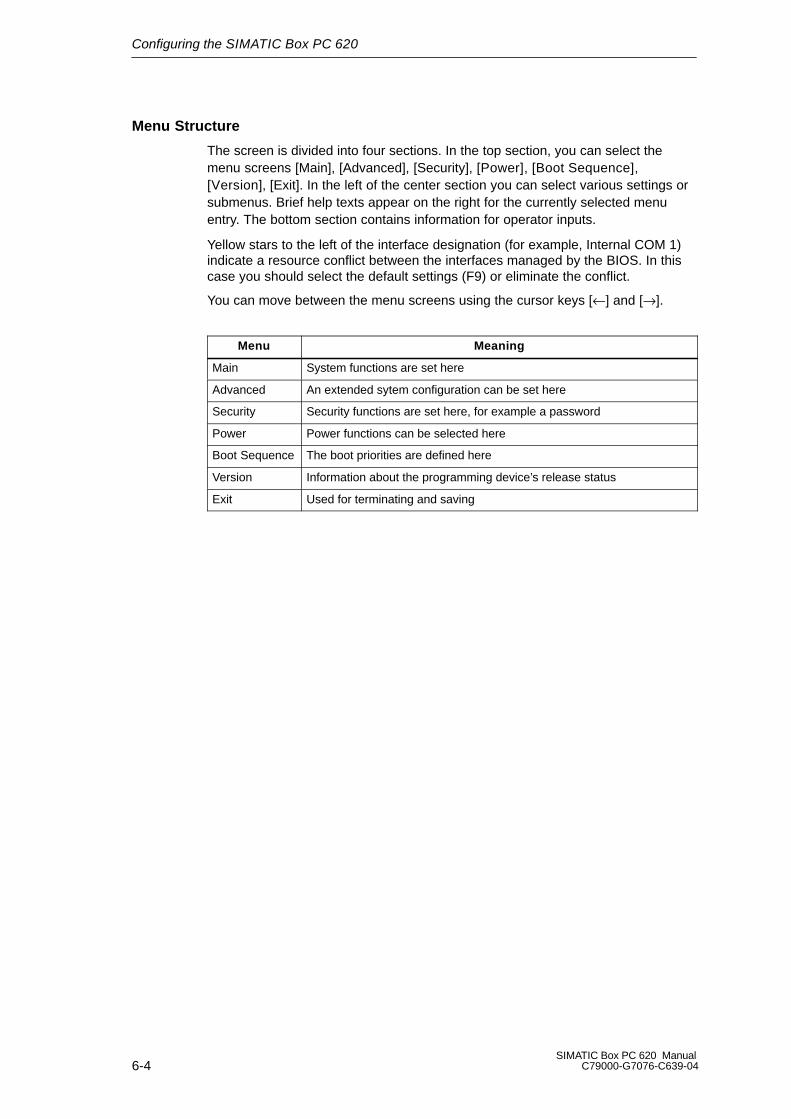
Configuring the SIMATIC Box PC 620
6-4SIMATIC Box PC 620 Manual
C79000-G7076-C639-04
Menu Structure
The screen is divided into four sections. In the top section, you can select themenu screens [Main], [Advanced], [Security], [Power], [Boot Sequence],[Version], [Exit]. In the left of the center section you can select various settings orsubmenus. Brief help texts appear on the right for the currently selected menuentry. The bottom section contains information for operator inputs.
Yellow stars to the left of the interface designation (for example, Internal COM 1)indicate a resource conflict between the interfaces managed by the BIOS. In thiscase you should select the default settings (F9) or eliminate the conflict.
You can move between the menu screens using the cursor keys [←] and [→].
Menu Meaning
Main System functions are set here
Advanced An extended sytem configuration can be set here
Security Security functions are set here, for example a password
Power Power functions can be selected here
Boot Sequence The boot priorities are defined here
Version Information about the programming device’s release status
Exit Used for terminating and saving
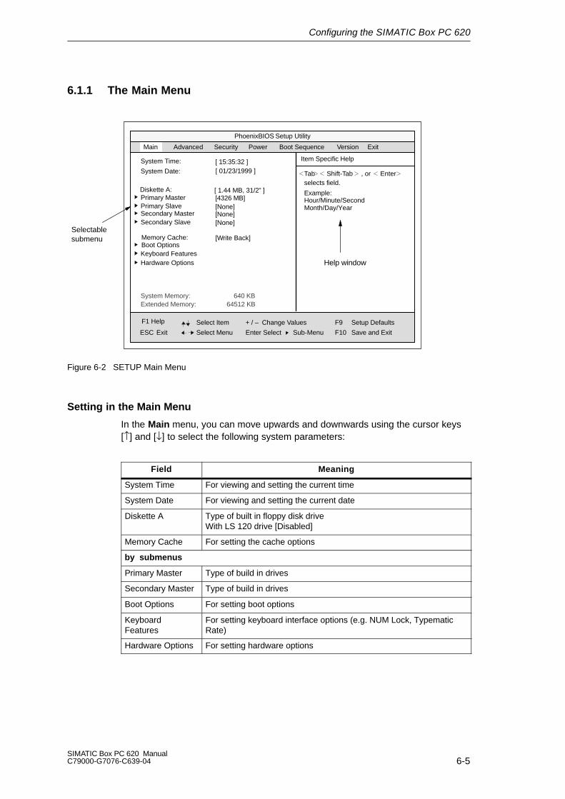
Configuring the SIMATIC Box PC 620
6-5SIMATIC Box PC 620 ManualC79000-G7076-C639-04
6.1.1 The Main Menu
PhoenixBIOS Setup Utility
Item Specific HelpSystem Time:
ESC Exit
TabSystem Date:[ 15:35:32 ]
Select Item
Select Menu
+ / –
Enter Select
Change Values
Sub-Menu
F9
F10
Setup Defaults
Save and Exit
Shift-Tab Enter, orselects field.
Diskette A: [ 1.44 MB, 31/2” ]Primary Master [4326 MB]Primary Slave [None]
Memory Cache:Boot OptionsKeyboard Features
[Write Back]
Hardware Options
System Memory:Extended Memory:
Main Security Power Exit
Help window
Selectablesubmenu
Advanced
Secondary Master [None]Secondary Slave [None]
[ 01/23/1999 ]
640 KB64512 KB
Example:Hour/Minute/SecondMonth/Day/Year
Boot Sequence Version
F1 Help
Figure 6-2 SETUP Main Menu
Setting in the Main Menu
In the Main menu, you can move upwards and downwards using the cursor keys[↑] and [↓] to select the following system parameters:
Field Meaning
System Time For viewing and setting the current time
System Date For viewing and setting the current date
Diskette A Type of built in floppy disk driveWith LS 120 drive [Disabled]
Memory Cache For setting the cache options
by submenus
Primary Master Type of build in drives
Secondary Master Type of build in drives
Boot Options For setting boot options
KeyboardFeatures
For setting keyboard interface options (e.g. NUM Lock, TypematicRate)
Hardware Options For setting hardware options
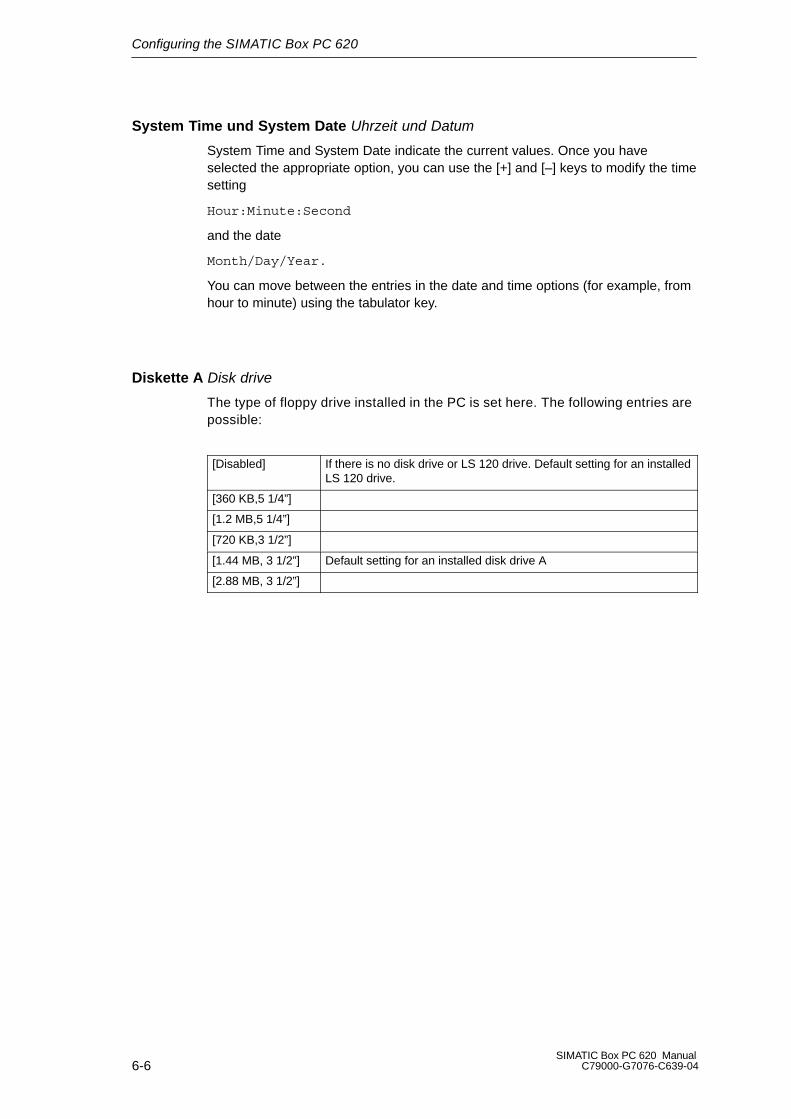
Configuring the SIMATIC Box PC 620
6-6SIMATIC Box PC 620 Manual
C79000-G7076-C639-04
System Time und System Date Uhrzeit und Datum
System Time and System Date indicate the current values. Once you have selected the appropriate option, you can use the [+] and [–] keys to modify the timesetting
Hour:Minute:Second
and the date
Month/Day/Year.
You can move between the entries in the date and time options (for example, fromhour to minute) using the tabulator key.
Diskette A Disk drive
The type of floppy drive installed in the PC is set here. The following entries arepossible:
[Disabled] If there is no disk drive or LS 120 drive. Default setting for an installedLS 120 drive.
[360 KB,5 1/4”]
[1.2 MB,5 1/4”]
[720 KB,3 1/2”]
[1.44 MB, 3 1/2”] Default setting for an installed disk drive A
[2.88 MB, 3 1/2”]

Configuring the SIMATIC Box PC 620
6-7SIMATIC Box PC 620 ManualC79000-G7076-C639-04
Primary Master Primary Slave Secondary Master/ Secondary Slave
The system jumps to the following submenu when you select this type of menufield:
PhoenixBIOS Setup Utility
Item Specific Help
ESC Exit
Select Item
Select Menu
+ / –
Enter Select
Change Values F9
F10
Setup Defaults
Save and ExitSub-Menu
Type:Cylinders:
[Auto]
Heads:Total SectorsMaximum Capacity
Main
Primary Master [4326MB]
Multi-Sector Transfers:LBA Mode Control:32 Bit I/O:Transfer Mode:
[8940][ 15][8448300]4326MB
[16 Sectors][Enabled][Enabled][FPIO 4 / DMA 2]
Ultra DMA Mode: [Disabled]
[AUTO] (recommended)Autotypes installed IDE-devices
[USER]Enter parameters of IDE-devices installed at this connection
F1 Help
Figure 6-3 Primary Master
“Type” Field
The parameters you can select here are usually stored on the IDE drive. The ’Auto’setting in the ’Type’ field means that these values are automatically read from thedrive and written into memory (Autodetect).
If Type is selected for a drive that cannot be detected, a timer times out in approximately 1 minute and the entries remain unchanged. You should alwayscheck that the interfaces for which you select ’Auto’ are in fact connected to drives.
Select “User” if you want to define the hard-disk type yourself, in which case remember that you also have to set the other fields, including Cylinder, Heads,Sectors/Track and WritePrecomp, to the correct values for the type of hard disk inquestion.

Configuring the SIMATIC Box PC 620
6-8SIMATIC Box PC 620 Manual
C79000-G7076-C639-04
“Multi Sector-Transfer” Field
The entry in the Multi-Sector Transfer field defines the number of sectors transferred per interrupt. The value depends on the drive and should be set only bysetting the Type field to Auto.
Disabled
2,4,8,16 sectors
“LBA Mode Control” field
If the LBA Mode Control field (enabled,disabled) is set to ’Enabled’, the systemsupports hard disks with capacities greater than 528 Mbytes. The value dependson the drive and should be set only by setting the Type field to Auto.
“32 Bit-IO” Field
The setting in the 32 Bit I/O field defines the mode of access for the drive
Disabled 16-Bit access
Enabled 32-Bit access (default)
“Transfer Mode” and “Ultra DMA Mode” Fields
The settings in these fields define the interface’s data-transfer rate. The valuedepends on the drive and should be set only by setting the Type field to Auto.
Hit ESC to exit the submenu.
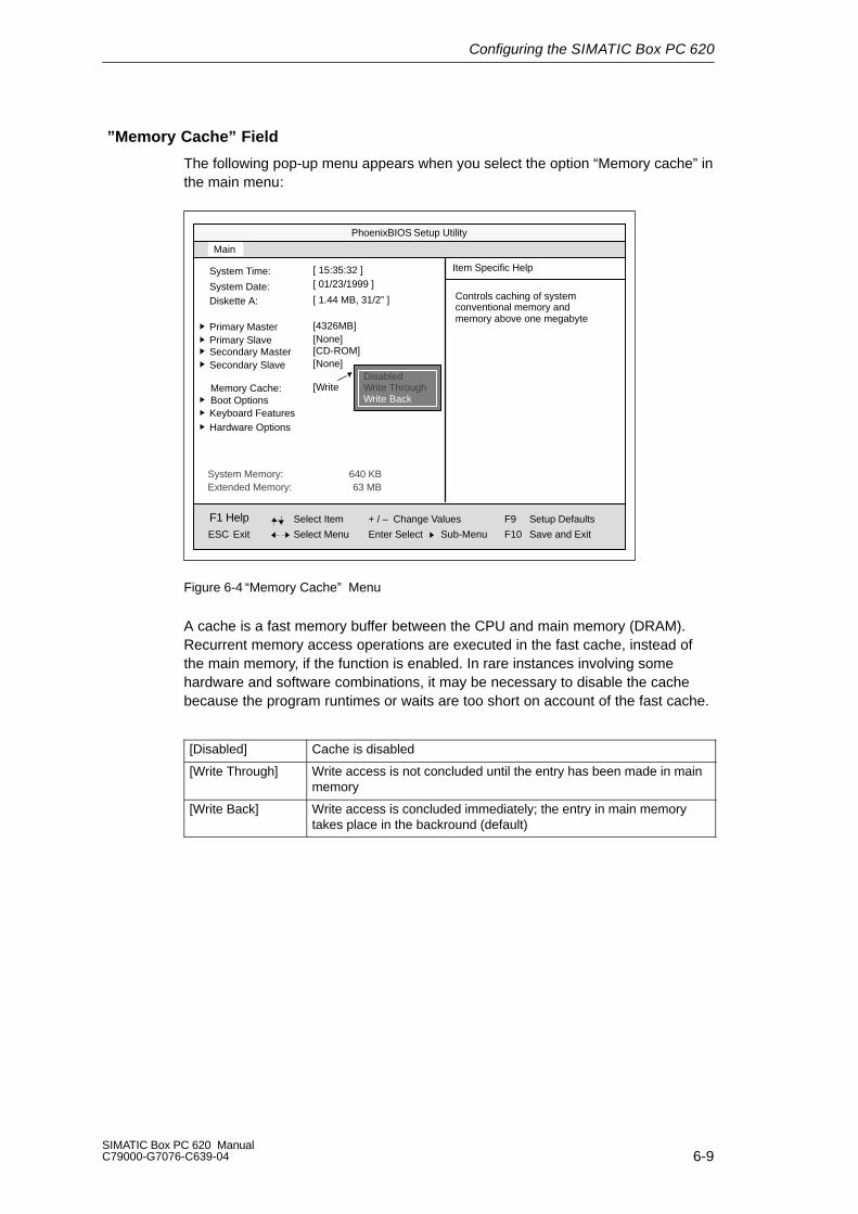
Configuring the SIMATIC Box PC 620
6-9SIMATIC Box PC 620 ManualC79000-G7076-C639-04
”Memory Cache” Field
The following pop-up menu appears when you select the option “Memory cache” inthe main menu:
PhoenixBIOS Setup Utility
Item Specific HelpSystem Time:
ESC Exit
System Date:
[ 15:35:32 ]
Select Item
Select Menu
+ / –
Enter Select
Change Values
Sub-Menu
F9
F10
Setup Defaults
Save and Exit
Diskette A: [ 1.44 MB, 31/2” ]
Primary Master [4326MB]Primary Slave [None]
Memory Cache:Boot OptionsKeyboard Features
[Write
Hardware Options
System Memory:Extended Memory:
Main
Secondary Master [CD-ROM]Secondary Slave [None]
[ 01/23/1999 ]
640 KB63 MB
Controls caching of systemconventional memory andmemory above one megabyte
DisabledWrite ThroughWrite Back
F1 Help
Figure 6-4 “Memory Cache” Menu
A cache is a fast memory buffer between the CPU and main memory (DRAM). Recurrent memory access operations are executed in the fast cache, instead ofthe main memory, if the function is enabled. In rare instances involving some hardware and software combinations, it may be necessary to disable the cache because the program runtimes or waits are too short on account of the fast cache.
[Disabled] Cache is disabled
[Write Through] Write access is not concluded until the entry has been made in mainmemory
[Write Back] Write access is concluded immediately; the entry in main memorytakes place in the backround (default)

Configuring the SIMATIC Box PC 620
6-10SIMATIC Box PC 620 Manual
C79000-G7076-C639-04
Option ”Boot Options”
The following submenu appears when you select the option “Boot Options” in themain menu:
PhoenixBIOS Setup-Utility
Item Specific Help
ESC Exit
Select Item
Select Menu
+ / –
Enter Select
Change Values F9
F10
Setup Defaults
Save and ExitSub-Menu
QuickBoot Mode:
SETUP prompt: [Enabled]
Main
Boot Options
[Enabled] Allows the system to skip cer-tain tests while booting. Thiswill decrease the time neededto boot the system.
POST Errors: [Enabled]
Floppy check: [Disabled]
Summary screen: [Enabled]
F1 Help
Figure 6-5 ”Boot Options”Submenu
Quick BootMode
Some hardware tests are skipped to speed up the boot procedure.
SETUP prompt The message PRESS <F2> to enter Setup appears at the bottom of thescreen during the system run-up phase.
POST Errors The boot process is stopped if an error is detected; you must press F1 toacknowledge. Enter “Disabled”to avoid the necessity of acknowledgingerrors, for example if no keyboard is connected.

Configuring the SIMATIC Box PC 620
6-11SIMATIC Box PC 620 ManualC79000-G7076-C639-04
Floppy check The floppy head is stepped inward and then back to its original positionduring the system run-up phase. This test is useful because it reinitializes the drive.
Summaryscreen
The most important system parameters are displayed when the systemrun-up phase completes.
’Enabled’ means that the feature is active. ’Disabled’ means that the feature is inactive.
Example of a summary screen:
PhoenixBIOS Set Up Utility
CPU:CPU Speed 266 MHz
System 640 KBExtended 63 MBShadow RAM: 384 KBCache RAM: 512 kB
Hard Disk 0: 6495 MBHard Disk 1: None
System ROM:BIOS Date: 03/06/97
Fxx – FFFF
COM Ports: 03F8, 02F8LPT Ports: 0378Display Type: VGAPS/2 Mouse: Installed
Diskette A: 1,44 MB, 31/2 ”
SIMATIC Box PC 620 BIOS Version: V7....
Pentium PII
Hard Disk 2:Hard Disk 3: None
Figure 6-6 Summary Screen
The Summary screen appears when the system run-up phase completes.
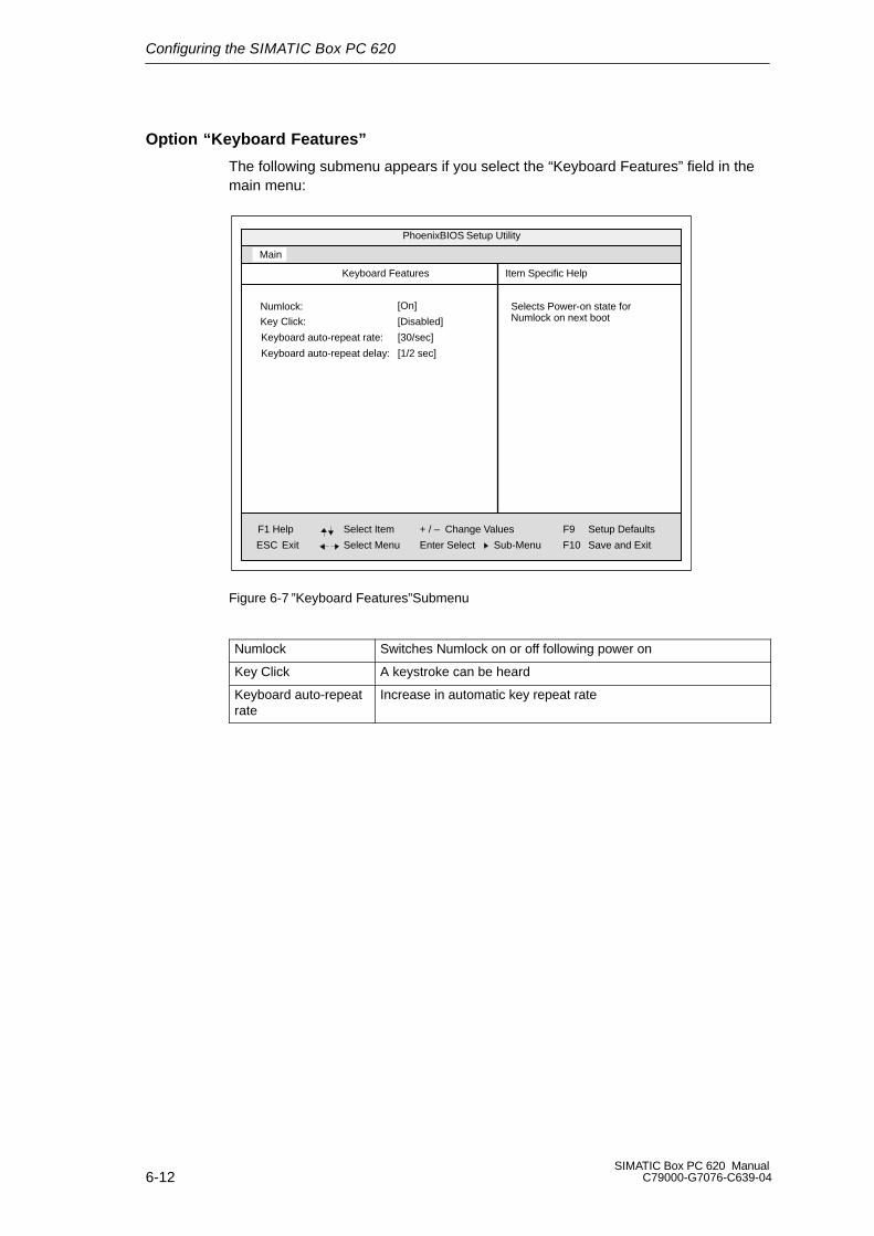
Configuring the SIMATIC Box PC 620
6-12SIMATIC Box PC 620 Manual
C79000-G7076-C639-04
Option “Keyboard Features”
The following submenu appears if you select the “Keyboard Features” field in themain menu:
PhoenixBIOS Setup Utility
Item Specific Help
ESC Exit
Select Item
Select Menu
+ / –
Enter Select
Change Values F9
F10
Setup Defaults
Save and ExitSub-Menu
Numlock:
Key Click: [Disabled]
Main
Keyboard Features
[On] Selects Power-on state forNumlock on next boot
Keyboard auto-repeat rate: [30/sec]
Keyboard auto-repeat delay: [1/2 sec]
F1 Help
Figure 6-7 ”Keyboard Features”Submenu
Numlock Switches Numlock on or off following power on
Key Click A keystroke can be heard
Keyboard auto-repeatrate
Increase in automatic key repeat rate

Configuring the SIMATIC Box PC 620
6-13SIMATIC Box PC 620 ManualC79000-G7076-C639-04
”Hardware Options” Field
The following submenu appears when you select the “Hardware Options” field inthe main menu:
PhoenixBIOS Setup-Utility
Item Specific Help
ESC Exit
Select Item
Select Menu
+ / –
Enter Select
Change Values F9
F10
Setup Defaults
Save and ExitSub-Menu
PCI - MPI / DP:
Main
Hardware Options
[Enabled]Enable or disable the PCI - Multi Point Interface (MPI / DP)
Trackball / PS/2 Mouse:: [Auto]
CRT / LCD selection: [SIMULTAN]CRT 640 X 480: [75 Hz]CRT 800 X 600: [75 Hz]CRT 1024 X 768: [75 Hz]LCD-Screensize: [Graph& Text Expand]
Cardbus/PCMCIA Slot: [Enabled]
F1 Help
Ethernet Adress: [080006247000]
SafeCard functions: [Enabled]Legacy USB Suport: [Disabled]
On Board Ethernet [Enabled]
DSTN Contrast: [154]
Figure 6-8 ”Hardware Options” Submenu
The parameters of the interfaces present on the basic module are set here.
Entry Meaning
PCI-MPI/DP *1 Enables the CP5611-compatible MPI/DP interface. The recourses aremanaged by the BIOS PCI plug and play mechanism.
On BoardEthernet
[Enabled] The ethernet port on the motherboard is enabled.
[Disabled] The ethernet port on the motherboard is disabled.
Ethernet Address
The individual ethernet address is entered here.
Cardbus /PCMCIA Slot
[Disabled] Disables the Cardbus / PCMCIA interfaces.
[Enabled] The resources are managed by the BIOSPCI plug and play mechanism.
SafeCardfunctions
[Enabled] On board monitoring functions are enabled.
[Disabled] No monitoring functions.
The relevant driver and the application must be started for operation ofthe monitoring functions.
Legacy USBSuport
[Disabled] A USB-capable operating system is required to operate a USB keyboard or a USB mouse. Setup adjustments can be made with a USB keyboard.
[Enabled] USB keyboard and USB mouse are supported by theBIOS. Non-USB capable operating systems can beused.

Configuring the SIMATIC Box PC 620
6-14SIMATIC Box PC 620 Manual
C79000-G7076-C639-04
Entry Meaning
CRT / LCDselection
[LCD Enabled] All data is output only to the internal LCD, the 15-way VGA port is disabled
[CRT Enabled] For maximum resolution the display signals are output only to the 15-way VGA port; the LCD interface of the VGA controller is disabled.
[SIMULTAN] Both display interfaces are enabled and operate simultaneously. Note, however, that the LCD does notsupport all resolutions.
CRT 640 x 480 Refresh rate with a resolution of 640x480 pixels
CRT 800 x 600 Refresh rate with a resolution of 800x600 pixels
CRT 1024 x768
Refresh rate with a resolution of 1024x768 pixels
LCD-Screen-size
[Normal] The display window in Text and Graphic modes is not expanded to full screen size.
[Text expand] Only the Text modes are expanded to full screen size.
[Graph&Text expand] The Graphic and Text modes are expanded to full screen size.
DSTN Contrast The contrast of the DSTN displays is set here. Range: 0-255
Trackball / PS/2 Mouse
[Internal] The PS/2 port is activated. This is the default for the SIMATIC Box PC 620, the trackball is activated in this setting. IRQ 12 is assigned.
[External] The PS/2 port is activated, IRQ12 is assigned. The keyboard trackball is disabled, an external PS/2
mouse must be connected. If no external mouse is connected when the system boots, the BIOS deactivates the PS/2 port.
[AUTO] Automatic detection of the type of mouse connected. A PS/2 mouse takes priority over the keyboard trackball
[Disabled] The PS/2 port is deactivated, IRQ12 is available.
Note: Invariably, changes to this interface do not come into effect until the PC is switched off and on again.
*1 Not available for the basic variant of the Box PC

Configuring the SIMATIC Box PC 620
6-15SIMATIC Box PC 620 ManualC79000-G7076-C639-04
6.1.2 The Advanced Menu
Menu Structure
PhoenixBIOS Setup-Utility
Item Specific Help
ESC Exit
Select Item
Select Menu
+ / –
Enter Select
Change Values F9
F10
Setup Defaults
Save and ExitSub-Menu
Main Security PowerAdvanced
Installed O/S: [Other]Reset Configuration Data: [No]
Local Bus IDE adapter:Floppy disk controller: [Enabled]
[Primary & Secondary]Large Disk Access Mode: [DOS]
Memory Gap at 15 Mbyte: [Disabled]
COM / LPT ConfigurationPCI Configuration
Hard disk Pre-Delay: [Disabled]
ExitBoot Sequence Version
Setup Warning:
Setting items on this menu to incorrect valuesmay cause your system to malfunction.
F1 Help
Peripherial Configuration
Figure 6-9 ”Advanced”Menu
Setting in the Advanced Menu
Installed O/S Plug and Play means that all modules are automatically detected andinstalled, providing they support the Plug and Play functionality.
[other] BIOS handles the entire Plug and Play capability, default configuration
[Win98] The operating system handles some of the Plug and Play functions
Reset ConfigurationData
[Yes] All installations under Plug and Play are deleted andreconfiguration is triggered the next time the system boots. The entry is then reset to [No]. System components that do not support Plug and Play have to be entered manually.
Floppy diskcontroller
Enables or disables the floppy-disk controller on the motherboard.
Local Bus IDEadapter
[Primary] One IDE interface for max. two drives.[Secondary][Primary & Secondary] Two IDE interfaces for max. four drives.
[Disabled] No local IDE interface.

Configuring the SIMATIC Box PC 620
6-16SIMATIC Box PC 620 Manual
C79000-G7076-C639-04
Large DiskAccess Mode
[DOS] The drive tables are adapted for DOS access operationsin accordance with Enhanced IDE.
[OTHER] The tables are not adapted.
Hard DiskPre-Delay
[Disabled] No additional start-up delay for the hard disk.
3 to 30 Additional start-up delay for the hard disk; needed only forseconds older-generation hard disks.
Memory Gap at15 MByte
[Disabled] The complete onboard RAM memory is available. [Enabled] A 1MB area of the RAM above 15MB
(Addresses F0 0000 – FF FFFF) can be used by ISA expansion cards.
Submenu COM/LPT Configuration
PhoenixBIOS Setup Utility
Item Specific Help
ESC Exit
Select Item
Select Menu
+ / –
Enter Select
Change Values F9
F10
Setup Defaults
Save and ExitSub-Menu
Base I/O address:[Enabled]
Interrupt: [IRQ 4]
Internal COM 1:
COM / LPT Configuration
Configure internal COMport using options:
[Disabled]No configuration
[Enabled]User configuration
[Auto]BIOS or OS choosesconfiguration
[OS Controlled]
Controlled by OS
Base I/O address:[Enabled]
Interrupt: [IRQ 3]
Internal COM2:
Mode:[Enabled]
Base I/O address: [378]
Internal LPT1:
Interrupt: [IRQ 7]
[Bi-directional]
[2F8]
[3F8]
F1 Help
Advanced
COM 1 TTY [Disabled]
Figure 6-10 COM / LPT Configuration” Submenu
The resources used by an interface are released when you disable the interface inquestion.
The I/O addresses and interrupts are preassigned: it is advisable not to changethese default assignments.
With COM 1, the standard V.24 (RS232) can be changed over to TTY*1 operationas an alternative:
[Disabled] means that the V24 connected to COM1 can be operated.
[Enabled] (Default setting) means that COM1 can be used for TTY operation.
*1 Not possible for the basic variant of the Box PC

Configuring the SIMATIC Box PC 620
6-17SIMATIC Box PC 620 ManualC79000-G7076-C639-04
Printer Port Internal LPT1
Mode: Use this setting to set the operating mode of the printer interface. Referto the table below to ensure that the setting matches the printerconnected to the printer port.
Settable Mode Features
Output Only
Standard parallel port –unidirectional (SPP)
Standard setting for the 8 bit parallel transferaccording to IEEE1284 specifications
Feedback of the output device is only possible viathe control cables
Bidirectional
Standard parallel port –bidirectional
as for SPP – unidirectional, however:
Feedback of the output device is also possible viathe 8 bit data cables
EPP
Enhanced parallel port
Enhanced parallel port (data transfer rate from500kbps up to 2Mbps)
Hardware handshake
different devices can be addressed
ECP
Extended capability port
as for EPP, however:
own DMA channel
FIFO backup
Data compression

Configuring the SIMATIC Box PC 620
6-18SIMATIC Box PC 620 Manual
C79000-G7076-C639-04
PCI Configuration Submenu
PhoenixBIOS Setup Utility
Item Specific Help
ESC Exit
Select Item
Select Menu
+ / –
Enter Select
Change Values F9
F10
Setup Defaults
Save and ExitSub-Menu
PCI Configuration
PCI/PNP ISA IRQ Resource Exclusion
PCI IRQ line 1:PCI IRQ line 2:PCI IRQ line 3:PCI IRQ line 4:
[Auto Select][Auto Select][Auto Select][Auto Select]
F1 Help
Setup items for configuring Thespecific PCI device
Advanced
PCI Device, Slot #1PCI Device, Slot #2
on board PCI Ehternet
Figure 6-11 ”PCI Configuration”Submenu
”PCI Devices” Field
If the PCI devices field is selected, the following submenu appears:
PhoenixBIOS Setup Utility.
Item Specific Help
F1
ESC
Help
Exit
Select Item
Select Menu
+ / –
Enter Select
Change Values F9
F10
Setup Defaults
Save and ExitSub-Menu
Advanced
Option Rom Scan [Enabled]Enable Master: [Enabled]
PCI Devices, Slot #1
Latency Timer: [0040h]
Initialize device expansionrom
Figure 6-12 Submenu ”PCI Devices, Slot #1”
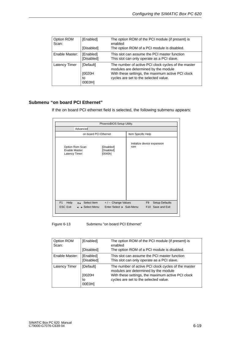
Configuring the SIMATIC Box PC 620
6-19SIMATIC Box PC 620 ManualC79000-G7076-C639-04
Option ROMScan:
[Enabled] The option ROM of the PCI module (if present) isenabled
[Disabled] The option ROM of a PCI module is disabled.
Enable Master: [Enabled] This slot can assume the PCI master function[Disabled] This slot can only operate as a PCI slave.
Latency Timer [Default] The number of active PCI clock cycles of the mastermodules are determined by the module
[0020H With these settings, the maximum active PCI clockto cycles are set to the selected value.00E0H]
Submenu “on board PCI Ethernet”
If the on board PCI ethernet field is selected, the following submenu appears:
PhoenixBIOS Setup Utility.
Item Specific Help
F1
ESC
Help
Exit
Select Item
Select Menu
+ / –
Enter Select
Change Values F9
F10
Setup Defaults
Save and ExitSub-Menu
Advanced
Option Rom Scan [Disabled]Enable Master: [Disabled]
on board PCI Ethernet
Latency Timer: [0040h]
Initialize device expansionrom
Figure 6-13 Submenu ”on board PCI Ethernet”
Option ROMScan:
[Enabled] The option ROM of the PCI module (if present) isenabled
[Disabled] The option ROM of a PCI module is disabled.
Enable Master: [Enabled] This slot can assume the PCI master function[Disabled] This slot can only operate as a PCI slave.
Latency Timer [Default] The number of active PCI clock cycles of the mastermodules are determined by the module
[0020H With these settings, the maximum active PCI clock to cycles are set to the selected value.00E0H]
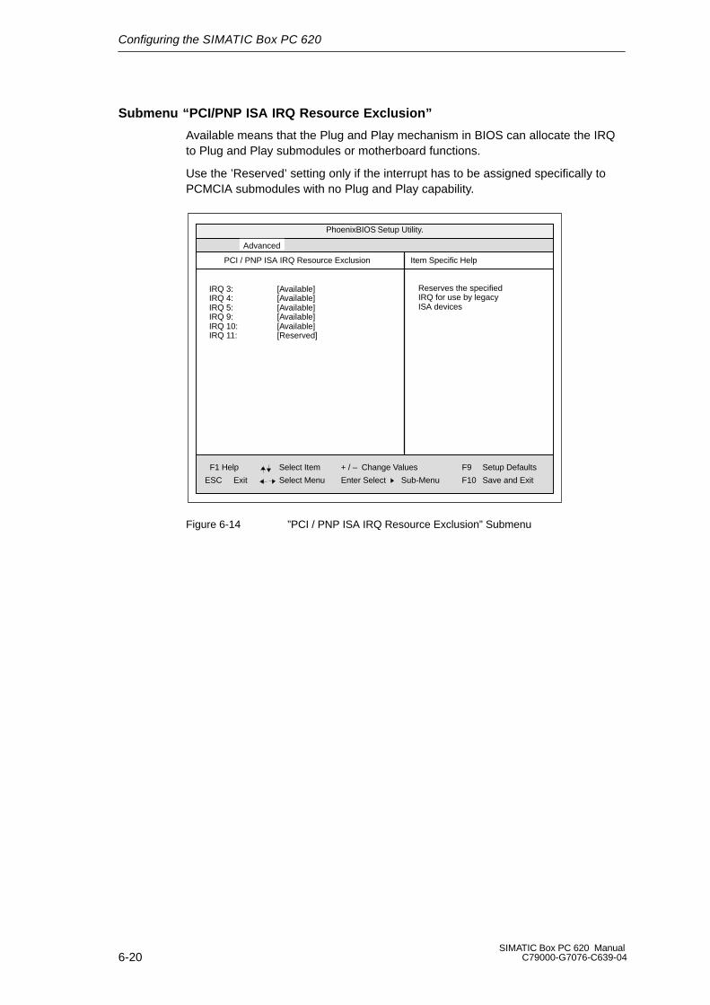
Configuring the SIMATIC Box PC 620
6-20SIMATIC Box PC 620 Manual
C79000-G7076-C639-04
Submenu “PCI/PNP ISA IRQ Resource Exclusion”
Available means that the Plug and Play mechanism in BIOS can allocate the IRQto Plug and Play submodules or motherboard functions.
Use the ’Reserved’ setting only if the interrupt has to be assigned specifically toPCMCIA submodules with no Plug and Play capability.
PhoenixBIOS Setup Utility.
Item Specific Help
ESC Exit
Select Item
Select Menu
+ / –
Enter Select
Change Values F9
F10
Setup Defaults
Save and ExitSub-Menu
IRQ 3:IRQ 4:IRQ 5:IRQ 9:IRQ 10:IRQ 11:
[Available][Available][Available][Available][Available][Reserved]
PCI / PNP ISA IRQ Resource Exclusion
Reserves the specifiedIRQ for use by legacyISA devices
F1 Help
Advanced
Figure 6-14 ”PCI / PNP ISA IRQ Resource Exclusion” Submenu
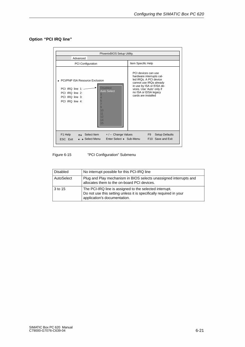
Configuring the SIMATIC Box PC 620
6-21SIMATIC Box PC 620 ManualC79000-G7076-C639-04
Option “PCI IRQ line”
PhoenixBIOS Setup Utility.
Item Specific Help
ESC Exit
Select Item
Select Menu
+ / –
Enter Select
Change Values F9
F10
Setup Defaults
Save and ExitSub-Menu
PCI Configuration
PCI devices can usehardware interrupts cal-led IRQs. A PCI devicecannot use IRQs alreadyin use by ISA or EISA de-vices. Use ’Auto’ only ifno ISA or EISA legacycards are installed
PCI IRQ line 1:PCI IRQ line 2:PCI IRQ line 3:
PCI IRQ line 4:
PCI/PNP ISA Resource Exclusion
DisabledAuto Select345791011121415
F1 Help
Advanced
Figure 6-15 ”PCI Configuration” Submenu
Disabled No interrupt possible for this PCI-IRQ line
AutoSelect Plug and Play mechanism in BIOS selects unassigned interrupts andallocates them to the on-board PCI devices.
3 to 15 The PCI-IRQ line is assigned to the selected interrupt.Do not use this setting unless it is specifically required in yourapplication’s documentation.

Configuring the SIMATIC Box PC 620
6-22SIMATIC Box PC 620 Manual
C79000-G7076-C639-04
6.1.3 The Security Menu
Summary
You can only edit the fields enclosed in square brackets. Two passwords areassigned to protect your PC from unauthorized use. You can use the supervisorpassword to prevent use of diskettes for the normal user and to limit use of thehard disk.
PhoenixBIOS Setup-Utility
Item Specific Help
ESC Exit
Select Item
Select Menu
+ / –
Enter Select
Change Values F9
F10
Setup Defaults
Save and ExitSub-Menu
Supervisor Password is DisabledUser Password is Disabled
Set Supervisor PasswordSet User Password [Enter]
[Enter ]
Password on boot: [Disabled]
Diskette access: [Supervisor]
Fixed disk boot sector: [Normal]
Main Security PowerAdvanced ExitBoot Sequence Version
F1 Help
Supervisor Password controls access to the setup utiliy
Figure 6-16 ”Security” Menu
User Passwordis
Disabled Password is active. BIOS Setup cannot be opened until the password has been entered.
Enabled Certain Setup fields are thus configurable by the user, including the user password.
The field resets automatically from [Disabled] to [Enabled] when thepassword is entered.
Set SupervisorPassword
This field opens the dialog box for entering a password. Once it has beenentered, the supervisor password can be changed or deleted by pressing ”Return” and thus deactivated.
Set UserPassword
This field opens the dialog box for entering a password. Once it has beenentered correctly, the user password can be changed or deleted by pressing ”Return” and thus deactivated.
Password onboot
[Disabled] No password required for system boot.
[Enabled] Supervisor or user password must be entered for system boot.
Fixed disk bootSector
[Normal] All types of hard-disk access are permitted.
[Write protect] No operating system can be installed. This is a way of protecting against boot viruses.
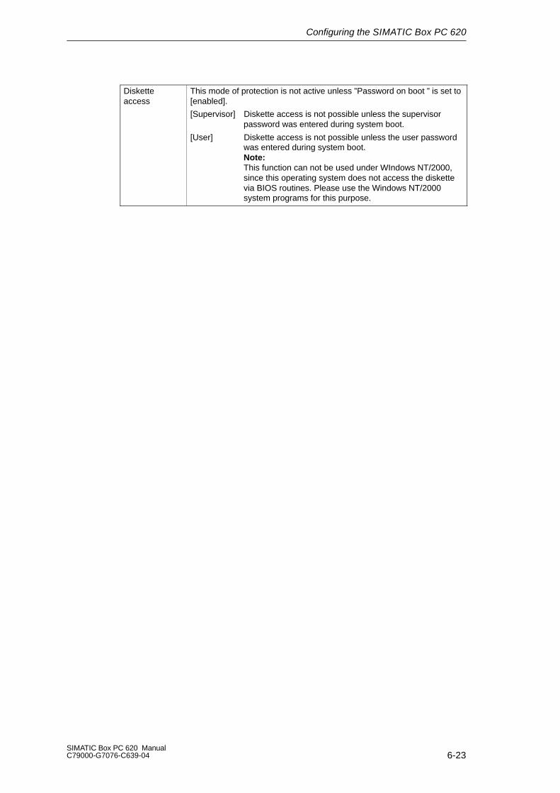
Configuring the SIMATIC Box PC 620
6-23SIMATIC Box PC 620 ManualC79000-G7076-C639-04
Disketteaccess
This mode of protection is not active unless ”Password on boot ” is set to[enabled].
[Supervisor] Diskette access is not possible unless the supervisor password was entered during system boot.
[User] Diskette access is not possible unless the user password was entered during system boot.Note:This function can not be used under WIndows NT/2000,
since this operating system does not access the diskette via BIOS routines. Please use the Windows NT/2000
system programs for this purpose.
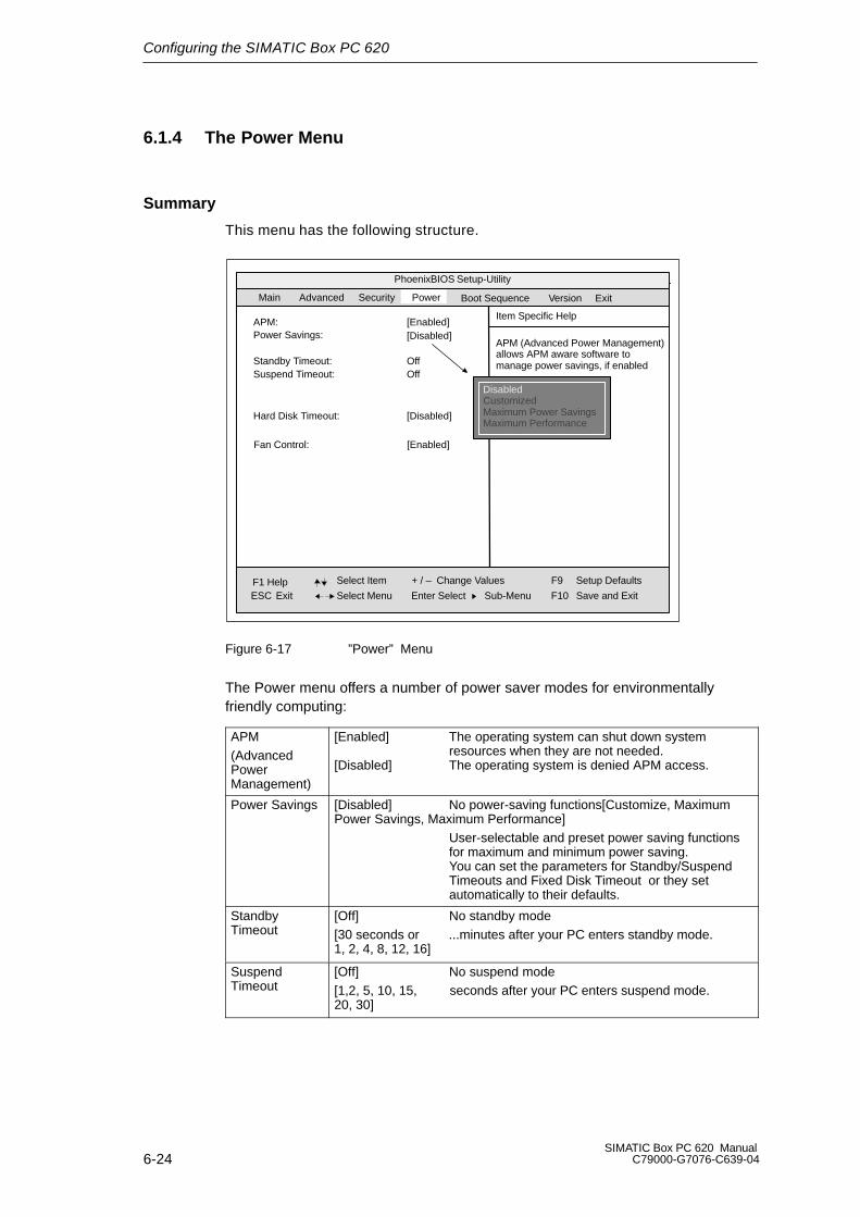
Configuring the SIMATIC Box PC 620
6-24SIMATIC Box PC 620 Manual
C79000-G7076-C639-04
6.1.4 The Power Menu
Summary
This menu has the following structure.
PhoenixBIOS Setup-Utility
Item Specific Help
ESC Exit
Select Item
Select Menu
+ / –
Enter Select
Change Values F9
F10
Setup Defaults
Save and Exit
APM (Advanced Power Management)allows APM aware software tomanage power savings, if enabled
Sub-Menu
Power Savings: [Disabled]
Standby Timeout: OffSuspend Timeout: Off
Hard Disk Timeout: [Disabled]
Main
Security PowerAdvanced
APM: [Enabled]
DisabledCustomizedMaximum Power SavingsMaximum Performance
ExitBoot Sequence Version
F1 Help
Fan Control: [Enabled]
Figure 6-17 ”Power” Menu
The Power menu offers a number of power saver modes for environmentallyfriendly computing:
APM(AdvancedPowerManagement)
[Enabled] The operating system can shut down system resources when they are not needed.
[Disabled] The operating system is denied APM access.
Power Savings [Disabled] No power-saving functions[Customize, MaximumPower Savings, Maximum Performance]
User-selectable and preset power saving functions for maximum and minimum power saving. You can set the parameters for Standby/Suspend Timeouts and Fixed Disk Timeout or they set automatically to their defaults.
Standby Timeout
[Off] No standby mode[30 seconds or ...minutes after your PC enters standby mode.1, 2, 4, 8, 12, 16]
Suspend Timeout
[Off] No suspend mode[1,2, 5, 10, 15, seconds after your PC enters suspend mode.20, 30]

Configuring the SIMATIC Box PC 620
6-25SIMATIC Box PC 620 ManualC79000-G7076-C639-04
Hard Disk Timeout
[Disabled] The hard disk does not shut down.[10, 15, 30, 60] Time since the last hard-disk access, the hard disk
is shut down. The next time it is accessed, the hard disk starts spinning again after a brief delay.
Fan Control [Enabled] Fan always runs at full speed[Enabled] Fan speed depends on temperature.
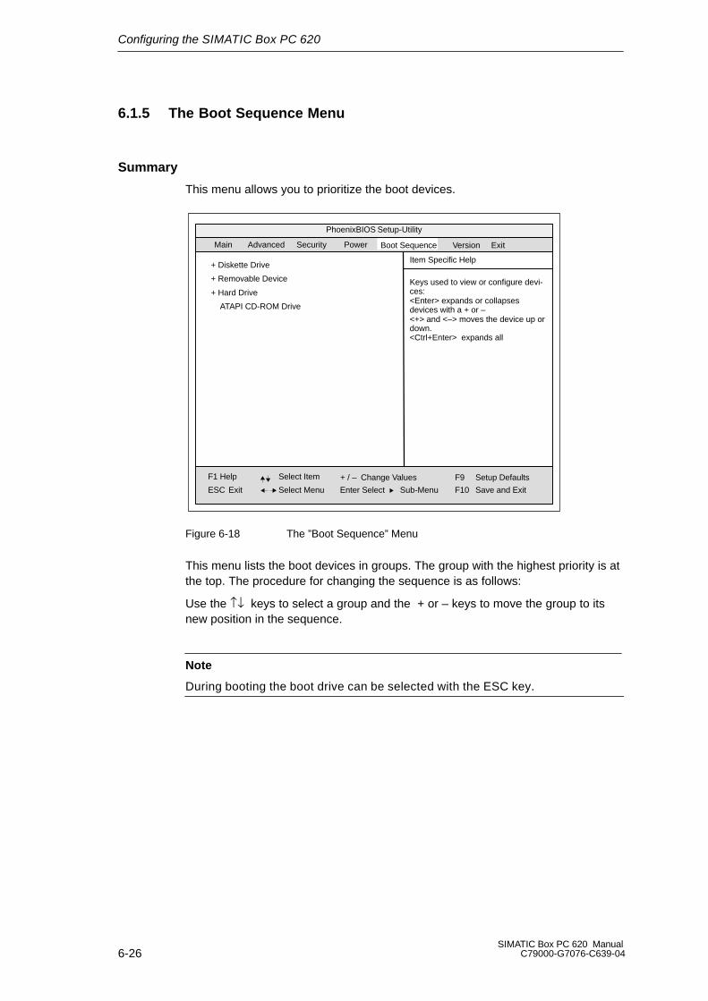
Configuring the SIMATIC Box PC 620
6-26SIMATIC Box PC 620 Manual
C79000-G7076-C639-04
6.1.5 The Boot Sequence Menu
Summary
This menu allows you to prioritize the boot devices.
Boot Sequence
PhoenixBIOS Setup-Utility
Item Specific Help
ESC Exit
Select Item
Select Menu
+ / –
Enter Select
Change Values F9
F10
Setup Defaults
Save and Exit
Keys used to view or configure devi-ces:<Enter> expands or collapses devices with a + or –<+> and <–> moves the device up ordown.<Ctrl+Enter> expands all
Sub-Menu
Main
Security PowerAdvanced
+ Diskette Drive
+ Removable Device
+ Hard Drive
ATAPI CD-ROM Drive
ExitVersion
F1 Help
Figure 6-18 The ”Boot Sequence” Menu
This menu lists the boot devices in groups. The group with the highest priority is atthe top. The procedure for changing the sequence is as follows:
Use the ↑↓ keys to select a group and the + or – keys to move the group to itsnew position in the sequence.
Note
During booting the boot drive can be selected with the ESC key.
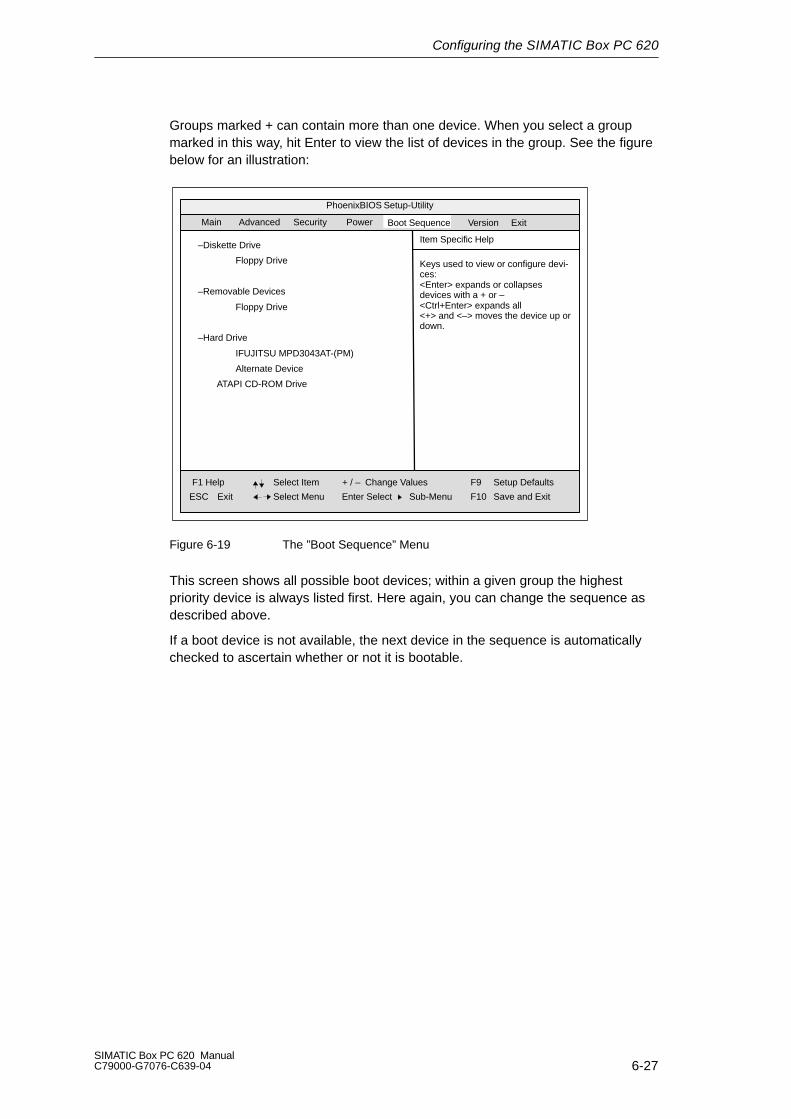
Configuring the SIMATIC Box PC 620
6-27SIMATIC Box PC 620 ManualC79000-G7076-C639-04
Groups marked + can contain more than one device. When you select a groupmarked in this way, hit Enter to view the list of devices in the group. See the figurebelow for an illustration:
Boot Sequence
PhoenixBIOS Setup-Utility
Item Specific Help
ESC Exit
Select Item
Select Menu
+ / –
Enter Select
Change Values F9
F10
Setup Defaults
Save and Exit
Keys used to view or configure devi-ces:<Enter> expands or collapses devices with a + or –<Ctrl+Enter> expands all<+> and <–> moves the device up ordown.
Sub-Menu
Main
Security PowerAdvanced
–Diskette Drive
Floppy Drive
–Removable Devices
Floppy Drive
–Hard Drive
IFUJITSU MPD3043AT-(PM)
Alternate Device
ATAPI CD-ROM Drive
ExitVersion
F1 Help
Figure 6-19 The ”Boot Sequence” Menu
This screen shows all possible boot devices; within a given group the highest priority device is always listed first. Here again, you can change the sequence asdescribed above.
If a boot device is not available, the next device in the sequence is automaticallychecked to ascertain whether or not it is bootable.
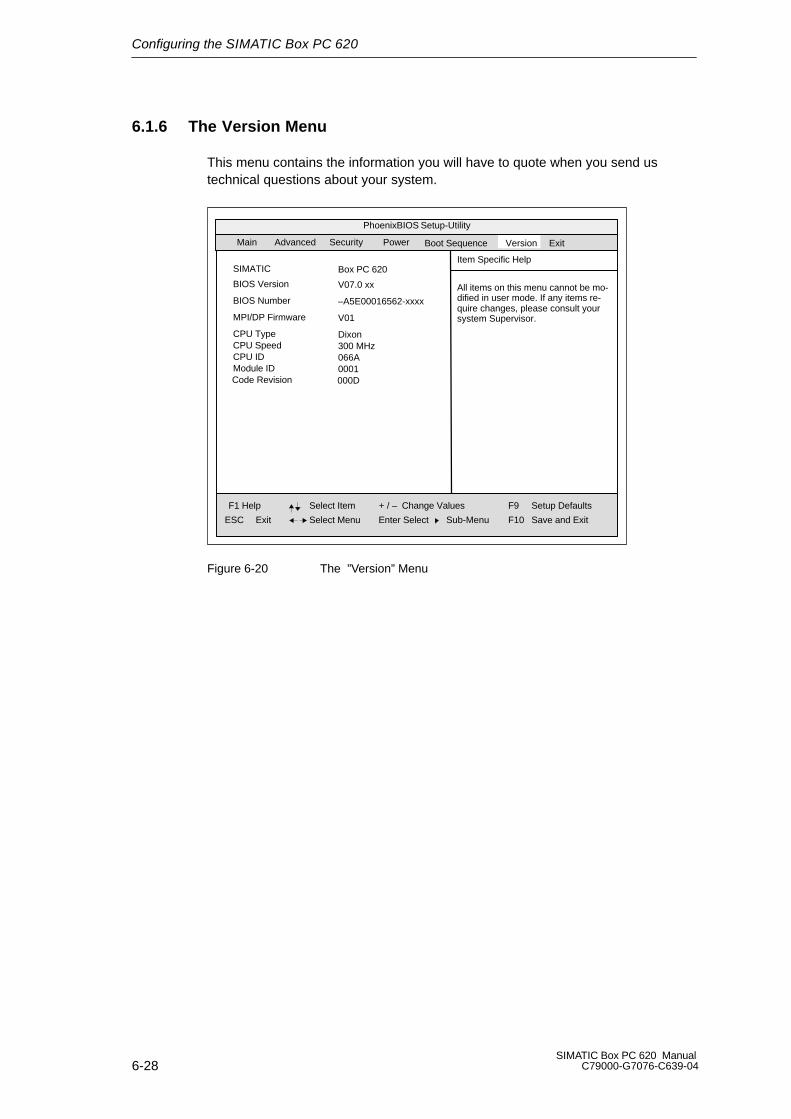
Configuring the SIMATIC Box PC 620
6-28SIMATIC Box PC 620 Manual
C79000-G7076-C639-04
6.1.6 The Version Menu
This menu contains the information you will have to quote when you send us technical questions about your system.
Boot Sequence
PhoenixBIOS Setup-Utility
Item Specific Help
ESC Exit
Select Item
Select Menu
+ / –
Enter Select
Change Values F9
F10
Setup Defaults
Save and Exit
All items on this menu cannot be mo-dified in user mode. If any items re-quire changes, please consult yoursystem Supervisor.
Sub-Menu
Main
Security PowerAdvanced
SIMATIC
ExitVersion
Box PC 620
BIOS Version V07.0 xx
BIOS Number –A5E00016562-xxxx
MPI/DP Firmware V01
CPU Type DixonCPU Speed 300 MHzCPU ID 066AModule ID 0001
F1 Help
Code Revision 000D
Figure 6-20 The ”Version” Menu
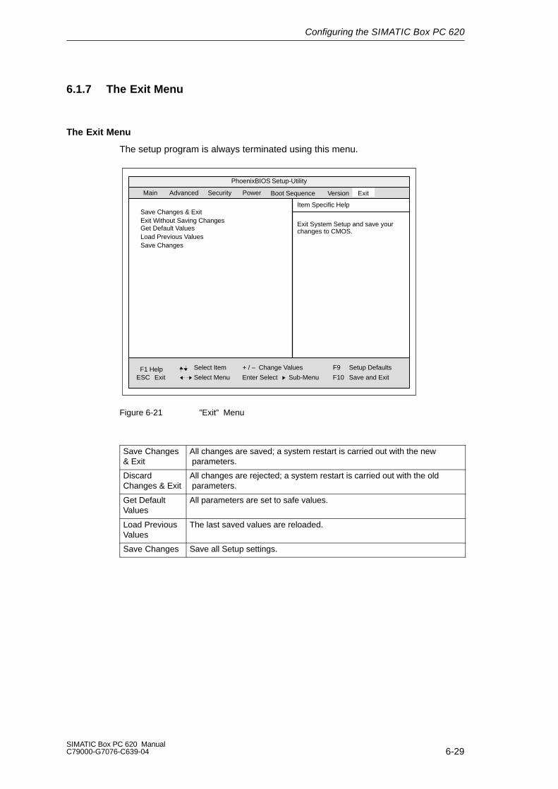
Configuring the SIMATIC Box PC 620
6-29SIMATIC Box PC 620 ManualC79000-G7076-C639-04
6.1.7 The Exit Menu
The Exit Menu
The setup program is always terminated using this menu.
PhoenixBIOS Setup-Utility
Item Specific Help
ESC Exit
Select Item
Select Menu
+ / –
Enter Select
Change Values F9
F10
Setup Defaults
Save and Exit
Exit System Setup and save yourchanges to CMOS.
Sub-Menu
Save Changes & ExitExit Without Saving ChangesGet Default ValuesLoad Previous ValuesSave Changes
Main
Security PowerAdvanced ExitBoot Sequence Version
F1 Help
Figure 6-21 ”Exit” Menu
Save Changes& Exit
All changes are saved; a system restart is carried out with the new parameters.
DiscardChanges & Exit
All changes are rejected; a system restart is carried out with the old parameters.
Get DefaultValues
All parameters are set to safe values.
Load PreviousValues
The last saved values are reloaded.
Save Changes Save all Setup settings.

Configuring the SIMATIC Box PC 620
6-30SIMATIC Box PC 620 Manual
C79000-G7076-C639-04
6.1.8 Default Setup Settings
Documenting Your Device Configuration
If you have made any modifications to the default Setup settings, you can enterthem in the following table. You can then refer to these entries if you need to makeany hardware modifications later.
Note
Print the following table out and keep the pages in a safe place once you havefilled in your entries.
Systemparameter Default Settings YourEntriesMainSystem Time hh:mm:ssSystem Date MM/TT/JJJJDiskette A 1,44 MB, 3 1/2” / bei LS 120:
DisabledPrimary Master C: 4326 MBPrimary Slave NoneSecondary Master noneSecondary Slave None
Memory Cache Write back
Boot OptionsQuick Boot Mode EnabledSETUP prompt EnabledPOST Errors EnabledFloppy check DisabledSummary screen Enabled
Keyboard FeaturesNum Lock OnKey Click DisabledKeyboard auto-repeat rate: 30/sKeyboard auto-repeat delay 1/2s
Hardware OptionsPCI-MPI/DP: EnabledOn Board Ethernet EnabledEthernet Adress 08000624xxxxCardbus/PCMCIA Slot EnabledSafeCard Functions EnabledLegacy USB Suport DisabledCRT/LCD selection SIMULTAN
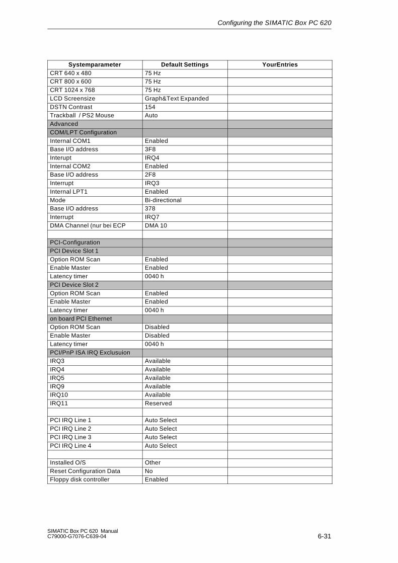
Configuring the SIMATIC Box PC 620
6-31SIMATIC Box PC 620 ManualC79000-G7076-C639-04
Systemparameter YourEntriesDefault SettingsCRT 640 x 480 75 HzCRT 800 x 600 75 HzCRT 1024 x 768 75 HzLCD Screensize Graph&Text ExpandedDSTN Contrast 154Trackball / PS2 Mouse AutoAdvancedCOM/LPT ConfigurationInternal COM1 EnabledBase I/O address 3F8Interupt IRQ4Internal COM2 EnabledBase I/O address 2F8Interrupt IRQ3Internal LPT1 EnabledMode Bi-directionalBase I/O address 378Interrupt IRQ7DMA Channel (nur bei ECP DMA 10
PCI-ConfigurationPCI Device Slot 1Option ROM Scan EnabledEnable Master EnabledLatency timer 0040 hPCI Device Slot 2Option ROM Scan EnabledEnable Master EnabledLatency timer 0040 hon board PCI EthernetOption ROM Scan DisabledEnable Master DisabledLatency timer 0040 hPCI/PnP ISA IRQ ExclusuionIRQ3 AvailableIRQ4 AvailableIRQ5 AvailableIRQ9 AvailableIRQ10 AvailableIRQ11 Reserved
PCI IRQ Line 1 Auto SelectPCI IRQ Line 2 Auto SelectPCI IRQ Line 3 Auto SelectPCI IRQ Line 4 Auto Select
Installed O/S OtherReset Configuration Data NoFloppy disk controller Enabled

Configuring the SIMATIC Box PC 620
6-32SIMATIC Box PC 620 Manual
C79000-G7076-C639-04
Systemparameter YourEntriesDefault SettingsLocal Bus IDE adapter Primary & SecondaryLarge Disk Access Mode DOSHard Disk Pre-Delay DisabledMemory Gap at 15 Mbyte Disabled
SecuritySupervisor Password Is DisabledUser Password Is DisabledSet Supervisor Password EnterSet User Password EnterPassword on boot DisabledFixed disk boot sector NormalDiskette Access Supervisor
PowerAPM EnabledPower Savings DisabledStandby Timeout offSuspend Timeout offHard Disk Timeout DisabledFan Control Enabled
Boot SequenceDiskette DriveRemovable DevicesHard DriveATAPI CD-ROM Drive
VersionSIMATIC Box PC 620BIOS Version V7.xxBIOS Number A5E16562-ESxxMPI/DP Firmware V01CPU Type CeleronCPU Speed 300 MHzCPU IDCode Revision 0015
Configuring the SIMATIC Box PC 620
6-33SIMATIC Box PC 620 ManualC79000-G7076-C639-04
6.2 Configuring the PC Card
You can obtain the software you require for using PC cards under MS DOS, suchas
Socket Services
Card Services
Client Drivers
Flash File System
from the nearest Siemens sales office or representative.
Your PC comes supplied with Windows 98 / NT4 / 2000 already installed; this sup-ports the PC Card interface.
After configuration, the computer must be rebooted.

Configuring the SIMATIC Box PC 620
6-34SIMATIC Box PC 620 Manual
C79000-G7076-C639-04
7-1SIMATIC Box PC 620 ManualC79000-G7076-C639-04
Error Diagnosis
Overview of Chapter
In chapter you will find on page
7.1 Diagnosing errors 7-2
7.2 Self-test of the SIMATIC Box PC 620 before booting 7-3
7

Error Diagnosis
7-2SIMATIC Box PC 620 Manual
C79000-G7076-C639-04
7.1 Diagnosing Errors
Error Cause Remedy
Power–ON LED is not lit Connection to power supplyis faulty
Check the connection to thepower supply, mains cable,mains plug
The message:”Invalid configuration information... Press the F1 keyto continue, F2 to run Setuputility”appears on the display/monitor
Incorrect configuration data Back-up battery defective or
dead
Press the ”F2” key, check theconfiguration data in the Setup program, enter defaultvalues if necessary, checkerror messages in the firstSetup mask
The message: ”No boot deviceavailable”appears on the display/monitor
No bootable disk in the drive Wrong hard disk type entered
in Setup
Use the ”Fixed Disk Function”in the Setup program
Message: ”Keyboard stuck keyfailure”
A blocked key was found during the system self-test ofthe keyboard
Check keyboard Restart system
The power–up of the PC isterminated after several beeps
An error occurred during thesystem self-test
Check hardware (see also Section 2.1).
Every time a key is pressed, abeep sounds withoutcharacters being displayed
Keyboard buffer overflow <CTRL> <PAUSE>
Not ready error whenattempting to read from floppydisk
No floppy disk inserted Floppy disk is not formatted
Insert floppy disk Format floppy disk
Write protection error occurswhen attempting to write tofloppy disk
Floppy disk is write protected The gate is open with 3.5’’
format
Remove write protection
No response from portsCOM1,COM2, LPT1 or MPI/DP
Ports are set to ”Disabled”inthe Setup program.
Set the ports COM1,COM2,LPT1 or MPI/DP to ”Enabled”in the submenu ”HardwareOptions” in the Setup pro-gram.
<\> key is not displayed Incorrect keyboard driverbeing used
Load correct keyboard driver <ALT> <9> <2>
Mouse does not function Mouse ball is not rotating No/wrong mouse driver
Clean mouse ball andhousing
Load correct mouse driver
Mouse cursor cannot be moved
The PS/2 port is set to”disabled” in setup
Check setup entry
Mouse cursor moves jerkily Mouse ball is dirty Clean mouse ball andhousing
Drive cover cannot be opened Filter cover is not locatedcorrectly
Press filter cover on firmly

Error Diagnosis
7-3SIMATIC Box PC 620 ManualC79000-G7076-C639-04
7.2 Self-Test of the SIMATIC Box PC 620 before Booting
When the PC is powered up, it runs a self-test (POST = Power On Self Test). If thePOST detects a fault, it outputs the sequence of beeps (beep code) assigned forthe fault. Each beep code consists of 2 x 2 sequences.
Conversion table for the beep codes to hexadecimal representation:
Beeps Hex-Code
B B 0
B BB 1
B BBB 2
B BBBB 3
BB B 4
BB BB 5
BB BBB 6
BB BBBB 7
BBB B 8
BBB BB 9
BBB BBB A
BBB BBBB B
BBBB B C
BBBB BB D
BBBB BBB E
BBBB BBBB F
Example:
B BBBB BBB BBB Beeps
3 6 Hex-Code
Check shutdown code Meaning
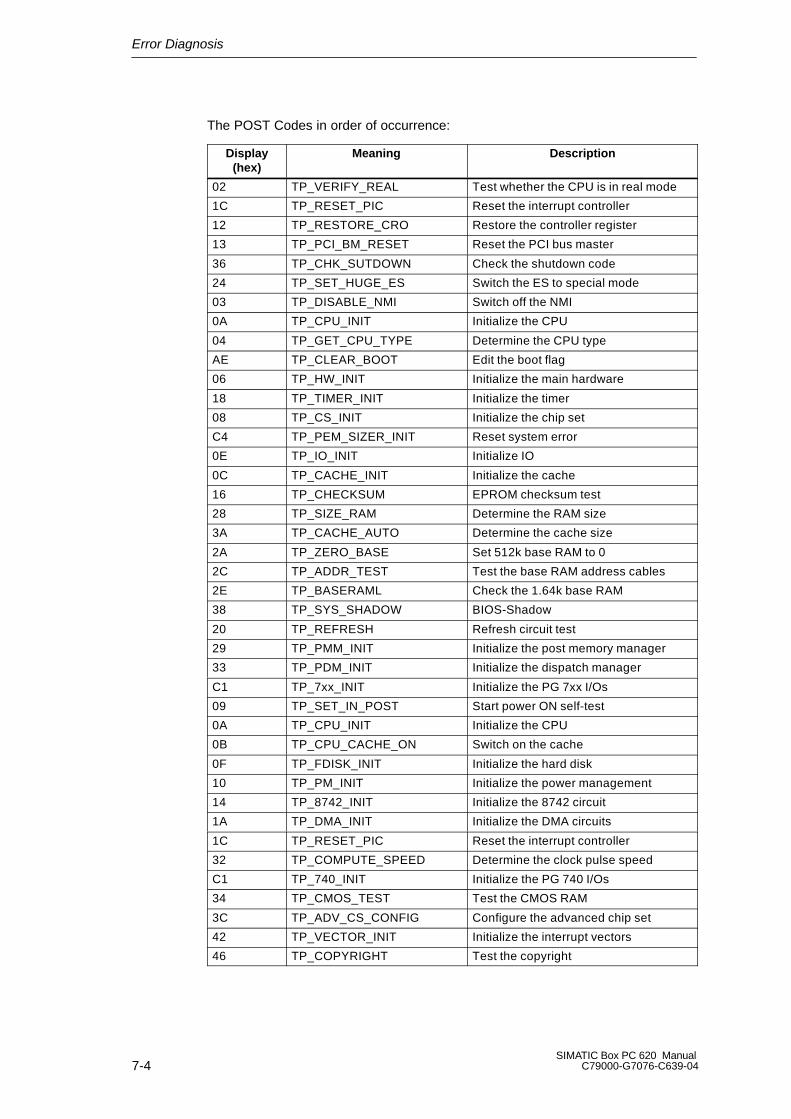
Error Diagnosis
7-4SIMATIC Box PC 620 Manual
C79000-G7076-C639-04
The POST Codes in order of occurrence:
Display(hex)
Meaning Description
02 TP_VERIFY_REAL Test whether the CPU is in real mode
1C TP_RESET_PIC Reset the interrupt controller
12 TP_RESTORE_CRO Restore the controller register
13 TP_PCI_BM_RESET Reset the PCI bus master
36 TP_CHK_SUTDOWN Check the shutdown code
24 TP_SET_HUGE_ES Switch the ES to special mode
03 TP_DISABLE_NMI Switch off the NMI
0A TP_CPU_INIT Initialize the CPU
04 TP_GET_CPU_TYPE Determine the CPU type
AE TP_CLEAR_BOOT Edit the boot flag
06 TP_HW_INIT Initialize the main hardware
18 TP_TIMER_INIT Initialize the timer
08 TP_CS_INIT Initialize the chip set
C4 TP_PEM_SIZER_INIT Reset system error
0E TP_IO_INIT Initialize IO
0C TP_CACHE_INIT Initialize the cache
16 TP_CHECKSUM EPROM checksum test
28 TP_SIZE_RAM Determine the RAM size
3A TP_CACHE_AUTO Determine the cache size
2A TP_ZERO_BASE Set 512k base RAM to 0
2C TP_ADDR_TEST Test the base RAM address cables
2E TP_BASERAML Check the 1.64k base RAM
38 TP_SYS_SHADOW BIOS-Shadow
20 TP_REFRESH Refresh circuit test
29 TP_PMM_INIT Initialize the post memory manager
33 TP_PDM_INIT Initialize the dispatch manager
C1 TP_7xx_INIT Initialize the PG 7xx I/Os
09 TP_SET_IN_POST Start power ON self-test
0A TP_CPU_INIT Initialize the CPU
0B TP_CPU_CACHE_ON Switch on the cache
0F TP_FDISK_INIT Initialize the hard disk
10 TP_PM_INIT Initialize the power management
14 TP_8742_INIT Initialize the 8742 circuit
1A TP_DMA_INIT Initialize the DMA circuits
1C TP_RESET_PIC Reset the interrupt controller
32 TP_COMPUTE_SPEED Determine the clock pulse speed
C1 TP_740_INIT Initialize the PG 740 I/Os
34 TP_CMOS_TEST Test the CMOS RAM
3C TP_ADV_CS_CONFIG Configure the advanced chip set
42 TP_VECTOR_INIT Initialize the interrupt vectors
46 TP_COPYRIGHT Test the copyright

Error Diagnosis
7-5SIMATIC Box PC 620 ManualC79000-G7076-C639-04
Display(hex)
DescriptionMeaning
49 TP_PCI_INIT Initialize the PCI interface
48 TP_CONFIG Check the configuration
4A TP_VIDEO Initialize the video interface
4C TP_VID_SHADOW Copy the video BIOS to RAM
24 TP_SET_HUGE_ES Switch the ES to special mode
22 TP_8742_TEST Test circuit 8742
52 TP_KB_TEST Keyboard available?
54 TP_KEY_CLICK Switch the keyboard click on/off
76 TP_KEYBOARD Check the keyboard
58 TP_HOT_INT Test for unexpected interrupts
4B TP_QUIETBOOT_START Switch off any boot messages
4E TP_CR_DISPLAY Display the copyright notice
50 TP_CPU_DISPLAY Display the CPU type
5A TP_DISPLAY_F2 Display the F2 message for “SETUP”
5B TP_CPU_CACHE_OFF Switch off the cache if applicable(SETUP setting)
5C TP_MEMORY_TEST Test the system memory
60 TP_EXT_MEMORY Test the extended memory
62 TP_EXT_ADDR Test the A20 address line
64 TP_USERPATCH1 Area for own initializations
66 TP_CACHE_ADVNCD Determine and enable the cache size
68 TP_CACHE_CONFIG Configure and test the cache
6A TP_DISP_CACHE Display the cache configuration
6C TP_DISP_SHADOWS Configuration and size of the shadowDisplay RAM
6E TP_DISP_NONDISP Display nondisposable segment
70 TP_ERROR_MSGS Display post error
72 TP_TEST_CONFIG Check SETUP irregularities
7C TP_HW_INTS Set the IRQ vectors
7E TP_COPROC Check whether the CO processor ispresent
96 TP_CLEAR_HUGE_ES Switch the ES back
80 TP_IO_BEFORE Disable IO circuits
88 TP_BIOS_INIT Initialize the BIOS data area
8A TP_INIT_EXT_BDA Initialize the external BIOS data area
85 TP_PCI_PCC Determine the PCI circuits
82 TP_RS232 Determine the serial interfaces
84 TP_LPT Determine the parallel interface
86 TP_IO_AFTER Reenable the IO circuits
83 TP_FDISK_CFG_IDE_CTRLR Configure the IDE controller
89 TP_ENABLE_NMI Enable the NMI
8C TP_FLOPPY Initialize the floppy controller
90 TP_FDISK Initialize the hard disk controller
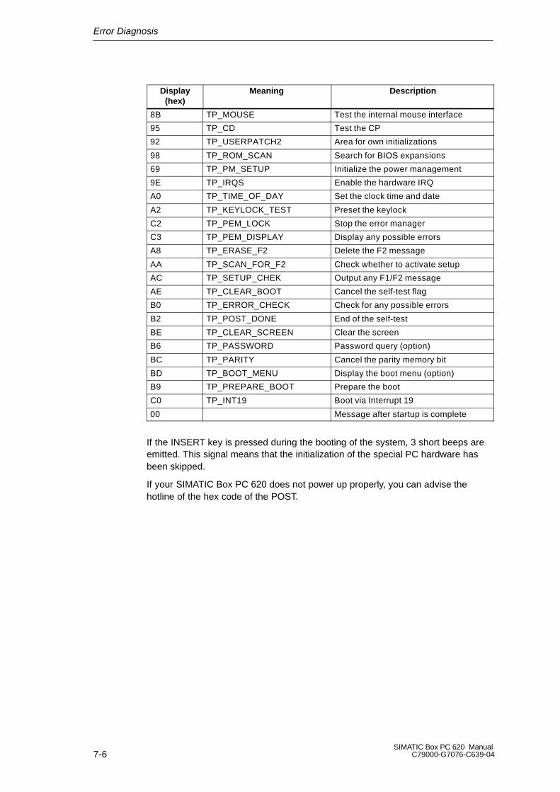
Error Diagnosis
7-6SIMATIC Box PC 620 Manual
C79000-G7076-C639-04
Display(hex)
DescriptionMeaning
8B TP_MOUSE Test the internal mouse interface
95 TP_CD Test the CP
92 TP_USERPATCH2 Area for own initializations
98 TP_ROM_SCAN Search for BIOS expansions
69 TP_PM_SETUP Initialize the power management
9E TP_IRQS Enable the hardware IRQ
A0 TP_TIME_OF_DAY Set the clock time and date
A2 TP_KEYLOCK_TEST Preset the keylock
C2 TP_PEM_LOCK Stop the error manager
C3 TP_PEM_DISPLAY Display any possible errors
A8 TP_ERASE_F2 Delete the F2 message
AA TP_SCAN_FOR_F2 Check whether to activate setup
AC TP_SETUP_CHEK Output any F1/F2 message
AE TP_CLEAR_BOOT Cancel the self-test flag
B0 TP_ERROR_CHECK Check for any possible errors
B2 TP_POST_DONE End of the self-test
BE TP_CLEAR_SCREEN Clear the screen
B6 TP_PASSWORD Password query (option)
BC TP_PARITY Cancel the parity memory bit
BD TP_BOOT_MENU Display the boot menu (option)
B9 TP_PREPARE_BOOT Prepare the boot
C0 TP_INT19 Boot via Interrupt 19
00 Message after startup is complete
If the INSERT key is pressed during the booting of the system, 3 short beeps areemitted. This signal means that the initialization of the special PC hardware hasbeen skipped.
If your SIMATIC Box PC 620 does not power up properly, you can advise thehotline of the hex code of the POST.
8-1SIMATIC Box PC 620 ManualC79000-G7076-C639-04
Hardware Information
Overview of Chapter
In chapter you will find on page
8.1 Current Requirement of the Components (Maximum Values) 8-2
8.2 Overview of the Components and Ports 8-3
8.3 Hardware Address Table 8-4
8.4 Interrupt Assignment 8-8
8.5 Video Modes of the SIMATIC Box PC 620 8-10
8.6 Monitoring Functions 8-11
8.7 Ports 8-14
8.8 Bus Unit 8-38
8.9 CD-ROM Drive 8-44
8.10 Power Supply Unit (AC) 8-46
8.11 Power Supply Unit (DC) 8-47
8.12 Connecting Cables 8-48
8

Hardware Information
8-2SIMATIC Box PC 620 Manual
C79000-G7076-C639-04
8.1 Current Requirement of the Components (Maximum Values)
Basic System
Component Voltage
+5V +3.3V +12V +18V –5V –12V
Pentium II Motherboard 0.5 A 1.9 A 0.1 A 0.08 A 0.02 A
Processor Pentium II 333 1.8 A
Floppy disk drive / LS 120 0.56 A
Hard disk 0.56 A 0.4 A
CD ROM drive 0.7 A
Fan 0.2 A
Sum (basic configuration) 4.12 A 1.9 A 0.7 A 0.08 A 0 A 0.02 A
ISA/PCI slots (Sum) 3 A 0.6 A 0.1 A 0.1 A
PC-Card slot 0.5 1 0.6 A 1 0.12 A
Sum (max. for maximumconfiguration)
10 A 2 4.2 A 1.7 A 3 0.080 A 0.1 A 0.2 A
Total power consumption 84W
1 Alternative 5V or 3.3V2 11A, if the total power consumption is not exceeded3 3A, if the total power consumption is not exceeded
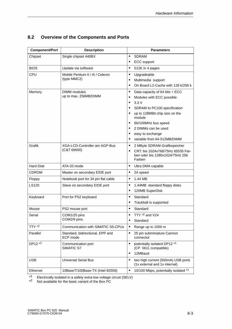
Hardware Information
8-3SIMATIC Box PC 620 ManualC79000-G7076-C639-04
8.2 Overview of the Components and Ports
Component/Port Description Parameters
Chipset Single chipset 440BX SDRAM
ECC support
BIOS Update via software 512K in 4 pages
CPU Mobile Pentium II / III / Celeron(type MMC2)
Upgradeable
Multimedia support
On Board L2-Cache with 128 k/256 k
Memory DIMM modulesup to max. 256MB/DIMM
Data capacity of 64 bits + ECC
Modules with ECC possible
3.3 V
SDRAM to PC100 specification
up to 128MBit chip size on the module
66/100MHz bus speed
2 DIMMs can be used
easy to exchange
variable from 64-512MB/DIMM
Grafik XGA-LCD-Controller am AGP-Bus(C&T 69000)
2 MByte SDRAM-Grafikspeicher
CRT: bis 1024x768/75Hz 65535 Far-ben oder bis 1280x1024/75Hz 256Farben
Hard Disk ATA-33 mode Ultra DMA capable
CDROM Master on secondary EIDE port 24 speed
Floppy Notebook port for 34 pin flat cable 1.44 MB
LS120 Slave on secondary EIDE port 1.44MB standard floppy disks
120MB SuperDisk
Keyboard Port for PS2 keyboard Standard
Trackball is supported
Mouse PS2 mouse port Standard
Serial COM1/25 pinsCOM2/9 pins.
TTY *2 and V24
Standard
TTY *2 Communication with SIMATIC S5-CPUs Range up to 1000 m
Parallel Standard, bidirectional, EPP andECP mode
25 pin subminiature Cannon connector
DP12 *2 Communication port SIMATIC S7
potentially isolated DP12 *1
(CP 5611 compatible)
12MBaud
USB Universal Serial Bus two high current (500mA) USB ports(1x external and 1x internal)
Ethernet 10BaseT/100Base-TX (Intel 82559) 10/100 Mbps, potentially isolated *1
*1 Electrically isolated in a safety extra-low voltage circuit (SELV)*2 Not available for the basic variant of the Box PC
Hardware Information
8-4SIMATIC Box PC 620 Manual
C79000-G7076-C639-04
8.3 Hardware Address Table
In the distribution of the address areas a distinction is made between
Memory address area and
I/O address area.
Different read/write signals (I/O WR, I/O RD, MEMR, MEMR) are used toreference these areas. The following tables will give you an overview of theaddress areas used. Please refer to the descriptions of the individual functionalgroups for more details.
Functional Principle of the Memory Decoding
The Pentium II CPU has a memory address area of 64 Gbytes, of which 4GBytescan be used. The CPU has 64 data lines, 33 address lines and 8 byte lines (BE0 ... BE7), which encode the unavailable address lines A0, A1 and A2.
The CPU address bus is mapped via the PAC (System Controller) on the PCI address bus. The memory addresses of addresses 0000 0000h to 0009 FFFFh(640kByte) and addresses 0010 0000h to 2FFF FFFFh (768MByte) are excludedhere.
The ISA bridge PIIX (PCI ISA IDE Xcellerator) precisely maps the ISA address busonce on the PCI address bus. The ISA address bus for 8 bit modules includes theaddress area from A0 to A19, which corresponds to the CPU addresses0000 0000h to 000F FFFFh (1MByte).
For 16Bit ISA modules, the address bus is expanded by the address linesA20...A23, and therefore addresses 0000 0000h to 00FF FFFFh (16MByte). Thedistinction between the 1MByte and the 16MByte ISA address area is made byspecial Memory–Read/Write signals, which are only activated if the address linesA20, A21, A22 and A23 have a logical zero level.
If address ranges which are occupied by the main memory or PCI bus are addressed by the CPU, no ISA bus control signals are generated, i.e. an ISA busunit is not addressed in these memory areas. Conversely, an ISA busmaster cannot reach addresses above 16MByte. In order to obtain a larger address areafor dual-port RAM expansions than the memory address area between 640kByteand 1MByte, various decoding holes are provided in the Pentium PU basic board:
The CPU address area FFF0 0000h to FFFD FFFFh (1024k–128 k BIOS =896 kByte) is mapped in the ISA address area 00F0 0000h to 00FD FFFFh andis always addressed in the CPU address area. The decoding of the addresslines A24 to A31 missing on the ISA bus is effected by special hardware on thebasic board.
The CPU address area 00F0 0000 to 00FF FFFF is mapped in theISA address area 00F0 0000 to 00FF FFFF (16 MByte memory window).This setting can be toggled on or off in setup.
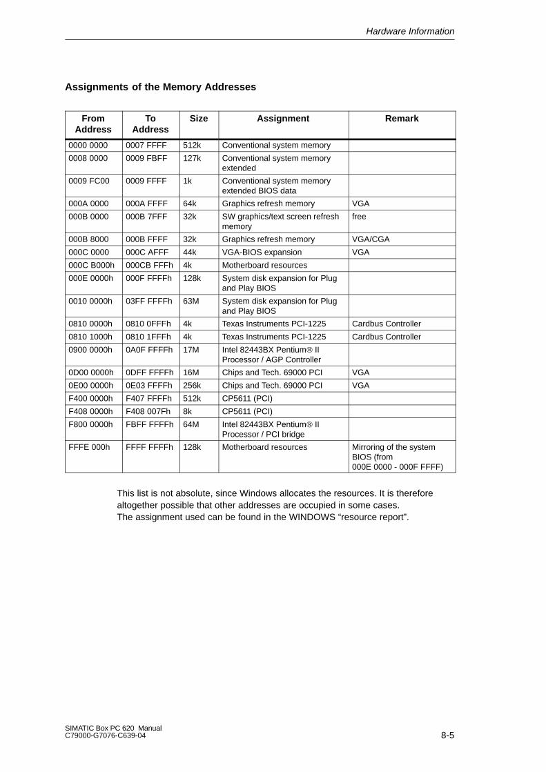
Hardware Information
8-5SIMATIC Box PC 620 ManualC79000-G7076-C639-04
Assignments of the Memory Addresses
FromAddress
ToAddress
Size Assignment Remark
0000 0000 0007 FFFF 512k Conventional system memory
0008 0000 0009 FBFF 127k Conventional system memoryextended
0009 FC00 0009 FFFF 1k Conventional system memoryextended BIOS data
000A 0000 000A FFFF 64k Graphics refresh memory VGA
000B 0000 000B 7FFF 32k SW graphics/text screen refreshmemory
free
000B 8000 000B FFFF 32k Graphics refresh memory VGA/CGA
000C 0000 000C AFFF 44k VGA-BIOS expansion VGA
000C B000h 000CB FFFh 4k Motherboard resources
000E 0000h 000F FFFFh 128k System disk expansion for Plugand Play BIOS
0010 0000h 03FF FFFFh 63M System disk expansion for Plugand Play BIOS
0810 0000h 0810 0FFFh 4k Texas Instruments PCI-1225 Cardbus Controller
0810 1000h 0810 1FFFh 4k Texas Instruments PCI-1225 Cardbus Controller
0900 0000h 0A0F FFFFh 17M Intel 82443BX Pentium IIProcessor / AGP Controller
0D00 0000h 0DFF FFFFh 16M Chips and Tech. 69000 PCI VGA
0E00 0000h 0E03 FFFFh 256k Chips and Tech. 69000 PCI VGA
F400 0000h F407 FFFFh 512k CP5611 (PCI)
F408 0000h F408 007Fh 8k CP5611 (PCI)
F800 0000h FBFF FFFFh 64M Intel 82443BX Pentium II Processor / PCI bridge
FFFE 000h FFFF FFFFh 128k Motherboard resources Mirroring of the systemBIOS (from 000E 0000 - 000F FFFF)
This list is not absolute, since Windows allocates the resources. It is thereforealtogether possible that other addresses are occupied in some cases. The assignment used can be found in the WINDOWS “resource report”.
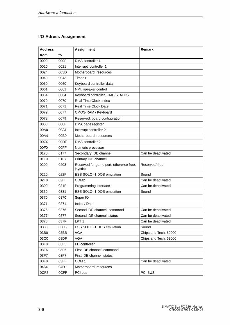
Hardware Information
8-6SIMATIC Box PC 620 Manual
C79000-G7076-C639-04
I/O Adress Assignment
Address Assignment Remark
from to
0000 000F DMA controller 1
0020 0021 Interrupt controller 1
0024 003D Motherboard resources
0040 0043 Timer 1
0060 0060 Keyboard controller data
0061 0061 NMI, speaker control
0064 0064 Keyboard controller, CMD/STATUS
0070 0070 Real Time Clock-Index
0071 0071 Real Time Clock Date
0072 0077 CMOS-RAM / Keyboard
0078 0079 Reserved, board configuration
0080 008F DMA page register
00A0 00A1 Interrupt controller 2
00A4 00B9 Motherboard resources
00C0 00DF DMA controller 2
00F0 00FF Numeric processor
0170 0177 Secondary IDE channel Can be deactivated
01F0 01F7 Primary IDE channel
0200 0203 Reserved for game port, otherwise free,joystick
Reserved/ free
0220 022F ESS SOLO -1 DOS emulation Sound
02F8 02FF COM2 Can be deactivated
0300 031F Programming interface Can be deactivated
0330 0331 ESS SOLO -1 DOS emulation Sound
0370 0370 Super IO
0371 0371 Index / Data
0376 0376 Second IDE channel, command Can be deactivated
0377 0377 Second IDE channel, status Can be deactivated
0378 037F LPT 1 Can be deactivated
0388 038B ESS SOLO -1 DOS emulation Sound
03B0 03BB VGA Chips and Tech. 69000
03C0 03DF VGA Chips and Tech. 69000
03F0 03F5 FD controller
03F6 03F6 First IDE channel, command
03F7 03F7 First IDE channel, status
03F8 03FF COM 1 Can be deactivated
04D0 04D1 Motherboard resources
0CF8 0CFF PCI bus PCI BUS
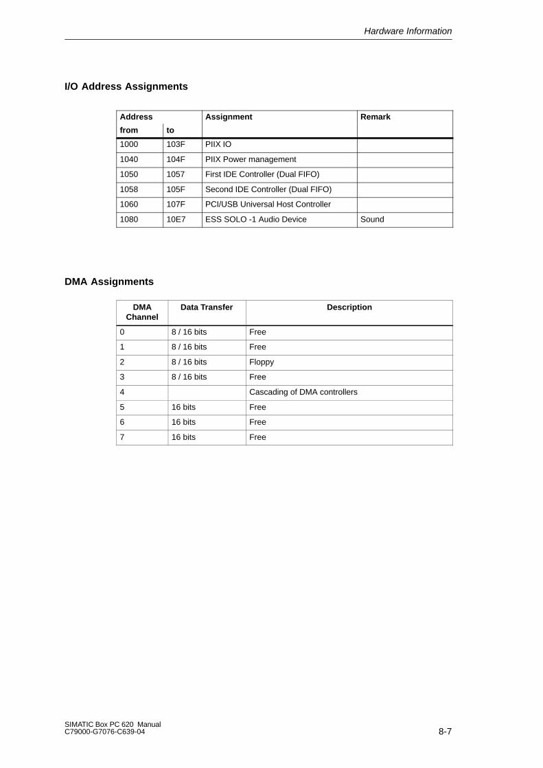
Hardware Information
8-7SIMATIC Box PC 620 ManualC79000-G7076-C639-04
I/O Address Assignments
Address Assignment Remark
from to
1000 103F PIIX IO
1040 104F PIIX Power management
1050 1057 First IDE Controller (Dual FIFO)
1058 105F Second IDE Controller (Dual FIFO)
1060 107F PCI/USB Universal Host Controller
1080 10E7 ESS SOLO -1 Audio Device Sound
DMA Assignments
DMAChannel
Data Transfer Description
0 8 / 16 bits Free
1 8 / 16 bits Free
2 8 / 16 bits Floppy
3 8 / 16 bits Free
4 Cascading of DMA controllers
5 16 bits Free
6 16 bits Free
7 16 bits Free
Hardware Information
8-8SIMATIC Box PC 620 Manual
C79000-G7076-C639-04
8.4 Interrupt Assignments
Interrupt Assignment
In the SIMATIC Box PC 620, the 16 hardware interrupts (IRQ 0 to IRQ 15) are processed by two integrated interrupt controllers of the type 82C59.
The INT output of the slave controller is connected to the IRQ 2 input of the mastercontroller. Interrupt 9 (IRQ 9) can be used on the bus for the assigned interrupt 2(IRQ 2). In the initialization phase, IRQ is programmed for the software interruptvector 0A H (IRQ 2) by the ROM-BIOS.
Priority
The interrupts are priority-scheduled in the reverse order of their numbering.Interrupt IRQ 0 has the highest priority and interrupt IRQ 7 the lowest. Fortriggering IRQ 2, interrupt IRQ 8 has the highest priority and interrupt IRQ15 thelowest. Interrupts IRQ 8 to IRQ 15 therefore have priority over interrupts IRQ 3 toIRQ 7. The interrupt vectors are initialized and masked when theSIMATIC Box PC 620 is powered up.

Hardware Information
8-9SIMATIC Box PC 620 ManualC79000-G7076-C639-04
I/O Adresses of the Interrupt Controllers
Interrupt Assignment Parameterizedinterrupt vector,
memoryaddress
SMI System management interrupt, cannot be masked -
NMI Expansion slots Signal IO Channel Check2 INT 2 H
IRQ 0 Interner Timer (system clock) INT 8 H
IRQ 1 Keyboard INT 9 H
IRQ 2 Cascaded (slave interrupt controller) INT A H
IRQ 3 *) Serial port 2 ( COM2/ IRDA ) [can be cleared in setup] INT B H
IRQ 4 *) Serial por 1 (COM1/TTY) [can be cleared in setup] INT C H
IRQ 5 **) Cardbus Controller INT D H
IRQ 6 *) Floppy Controller INT E H
IRQ 7 *) Parallel Port 1 (parallel printer port LPT1/EPP/ECP) [can becleared in setup]
INT F H
IRQ 8 Battery-backed real-time clock (RTC) INT 70 H
IRQ 9 VGA controller [generally not used] INT 71 H
IRQ 10 Cardbus controller INT 72 H
IRQ 11 *) Safecard On Motherboard INT 73 H
IRQ 12 *) PS/2 mouse or trackball in keyboard. Can be cleared in setup, if the mouse or trackball function isnot required.
INT 74 H
IRQ 13 Math. Coprozessor error INT 75 H
IRQ 14 IDE-Interface (primary) INT 76 H
IRQ 15 *) IDE-Controller ( secondary) INT 77 H
Do not use interrupts already assigned in the system.
*) These components can be disabled via the BIOS Setup. The functions are then no longer available and the resources freed for other components.
**) The onboard port is Plug and Play capable, the occupied resources are administered by the BIOS.
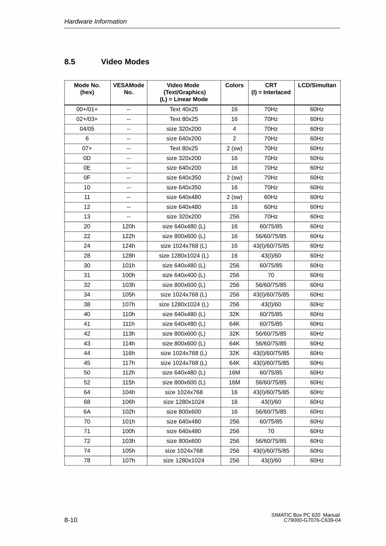
Hardware Information
8-10SIMATIC Box PC 620 Manual
C79000-G7076-C639-04
8.5 Video Modes
Mode No.(hex)
VESAModeNo.
Video Mode (Text/Graphics)
(L) = Linear Mode
Colors CRT(I) = Interlaced
LCD/Simultan
00+/01+ -- Text 40x25 16 70Hz 60Hz
02+/03+ -- Text 80x25 16 70Hz 60Hz
04/05 -- size 320x200 4 70Hz 60Hz
6 -- size 640x200 2 70Hz 60Hz
07+ -- Text 80x25 2 (sw) 70Hz 60Hz
0D -- size 320x200 16 70Hz 60Hz
0E -- size 640x200 16 70Hz 60Hz
0F -- size 640x350 2 (sw) 70Hz 60Hz
10 -- size 640x350 16 70Hz 60Hz
11 -- size 640x480 2 (sw) 60Hz 60Hz
12 -- size 640x480 16 60Hz 60Hz
13 -- size 320x200 256 70Hz 60Hz
20 120h size 640x480 (L) 16 60/75/85 60Hz
22 122h size 800x600 (L) 16 56/60/75/85 60Hz
24 124h size 1024x768 (L) 16 43(I)/60/75/85 60Hz
28 128h size 1280x1024 (L) 16 43(I)/60 60Hz
30 101h size 640x480 (L) 256 60/75/85 60Hz
31 100h size 640x400 (L) 256 70 60Hz
32 103h size 800x600 (L) 256 56/60/75/85 60Hz
34 105h size 1024x768 (L) 256 43(I)/60/75/85 60Hz
38 107h size 1280x1024 (L) 256 43(I)/60 60Hz
40 110h size 640x480 (L) 32K 60/75/85 60Hz
41 111h size 640x480 (L) 64K 60/75/85 60Hz
42 113h size 800x600 (L) 32K 56/60/75/85 60Hz
43 114h size 800x600 (L) 64K 56/60/75/85 60Hz
44 116h size 1024x768 (L) 32K 43(I)/60/75/85 60Hz
45 117h size 1024x768 (L) 64K 43(I)/60/75/85 60Hz
50 112h size 640x480 (L) 16M 60/75/85 60Hz
52 115h size 800x600 (L) 16M 56/60/75/85 60Hz
64 104h size 1024x768 16 43(I)/60/75/85 60Hz
68 106h size 1280x1024 16 43(I)/60 60Hz
6A 102h size 800x600 16 56/60/75/85 60Hz
70 101h size 640x480 256 60/75/85 60Hz
71 100h size 640x480 256 70 60Hz
72 103h size 800x600 256 56/60/75/85 60Hz
74 105h size 1024x768 256 43(I)/60/75/85 60Hz
78 107h size 1280x1024 256 43(I)/60 60Hz
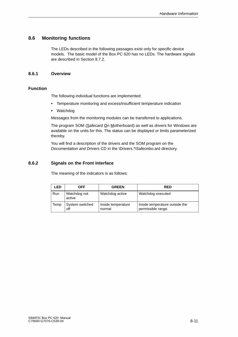
Hardware Information
8-11SIMATIC Box PC 620 ManualC79000-G7076-C639-04
8.6 Monitoring functions
The LEDs described in the following passages exist only for specific device models. The basic model of the Box PC 620 has no LEDs. The hardware signalsare described in Section 8.7.2.
8.6.1 Overview
Function
The following individual functions are implemented:
Temperature monitoring and excess/insufficient temperature indication
Watchdog
Messages from the monitoring modules can be transferred to applications.
The program SOM (Safecard On Motherboard) as well as drivers for Windows areavailable on the units for this. The status can be displayed or limits parameterizedthereby.
You will find a description of the drivers and the SOM program on theDocumentation and Drivers CD in the \Drivers.*\Safeonbo.ard directory.
8.6.2 Signals on the Front Interface
The meaning of the indicators is as follows:
LED OFF GREEN RED
Run Watchdog not active
Watchdog active Watchdog executed
Temp System switchedoff
Inside temperaturenormal
Inside temperature outside thepermissible range.

Hardware Information
8-12SIMATIC Box PC 620 Manual
C79000-G7076-C639-04
8.6.3 Temperature Monitoring/Indication
Temperature Monitoring
The temperature is measured by means of three temperature sensors. One sensormonitors the processor temperature, the second the temperature in the area of theprocessor module and the expansion cards and the third the temperature in thearea of the power supply unit.
If the temperature near the power supply exceeds 45oC (fixed value), the fan isset to maximum rpms. To activate this feature, the setting “Fan Control” has tobe turned on in the Setup menu (Sec. 6.1.4).
If the temperature exceeds one of the three temperature values of the set thres-holds, a temperature error is registered with the following effects:
Reaction Option
Temp LED from GREEN to RED always
Fan goes to maximum rpms. always
The processor speed is reduced 1 always
Initiate IRQ adjustable
Temperature errors do not occur during the normal approved use of the device. If atemperature error occurs, check the following possible causes:
Are the ventilation slots blocked?
Is the fan working?
Is the ambient temperature higher than the allowed value?
Has the total capacity for the power supply been exceeded?
The temperature error remains saved until the temperature thresholds are againexceeded and are reset by one of the following measures:
Acknowledge the error message via the SOM program
Restarting the device.
1 The lower processor speed can affect how programs run.

Hardware Information
8-13SIMATIC Box PC 620 ManualC79000-G7076-C639-04
8.6.4 Watchdog (WD)
Function
The watchdog monitors the execution of a program. The purpose of the WD is tonotify the user of a program crash through various reactions.
The watchdog is idle when the PC is switched on or after a HW-RESET(cold start),i.e. no reaction of the WD will be triggered and the RUN LED is switched off. If thewatchdog is activated (by driver or SOM program) the Run LED is green.
WD Reactions
If the WD is not triggered again within the set time (by driver or SOM program), thefollowing reactions are initiated:
Reaction Option
RUN LED switches from green to red always
Acknowledge WD always
Initiate reset of the PC adjustable
Shut down IRQ on the PC adjustable
SOM application is displayed adjustable
The reactions which are to be triggered can be parameterized by driver orSOM program.
WD Monitoring Times TWD
The monitoring times are adjustable in increments of one second in a range from3 to 255 seconds.
Note
If the watchdog time is changed after the watchdog was activated (i.e. while thewatchdog is running), the watchdog is retriggered!
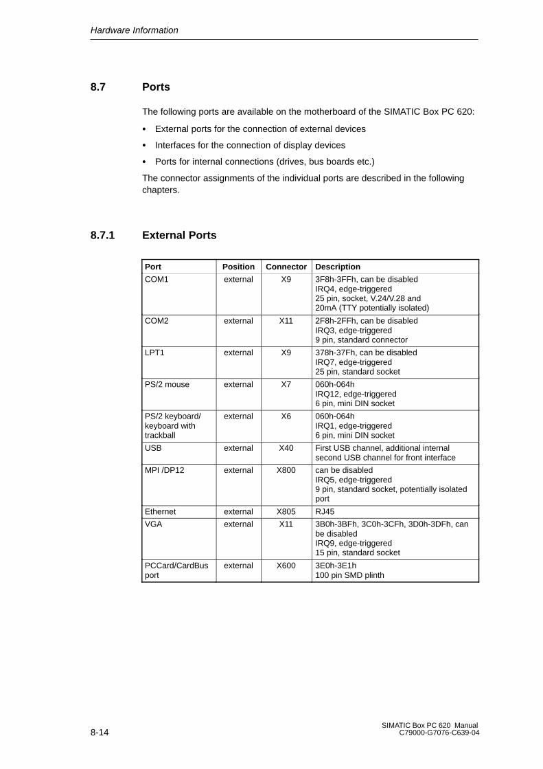
Hardware Information
8-14SIMATIC Box PC 620 Manual
C79000-G7076-C639-04
8.7 Ports
The following ports are available on the motherboard of the SIMATIC Box PC 620:
External ports for the connection of external devices
Interfaces for the connection of display devices
Ports for internal connections (drives, bus boards etc.)
The connector assignments of the individual ports are described in the followingchapters.
8.7.1 External Ports
Port Position Connector Description
COM1 external X9 3F8h-3FFh, can be disabledIRQ4, edge-triggered25 pin, socket, V.24/V.28 and20mA (TTY potentially isolated)
COM2 external X11 2F8h-2FFh, can be disabled IRQ3, edge-triggered9 pin, standard connector
LPT1 external X9 378h-37Fh, can be disabledIRQ7, edge-triggered25 pin, standard socket
PS/2 mouse external X7 060h-064hIRQ12, edge-triggered6 pin, mini DIN socket
PS/2 keyboard/keyboard withtrackball
external X6 060h-064hIRQ1, edge-triggered6 pin, mini DIN socket
USB external X40 First USB channel, additional internalsecond USB channel for front interface
MPI /DP12 external X800 can be disabledIRQ5, edge-triggered9 pin, standard socket, potentially isolatedport
Ethernet external X805 RJ45
VGA external X11 3B0h-3BFh, 3C0h-3CFh, 3D0h-3DFh, canbe disabledIRQ9, edge-triggered15 pin, standard socket
PCCard/CardBusport
external X600 3E0h-3E1h100 pin SMD plinth

Hardware Information
8-15SIMATIC Box PC 620 ManualC79000-G7076-C639-04
Serial Port COM1 (PLC/V.24/Modem) *
The serial port (COM 1) on the SIMATIC Box PC 620 has the following pinout:
1
13
14
25
Figure 8-1 COM 1 Serial Port (Socket Connector)
Pin No. Designation Description Input /Output
2 TxD (D1) Serial transmit data Output
3 RxD (D2) Serial receive data Input
4 RTS (S2) Request to send Output
5 CTS (M2) Clear to send Input
6 DSR (M1) Data set ready Input
7 GND (E2) Functional ground(reference potential)
-
8 DCD (M5) Data carrier detect Input
9 +TTY RxD TTY receive Input
10 -TTY RxD TTY receive Input
18 +TTY TxD TTY send Output
19 +20mA Isolated current source -
20 DTR (S1) Data terminal ready Output
21 -TTY TxD TTY send Output
22 RI (M3) Incoming call Input
1 - Shield -
11-17 - Unassigned -
23-25 - Unassigned -
* Without TTY for the basic variant of the Box PC
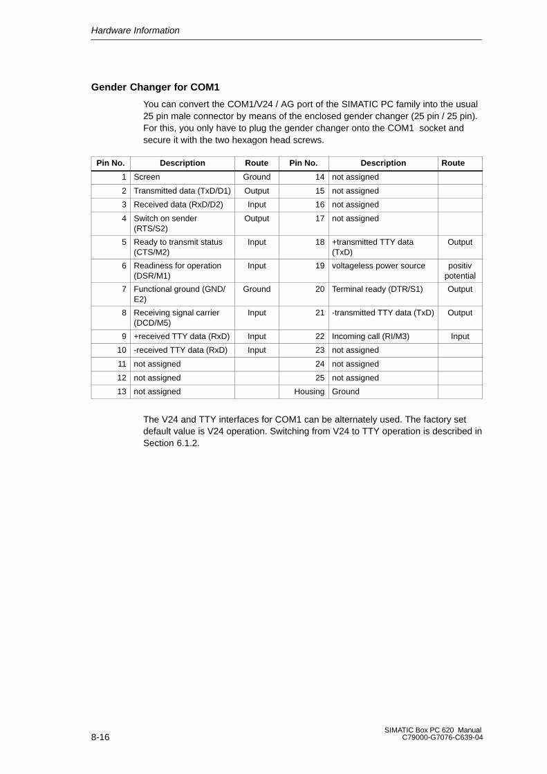
Hardware Information
8-16SIMATIC Box PC 620 Manual
C79000-G7076-C639-04
Gender Changer for COM1
You can convert the COM1/V24 / AG port of the SIMATIC PC family into the usual25 pin male connector by means of the enclosed gender changer (25 pin / 25 pin).For this, you only have to plug the gender changer onto the COM1 socket andsecure it with the two hexagon head screws.
Pin No. Description Route Pin No. Description Route
1 Screen Ground 14 not assigned
2 Transmitted data (TxD/D1) Output 15 not assigned
3 Received data (RxD/D2) Input 16 not assigned
4 Switch on sender (RTS/S2)
Output 17 not assigned
5 Ready to transmit status(CTS/M2)
Input 18 +transmitted TTY data(TxD)
Output
6 Readiness for operation(DSR/M1)
Input 19 voltageless power source positivpotential
7 Functional ground (GND/E2)
Ground 20 Terminal ready (DTR/S1) Output
8 Receiving signal carrier(DCD/M5)
Input 21 -transmitted TTY data (TxD) Output
9 +received TTY data (RxD) Input 22 Incoming call (RI/M3) Input
10 -received TTY data (RxD) Input 23 not assigned
11 not assigned 24 not assigned
12 not assigned 25 not assigned
13 not assigned Housing Ground
The V24 and TTY interfaces for COM1 can be alternately used. The factory setdefault value is V24 operation. Switching from V24 to TTY operation is described inSection 6.1.2.

Hardware Information
8-17SIMATIC Box PC 620 ManualC79000-G7076-C639-04
Serial Port COM2 (V24/Mouse)
The serial port (COM 2) on the SIMATIC Box PC 620 has the following pinout:
1
5
6
9
Figure 8-2 Serial Port COM 2 (Connector)
Pin No. Designation Description Input /Output
1 DCD (M5) Receiving signal level Input
2 RxD (D2) Received data Input
3 TxD (D1) Transmitted data Output
4 DTR (S1) Terminal ready Output
5 GND (E2) Functional ground -
6 DSR (M1) Readiness for operation Input
7 RTS (S2) Switch on transmitter Output
8 CTS (M2) Ready to transmit status Input
9 RI (M3) Incoming call Input
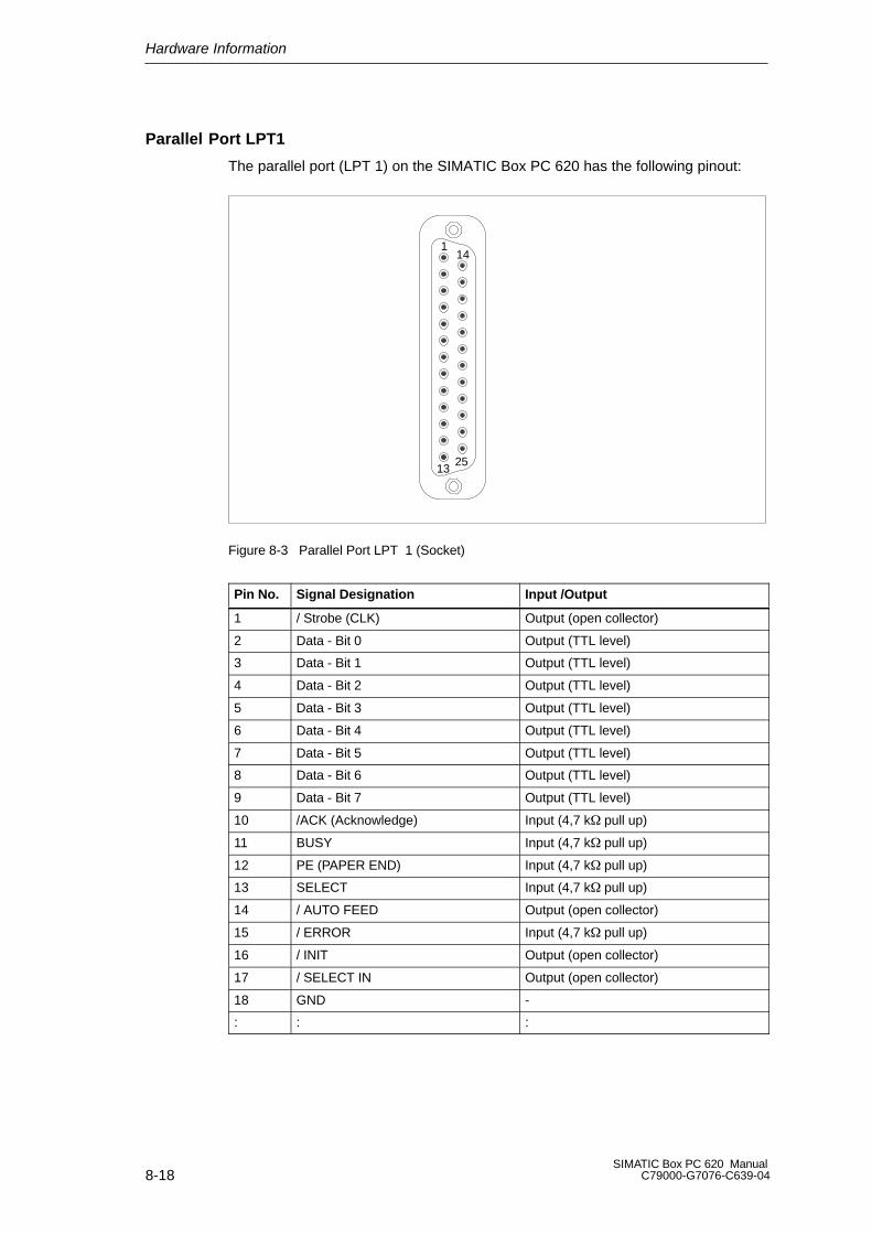
Hardware Information
8-18SIMATIC Box PC 620 Manual
C79000-G7076-C639-04
Parallel Port LPT1
The parallel port (LPT 1) on the SIMATIC Box PC 620 has the following pinout:
1
13
14
25
Figure 8-3 Parallel Port LPT 1 (Socket)
Pin No. Signal Designation Input /Output
1 / Strobe (CLK) Output (open collector)
2 Data - Bit 0 Output (TTL level)
3 Data - Bit 1 Output (TTL level)
4 Data - Bit 2 Output (TTL level)
5 Data - Bit 3 Output (TTL level)
6 Data - Bit 4 Output (TTL level)
7 Data - Bit 5 Output (TTL level)
8 Data - Bit 6 Output (TTL level)
9 Data - Bit 7 Output (TTL level)
10 /ACK (Acknowledge) Input (4,7 k pull up)
11 BUSY Input (4,7 k pull up)
12 PE (PAPER END) Input (4,7 k pull up)
13 SELECT Input (4,7 k pull up)
14 / AUTO FEED Output (open collector)
15 / ERROR Input (4,7 k pull up)
16 / INIT Output (open collector)
17 / SELECT IN Output (open collector)
18 GND -
: : :

Hardware Information
8-19SIMATIC Box PC 620 ManualC79000-G7076-C639-04
PS/2 Mouse Port
You can connect an external PS/2 mouse to your SIMATIC Box PC 620.The connector has the following pinout:
12
34
56
View of socket connector
Figure 8-4 Connector Pinout for a PS/2 Mouse
Pin No. Designation Input /Output
1 Data line Input/Output
2 Unassigned -
3 0 V -
4 Current limited 5V power supply Output
5 Clock line Input/Output
6 Unassigned -

Hardware Information
8-20SIMATIC Box PC 620 Manual
C79000-G7076-C639-04
PS/2 Keyboard with Trackball Port
You can connect an external keyboard to your SIMATIC Box PC 620.The connector has the following pinout:
View onto the socket
12
34
56
Figure 8-5 Connector Pinout for an External Keyboard Connecting Cable
Pin-No. Designation Input/Output
1 Data line, keyboard Input/output
2 Data line Input/output
3 0V -
4 Current limited 5V power supply Output
5 Clock line, keyboard Input/output
6 Clock line, trackball Input/output
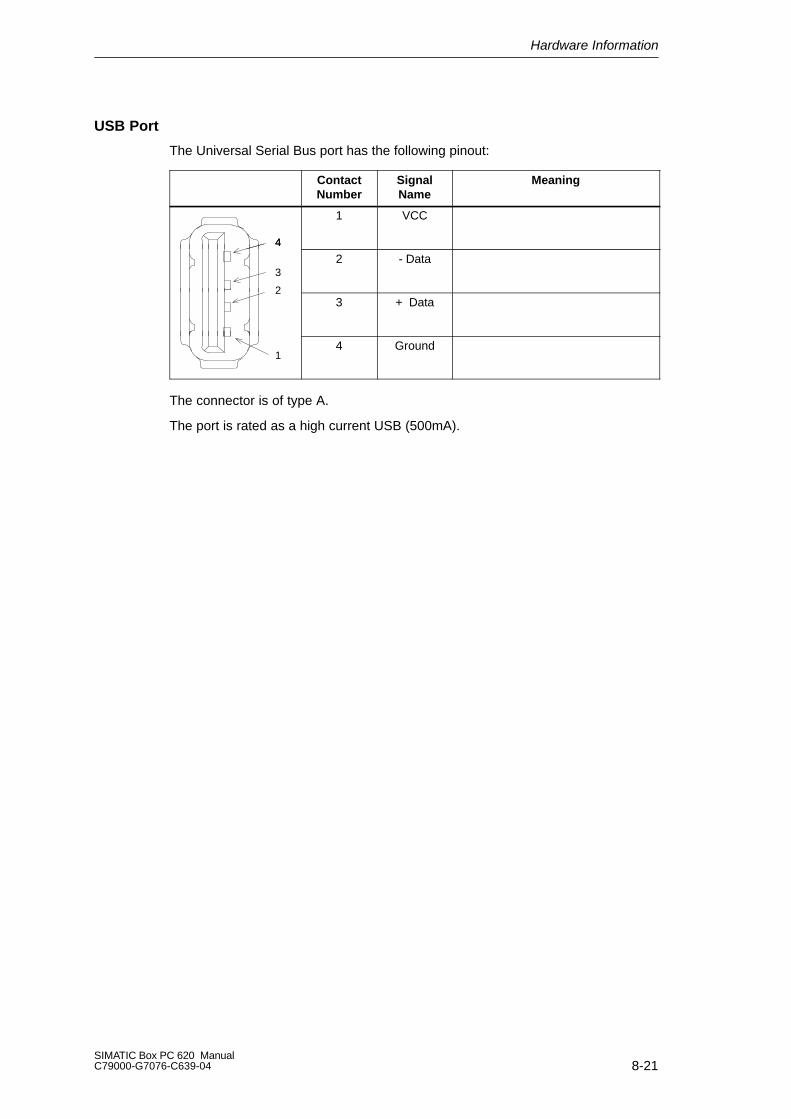
Hardware Information
8-21SIMATIC Box PC 620 ManualC79000-G7076-C639-04
USB Port
The Universal Serial Bus port has the following pinout:
ContactNumber
SignalName
Meaning
4
1 VCC
4
32 - Data
23 + Data
14 Ground
The connector is of type A.
The port is rated as a high current USB (500mA).

Hardware Information
8-22SIMATIC Box PC 620 Manual
C79000-G7076-C639-04
MPI/DP Socket Connector *
The MPI/DP socket connector on the SIMATIC box PC 620 has the followingpinout:
1
5
6
9
Figure 8-6 MPI/DP Socket Connector
Pin No. Designation Description Input/output
1 NC Pin 1 is not assigned -
2 NC Pin 2 is not assigned -
3 LTG_B Signal line B of MPI module Input/output
4 RTS_AS RTSAS, control signal for received datastream. The signal is “1” active when the pro-grammable controller is sending.
Input
5 M5EXT M5EXT return line (GND) of the 5 V power supply. The current load caused by an exter-nal user connected between P5EXT andM5EXT must not exceed max. 90 mA.
Output
6 P5 EXT P5EXT power supply (+5 V) of the 5 V powersupply. The current load caused by an exter-nal user connected between P5EXT andM5EXT must not exceed max. 90 mA.
Output
7 NC Pin 7 is not assigned -
8 LTG_A Signal line A of the MPI module Input/output
9 RTS_PG RTS output signal of the MPI module. The control signal is “1” when the programming device is sending.
Output
Screen on connector casing
* Not available for the basic variant of the Box PC
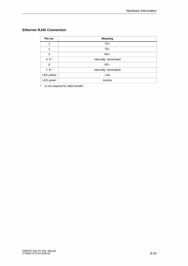
Hardware Information
8-23SIMATIC Box PC 620 ManualC79000-G7076-C639-04
Ethernet RJ45 Connection
Pin no. Meaning
1 TD+
2 TD–
3 RD+
4, 5 * internally terminated
6 RD–
7, 8 * internally terminated
LED yellow Link
LED green Activity
* is not required for data transfer
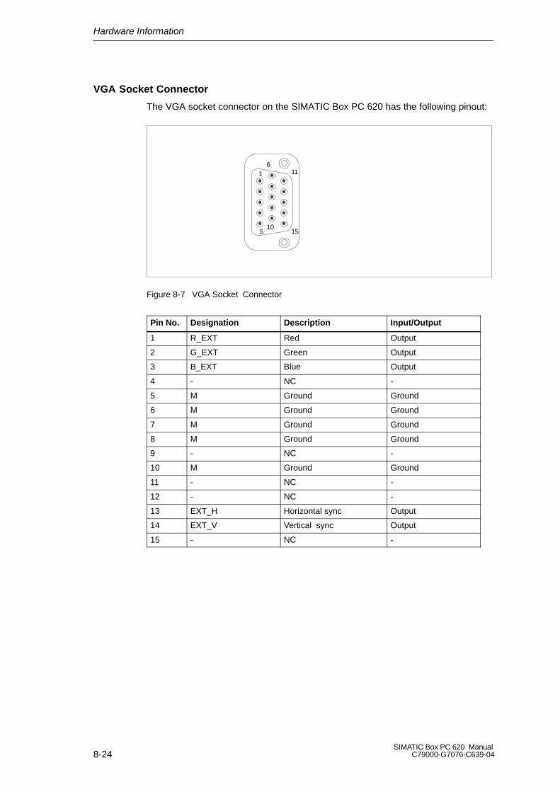
Hardware Information
8-24SIMATIC Box PC 620 Manual
C79000-G7076-C639-04
VGA Socket Connector
The VGA socket connector on the SIMATIC Box PC 620 has the following pinout:
1
5
6
10
11
15
Figure 8-7 VGA Socket Connector
Pin No. Designation Description Input/Output
1 R_EXT Red Output
2 G_EXT Green Output
3 B_EXT Blue Output
4 - NC -
5 M Ground Ground
6 M Ground Ground
7 M Ground Ground
8 M Ground Ground
9 - NC -
10 M Ground Ground
11 - NC -
12 - NC -
13 EXT_H Horizontal sync Output
14 EXT_V Vertical sync Output
15 - NC -
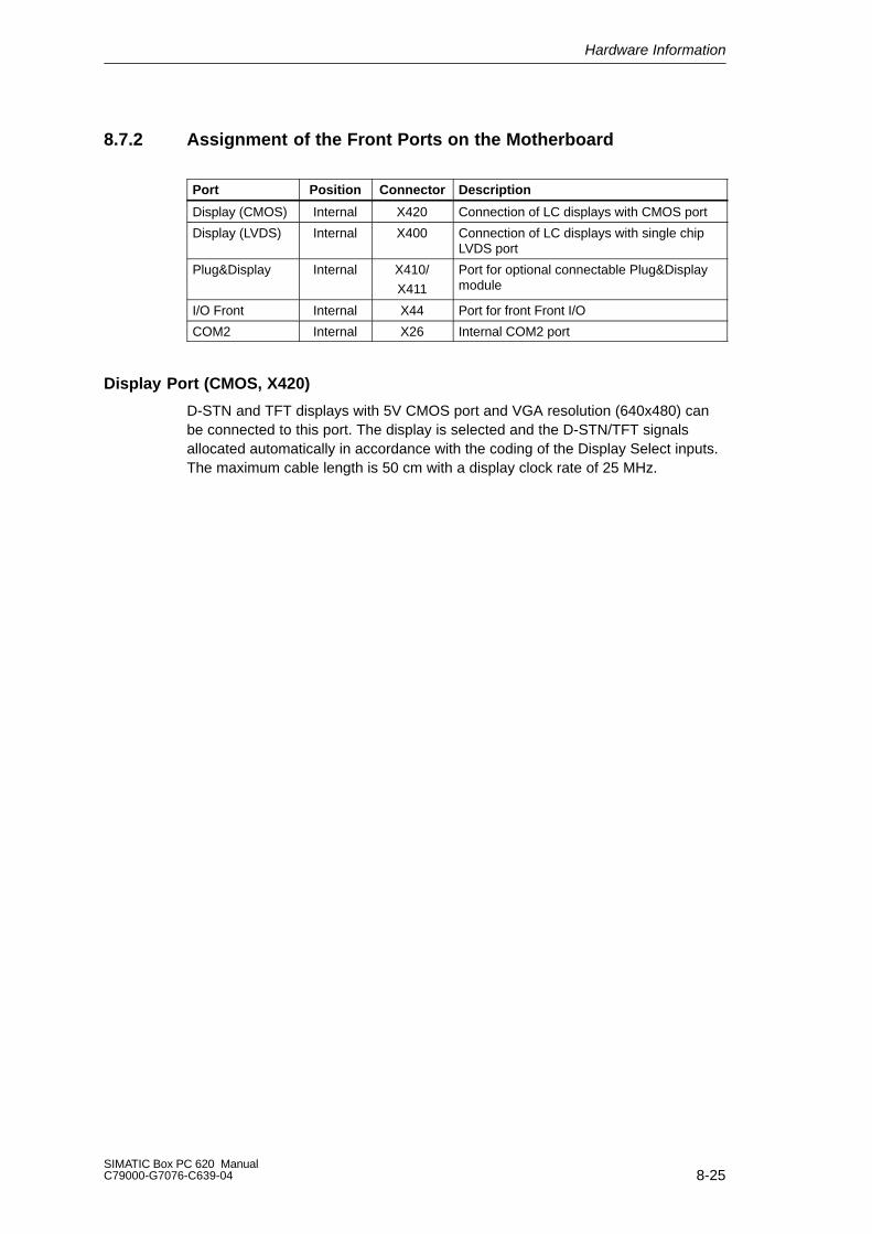
Hardware Information
8-25SIMATIC Box PC 620 ManualC79000-G7076-C639-04
8.7.2 Assignment of the Front Ports on the Motherboard
Port Position Connector Description
Display (CMOS) Internal X420 Connection of LC displays with CMOS port
Display (LVDS) Internal X400 Connection of LC displays with single chipLVDS port
Plug&Display Internal X410/
X411
Port for optional connectable Plug&Displaymodule
I/O Front Internal X44 Port for front Front I/O
COM2 Internal X26 Internal COM2 port
Display Port (CMOS, X420)
D-STN and TFT displays with 5V CMOS port and VGA resolution (640x480) canbe connected to this port. The display is selected and the D-STN/TFT signalsallocated automatically in accordance with the coding of the Display Select inputs.The maximum cable length is 50 cm with a display clock rate of 25 MHz.
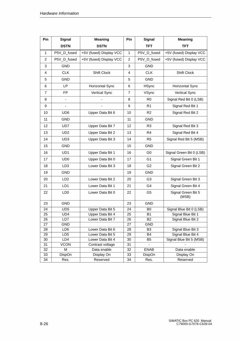
Hardware Information
8-26SIMATIC Box PC 620 Manual
C79000-G7076-C639-04
Pin Signal Meaning Pin Signal Meaning
DSTN DSTN TFT TFT
1 P5V_D_fused +5V (fused) Display VCC 1 P5V_D_fused +5V (fused) Display VCC
2 P5V_D_fused +5V (fused) Display VCC 2 P5V_D_fused +5V (fused) Display VCC
3 GND 3 GND
4 CLK Shift Clock 4 CLK Shift Clock
5 GND 5 GND
6 LP Horizontal Sync 6 HSync Horizontal Sync
7 FP Vertical Sync 7 VSync Vertical Sync
8 - - 8 R0 Signal Red Bit 0 (LSB)
9 - - 9 R1 Signal Red Bit 1
10 UD6 Upper Data Bit 6 10 R2 Signal Red Bit 2
11 GND 11 GND
12 UD7 Upper Data Bit 7 12 R3 Signal Red Bit 3
13 UD2 Upper Data Bit 2 13 R4 Signal Red Bit 4
14 UD3 Upper Data Bit 3 14 R5 Signal Red Bit 5 (MSB)
15 GND 15 GND
16 UD1 Upper Data Bit 1 16 G0 Signal Green Bit 0 (LSB)
17 UD0 Upper Data Bit 0 17 G1 Signal Green Bit 1
18 LD3 Lower Data Bit 3 18 G2 Signal Green Bit 2
19 GND 19 GND
20 LD2 Lower Data Bit 2 20 G3 Signal Green Bit 3
21 LD1 Lower Data Bit 1 21 G4 Signal Green Bit 4
22 LD0 Lower Data Bit 0 22 G5 Signal Green Bit 5(MSB)
23 GND 23 GND
24 UD5 Upper Data Bit 5 24 B0 Signal Blue Bit 0 (LSB)25 UD4 Upper Data Bit 4 25 B1 Signal Blue Bit 126 LD7 Lower Data Bit 7 26 B2 Signal Blue Bit 227 GND 27 GND28 LD6 Lower Data Bit 6 28 B3 Signal Blue Bit 329 LD5 Lower Data Bit 5 29 B4 Signal Blue Bit 430 LD4 Lower Data Bit 4 30 B5 Signal Blue Bit 5 (MSB)31 VCON Contrast voltage 31 - -32 M Data enable 32 ENAB Data enable33 DispOn Display On 33 DispOn Display On34 Res. Reserved 34 Res. Reserved

Hardware Information
8-27SIMATIC Box PC 620 ManualC79000-G7076-C639-04
Display Port (LVDS), X400
TFT displays with an LVDS port can be connected to this port. The connection of18 bit displays up to a resolution of 1024x768 pixels is possible. The permissibledisplay clock rate is 20MHz to 66Mhz. The display is selected automatically inaccordance with the coding of the Select Inputs display. The display supplyvoltages (3.3V and 5V) are connected via the graphic controller, dependent on the-requirements of the connected displays. The maximum cable length is 50cm with atransmission rate of 455MHz. Special cable properties are to be considered for thepair of differential cables in accordance with the LVDS specification.
Pin No. Signal Meaning
1 P5V_D_fused +5V (fused) Display VCC
2 P5V_D_fused +5V (fused) Display VCC
3 RXIN0– LVDS Input signal Bit 0 (-)
4 RXIN0+ LVDS Input signal Bit 0 (+)
5 P3V3_D_fused +3,3V (fused) Display VCC
6 P3V3_D_fused +3,3V (fused) Display VCC
7 RXIN1– LVDS Input signal Bit 1 (-)
8 RXIN1+ LVDS Input signal Bit 1 (+)
9 GND
10 GND
11 RXIN2- LVDS Input signal Bit 2 (-)
12 RXIN2+ LVDS Input signal Bit 2 (+)
13 GND
14 GND
15 RXCLKIN- LVDS clock pulse (-)
16 RXCLKIN+ LVDS clock pulse (+)
17 GND
18 GND
19 Reserved
20 Reserved

Hardware Information
8-28SIMATIC Box PC 620 Manual
C79000-G7076-C639-04
Allocation of the Display to Display Select Pins
The automatic configuration of one of 15 possible displays is effected via theDisplay Select Inputs. The Display Select inputs are fitted with Pull-Up resistors,i.e. if these inputs are not connected, they have a high level. In order to generate alow level, the input must be connected to GND.
Nr. LCD_SEL3 LCD_SEL2 LCD_SEL1 LCD_SEL0 Display Type
0 low low low low reserved
1 low low low high reserved
2 low low high low 640 x 480 (VGA), D-STN, 16 bit
3 low low high high reserved
4 low high low low 640 x 480 (VGA), TFT, 18 bit
5 low high low high reserved
6 low high high low 1024 x 768 (XGA), TFT, 18 bit
7 low high high high 800 x 600 (SVGA), TFT, 18 bit
8 high low low low reserved
9 high low low high reserved
10 high low high low reserved
11 high low high high reserved
12 high high low low reserved
13 high high low high reserved
14 high high high low reserved
15 high high high high No display / DDC selecteddisplay
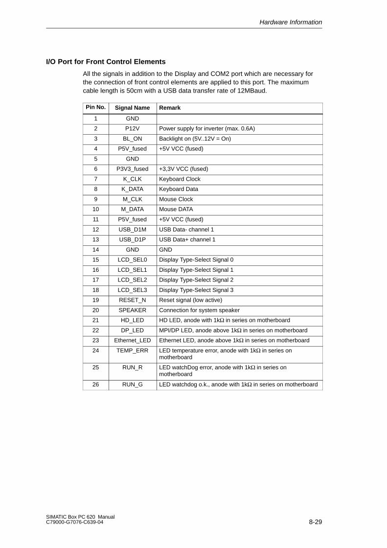
Hardware Information
8-29SIMATIC Box PC 620 ManualC79000-G7076-C639-04
I/O Port for Front Control Elements
All the signals in addition to the Display and COM2 port which are necessary forthe connection of front control elements are applied to this port. The maximumcable length is 50cm with a USB data transfer rate of 12MBaud.
Pin No. Signal Name Remark
1 GND
2 P12V Power supply for inverter (max. 0.6A)
3 BL_ON Backlight on (5V..12V = On)
4 P5V_fused +5V VCC (fused)
5 GND
6 P3V3_fused +3,3V VCC (fused)
7 K_CLK Keyboard Clock
8 K_DATA Keyboard Data
9 M_CLK Mouse Clock
10 M_DATA Mouse DATA
11 P5V_fused +5V VCC (fused)
12 USB_D1M USB Data- channel 1
13 USB_D1P USB Data+ channel 1
14 GND GND
15 LCD_SEL0 Display Type-Select Signal 0
16 LCD_SEL1 Display Type-Select Signal 1
17 LCD_SEL2 Display Type-Select Signal 2
18 LCD_SEL3 Display Type-Select Signal 3
19 RESET_N Reset signal (low active)
20 SPEAKER Connection for system speaker
21 HD_LED HD LED, anode with 1kΩ in series on motherboard
22 DP_LED MPI/DP LED, anode above 1kΩ in series on motherboard
23 Ethernet_LED Ethernet LED, anode above 1kΩ in series on motherboard
24 TEMP_ERR LED temperature error, anode with 1kΩ in series onmotherboard
25 RUN_R LED watchDog error, anode with 1kΩ in series onmotherboard
26 RUN_G LED watchdog o.k., anode with 1kΩ in series on motherboard
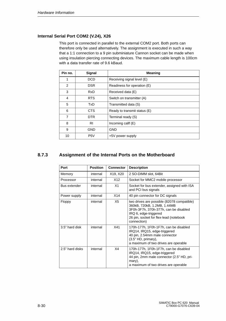
Hardware Information
8-30SIMATIC Box PC 620 Manual
C79000-G7076-C639-04
Internal Serial Port COM2 (V.24), X26
This port is connected in parallel to the external COM2 port. Both ports cantherefore only be used alternatively. The assignment is executed in such a waythat a 1:1 connection to a 9 pin subminiature Cannon socket can be made whenusing insulation piercing connecting devices. The maximum cable length is 100cmwith a data transfer rate of 9.6 kBaud.
Pin no. Signal Meaning
1 DCD Receiving signal level (E)
2 DSR Readiness for operation (E)
3 RxD Received data (E)
4 RTS Switch on transmitter (A)
5 TxD Transmitted data (S)
6 CTS Ready to transmit status (E)
7 DTR Terminal ready (S)
8 RI Incoming callf (E)
9 GND GND
10 P5V +5V power supply
8.7.3 Assignment of the Internal Ports on the Motherboard
Port Position Connector Description
Memory internal X19, X20 2 SO-DIMM slot, 64Bit
Processor internal X12 Socket for MMC2 mobile processor
Bus extender internal X1 Socket for bus extender, assigned with ISAand PCI bus signals
Power supply internal X14 40 pin connector for DC signals
Floppy internal X5 two drives are possible (82078 compatible)360kB, 720kB, 1.2MB, 1.44MB3F0h-3F7h, 370h-377h, can be disabledIRQ 6, edge-triggered26 pin, socket for flex-lead (notebookconnection)
3.5” hard disk internal X41 170h-177h, 1F0h-1F7h, can be disabledIRQ14, IRQ15, edge-triggered40 pin, 2.54mm male connector(3.5” HD, primary),a maximum of two drives are operable
2.5” hard disks internal X4 170h-177h, 1F0h-1F7h, can be disabledIRQ14, IRQ15, edge-triggered44 pin, 2mm male connector (2.5” HD, pri-mary),a maximum of two drives are operable
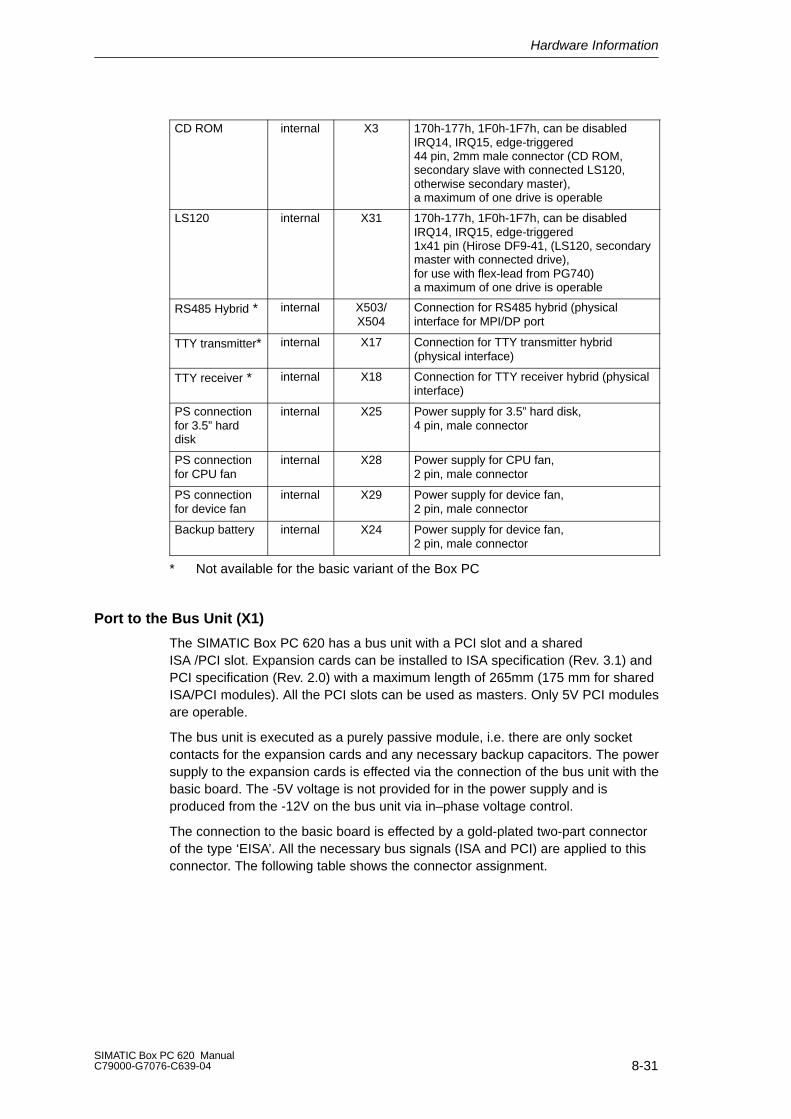
Hardware Information
8-31SIMATIC Box PC 620 ManualC79000-G7076-C639-04
CD ROM internal X3 170h-177h, 1F0h-1F7h, can be disabledIRQ14, IRQ15, edge-triggered44 pin, 2mm male connector (CD ROM,secondary slave with connected LS120,otherwise secondary master),a maximum of one drive is operable
LS120 internal X31 170h-177h, 1F0h-1F7h, can be disabledIRQ14, IRQ15, edge-triggered1x41 pin (Hirose DF9-41, (LS120, secondarymaster with connected drive),for use with flex-lead from PG740)a maximum of one drive is operable
RS485 Hybrid * internal X503/X504
Connection for RS485 hybrid (physicalinterface for MPI/DP port
TTY transmitter* internal X17 Connection for TTY transmitter hybrid(physical interface)
TTY receiver * internal X18 Connection for TTY receiver hybrid (physicalinterface)
PS connectionfor 3.5” harddisk
internal X25 Power supply for 3.5” hard disk,4 pin, male connector
PS connectionfor CPU fan
internal X28 Power supply for CPU fan,2 pin, male connector
PS connectionfor device fan
internal X29 Power supply for device fan,2 pin, male connector
Backup battery internal X24 Power supply for device fan,2 pin, male connector
* Not available for the basic variant of the Box PC
Port to the Bus Unit (X1)
The SIMATIC Box PC 620 has a bus unit with a PCI slot and a sharedISA /PCI slot. Expansion cards can be installed to ISA specification (Rev. 3.1) andPCI specification (Rev. 2.0) with a maximum length of 265mm (175 mm for sharedISA/PCI modules). All the PCI slots can be used as masters. Only 5V PCI modulesare operable.
The bus unit is executed as a purely passive module, i.e. there are only socketcontacts for the expansion cards and any necessary backup capacitors. The powersupply to the expansion cards is effected via the connection of the bus unit with thebasic board. The -5V voltage is not provided for in the power supply and isproduced from the -12V on the bus unit via in–phase voltage control.
The connection to the basic board is effected by a gold-plated two-part connectorof the type ‘EISA’. All the necessary bus signals (ISA and PCI) are applied to thisconnector. The following table shows the connector assignment.
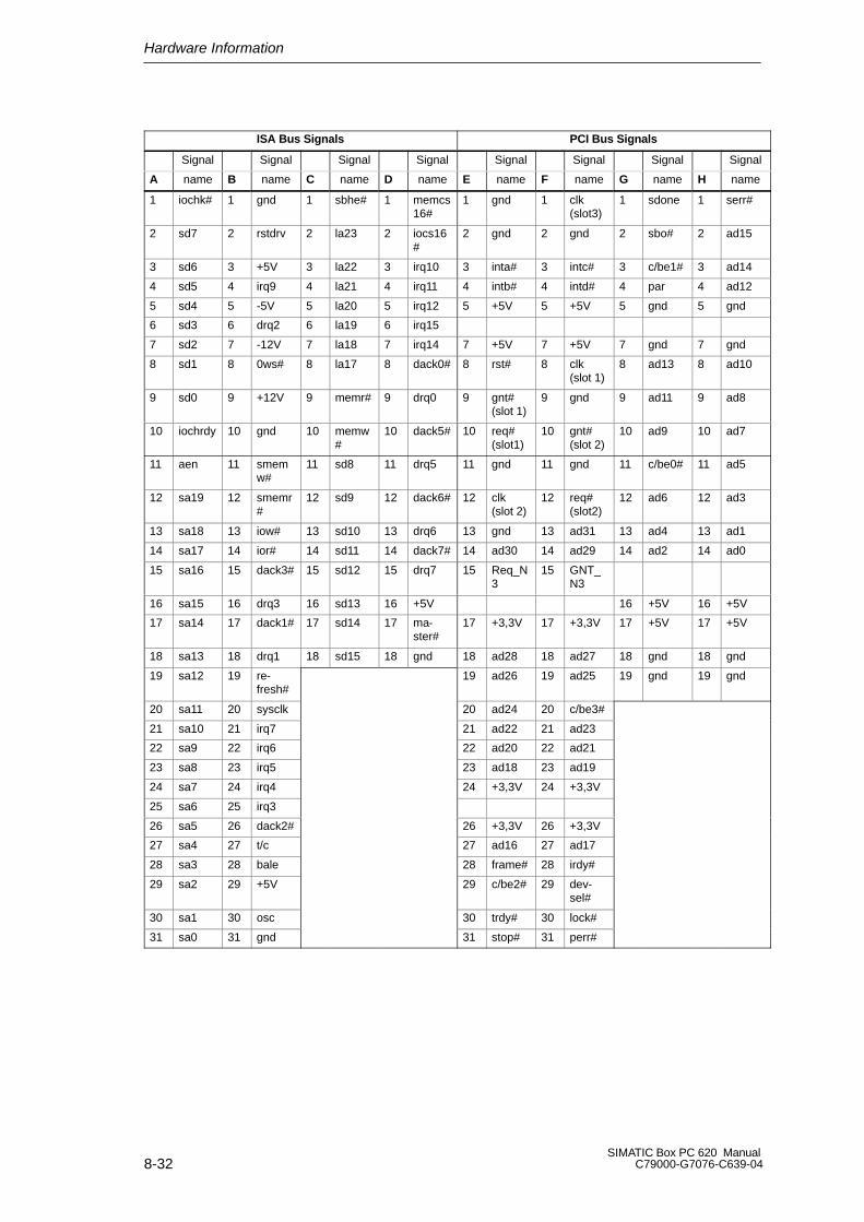
Hardware Information
8-32SIMATIC Box PC 620 Manual
C79000-G7076-C639-04
ISA Bus Signals PCI Bus Signals
Signal Signal Signal Signal Signal Signal Signal Signal
A name B name C name D name E name F name G name H name
1 iochk# 1 gnd 1 sbhe# 1 memcs16#
1 gnd 1 clk(slot3)
1 sdone 1 serr#
2 sd7 2 rstdrv 2 la23 2 iocs16#
2 gnd 2 gnd 2 sbo# 2 ad15
3 sd6 3 +5V 3 la22 3 irq10 3 inta# 3 intc# 3 c/be1# 3 ad14
4 sd5 4 irq9 4 la21 4 irq11 4 intb# 4 intd# 4 par 4 ad12
5 sd4 5 -5V 5 la20 5 irq12 5 +5V 5 +5V 5 gnd 5 gnd
6 sd3 6 drq2 6 la19 6 irq15
7 sd2 7 -12V 7 la18 7 irq14 7 +5V 7 +5V 7 gnd 7 gnd
8 sd1 8 0ws# 8 la17 8 dack0# 8 rst# 8 clk(slot 1)
8 ad13 8 ad10
9 sd0 9 +12V 9 memr# 9 drq0 9 gnt#(slot 1)
9 gnd 9 ad11 9 ad8
10 iochrdy 10 gnd 10 memw#
10 dack5# 10 req#(slot1)
10 gnt#(slot 2)
10 ad9 10 ad7
11 aen 11 smemw#
11 sd8 11 drq5 11 gnd 11 gnd 11 c/be0# 11 ad5
12 sa19 12 smemr#
12 sd9 12 dack6# 12 clk(slot 2)
12 req#(slot2)
12 ad6 12 ad3
13 sa18 13 iow# 13 sd10 13 drq6 13 gnd 13 ad31 13 ad4 13 ad1
14 sa17 14 ior# 14 sd11 14 dack7# 14 ad30 14 ad29 14 ad2 14 ad0
15 sa16 15 dack3# 15 sd12 15 drq7 15 Req_N3
15 GNT_N3
16 sa15 16 drq3 16 sd13 16 +5V 16 +5V 16 +5V
17 sa14 17 dack1# 17 sd14 17 ma-ster#
17 +3,3V 17 +3,3V 17 +5V 17 +5V
18 sa13 18 drq1 18 sd15 18 gnd 18 ad28 18 ad27 18 gnd 18 gnd
19 sa12 19 re-fresh#
19 ad26 19 ad25 19 gnd 19 gnd
20 sa11 20 sysclk 20 ad24 20 c/be3#
21 sa10 21 irq7 21 ad22 21 ad23
22 sa9 22 irq6 22 ad20 22 ad21
23 sa8 23 irq5 23 ad18 23 ad19
24 sa7 24 irq4 24 +3,3V 24 +3,3V
25 sa6 25 irq3
26 sa5 26 dack2# 26 +3,3V 26 +3,3V
27 sa4 27 t/c 27 ad16 27 ad17
28 sa3 28 bale 28 frame# 28 irdy#
29 sa2 29 +5V 29 c/be2# 29 dev-sel#
30 sa1 30 osc 30 trdy# 30 lock#
31 sa0 31 gnd 31 stop# 31 perr#
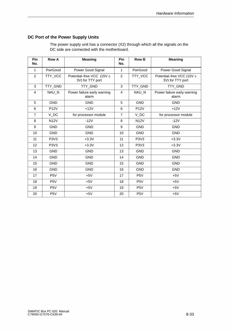
Hardware Information
8-33SIMATIC Box PC 620 ManualC79000-G7076-C639-04
DC Port of the Power Supply Units
The power supply unit has a connector (X2) through which all the signals on theDC side are connected with the motherboard.
PinNo.
Row A Meaning PinNo.
Row B Meaning
1 PwrGood Power Good Signal 1 PwrGood Power Good Signal
2 TTY_VCC Potential–free VCC (15V ±3V) for TTY port
2 TTY_VCC Potential–free VCC (15V ±3V) for TTY port
3 TTY_GND TTY_GND 3 TTY_GND TTY_GND
4 NAU_N Power failure early warningalarm
4 NAU_N Power failure early warningalarm
5 GND GND 5 GND GND
6 P12V +12V 6 P12V +12V
7 V_DC for processor module 7 V_DC for processor module
8 N12V -12V 8 N12V -12V
9 GND GND 9 GND GND
10 GND GND 10 GND GND
11 P3V3 +3.3V 11 P3V3 +3.3V
12 P3V3 +3.3V 12 P3V3 +3.3V
13 GND GND 13 GND GND
14 GND GND 14 GND GND
15 GND GND 15 GND GND
16 GND GND 16 GND GND
17 P5V +5V 17 P5V +5V
18 P5V +5V 18 P5V +5V
19 P5V +5V 19 P5V +5V
20 P5V +5V 20 P5V +5V

Hardware Information
8-34SIMATIC Box PC 620 Manual
C79000-G7076-C639-04
Port to the Floppy Disk Drive (X5)
This port is intended for the connection of a notebook floppy disk drive. Themaximum connection length of the data cable may not exceed 40cm.
Pin no. Signal Name Remark
1 P5V
2 INDEX_N
3 P5V
4 DS_N0
5 P5V
6 DCHG_N
7 n.c.
8 n.c.
9 HDOUT
10 MOT_N0
11 HDIN
12 DIR_SL_N
13 n.c.
14 STEP_N
15 GND
16 WR_DAT_N
17 GND
18 WR_GAT_N
19 EDOUT
20 TRACK_N0
21 EDIN
22 WR_PRT_N
23 GND
24 RD_DAT_N
25 GND
26 SIDE_1_N
Assignment of the IDE Ports (X3, X4, X41)
The primary IDE port is intended for the alternative installation of2.5” and 3.5” hard disks. 3.5” drives are connected via a 40 pin 2.54mm latchingconnector, 2.5” drives via a 44 pin 2mm latching connector. The two connectorsare connected in parallel. The secondary IDE port is intended for the optionalconnection of a CD ROM and / or an LS 120 drive. It is adaptable via a 44 pin2mm latching connector. The maximum connection length of the data cables maynot exceed 40cm.
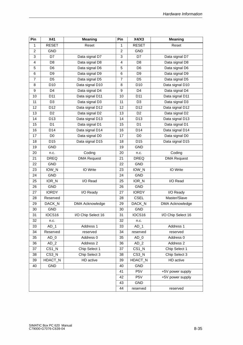
Hardware Information
8-35SIMATIC Box PC 620 ManualC79000-G7076-C639-04
Pin X41 Meaning Pin X4/X3 Meaning
1 RESET Reset 1 RESET Reset
2 GND 2 GND
3 D7 Data signal D7 3 D7 Data signal D7
4 D8 Data signal D8 4 D8 Data signal D8
5 D6 Data signal D6 5 D6 Data signal D6
6 D9 Data signal D9 6 D9 Data signal D9
7 D5 Data signal D5 7 D5 Data signal D5
8 D10 Data signal D10 8 D10 Data signal D10
9 D4 Data signal D4 9 D4 Data signal D4
10 D11 Data signal D11 10 D11 Data signal D11
11 D3 Data signal D3 11 D3 Data signal D3
12 D12 Data signal D12 12 D12 Data signal D12
13 D2 Data signal D2 13 D2 Data signal D2
14 D13 Data signal D13 14 D13 Data signal D13
15 D1 Data signal D1 15 D1 Data signal D1
16 D14 Data signal D14 16 D14 Data signal D14
17 D0 Data signal D0 17 D0 Data signal D0
18 D15 Data signal D15 18 D15 Data signal D15
19 GND 19 GND
20 n.c. Coding 20 n.c. Coding
21 DREQ DMA Request 21 DREQ DMA Request
22 GND 22 GND
23 IOW_N IO Write 23 IOW_N IO Write
24 GND 24 GND
25 IOR_N I/O Read 25 IOR_N I/O Read
26 GND 26 GND
27 IORDY I/O Ready 27 IORDY I/O Ready
28 Reserved 28 CSEL Master/Slave
29 DACK_N DMA Acknowledge 29 DACK_N DMA Acknowledge
30 GND 30 GND
31 IOCS16 I/O Chip Select 16 31 IOCS16 I/O Chip Select 16
32 n.c. 32 n.c.
33 AD_1 Address 1 33 AD_1 Address 1
34 Reserved reserved 34 reserved reserved
35 AD_0 Address 0 35 AD_0 Address 0
36 AD_2 Address 2 36 AD_2 Address 2
37 CS1_N Chip Select 1 37 CS1_N Chip Select 1
38 CS3_N Chip Select 3 38 CS3_N Chip Select 3
39 HDACT_N HD active 39 HDACT_N HD active
40 GND 40 GND
41 P5V +5V power supply
42 P5V +5V power supply
43 GND
44 reserved reserved
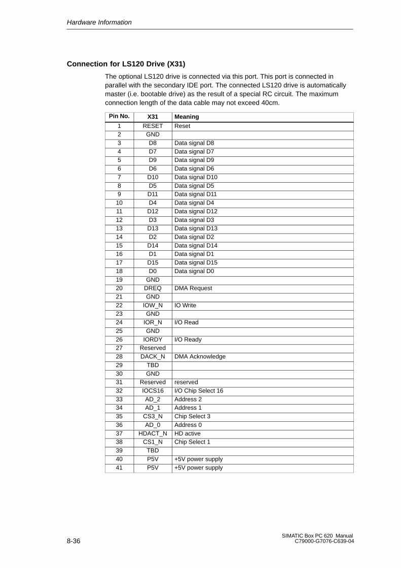
Hardware Information
8-36SIMATIC Box PC 620 Manual
C79000-G7076-C639-04
Connection for LS120 Drive (X31)
The optional LS120 drive is connected via this port. This port is connected inparallel with the secondary IDE port. The connected LS120 drive is automaticallymaster (i.e. bootable drive) as the result of a special RC circuit. The maximumconnection length of the data cable may not exceed 40cm.
Pin No. X31 Meaning
1 RESET Reset2 GND3 D8 Data signal D84 D7 Data signal D75 D9 Data signal D96 D6 Data signal D67 D10 Data signal D108 D5 Data signal D59 D11 Data signal D11
10 D4 Data signal D411 D12 Data signal D1212 D3 Data signal D313 D13 Data signal D1314 D2 Data signal D215 D14 Data signal D1416 D1 Data signal D117 D15 Data signal D1518 D0 Data signal D019 GND20 DREQ DMA Request21 GND22 IOW_N IO Write23 GND24 IOR_N I/O Read25 GND26 IORDY I/O Ready27 Reserved28 DACK_N DMA Acknowledge29 TBD30 GND31 Reserved reserved32 IOCS16 I/O Chip Select 1633 AD_2 Address 234 AD_1 Address 135 CS3_N Chip Select 336 AD_0 Address 037 HDACT_N HD active38 CS1_N Chip Select 139 TBD40 P5V +5V power supply41 P5V +5V power supply
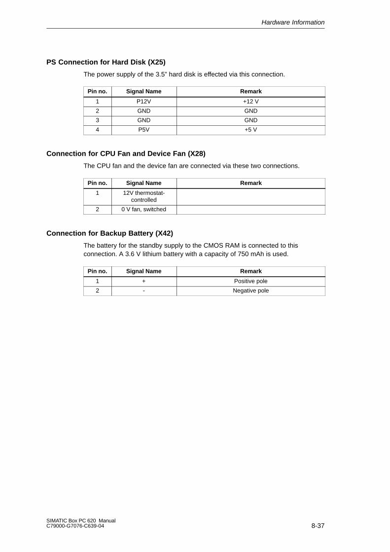
Hardware Information
8-37SIMATIC Box PC 620 ManualC79000-G7076-C639-04
PS Connection for Hard Disk (X25)
The power supply of the 3.5” hard disk is effected via this connection.
Pin no. Signal Name Remark
1 P12V +12 V
2 GND GND
3 GND GND
4 P5V +5 V
Connection for CPU Fan and Device Fan (X28)
The CPU fan and the device fan are connected via these two connections.
Pin no. Signal Name Remark
1 12V thermostat-controlled
2 0 V fan, switched
Connection for Backup Battery (X42)
The battery for the standby supply to the CMOS RAM is connected to thisconnection. A 3.6 V lithium battery with a capacity of 750 mAh is used.
Pin no. Signal Name Remark
1 + Positive pole
2 - Negative pole
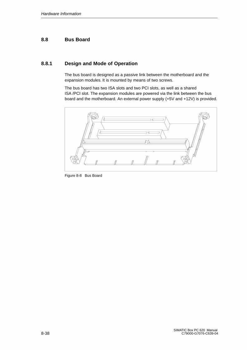
Hardware Information
8-38SIMATIC Box PC 620 Manual
C79000-G7076-C639-04
8.8 Bus Board
8.8.1 Design and Mode of Operation
The bus board is designed as a passive link between the motherboard and theexpansion modules. It is mounted by means of two screws.
The bus board has two ISA slots and two PCI slots, as well as a sharedISA /PCI slot. The expansion modules are powered via the link between the busboard and the motherboard. An external power supply (+5V and +12V) is provided.
Figure 8-8 Bus Board

Hardware Information
8-39SIMATIC Box PC 620 ManualC79000-G7076-C639-04
8.8.2 Interface to the Motherboard
The connection to the motherboard is established by a gold-colored EISA indirectconnector. All the required bus signals (ISA and PCI) are present on thisconnector. The following table shows the pin assignments.
ISA Bus Signals PCI Bus Signals
Signal Signal Signal Signal Signal Signal Signal Signal
A name B name C name D name E name F name G name H name
1 iochk# 1 gnd 1 sbhe# 1 memcs16#
1 gnd 1 clk(slot3)
1 sdone 1 serr#
2 sd7 2 rstdrv 2 la23 2 iocs16# 2 gnd 2 gnd 2 sbo# 2 ad153 sd6 3 +5V 3 la22 3 irq10 3 inta# 3 intc# 3 c/be1# 3 ad14
4 sd5 4 irq9 4 la21 4 irq11 4 intb# 4 intd# 4 par 4 ad12
5 sd4 5 -5V 5 la20 5 irq12 5 +5V 5 +5V 5 gnd 5 gnd
6 sd3 6 drq2 6 la19 6 irq157 sd2 7 -12V 7 la18 7 irq14 7 +5V 7 +5V 7 gnd 7 gnd
8 sd1 8 0ws# 8 la17 8 dack0# 8 rst# 8 clk (slot1)
8 ad13 8 ad10
9 sd0 9 +12V 9 memr# 9 drq0 9 gnt#(slot 1)
9 gnd 9 ad11 9 ad8
10 iochrdy 10 gnd 10
memw#
10 dack5# 10 req#(slot1)
10 gnt#(slot 2)
10
ad9 10 ad7
11 aen 11 smemw# 11
sd8 11 drq5 11 gnd 11 gnd 11
c/be0# 11 ad5
12 sa19 12 smemr# 12
sd9 12 dack6# 12 clk (slot2)
12 req#(slot2)
12
ad6 12 ad3
13 sa18 13 iow# 13
sd10 13 drq6 13 gnd 13 ad31 13
ad4 13 ad1
14 sa17 14 ior# 14
sd11 14 dack7# 14 ad30 14 ad29 14
ad2 14 ad0
15 sa16 15 dack3# 15
sd12 15 drq7 15 Req_N3 15 GNT_N3
16 sa15 16 drq3 16
sd13 16 +5V 16
+5V 16 +5V
17 sa14 17 dack1# 17
sd14 17 ma-ster#
17 +3,3V 17 +3,3V 17
+5V 17 +5V
18 sa13 18 drq1 18
sd15 18 gnd 18 ad28 18 ad27 18
gnd 18 gnd
19 sa12 19 refresh# 19 ad26 19 ad25 19
gnd 19 gnd
20 sa11 20 sysclk 20 ad24 20 c/be3#21 sa10 21 irq7 21 ad22 21 ad23
22 sa9 22 irq6 22 ad20 22 ad21
23 sa8 23 irq5 23 ad18 23 ad19
24 sa7 24 irq4 24 +3,3V 24 +3,3V25 sa6 25 irq3
26 sa5 26 dack2# 26 +3,3V 26 +3,3V
27 sa4 27 t/c 27 ad16 27 ad1728 sa3 28 bale 28 frame# 28 irdy#
29 sa2 29 +5V 29 c/be2# 29 devsel#
30 sa1 30 osc 30 trdy# 30 lock#
31 sa0 31 gnd 31 stop# 31 perr#

Hardware Information
8-40SIMATIC Box PC 620 Manual
C79000-G7076-C639-04
ISA Slot Pin Assignment
Pin Signal Name Type* Pin Signal Name Type
A1 –IOCHCK I B1 0 V GND
A2 SD 07 I/O B2 RESET DRV O
A3 SD 06 I/O B3 + 5V VCC
A4 SD 05 I/O B4 IRQ 9 I
A5 SD 04 I/O B5 – 5V VCC
A6 SD 03 I/O B6 DRQ 2 I
A7 SD 02 I/O B7 – 12V VCC
A8 SD 01 I/O B8 –OWA I
A9 SD 00 I/O B9 + 12V VCC
A10 –IOCHRDY I B10 0 V GND
A11 AEN O B11 –SMEMW O
A12 SA 19 I/O B12 –SMEMR O
A13 SA 18 I/O B13 –IOW I/O
A14 SA 17 I/O B14 –IOR I/O
A15 SA 16 I/O B15 –DACK3 O
A16 SA 15 I/O B16 DRQ 3 I
A17 SA 14 I/O B17 –DACK1 O
A18 SA 13 I/O B18 DRQ 1 I
A19 SA 12 I/O B19 –REFRESH I/O
A20 SA 11 I/O B20 CLK O
A21 SA 10 I/O B21 IRQ 7 O
A22 SA 09 I/O B22 IRQ 6 O
A23 SA 08 I/O B23 IRQ 5 O
A24 SA 07 I/O B24 IRQ 4 O
A25 SA 06 I/O B25 IRQ 3 O
A26 SA 05 I/O B26 –DACK2 O
A27 SA 04 I/O B27 TC O
A28 SA 03 I/O B28 BALE O
A29 SA 02 I/O B29 + 5V VCC
A30 SA 01 I/O B30 OSC O
A31 SA 00 I/O B31 0 V GND
*) I/O determines the direction of the signals for the CPU board.

Hardware Information
8-41SIMATIC Box PC 620 ManualC79000-G7076-C639-04
Pin Signal Name Type * Pin Signal Name Type
C1 –SBHE O D1 –MEMCS16 I
C2 LA 23 I/O D2 –IOCS16 I
C3 LA 22 I/O D3 IRQ 10 I
C4 LA 21 I/O D4 IRQ 11 I
C5 LA 20 I/O D5 IRQ 12 I
C6 LA 19 I/O D6 IRQ 13 I
C7 LA 18 I/O D7 IRQ 14 I
C8 LA 17 I/O D8 –DACK0 O
C9 –MEMR I/O D9 DRQ 0 I
C10 –MEMW I/O D10 –DACK5 O
C11 SD 08 I/O D11 DRQ 5 I
C12 SD 09 I/O D12 –DACK6 O
C13 SD 10 I/O D13 DRQ 6 I
C14 SD 11 I/O D14 –DACK7 O
C15 SD 12 I/O D15 DRQ 7 I
C16 SD 13 I/O D16 + 5V VCC
C17 SD 14 I/O D17 –MASTER I
C18 SD 15 I/O D18 0 V GND
Under normal conditions, the signals -SBHE, LA17 - LA23, -MEMR and MEMWare operated as outputs (sending from the CPU). Only CPU boards which aresuitable for use as a master CPU for system bus access send and receive thesesignals. A minus sign “-” in front of the signal name shows that the signal is LOWactive.
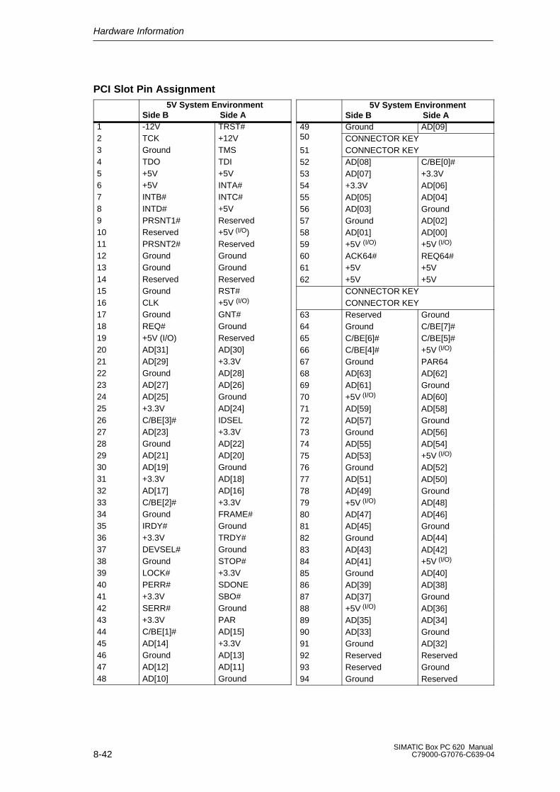
Hardware Information
8-42SIMATIC Box PC 620 Manual
C79000-G7076-C639-04
PCI Slot Pin Assignment5V System Environment
Side B Side A1 -12V TRST#2 TCK +12V3 Ground TMS4 TDO TDI5 +5V +5V6 +5V INTA#7 INTB# INTC#8 INTD# +5V9 PRSNT1# Reserved10 Reserved +5V (I/O)11 PRSNT2# Reserved12 Ground Ground13 Ground Ground14 Reserved Reserved15 Ground RST#16 CLK +5V (I/O)
17 Ground GNT#18 REQ# Ground19 +5V (I/O) Reserved20 AD[31] AD[30]21 AD[29] +3.3V22 Ground AD[28]23 AD[27] AD[26]24 AD[25] Ground25 +3.3V AD[24]26 C/BE[3]# IDSEL27 AD[23] +3.3V28 Ground AD[22]29 AD[21] AD[20]30 AD[19] Ground31 +3.3V AD[18]32 AD[17] AD[16]33 C/BE[2]# +3.3V34 Ground FRAME#35 IRDY# Ground36 +3.3V TRDY#37 DEVSEL# Ground38 Ground STOP#39 LOCK# +3.3V40 PERR# SDONE41 +3.3V SBO#42 SERR# Ground43 +3.3V PAR44 C/BE[1]# AD[15]45 AD[14] +3.3V46 Ground AD[13]47 AD[12] AD[11]48 AD[10] Ground
5V System EnvironmentSide B Side A
49 Ground AD[09]50 CONNECTOR KEY51 CONNECTOR KEY52 AD[08] C/BE[0]#53 AD[07] +3.3V54 +3.3V AD[06]55 AD[05] AD[04]56 AD[03] Ground57 Ground AD[02]58 AD[01] AD[00]59 +5V (I/O) +5V (I/O)
60 ACK64# REQ64#61 +5V +5V62 +5V +5V
CONNECTOR KEYCONNECTOR KEY
63 Reserved Ground64 Ground C/BE[7]#65 C/BE[6]# C/BE[5]#66 C/BE[4]# +5V (I/O)
67 Ground PAR6468 AD[63] AD[62]69 AD[61] Ground70 +5V (I/O) AD[60]71 AD[59] AD[58]72 AD[57] Ground73 Ground AD[56]74 AD[55] AD[54]75 AD[53] +5V (I/O)
76 Ground AD[52]77 AD[51] AD[50]78 AD[49] Ground79 +5V (I/O) AD[48]80 AD[47] AD[46]81 AD[45] Ground82 Ground AD[44]83 AD[43] AD[42]84 AD[41] +5V (I/O)
85 Ground AD[40]86 AD[39] AD[38]87 AD[37] Ground88 +5V (I/O) AD[36]89 AD[35] AD[34]90 AD[33] Ground91 Ground AD[32]92 Reserved Reserved93 Reserved Ground94 Ground Reserved

Hardware Information
8-43SIMATIC Box PC 620 ManualC79000-G7076-C639-04
Assignment of the Slot Specific PCI Bus Signals
PCI SocketPin No.
PCI Slot 1 shared ISA PCI Slot
B16 clk (slot 1) clk (slot2)
A6 inta# intb#
A7 intc# intd#
B7 intb# intc#
B8 intd# inta#
B18 req# (slot 1) req# (slot 2)
A17 gnt# (slot 1) gnt# (slot 2)
A26 ad29 ad30
Hardware Information
8-44SIMATIC Box PC 620 Manual
C79000-G7076-C639-04
8.9 CD-ROM Drive
Depending on the device equipment, a CD-ROM drive is installed in theSIMATIC Box PC 620. The fitting depth of the PC is increased by 20 mm as aresult. The CD-ROM drive allows you to read CDs.
Opening the Drawer
By briefly pressing the eject button, the drawer springs out slightly. Now pull thedrawer out until it clicks into position.
Inserting / Removing CDs
Now insert the CD in the drawer with the labeling face up, and press it firmly downinto the center of the turntable. To remove the CD, hold it by the edges and pullupwards.
!Caution
To avoid too much pressure on the open drawer, always hold the drawer at thefront with one hand when inserting or removing a CD.
Closing the Drawer
Push in the drawer until it closes completely. Do not press the eject button.
Note
The EJECT function offered by various applications for opening the CD-ROMdrawer does not work with this drive.
After the drawer has been closed, the CD is tested and the access display light onthe drive starts to flash:
– If the display flashes continually, the CD is faulty but can still be read,
– If the display flashes several times and then remains lit, the CD you haveinserted is defective and cannot be read.
– The access indicator light is normally lit when the CD is being read.

Hardware Information
8-45SIMATIC Box PC 620 ManualC79000-G7076-C639-04
CD-ROM Front
Emergencyejection
Access LEDTray Eject button
Figure 8-9 CD-ROM Front
!Caution
Risk of data loss and damage to the drive!
CD-ROM drives are sensitive to vibrations and shock. Any vibrations occuringduring operation can lead to damage to the drive or CD.
Emergency Eject
The procedure described below can used to remove a disc from the CD-ROM driveif the Open/Close button is disabled by software or a power failure occurs. In thiscase the CD tray cannot be opened automatically.
1. Turn off the power to the drive (switch off your device if necessary).
2. Insert a steel rod or an opened-up paper clip (with a maximum diameter of 1.3 mmand a mimimum of 55mm) into the emergency eject hole at the front of the driveand push lightly. The CD tray is ejected by about 10 mm. Pull it all the way openby hand and carefully lift the CD out.
at least 55 mm (2.1654”) in length
Figure 8-10 Emergency Ejection
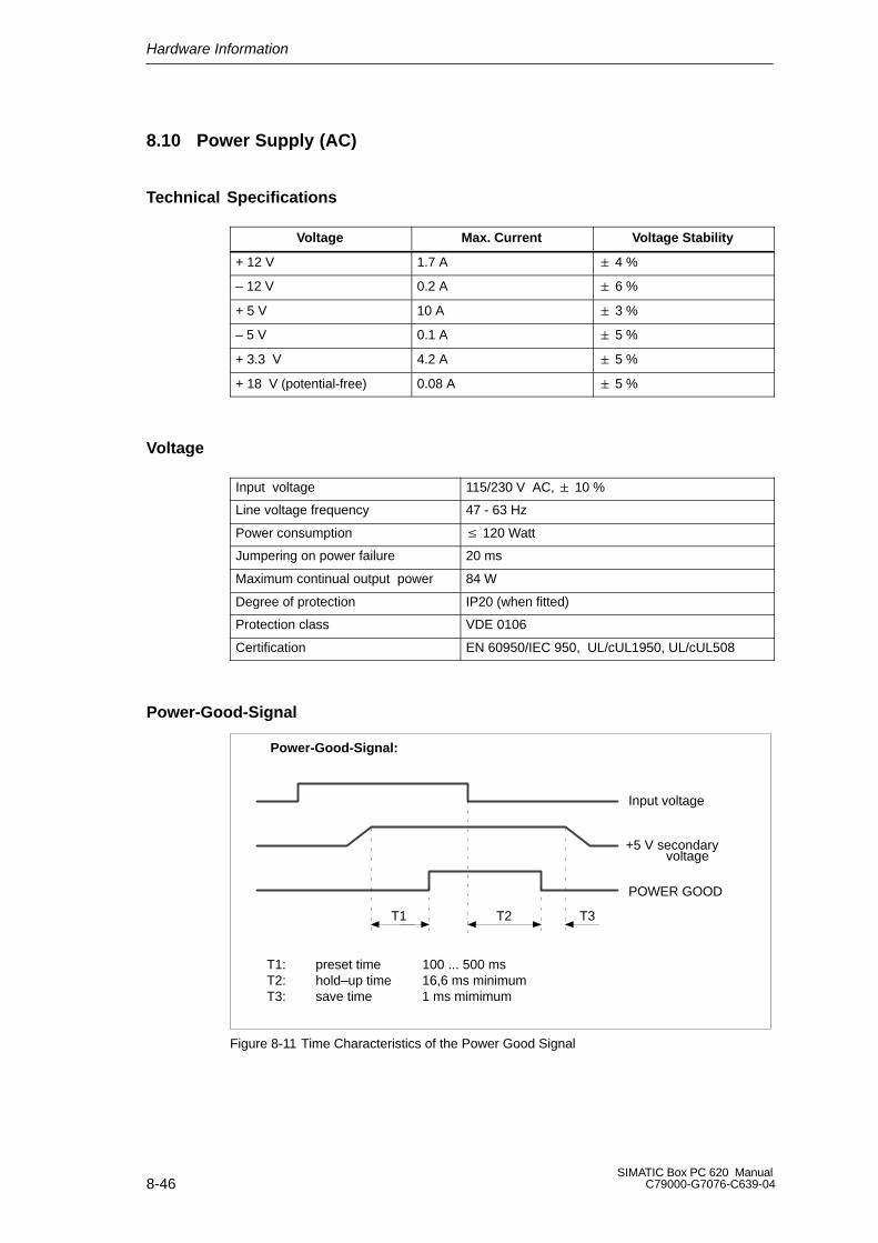
Hardware Information
8-46SIMATIC Box PC 620 Manual
C79000-G7076-C639-04
8.10 Power Supply (AC)
Technical Specifications
Voltage Max. Current Voltage Stability
+ 12 V 1.7 A 4 %
– 12 V 0.2 A 6 %
+ 5 V 10 A 3 %
– 5 V 0.1 A 5 %
+ 3.3 V 4.2 A 5 %
+ 18 V (potential-free) 0.08 A 5 %
Voltage
Input voltage 115/230 V AC, 10 %
Line voltage frequency 47 - 63 Hz
Power consumption 120 Watt
Jumpering on power failure 20 ms
Maximum continual output power 84 W
Degree of protection IP20 (when fitted)
Protection class VDE 0106
Certification EN 60950/IEC 950, UL/cUL1950, UL/cUL508
Power-Good-Signal
T1 T2 T3
Power-Good-Signal:
Input voltage
+5 V secondary
POWER GOOD
T1: preset time 100 ... 500 msT2: hold–up time 16,6 ms minimumT3: save time 1 ms mimimum
voltage
Figure 8-11 Time Characteristics of the Power Good Signal
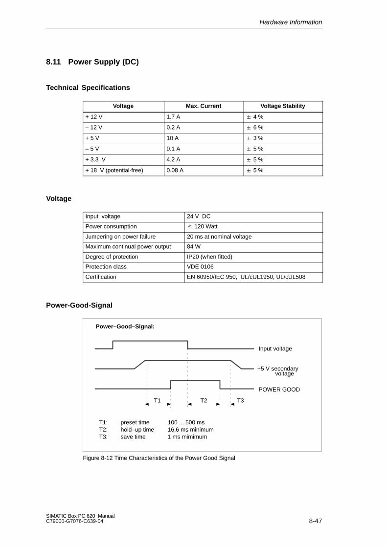
Hardware Information
8-47SIMATIC Box PC 620 ManualC79000-G7076-C639-04
8.11 Power Supply (DC)
Technical Specifications
Voltage Max. Current Voltage Stability
+ 12 V 1.7 A 4 %
– 12 V 0.2 A 6 %
+ 5 V 10 A 3 %
– 5 V 0.1 A 5 %
+ 3.3 V 4.2 A 5 %
+ 18 V (potential-free) 0.08 A 5 %
Voltage
Input voltage 24 V DC
Power consumption 120 Watt
Jumpering on power failure 20 ms at nominal voltage
Maximum continual power output 84 W
Degree of protection IP20 (when fitted)
Protection class VDE 0106
Certification EN 60950/IEC 950, UL/cUL1950, UL/cUL508
Power-Good-Signal
T1 T2 T3
Power–Good–Signal:
Input voltage
+5 V secondary
POWER GOOD
T1: preset time 100 ... 500 msT2: hold–up time 16,6 ms minimumT3: save time 1 ms mimimum
voltage
Figure 8-12 Time Characteristics of the Power Good Signal
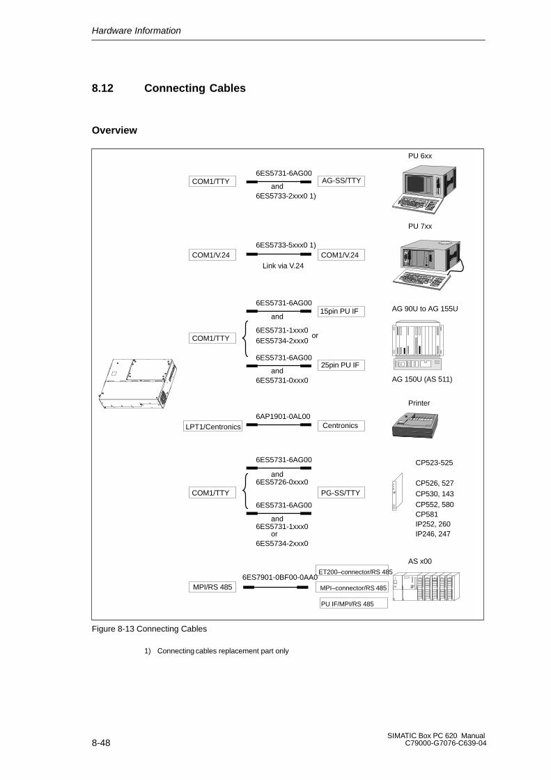
Hardware Information
8-48SIMATIC Box PC 620 Manual
C79000-G7076-C639-04
8.12 Connecting Cables
Overview
PU 6xx
PU 7xx
AG 90U to AG 155U
AG 150U (AS 511)
Printer
CP523-525
CP526, 527CP530, 143CP552, 580CP581IP252, 260IP246, 247
AS x00
COM1/TTY
COM1/TTY
COM1/TTY
COM1/V.24
LPT1/Centronics
COM1/V.24
AG-SS/TTY
PG-SS/TTY
15pin PU IF
25pin PU IF
Centronics
MPI/RS 485 MPI–connector/RS 485
PU IF/MPI/RS 485
ET200–connector/RS 485
6ES5731-6AG00
6ES5733-2xxx0 1)
6ES5733-5xxx0 1)
Link via V.24
6ES5731-6AG00
6ES5731-1xxx0
6ES5731-6AG00
6ES5731-0xxx0
6AP1901-0AL00
6ES5731-6AG00
6ES5726-0xxx0
6ES5731-6AG00
6ES5731-1xxx0
6ES5734-2xxx0
6ES7901-0BF00-0AA0
and
and
and
and
and
or
6ES5734-2xxx0or
Figure 8-13 Connecting Cables
1) Connecting cables replacement part only
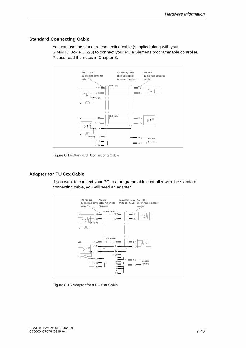
Hardware Information
8-49SIMATIC Box PC 620 ManualC79000-G7076-C639-04
Standard Connecting Cable
You can use the standard connecting cable (supplied along with yourSIMATIC Box PC 620) to connect your PC a Siemens programmable controller.Please read the notes in Chapter 3.
PU 7xx side
25 pin male connector
aktiv
Connecting cable
6ES5 734-2BD20
(in scope of delivery)
AG side
15 pin male connector
passiv
19
18
21
19
9
2
6
330 ohms
330 ohms
9
10
7
8
1
1
3
20
HousingScreen/
housing
+U
–U
+U
–U
Figure 8-14 Standard Connecting Cable
Adapter for PU 6xx Cable
If you want to connect your PC to a programmable controller with the standardconnecting cable, you will need an adapter.
PU 7xx side
25 pin male connector
active
Adapter
6ES5 731-6AG00
(Output 2)
Connecting cable
6ES5 731-1xxx0
AG side
15 pin male connector
passive
330 ohms
330 ohms
19
18
21
22
10
9
2
19 8 6
7219
10 24
251223206234
17
8
1
1
3
20
HousingScreen/housing
+U
–U
+U
–U
Figure 8-15 Adapter for a PU 6xx Cable

Hardware Information
8-50SIMATIC Box PC 620 Manual
C79000-G7076-C639-04
Connecting Cable with 25 Pin Socket Connector
PG 7xx PG 695 II25 pin male connector
active
Adapter6ES5 731-6AG00(Output 2)
Steckleitung6ES5 731-0xxx0
AG-S5, V.2425 pin socketpassive
330 ohms
330 ohms
19
18
21
22
10
9
819
21
19
1821
20
10
20
20
1
3
24
251223
6234
17
1
24
25
Screen
Housing
+U
+U
–U
–U
Figure 8-16 Connecting Cable with 25 Pin Socket Connector
Connecting Cables for the Connection of a PC/PU Link-Up
You can connect your PC to other programming devices via the TTY/COM 1interface with this cable. This cable does not have an order number. Please readthe notes in Chapter 4.
PG 7xxPG 695 II (PC 16-20)25 pin Cannon male connector
active
25 pin Cannon male connector
PG 7xxPG 695 II (PC 16-20)
passive
330 ohms19
18
21
9
10
330 ohms19 18
219
10
1
3
20 20
3
Screen/housing
COM1/TTY port COM1/TTY port
+U
–U
+U
–U
Figure 8-17 Connecting Cables for the Connection of a PC/PU Link-Up
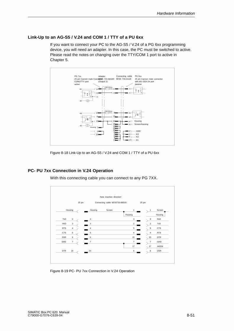
Hardware Information
8-51SIMATIC Box PC 620 ManualC79000-G7076-C639-04
Link-Up to an AG-S5 / V.24 and COM 1 / TTY of a PU 6xx
If you want to connect your PC to the AG-S5 / V.24 of a PG 6xx programmingdevice, you will need an adapter. In this case, the PC must be switched to active.Please read the notes on changing over the TTY/COM 1 port to active inChapter 5.
PG 7xx25 pin Cannon male Coonector 25 pin Cannon male connectorCOM1/TTY portactive
Adapter6ES5 731-6AG00(Output 2)
Connecting cable6ES5 733-2xxx0
PG 6xx
with AG–S5/V.24 portpassive
330 Ohms
330 Ohms
19
18
21
22
10
6
8
19
9
8
21
10
12
10 24
25122320623417
24
25
2
34
17
1
3
20
Housing
Housing
Screen/housing
GND
K3K2
K1
+U
–U
+U
–U
Figure 8-18 Link-Up to an AG-S5 / V.24 and COM 1 / TTY of a PU 6xx
PC- PU 7xx Connection in V.24 Operation
With this connecting cable you can connect to any PG 7XX.
Housing Screen
Housing Housing
ScreenHousing 1
3
2
5
4
20
7
17
6
RxD
TxD
CTS
RTS
DTR
GHD
AKENI
DSR
2
3
4
5
6
7
20
TxD
RxD
RTS
CTS
DSR
GHD
DTR
2
3
4
5
6
7
20
1
3
2
5
4
20
7
17
6
25 pin 25 pinConnecting cable 6ES5733-0BD20
Note insertion direction!
Figure 8-19 PC- PU 7xx Connection in V.24 Operation

Hardware Information
8-52SIMATIC Box PC 620 Manual
C79000-G7076-C639-04

A-1SIMATIC Box PC 620 ManualC79000-G7076-C639-04
Guidelines for handling electrostaticsensitive devices (ESD)
Overview of chapter
In chapter you will find on page
A.1 What does ESD mean? A-2
A.2 Electrostatic charging A-3
A.3 Basic protective measures against discharge of static electricity A-4
A

Guidelines for handling electrostatic
A-2SIMATIC Box PC 620 Manual
C79000-G7076-C639-04
A.1 What does ESD mean?
Definition
All electronic components are equipped with high–integrated modules orcomponents. Conditioned by their technology, these electronic components areextremely sensitive to overvoltages and therefore to discharges of staticelectricity.
The short term ESD has been adopted for these Electrostatic Sensitive Devices/assemblies.
Electrostatic sensitive assemblies are identified by the following symbol:
!Caution
Electrostatic sensitive devices can be destroyed by voltages which are far belowthe limit of perception of human beings. These voltages occur when you touch acomponent or the electrical connections of a assembly without beingelectrostatically discharged. The damage which arises in a assembly as a result ofovervoltage cannot usually be detected immediately, but only becomes apparentafter a lengthy operating period.
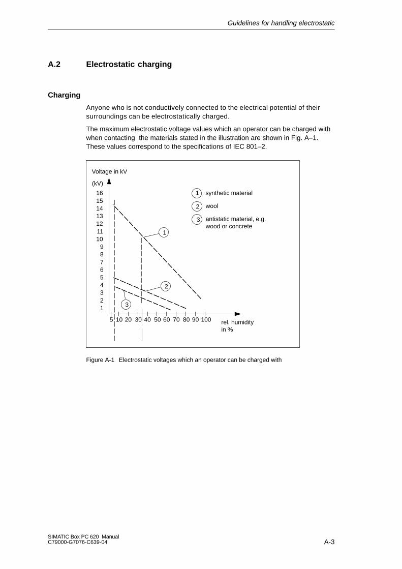
Guidelines for handling electrostatic
A-3SIMATIC Box PC 620 ManualC79000-G7076-C639-04
A.2 Electrostatic charging
Charging
Anyone who is not conductively connected to the electrical potential of theirsurroundings can be electrostatically charged.
The maximum electrostatic voltage values which an operator can be charged withwhen contacting the materials stated in the illustration are shown in Fig. A–1.These values correspond to the specifications of IEC 801–2.
Voltage in kV
123456789
10111213141516
(kV)
5 10 20 30 40 50 60 70 80 90 100 rel. humidityin %
1
3
1 synthetic material
2 wool
3 antistatic material, e.g.wood or concrete
2
Figure A-1 Electrostatic voltages which an operator can be charged with
Guidelines for handling electrostatic
A-4SIMATIC Box PC 620 Manual
C79000-G7076-C639-04
A.3 Basic protective measures against discharge of staticelectricity
Ensuring a good ground connection
When handling electrostatic sensitive devices, ensure that your person, theworkplace and packaging are grounded. In this manner you avoid static charge.
Avoid direct contact
As a general principle, only touch electrostatic sensitive devices when this isunavoidable (e.g. during maintenance work). To prevent discharge energy fromreaching and damaging sensitive components, hold the components in such away that you do not touch the pins or the printed conductors.
If you have to perform measurements on an assembly, discharge your body bytouching a grounded metallic object before carrying out the work. Use onlygrounded measuring instruments.

Glossary-1SIMATIC Box PC 620 ManualC79000-G7076-C639-04
Glossary
What does this Chapter Contain?
This chapter contains a glossary in which you will find a list of the terminology usedin conjunction with the Siemens range of PCs and programming devices and abrief explanation of each of the terms.

Glossary
Glossary-2SIMATIC Box PC 620 Manual
C79000-G7076-C639-04
A
Access Protection
Access to the programs and data of a programming device can be protected bypasswords.
Application
An application is a program which builds directly on, for example, the operatingsystem. Applications on your programming device are MS-DOS/Windows, theSTEP 5 Standard package, GRAPH 5 etc.
ASCII Editor
With an ASCII editor you can edit text files that are stored in ASCII code (AmericanStandard Code of Information Interchange).
B
Base Memory
The base memory is a part of the main memory. It is 640 Kbytes for all program-ming devices. The size is entered in the SETUP menu under the entry “BaseMemory” and is not changed even if the memory is extended.
Bps
The speed (in bits per second) with which information is transmitted over a datalink.
BIOS
BASIC Input Output System
Boot Diskette
A diskette which includes a boot sector, enabling it to load the operating systemfrom the diskette.
Booting
A loading operation which transfers the operating system to the main memory.
Glossary
Glossary-3SIMATIC Box PC 620 ManualC79000-G7076-C639-04
C
Cache
Fast intermediate memory between the work memory and the CPU.
CD ROM
(Compact Disc – Read Only Memory) Removable memory for large amounts ofdata.
Click
Pressing and immediately releasing the left mouse button; this selects objects ortrigger commands.
COM1 Port
The COM1 port is a serial V.24/modem interface. This interface is suitable forasynchronous data transmission. It can also be used to connect printers with aserial interface.
COM2 Port
The COM2 port is a serial V.24 interface which can be used to connect a mouse orother external devices (for example, printers).
Configuration Files
These are files which define the configuration after booting. Examples of such filesare CONFIG.SYS and AUTOEXEC.BAT and registry files.
Configuration Software
The configuration software brings the device configuration up to date whenmodules are installed. This is done either by copying the configuration files sup-plied with the module or by manual configuration.
Cursor
Pointer that shows the position on the screen at which the next entry will appear.
Cursor Control
Keypad on the keyboard for controlling the cursor.
Glossary
Glossary-4SIMATIC Box PC 620 Manual
C79000-G7076-C639-04
D
Device Configuration
The configuration of a programming device contains information on the hardwareand options of the device, such as memory configuration, drive types, monitor,network address etc. The data are stored in a configuration file and enable theoperating system to load the correct device drivers and assign the correct deviceparameters.
If changes are made to the hardware configuration, the user can change entries inthe configuration file using the SETUP program.
DIMM
dual inline memory module. A type of memory board composed of RAM chipsmounted on a circuit board, similar to the more commonly used SIMM (SingleInline Memory Module). DIMMs are characterized by a 64–bit data path and pins(connectors) on each side that are on different circuits and that respond to differentsignals. SIMMs, in contrast, have a 32-bit data path, and their connectors are onthe same circuit and respond to the same signal. While SIMMs must be added inpairs, DIMMs can be added to a computer one at a time.
Diskette
The diskette (floppy disk) is an external direct access memory on which all types offiles and programs can be stored. The storage medium is a round magnetic disk ina plastic cover to protect it from getting scratched.
Disk Drive
The disk drive (floppy disk drive) is used to store programs and data on diskette(write access) or to load from diskette to the computer (read access).
Display
The monitor of the PG 740 PII.
Double-Click
Pressing and releasing the left mouse button very quickly twice in successionwithout moving the mouse. This action is normally to open an object or program.
Drives
Drives are used to hold rotating storage media (diskettes, hard disk, CDs).
Glossary
Glossary-5SIMATIC Box PC 620 ManualC79000-G7076-C639-04
Drivers
These are programs which are part of the operating system. They adapt the datafrom user programs to the specific formats required by the I/O devices such ashard disk, printers and monitors.
Drop-Down Menu
In graphics-supported programs, a menu line is positioned on the top edge of thescreen. The menu titles contained in this line can be set either as drop-down orpull-down menus. Drop-down menus “roll” down as soon as the mouse pointerpasses over a menu title. Pull-down menus only “roll” down when the menu title isclicked on. Different functions can then be called from these menus by moving themouse and clicking on an item in a menu.
E
EPROM/EEPROM Submodules
These are plug-in submodules with EPROM/EEPROM chips. S5 user programscan be stored on them. These programmed submodules are then plugged inspecially designed receptacles in the programmable controller.
Extended Memory
A memory extension can be installed in a programming device to increase the sizeof the memory.
Ethernet
Local network (bus structure) for text and data communication with a datatransmission rate of 10 Mbps.
F
File
A file is a collection of data under one name.
Formatting
Formatting divides the memory area on a magnetic data medium into tracks andsectors. Formatting deletes all the data on a data medium. Every data mediummust be formatted before it is used for the first time.
Glossary
Glossary-6SIMATIC Box PC 620 Manual
C79000-G7076-C639-04
Function Keys
Function keys can be divided into two different types; the normal function keyswhich are assigned a particular function of the computer (for example, delete key),and programmable function keys (softkeys).
G
Gender ChangerUsing the gender changer (25 pin / 25 pin), the COM1/V24/AG SIMATIC PC familyport can be converted to the usual 25-pin male connector.
H
Hard Copy
The output of the complete contents of the screen on a printer is called a hardcopy.
Hard Disk Drive
Hard disk drives (Winchester drives) are a form of magnetic disk memory wherethe magnetic disks are permanently built into the drive.
HMI
Human Machine Interface
I
Interface
An interface is the connection between individual hardware elements such asPLCs, programming devices, printers or monitors via physical connections(cables).
An interface is also the connection between different programs, to enable themto work together.
Interface Module
Module used to connect the hardware I/O.

Glossary
Glossary-7SIMATIC Box PC 620 ManualC79000-G7076-C639-04
Interrupt
The interruption of program processing in the processor of a programmablecontroller by an interrupt event.
IRQ
Interrupt Request
ISA
Industrial Standard Architecture (bus for expansion module)
J
JEIDA
(Japanese Electronics Industry Development Association) Association of Japaneseelectronics manufacturers whose aim is to set up standards worldwide for theminiaturization and flexible application of PC expansion cards. Cooperates withPCMCIA.
K
Keyboard
The keyboard is the collection of keys which are used to input data, text,characters, letters, numbers, special characters and control commands in acomputer. The keyboard forms the input interface between the user and thecomputer.
I
LCD
Liquid Crystal Display
LED
Light-emitting diode (for display and indicating purposes).
LPT1 Port
The LPT1 port (Centronics port) is a parallel interface that can be used to connecta printer.

Glossary
Glossary-8SIMATIC Box PC 620 Manual
C79000-G7076-C639-04
LS 120 drive
The LS 120 drive is compatible with previous 3.5”-disk drives. With the LS 120drive, normal floppy disks (1.44Mbyte) as well as Superdisks with up to 120 Mbytecapacity can be used.
M
Main Memory
The main memory is the complete RAM memory of a programming device.
Memory Card
Memory cards are memory for user programs and parameters in credit-card for-mat, for example, for programmable modules and CPs.
Modem
Communications device that enables a computer to send and receive data over atelephone line. Modulator and demodulator of a signal transmission facility. Itconverts the digital pulses from a computer into analog signals (and vice versa).
Module
Modules are boards (printed-circuit boards) which can be plugged into aprogrammable controller or programming device. They are available, for instance,as central controller modules, interface modules, or as mass memory modules.
Monitor
The monitor or screen is a visual display unit via which the programming devicecommunicates with the user.
Motherboard
The motherboard is the core of the programming device. From here data areprocessed and stored, interfaces and device I/Os are controlled and managed.
Mouse
The mouse is an input device, with which the user inputs coordinates (x,y). Bymoving the mouse, the mouse pointer can be moved at will around the screen. Bypressing the left mouse button, the position is marked. The other mouse keys mayhave different assignments according to the application. With the mouse, objectscan be selected, menus processed and functions started.

Glossary
Glossary-9SIMATIC Box PC 620 ManualC79000-G7076-C639-04
Mouse Pointer
The mouse pointer is moved across the worktop (screen) by means of the mouse.The mouse pointer selects, for example, objects which are to be processed.
MPI/DP
The multipoint interface (MPI) is the programming device interface of SIMATIC S7.It enables access to programmable modules, text displays, and operator panelsfrom a central point. The stations on the MPI can communicate with each other.
MS-DOS
(Microsoft Disk Operating System) is one of the standard operating systems forpersonal computers. It is a single-user system.
Multipoint Interface
The multipoint interface (MPI) is the programming device interface of SIMATICS7/M7. It enables access to programmable modules, text displays, and operatorpanels from a central point. The stations on the MPI can communicate with eachother.
N
Network
Link between programming devices and programmable controllers by means ofinterface modules, physical cables, and the corresponding software to allow dataexchange between the devices.
O
OP
Operator Panels serve as a quick way to control machines. Expected values canbe set, machine data called up, or plants created.
Operating System
Collective term for all programs which, in conjunction with the hardware, controland monitor execution of the user programs, the distribution of resources amongthe individual user programs, and the maintenance of the operating mode (forexample, Windows 98).
Glossary
Glossary-10SIMATIC Box PC 620 Manual
C79000-G7076-C639-04
P
Parallel Interface
Information is transmitted a byte at a time via a parallel interface (port). Thismeans that the transmission rate is very fast. The programming devices have aparallel interface (LPT) to connect a printer.
Password
See Access Protection
PC
Personal computer
PC Card
A PC Card is a removable device, approximately the same size as a credit card,that is designed to plug into a PCMCIA slot. Release 1 of the PCMCIA specifica-tion specified a Type I card that is 3.3 millimeters thick and is intended to be usedprimarily as a memory-related peripheral. Release 2 of the PCMCIA specificationspecifies both a 5-millimeter-thick Type II card and a 10.5-millimeter-thick Type IIIcard. Type II cards accommodate devices such as modem, fax, and networkcards. Type III cards accommodate devices that require more space, such as wire-less communications devices and rotating storage media (such as hard disks).
PCI
Peripheral Component Interconnect (fast expansion bus).
PCMCIA
(Personal Computer Memory Card International Association). Association of about450 computer companies with the aim of setting worldwide standards forminiaturizing PC expansion cards and making their use more flexible, offering themarket a basis for development. Cooperates with JEIDA.
PG
Programming device
PG Interface
The PG (programming device) interface is a serial port; it is located on a CPU, aCP/IP, or a coordinator module (PG-MUX) and is used to connect a programmingdevice. Some CPUs may have two PG interfaces as an option.

Glossary
Glossary-11SIMATIC Box PC 620 ManualC79000-G7076-C639-04
PIC
SIMATIC programmable controller
Plug and play
Generally, a reference to the ability of a computer system to automatically confi-gure a device added to it. When capitalized and, especially, when abbreviated PnP,a set of specifications developed by Intel and Microsoft that allows a PC to confi-gure itself automatically to work with peripherals such as monitors, modems, andprinters. A user can plug in a peripheral and ”play” it without manually configuringthe system. A Plug and Play PC requires both a BIOS that supports Plug and Playand a Plug and Play expansion card.
Programmable Controller
The programmable logical controllers (PLC) of the SIMATIC systems (S5 or S7)consist of a central controller, one or more CPUs, and various I/O modules.
Pull-Down Menu
See Drop-Down Menu
R
RAM
RAM (Random Access Memory) is a read/write memory in which every memorylocation can be addressed individually and its contents changed. RAM is used tostore data and programs.
ROM
ROM (Read Only Memory) is a memory in which every memory location can beaddressed individually. The stored programs and data are permanentlyprogrammed at the factory before delivery and are not lost in the event of a powerfailure.
RTC
Real-time clock
Glossary
Glossary-12SIMATIC Box PC 620 Manual
C79000-G7076-C639-04
S
SCSI Interface
Small Computer System Interface. Interface for connecting SCSI devices (harddisk drives, CD-ROM drives).
Serial Interface
Data are transmitted one bit at a time via a serial interface (port); they are usedwhere large distances have to be covered using the minimum amount of cabling.
SETUP (BIOS Setup)
A program in which information about the device configuration (that is, theconfiguration of the programming device’s hardware) is defined. The deviceconfiguration of the programming device is preset with defaults. Changes must the-refore be entered in the SETUP if a memory extension, new modules, or a newdrive are added to the hardware configuration.
SIMATIC S5 Memory Submodule
Memory submodules for SIMATIC S5 that can be written with the programmer andinserted in an S5 programmable controller.
SIMATIC Memory Cards
Memory submodules in credit-card format for SIMATIC S5 and SIMATIC S7 whichare programmed with the PG 740 PII and can be plugged in an S5 or S7programmable controller.
SINEC L2 (PROFIBUS)
Bus system on the basis of the PROFIBUS standard. Components of the SIMATICS5 and S7 series (for example, programming device, programmable controller,remote I/O) can be networked directly using SINEC L2.
SINEC H1(ETHERNET)
Bus system on the basis of the ETHERNET standard. Components of theSIMATIC S5 and S7 series (for example, programming device, programmablecontroller, remote I/O) can be networked directly using SINEC H1 interfacemodules.
Software
The collective term for all programs which are used on a computer. The operatingsystem and the user programs are part of the concept “software”.
Glossary
Glossary-13SIMATIC Box PC 620 ManualC79000-G7076-C639-04
SOM
Safecard On Motherboard consists of monitoring blocks on the motherboard, adriver and the SOM program. This allows the monitoring functions of differenttemperatures and the way programs run (Watchdog).
STEP 5 Basic Package
This is a software package which represents the basis for all other STEP 5software packages. With the programmer (PG), this package is used to programPLCs in the SIMATIC S5 family. The language used is known as STEP 5.
STEP 7
Programming software for the creation of user programs for SIMATIC S7 control.
T
Text Cursor
The cursor shows where text may be entered, for example, in text editors and indialog windows. In many applications the position of the cursor can be changed bymoving and clicking the mouse pointer.
TFT Display
Thin-film-transistor color display
Trackball
The trackball is used as an input device for programs serviced by a mouse. On thePG 740 PIII, the trackball is integrated in the keyboard.
U
USB
Universal Serial Bus. A serial bus with a data transfer rate of 12 megabits persecond (Mbps) for connecting peripherals to a microcomputer. USB can connectup to 127 peripherals, such as external CD-ROM drives, printers, modems, mice,and keyboards, to the system through a single, general-purpose port. This isaccomplished by daisy chaining peripherals together. USB is designed to supportthe ability to automatically add and configure new devices and the ability to addsuch devices without having to shut down and restart the system (hot plugging).
Glossary
Glossary-14SIMATIC Box PC 620 Manual
C79000-G7076-C639-04
User Interface
The software-controlled menus and screens on the monitor through which the usercommunicates with the program.
User Program
A collection of all the instructions, declarations, and data for signal processing, bywhich a system (or process) is controlled or influenced. It is linked to aprogrammable module (for example, CPU, FM) and can be structured in smallerunits (blocks).
V
V.24 Interface
The V.24 interface is a standardized interface for data transmission. Printers,modems, and other hardware modules can be connected to a V.24 interface.
VGA
(Video Graphics Array)Color graphics control mode
W
Warm Restart
A warm restart is a restart after a program has been aborted. The operatingsystem is reloaded and restarted. A warm restart is performed with the keycombination CTRL+ALT+DEL.
Work Memory
The work memory is a RAM memory in the CPU which the processor accessesduring user program processing.
Write Protection
Write protection for files or diskettes
Write protection for files; this type of write protection is stored in the computerand is allocated by the system manager.
Diskette write protection; for 5 1/4 in. diskettes by blanking out the hole on theright-hand edge with an adhesive label, for 3 1/2 in. diskettes or EOD disks byopening the write protection hole.

Index-1SIMATIC Box PC 620 ManualC79000-G7076-C639-04
Index
AAddress areas, 8-4Assignment, Internal Ports, 8-30AT Cards, 5-13
BBackup Battery, 3-14, 5-11Battery, Safety notes, 3-14BIOS, 6-2
date, 6-6time, 6-6
Bus board, 8-38removal and installation, 5-24
CCard, note, 5-13Cardbus, 4-10CD ROM Drive, 3-11, 8-44CD-ROM drive, removal and installation,
5-20Clock, 3-14, 5-11COM 1, 8-15COM 2, 8-17Components, Current Requirement, 8-2Connecting, 4-13
a Mouse, 4-7a PS/2 Keyboard, 4-8the Monitor, 4-6the PC, 2-10the Printer, 4-5, 4-6USB Periphery, 4-9
Connecting Cables, 8-48Connection
under Windows, 4-21via MPI/DP Interface, 4-18via PROFIBUS, 4-20
Current Requirement, components, 8-2
DDefault Setup Settings, 6-30Device Configuration, 6-1, 6-2
Device for holding down the modules, remo-val and installation, 5-15
Diagnosing, Errors, 7-2Diskettes, 3-9Display Port, 8-27Display Select Inputs, 8-28DMA Assignments, 8-7Drive LS 120, Glossary-8Drives, 3-9
EError Diagnosis, 7-1ESD guidelines, 5-2Ethernet RJ45 Connection, 8-23Expansion card, removal and installation,
5-17Expansion Cards, maximum dimensions,
5-13Expansions, 5-1external keyboard, 8-20
FFan, removal and installation, 5-26Floppy disk drive, removal and installation,
5-21Floppy Disk Drive Type, setting, 6-6Front Ports, 3-5Function, Safecard, 8-11Functions, 1-2
GGender Changer, 8-16
HHard Disk Drive, 3-11Hard disk drive, removal and installation,
5-18Hard Disk Drive Type, setting, 6-6Hardware Information, 8-1
Index
Index-2SIMATIC Box PC 620 Manual
C79000-G7076-C639-04
II/O address area, 8-4Inbetriebnehmen, Warnung, 2-3Industrial Ethernet, 4-21Installing, 2-3Interface, USB, Glossary-13Interrupt Assignments, 8-8Interrupt Controller, 8-9
JJumper settings, 4-17
LLithium battery, 3-14, 5-11LPT 1, 8-18LS 120 Drive, 3-10, Glossary-8LS 120 drive, removal and installation, 5-22
MMemory address area, 8-4Memory Addresses, 8-5Memory submodules, 5-9Monitoring functions, 8-11Monitors, 4-6Motherboard, 5-7
removal and installation, 5-25MPI/DP Socket Connector, 8-22MPI/PROFIBUS Network, 4-19
NNote
card, 5-13PCI Cards, long, 5-14
OOpening the PC, 5-4
PParallel Port, 8-18PC Card, 6-33PC Card Port, 3-7, 4-10PCI Cards, long, 5-14
note, 5-14
PCI cards, short , 5-14Peripheral units, shielding, approval for ope-
ration, 3-2Permissible fitting postions, 2-8Point to point connection, 4-13Ports, 1-3, 3-2, 3-3, 3-5, 8-14POST Codes, 7-4Power connection, Safety notes, 4-3Power On Self Test, 7-3Power supply, 4-2Power Supply (AC), technical data, 8-46Power Supply (DC), technical data, 8-47Power supply unit, 2-9
removal and installation, 5-23Power systems, 4-2Processor Upgrade, 5-27Product overview, 1-1PROFIBUS, 4-20PS/2 Mouse Port, 8-19
RRange of Application, 1-2Removal and installation
bus board, 5-24CD-ROM drive, 5-20Device for holding down the modules,
5-15Expansion card, 5-17fan, 5-26floppy disk drive, 5-21LS 120 drive, 5-22motherboard, 5-25power supply unit, 5-23
Reset Button, 5-29
SSafety notes
Battery, 3-14Power connection, 4-3
Serial Port, 8-15, 8-17Setting, Hard Disk Drive Type, 6-6Setting up, 4-1Setup, 6-2
Floppy Disk Drive Type, 6-6Memory Cache, 6-9
SETUP Menus, 6-2Standard Connecting Cable, 8-49Starting SETUP, 6-2Switching off the PC, 2-10

Index
Index-3SIMATIC Box PC 620 ManualC79000-G7076-C639-04
Switching on the PC, 2-10Switching to Active/Passive, 4-17
TTransport, 2-11TTY Port, 4-14TTY Jumper, 5-28
UUnpacking, 2-2USB interface, Glossary-13USB port, 3-6
VVGA Port, 3-5
VGA Socket Connector, 8-24Video Modes, 8-10
WWarnung, Inbetriebnehmen, 2-3Watchdog
Function, 8-13monitoring times, 8-13reactions, 8-13
XXT Cards, 5-13

Index
Index-4SIMATIC Box PC 620 Manual
C79000-G7076-C639-04