simcenter 3d v12 yenİlİkler sunumu · nastran applicability • sol 401 and sol 402 similarities...
TRANSCRIPT

Unrestricted © Siemens AG 2017
Page 2 Siemens PLM Software
Major themes for release
Simcenter 3D
Generative Design Technology Integration Nonlinear Analysis
Industry Workflows
Unrestricted © Siemens AG 2017
Page 3 Siemens PLM Software
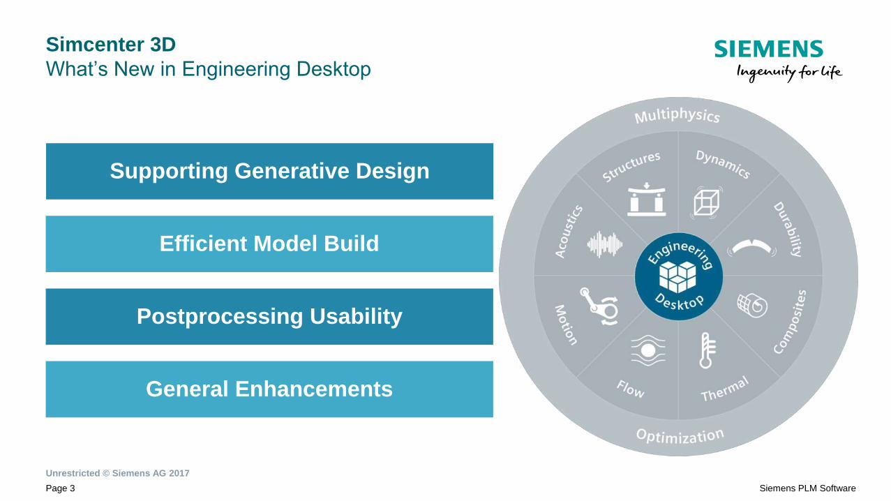
Simcenter 3D
What’s New in Engineering Desktop
Efficient Model Build
Supporting Generative Design
Postprocessing Usability
General Enhancements

HIGHLIGHTS
Topology Optimization in Design
Convergent Modeling
Integration with HEEDS
Supporting Generative Design

Unrestricted © Siemens AG 2017
Page 5 Siemens PLM Software
Topology Optimization in the Design Environment
CHALLENGE:
Enable simulation-led design optimization
SOLUTION:
Topology Optimization in the
Design Environment

Unrestricted © Siemens AG 2017
Page 6 Siemens PLM Software
Topology Optimization in the Design Environment
Powerful optimization tools for
the designer
• Work on a single part or in an assembly
context
• Specify realistic manufacturing constraints
• Output geometry directly to Additive
Manufacturing / 3D printing
• Complete topology optimization process in
a very short time

Unrestricted © Siemens AG 2017
Page 7 Siemens PLM Software
Convergent Modeling
CHALLENGE:
Two-way transfer of geometric data
SOLUTION:
Convergent Modeling in Design
and Simulation

Unrestricted © Siemens AG 2017
Page 8 Siemens PLM Software
Convergent Modeling
Create Convergent Bodies from
polygon geometry
• Easily transfer CAE geometry back to
design
• Enable designer to incorporate changes
resulting from CAE studies
• Leverage Reverse Engineering toolset in
Modeling for Convergent Body operations

Unrestricted © Siemens AG 2017
Page 9 Siemens PLM Software
Convergent Modeling
Bring legacy mesh data to life
• Automatically convert meshes into polygon
faces and bodies
• Rapid creation of new geometry for orphan
meshes
• Make design changes using Modeling tools
and update the mesh

Unrestricted © Siemens AG 2017
Page 10 Siemens PLM Software

HIGHLIGHTS
Selection Recipes
Universal Connections
Efficient Model Build

Unrestricted © Siemens AG 2017
Page 14 Siemens PLM Software
Selection Recipes
CHALLENGE:
Create robust design-simulation updates
SOLUTION:
Automated rule-based
selections for loads and
boundary conditions

Unrestricted © Siemens AG 2017
Page 15 Siemens PLM Software

Unrestricted © Siemens AG 2017
Page 16 Siemens PLM Software
Selection Recipes
Make dramatic design
modifications and still benefit
from automated simulation model
updates
• Create new Selection Recipes using
attributes bounding volumes, label ranges or
coordinates
• Supports a wide range of potential workflows

Unrestricted © Siemens AG 2017
Page 17 Siemens PLM Software

Unrestricted © Siemens AG 2017
Page 18 Siemens PLM Software
Universal Connections
CHALLENGE:
Manage connections in large assemblies
SOLUTION:
Create and validate connections
in a solver-neutral framework
with Universal Connections

Unrestricted © Siemens AG 2017
Page 19 Siemens PLM Software
Efficient Model Build
Universal Connections
AQA
Nastran
Abaqus
…

Unrestricted © Siemens AG 2017
Page 20 Siemens PLM Software

Unrestricted © Siemens AG 2017
Page 21 Siemens PLM Software
Universal Connections
Assembly Quality Audit
• Specify and run multiple checks on the
assembly model
• Identify, zoom to, and fix any problems that
are identified

HIGHLIGHTS
Ribbon Toolbar
Nodal Force Reports
Simcenter Results Viewer
Postprocessing Usability

Unrestricted © Siemens AG 2017
Page 23 Siemens PLM Software
Postprocessing Usability
CHALLENGE:
Improve Postprocessing efficiency
SOLUTION:
Provide easy access to powerful
Postprocessing tools

Unrestricted © Siemens AG 2017
Page 24 Siemens PLM Software
Ribbon Toolbar
Quick Access to Key Tools
• Instant access to display controls
• More options for contour display
• Interactive legend
• Access to Preprocessing display controls
from in the Postprocessor

Unrestricted © Siemens AG 2017
Page 25 Siemens PLM Software
Nodal Force Reports
Enable for more efficient
workflows
• Preprocessing object, similar to Results
Probes
• Much more efficient than existing free body
diagrams
• Output can be used for breakout modeling

Unrestricted © Siemens AG 2017
Page 26 Siemens PLM Software
Postprocessing Usabilty
Simcenter Results Viewer
Share results across the
Enterprise
• Tailored to analysts’ needs, results can be
shared easily without a full Pre/Post license
• Use as a standalone application and import
results
• Automatically open and display results data
stored in Teamcenter

HIGHLIGHTS
Meshing enhancements
Preprocessing enhancements
Postprocessing enhancements
General Enhancements
Unrestricted © Siemens AG 2017
Page 28 Siemens PLM Software
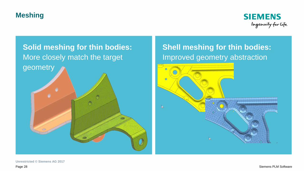
Solid meshing for thin bodies:
More closely match the target
geometry
Meshing
Shell meshing for thin bodies:
Improved geometry abstraction

Unrestricted © Siemens AG 2017
Page 29 Siemens PLM Software
Solid tetrahedral meshing size
controls
Meshing
Automated meshing for cyclic
symmetry

Unrestricted © Siemens AG 2017
Page 30 Siemens PLM Software
Annotations in Preprocessing
Preprocessing
Display controls

Unrestricted © Siemens AG 2017
Page 31 Siemens PLM Software
Label management extended to
more entity types
Preprocessing
Model section views include
element intersections

Unrestricted © Siemens AG 2017
Page 32 Siemens PLM Software
Edit query curves
Postprocessing
XY Graph are fully interactive
and more

Unrestricted © Siemens AG 2017
Page 33 Siemens PLM Software
Simcenter 3D
What’s New in Engineering Desktop
Efficient Model Build
Supporting Generative Design
Postprocessing Usability
General Enhancements

Unrestricted © Siemens AG 2017
Page 34 Siemens PLM Software
Simcenter 3D
What’s New in Motion
External File & Model Setup
Simulation & Modeling Improvements
Postprocessing Usability
Teamcenter Support for Motion

HIGHLIGHTS
Submechanisms
Analytical 3D Contacts
Flexible Links as Spline Beams
Flexible Links with ANSYS
Simulation & Modeling
Improvements

Unrestricted © Siemens AG 2017
Page 36 Siemens PLM Software
Submechanisms
Efficiently assemble and manage
modular mechanisms
• Assemble complex mechanisms from its
constituents subsystems
• Build and test each subsystem before
combining in the multi level parent
• Re-use existing models defined and owned by
multiple specialist teams

Unrestricted © Siemens AG 2017
Page 37 Siemens PLM Software
Analytical Contact
Compute 3D contact faster and with
smoother contact force results
• Does not require solid CAD geometry
• Formulations based on basic shapes
(spheres, extruded and revolved geometries)
• Stiffness and damping from material
properties
1 Solid-Solid
contact
1 Analytical
Sphere-Extrusion
Result & Gain
CPU: 36 sec CPU: 1 sec Fast; no peak due
to facetization of
CAD geometry
Pin contact right
after the slot bend

Unrestricted © Siemens AG 2017
Page 38 Siemens PLM Software
Simcenter Motion Technical Capabilities
Contacts
3D Contact
▪ Model collision between 2 bodies
▪ Liftoff allowed
Geometric Contacts
▪ Constrain geometry to specified criteria
Comparison with previous NX Motion solver:
▪ Improved tessellation control
▪ Performance and Quality Improvements:
▪ Speed up factor of 5 to 8 possible
▪ internal and customer tests
▪ 90% of tests show quality improvements
Unrestricted © Siemens AG 2017
Page 39 Siemens PLM Software
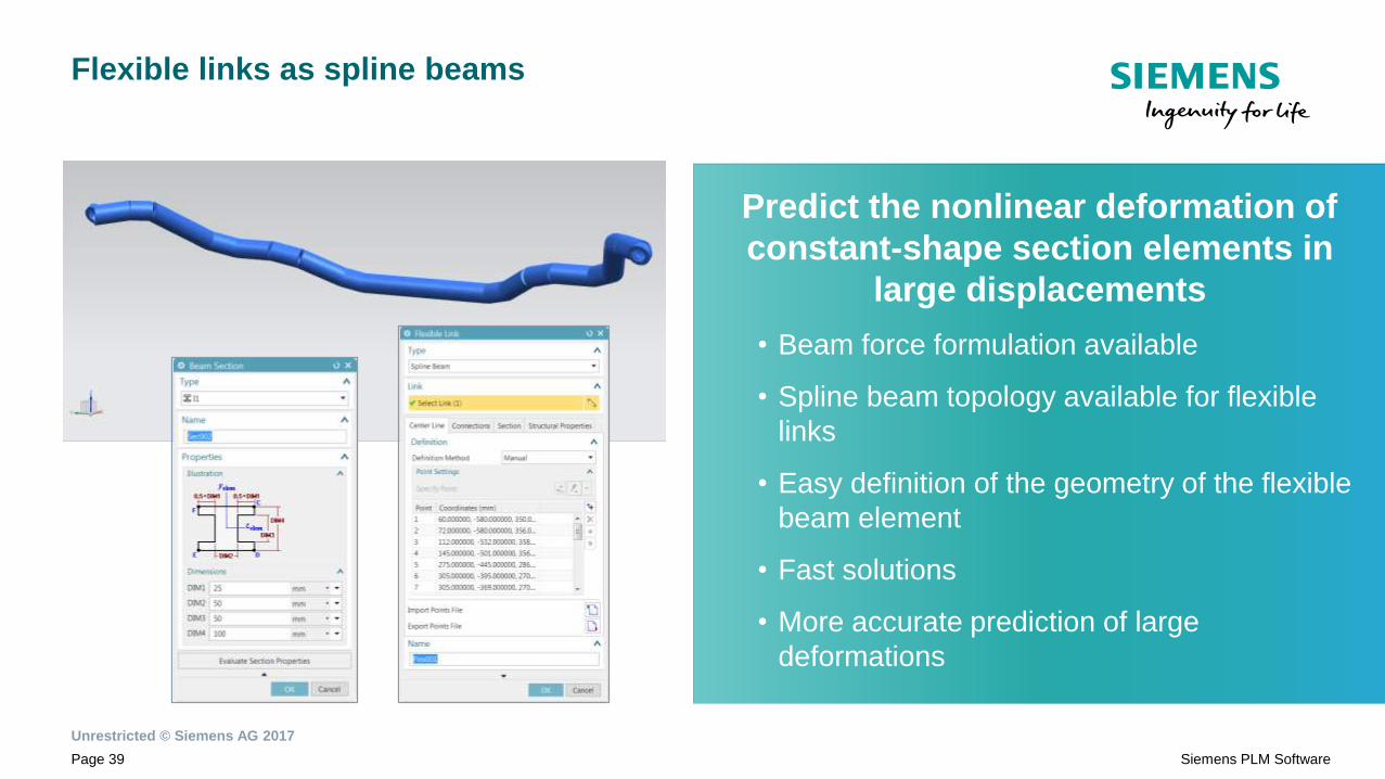
Flexible links as spline beams
Predict the nonlinear deformation of
constant-shape section elements in
large displacements
• Beam force formulation available
• Spline beam topology available for flexible
links
• Easy definition of the geometry of the flexible
beam element
• Fast solutions
• More accurate prediction of large
deformations

Unrestricted © Siemens AG 2017
Page 40 Siemens PLM Software
Spline Beam
Application on a Landing Gear
Workflow
• In a landing gear model, make the piston strut
flexible with spline beam formulation
• Run a drop test analysis
Final goal
• Check how piston strut flexibility affects drop test
results
Piston as Spline beam
Tire/Road reaction
comparing with and
without a flexible piston

Unrestricted © Siemens AG 2017
Page 41 Siemens PLM Software
Workflow
• In a rigid axle suspension model with leaf springs, make
leaf flexible with spline beam formulation
• Run a vertical travel analysis
Final goal
• Measure vertical stiffness of the suspension
• Reuse within different trailer contexts (pulled by vehicle
and load cases)
Spline Beam
Application on a trailer leaf suspension

HIGHLIGHTS
CAD-independent Motion Modeling
Text-based Modeling
Profile elements
Integration with HEEDS
File & Model Setup

Unrestricted © Siemens AG 2017
Page 44 Siemens PLM Software
CAD-independent Motion Modeling
Work with Motion data independent
from design data
• Motion models no longer require a master
part file
• Create simple geometries directly within the
Motion application
• Motion-based geometries can be saved in
the Motion file directly, no associated part
files required
• Associate CAD geometry to the motion
model later

Unrestricted © Siemens AG 2017
Page 45 Siemens PLM Software
Text-based Modeling
Perform motion simulation without the
need for Simcenter 3D Motion interface
• Based on Motion Definition File (MDF) – XML
format
• Extensibility to add motion elements for
vertical applications
• Perform automated computations thanks to
standalone Solver and Result Viewer

Unrestricted © Siemens AG 2017
Page 46 Siemens PLM Software
Text-Based Motion Modeling Workflow
Simcenter Motion
Solver
Motion Definition File
.MDEF (xml)Motion Results
Reader
Users Modeling Solving Post-Processing
Analyst
Methods
expert
Simcenter
Results ViewerVertical applications
Background
(Command)
Analyst
Designer
Simcenter Modeling
DOE and Optimization with HEEDS
Data and Process Management with Teamcenter
Simcenter ModelingForeground
Or
Background

Unrestricted © Siemens AG 2017
Page 47 Siemens PLM Software
Profile elements
Create 2D curves and 3D surfaces from
external files
• Straightforward re-use of existing input data
• Supporting text or MS Excel format for easy
editing of the content and direct input
associativity
• Minimize the number of required external files
through support of multiple data sets in the
same file
Unrestricted © Siemens AG 2017
Page 48 Siemens PLM Software
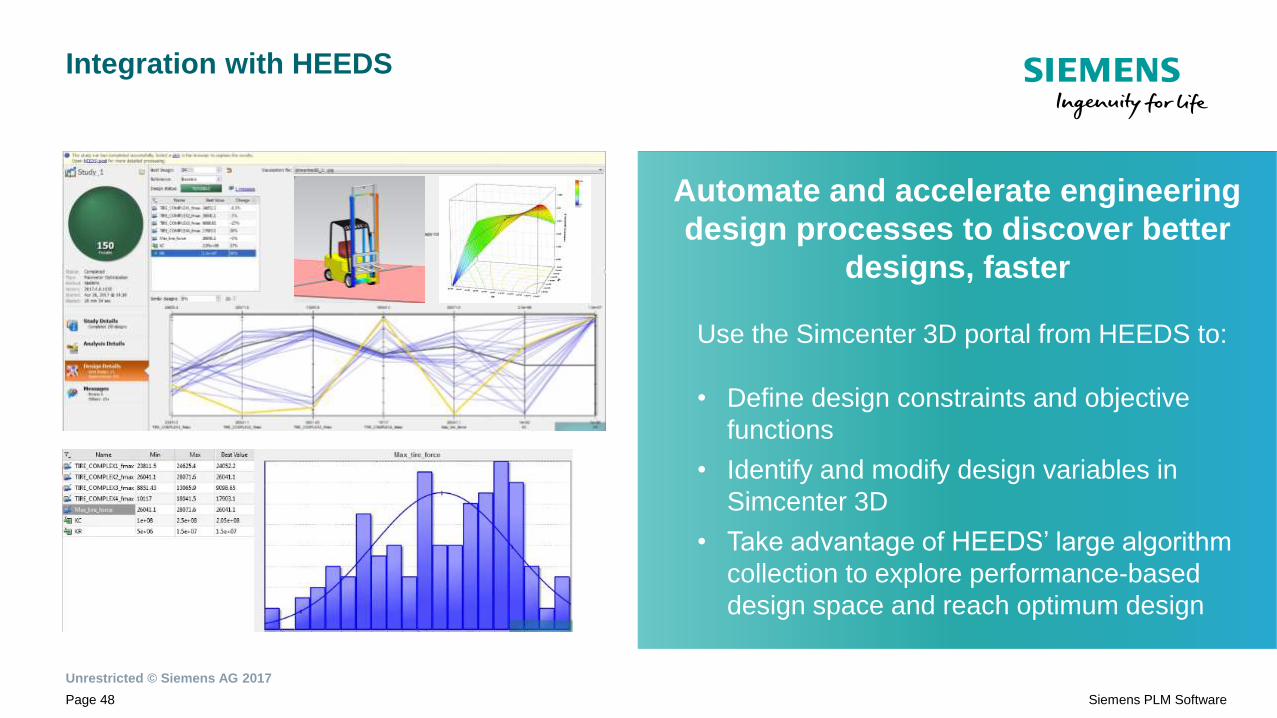
Integration with HEEDS
Automate and accelerate engineering
design processes to discover better
designs, faster
Use the Simcenter 3D portal from HEEDS to:
• Define design constraints and objective
functions
• Identify and modify design variables in
Simcenter 3D
• Take advantage of HEEDS’ large algorithm
collection to explore performance-based
design space and reach optimum design

HIGHLIGHTS
Results Viewer
Post Processing & XY Graph
Usability
Postprocessing Usability

Unrestricted © Siemens AG 2017
Page 50 Siemens PLM Software
Results Viewer
Provide easy access to powerful
postprocessing tools
• Lighter-weight postprocessing tool to quickly
review results
• Use for viewing results without launching full-
blown Simcenter 3D interface
• New scenario-based postprocessing to
visualize and graph data from several types
of data sources in multiple synchronized
viewports
• Automatically open and display results data
stored in Teamcenter

Unrestricted © Siemens AG 2017
Page 51 Siemens PLM Software
Post Processing & XY Graph Usability
Improved the user experience in XY
results output
• Optimize the screen space
• Maintain readability for window shrinking and
extending
• Enhancing results reviewing and reporting
with probing and legend editing
• Ease-of-use and ability to reuse of your
favorite Templates

HIGHLIGHTS
Motion Data Model in Teamcenter
Motion Study Workset
Teamcenter Support for Motion
Unrestricted © Siemens AG 2017
Page 53 Siemens PLM Software
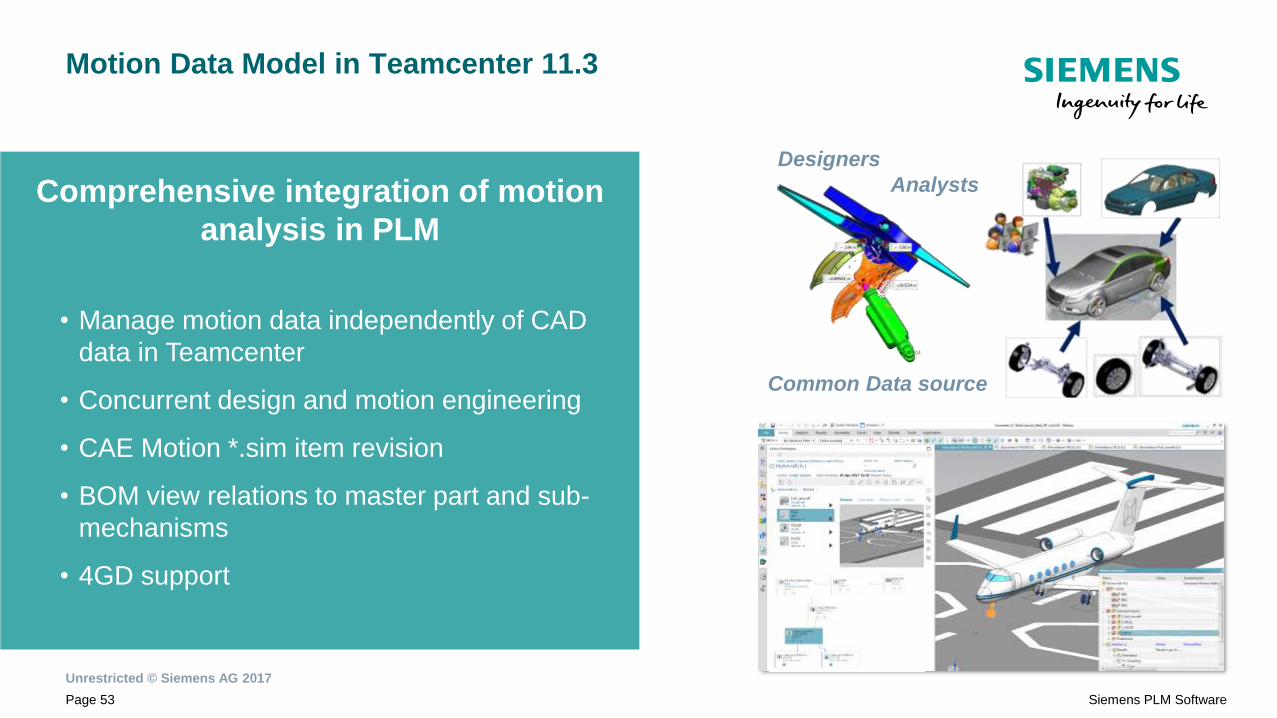
Motion Data Model in Teamcenter 11.3
Designers
Analysts
Common Data source
Comprehensive integration of motion
analysis in PLM
• Manage motion data independently of CAD
data in Teamcenter
• Concurrent design and motion engineering
• CAE Motion *.sim item revision
• BOM view relations to master part and sub-
mechanisms
• 4GD support
Unrestricted © Siemens AG 2017
Page 54 Siemens PLM Software
Summary
External File & Model Setup
Simulation & Modeling Improvements
Postprocessing Usability
Teamcenter Support for Motion

Unrestricted © Siemens AG 2017
Page 55 Siemens PLM Software
Simcenter Structures Solutions
Simcenter 12 Structures
Main areas of focus for Simcenter 12 Structures:
• Multistep Nonlinear
• Topology Optimization
• Composite Curing
• Simcenter Environments
Products encompassed:
• NX Nastran with SOL401/SOL402
• Samcef
• Simcenter Environments for NX Nastran and Samcef
Linear Statics
Modal
Optimization
Nonlinear
Buckling
Composites

Unrestricted © Siemens AG 2017
Page 56 Siemens PLM Software
Simcenter Nonlinear FE solvers
Family tree
Samcef
solver
• Material Library
• Element Formulations
• Matrix Solvers
• Memory Allocation
• Output Formats
• Numerical Strategies
SOL 402
(+ environment)
Products
Solvers
Technologies
SOL 401
(+ environment)
Samcef
(+ environment)+ user interaction
Core solver engines and
associated architectures
• Components and algorithms
• Element and result consistency
• Leverage strength of each engine
NX Nastran
solver
Nastran modeling language (BDF) Nastran modeling language (BDF) Samcef modeling language (DAT)
NXN Multistep Samcef
Unrestricted © Siemens AG 2017
Page 57 Siemens PLM Software
NX Nastran Multistep Nonlinear Implementations
SOL 401 and 402 Core Capability
• Multi-Step solutions
• Large displacement
• Plasticity
• Creep
• Contact
• Material Models
SOL 402 Difference
• Composites
• Nonlinear mechanism
SOL 401 Difference
• Multiphysics couplings
Planned
Commonalties/DifferencesMultistep Solutions:
• SOL 401 and 402 provides general purpose non-linear solution
capability
• SOL 401 Multistep – based on traditional NX Nastran architecture
• SOL 402 Multistep Kinematic – based on integration of Samcef in NX
Nastran
Applicability
• SOL 401 and SOL 402 similarities
• Use many of the same formulations and give nearly same results
• Core set of capabilities that are the same and can be used for same
applications
• Use same Nastran inputs and outputs. Easy to convert one solution to
the other
• SOL 401 and SOL 402 differentiations
• SOL 402 can better support nonlinear kinematic behavior. To be
exposed in later releases
• SOL 401 can be used for multiphysics cosimulation

Unrestricted © Siemens AG 2017
Page 58 Siemens PLM Software
.
Topology Optimization for Analysts
SOL401
Agenda
SOL402
Samcef

Topology
Optimization for
Analysts

Unrestricted © Siemens AG 2017
Page 60 Siemens PLM Software
Topology Optimization for the Analyst – Highlights
• Hosted in Simcenter 3D Engineering Desktop enabling
complete workflow from concept to final design. The
results of a Topology Optimization is not the finish, just the
start of the design work.
• Topology Optimization technology integrated into NX
Nastran using the production proven SOL200 optimization
architecture.
• Multiple Design Areas with different materials.
• Multiple different solution types in the same optimization.
• Multiple variants of the Optimization setup to study the
impact of different options and parameters.
• Solid and Lattice zone prediction – Designing for a Lattice,
not retro-fitting.
CAD Part/Assy
Build the FE Model
Design/Frozen Area(s)
Objective
ConstraintsManufacturing
ConstraintsSolution
ParametersResults Study
Results Selection
Verification of Selected Results
Output of Smoothed Geometry
Further Design Work based on Topology Optimized results
Workflow Solution
BCC FCC EDGE
OCTA OCTET BCCUB
FCCUB BC-FC BFECB

Unrestricted © Siemens AG 2017
Page 61 Siemens PLM Software
Topology Optimization for the Analyst
• Many alternative methods to build the model.
• Mesh only, CAD geometry based.
• All NX Nastran element types to support the
Design Space.
• Multiple solution types in the same optimization
• Linear Statics
• Normal Modes
• Direct Frequency
• Modal Frequency
• Wide range of responses available for an Objective
& Constraints. These responses also have multiple
sub-options.
Total Model Weight
Design Area Weight
Total Model Volume
Compliance
Normal Modes
Bucking Modes
Displacement
Strain
Stress
Force
SPCForce
Composite Strain
Composite Stress
Composite Failure
Acoustic Pressure
Eigenvalue Modes
Complex Eigenvalue Modes
Frequency Response Force
Frequency Response SPCForce
Frequency Response Stress
Frequency Response Displacement
Frequency Response Velocity
Frequency Response Acceleration
Random Response Displacement
Random Response Velocity
Random Response Acceleration
Transient Response Displacement
Transient Response Velocity
Transient Response Acceleration
List of Responses available

Unrestricted © Siemens AG 2017
Page 62 Siemens PLM Software
Topology Optimization for the Analyst
• Manufacturing Constraints can be used to direct the
optimization to produce a specific effect.
• Planar Symmetry
• Cyclic Symmetry
• Maximum Member Size
• Minimum Member Size
• Casting Die Direction
• Extrusion
• Max Overhang Angle (for AM)
• Multiple MC’s can be included
in the Optimization. Planar Symmetry &
Extrusion MC’s
No MC’s
Planar Symmetry &
Casting Die Direction MC’s

Unrestricted © Siemens AG 2017
Page 63 Siemens PLM Software
Topology Optimization for the Analyst - Results and Downstream
• Auto creation of a Verification model based on the elements selected for smoothing.
• Interactive results smoothing, and export of a smoothed STL file.
• Results can be imported into NX CAD and used as design guidance. NX CAD provides many powerful
modelling functions for working with precise and faceted geometry.
Interactively smoothed FE Mesh Smoothed STL imported into NX CAD

SOL401
Unrestricted © Siemens AG 2017
Page 65 Siemens PLM Software
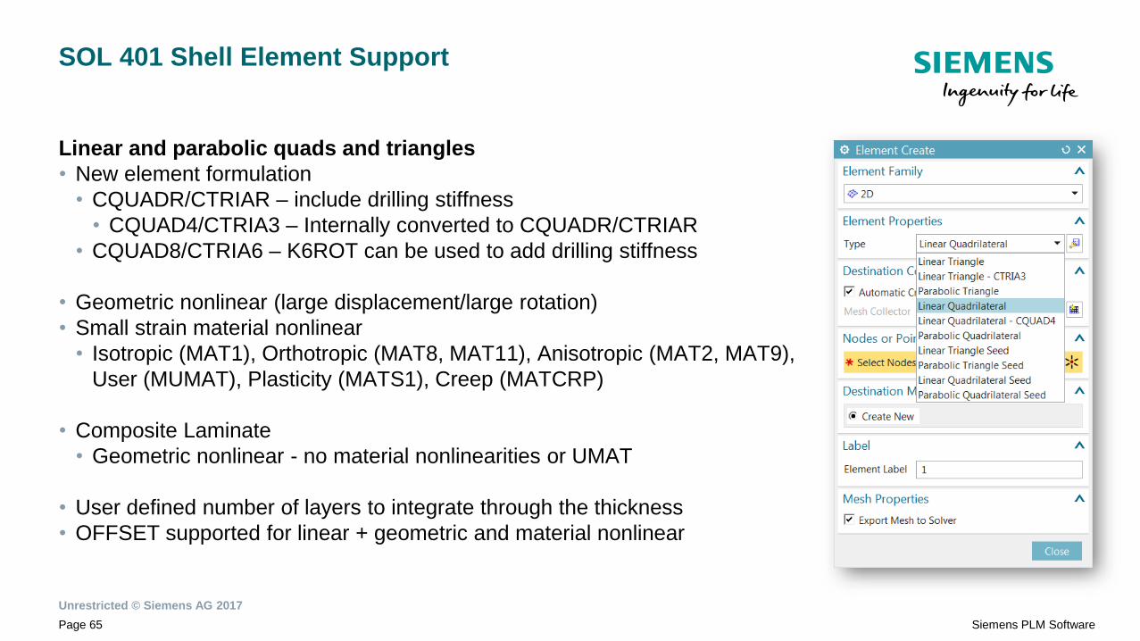
SOL 401 Shell Element Support
Linear and parabolic quads and triangles
• New element formulation
• CQUADR/CTRIAR – include drilling stiffness
• CQUAD4/CTRIA3 – Internally converted to CQUADR/CTRIAR
• CQUAD8/CTRIA6 – K6ROT can be used to add drilling stiffness
• Geometric nonlinear (large displacement/large rotation)
• Small strain material nonlinear
• Isotropic (MAT1), Orthotropic (MAT8, MAT11), Anisotropic (MAT2, MAT9),
User (MUMAT), Plasticity (MATS1), Creep (MATCRP)
• Composite Laminate
• Geometric nonlinear - no material nonlinearities or UMAT
• User defined number of layers to integrate through the thickness
• OFFSET supported for linear + geometric and material nonlinear

Unrestricted © Siemens AG 2017
Page 66 Siemens PLM Software
SOL 401 Beam Element Support
2 noded tension/compression/bending/torsion element definition
• Defined via CBAR/CBEAM
• Existing PBAR/PBARL/PBEAM/PBEAML property definitions
• Geometric nonlinear (large displacement/large rotation)
• End offsets supported
• No material nonlinearities
• Isotropic (MAT1)
• Loads
• Distributed (PLOAD1)
• Can be a follower force if defined in the element coordinate system
• Temperatures (TEMP)
Unrestricted © Siemens AG 2017
Page 67 Siemens PLM Software
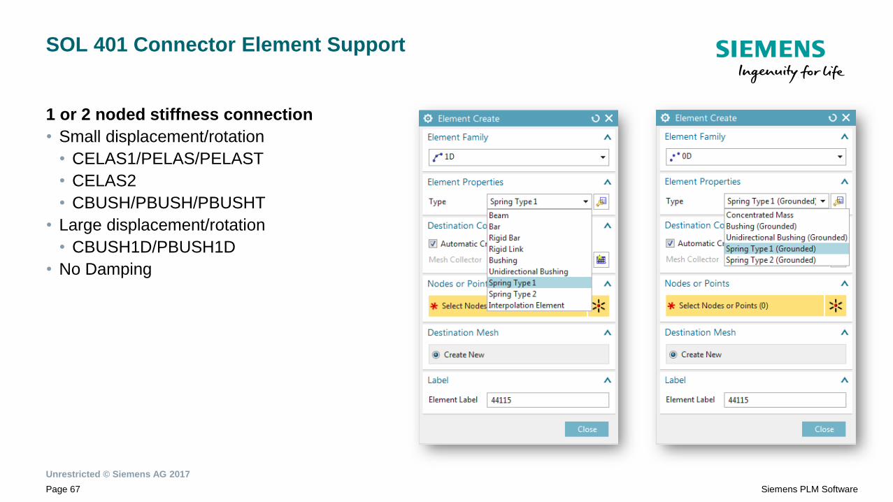
SOL 401 Connector Element Support
1 or 2 noded stiffness connection
• Small displacement/rotation
• CELAS1/PELAS/PELAST
• CELAS2
• CBUSH/PBUSH/PBUSHT
• Large displacement/rotation
• CBUSH1D/PBUSH1D
• No Damping

Unrestricted © Siemens AG 2017
Page 68 Siemens PLM Software
SOL 401 Available in NX Nastran Structural Environment

Unrestricted © Siemens AG 2017
Page 69 Siemens PLM Software
SOL 401 Contact & Glue Improvements
3D shell support in contact & glue regions
Contact behavior types
• Predefined behaviors for normal and traction
• No Sliding
• Bonded/Tied
• No Separation
• Small Sliding
INIPENE Enhancements
• Specify a constant gap to enforce after initial
penetrations and gaps are removed
• Option to ramp the removal of initial geometry
penetrations in preload subcase
Contact Stabilization Damping
Used to stabilize components grounded by contact
prior to contact being fully established
Contact SLIDE output
• Total slide is now the algebraic sum of incremental
slide distance over time
• Resets to 0.0 if a contact element opens, then
closes later

Unrestricted © Siemens AG 2017
Page 71 Siemens PLM Software
Solid Bolt Preload
3D solid / 2D plane stress cut plane formulation for SOL 401
• Allows bolt load definitions to be shared between solutions and
solvers
• Automate determination of bolt plane and axis direction
• CSID and IDIR are optional inputs
• Bolt results output
• Solid bolt results written to any element connected to bolt plane
grids
ETYPE=3 updates
• CSID, IDIR and GP are optional (automatically determined)
BOLTFRC support in linear solution sequences
• Limited to LOAD type
• BOLTFOR will be undocumented (but still recognized)

Unrestricted © Siemens AG 2017
Page 72 Siemens PLM Software
SOL 401 Post-Buckling Analysis
Nonlinear Buckling
Allows analysis of post buckling and snap through
types of problems
• Nonlinear Statics step with zero delta time
• Incremental loads defined in the step are
proportional
• Loads applied in prior steps are held constant
• NLARCL defines arc length control parameters
• Structural only solution (not Coupled)
Initial Imperfection
• An initial imperfection/mesh perturbation can be
defined via IMPERF
• Individual specifications combined via IMPRADD

SOL402

Unrestricted © Siemens AG 2017
Page 82 Siemens PLM Software
NX Nastran SOL402
Introduction
SOL402 – a new NX Nastran solution for advanced nonlinear analysis
Availability through
• NX Nastran Multistep Nonlinear
• Tokens
Main advantages
- Handles large displacements, large rotations, large strains
- Multisteps including dynamic analyses
- Broad range of finite elements
- Nonlinear material laws including hyperelastics and composites

Unrestricted © Siemens AG 2017
Page 83 Siemens PLM Software
NX Nastran SOL402
Targeted markets, industries and applications
Mostly structural aspects, and in particular:
• Bolt tightening (pumps, compressors, …)
• Advanced composite design (e.g. automotive and aerospace)
• Airframe sizing
• Energy dissipation in dampers
Automations of repetitive nonlinear workflows
• Drop simulation (Electronics industry)
• Mechanical industries (compressors, gearings …)
• Engine bearing analysis (Auto industry)
• Seals (aeroengine, mechanical industry, aerospace)

Unrestricted © Siemens AG 2017
Page 84 Siemens PLM Software
NX Nastran SOL402
Simcenter environment
SOL402 is available as an NX Nastran
solution in structural analysis type, and
benefits from following capabilities:
• Import of Nastran decks
• Mesh definition in the FEM file
• Boundary conditions in the SIM file
• Solver syntax preview
• Export and solve
• HPC : DMP and SMP
• Solver monitor with abort and stop (graphs
will be available in 12.0.1)
• Post-processing
…
Time End
subcase
Time
step
size
Convergence criterion
Multiple graphs and MONVAR
in SC12.0.1

Unrestricted © Siemens AG 2017
Page 85 Siemens PLM Software
NX Nastran SOL402
Multistep solution
A unique solution can combine various subcases of the same
type or different types
Eigen mode computation on a pre-stressed
configuration
Available subcases
• Nonlinear statics
• Nonlinear dynamics
• Preload
• Modal
- Normal modes
- Cyclic symmetry
- 2D Multi-Harmonics
• Linear buckling

Unrestricted © Siemens AG 2017
Page 86 Siemens PLM Software
NX Nastran SOL402
Elements for 2D and 3D analyses
Linear and parabolic finite elements
• Solids
- Classical
- Multi-layered composites
- Cohesive elements
• Shells
- Classical
- Multi-layered composites
• Beams and rods
Connectors
• RBE2, RBE3, MPC, CGAP
• Nonlinear springs, bushings, dampers
• CELAS, CBUSH, CDAMP
• Concentrated mass
• CMASS, CONM

Unrestricted © Siemens AG 2017
Page 87 Siemens PLM Software
Comprehensive nonlinear material laws
Isotropic, Orthotropic and Anisotropic
• Linear elasticity and plasticity
- Steel, Aluminium
• Hyperelasticity (Rubbers)
- Damage
- Viscous effects
• Creep
• Composite
- Including damage
• Damage interface
- cohesive zones
Temperature dependencies
NX Nastran SOL402
Materials

Unrestricted © Siemens AG 2017
Page 88 Siemens PLM Software
• Fasteners
• Displacements and rotations
• Velocities
• Accelerations
• Manual coupling (MPCs)
• Initial velocity
Time assigned and time unassigned (step, ramp) paradigms
NX Nastran SOL402
Constraints
Displ P(t)
P1
P2
P3
SC1SC2 SC3
Time

Unrestricted © Siemens AG 2017
Page 89 Siemens PLM Software
Time-assigned and time-unassigned (step, ramp) paradigms
• Forces (including follower)
• FORCE, FORCE1, FORCE2
• Moments (including follower)
• MOMENT, MOMENT1, MOMENT2
• Bolt preloads
• On beams and solid elements
• Apply preloads, strains or displacements
• Pressures
• On faces of solids, shells and beams
• Accelerations (gravity)
• Temperatures
• Uniform distribution
• Mapping of fields
• Imported from SC Thermal
NX Nastran SOL402
Loads

Unrestricted © Siemens AG 2017
Page 90 Siemens PLM Software
• Friction
• Constant, infinite, function of temperature, velocity or time
• Large sliding
• Gap and offset control
• Ignore, eliminate, override initial distance
• Flexible or Rigid targets
• Geometry smoothing option
• Activation/deactivation of contact condition
• Stabilization options
• …
Outputs
• Contact pressures
• Contact forces
• Normal distance
• Sliding
NX Nastran SOL402
Advanced Sliding Contacts

Unrestricted © Siemens AG 2017
Page 91 Siemens PLM Software
Glue
• shell/shell,
• solid/solid,
• solid/shell
Cyclic symmetry
• Support definition
• Harmonic definition
• Recombination in post
NX Nastran SOL402
Glue and cyclic symmetry

Unrestricted © Siemens AG 2017
Page 92 Siemens PLM Software
• Integrate components into full finite element or
hybrid finite element assembly
• Compute full vehicle modes and/or frequency
response functions (FRFs)
Simcenter 12 Structural Dynamics – Solution Focus
• Pre-process and apply loads
• Perform response and contribution analysis on
components or subsystems and on full vehicle
System Level NVH Response Contribution Analysis

Unrestricted © Siemens AG 2017
Page 93 Siemens PLM Software
Modeling Enhancements
• Spot Weld, Seam Weld and Sealing Connections • Bushing, Spring, Damper, Rigid, Kinematic,
Weather Strip, Screw or Bolt connection
Universal Connections for BIW Universal Connections for NVH
Unrestricted © Siemens AG 2017
Page 94 Siemens PLM Software
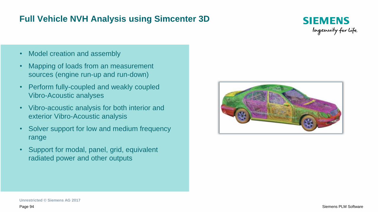
Full Vehicle NVH Analysis using Simcenter 3D
• Model creation and assembly
• Mapping of loads from an measurement
sources (engine run-up and run-down)
• Perform fully-coupled and weakly coupled
Vibro-Acoustic analyses
• Vibro-acoustic analysis for both interior and
exterior Vibro-Acoustic analysis
• Solver support for low and medium frequency
range
• Support for modal, panel, grid, equivalent
radiated power and other outputs

Unrestricted © Siemens AG 2017
Page 95 Siemens PLM Software
Advanced NVH
Reduced Model Representations
• External Superelements
• Hybrid models
• Reduced component representations
• Modal (Test and/or Analytical Modes)
• FRF (Test and/or Analytical FRFs)
Benefits
• Reduced Component Representations.
• OEM / Supplier Data Exchange
• Perform path contributions
ResponsesHybrid or FE
Assembly
Modal
Representation
FE
Representation
Test Modes or
Test FRF
Representation
Loads
(Test)

Unrestricted © Siemens AG 2017
Page 96 Siemens PLM Software
NX Nastran Performance
• Improved Sparse Factorization
• RDMODES support for acoustic modes
• Direct frequency response performance
improvements
0.00
0.20
0.40
0.60
0.80
1.00
Sparse PvL Iterative
Frequency-dependent SOL 108
Normalized Other time
Normalized FRRD fluidtime
0.00
0.20
0.40
0.60
0.80
1.00
Lanczos RDMODES
Fluid-structure coupling SOL 103
Normalized other time
Normalized fluid modetime
Unrestricted © Siemens AG 2017
Page 97 Siemens PLM Software
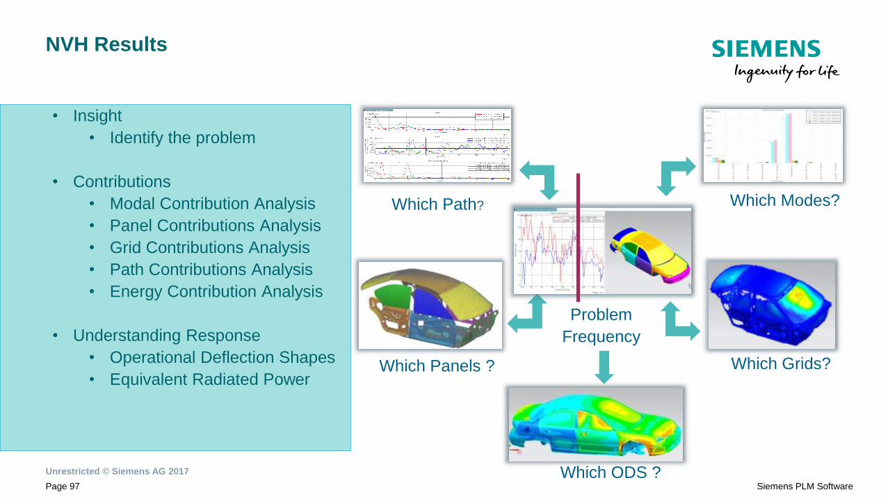
NVH Results
• Insight
• Identify the problem
• Contributions
• Modal Contribution Analysis
• Panel Contributions Analysis
• Grid Contributions Analysis
• Path Contributions Analysis
• Energy Contribution Analysis
• Understanding Response
• Operational Deflection Shapes
• Equivalent Radiated Power
Problem
Frequency
Which Modes?Which Path?
Which Grids?Which Panels ?
Which ODS ?

Unrestricted © Siemens AG 2017
Page 98 Siemens PLM Software
Path Contribution
Force
P/F FRF
Responses

Unrestricted © Siemens AG 2017
Page 99 Siemens PLM Software
Equivalent Radiated Power

Unrestricted © Siemens AG 2017
Page 100 Siemens PLM Software
Energy Contributions
• Energy contributions by sub-assemblies
• Energy contribution by assembly components
• Energy contribution by physical property

Unrestricted © Siemens AG 2017
Page 101 Siemens PLM Software
Contextual Post Processing
Navigator Based Plot Based

Unrestricted © Siemens AG 2017
Page 102 Siemens PLM Software
View Synchronization
Simcenter 3D - Acoustics
What’s New in Release12
Realize innovation.Unrestricted © Siemens AG 2017

Unrestricted © Siemens AG 2017
Page 104 Siemens PLM Software
Vibro-Acoustics Engineering in Simcenter 12
Source – System - Receiver
ReceiverSystemSource
Mechanical Finite Element Vibro-Acoustics
Test-based
Electromagnetics
Boundary Element Vibro-Acoustics
Vibrations Acoustics
Contributions Dynamics stresses
Functions Sensors

Unrestricted © Siemens AG 2017
Page 105 Siemens PLM Software
Simcenter 12 - Source Enhancement
Acoustic sources Acoustic diffuse Field
Random plane wave loads
‘Bread and butter’
acoustic sources:
monopole, dipole,
plane wave, panel vel.
So
urc
e

Unrestricted © Siemens AG 2017
Page 106 Siemens PLM Software
Simcenter 12 - System Enhancements
BE
M
Vib
ro-a
co
us
tic
s
Transfer
admittanceF
EM
vib
ro-a
co
us
tic
s
Transfer Admittance FEMAO ATV
Modal Strongly
CoupledModal Weakly Coupled
Fast Multi-pole & H-
matrix
Sy
ste
m

Unrestricted © Siemens AG 2017
Page 107 Siemens PLM Software
Simcenter 12 - Receiver Enhancements
Scenario postprocessing New plots
Re
ce
ive
r

Unrestricted © Siemens AG 2017
Page 108 Siemens PLM Software
Solutions for Powertrain Acoustics
• Transfer admittance to model perforated
ducts
• TL from post-processing scenario, or from
new NX Nastran cards for incident,
transmitted power and transmission loss
• Shell Noise through VA Response (SC11)
Intake / Exhaust
Muffler Transmission Loss (FEM)
• FEM ATV for fast multi-RPM acoustic
response analysis (beta)
• BEM vibro-acoustic response with structural
mode set
• Can be used for any rotating machinery
Engine and Gearbox
Fast Acoustic radiation
Unrestricted © Siemens AG 2017
Page 109 Siemens PLM Software
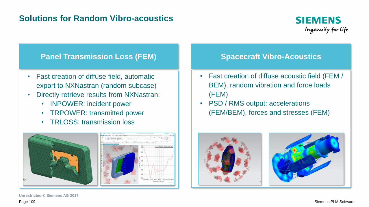
Solutions for Random Vibro-acoustics
• Fast creation of diffuse acoustic field (FEM /
BEM), random vibration and force loads
(FEM)
• PSD / RMS output: accelerations
(FEM/BEM), forces and stresses (FEM)
Spacecraft Vibro-Acoustics
• Fast creation of diffuse field, automatic
export to NXNastran (random subcase)
• Directly retrieve results from NXNastran:
• INPOWER: incident power
• TRPOWER: transmitted power
• TRLOSS: transmission loss
Panel Transmission Loss (FEM)

Unrestricted © Siemens AG 2017
Page 110 Siemens PLM Software
Supporting Higher Frequencies and Larger Geometries
• Two extra solvers: Fast Multipole BEM and
H-matrix BEM (Airbus Group Innovations)
• For mid and high frequency problems and/or
large geometries
• submarine scattering, aircraft ramp noise,…
High frequency audio
Submarine, aircraft scattering
• FEMAO = FEM Adaptive Order
• Faster than standard FEM + constant
(frequency independent) accuracy
• For interior and especially exterior acoustics:
pass-by noise, pedestrian safety warning,
submarine scattering, ..
Pass-by noise
Pedestrian safety warning sounds
Unrestricted © Siemens AG 2017
Page 111 Siemens PLM Software
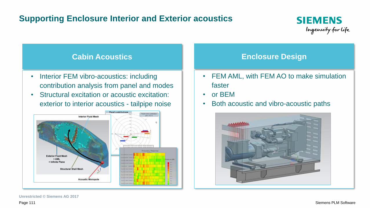
Supporting Enclosure Interior and Exterior acoustics
• Interior FEM vibro-acoustics: including
contribution analysis from panel and modes
• Structural excitation or acoustic excitation:
exterior to interior acoustics - tailpipe noise
Cabin Acoustics
• FEM AML, with FEM AO to make simulation
faster
• or BEM
• Both acoustic and vibro-acoustic paths
Enclosure Design

Simcenter 3D 12What’s New in Thermal & Flow
Unrestricted © Siemens AG 2017 Realize innovation.

Unrestricted © Siemens AG 2017
Page 123 Siemens PLM Software
Introducing Simcenter™ portfolio for
Predictive Engineering Analytics
Simcenter™

Unrestricted © Siemens AG 2017
Page 124 Siemens PLM Software
Simcenter 3D
3D CAE for the digital twin
Linked with system simulation
Multi-discipline integration
Best-in-class simulation modeling
Openness and scalability
Leverage industry expertise

Unrestricted © Siemens AG 2017
Page 125 Siemens PLM Software
Major themes for release
Simcenter 3D
Generative Design Technology Integration Nonlinear Analysis
Industry Workflows

HIGHLIGHTS
Enhanced Temperature-dependent
thermal couplings
Enhanced Orbital Thermal
Analysis
Simcenter 3D Thermal

Unrestricted © Siemens AG 2017
Page 127 Siemens PLM Software
Enhanced Thermal Couplings
Explicitly select
whether primary
region temperature
or average
temperature of both
regions
Primary Region Secondary Region
Explicitly specify
coupling side for thermal
couplings from shell (2D)
meshes
Temperature-dependent
thermal coupling
Unrestricted © Siemens AG 2017
Page 128 Siemens PLM Software
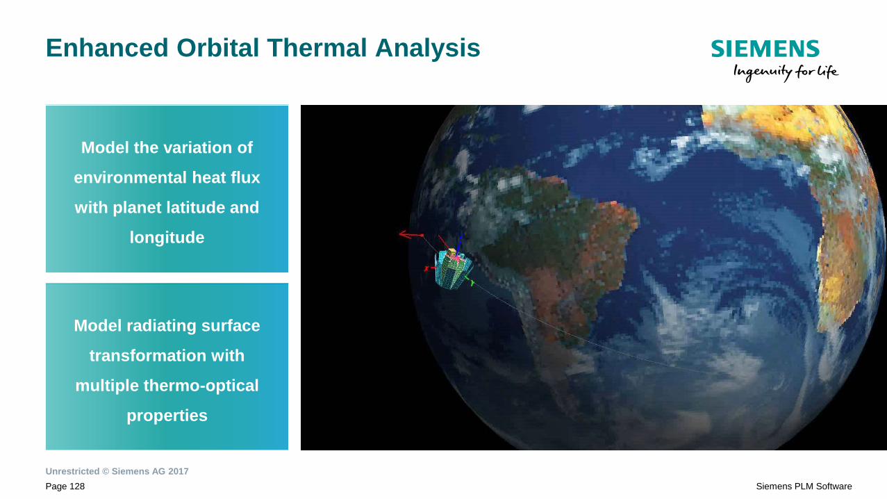
Enhanced Orbital Thermal Analysis
Model the variation of
environmental heat flux
with planet latitude and
longitude
Model radiating surface
transformation with
multiple thermo-optical
properties

HIGHLIGHTS
Enhanced CFD Modeling
Simcenter 3D Flow

Unrestricted © Siemens AG 2017
Page 130 Siemens PLM Software
Enhanced CFD Modeling
Rear of Enclosure
Screen Simulation Object
Front of Enclosure
Pressure drop across screen
between disjoint air meshes
Define screens on disjoint fluid
meshes
Simulate flaps and bursting
membranes
Hybrid wall function
Model mass transport through
semi-permeable membrane

HIGHLIGHTS
Enhanced Surface Wrapping
Simcenter 3D Advanced Fluid
Modeling

Unrestricted © Siemens AG 2017
Page 132 Siemens PLM Software
Enhanced Surface Wrapping
Automatic cavity detection
and wrapping from cavities
Decoupled
surface wrap
resolution
and mesh
density
Automatic
feature edge
detection
Unrestricted © Siemens AG 2017
Page 133 Siemens PLM Software
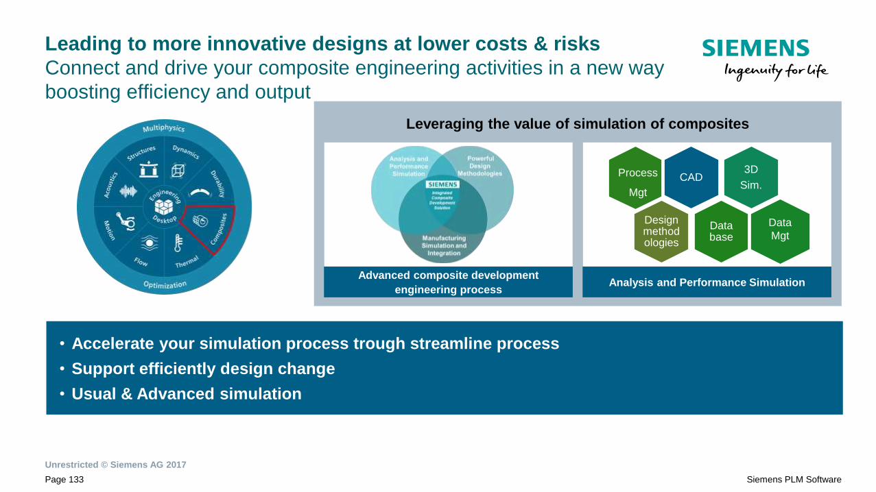
Leveraging the value of simulation of composites
Leading to more innovative designs at lower costs & risks
Connect and drive your composite engineering activities in a new way
boosting efficiency and output
• Accelerate your simulation process trough streamline process
• Support efficiently design change
• Usual & Advanced simulation
Analysis and Performance Simulation Advanced composite development
engineering process
CAD3D
Sim.
Data base
Design methodologies
Data
Mgt
Process
Mgt

Unrestricted © Siemens AG 2017
Page 134 Siemens PLM Software
Simcenter 3D Composite
What’s new in Simcenter 12
Pillars of Highlights
Assembly Label Manager
Build and manage large analysis model assemblies
using a multi-level approach
including composite data
Lay-up Nesting
Support composite assemblies
with multiple mold faces
and dissimilar CAE reference surfaces
Workflow Simplification :
Accelerate and facilitate
the model set up and analysis
Post-processing Scenario
for composite progressive damage simulation
Curing simulation of composites
New workflows support
Woven ply support
Import of CATIA ply groups
Most frequent and common applications Advanced applications

Workflow
acceleration

Unrestricted © Siemens AG 2017
Page 136 Siemens PLM Software
.
Distributed CAE Assembly Model with composite
Laminate Nesting
Agenda
Composite workflow acceleration
Unrestricted © Siemens AG 2017
Page 137 Siemens PLM Software
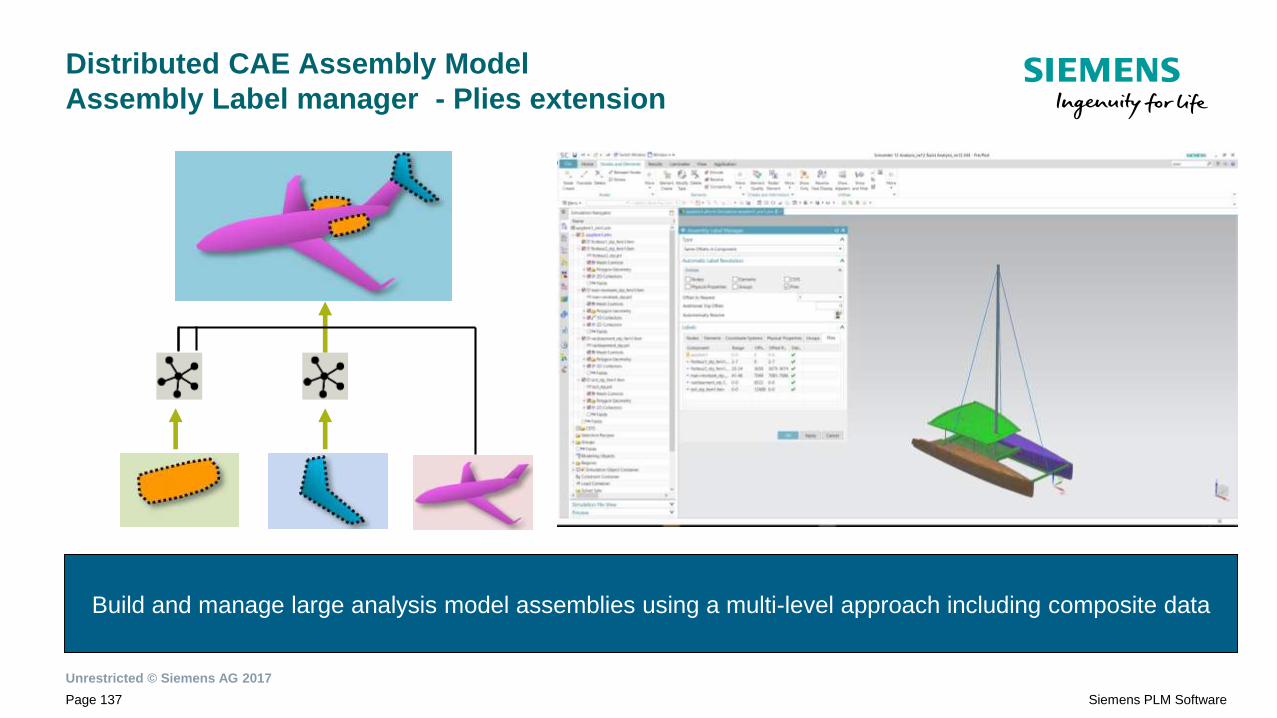
Distributed CAE Assembly Model
Assembly Label manager - Plies extension
Build and manage large analysis model assemblies using a multi-level approach including composite data

Unrestricted © Siemens AG 2017
Page 138 Siemens PLM Software
Distributed CAE Assembly Model
Assembly Label manager - Plies extension
• Relabel composite plies at the assembly level
• Individual FE component model with their own set up of data
• Analyze results components by components
SC11
Display of ply 1 of the full
structure (several plies with
the ID 1)
SC12
Display of ply 1 of one
component of the assembly
Unrestricted © Siemens AG 2017
Page 139 Siemens PLM Software
.
Distributed CAE Assembly Model with composite
Laminate Nesting
Agenda
Composite workflow acceleration

Unrestricted © Siemens AG 2017
Page 140 Siemens PLM Software
Efficient management of global layups
Laminate Nesting support
Efficient composite model management : Support composite assemblies with multiple mold faces and
dissimilar CAE reference surfaces
IMAGE d’un modèle avec plein de sublaminate
• Concatenate several Laminate Nestings
into a single global layup
• Add and manage reinforcements
• Manage a complex composite
assembly made from several cures
with multiple mold faces and
associated laminates
• Support non-manifold CAE geometry

Unrestricted © Siemens AG 2017
Page 141 Siemens PLM Software
Efficient management of global layups
Laminate Nesting support
Base Part
Reinforcement
...in a single layup

Unrestricted © Siemens AG 2017
Page 142 Siemens PLM Software
.
Distributed CAE Assembly Model with composite
Laminate Nesting
Agenda
Composite workflow acceleration

Unrestricted © Siemens AG 2017
Page 143 Siemens PLM Software
Composite workflow improvement
Help the user to accelerate and facilitate the model set up and analysis
SIMCENTER 11
SIMCENTER 12
Laminate composite
advance post report
extension
Laminate modeler &
Draping definition

Unrestricted © Siemens AG 2017
Page 144 Siemens PLM Software
Composite workflow improvement
Projection solver
The ply’s primary direction can be defined:
• From the element’s material orientation (SC11)
• Using a CSYS (in SC12)
Simcenter-centric Edit in Excel now
replaces tedious import and export of plies
Select a coordinate system
to display SC12

Advanced
applications
Unrestricted © Siemens AG 2017
Page 146 Siemens PLM Software
.
Woven material
Curing analysis extension
Agenda
Post-processing scenario for damage analysis
CATIA ply groups

Unrestricted © Siemens AG 2017
Page 147 Siemens PLM Software
Improved Woven Material Model
• The most basic properties of a woven ply material will
change as the angle between the warp and weft fibers
varies
• For example, by laying the fabric on a doubly-curved surface
• This shearing effect is not considered in typical material
characterization efforts
• Strength knockdown factors are typically applied, which can be
overly conservative
Increase your simulation accuracy by taking into account the woven fiber shear
Unrestricted © Siemens AG 2017
Page 148 Siemens PLM Software
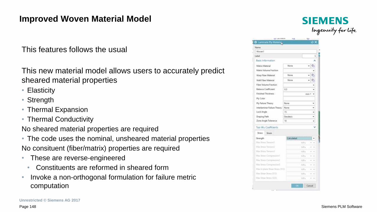
Improved Woven Material Model
This features follows the usual
This new material model allows users to accurately predict
sheared material properties
• Elasticity
• Strength
• Thermal Expansion
• Thermal Conductivity
No sheared material properties are required
• The code uses the nominal, unsheared material properties
No consituent (fiber/matrix) properties are required
• These are reverse-engineered
• Constituents are reformed in sheared form
• Invoke a non-orthogonal formulation for failure metric
computation

Unrestricted © Siemens AG 2017
Page 149 Siemens PLM Software
.
Woven material
Curing analysis extension
Agenda
Post-processing scenario for damage analysis
CATIA ply groups
Unrestricted © Siemens AG 2017
Page 150 Siemens PLM Software
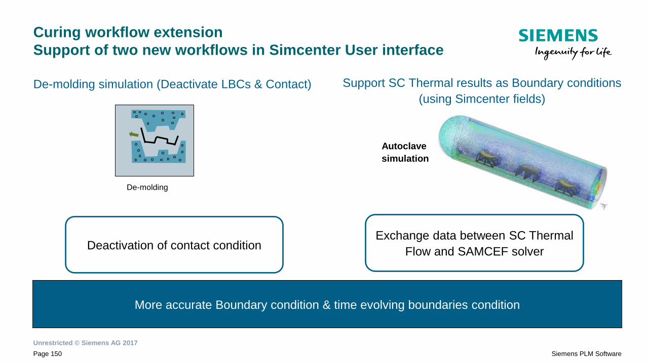
Curing workflow extension
Support of two new workflows in Simcenter User interface
De-molding simulation (Deactivate LBCs & Contact)
De-molding
Support SC Thermal results as Boundary conditions
(using Simcenter fields)
Autoclave
simulation
More accurate Boundary condition & time evolving boundaries condition
Exchange data between SC Thermal
Flow and SAMCEF solver Deactivation of contact condition

Unrestricted © Siemens AG 2017
Page 151 Siemens PLM Software
.
Woven material
Curing analysis extension
Agenda
Post-processing scenario for damage analysis
CATIA ply groups
Unrestricted © Siemens AG 2017
Page 152 Siemens PLM Software
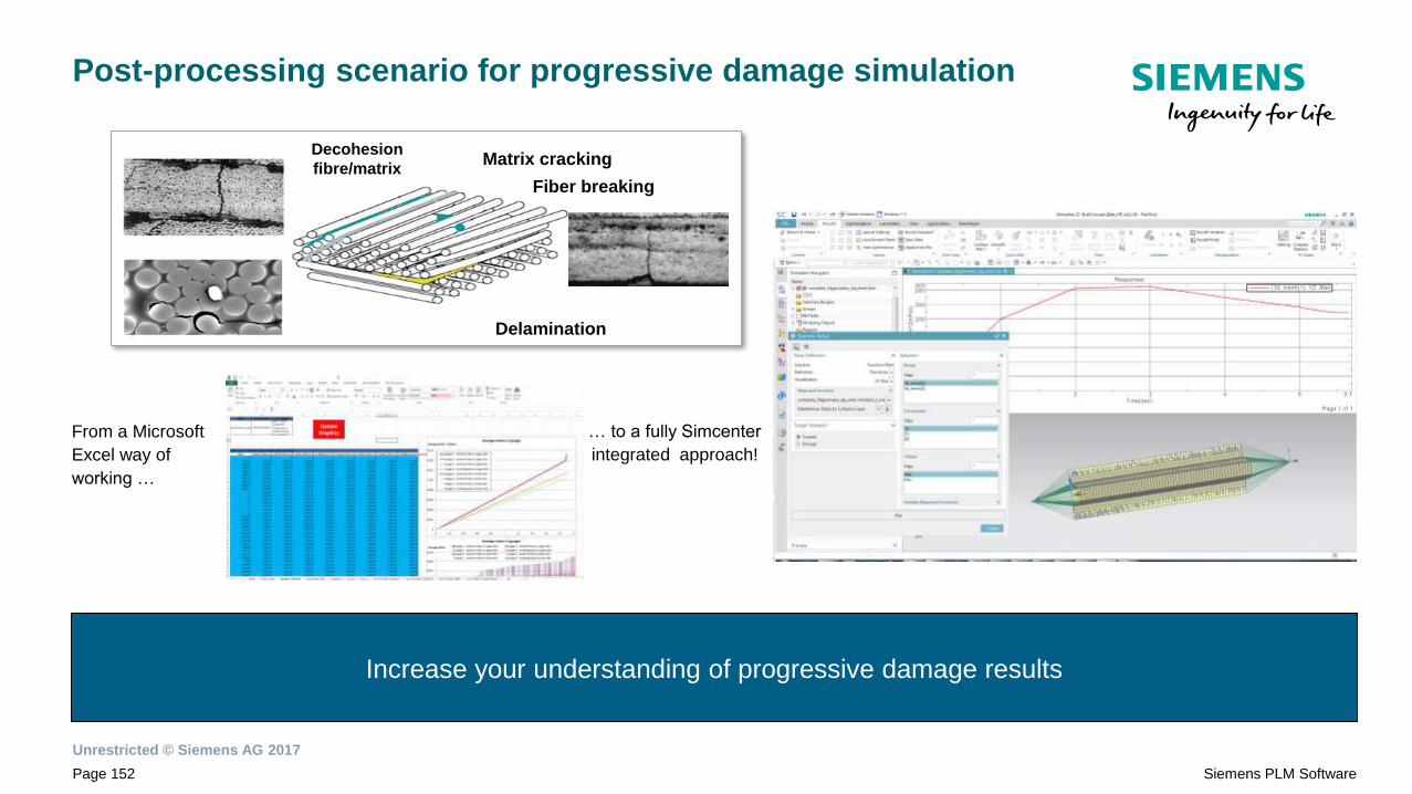
Post-processing scenario for progressive damage simulation
Increase your understanding of progressive damage results
From a Microsoft
Excel way of
working …
… to a fully Simcenter
integrated approach!
Fiber breaking
Matrix cracking
Delamination
Decohesion
fibre/matrix

Unrestricted © Siemens AG 2017
Page 153 Siemens PLM Software
.
Woven material
Curing analysis extension
Agenda
Post-processing scenario for damage analysis
CATIA ply groups
Unrestricted © Siemens AG 2017
Page 154 Siemens PLM Software
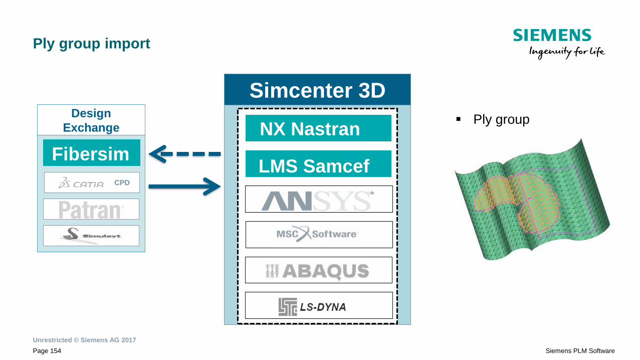
Ply group import
Simcenter 3DDesign
Exchange
CPD
▪ Ply group NX Nastran
LMS SamcefFibersim

Solver specific

Unrestricted © Siemens AG 2017
Page 156 Siemens PLM Software
Simcenter 3D
Siemens Finite Element support for composite
Analysis
capabilitiesSamcef solver
NX
NASTRAN
SC
Response
Dynamics
SC
Laminate
Composites
Dynamics
Linear
Linear static ● ●
Buckling ● ●
Modal ● ●
Harmonic ● ●
Transient ●
Random ● ● ●
Nonlinear
Static ● ●
Quasi-static
Transient kinematic
Transient dynamic
(implicit)
Progressive Damage
Simulation
Damage interface ● ●
Damage ply ● ●
Damage coupling (interface&
ply) ●
Curing ●
Genera
l fe
atu
res
Specific
app.

Unrestricted © Siemens AG 2017
Page 157 Siemens PLM Software
New in Simcenter 3D release 12
NX Nastran SOL402: Advanced Nonlinear NX Nastran Solution
• 3D – Plane stress – Plane strain –
Axisymmetric
• Multistep – NL Statics, NL Dynamics,
Modal, Preload, Buckling
• Import, export of bulk data files
• Nastran OP2 result files
• Post-processing in Simcenter
• Nonlinear materials including composite
• Solids, shells, beams
• Loads and constraints
• Contact, gluing, bolts
Included in Simcenter 12
NX Nastran environment
Advanced Nonlinear
Solution
Post-processing in
Simcenter

Unrestricted © Siemens AG 2017
Page 158 Siemens PLM Software
New Solver Support
SOL401 & SOL402 : Composite support
• PCOMP: laminate definition
• PCOMPS: laminate for solids
• PCOMPG: global ply definition
• PCOMPG1: global ply definition specific for SOL401 and SOL402
• CHEXCZ, CPENTCZ: specific elements for cohesive zones
• PSOLCZ: properties for cohesive elements
• MATCZ: material properties for cohesive elements: Polynomial, bitriangular or
exponential laws
• MATDMG: Damage material properties: UD or EUD
• MATFT: ply failure theory (Hill, Hoffman, Tsai wu, max strain, max stress, max
shear stress)
• PFRESULTS: results for damage
• CZRESULTS: results for cohesive elements

Unrestricted © Siemens AG 2017
Page 159 Siemens PLM Software
Simcenter Laminate Composites Dynamics
Base-driven random
simulation
Peak ply stresses, strains
Peak ply failure metrics
Specify desired confidence
NX Nastran failure theories
2D and 3D laminates
Parallelized solver
High-performance integration
algorithm
• Base-driven harmonic
simulation
• Efficient analytical
computation of phase-
consistent results
• Ply failure metrics
• Von Mises stress
• Peak results over entire
frequency range
• Parallelized solver
Simulate shaker testing with best-in-class performance and accuracy

Unrestricted © Siemens AG 2017
Page 160 Siemens PLM Software
Samcef solver and Samcef environment in SC12 enhancements
Highlight (on the top of already explained)
• New Finite element support Solid Ply :
• Support of new first ply failure criteria LARC04 :
• based on physical models for each failure mode and distinguish between fiber and matrix
failure for different transverse fiber and matrix tension and compression modes
• Import an existing solver deck with composite and recreate a Simcenter session
• Performance improvement of the solver deck generation
• Performance improvement in post processing support
Solver
Samcef
env.• Several planes
• Multiple solution
support
• Convert from Nastran, Ansys,
• Recovery result
• Static / Dynamic SE
2D Analysis : Axi-symmetric; Plane
Stress; Plane Strain
External Superelement support in
Assembly FEM
Unrestricted © Siemens AG 2017
Page 161 Siemens PLM Software
Serkan Us
INORES
E-mail:[email protected]
Teşekkürler…
Kayıt için inores.com/iletisim