sime format boilers - belle comfort format wall hung boilers model 34i and model 34e ref:...
TRANSCRIPT

SIME FORMAT WALL HUNG BOILERS MODEL 34i AND MODEL 34e cod. 6272262A

SIME FORMAT WALL HUNG BOILERS MODEL 34i AND MODEL 34e
REF: INSTALLATION INSTRUCTIONS 19/02/04 2
GENERAL DATA – Heating Data Heat Output Input
(Adjustable) (Adjustable) Format 34i 11.2 – 34KW 45 – 145MJ/hr
Format 34e 11.2 – 34KW 45 – 145MJ/hr
– General Specifications FORMAT 34i – 34e Main burner injectors No off 15
Dia for Natural gas mm 1.45
Dia for LPG mm 0.85
Water Capacity l(gal) 4.7 (1.00)
Burner pressure Natural gas Maximum kPa 0.71kPa
Minimum kPa 0.09kPa
Burner pressure LPG (Propane) Maximum kPa 2.41 kPa
Minimum kPa 0.50 kPa
Static head Maximum bar (psi) 3.0 (43.5)
Minimum bar (psi) 0.5 (7.3)
Weight Empty kg (lb) 40 (88)
Total (full) kg (lb) 44.7 (98)
Electrical supply 230V – 50Hz, Fused at 3A
Internal fuse Line: F 1.6A
Maximum power consumption Watt 160
Maximum gas consumpt. (Natural gas) m³/h 3.68
Maximum gas consumpt. (Propane) kg/h 2.74 – 2.70
Max. working temperature °C (F) 95 (203)
Integral exp. Vessel capacity L (gal) 8 (1.76)
TABLE 4 Gas Supply Min. Pressure Max. Pressure Natural Gas 0.09kPa 0.71kPa Propane Gas 0.50kPa 2.41kPa Nominal Gas Consumption 145 mj/h

SIME FORMAT WALL HUNG BOILERS MODEL 34i AND MODEL 34e
REF: INSTALLATION INSTRUCTIONS 19/02/04 3
Fig. 1
Connections Minimum clearances For ventilation For servicing
R C.H. return ¾
Above the appliance casing 450mm 300mm
M C.H. flow ¾ At the R.H.S. 15mm 15mm
G Gas connection ¾ At the L.H.S. 15mm 15mm
C Filling Connection ½ Below the appliance casing 200mm 200mm
In front of the appliance 100mm 500mm

SIME FORMAT WALL HUNG BOILERS MODEL 34i AND MODEL 34e
REF: INSTALLATION INSTRUCTIONS 19/02/04 4
SIME FORMAT WALL HUNG BOILERS
MODEL 34i, MODEL 34e CENTRAL HEATING BOILERS
INSTALLATION INSTRUCTIONS INTRODUCTION These instructions cover the installation of the SIME FORMAT 34i, an internally mounted boiler using a co-axial flue system, and the SIME FORMAT 34e, an externally mounted boiler. They are fully automatic in operation, being fitted with direct fired ignition, modulating temperature control and safety control by means of electronic and electro-mechanical devices, integrated with a custom-designed P.C.B.. The central heating output range is adjustable between 11.2 KW and 34 KW. NOTE: THE BOILER IS NOT TO BE USED FOR POOL OR SPA
HEATING. THE BOILER MUST BE INSTALLED ONLY BY AN
AUTHORISED PERSON 1.0 GENERAL INFORMATION
1.0.1 Related Documents
The boilers must be installed strictly in accordance with these Instructions, the Australian Gas Association “Gas Installation Code” AG601, Local Water and Electricity Authority Requirements and all State and Local Government Regulations which may be applicable. 1.0.2 Delivery Check
The Installer shall, upon delivery, immediately remove all packaging materials, and inspect the appliance for any damage, and ensure that the boiler is equipped for the gas to which it is to be connected. Report to the supplier any discrepancies and / or damage, quoting the model number and serial number, which can be found on the appliance Data Plate.

SIME FORMAT WALL HUNG BOILERS MODEL 34i AND MODEL 34e
REF: INSTALLATION INSTRUCTIONS 19/02/04 5
Fig. 2
KEY 1. Control panel 2. Ignition transformer 3. Combustion chamber 4. Fan 5. Combustion analysis intakes 6. Smoke pressure switch 7. Limit thermostat 8. C.H. sensor (SM) 9. Main exchanger 10. Gas valve 11. Flow water switch 12. 102°C resettable safety stat

SIME FORMAT WALL HUNG BOILERS MODEL 34i AND MODEL 34e
REF: INSTALLATION INSTRUCTIONS 19/02/04 6
Fig 3.
Key
1. Fan 11. Circulation Pump 2. Water-gas exchanger 12. Expansion Vessel 3. Combustion chamber 13.Safety Valve 4. Gas Valve 14. Drain Plug 5. Limit thermostat 85o C 15. Automatic By-pass 6. 102o C safety Thermostat C. Filling Connection 7. NTC sensor G. Gas Connection 8. Hydrometer M. C.H.Flow 9. Water Flow Switch S. Discharge Safety Valve 10. Air Relief Valve R. C.H.Return

SIME FORMAT WALL HUNG BOILERS MODEL 34i AND MODEL 34e
REF: INSTALLATION INSTRUCTIONS 19/02/04 7
2.0 INSTALLATION
2.1 Location
2.1.1 Model 34i a) The boiler must be installed within the building.
b) The boiler must be installed on a flat vertical surface which
is capable of supporting the weight of the filled boiler.
c) The location must take account of the flueing method to be used and the position of the external flue terminal with regard to the requirements of AG601. Flue terminals must terminate outside.
2.1.2 Model 34e
a) The boiler must be installed on the outside of the building.
b) The location must take account of the position of the flue with regard to the requirements of AG601.
2.2 Clearances
2.2.1 Model 34i a) There must be a minimum clearance of 450mm between
the top edge of the boiler and any horizontal surface above the boiler. Any regulations with regard to combustible surfaces and suitable fire protection must be observed.
b) A minimum clearance of 15mm must be provided between
the side of the boiler and any adjacent wall.
c) A clear space of at least 600mm must be provided in front of the boiler, for user access to the controls, and for service purposes.
d) The location must take account of the requirements of AG601
2.2.2 Wall Fixing
Mounting Bracket. a) The Boiler is located on the wall using the bracket (see
Fig.4). This bracket should be located horizontally, between 1.70 – 1.85 meters above the ground.
SIME FORMAT WALL HUNG BOILERS MODEL 34i AND MODEL 34e
REF: INSTALLATION INSTRUCTIONS 19/02/04 8
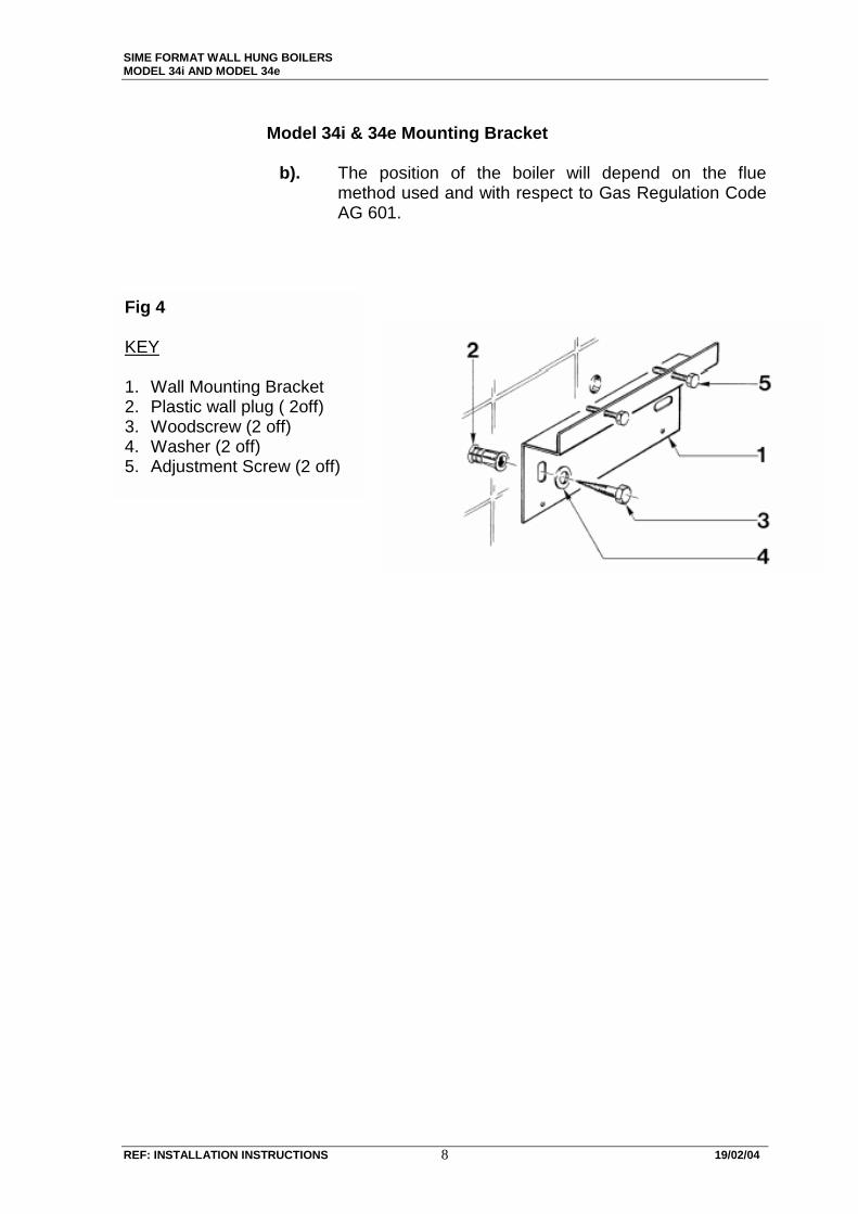
Model 34i & 34e Mounting Bracket
b). The position of the boiler will depend on the flue
method used and with respect to Gas Regulation Code AG 601.
Fig 4 KEY 1. Wall Mounting Bracket 2. Plastic wall plug ( 2off) 3. Woodscrew (2 off) 4. Washer (2 off) 5. Adjustment Screw (2 off)
SIME FORMAT WALL HUNG BOILERS MODEL 34i AND MODEL 34e
REF: INSTALLATION INSTRUCTIONS 19/02/04 9
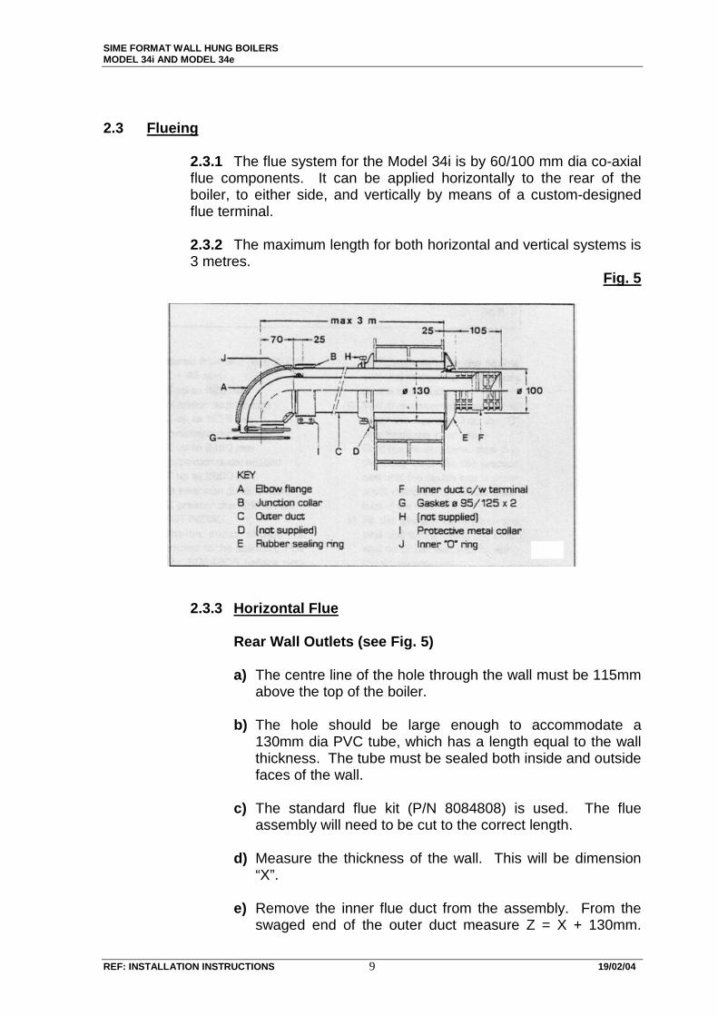
2.3 Flueing 2.3.1 The flue system for the Model 34i is by 60/100 mm dia co-axial
flue components. It can be applied horizontally to the rear of the boiler, to either side, and vertically by means of a custom-designed flue terminal.
2.3.2 The maximum length for both horizontal and vertical systems is
3 metres. Fig. 5
2.3.3 Horizontal Flue Rear Wall Outlets (see Fig. 5) a) The centre line of the hole through the wall must be 115mm
above the top of the boiler. b) The hole should be large enough to accommodate a
130mm dia PVC tube, which has a length equal to the wall thickness. The tube must be sealed both inside and outside faces of the wall.
c) The standard flue kit (P/N 8084808) is used. The flue
assembly will need to be cut to the correct length. d) Measure the thickness of the wall. This will be dimension
“X”. e) Remove the inner flue duct from the assembly. From the
swaged end of the outer duct measure Z = X + 130mm.

SIME FORMAT WALL HUNG BOILERS MODEL 34i AND MODEL 34e
REF: INSTALLATION INSTRUCTIONS 19/02/04 10
Cut square at this dimension and remove all burrs and sharp edges.
f) Refit the inner duct (see Fig. 6) and cut square this duct
20mm longer than the outer duct. Remove all burrs and sharp edges.
Fig 6
g) Fit outer seal in the swage next to the terminal, and slide the assembly through the wall to clear the outer seal. Fit the inner seal and junction collar to the outer duct.
h) Ensure that the sealing ring is in place in the elbow and fit
inner duct and outer duct to the elbow. i) Locate the joining clamp and tighten, using screws
provided. j) Locate the gasket in the boiler flue outlet and pull back
assembly to locate the elbow. Fit four (4) screws provided and tighten.
2.3.4) Side Wall Outlets a) Extension ducts are available for this application. The flue
elbow should be fitted to the boiler. b) In this case, the cut length of the outer duct Z = X + Y + 20.
Where X = wall thickness Y = distance from inner face of the wall to the front edge of the elbow. c) It is recommended that, to drain any condensate, a fall of
5mm/meter length be provided.

SIME FORMAT WALL HUNG BOILERS MODEL 34i AND MODEL 34e
REF: INSTALLATION INSTRUCTIONS 19/02/04 11
2.4 Vertical Installation (see Fig. 7.)
Fig 7
2.4.1 Vertical installation a) requires a 200mm long adaptor (P/N 8086903A) be fitted to the outlet flange
of the boiler. Vertical roof terminal (P/N 8091200) is used. Extension ducts are available when required. The same principles with regard to duct length, and the removal of burrs and sharp edges are applicable. Extensions P/N 8084804.
2.5 Gas Connection
2.5.1 The gas connection is made to a G¾” male thread on the centre line of the boiler (see Fig.1). It is recommended that a manual shut-off valve is installed adjacent to the inlet connection in accordance with the provisions of AG 601.
2.5.2 Gas fitting lines must be designed and installed in accordance
with the requirements of AG601, to which reference should be made for pipe sizing information.
2.5.3 Piping MUST be sized so that a minimum pressure of 1.13kPa
for Natural Gas and 2.75kPa for Propane is measured at the gas control inlet test point WHEN THE BOILER IS OPERATING AT ITS MAXIMUM INPUT RATE.
2.5.4 For Propane, the second stage regulator should have a
minimum capacity in accordance with the provisions of AG 601.
Important! Each additional 90˚ elbow reduces the available length by 0.9 meters.

SIME FORMAT WALL HUNG BOILERS MODEL 34i AND MODEL 34e
REF: INSTALLATION INSTRUCTIONS 19/02/04 12
2.6 Central Heating Connection
a) Before any connection of the central heating system is made to the boiler, the system should be thoroughly flushed through to remove any dirt and foreign matter which could damage the pump and other devices in the boiler.
b) The connection to the boiler are by G¾” male threads.
c) When an auto-fill valve is used, it must be installed to the cold
fill inlet. It is recommended that after filling the boiler and adjusting the pressure setting, the manual shut-off valve be closed. It is also recommended that a manual shut off valve be installed before the AFV for maintenance purposes.
d) The system should be filled to a cold static pressure of 1.5 bar,
filling to be carried out slowly and all air bled from the system. Should the system pressure drop below 0.8 bar, the boiler will not operate until the pressure is restored to 1.5 bar.
e) The drain pipe from the 3 Bar pressure relief valve in the boiler
must terminate in such a position that any discharge is visible to the user. (See Fig 3)
f) The boiler is provided with an automatic by-pass, which
operates on systems fitted with thermostatic radiator valve. g) The condition of the water in the system is of great importance.
Treatment, such as Fernox, is recommended, to reduce the effect of sludge and scale on the efficiency of the heating system.
h) For installations where the heater is connected to larger
systems, the additional volume will need to taken into account. A temperature pressure relief valve may be needed for such installations.
2.7 Electrical Connection a) The electrical connection is made to a standard 10amp 3 pin
outlet. It is essential that a positive earth be made for the satisfactory operation of the boilers.
THIS MUST BE FITTED BY A QUALIFIED ELECTRICIAN
b) The room thermostat is connected to terminals 2 & 4 in the control box (see note on Fig. 9.) The thermostat must be capable of operating 240V AC, and the relative wiring should also be the same.

SIME FORMAT WALL HUNG BOILERS MODEL 34i AND MODEL 34e
REF: INSTALLATION INSTRUCTIONS 19/02/04 13
3.0 OPERATION
a) The boiler is controlled by a PCB located in the control box. A potentiometer on the PCB, together with a thermistor located on the heat exchanger outlet, controls the temperature of the circulating water, by modulating the gas pressure.
. The control box also contains the operation selector switch (B),
which has OFF, ON and RESET positions.
a) OFF will turn the boiler OFF.
b) ON will start and run the boiler.
c) RESET is a momentary-on operation, which will reset the ignition sequence, should the boiler shut down with lockout.
d) Central Heating Temperature adjusting knob (A)
Two indicator lights are positioned to the right of the Selector Switch.
These indicate fault and reset functions (see Fig. 8).
Fig 8
SIME FORMAT WALL HUNG BOILERS MODEL 34i AND MODEL 34e
REF: INSTALLATION INSTRUCTIONS 19/02/04 14
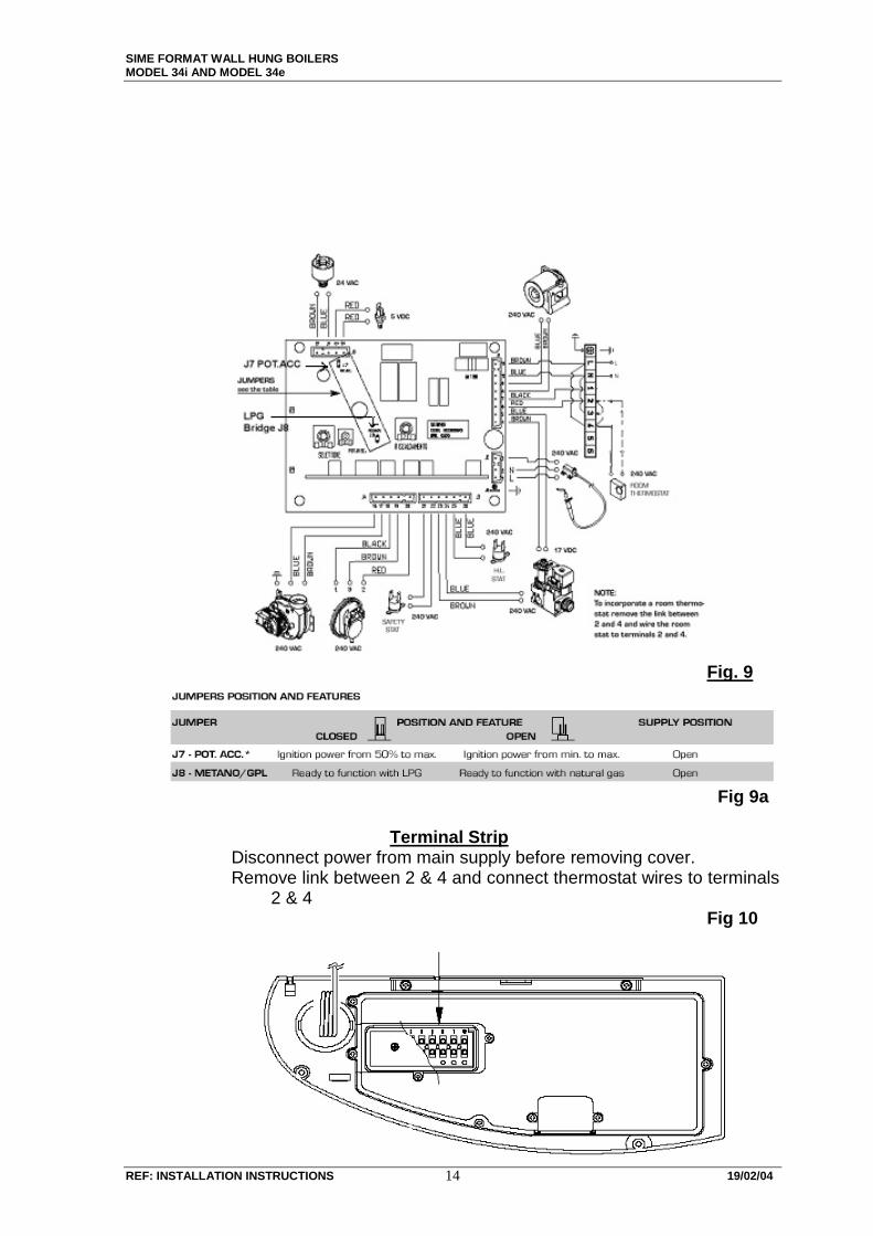
Fig. 9
Fig 9a
Terminal Strip
Disconnect power from main supply before removing cover. Remove link between 2 & 4 and connect thermostat wires to terminals
2 & 4 Fig 10

SIME FORMAT WALL HUNG BOILERS MODEL 34i AND MODEL 34e
REF: INSTALLATION INSTRUCTIONS 19/02/04 15
3.2 PCB Features
a) POT.ACC. Bridge.( see Fig 9) This modifies the ignition pressure programme of the gas valve. With the bridge disconnecting, the ignition pressure varies in a linear manner from low to the maximum set heating pressure. With the bridge connected, the pressure varies in a linear manner from 50% to the maximum set heating pressure.
When the boiler is operating on Propane, it is recommended that the bridge be connected to improve the ignition function (quicker cross-lighting) ( see Fig 9a).
b) Natural Gas/ LPG Selector Bridge. With the bridge disconnected, the boiler will operate correctly for Natural Gas. With the bridge connected, the boiler will operate correctly for LPG gas. Failure to use in the correct position for either gas will mean that the required maximum and minimum gas pressure cannot be obtained.
3.3 Temperature Control Temperature control is provided by modulation of the gas burner
pressure, and thus the input of the boiler. The water temperature is sensed by N.T.G. thermistor located on the outlet of the heat exchanger. The varying voltages thus produced by the PCB will operate the modulating coil on the gas valve, and move the servo regulator accordingly.

SIME FORMAT WALL HUNG BOILERS MODEL 34i AND MODEL 34e
REF: INSTALLATION INSTRUCTIONS 19/02/04 16
3.4 Limit Switches The boiler is fitted with two limit switches.
(a) Switch located on the heat exchanger, 85º, will turn the boiler OFF, without lockout. It will reset when the temperature drops by 2ºC.
(b) Switch located on the C.H. flow pipe, behind the control box, 100ºC, will turn the boiler OFF with lockout. A complete manual restart is necessary.
Fig 11
To reset the overheat thermostat The appliance is fitted with a safety cut-out thermostat in the event of overheating this will interrupt the power supply and prevent the appliance from functioning. If this occurs, allow the appliance to cool, reinstate the thermostat button as shown in figure 11, turn
the rotary switch to “ “ position until both leds on the facia panel flash; then turn it back to the previous position. If the cut-out condition is repeated, turn off the electrical supply and consult your installer or service engineer.

SIME FORMAT WALL HUNG BOILERS MODEL 34i AND MODEL 34e
REF: INSTALLATION INSTRUCTIONS 19/02/04 17
4.0 COMMISSIONING
Preliminary Checks
a) Ensure that the central heating system is full of water and that the pressure gauge indicates a cold static pressure of 1 – 1.5 bar.
b) Ensure that all air has been bled from the system and all air vents
are closed.
c) Ensure that all heat emitter valves are open, and that all thermostatically operated radiator valves are fully open.
d) Ensure that the boiler is connected to the gas supply for which it
has been assembled, and that the gas line has been purged of air up to the gas control inlet.
e) Ensure that the electricity supply is correctly connected, and that a
positive earth connection is provided.
f) Ensure that no flammable liquids or materials are in contact with or are in the immediate vicinity of the boiler.
OPERATION
a) Ensure that the gas supply is turned ON and that electrical supply is turned ON.
b)Turn the temperature control knob to maximum.
c)Turn the room thermostat on.
d) Turn the Selector Knob to the ON position, indicated by a star. A green light will then appear on the front panel.
e) The pump will start and run for approximately 60 seconds.
f) The boiler will then commence the ignition start-up sequence, and
will modulate to the maximum set input.
g) Turn the temperature control knob to the desired position. The boiler will now heat the system water to the set temperature and continuously modulate to maintain that temperature.
ADJUSTMENTS
a) The PCB operates two colour LED’s one is bi-colour, green and orange, the other is red. The green indicates power ON,

SIME FORMAT WALL HUNG BOILERS MODEL 34i AND MODEL 34e
REF: INSTALLATION INSTRUCTIONS 19/02/04 18
Fig12
steady orange indicates a faulty CH sensor, and flashing orange indicates low water pressure. The red indicates lockout. Other features available of the PCB are:-
b) POT ACC trimmer, (Fig.12), used to set the ignition power from min. to max.
c) MET-GLP Bridge (Fig.12), used to set the PCB for either NG or LPG usage.
4.1 Gas Valve
a) The SIT 845 SIGMA is fitted with a continuously modulating Zero regulator, having two definite pressure settings. These pressures, shown in Table 4 for both Natural Gas and Propane usage, are factory set for the gas supply to which the boiler is to be connected. There should not be any need other than the field conversion from one gas to another or the exchange of a gas valve, for these to be adjusted. In the case of the above exceptions, or if it is obvious that adjustment is necessary, the following procedures are to be followed. It is important to note that, the maximum pressure is to be set first, followed by the minimum, to the pressure indicated in Table 4 for the gas used. All adjustments are made with the CH adjusted set fully clockwise, and the temperature knob at maximum.

SIME FORMAT WALL HUNG BOILERS MODEL 34i AND MODEL 34e
REF: INSTALLATION INSTRUCTIONS 19
Pressure Adjustment SIT 845 Sigma (see Fig.13) Setting the Maximum Pressure (a) Connect the pressure gauge as shown in Fig. 13. (b) Remove the plastic cap. (c) Turn the rotary switch to ON, and ensure that the room
thermostat is calling for heat. Turn the C.H. thermostat to maximum and the boiler will light.
(d) Using a 10mm spanner, turn nut 3 clockwise to increase
counter clockwise to decrease to arrive at the pressure shown in Table 4.
Setting the Minimum Pressure (a) Turn Boiler off and disconnect one lead to the modulating
coil. (b) Turn Boiler on and using a Phillips head screwdriver
turn clockwise to increase, counter clockwise to decrease to the pressure as shown in Table 4.
(c) Operate the main switch a number of times and check
that the pressure corresponds to the pressures in Table 4 (d) Replace the lead to the modulating coil and the plastic
cap.
KEY 1. Plastic Cap 2. Minimum Pressure adjusting screw 3. Maximum Pressure adjusting Nut 4. Sime pressure manometer 5. Burner test point
19/02/04
Fig. 13

SIME FORMAT WALL HUNG BOILERS MODEL 34i AND MODEL 34e
REF: INSTALLATION INSTRUCTIONS 19/02/04 20
TABLE 4 Gas Supply Min. Pressure Max. Pressure Natural Gas 0.09kPa 0.71kPa Propane Gas 0.50kPa 2.41kPa Nominal Gas Consumption 145 mj/h
4.3 Adjusting the Heat Output
The boiler is supplied with the C.H. output set to maximum. The Tables, Fig.14a & Fig. 14b, show the output (pressure requirements of both Natural Gas and Propane. To adjust the CH output/pressure, the following procedure is used:-
(a) Consult the appropriate table for the relative gas, and
establish the required pressure. (b) Connect the manometer to position 5 as shown in
Fig.13. (c) Heat the boiler by turning the Selector Knob to the ON
position. (d) Turn the temperature control knob to maximum, and
remove the knob as shown in Fig.12. (e) Using a small screwdriver, access the trimmer inside the
hole marked “B”. Turn carefully clockwise to increase, counter clockwise to decrease the pressure.
(f) Turn the selector knob off and on several times to
ensure that the set pressure is stable. (g) Replace knob, and set to required temperature.
FIG 14
SIME FORMAT WALL HUNG BOILERS MODEL 34i AND MODEL 34e
REF: INSTALLATION INSTRUCTIONS 19/02/04 21
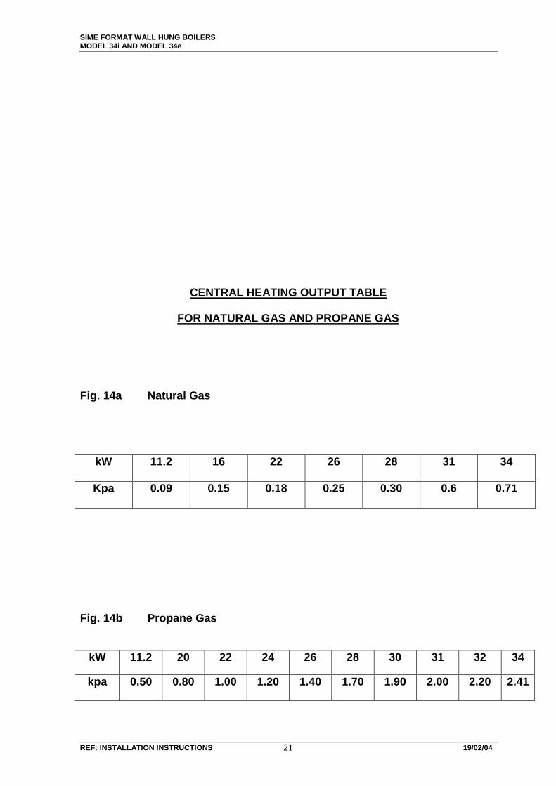
CENTRAL HEATING OUTPUT TABLE
FOR NATURAL GAS AND PROPANE GAS Fig. 14a Natural Gas
Fig. 14b Propane Gas
kW 11.2 20 22 24 26 28 30 31 32 34
kpa 0.50 0.80 1.00 1.20 1.40 1.70 1.90 2.00 2.20 2.41
kW 11.2 16 22 26 28 31 34
Kpa 0.09 0.15 0.18 0.25 0.30 0.6 0.71

SIME FORMAT WALL HUNG BOILERS MODEL 34i AND MODEL 34e
REF: INSTALLATION INSTRUCTIONS 19/02/04 22
HANDING OVER TO THE USER
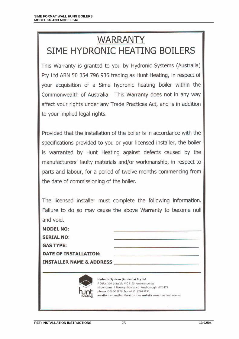
When handing over the operation of the boiler to the user, make sure that he or she is fully aware of the boiler operation, and other ancillary equipment such as room thermostats, timers, thermostatic radiator valves, etc.. Explain the actions to be taken should the boiler fail to operate and where to contact should failure persist. Complete all details of the Warranty and hand to the user, together with the Users Instruction. Also, advise the user of the value of preventative maintenance and cleaning, in order to maintain the optimum performance of the boiler and heating system we recommend servicing of the appliance at regular intervals (i.e. every two years).
BOILER FAILURE
Should the boiler fail to operate correctly when it has been installed and commissioned strictly in accordance with these Instructions, contact Hunt Heating for advice, giving the Model Number, Serial Number, and Gas Type of the boiler.
SIME FORMAT WALL HUNG BOILERS MODEL 34i AND MODEL 34e
40/20/91 SNOITCURTSNI NOITALLATSNI :FER 23

SIME FORMAT WALL HUNG BOILERS MODEL 34i AND MODEL 34e
REF: INSTALLATION INSTRUCTIONS 19/02/04 24
USER’S INSTRUCTIONSUSER’S INSTRUCTIONSUSER’S INSTRUCTIONSUSER’S INSTRUCTIONS
WARNINGS Should a fault occur, turn the boiler OFF, shut any gas valve, and contact the Installer, or Hunt Heating. DO NOT store or place in the immediate vicinity of boiler any flammable liquid or materials. Any serviced or maintenance of the boiler and heating system MUST be carried out by an Authorised Person. DO NOT block any grilles and air openings to the room in which the boiler is installed. LIGHTING AND OPERATION To start the boiler, make sure that the gas valve is OPEN, the electricity supply is turned ON and that the room thermostat is ON. Turn the Selector Knob to the ON position, indicated by a star. A green light should appear indicating that the electric power is ON. The boiler will light automatically and continue to operate until the temperature set by the room thermostat is obtained. It will then modulate to maintain the set temperature. To turn the boiler OFF, turn the Selector Knob to the OFF position. The boiler will now shut down. If the boiler is not to be used for a lengthy period, it is advisable to turn OFF the electricity supply and the gas valve. Should the boiler not operate and a red light appears on the control panel, this indicates that the boiler has failed to ignite correctly. There may also be an orange light, which will either flash or be steady. A steady orange light indicates a faulty boiler thermostat; a flashing orange light indicates insufficient water pressure in the system. Both of them indicate that an Authorised Person must be contacted. If there are no orange lights, turn the Selector Knob to the ignition position, indicated by a flame symbol and hold until both lights flash then release. Should the boiler fail to operate, contact an Authorised Person or the Hunt Heating Service Department.