simmod manual accepted set by jake how simmod … · chapter 1: how simmod works 1.1 simmod is a...
TRANSCRIPT

Simmod Manual
Table of Contents
CHAPTER 1: HOW SIMMOD WORKS................................................................................ 1 1.1 SIMMOD IS A DISCRETE-EVENT SIMULATION ............................................................... 1 1.2 THE EVENT SCHEDULE .................................................................................................... 1 1.3 EXTERNAL EVENTS.......................................................................................................... 2 1.4 THE SIMULATION CLOCK................................................................................................. 2 1.5 SIMMOD NODES AND LINKS: BASIC MODELING COMPONENTS .................................... 3 1.6 STOCHASTIC PROCESSES.................................................................................................. 3
CHAPTER 2: FLIGHTS........................................................................................................... 7 2.1 ARRIVALS ........................................................................................................................ 7 2.2 DEGENERATE AIRPORTS................................................................................................... 8 2.3 DEPARTURES ................................................................................................................... 8 2.4 MULTIPLE, STOCHASTICALLY GENERATED FLIGHTS ....................................................... 9
CHAPTER 3: AIRCRAFT DEFINITION ............................................................................ 11
3.1 AIRCRAFT MODELS........................................................................................................ 11 3.2 AIRCRAFT GROUPS IN AIRSPACE.................................................................................... 11
CHAPTER 4: AIRSPACE STRUCTURE ............................................................................ 13 4.1 ROUTES.......................................................................................................................... 13 4.2 WIND SETS .................................................................................................................... 17 4.3 SECTORS ........................................................................................................................ 17 4.4 PLANS ............................................................................................................................ 18
CHAPTER 5: AIRSPACE LOGIC........................................................................................ 19 5.1 AIRCRAFT MOVEMENT RULES ON THE LINKS ................................................................ 19 5.2 AIRCRAFT MOVEMENT CONTROL AT THE NODES .......................................................... 22 5.3 AIRCRAFT MOVEMENT CONTROL STRATEGIES.............................................................. 25 5.4 LEVEL I: NODE ARRIVAL CONTROL STRATEGIES, CONTINUED ..................................... 32 5.5 LEVEL II: METERING STRATEGY.................................................................................... 37 5.6 LEVEL III: FLOW CONTROL STRATEGY.......................................................................... 39
CHAPTER 6: AIRFIELD....................................................................................................... 43
6.1 RUNWAYS...................................................................................................................... 44 6.2 GATES............................................................................................................................ 46 6.3 LINKS............................................................................................................................. 48 6.4 DEPARTURE QUEUES ..................................................................................................... 51 6.5 AIRCRAFT GROUPS ........................................................................................................ 54 6.6 CONGESTION, HOLDCYCLES, CHECKPOINTS, AND STAGING AREAS FOR ARRIVALS...... 55 6.7 DEPARTURE DE-ICING.................................................................................................... 56 6.8 FLIGHT BANKS............................................................................................................... 57 6.9 METALINKS (NO LONGER USED, SEE DSDPATH)............................................................ 58 6.10 DSDPATHS .................................................................................................................... 58
CHAPTER 7: INTERFACE LOGIC..................................................................................... 59 7.1 PROCEDURES ................................................................................................................. 59
ii
CHAPTER 8: RESETTING SIMULATION PARAMETERS........................................... 69 8.1 FLIGHT CLONING (SETCLONE) ................................................................................... 69 8.2 CHANGING GATE CHARACTERISTICS (SETGATE)........................................................ 69 8.3 INHIBITING INJECTIONS (SETINJ) ................................................................................. 69 8.4 CHANGING LINK CHARACTERISTICS (SETLINK).......................................................... 69 8.5 CHANGING METER POST NODE CHARACTERISTICS (SETMETER) ............................... 69 8.6 CHANGING NODE CHARACTERISTICS (SETNODE) ....................................................... 70 8.7 CHANGING PLANS (SETPLAN)..................................................................................... 70 8.8 INHIBITING PROCEDURES (SETPROC) .......................................................................... 70 8.9 CHANGING ROUTE CHARACTERISTICS (SETROUTE) ................................................... 70 8.10 CHANGING RUNWAY CHARACTERISTICS (SETRWY) ................................................... 70 8.11 CHANGING SECTOR CHARACTERISTICS (SETSECT) ..................................................... 71 8.12 CONTROLLING TOUCH-AND-GO (SETTNG).................................................................. 71 8.13 CHANGING THE WIND CHARACTERISTICS (SETWIND) ................................................ 71 8.14 CHANGING THE WEATHER (SETWX)............................................................................ 71 8.15 SETTING CONDITIONS FOR A FORCED RUNWAY CROSSING (SETXNG)......................... 71
CHAPTER 9: STOCHASTIC PROCESSES........................................................................ 73 9.1 RANDOM LINEAR VARIABLES........................................................................................ 73 9.2 RANDOM NUMBER STREAMS AND SEEDS ...................................................................... 74
CHAPTER 10: SIMULATION OUTPUT........................................................................... 77 10.1 DATA DETAIL REPORTS ................................................................................................. 77 10.2 THE DATA INPUT ECHO REPORT.................................................................................... 77 10.3 THE SIMULATION LOG ................................................................................................... 78 10.4 THE STANDARD REPORT................................................................................................ 78 10.5 THE EXTENDED REPORT ................................................................................................ 78 10.6 PRESENTATION GRAPHICS ............................................................................................. 79 10.7 ANIMATION.................................................................................................................... 79
iii ii

List of Figures
FIGURE 1-1: CUMULATIVE DISTRIBUTION OF GATE OCCUPANCY TIMES FOR COMMUTER AIRCRAFT. ............................................................................................................................... 4
FIGURE 2-1: FLIGHT TYPES............................................................................................................. 7 FIGURE 4-1: DEPENDENT AND INDEPENDENT ROUTES.................................................................. 13 FIGURE 4-2: SAMPLE ROUTES: CROSSING, MERGING AND DIVERGING ........................................ 14 FIGURE 4-3: SECTORS ................................................................................................................... 18 FIGURE 5-1: LINK VECTORING OR PATH STRETCHING.................................................................. 20 FIGURE 5-2: PASSING AND THE NODE ARRIVAL QUEUE ............................................................... 21 FIGURE 5-3: LIGHT/HEAVY SEQUENCING ..................................................................................... 22 FIGURE 5-4: HOLDING STRATEGY 1.............................................................................................. 24 FIGURE 5-5: HOLDING STRATEGY 2.............................................................................................. 24 FIGURE 5-6: HOLDING STRATEGY 3.............................................................................................. 25 FIGURE 5-7: QFIFO LOGIC WITH NO DELAY................................................................................ 27 FIGURE 5-8: QFIFO LOGIC WITH SPEED DELAY........................................................................... 27 FIGURE 5-9: QFIFO LOGIC WITH VECTORING DELAY.................................................................. 28 FIGURE 5-10: QFIFO LOGIC WITH HOLDING DELAY.................................................................... 28 FIGURE 5-11: SPEEDFIT AT NOMINAL POSITION WITH SPEED INCREASE ...................................... 30 FIGURE 5-12: SPEEDFIT AT FORWARD POSITION WITH SPEED INCREASE...................................... 30 FIGURE 5-13: SPEEDFIT AT NOMINAL POSITION WITH SPEED DECREASE ..................................... 31 FIGURE 5-14: SPEEDFIT AT BACKWARD POSITION WITH SPEED DECREASE, VECTORING, AND
HOLDING DELAY ................................................................................................................... 31 FIGURE 5-15: MULTIFIT AT NOMINAL POSITION WITH SPEED INCREASE OF PRECEDING AIRCRAFT
............................................................................................................................................... 34 FIGURE 5-16: MULTIFIT AT NOMINAL POSITION WITH SPEED DECREASE OF SUCCEEDING
AIRCRAFT .............................................................................................................................. 34 FIGURE 5-17: MULTIFIT AT BACK POSITION, SPEED DECREASE OF SUCCEEDING AIRCRAFT ....... 36 FIGURE 5-18: METERED AIRSPACE ............................................................................................... 38 FIGURE 5-19: FLOW CONTROLLED AIRSPACE............................................................................... 40 FIGURE 6-1: AIRFIELD NETWORK ................................................................................................. 43 FIGURE 6-2: RUNWAY AND TAXIPATH INTERACTION ................................................................... 44 FIGURE 6-3: RUNWAY CROSSING LOGIC USING THE RC_FUDGE_TIME GLOBAL VARIABLE.... 46 FIGURE 6-4: GATE GROUPS .......................................................................................................... 47 FIGURE 6-5: TAXIPATH COSTS AND LINK CHARACTERISTICS ....................................................... 50 FIGURE 6-6: TAXIPATH COSTS AND LINK CHARACTERISTICS ....................................................... 51 FIGURE 6-7: ALTERNATE RUNWAY DEPARTURES WITH FRAGMENTARY ROUTE SECTIONS .......... 52 FIGURE 6-8: DEPARTURE QUEUE CAPACITY................................................................................. 53 FIGURE 6-9: RUNWAY ROLL TIMES .............................................................................................. 54 FIGURE 6-10: BANK LOGIC........................................................................................................... 57 FIGURE 7-1: DEPARTURE CONTROL.............................................................................................. 60 FIGURE 7-2: TAKEOFF/LANDING CONTROLS ................................................................................ 61 FIGURE 7-3: NON-PAIRED ARRIVALS ........................................................................................... 62 FIGURE 7-4: PAIR CONTROL, PAIRED ARRIVALS .......................................................................... 63 FIGURE 7-5: STAGGER CONTROL .................................................................................................. 65 FIGURE 7-6: TERMINAL REROUTING AIRSPACE ............................................................................ 66 FIGURE 9-1: CUMULATIVE RANDOM LINEAR VARIABLES ............................................................ 74
iv

Chapter 1: How SIMMOD Works 1.1 SIMMOD is a Discrete-Event Simulation SIMMOD is a discrete-event simulation model: it represents a system evolving over time by means of a mathematical model, the state of which changes at discrete points in time. These points are those at which an event occurs, where an event is an instantaneous occurrence that changes the state variables.
Consider a simple runway departure queue. An airplane joining this queue is an event. SIMMOD calculates the effect of this new event on the existing system and modifies or adds state variables resulting from this event before considering the next event.
Suppose you wish to estimate the average delay of planes in this basic runway queue. The state variables for the simplest possible model would include the following:
• The status of the runway (occupied or empty) • The number of planes in the departure queue for this runway (if any) • The time at which each plane enters the departure queue
The status of the runway is needed to determine whether an aircraft can advance to the runway immediately when it reaches the front of the queue.
Assume that when a plane departs from the runway, the runway is available for the next departure. When a plane departs, SIMMOD checks the departure queue. If there are no aircraft waiting in the queue, the runway remains empty; otherwise, the first aircraft waiting in the queue occupies the runway and departs.
The time at which each aircraft enters the queue is used to compute its delay in the queue, the difference between the time it enters and the time it leaves the queue for departure.
There are two different events in this example: (1) entering the queue and (2) leaving the runway. Entering the queue is an event because it causes the runway status (a state variable) to change from empty to occupied or it increases the number of aircraft in the queue (another state variable) by one. Correspondingly, leaving the runway is an event because it causes the runway status to change from occupied to empty or decreases the number in the queue by one.
1.2 The Event Schedule The event schedule and the simulation clock work together to process SIMMOD events in the proper sequence. SIMMOD is sometimes called an "event stepped" simulation, because it steps forward from one event to the next. With each step, the model bypasses an interval in which no events occur. It processes each event strictly according to the order of its appearance in the event schedule.
If two events are scheduled to occur at the same time, SIMMOD prioritizes them and processes them in sequence, without moving the simulation clock forward. The priority can be tracked by examining the Simulation Log, which lists every event in chronological order. Table 1-1 shows a simple event schedule.
1
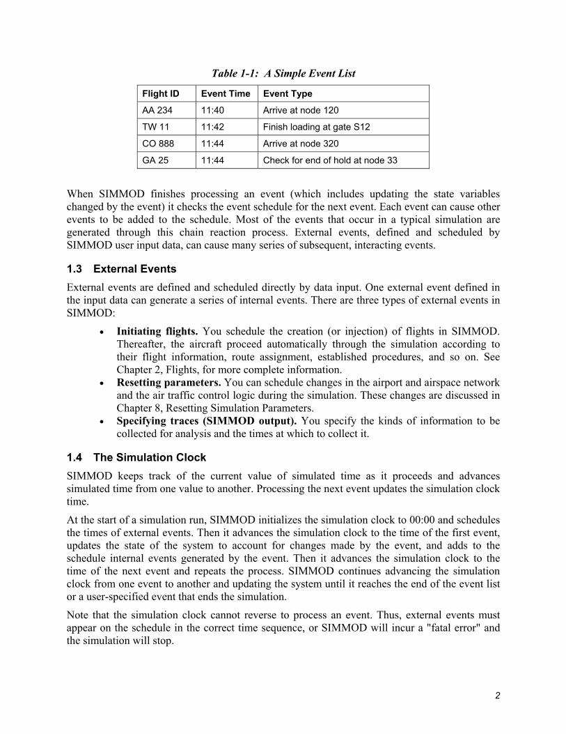
Table 1-1: A Simple Event List
Flight ID Event Time Event Type
AA 234 11:40 Arrive at node 120
TW 11 11:42 Finish loading at gate S12
CO 888 11:44 Arrive at node 320
GA 25 11:44 Check for end of hold at node 33
When SIMMOD finishes processing an event (which includes updating the state variables changed by the event) it checks the event schedule for the next event. Each event can cause other events to be added to the schedule. Most of the events that occur in a typical simulation are generated through this chain reaction process. External events, defined and scheduled by SIMMOD user input data, can cause many series of subsequent, interacting events.
1.3 External Events External events are defined and scheduled directly by data input. One external event defined in the input data can generate a series of internal events. There are three types of external events in SIMMOD:
• Initiating flights. You schedule the creation (or injection) of flights in SIMMOD. Thereafter, the aircraft proceed automatically through the simulation according to their flight information, route assignment, established procedures, and so on. See Chapter 2, Flights, for more complete information.
• Resetting parameters. You can schedule changes in the airport and airspace network and the air traffic control logic during the simulation. These changes are discussed in Chapter 8, Resetting Simulation Parameters.
• Specifying traces (SIMMOD output). You specify the kinds of information to be collected for analysis and the times at which to collect it.
1.4 The Simulation Clock SIMMOD keeps track of the current value of simulated time as it proceeds and advances simulated time from one value to another. Processing the next event updates the simulation clock time.
At the start of a simulation run, SIMMOD initializes the simulation clock to 00:00 and schedules the times of external events. Then it advances the simulation clock to the time of the first event, updates the state of the system to account for changes made by the event, and adds to the schedule internal events generated by the event. Then it advances the simulation clock to the time of the next event and repeats the process. SIMMOD continues advancing the simulation clock from one event to another and updating the system until it reaches the end of the event list or a user-specified event that ends the simulation.
Note that the simulation clock cannot reverse to process an event. Thus, external events must appear on the schedule in the correct time sequence, or SIMMOD will incur a "fatal error" and the simulation will stop.
2
1.5 SIMMOD Nodes and Links: Basic Modeling Components SIMMOD represents an airport or airspace system as a series of nodes connected by links. A node is a point in a coordinate system where SIMMOD evaluates an aircraft’s position with respect to other aircraft in the system. A link defines the path between two nodes. Aircraft move from one node to another only along a defined link.
SIMMOD maintains ground (airfield) nodes and airspace nodes as separate groups. Ground nodes describe airfield locations such as gates, departure queues, or runway and taxipath intersections. Airspace nodes describe airspace locations such as navigational fixes, holding queues, merge points for routes, or interfaces with an airport.
SIMMOD also maintains ground and airspace links separately. Ground links can represent taxipaths and runways. Airspace links can represent routes. Larger structures (e.g., runways and routes) are usually composed of several links.
Nodes and links in the airspace and on the airfield have slightly different characteristics, which are discussed at length in Chapter 5, Airspace Logic, and Chapter 6, Airfield Logic.
Note: For more information on discrete-event simulation and simulation modeling in SIMSCRIPT II.5®, see Building Simulation Models with SIMSCRIPT II.5 by Edward C. Russell (CACI Inc.-Fed., 1983); SIMSCRIPT II.5 Reference Handbook, 3rd Edition (CACI Inc.-Fed, 1989); or Simulation Modeling and Analysis by Averill M. Law and W. David Kelton (McGraw-Hill, 1982).
1.6 Stochastic Processes SIMMOD is a stochastic model. It uses random variables to produce unique output representing day-to-day variations in air traffic phenomena. Because SIMMOD is designed to produce realistic results from any iteration of a defined application data set, it is usually necessary to run several iterations with a single data set in order to establish statistically significant tendencies. For a run of several consecutive iterations, the Report program produces aggregate values and, where appropriate, averages and standard deviations. For example, where frequencies indicating the usage of a given facility are reported for a single-iteration run, average frequencies are reported for a multiple-iteration run.
1.6.1 Random Linear Variables SIMMOD uses random linear variables to simulate certain airport and airspace phenomena. You can provide variation in your model by defining distribution values for the following variables:
• Gate-occupancy times (for loading or unloading passengers) • Injection time of multiple arrivals and departures • The cloning of arrivals and departures • Takeoff and landing roll distances • Intrail separation multiplier (to vary the defined separation requirements) • Lateness of flights • The probability of holding flights to accommodate late arrivals in hubbing operations • The transfer time (time for unloading and loading passengers) between flights in
hubbing operations • Push-back/power-back times • Runway crossing start-up times
3

• Slot window times
User-defined cumulative probability distributions determine the amount of variation. SIMMOD generates a random real number between 0 and 1, and uses this number to select values from the distribution.
Cumulative probability distributions are defined by pairs of numbers. The first number in the pair represents the probability of a value less than or equal to x occurring; the second defines the corresponding value x. Two such pairs, one indicating 0% probability for the lower value in the distribution range and the other 100% probability for the upper value, defines a basic linear
Figure 1-1: Cumulative Distribution of Gate Occupancy T
function. Additional pairs specify a more detailed distribution.
imes for Commuter Aircraft. Fig te-
very run of an application data set, it creates
er in a random number stream is called the seed. The random number generator uses this seed to produce the ensuing stream. Starting with the same seed, the random number
0
5
10
15
20
25
30
35
40
0 0.1 0.2 0.3 0.4 0.5 0.6 0.7 0.8 0.9 1Probability P(x)
Gat
e-O
ccup
ancy
Tim
es, i
n M
inut
es
(.18, 22)
(0.00, 8)
(.62, 25)
(1.00, 36)
ure 1-1 shows a cumulative distribution that defines the range and probabilities for gaoccupancy times for commuter aircraft. This distribution has four number pairs: (0.0, 8); (0.18, 22); (0.62, 25); and (1.0, 36). The lowest value that can be returned is 8 minutes; the highest is 36 minutes. There is an 18% probability that the gate time will be 22 minutes or less, and a 62% probability that it will be 25 minutes or less. Note that a percentage is entered as a number between 0.0 and 1.0; 100% is entered as 1.0. In this example, 62% was entered as 0.62.
1.6.2 Random Number Streams and Seeds Because SIMMOD uses many random numbers in ea sequence, or stream, of random numbers for each iteration. These streams are created by a random number generator built into SIMSCRIPT II.5, the language in which SIMMOD is programmed.
The first numb
4

generator will always produce exactly the same random number stream (assuming that the simulation is run on a machine with the same processor). This is significant because it allows you to reproduce the simulation results achieved with a given data set. See Chapter 9, Stochastic Processes, for a further discussion of randomness in SIMMOD.
5

This page intentionally left blank.
6

Chapter 2: Flights In SIMMOD, a flight is an aircraft with a unique identifier (ID) and a set of data, including its:
• Type of flight • Starting time • Airspace route.
Depending on the scenario being simulated, the user can define other data to restrict the flight’s path and limit its range of options during the simulation.
Figure 2-1: Flight Types
As shown in Figure 2-1, there are three types of flights:
• Arrivals at an airport • Departures from an airport • Flights passing through the airspace that do not land (overflights).
2.1 Arrivals A SIMMOD arrival flight always starts in the airspace. The basic arrival consists of a flight that:
• Traverses an airspace route
7
• Lands on a runway • Taxis to a gate • Unloads passengers (i.e., occupies a gate) • Exits the simulation.
2.1.1 Turnaround An arrival flight can also turn around at an airport and depart. This means an arrival and departure are dependent on each other. If the arrival is late, the dependent departure must await the arrival before it can load passengers and depart. The arrival with a turnaround departure consists of a flight that:
• Traverses an airspace route • Lands on a runway • Taxis to a gate • Unloads passengers • Loads passengers • Taxis to a runway • Takes-off on a runway • Traverses an airspace route • Exits the simulation.
2.1.2 Overflights An overflight is an arrival that does not land at an airport. The end of the arrival route is not an airport, so the flight begins and ends in airspace. After traversing its airspace route, the overflight exits the simulation.
2.2 Degenerate airports When the simulation does not include an airfield in its scenario, arrivals use a “degenerate airport.” The physical attributes of such an airport, other than its location at the end of an airspace route, are not modeled. The arrival at a degenerate airport consists of a flight that traverses an airspace route and exits the simulation.
No ground simulation occurs at degenerate airports. If the SIMMOD analysis project concerns only the airspace, this frees the user from generating airfield data. The degenerate airport also offers greater flexibility, as arriving flights are not subject to restrictive airport landing procedures.
All arrivals in the simulation must be created in the airspace, so the simulation must include a minimally defined airspace structure even when the ground simulation is of primary concern. To simplify the airspace definition, it is possible to define the required airspace route as a single link. This link will represent the final approach path for arrivals and will allow the runway management to be accurately modeled.
2.3 Departures A SIMMOD departure flight always starts at an airport. The basic departure (which is called an "emplane" for the purposes of simulation) consists of a flight that is created at a gate and:
• Loads passengers • Taxis to a runway
8

• Takes off on a runway • Traverses the airspace route • Exits the simulation.
A departure can be defined by input data to generate an arrival at another airport. When a departure reaches the end of its departure route, the simulation will create a dependent arrival on a route leading to that airport. The departure with a dependent arrival consists of a flight that is created at a gate and:
• Loads passengers • Taxis to a runway • Takes off on a runway • Traverses the airspace departure route • Becomes a dependent arrival • Traverses an airspace arrival route • Lands on a runway • Taxis to a gate • Unloads passengers • Exits the simulation.
When the airfield is not included in the modeled scenario, the departures are created at a degenerate airport. The physical attributes of such an airport, other than its location at the end of an airspace route, are not modeled. A departure at a degenerate airport consists of a flight traversing an airspace route and either exiting the simulation or creating a dependent arrival.
No ground simulation occurs at degenerate airports.
All departures must enter the airspace before exiting the simulation, so a ground simulation must have at least a minimally defined airspace structure. To simplify the airspace definition, it is possible to define each route as a single link. This link will represent the initial airspace path for departures and allow the runway management to be accurately modeled.
2.4 Multiple, Stochastically Generated Flights The flights described above are either created individually by the user, as external events, or as dependent arrivals and departures.
If individual flight information is not available or not required, the simulation can create flights using its multiple arrival (MULTARR) and multiple departure (MULTDEP) features. These allow the simulation to create a number of flights stochastically (i.e., randomly) over a given time period. The number of flights and the time period are defined by input data.
Stochastically generated aircraft can represent additional flights needed to model congestion in the modeled airport or airspace, e.g., general aviation (GA) flights or flights from other airlines. These aircraft can also represent projected scheduling where real numbers do not exist.
2.4.1 Cloning Cloning selectively increases or decreases traffic on specific routes, and provides a convenient means of modifying the existing schedule while still reflecting the traffic pattern defined by the
9

user's input data. Cloning is especially helpful in estimating traffic congestion based on a projected increase or decrease in scheduling.
Cloning replicates or removes individually defined arriving and departing flights. Stochastically generated flights, described above, may not be cloned.
Cloning can be set to take effect for any time interval on any route. For example, one may need to simulate the effects of a 20% increase in traffic on one route and a 10% decrease on another during peak morning hours. Cloning is an appropriate approach to this problem because there is no empirical data to represent the change, yet the analysis requires modeling of a specific increases and decreases in traffic on defined airspace routes during a given period of time.
The process of cloning involves a random draw, which applies a realistic uncertainty to the duplication of existing flights.
When initializing a flight, SIMMOD checks whether cloning is in effect. If cloning is in effect, the cloning probability is checked for the flight. This probability will range from -100 to 500 percent. If the probability is negative, the flight may be removed from the simulation.
If the cloning probability value is greater than 100, the flight will be cloned once for each 100 percent of probability defined. The number of clones may then be increased by one, based on the difference between the total percentage of probability and the same percentage rounded to the next lowest 100.
The simulation makes the decision to create this extra clone (increasing the number by one) by drawing a random number between 0 and 100. This number is then compared to the probability difference mentioned above. If the random number is less than the probability difference, the flight is cloned. If it is greater, no extra clone is created.
Thus, if the cloning probability for a flight is defined as 267 percent, the flight will be cloned at least twice because the probability exceeds 200 percent. If the random number drawn is less than 67, the flight will be cloned a total of three times.
The following chart shows the options based on the range of cloning probability values:
Table 2-1: Cloning Flights
Probability Number of aircraft cloned
-100% to 0% -1 or 0
0% to 100% 0 or 1
100% to 200% 1 or 2
200% to 300% 2 or 3
300% to 400% 3 or 4
400% to 500% 4 or 5
A cloned flight's injection time is based on the lateness distribution specified for the original flight. Thus, if three clone flights are generated, they will be injected into the simulation at different times.
10

Chapter 3: Aircraft Definition Every flight created by the simulation is identified as a certain aircraft model. This and other aircraft data allows the simulation to distinguish among different aircraft and to assign them the appropriate separation rules, sequencing, speeds, takeoff and landing characteristics, and limitations based on size.
The simulation references an aircraft in three ways: model number, airspace group number, and airfield group number. Each reference is discussed below.
3.1 Aircraft Models SIMMOD uses an aircraft index number to identify the aircraft model of each flight. The numbers refer to aircraft model definitions in the Integrated Noise Model (INM) Data Base No. 9, a copy of which is supplied with SIMMOD. (The INM is an FAA model that determines aircraft noise impact at and around airports.) For example, the aircraft number 01 refers to the first aircraft described in the INM list, a B747-100/JT9DBD.
If the INM database is deemed unacceptable for a specific user's application, the simulation will accept a different file with the same format.
The aircraft number is also used to define gate blockage. For each gate in the application, the analyst can define which adjacent gates will become blocked (unavailable for use) when the gate is occupied by an aircraft of any given number (see Gate blocking in Chapter 6, Airfield).
The aircraft model descriptions in the INM database include takeoff weights for trips of various lengths. As shown in the chart below, the maximum INM aircraft weights generally indicate the size category of the individual aircraft models. Thus, aircraft may be assigned to size groups according to their weight category, as in the following table.
Table 3-1: Aircraft size groups
INM max. weight Aircraft Group Group Number
< 10,000 lb. Single engine / GA 1
10,000 lb. to 100,000 lb. Twin engine / Small 2
100,000 lb. to 300,000 lb. Commercial jet / Large 3
> 300,000 lb. Wide body and jumbo jets / Heavy 4
3.2 Aircraft Groups in Airspace Many different models of aircraft have roughly equivalent characteristics when airborne. For the purposes of simulating airspace operations, aircraft are therefore classified into groups. SIMMOD does not restrict the number or definition of aircraft groups defined for the airspace portion of the model, nor does it require that these groups match the aircraft groups defined for the airfield.
Aircraft in the airspace model are typically classified into five basic types: Large/heavy, Heavy, Large, Small, and GA (for General Aviation). The aircraft models belonging to each group must be listed in the data input so the simulation can determine the aircraft group to which each flight belongs and appropriately model the flight's airspace characteristics.
11
Characteristics defined for each group include:
• Speed ranges by link type (defined in Links and Link Types in Chapter 4, Airspace Structure
• Holding queue by node type (defined in Nodes and Node Types in Chapter 4, Airspace Structure
• Minimum separation list for this group (see below) • Intrail separation multiplier • Wake turbulence sequencing.
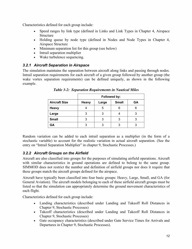
3.2.1 Aircraft Separation in Airspace The simulation maintains the separation between aircraft along links and passing through nodes. Intrail separation requirements for each aircraft of a given group followed by another group (the wake vortex separation requirements) can be defined uniquely, as shown in the following example.
Table 3-2: Separation Requirements in Nautical Miles
Followed by:
Aircraft Size Heavy Large Small GA
Heavy 4 5 6 6
Large 3 3 4 3
Small 3 3 3 3
GA 3 3 3 3
Random variation can be added to each intrail separation as a multiplier (in the form of a stochastic variable) to account for the realistic variation in actual aircraft separation. (See the entry on “Intrail Separation Multiplier” in chapter 9, Stochastic Processes.)
3.2.2 Aircraft Groups on the Airfield Aircraft are also classified into groups for the purposes of simulating airfield operations. Aircraft with similar characteristics in ground operations are defined to belong to the same group. SIMMOD does not restrict the number and definition of airfield groups nor does it require that these groups match the aircraft groups defined for the airspace.
Aircraft have typically been classified into four basic groups: Heavy, Large, Small, and GA (for General Aviation). The aircraft models belonging to each of these airfield aircraft groups must be listed so that the simulation can appropriately determine the ground movement characteristics of each flight.
Characteristics defined for each group include:
• Landing characteristics (described under Landing and Takeoff Roll Distances in Chapter 9, Stochastic Processes)
• Takeoff characteristics (described under Landing and Takeoff Roll Distances in Chapter 9, Stochastic Processes)
• Gate occupancy characteristics (described under Gate Service Times for Arrivals and Departures in Chapter 9, Stochastic Processes).
12

Chapter 4: Airspace Structure SIMMOD airspace is composed of an interrelated network of aircraft routes. These routes are defined by the analyst as a series of nodes and links. When two or more routes converge, some nodes and links will be held in common; that is to say, they will appear in the definition of more than one route.
All aircraft move in the airspace along these routes, and every flight entering the simulation must be assigned to a route in the input data. As an aircraft moves through the airspace, separation requirements are checked between it and other aircraft on the same path, merging paths, and crossing paths.
Unlike actual flights, aircraft in the simulation cannot deviate from their designated paths. This being the case, vertical and lateral separations are not checked by the simulation. These separation requirements are maintained insofar as routes are correctly defined by the user with vertical and lateral separation.
Each node on a path is given an altitude by definition; the simulation uses the altitude to calculate fuel consumption and speeds not given as true airspeed. Altitude is not checked or adjusted by the simulation to resolve conflicts.
Two links can occupy the same ground coordinates in the simulation but only at different altitudes. SIMMOD can handle these either as two independent paths that never affect each other or as two dependent paths that have all or part of a path in common. The decision to make paths dependent or independent is accomplished in the definition of the input data. See Figure 4-1, Dependent and Independent Routes.
Figure 4-1: Dependent and Independent Routes
It is possible to make some changes in the structure of the airspace during the simulation. This is further explained in Chapter 8, Resetting Simulation Parameters.
4.1 Routes A route is defined as a series of nodes connected by links listed sequentially in the direction of travel. A flight must be assigned to a route in the data input.
13
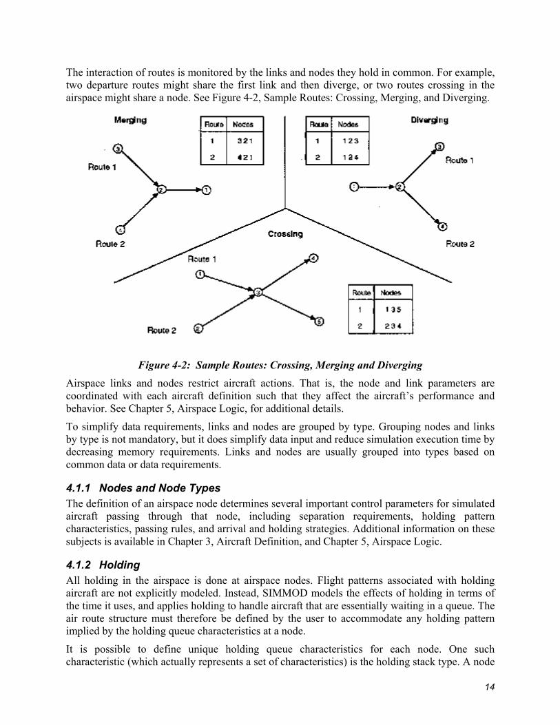
The interaction of routes is monitored by the links and nodes they hold in common. For example, two departure routes might share the first link and then diverge, or two routes crossing in the airspace might share a node. See Figure 4-2, Sample Routes: Crossing, Merging, and Diverging.
Figure 4-2: Sample Routes: Crossing, Merging and Diverging
Airspace links and nodes restrict aircraft actions. That is, the node and link parameters are coordinated with each aircraft definition such that they affect the aircraft’s performance and behavior. See Chapter 5, Airspace Logic, for additional details.
To simplify data requirements, links and nodes are grouped by type. Grouping nodes and links by type is not mandatory, but it does simplify data input and reduce simulation execution time by decreasing memory requirements. Links and nodes are usually grouped into types based on common data or data requirements.
4.1.1 Nodes and Node Types The definition of an airspace node determines several important control parameters for simulated aircraft passing through that node, including separation requirements, holding pattern characteristics, passing rules, and arrival and holding strategies. Additional information on these subjects is available in Chapter 3, Aircraft Definition, and Chapter 5, Airspace Logic.
4.1.2 Holding All holding in the airspace is done at airspace nodes. Flight patterns associated with holding aircraft are not explicitly modeled. Instead, SIMMOD models the effects of holding in terms of the time it uses, and applies holding to handle aircraft that are essentially waiting in a queue. The air route structure must therefore be defined by the user to accommodate any holding pattern implied by the holding queue characteristics at a node.
It is possible to define unique holding queue characteristics for each node. One such characteristic (which actually represents a set of characteristics) is the holding stack type. A node
14

defined with a holding stack type allows each aircraft in the simulation to hold in a unique and appropriate manner.
Several sets of holding stack data, each representing a different stack type, can be defined for each aircraft group. During the simulation, each node defined with a holding stack type can thereby reference the corresponding holding stack data set for each aircraft.
For example, if a node is defined to use a holding stack of type 3, then each aircraft holding at that node uses the type 3 holding stack data for its group.
The definition of an airspace node must indicate which holding stack type it will employ, if any. The decision to use a certain holding stack type should be based on the node’s position and function in the airspace model.
To simplify data input, it is convenient to group airspace nodes with the same holding queue characteristics as the same type of node.
If the definition of a node does not specify a particular type of holding stack, holding aircraft simply remain at the node until released — first in, first out — to proceed to the next node. There is no minimum hold period in this case.
4.1.3 Holding Stack Characteristics. Holding stack characteristics define the time restrictions imposed upon an aircraft waiting to leave a hold pattern at a node. The restrictions define two values: (1) the minimum holding time and (2) the holding pattern exit time interval. The latter time increment determines the intervals at which aircraft can exit the pattern.
For example, an aircraft at a node may be required to hold at least 5 minutes. It may exit at that time (five minutes) or at two-minute intervals thereafter, i.e., at seven, nine, eleven, etc. minutes.
The holding stack type also determines the speed of the aircraft as it holds in a stack.
For additional information, see the entry on Airspace Holding in Chapter 5, Airspace Logic.
4.1.4 Interface Nodes Some nodes in the airspace are defined as interface nodes. Interface nodes indicate the transition between the ground and air simulation. They are typically near the end of a runway. If a node in an airspace arrival route is an interface node, the simulation will continue to handle the flight in the airport model or in a degenerate airport.
The first node of an airspace departure route is an interface node. After takeoff, the simulation continues a flight from that node. A complete description of the logic of interface nodes is provided in Chapter 7, Interface Logic.
4.1.5 Links and Link Types Aircraft move from one node to the next only along a defined link. Airspace links typically represent segments of a flight path. Routes are usually comprised of several links.
Links can be grouped by location to simulate airspace sectors. SIMMOD can monitor these sectors for occupancy and control them based on sector capacity.
To represent a set of path segments affected by the same winds, links can also be grouped (e.g., by altitude) into Wind Sets.
15
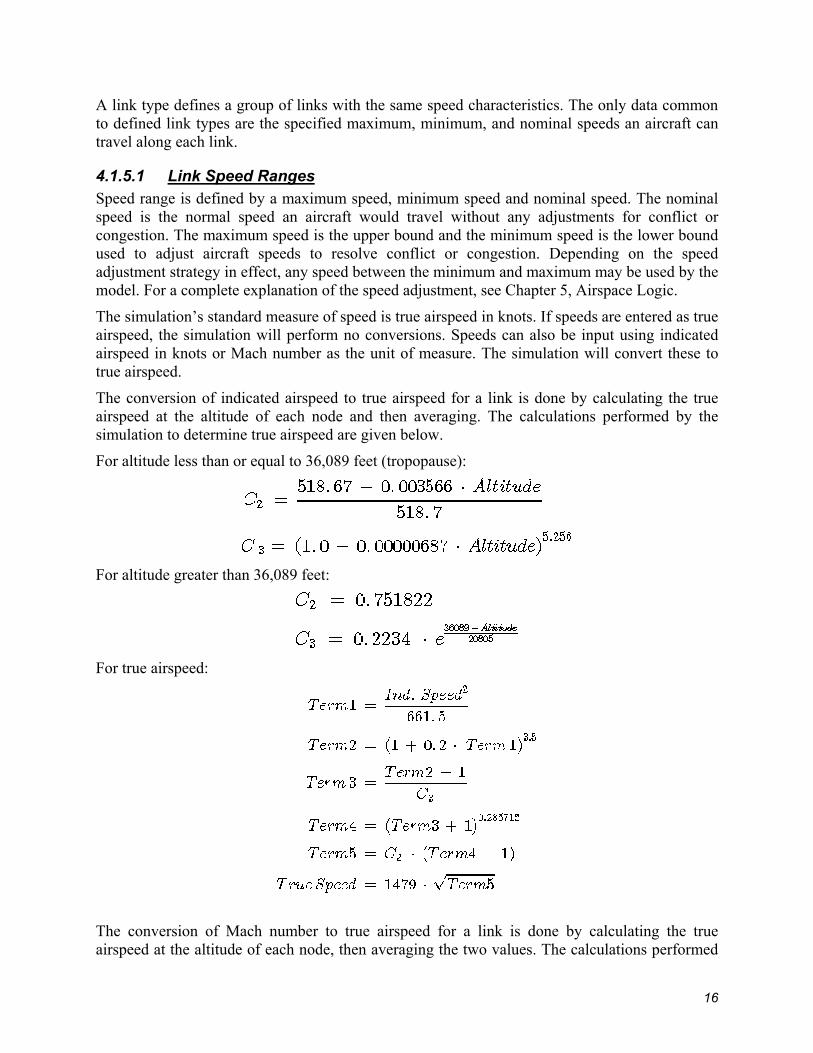
A link type defines a group of links with the same speed characteristics. The only data common to defined link types are the specified maximum, minimum, and nominal speeds an aircraft can travel along each link.
4.1.5.1 Link Speed Ranges Speed range is defined by a maximum speed, minimum speed and nominal speed. The nominal speed is the normal speed an aircraft would travel without any adjustments for conflict or congestion. The maximum speed is the upper bound and the minimum speed is the lower bound used to adjust aircraft speeds to resolve conflict or congestion. Depending on the speed adjustment strategy in effect, any speed between the minimum and maximum may be used by the model. For a complete explanation of the speed adjustment, see Chapter 5, Airspace Logic.
The simulation’s standard measure of speed is true airspeed in knots. If speeds are entered as true airspeed, the simulation will perform no conversions. Speeds can also be input using indicated airspeed in knots or Mach number as the unit of measure. The simulation will convert these to true airspeed.
The conversion of indicated airspeed to true airspeed for a link is done by calculating the true airspeed at the altitude of each node and then averaging. The calculations performed by the simulation to determine true airspeed are given below.
For altitude less than or equal to 36,089 feet (tropopause):
For altitude greater than 36,089 feet:
For true airspeed:
The conversion of Mach number to true airspeed for a link is done by calculating the true airspeed at the altitude of each node, then averaging the two values. The calculations performed
16

by the simulation to determine true airspeed are given below. The speed of sound is a function of temperature and pressure, which vary with ephemeral atmospheric conditions. SIMMOD assumes 59 deg. F at sea level as standard.
For altitude less than or equal to 36,089 feet:
For altitude greater than 36,089 feet:
For True airspeed:
4.2 Wind Sets The effects of wind can vary by link. Links can be grouped together such that they have the same wind effects. These groups are called wind sets. Wind sets are defined by data input.
Typical examples of wind sets include:
• High vs. low altitude links • Groups linked by physical location • Terminal approach vs. en route links.
If no windsets are defined by data input, all links are grouped into one windset. If some windsets are defined, the links not included in a windset are grouped together in a windset appearing at the end of the wind set list.
The simulation will consider the effects of wind in all speed calculations, including those which yield travel time and fuel consumption figures. The wind data includes speed in knots and direction.
4.3 Sectors The simulation can measure the combined capacity of a group of links defined as a sector. The sector capacity includes the total number of aircraft (a) on links included in the sector or (b) holding at nodes included within the sector or (c) holding at nodes at the defined perimeter of the sector if the aircraft is exiting from the sector. If an aircraft is entering the sector and holding at a node at the defined perimeter of the sector, then it is still considered to be in the previous sector. Holding will occur at the nodes on the edge of a sector if it is full. See Figure 4-3, Sectors.
17

Figure 4-3: Sectors
Airspace sectors can be explicitly defined by data input. If no sectors are defined, all links are grouped into one sector. If some sectors are defined, the links not included in a sector are grouped together in a sector at the end of the sector list.
4.4 Plans The definition of routes is more complex than a simple node and link list. A group of routes can be defined to handle different operations for an airport.
An airport might be operating with a southern flow and then, because of changing conditions or operational requirements, change to a northern flow. The simulation considers each type of operation a plan. Under a plan certain routes are available for use. If a plan changes, a different set of routes will become available.
If no plan information is defined by input the simulation considers all routes available in plan 1. For an explanation of the simulation logic involved in plan changes see Chapter 8, Resetting Simulation Parameters.
18
Chapter 5: Airspace Logic SIMMOD's airspace model logic manages the simultaneous movement of aircraft on all airspace routes. As noted earlier in this manual, routes are defined as a series of nodes connected by links. Airspace movement takes place along these links. As each aircraft traverses a link, it is required to maintain minimum separation from preceding and succeeding aircraft unless the link is defined to allow passing. Other considerations that restrict aircraft progress on a route include the capacity of a link or a sector, projections of downstream congestion, and aircraft movement controls on the links.
The simulation evaluates each aircraft's position with respect to other aircraft in the system while the aircraft is at a node. Based on data input, SIMMOD resolves air traffic control decisions (e.g., whether to allow another aircraft on a link, what intrail separation the aircraft will maintain) before each aircraft is allowed to enter the link. This chapter first considers some fundamental rules for aircraft movement on airspace links. It then addresses aircraft control at airspace nodes (holding and holding strategies), and three aircraft movement control strategy levels and their ramifications.
5.1 Aircraft Movement Rules on the Links Links may be defined to model certain circumstances, opportunities, and limitations that an aircraft would encounter in airspace. The definition of a link may change the effects of an aircraft's control strategy.
5.1.1 Link Types and Aircraft Speeds A link type defines a group of links with the same aircraft speed ranges. For the purposes of simulation, SIMMOD must determine the length of time each aircraft will use to traverse each link. This length of time is used to assign the flight a time of arrival (TOA) at the next node. The length of time is determined using three speed parameters: maximum speed, minimum speed, and nominal speed. These speeds are defined for each model of aircraft traveling on each type of link. The preferred speed is the nominal speed. The aircraft will always use the nominal speed if it is possible to do so. If it is not, the aircraft will use a speed between the maximum and the nominal, or between the nominal and the minimum, depending on the aircraft movement control strategy in effect.
5.1.2 Link Time for Vectoring or Path Stretching An aircraft may have to use up more time traversing a link than it can by merely traveling at the minimum speed. SIMMOD therefore allows the user to define for each link an amount of time that may be used in vectoring or path stretching. SIMMOD makes no distinction between vectoring and path stretching. The simulation decides to delay the flight based on time requirements. In effect, SIMMOD adds to the link distance by adding an appropriate amount of vectoring time. This extra time represents the vector distance added to the link traveled at the minimum speed. Since the vectoring time is defined by link and not by aircraft type, vectoring time should approximate a realistic delay for all aircraft types flying a link. See Figure 5-1, Link Vectoring or Path Stretching.
19

Figure 5-1: Link Vectoring or Path Stretching
5.1.3 Wind The effect of wind in airspace is considered in the calculation of an aircraft's TOA at a node. Every speed calculation is adjusted for wind effects. The wind calculation is:
Setting the wind for the simulation is further explained in the Wind Sets entry of the previous chapter, and in Chapter 8, Resetting Simulation Parameters, under the entry Changing the Wind Characteristics.
5.1.4 Passing and Wake Turbulence Along a Link The link overtake setting allows aircraft to pass one another along a link. If passing is allowed on a link, an aircraft's position in the arrival queue sequence at the next node is not restricted by the TOA's of aircraft preceding it on the link. See Figure 5-2, Passing and the Node Arrival Queue.
20

Figure 5-2: Passing and the Node Arrival Queue
The feasibility of any aircraft position in the next node's arrival queue is determined by the node's arrival control strategy and the aircraft's performance characteristics. For example, if the next node applies a strict First-In-First-Out arrival queue strategy (SIMMOD's "QFIFO" strategy) to aircraft arriving from a link, an aircraft traveling on that link will not be able to change its position in the node arrival queue, even though it technically has the ability to pass.
On the other hand, if passing is not allowed on a link, and if there are no other links leading to the next node, then the only position available to an aircraft entering the node arrival queue is behind the preceding aircraft on the same link, i.e., in QFIFO order.
In such circumstances, aircraft must therefore be allowed to pass in order to exploit the SIMMOD aircraft movement strategies beyond QFIFO. These strategies will be explained in full detail further below.
When aircraft are allowed to pass on a link, the simulation does not enforce the intrail separation requirements that would otherwise protect light aircraft from wake turbulence. However, the user can prevent a light aircraft from directly following a heavy aircraft on the same link by setting the wake turbulence flag. This light/heavy sequencing protocol essentially restricts the positions available to an aircraft entering the next node's arrival queue. See Figure 5-3, Light/Heavy sequencing.
21

Figure 5-3: Light/Heavy Sequencing
A light aircraft in the final position in the queue constitutes an exception to this protocol, because it must always be possible for an aircraft to be last in the queue.
The wake turbulence flag inhibits the option of vectoring on a link where wake turbulence (light/heavy sequencing) is in effect. Since the model does not precisely track the paths aircraft use while vectoring or path stretching, it would be impossible to protect them from wake turbulence.
5.2 Aircraft Movement Control at the Nodes Nodes are the gateways to the links and control points along the routes. An aircraft appears at an airspace node because it is a flight entering the simulation at this node or because it is arriving from a previous airspace or airfield node. Upon arrival at a node an aircraft has two options: either it is cleared to pass through the node or it is held at the node. To clear an aircraft, the simulation checks for the following conditions:
• Other aircraft holding at the current node • Holding strategy at the next node • Capacity of the next link • Capacity of the sector (if entering a new sector at the current node)
The simulation maintains and references two aircraft queues at every node: (1) the holding queue, which lists aircraft holding at that node, and (2) the node arrival queue, which lists the aircraft approaching that node. The simulation refers to these queues in making the traffic projections that determine an aircraft's action.
If all conditions are favorable, the aircraft is released from the node to travel the link at a specified speed. The aircraft's TOA is entered in the arrival queue of the next node along the route and this event is added to the event schedule for the aircraft.
Each aircraft in the node arrival queue is listed by its TOA. This time of arrival is determined by the effects of the node's arrival control strategies and can be changed dynamically. Conditions may also force an aircraft to hold at the node. Depending on how the user defines the particular
22

SIMMOD application, the simulation may not be able to exercise any other option. If the holding at a node seems unrealistic, the user may choose to manage holding earlier along the route or to apply different aircraft movement constraints. In most cases, users wish to facilitate basic aircraft movement in the airspace.
5.2.1 Airspace Holding The simplest aircraft movement control exerted at a node is holding. The initial decision to hold is made by determining if the release of an aircraft would contribute to congestion (indicated by holding) at the next node. Holding at a node is considered the last resort of the simulation. It is an option at a node if forward movement is restricted. Aircraft holding at a node are always queued to exit in first-in-first-out order. Each aircraft has a projected exit time from the queue, and aircraft cannot pass one another while holding. Holding can be further specified by defining holding stacks. Holding stacks define the length of time an aircraft will be held if holding is required. At the exit time, the simulation checks conditions to determine if it can safely release the aircraft from the node.
5.2.2 Airspace Holding Stacks Characteristics The holding stack characteristics define the time restrictions imposed upon an aircraft waiting to leave a hold pattern at a node. The restrictions define two values: (1) the minimum holding time and (2) the holding pattern exit time interval. The latter time increment determines the intervals at which aircraft can exit the pattern. For example, an aircraft at a node may be required to hold at least 5 minutes. It may exit at that time (five minutes) or at two-minute intervals thereafter, i.e., at seven, nine, eleven, etc. minutes.
A holding stack defines the minimum time an aircraft must spend in a holding stack and the time intervals after the minimum when the aircraft can leave. Suppose an aircraft enters a holding stack at a node. The holding stack may be defined to hold the aircraft a minimum of 2 minutes, and to release it thereafter only at 30 second intervals. If conditions still require the aircraft to hold at the end of these 2 minutes, this holding stack will allow the aircraft to exit as soon as conditions are favorable at one of the 30 second intervals thereafter, e.g., at 2 minutes and 30 seconds, 3 minutes, 3 minutes and 30 seconds, etc.
5.2.3 Airspace Holding Strategy To help control holding at downstream nodes, a holding strategy may be used at each node. The holding strategy is invoked at each node based on that node's aircraft movement control strategy, the aircraft holding at the next node and the capacity of the next node. The three holding strategies are listed below in order of their increasing complexity. Depending on the strategy in effect at its current node, an aircraft holds if:
• Strategy 1 - There is an aircraft holding at the next node on the route • Strategy 2 - The capacity of the next node's holding queue is full. • Strategy 3 - The holding capacity of the next node is exceeded by the number of
aircraft currently holding at the next node plus the number of aircraft approaching it.
All three strategies require that holding exist at the next node before any checking is done on the capacity or content of that node's holding queue The first strategy is the default used at any node without a specified strategy. This is the simplest check to determine if holding is occurring at the next node. See Figure 5-4, Holding Strategy 1.
23

Figure 5-4: Holding Strategy 1
The second strategy takes the check a step further. If there is holding, then it determines whether the holding queue at the next node is full. See Figure 5-5, Holding Strategy 2.
Figure 5-5: Holding Strategy 2
24
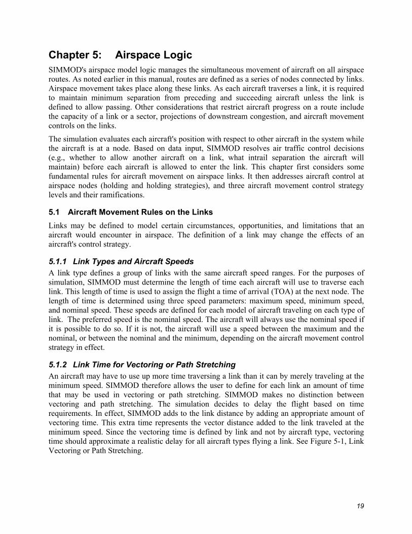
The third strategy, in addition to checking the number already holding at the next queue, considers the number approaching the node to see if the next holding queue is scheduled to be full by the time the aircraft would arrive. See Figure 5-6, Holding Strategy 3.
Figure 5-6: Holding Strategy 3
5.3 Aircraft Movement Control Strategies There are three strategic levels of aircraft movement control. A movement control strategy is a logical approach to controlling aircraft traffic in airspace. Each different strategy or mix of strategies can have different effects on aircraft movement, and so may be applied to resolve different kinds of conflicts.
Control strategies will only be applied when an aircraft is ready to enter a new link, and this can only occur when the link has unfilled capacity.
The control strategies are as follows:
• Level I Node Arrival Control - Type 1: QFIFO - Type 2: SpeedFit - Type 3: MultiFit
• Level II Metering Control - Type 1: Basic
• Level III Flow Control - Type 1: Basic
25
Generally speaking, the higher numbered, more complex strategy levels use more sophisticated logic and require more data input. They are usually not needed at all nodes and will increase run time considerably if applied universally.
The Level I strategy is referred to as Node Arrival Control. Note, however, that all strategies involve node arrival decisions to some extent. This level of strategy includes three alternate strategy types. Each node can have a different type of Level I strategy, but one must be defined for each node.
Any Level I strategy will work in unison with the Level II and Level III strategies. Levels II and III include only one type of strategy each, and these are optional.
5.3.1 Level I: Node Arrival Control Strategies
5.3.1.1 Type 1: QFIFO Node Arrival Control The first node arrival control strategy, QFIFO, is the simplest. Called QFIFO to indicate that the first into the queue is the first out, this type of control is the default for the simulation and should be used unless more control is specifically required.
The QFIFO control is straightforward. Every aircraft approaching a node is always put at the end of the node arrival queue. This can back up the air traffic. An aircraft may be required to wait at its current node until proper separation can be achieved in relation to aircraft preceding it on the next link, or in relation to aircraft preceding it in the node arrival queue (e.g., aircraft arriving from other converging links).
QFIFO works best for nodes with a single link approaching them or in cases where passing is not allowed on a link. The QFIFO Logic searches for the last aircraft currently in the node arrival queue and reads its TOA.
To enter the node arrival queue, the next aircraft must have a later TOA and the difference in TOA's must be sufficiently large to ensure that minimum separation is maintained by the two aircraft.
The entering aircraft's TOA is calculated using the nominal speed. See Figure 5-7, QFIFO Logic with No Delay.
26

Figure 5-7: QFIFO Logic with No Delay
If this nominal time is still too early, the simulation delays (i.e., contrives to add time to) the TOA, as described below.
5.3.1.2 Order of Delays Generated for QFIFO. The QFIFO strategy first creates delay by slowing down the aircraft so that it flies the link between the nominal speed and the minimum speed. The delay is the difference between the nominal time and the time required to fly the link at the lesser speed. See Figure 5-8, QFIFO Logic with Speed Delay.
Figure 5-8: QFIFO Logic with Speed Delay
27

If this delay is not sufficient to yield adequate separation, the aircraft will fly the link at the minimum speed and attempt to create the additional delay by vectoring. The vectoring delay includes the delay from traveling at the minimum speed and the additional delay from vectoring (i.e., path stretching) on the link. See Figure 5-9, QFIFO Logic with Vectoring Delay.
Figure 5-9: QFIFO Logic with Vectoring Delay
If this is still not sufficient, the aircraft will hold at the current node until it can traverse the link at the minimum speed with the vectoring delay. See Figure 5-10, QFIFO Logic with Holding Delay.
Figure 5-10: QFIFO Logic with Holding Delay
28
Using QFIFO thus involves the following restrictions:
• Each aircraft must maintain separation from the aircraft before it in the queue. • Aircraft must not violate the minimum or maximum speeds. • Aircraft TOA's can include the vectoring delay only if light/heavy sequencing is not
in effect. (Since each new aircraft will be assigned to the last position in the queue, light/heavy sequencing provides no additional control and should not be used where QFIFO is in effect.)
QFIFO uses the following order of steps to fit an aircraft in the last position in a queue:
1. Try to make it fit at nominal speed. 2. Try to make it fit at decreased speed. 3. Try to make it fit at decreased speed using vectoring (if allowed). 4. Make it fit at decreased speed using vectoring (if allowed) and holding delay.
5.3.2 Level I: Node Arrival Control Strategies, Continued
5.3.2.1 Type 2: SpeedFit Node Arrival Control The second node arrival control strategy is called SpeedFit because any aircraft entering the node arrival queue can adjust its speed (within its allowable speed range) to fit into any position in the queue that allows adequate separation between the preceding and succeeding aircraft. SpeedFit only changes the speed of the aircraft entering the queue. It cannot change the speed or TOA of any other aircraft in the node arrival queue.
SpeedFit offers more possibilities and yields major improvements if certain conditions exist, e.g., if aircraft are approaching a node from more than one link, or if there is a mix of approaching aircraft with significantly large speed differences and sufficiently wide speed ranges to allow passing to occur.
In the SpeedFit logic, an aircraft's initial position in the queue is projected based on nominal speed. A check is done to see if this aircraft's "nominal" position violates any requirements set up for the airspace system. Such violations could include, for example: lack of separation with an aircraft already in the queue; passing an aircraft on a link where passing is not allowed; or sequencing a light behind a heavy aircraft.
The simulation can attempt to fit the aircraft into this nominal position by adjusting the aircraft's speed (within its range) and by applying path stretching (if this is allowed). See Figure 5-11, SpeedFit at Nominal Position with Speed Increase.
29
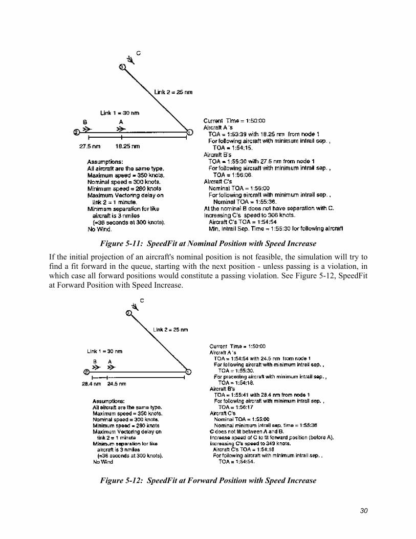
Figure 5-11: SpeedFit at Nominal Position with Speed Increase
If the initial projection of an aircraft's nominal position is not feasible, the simulation will try to find a fit forward in the queue, starting with the next position - unless passing is a violation, in which case all forward positions would constitute a passing violation. See Figure 5-12, SpeedFit at Forward Position with Speed Increase.
Figure 5-12: SpeedFit at Forward Position with Speed Increase
30
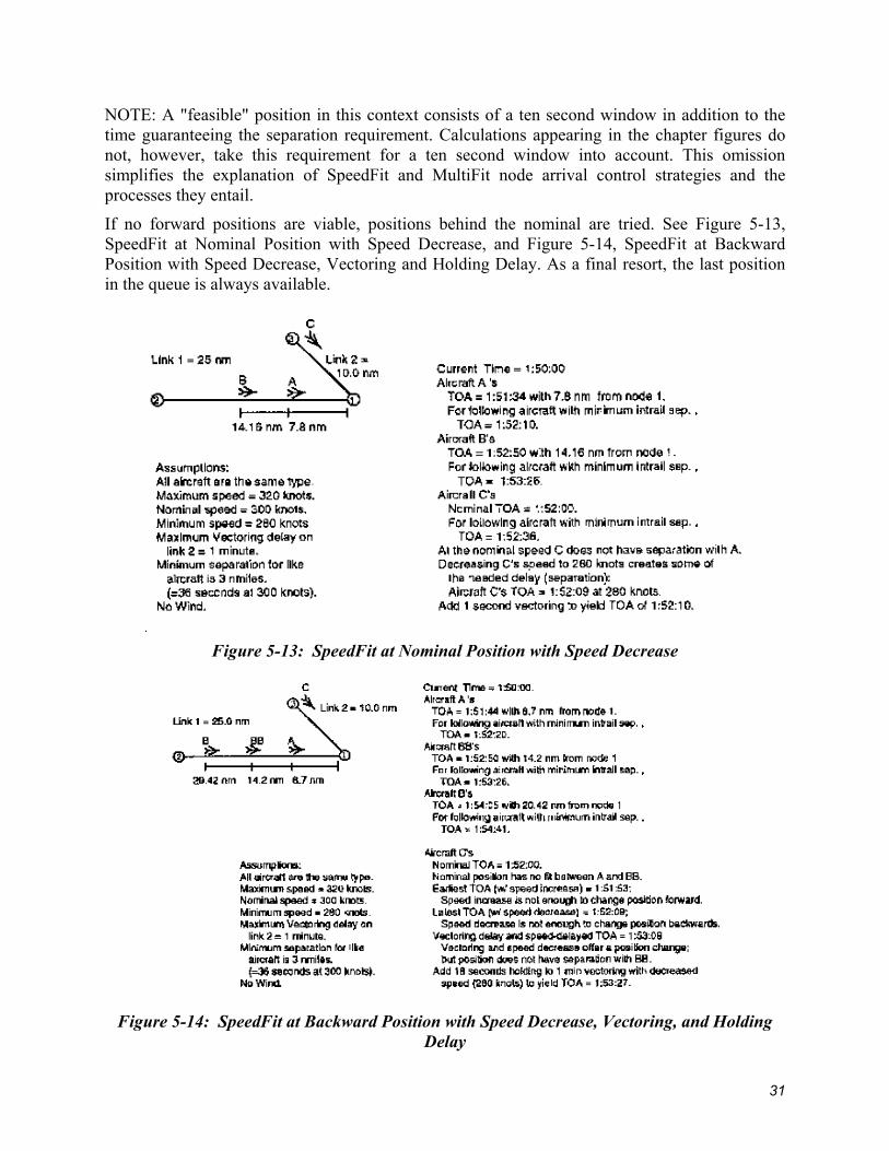
NOTE: A "feasible" position in this context consists of a ten second window in addition to the time guaranteeing the separation requirement. Calculations appearing in the chapter figures do not, however, take this requirement for a ten second window into account. This omission simplifies the explanation of SpeedFit and MultiFit node arrival control strategies and the processes they entail.
If no forward positions are viable, positions behind the nominal are tried. See Figure 5-13, SpeedFit at Nominal Position with Speed Decrease, and Figure 5-14, SpeedFit at Backward Position with Speed Decrease, Vectoring and Holding Delay. As a final resort, the last position in the queue is always available.
Figure 5-13: SpeedFit at Nominal Position with Speed Decrease
Figure 5-14: SpeedFit at Backward Position with Speed Decrease, Vectoring, and Holding
Delay
31
SIMMOD always adjusts the nominal speed by the minimum amount required to meet the separation requirements. If there is room for an aircraft at a position in the node arrival queue, the simulation will choose a speed closest to the nominal speed. If the position is forward in the queue, the speed will be the slowest speed allowing separation from the aircraft behind. Otherwise, the speed is the fastest speed allowing separation from the aircraft in front.
Thus, each aircraft to be placed into a queue position by SpeedFit is subject to the following restrictions:
• Only the aircraft entering the queue can be adjusted to make a fit. • Each aircraft must maintain separation from the aircraft before and after it in the
queue. • Aircraft must not violate the minimum or maximum speeds to achieve position. • Aircraft position can include the vectoring delay where light/heavy sequencing is not
in effect. • Aircraft positions after the nominal position can include holding delay.
SpeedFit uses the following order of steps to fit an aircraft in a queue:
1. Try to fit in the nominal position in the queue: • Use nominal speed • Increase speed • Decrease speed • Decrease speed and apply vectoring (if allowed)
2. Try to fit in a position forward from the nominal in the queue: • Increase speed • Try to fit in a position back from the nominal in the queue: • Decrease speed • Decrease speed and apply vectoring (if allowed) • Decrease speed and apply vectoring (if allowed) and holding delay
3. Fit in the last position in the queue (always available): • Decrease speed • Decrease speed and apply vectoring (if allowed) • Decrease speed and apply vectoring (if allowed) and holding delay
5.4 Level I: Node Arrival Control Strategies, Continued
5.4.1 Type 3: MultiFit Node Arrival Control The third node arrival control strategy, MultiFit, takes the SpeedFit control a step further. MultiFit attempts to fit an aircraft at each position by adjusting other aircraft in the queue. To try to make a fit, MultiFit adjusts not only the speed of the individual aircraft entering the node arrival queue, but also the speeds of aircraft preceding and succeeding it in the queue.
If no fit is found at a position, the preceding and succeeding aircraft speeds are returned to their original values and the next position is tried. First the nominal position is tried for a fit, then the positions forward from nominal, and finally backwards from nominal. When attempting to fit forward or backward, positions are attempted one by one, starting with the position closest to the nominal. Each attempt to fit an entering aircraft into a given position involves an exhaustive
32

application of the appropriate logic. The last resort for an entering aircraft is the end of the queue.
The speed adjustment of an aircraft already on a link is called a re-set. MultiFit control is one of two places where the simulation is allowed to adjust an aircraft's speed and vectoring in mid-link. Re-set can increase speed, decrease speed or add vectoring. The change of speed is only applied to the portion of the link that the aircraft has left to travel. Vectoring can add the total amount of vectoring time possible on the link, unless the aircraft in question is already vectoring; then only the portion not already allocated to vectoring can be added to the aircraft.
Thus, each time an aircraft is to be placed into a queue position by MultiFit, the following restrictions apply:
• For each queue position, only three aircraft can be adjusted: • The aircraft entering the queue • The aircraft preceding the entering aircraft in the queue • The aircraft succeeding the entering aircraft in the queue. • Every adjusted aircraft must have separation with aircraft before and after it in the
queue. • No adjusted aircraft may violate the minimum or maximum speeds to achieve
position. • An aircraft's adjusted position can include the vectoring delay only if light/heavy
sequencing is not in effect. • Only the aircraft entering the queue can include holding delay to achieve a position
after nominal position.
MultiFit uses the following steps to fit an entering aircraft in a queue:
1. Try to fit the aircraft into its nominal position in queue: • Use nominal speed of entering aircraft • Increase speed of entering aircraft • Decrease speed of entering aircraft • Decrease speed of entering aircraft and add vectoring delay (if allowed) • Increase speed of preceding aircraft; adjust entering aircraft by decreasing speed and
vectoring (if allowed)
Adjust the succeeding aircraft by decreasing speed and vectoring (if allowed); adjust the speed of the entering aircraft by decreasing its speed and vectoring (if allowed) or by increasing its speed
Increase speed of preceding aircraft; adjust the succeeding aircraft by decreasing speed and vectoring (if allowed); adjust the speed of entering aircraft by decreasing speed and vectoring (if allowed) or increasing speed
Figure 5-15 shows how the MultiFit strategy logic might fit an aircraft in a nominal queue position by increasing the speed of the aircraft preceding it in the node arrival queue. Figure 5-16 shows how the MultiFit strategy logic might fit an aircraft in a nominal queue position by decreasing the speed of the aircraft succeeding it in the node arrival queue.
33
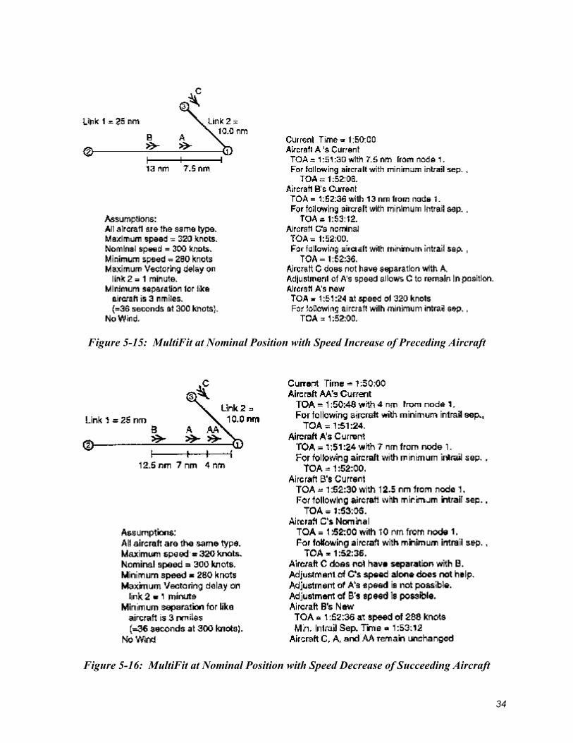
Figure 5-15: MultiFit at Nominal Position with Speed Increase of Preceding Aircraft
Figure 5-16: MultiFit at Nominal Position with Speed Decrease of Succeeding Aircraft
34

2. Try to fit an aircraft into one of the positions forward from nominal in queue, starting with the position closest to nominal: • Increase speed of entering aircraft • Increase speed of preceding aircraft; adjust entering aircraft by increasing speed • Adjust the succeeding aircraft by decreasing speed and vectoring (if allowed);
increase the speed of entering aircraft • Increase speed of preceding aircraft; adjust the succeeding aircraft by decreasing
speed and vectoring (if allowed); increase the speed of entering aircraft
3. Try to fit an aircraft into one of the positions backward from nominal in queue, starting with the position closest to nominal: • Decrease speed of entering aircraft • Decrease speed of entering aircraft and add vectoring delay (if allowed) • Decrease speed of entering aircraft and add vectoring (if allowed) and holding delay • Increase speed of preceding aircraft; adjust entering aircraft by decreasing speed,
vectoring (if allowed) and holding • Adjust the succeeding aircraft by decreasing speed and vectoring (if allowed); adjust
the speed of entering aircraft by decreasing speed, vectoring (if allowed) and holding or by increasing speed
• Increase speed of preceding aircraft and adjust the succeeding aircraft by decreasing speed and vectoring (if allowed); adjust the speed of entering aircraft by decreasing speed, vectoring (if allowed) and holding or by increasing speed. (See figure 5-17 and the accompanying description of the example)
35

Figure 5-17: MultiFit at Back Position, Speed Decrease of Succeeding Aircraft
4. Fit an aircraft into last position in queue: • Decrease speed of entering aircraft • Decrease speed plus vectoring (if allowed) of entering aircraft • Decrease speed plus vectoring (if allowed) and holding delay of entering aircraft • Increase speed of preceding aircraft and adjust entering aircraft by decreasing speed,
adding vectoring (if allowed) and holding delay
36
5.5 Level II: Metering Strategy Metering Strategy is an optional strategy that enhances the simulation's ability to control aircraft movement. It models the processes by which a controller looks ahead along the route network and handles projected downstream traffic.
The basic airspace movement rules allow the simulation to coordinate aircraft approaching each node on a route. Metering allows the simulation to see downstream congestion by projecting aircraft positions at key nodes along a route. Based on the projection, the simulation will attempt to space aircraft to minimize downstream congestion or divert aircraft to a less congested route.
Metering is limited in that its adjustments must be carried out within the constraints established by the operative node arrival control strategy; for example, it cannot change the sequence of an aircraft in the node arrival queue if this has already been established by the Level I node arrival control strategy.
Metering Strategy is discussed below in two sections: Metering Node Structure and Metering Logic.
5.5.1 Metering Node Structure To use meter control, certain nodes are designated as meter post nodes and others as meter nodes.
Post nodes are generally located at bottlenecks or critical merge points in the airspace network. Each post node is associated with a group of meter nodes, which are located before it on the airspace route(s). Specifically, meter nodes are located at points along a meter controlled route where the simulation should invoke the meter control (Level II) strategy. (Other routes, which are not heading for the meter post node and are not associated with it, may happen to include a meter node, but these routes are not controlled by the metering strategy.)
A meter post node should be located at a critical merge point in the airspace where normal airspace movement controls might not be capable of managing aircraft delay - the node immediately prior to the airport interface, for example. The simulation allows any airspace node to be defined as a meter post node.
Another consideration in locating the meter post node is this node's role in diverting aircraft to alternative routes. The analyst may cause metered aircraft to be diverted to an alternate route based on the number of aircraft expected to arrive at the meter post node. Similarly, the analyst may deny aircraft from other routes any access to a specific metered route based on the number of aircraft due to arrive at this post node.
A meter node should be located at a point where meter control logic can successfully initiate the control of downstream traffic, i.e., it should be a node sufficiently far upstream from the post node to allow aircraft adequate space and time to meet minimum separation requirements by the time they reach the post node.
Note, however, that meter nodes should not be located at the outermost airspace nodes: aircraft should not enter the simulation at a meter node.
The route list for a meter node should be the routes passing through that meter node and heading for its post node. Any other routes should be left out of the meter node's list. Refer to figure 5-18, Metered Airspace.
37

Figure 5-18: Metered Airspace
5.5.2 Meter Logic Any aircraft between a meter node and its post node on a meter-controlled route is subject to meter control actions.
Meter controls function in cooperation with the (Level I) node arrival control. As each flight progresses along a route, node arrival control is exercised at each node. If the flight is on a metered route, metering control is in effect from the time the flight approaches the meter node on a link until it passes through the post node.
When an aircraft subject to metering arrives at a node, the node arrival control logic is first applied to determine the aircraft's movement to the next node along the route and its position in the next node's arrival queue.
Next, the meter control logic (Level II) "looks ahead" to the post node for the route. It projects the status of traffic at this post node at the aircraft's arrival time, assuming the aircraft will travel at nominal speed beyond the next node. All traffic converging on the post node is considered in this look-ahead.
Meter control must maintain each aircraft's relative position in the next node's arrival queue as established by the node arrival control. If a future conflict with another aircraft is projected, meter control actions are taken to fully or partially alleviate the conflict.
38

Each meter post node has a meter queue in addition to its normal node arrival queue and node holding queue. An aircraft enters the meter post queue only if it is on a metered route and only after being placed in the node arrival queue for the initial meter node.
The meter post queue lists the aircraft approaching a meter post node in order of their projected TOA. The earlier the TOA at the post node, the more advanced an aircraft will be in the meter post queue. This projected TOA for an aircraft is the sum of the TOA in the node arrival queue at the meter node plus the time required by the aircraft to traverse all links between the meter node and meter post node at nominal speed.
However, the meter control cannot change the relative position (i.e., the sequence) of the new aircraft in the meter queue, nor can it change the nominal time required by the aircraft to traverse the intermediate links. Consequently, any adjustment of a TOA in the meter queue must be made by changing the aircraft's TOA in the current node arrival queue.
Meter control adjustments cannot change the sequence of any aircraft in the node arrival queue either, but they can change the entering aircraft's specific TOA insofar as is possible without violating its separation requirements. If the new aircraft in the meter queue is inadequately separated from only one aircraft in that queue (either the immediately preceding or succeeding aircraft), the meter control will attempt to fill this separation requirement by reducing the new aircraft's separation from the other aircraft to the minimum required. The difference saved will provide extra - but not necessarily adequate - separation time where it is needed.
If an aircraft entering the meter queue has inadequate separation from both the preceding and succeeding aircraft, the meter control will not attempt to ensure separation from either. The node arrival logic always limits the meter logic somewhat by establishing the sequence of aircraft in the node arrival queue. The node arrival control strategy that least inhibits the meter logic is QFIFO, because QFIFO always places the aircraft last in the node arrival queue. With an aircraft in this position, the meter logic can always attempt to resolve conflicts at the post node by delaying the aircraft at the current node.
The other node arrival control strategies, SpeedFit and MultiFit, might place the aircraft in a position that does not allow for the resolution of the metering queue separation requirements. Although only one meter control has been programmed to date, the modular design of the program will facilitate the addition of new types of meter control.
As mentioned above, aircraft may be diverted to alternate routes depending on the level of congestion projected at the meter post node. This projection is based on the number of aircraft in the meter post queue. In order for aircraft to be diverted to alternate routes, the user must specify the change to an alternate route via the plan record. (For more details, see "Dynamic Airspace" in chapter 7, "Interface Logic").
5.6 Level III: Flow Control Strategy Flow control strategy (Level III strategy) constrains traffic flow by adjusting separation distances at nodes on the boundary of the defined airspace. It aids in balancing the flow of traffic into the modeled airspace to prevent those congestion problems that cannot be reasonably handled by node arrival control or meter control. This level of control is optional.
39

5.6.1 Flow Control Node Structure Flow control designates certain nodes as flow post nodes and others as flow nodes. Generally the flow post nodes are bottlenecks or critical merge points in the airspace network. Each flow post node is associated with a group of flow nodes.
Flow nodes are entry nodes to the modeled airspace that feed traffic to the flow post node. Each flow node is associated with a route or routes under flow control. Flow control strategy specifies such parameters as the average speed of traffic flowing through each flow post node and the average speed through each of its associated flow nodes. It also sets the minimum and maximum separation distance settings at each flow node as well as the distance increment to which separations will be rounded. See Figure 5-19, Flow Controlled Airspace.
Figure 5-19: Flow Controlled Airspace
5.6.2 Flow Control Logic Flow control separation distances are updated at regular time intervals to keep up with the status of traffic loading and airport operation changes. The time intervals of these flow update events are specified by user input.
When a flow update event occurs, the program computes the number of aircraft expected to flow through each flow post node during the time period until the next flow update. It also computes the number of aircraft generated by the simulation that are nominally expected to arrive at each
40

of the associated flow nodes. Intrail separation distances at each of the flow nodes are set so that the sum of the flows through the associated flow nodes equals the flow through the flow post node. The flow settings of the flow nodes are proportional to their traffic loads.
Although only one type of flow control strategy has been programmed to date, the modular design of the program allows for additional types to be added easily.
41

This page intentionally left blank.
42

Chapter 6: Airfield Nodes and connecting links define SIMMOD airfield structures:
• Runways • Departure queues for holding and sequencing aircraft departing on runways • Gates for loading and unloading aircraft • Taxipaths for aircraft movement between gates and runways • Towing areas • Runway crossings • Dynamic single direction (DSD) paths
Airfield nodes are points in a two-dimensional coordinate system (corresponding to a basically flat airfield). The only attributes assigned to every node are its latitude and longitude (the x,y coordinates). Airfield nodes typically mark taxipath intersections, runway exits or crossings, gates, towing areas, de-icing areas, staging areas, taxi checkpoints, and departure queues. Airfield links describe taxipaths, runways, runway exit paths, and departure queue paths. Figure 6-1 shows an airfield network with gates, taxipaths, runways, and runway exits.
Figure 6-1: Airfield Network
The link is the more consequential of airfield structures. The attributes of the airfield link are significant in determining aircraft movement. Links are defined by their initial and final nodes; in addition to its length, each link has the following attributes:
• Assignment to arriving aircraft, departing aircraft, or both • Maximum number of aircraft allowed on the link • Passing rules (no passing, passing in one direction only, passing in both directions) • Aircraft groups allowed on the link • Direction of aircraft movement (from initial to final node, from final to initial node,
or both directions) • Taxi speed on the link, in knots
43

6.1 Runways A runway is defined as a list of links from one end to the other. Runway links are defined in one direction and may be used in both directions.
6.1.1 Runway Exits Runway exits can be defined at the end of each link on a runway. Which runway exit is used for any simulated landing depends on where the aircraft finishes its landing roll. Any exit reached after completion of the roll is a viable exit. The taxipath optimization logic selects the specific exit.
A link connected to the runway may be defined as a high-speed exit. These are frequently used to reduce runway occupancy time. The difference between the headings of the link and the runway determines the amount of the landing roll that may be completed on the high-speed exit.
Amount of Landing Roll Completed on High Speed Exit
Change in Heading % of Roll Completed
10 deg 20%
20 deg 15%
30 deg 10%
40 deg 5%
6.1.2 Runway Blockage When an aircraft is performing a takeoff or landing roll on a runway, all links and nodes of the runway are blocked to other aircraft taking off or landing (see figure 6-2).
Figure 6-2: Runway and Taxipath Interaction
Before an arriving flight lands on the runway, it also blocks aircraft from crossing the runway. This blocking begins before the arrival lands on the runway by a period of time defined as the expected runway delay time. This is generally equivalent to the length of time an aircraft requires to cross the runway, because all runway crossings should be finished by the time the arrival touches down. The blocking ends at each node on the runway as the landing aircraft passes it, unless a user-defined procedure determines otherwise (see Chapter 7, Interface Logic).
44

For departures, blocking begins before the takeoff is cleared to depart by the expected runway delay time. The blocking ends at each node on the runway as the departing aircraft passes it, unless a user-defined procedure determines otherwise.
6.1.3 Runway Crossing Priority Landing and departing aircraft have priority for using the runway and may continually block aircraft from crossing based on the spacing of the landings and takeoffs. However, the simulation parameters can be reset to give priority to runway crossings. Depending on the number of aircraft waiting to cross and the time any aircraft has been forced to wait, SIMMOD can adjust the intrail separation of arriving aircraft to force a break. Small changes are made dynamically as needed. The change is specified as either an increase to aircraft inter-arrival times, or as an increase in the separation distance between arrivals. The requirements for establishing larger changes in arrivals are covered in the section "Setting Conditions for a Forced Runway Crossing" in Chapter 8, Resetting Simulation Parameters.
6.1.4 Runway Crossing Times Optional logic exists in SIMMOD to allow the user to model runway crossings from hold line to hold line. The optional RWYCROSS record of the Airfield file allows the user to assign specific runway crossing times and characteristics to each runway crossing. SIMMOD's runway crossing logic will check departing and arriving aircraft before allowing an aircraft to cross the runway.
If the RWYCROSS logic is not used, SIMMOD uses the DefDly value of the RUNWAY record to determine the amount of time a plane needs to cross the runway. A plane will be allowed to cross the runway as long as it can finish crossing by the time an arrival or departure reaches the same crossing node. The SETXNG record may also be used to give priority to crossing planes. Refer to Chapter 8 "Resetting Simulation Parameters" of this manual for details of SETXNG.
A global variable, RC_Fudge_Time, in the GLOBAL record provides additional flexibility when using the runway crossing logic. This constant value, in seconds, is subtracted from the total time SIMMOD has calculated for an aircraft to cross a runway. This allows the user to reduce the window of time an aircraft requires before it may attempt a runway cross. Once an aircraft is crossing the runway, the departure queue will hold departing aircraft until the runway crossing is completed (see figure 6-3). This global option only works with the runway crossing logic enabled. Coordination of runway usage is discussed in Chapter 7, Interface Logic .
45

Figure 6-3: Runway Crossing Logic Using the RC_FUDGE_TIME Global Variable
6.2 Gates Every aircraft entering the airfield is assigned to a gate. All gates are located at defined airfield nodes. Aircraft enter or leave the simulation at gates or towing areas. Once at the gate, a flight is held for the duration of at least one gate service time in order to model gate occupancy. This period of time accounts for either the loading or unloading of aircraft passengers and supplies. Gates are defined with a user-specified service time distribution, which is sampled for both loading and unloading.
If a flight uses towing (optional), aircraft will hold at the gate for an additional amount of time. This time is chosen from the gate towing time distribution in the TAMPS record and accounts for the additional time spent during the towing procedure. If the aircraft is a turnaround flight, the aircraft is held for the duration of both times, i.e., both are applied to the aircraft. Gate access restrictions can be set according to aircraft model or TAMPS group in the optional GATEUSE record. SIMMOD no longer restricts gate use by aircraft size.
6.2.1 Gate Ownership A gate can belong to an airline, to a group of airlines, or to all airlines. Every flight that enters the system is identified with an airline, and it can use only the gates available to that airline. Such gates include those specifically assigned to the airline and those available to all airlines. An arriving flight can be assigned to a specific gate, any gate owned by its airline, or left unassigned (i.e., able to use any available gate). A gate’s alternate-gate flag (the GFLAG field in the GATE
46
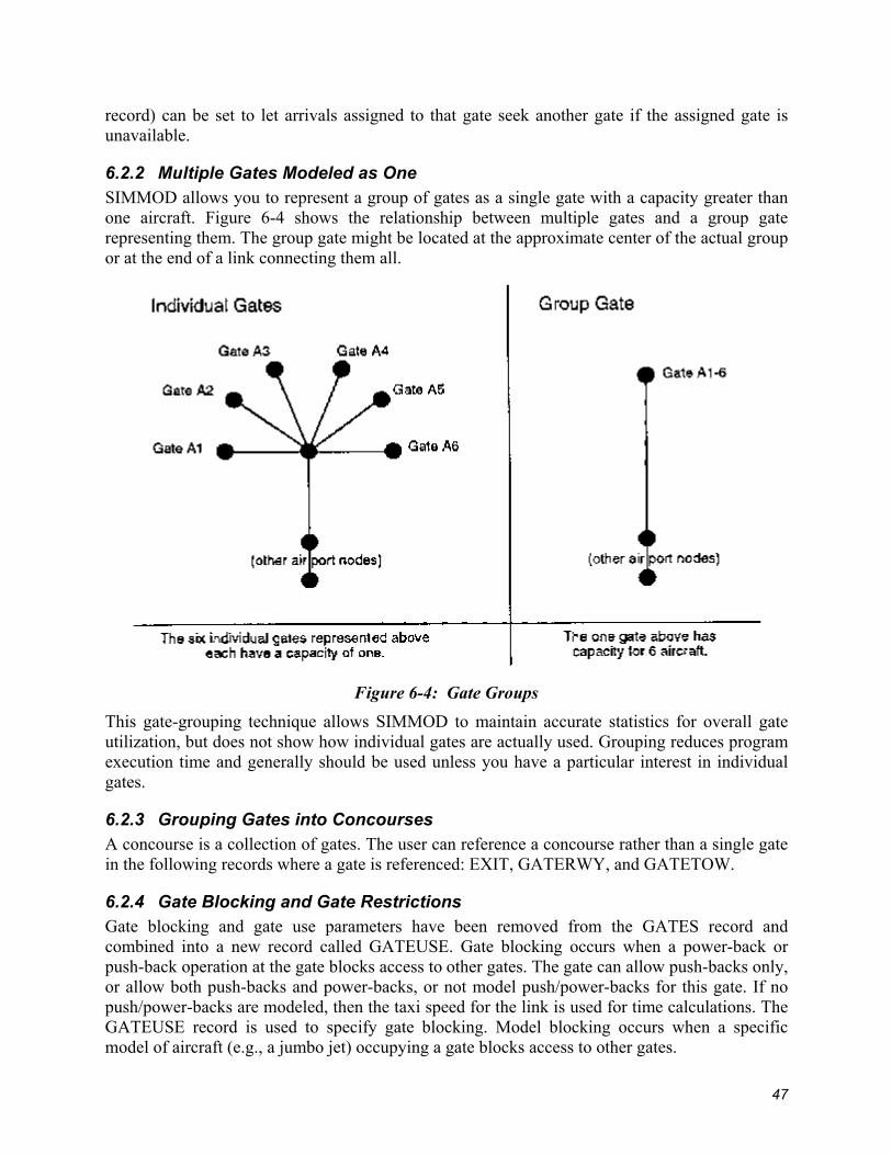
record) can be set to let arrivals assigned to that gate seek another gate if the assigned gate is unavailable.
6.2.2 Multiple Gates Modeled as One SIMMOD allows you to represent a group of gates as a single gate with a capacity greater than one aircraft. Figure 6-4 shows the relationship between multiple gates and a group gate representing them. The group gate might be located at the approximate center of the actual group or at the end of a link connecting them all.
Figure 6-4: Gate Groups
This gate-grouping technique allows SIMMOD to maintain accurate statistics for overall gate utilization, but does not show how individual gates are actually used. Grouping reduces program execution time and generally should be used unless you have a particular interest in individual gates.
6.2.3 Grouping Gates into Concourses A concourse is a collection of gates. The user can reference a concourse rather than a single gate in the following records where a gate is referenced: EXIT, GATERWY, and GATETOW.
6.2.4 Gate Blocking and Gate Restrictions Gate blocking and gate use parameters have been removed from the GATES record and combined into a new record called GATEUSE. Gate blocking occurs when a power-back or push-back operation at the gate blocks access to other gates. The gate can allow push-backs only, or allow both push-backs and power-backs, or not model push/power-backs for this gate. If no push/power-backs are modeled, then the taxi speed for the link is used for time calculations. The GATEUSE record is used to specify gate blocking. Model blocking occurs when a specific model of aircraft (e.g., a jumbo jet) occupying a gate blocks access to other gates.
47
Previously, SIMMOD users specified which aircraft models parked at certain gates block other gates. The logic associated with this blocking required that all aircraft at related gates be blocked if the user input gate blocking parameters. SIMMOD now allows users to specify that only certain model types at related gates may be blocked. For each gate, a list is created which specifies all the aircraft types that block other gates, along with the gates blocked and models blocked. This list also determines which aircraft can occupy the gate. This list is developed based on data fields provided in a new record called GATEUSE.
Link blocking occurs when a power-back or push-back operation at the gate blocks access to ground links near the gate. Each gate may define a list of links that are blocked during a power-back or push-back. When an arriving flight’s assigned gate is blocked, it can wait until the gate is available, or if the definition of the gate permits, it can seek an alternate gate.
Previous versions of SIMMOD used aircraft weight to determine whether or not an aircraft could access a gate. SIMMOD version 2.2 more realistically models gate access using aircraft model type to determine whether or not an aircraft may use a gate. This allows the user more flexibility in determining which aircraft may access which gates. Some gates at airports are not equipped to handle certain types of aircraft because of aircraft size or the need for specialized equipment.
6.2.5 Gate Logic Gate assignments for an individual flight can be determined by data input or left to SIMMOD. If gate blocking has occurred and alternate gating is an option, gate ownership limits the available choices in the simulation. The model of the aircraft is also a consideration. When a flight is created at an airfield or enters the airfield from the airspace, SIMMOD performs a gate check. The process for the check is as follows:
1. SIMMOD checks to see whether the flight is assigned to a specific gate. 2. If not, SIMMOD checks for available gates and assigns the flight to one at the first
possible time. 3. If the flight is assigned, SIMMOD checks the availability of that gate. 4. If the gate is available, it is reserved for the flight at its gate arrival time. 5. If the gate is not available, SIMMOD checks whether it is allowed to find an alternative
to this gate. 6. If SIMMOD cannot seek an alternate gate, it will reserve this gate at the first available
time. 7. If SIMMOD can seek alternates, it will search for available gates and reserve one for the
flight.
6.3 Links Certain aircraft may be restricted from using some airfield taxiways because of weight or size restrictions. In previous versions of SIMMOD, the taxipaths for an aircraft were chosen based on the weight of the aircraft. SIMMOD version 2.2 allows users to specify link travel restrictions based on aircraft model types or TAMPS groups. The default value allows all aircraft to use all links.
48

6.3.1 Taxipaths Taxipaths define the paths between runways and gates, and towing areas and gates. A taxipath is a series of links listed sequentially in the direction of travel. Taxipaths can be determined by the user in the TAXIPATH record, by a SIMMOD optimization routine, or by a combination of the two (when the user does not specify a complete taxipath in the TAXIPATH record).
6.3.1.1 User-Defined Taxipaths A user-defined taxipath lists a set of preferred links. If SIMMOD is to use a completely user-defined taxipath for an arrival, the taxipath must extend directly from the runway exit selected for that flight all the way to the defined gate. If the user specifies a partial taxipath, SIMMOD will apply its optimization routine to determine a complete taxipath. When SIMMOD determines the optimal taxipath because the user specified a partial taxipath, it may or may not include user-specified links.
Attempting to use a completely defined taxipath without allowing for optimization requires very strict definition of gates and runway roll distances; if changes occur in either of these, the taxipath is not complete. Each link on the airfield has defined characteristics that can preclude it as a viable taxipath option. For example, a link may be defined to handle arrivals only, or to handle traffic in one direction only when most of the actual flow of traffic is going in the opposite direction.
6.3.1.2 Assigning Taxipaths Depending on Gate, Runway, and Arrival/Departure Status
SIMMOD's optional GATERWY record allows the user to make gate/runway/arr_dep specific assignments in order to supplement the taxipath optimization logic. The GATERWY record may be used to assign a taxipath when the gate assignment is not known in advance. For instance, if SIMMOD chooses a random gate available to the flight's airline, the model may reference the GATERWY record to find a taxipath or partial taxipath that is suitable for that gate/runway/arr_dep combination.
6.3.1.3 Assigning Taxipaths Depending on Gate, Towing, and Arrival/Departure Status (Towing aircraft only)
SIMMOD's optional GATETOW record allows the user to make gate/towing/arr_dep specific assignments in order to supplement the taxipath optimization logic. The GATETOW record may be used to assign a taxipath when the gate or towing area assignment is, or is not, known in advance. For instance, if SIMMOD chooses a random gate/towing area available to the flight's airline, the model may reference the GATETOW record to find a taxipath or partial taxipath that is suitable for that gate/towing/arr_dep combination.
6.3.1.4 Optimized Taxipaths SIMMOD will optimize a flight's taxipath between a gate and runway based on the defined link characteristics, projected congestion, taxi time, and any partial taxipaths defined for the flight. SIMMOD evaluates the costs (in aircraft taxi time) of possible taxipaths and selects the path with the lowest cost. See figure 6-5, Taxipath Costs and Link Characteristics.
49

Figure 6-5: Taxipath Costs and Link Characteristics
It assigns a cost to every link in a taxipath. The cost is the time an aircraft requires to traverse it, plus any expected delay on the link at the time the aircraft is projected to be on it. The optimization starts from the point where the aircraft enters the taxi system.
Links are considered based on their heading. SIMMOD first checks the link pointing most directly to the destination of the taxipath. Each link is added to the existing path and the link's time to the cost of the path, or else the link is used to define a new alternative path.
During the optimization, partial paths are thus built and checked, and then stored in order of least cost. The path with the lowest cost is always the one to which the next link is added. The number of paths and length of each path can be limited by input, thus limiting the number of possibilities SIMMOD will try.
Each link in a user-defined taxipath assigned to an aircraft is given a zero cost. A fully defined taxipath will almost always be considered the optimal taxipath for a flight because of its zero cost.
It is sometimes beneficial to define a partial taxipath and specify it for a flight. SIMMOD will complete the taxipath with its optimizer. Links explicitly listed in the definition of a taxipath — even a partial taxipath — have zero cost.
6.3.1.5 Taxipaths and Link Characteristics The optimization of a flight's taxipath considers the characteristics of each potential link to determine which are viable. It then considers the costs of viable links at the time when the aircraft is projected to enter them.
If the link is flagged for arrivals only and the flight is a departure, the link will not be considered viable for the optimized path. Similarly, departure-only links will not be considered for arrivals.
50
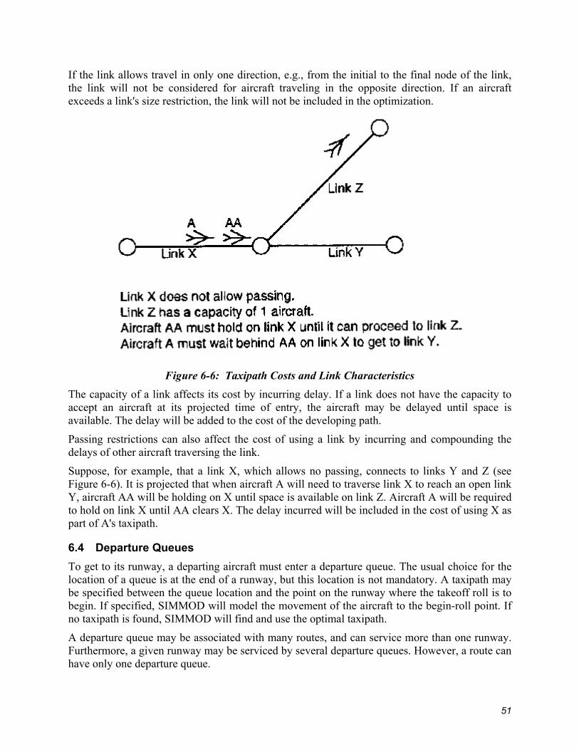
If the link allows travel in only one direction, e.g., from the initial to the final node of the link, the link will not be considered for aircraft traveling in the opposite direction. If an aircraft exceeds a link's size restriction, the link will not be included in the optimization.
Figure 6-6: Taxipath Costs and Link Characteristics
The capacity of a link affects its cost by incurring delay. If a link does not have the capacity to accept an aircraft at its projected time of entry, the aircraft may be delayed until space is available. The delay will be added to the cost of the developing path.
Passing restrictions can also affect the cost of using a link by incurring and compounding the delays of other aircraft traversing the link.
Suppose, for example, that a link X, which allows no passing, connects to links Y and Z (see Figure 6-6). It is projected that when aircraft A will need to traverse link X to reach an open link Y, aircraft AA will be holding on X until space is available on link Z. Aircraft A will be required to hold on link X until AA clears X. The delay incurred will be included in the cost of using X as part of A's taxipath.
6.4 Departure Queues To get to its runway, a departing aircraft must enter a departure queue. The usual choice for the location of a queue is at the end of a runway, but this location is not mandatory. A taxipath may be specified between the queue location and the point on the runway where the takeoff roll is to begin. If specified, SIMMOD will model the movement of the aircraft to the begin-roll point. If no taxipath is found, SIMMOD will find and use the optimal taxipath.
A departure queue may be associated with many routes, and can service more than one runway. Furthermore, a given runway may be serviced by several departure queues. However, a route can have only one departure queue.
51

In earlier versions, departure flights routed to an alternate runway would enter the airspace at the interface node adjoining the originally assigned runway; flights would thus “jump” from the end of the runway to an airspace node adjacent to a different runway.
SIMMOD 2.0 and later versions allow you to define fragmentary routes. A fragmentary route consists of the links beginning at the interface node adjacent to the secondary runway and ending at the first node belonging to the primary route. You must assign the fragmentary route to the departure queue servicing the alternate runway. See Figure 6-7, Alternate Runway Departures with Fragmentary Route Sections.
Figure 6-7: Alternate Runway Departures with Fragmentary Route Sections
Thus, when a departure flight is rerouted to an alternate runway, it enters the airspace at an interface node adjacent to the end of the runway and subsequently joins the original departure route. (For more details, see "Dynamic Airspace" in Chapter 7, "Interface Logic").
The capacity of the departure queue equals the capacity of the taxipath link(s) leading immediately into it. See Figure 6-8, Departure Queue Capacity.
52

Figure 6-8: Departure Queue Capacity
A departure queue is defined at a node, but aircraft waiting in the departure queue hold on the links leading into it. An aircraft is not considered in the queue unless it holds on one of the links immediately leading into the queue.
Thus, the capacity of the queue is the combined capacity of the taxipath links leading into it. Figure , Departure Queue Capacity figure, shows a departure queue with two links (links 2 and 3) leading to it. Each link has a capacity of three aircraft. The capacity of the queue is six aircraft.
However, aircraft on links 1, 4, and 5 are considered holding for the departure queue, though they are not in the departure queue. The time that aircraft on these links wait to enter the departure queue is added into the overall departure queue delay.
There are two departure queue strategies. The first is a strict first in, first out (FIFO) queue. The first aircraft in the queue is the only aircraft eligible to move out of the queue. No passing is allowed.
The second strategy allows an aircraft to pull out of the queue and move to its runway depending on runway or departure-queue availability, the aircraft’s position in the queue, and the aircraft's minimum and maximum departure time (if specified in the SLOTWINDOW record). If the first aircraft is not cleared to depart, SIMMOD will search back into the queue as far as permitted by the definition in the Departure Queue record.
53
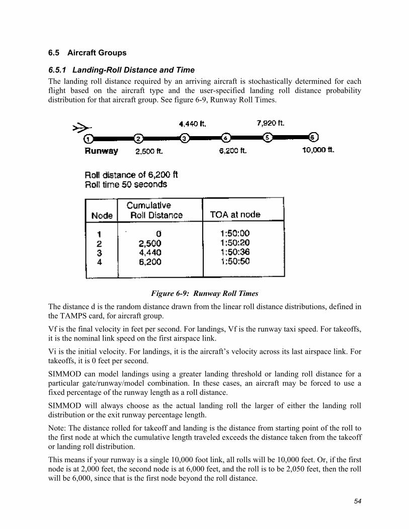
6.5 Aircraft Groups
6.5.1 Landing-Roll Distance and Time The landing roll distance required by an arriving aircraft is stochastically determined for each flight based on the aircraft type and the user-specified landing roll distance probability distribution for that aircraft group. See figure 6-9, Runway Roll Times.
Figure 6-9: Runway Roll Times
The distance d is the random distance drawn from the linear roll distance distributions, defined in the TAMPS card, for aircraft group.
Vf is the final velocity in feet per second. For landings, Vf is the runway taxi speed. For takeoffs, it is the nominal link speed on the first airspace link.
Vi is the initial velocity. For landings, it is the aircraft’s velocity across its last airspace link. For takeoffs, it is 0 feet per second.
SIMMOD can model landings using a greater landing threshold or landing roll distance for a particular gate/runway/model combination. In these cases, an aircraft may be forced to use a fixed percentage of the runway length as a roll distance.
SIMMOD will always choose as the actual landing roll the larger of either the landing roll distribution or the exit runway percentage length.
Note: The distance rolled for takeoff and landing is the distance from starting point of the roll to the first node at which the cumulative length traveled exceeds the distance taken from the takeoff or landing roll distribution.
This means if your runway is a single 10,000 foot link, all rolls will be 10,000 feet. Or, if the first node is at 2,000 feet, the second node is at 6,000 feet, and the roll is to be 2,050 feet, then the roll will be 6,000, since that is the first node beyond the roll distance.
54
The time at which an aircraft crosses each runway node is in proportion to the runway roll distance completed.
6.5.2 Takeoff Roll Distance and Time The takeoff roll distance required by a departing aircraft is stochastically determined for each flight based on the aircraft type and the user-specified takeoff roll distance probability distribution for that aircraft group. The time at which an aircraft crosses each runway node is in proportion to the runway roll distance completed.
6.5.3 Power-Back and Push-Back Aircraft. Each gate in an airfield may have an associated power-back and push-back distribution. These distributions allow the model to take into account the different times required for each of these activities. SIMMOD airfield links only allow one speed type; however, the time it takes to enter a gate is much briefer than the time it takes to "push-back" and unhook the tow. Power back and push back distributions adjust the simulation to account for these time differences. Users must specify which aircraft will push-back or power-back in the PPBACK record.
6.6 Congestion, Holdcycles, Checkpoints, and Staging Areas for Arrivals A congestion area is a set of links and gates used in staging operations when determining an aircraft’s movement after completion of its landing roll. If the congestion area is saturated, the aircraft will go to a staging area or holdcycle, depending on the level of staging you are modeling.
Staging areas are specified areas on the airfield where aircraft can park while waiting for their gateS to become free or for congestion levels in the gate area to decrease. In the GATES record users can specify that aircraft waiting for their gates to become free must go to a staging area before reevaluating gate status.
All staging areas must have an airfield node location and an airfield link that enters the node location. A staging area is defined as either a pad or a checkpoint.
A staging pad is an open area on the airfield where aircraft park to wait for an open gate. A pad must have a maximum number of aircraft allowed on the pad at one time, and a maximum number of aircraft allowed to queue for available room on the pad.
A checkpoint is usually located at the beginning of each taxipath contained in a holdcycle. A holdcycle is a group of user-defined taxipaths that form a circular path.
Upon the aircraft’s arrival at a checkpoint during a simulation, a decision is made by SIMMOD concerning the next movement of the aircraft. The decision depends on the current status of the congestion areas. The CHECKPOINT record includes the holdcycle number in which the checkpoint is a member, and a list of gates that can be accessed from this checkpoint.
Holdcycles are used in SIMMOD as a staging operation when an aircraft is not free to taxi directly to a gate upon completion of its landing roll. If the gate area is blocked, occupied, or congested, the aircraft will taxi in a defined holdcycle.
All holdcycles are defined by several checkpoint and taxipath pairs. Note that a holdcycle should be defined by taxipaths containing one link each. If a holdcycle consists of any taxipaths defined with two or more links, SIMMOD will use the taxipath optimization algorithm to obtain the
55

shortest route. This will defeat the intention of defining a specific holdcycle and will also increase computation time.
6.6.1 Staging Areas, Congestion and Taxi Checkpoints for Departures The departure staging logic of SIMMOD provides for routing the departing aircraft to a departure staging area if the number of aircraft assigned to the departure queue reaches the user-defined threshold level.
A departure staging area is an open area (pad) on the airfield where aircraft park. A staging area must have a maximum number of aircraft allowed on the pad at one time, and a maximum number of aircraft allowed to queue for available room on the pad.
If the capacity of the staging area and the capacity of the queue are exceeded, aircraft are sent to the staging area with a warning message. When the departure queue level drops below the threshold level, any aircraft in the staging area awaiting movement towards the departure queue is released to taxi from the staging area. Users should not use departure staging logic without taxi checkpoints.
Using departure congestion areas in conjunction with departure staging areas imposes an additional restriction on the movement of departing aircraft. A departure congestion area is a set of links leading to the departure queue. Although the departure queue level may be below the threshold level, high levels of congestion near the departure queue may necessitate the staging of the departing aircraft until the congestion eases.
If the departure queue, departure staging area, and departure congestion links are all at capacity, aircraft are held at their gates as a last resort. An aircraft is allowed to taxi towards the designated departure queue only if the departure queue level is below the threshold level and the related congestion levels are below the specified maximum levels.
Taxi checkpoints add additional controls for routing departure traffic. When a gate is assigned a departure staging area, aircraft exit the gate and taxi to the assigned staging area. Taxi checkpoints are user-specified ground nodes where aircraft can reevaluate their taxipath and choose either to continue to the departure staging area or taxi directly to the departure queue. Users can specify multiple taxi checkpoints along each taxipath, and the departure staging/departure queue decision will be reevaluated at each taxi checkpoint node.
6.7 Departure De-icing The SIMMOD de-icing logic models the de-icing process on a flight-by-flight basis at designated de-icing areas. For each departure queue, airport plan, and gate combination, the user specifies a list of the de-icing areas that can be used by a departing aircraft destined towards the queue. The de-icing area consists of a pad area where de-icing is performed and a queue area where the aircraft waits for de-icing.
When an aircraft requires de-icing, it is routed towards the chosen de-icing area. The first listed de-icing area would be chosen if there is room for the aircraft either in the pad area or the queue area. The user-specified de-icing list specifies the various de-icing areas to be used in order of priority. If all the de-icing areas are full, the aircraft will be sent to the last defined de-icing area in the list regardless of the de-icing area constraints. However, a warning message will be printed in the log file indicating that an aircraft was sent to a de-icing area in violation of its capacity restrictions.
56

Upon arrival of an aircraft at the de-icing area, it is deiced if there is capacity available at the pad area. Otherwise the aircraft occupies the queue area awaiting its de-icing turn. Upon completion of the user-specified delay for de-icing, the aircraft leaves the de-icing pad area and taxis towards the departure queue or the staging area based on departure staging considerations (see "Departure Staging Areas and Departure Congestion," above).
The de-icing logic also incorporates the capability of re-routing the aircraft for revisiting another de-icing station, if a user-specified de-icing active time has expired and SIMMOD has not yet scheduled the aircraft for takeoff. Re-routing is done if the aircraft is at the departure queue, staging area, or anywhere enroute to these waiting areas. If the aircraft is in the staging area queue, then it is rerouted once it occupies the passing position at the staging area. If an aircraft traversing a link is to revisit a de-icing station, rerouting is done upon its arrival at the next node.
6.8 Flight Banks SIMMOD uses flight banks to model the dependency of arriving and departing flights in hub operations. See figure 6-10, Bank Logic.
Figure 6-10: Bank Logic
A bank is a group of flights that are to be at their gates at the same time to allow passengers to make connections. SIMMOD does not limit the number of flights in a bank. If delays are encountered during the simulation, flights may not be able to make their connections at a hub. If a flight is part of a bank and is delayed in landing, some or even all other aircraft in the bank might be kept on the ground waiting for the late flight. Each departing flight in a bank makes the decision to wait based on four values:
• The user-defined maximum delay time that the flight can be held • The transfer time required by the connecting passengers after their plane has landed
(a stochastically adjusted value) • The probability that there will be a sufficient number of connecting passengers from a
heavy aircraft to justify delaying the departure
57

• The probability that there will be a sufficient number of connecting passengers from a large aircraft to justify delaying the departure
The following list represents the holding logic based on these values. Each dependent departure (i.e., each aircraft loaded and ready to pull back from its gate) considers the relative progress of each dependent arrival included in the mutual bank. The progress of the dependent arrivals is treated as follows:
• For a traveling flight (a flight traveling in the airspace/airport system but not currently at the gate), the departing flight is held if there are connecting passengers and the time required to land and transfer the passengers is less than the maximum hold time for the flight. Projected travel time is updated during the flight.
• For a queued flight (a flight queued for a gate but unable to unload), the departing flight is not held.
• For a gated flight (a flight at the gate but not finished unloading), the departing flight is not held if there are no connecting passengers or if the remaining transfer time is greater than the maximum hold time for the flight.
• The departing flight is held if there are connecting passengers and if the transfer time for the connecting passengers is less than the maximum hold time for the flight.
• For a flight finished unloading, the departing flight is not held.
6.9 Metalinks (no longer used, see DSDPath)
6.10 DSDPaths Dynamic Single Direction Paths(DSDPaths) are specified groups of connected ground links which may have multiple entry and exit points. DSDPath logic was implemented to allow a more realistic modeling of cul-de-sac and gate terminal traffic. Aircraft travel freely through the links with the restriction that no aircraft may pass another taxiing in an opposite direction. Each DSDPath has a specified capacity value to restrict the number of aircraft allowed on the path at a time. A capacity of one aircraft provides the same logic as the Metalink (see Metalink description above). If the capacity field is left blank or a 0 is specified, SIMMOD will not limit the capacity of the DSDPath.
58
Chapter 7: Interface Logic The interface logic controls aircraft as they land or take off, making the transition from airspace to airport or from airport to airspace. Coordinating flights, routes, and runways involved in these transitions involves complex processes. This chapter discusses airspace procedures and their relationship to runway management. It describes how SIMMOD models procedures, landings, missed approaches, takeoffs, and various route and runway management issues. Related procedures, "mated" aircraft landings on parallel runways, and SIMMOD's dynamic airspace re-routing capabilities are discussed in the latter part of this chapter. A landing aircraft requires a clear runway when it approaches within a certain distance of the airport. After touching down, it must then keep its path on the runway blocked to other aircraft until it has exited. The blocking prevents other aircraft from using the runway and may also limit the use of associated paths and runways. In SIMMOD's airspace structure, a route usually ends or starts at an airport; overflights are an exception. If the airport is described in detail the route will be "connected" to its runway using an interface node. This node signals the simulation that an aircraft arriving via this airspace route will continue by landing at an airport, and that appropriate control measures must be coordinated. A flight departing from an airport will be scheduled to pass through an interface node at the end of the runway. This signals the simulation that the airspace portion of the model must coordinate with the airport in controlling the flight.
7.1 Procedures In addition to any other node characteristics, an interface node is defined to have procedures associated with it. The procedures, in turn, define time and distance restrictions necessary to maintain a clear runway, plus any restrictions required to manage associated runways. A procedure is defined for every landing or takeoff that will be executed during the simulation. A procedure can be linked to other procedures to block other takeoffs or landings while the primary procedure is being executed. For example, a procedure may dictate the manner in which takeoffs and landings on the same runway exclude each other. An arriving aircraft coming within, say, two miles of the airport may block takeoffs from being released until the arrival is on the ground and has exited the runway. As soon as the landing has cleared, the takeoff is released. This takeoff might not only block landings while on the runway, it could also block all subsequent takeoffs until it was three miles away from the airport. A procedure constitutes permission for an aircraft to start a takeoff or landing. When an aircraft receives its permission, it blocks other aircraft from receiving theirs. The exact time and order for blocking and unblocking other aircraft determines the complex interactions required for runway management. The definition of any procedure includes two basic items of information: (1) the distance from the airport within which an aircraft will block runways and related procedures, and (2) the time interval after the start of an aircraft's runway roll within which the runway and related procedures must remain blocked. Additional information on these subjects appears under the description of Runway Blockage in Chapter 6, Airfield.
7.1.1 Landing For a landing aircraft, coming within a given distance from the airport constitutes a request for permission to land and initiates the blocking of certain other aircraft while the landing is occurring. Different distances can signal different procedures and restrictions for other types of runway management. For example, an arrival may request a procedure, i.e., permission to land, when three miles out from an airport and start blocking takeoffs at two miles out. The release of
59

blocking procedures varies according to the procedure. For example, a departure may be blocked from a runway for 60 seconds to account for the completion of a landing roll, while a departure on a crossing runway may be blocked for only 20 seconds to account for the landing aircraft passing by the intersection.
7.1.2 Missed Approach If a landing does not receive a clear procedure in response to a request, the missed approach logic is invoked. This may force the flight to pass the first interface node on a continuation route. The continuation route can circle back, perhaps reconnect with the route at some point, and allow the flight to try again; or it may divert the flight to another airport, or divert it to an exit in the airspace. If no continuation route exists, the aircraft will exit the simulation at that point. A low airport ceiling or too little runway visual range can also trigger a missed approach. Changes to weather conditions are considered in chapter 8, Resetting Simulation Parameters.
7.1.3 Takeoff A takeoff is usually restricted by landings. Landings, however, are rarely restricted by takeoffs. Landing aircraft naturally have priority for using the runway, the separation between landing aircraft having already been determined to a large extent by airspace separation requirements. Arriving flights could continually block aircraft from taking off or crossing a runway based on the spacing of the landings, except that simulation parameters can be reset to establish a priority for runway crossing. This is also discussed under Runway Crossing Priority in chapter 6, Airfield. A takeoff does block successive takeoffs, and this serves to keep departing aircraft separated in the airspace. However, it is also possible to develop different departure procedures that impose a sequence upon diverging departures. See Figure 7-1, Departure Control.
Figure 7-1: Departure Control
60
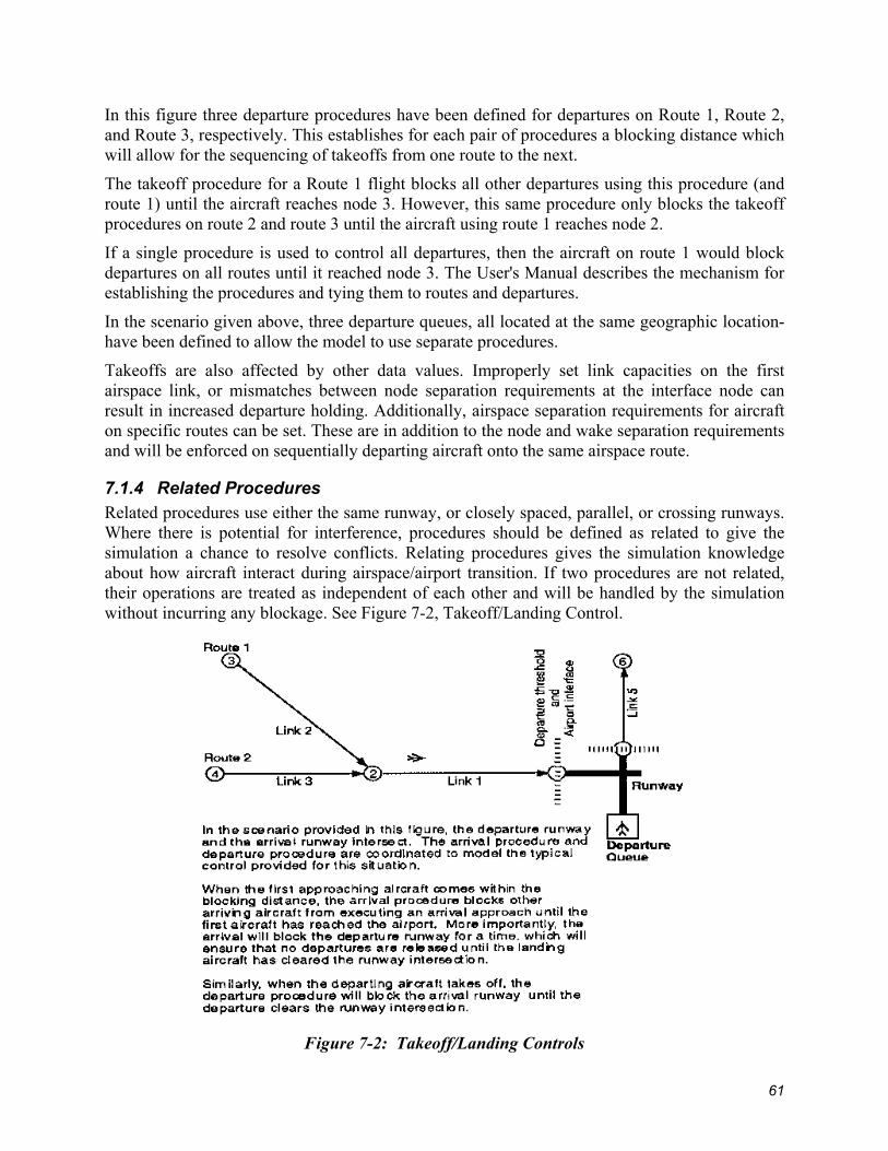
In this figure three departure procedures have been defined for departures on Route 1, Route 2, and Route 3, respectively. This establishes for each pair of procedures a blocking distance which will allow for the sequencing of takeoffs from one route to the next.
The takeoff procedure for a Route 1 flight blocks all other departures using this procedure (and route 1) until the aircraft reaches node 3. However, this same procedure only blocks the takeoff procedures on route 2 and route 3 until the aircraft using route 1 reaches node 2.
If a single procedure is used to control all departures, then the aircraft on route 1 would block departures on all routes until it reached node 3. The User's Manual describes the mechanism for establishing the procedures and tying them to routes and departures.
In the scenario given above, three departure queues, all located at the same geographic location-have been defined to allow the model to use separate procedures.
Takeoffs are also affected by other data values. Improperly set link capacities on the first airspace link, or mismatches between node separation requirements at the interface node can result in increased departure holding. Additionally, airspace separation requirements for aircraft on specific routes can be set. These are in addition to the node and wake separation requirements and will be enforced on sequentially departing aircraft onto the same airspace route.
7.1.4 Related Procedures Related procedures use either the same runway, or closely spaced, parallel, or crossing runways. Where there is potential for interference, procedures should be defined as related to give the simulation a chance to resolve conflicts. Relating procedures gives the simulation knowledge about how aircraft interact during airspace/airport transition. If two procedures are not related, their operations are treated as independent of each other and will be handled by the simulation without incurring any blockage. See Figure 7-2, Takeoff/Landing Control.
Figure 7-2: Takeoff/Landing Controls
61
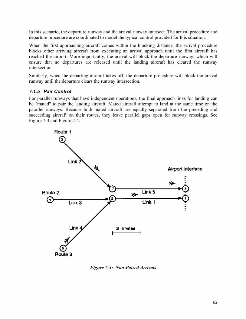
In this scenario, the departure runway and the arrival runway intersect. The arrival procedure and departure procedure are coordinated to model the typical control provided for this situation.
When the first approaching aircraft comes within the blocking distance, the arrival procedure blocks other arriving aircraft from executing an arrival approach until the first aircraft has reached the airport. More importantly, the arrival will block the departure runway, which will ensure that no departures are released until the landing aircraft has cleared the runway intersection.
Similarly, when the departing aircraft takes off, the departure procedure will block the arrival runway until the departure clears the runway intersection.
7.1.5 Pair Control For parallel runways that have independent operations, the final approach links for landing can be "mated" to pair the landing aircraft. Mated aircraft attempt to land at the same time on the parallel runways. Because both mated aircraft are equally separated from the preceding and succeeding aircraft on their routes, they leave parallel gaps open for runway crossings. See Figure 7-3 and Figure 7-4.
Figure 7-3: Non-Paired Arrivals
62

Figure 7-4: Pair Control, Paired Arrivals
7.1.6 Staggered Runway Approaches Instrument approaches on parallel runways that are separated by 2,500 to 4,300 feet may be conducted as long as diagonal separation of two nautical miles is maintained between adjacent aircraft. Additionally, simultaneous approaches to converging or intersecting runways (runways whose center-lines or extended center-lines intersect) are presently authorized during Visual
Meteorological Conditions (VMC). Both types of approaches require coordination and control to interleave the arrivals. The logic of the staggering option emulates the decision process of the ATC controller as aircraft are vectored onto final approach. To obtain proper spacing and sequencing in SIMMOD, the staggering of arrivals is exercised over the airspace links prior to the stagger control nodes. A step-by-step overview of the staggering logic is presented in the following paragraphs.
In Figure 7-5, node 3 and node 7 are mated stagger control nodes.
In this scenario consider only AC3 and AC1. AC3 will speed up on Link 3 because the amount of time it takes AC3 to travel from the stagger control node to the interface node is greater than the separation distance required between AC3 and AC1. The following text further illustrates this point.
• Assume simulation time = 1.0 • The time it takes AC1 to travel from the stagger control node to the interface node =
1.1
63
• The time it takes AC3 to travel from the stagger control node to the interface node = 1.5
• The separation time specified between these two aircraft models = .02 • Adding the travel time of AC1 to the separation time (1.1 + .02) = 1.12
Therefore, because time it takes AC3 to travel from the stagger control node and the interface node (1.5) is greater than travel time of AC1 and the separation time (1.12), AC3 can speed up on Link 3 while still maintaining the proper separation distance between the tow aircraft.
Remember, the separation distance must be maintained once the aircraft pass through the interface node and the aircraft will travel at nominal speed between the stagger control node and the interface node.
Conversely, if the time it takes AC3 to travel from the stagger control node to the interface node equals 0.9 then AC3 would slow down on Link 3 to maintain proper separation distance. If AC3 could not slow down enough prior to the stagger control node to maintain the separation distance, it would hold at node 3. Likewise, if congestion on the links between the stagger control node and the interface node would force AC3 to hold at a node (node 6 above) between the stagger control node and the interface node, AC3 would hold at the stagger control node.
The staggering option can only be activated if two (or more) airspace nodes on separate routes are mated as stagger control nodes. SIMMOD calculates the amount of time it will take an aircraft to travel from the stagger control node to the interface node at its nominal speed. In addition, SIMMOD will take into account any delay an aircraft would encounter due to link restrictions or congestion while traveling between the stagger control node and the interface node. Any changes to an aircraft's speed needed to maintain the separation distance and proper stagger control will be enforced on the links preceding the stagger control nodes. If an aircraft must hold to achieve proper spacing, it will hold at the stagger control node. Once an aircraft has passed through the stagger control node, trailing aircraft (on the same route or on a route with a mated node) will only be allowed to travel when the specified time separation can be maintained between the initial aircraft and the trailing aircraft after they pass through the interface node. Users should be aware that no dynamic re-routing can take place at or after the stagger control nodes. Ideally, the stagger control nodes should be placed two links before the interface nodes and equidistant from the interface nodes. See Figure 7-5, Stagger Control.
64

Figure 7-5: Stagger Control
65

7.1.7 Dynamic Airspace Re-routing Due to Runway Congestion Given (A) the appropriate metering logic to look ahead to the primary route's interface node and (B) a plan that incorporates a transitional route to another interface node, the simulation will try to re-route an aircraft in the airspace if the queue for its interface node is above capacity. Each route is allowed to define one or more transitional (i.e., re-routing) routes to another interface node. The metering control logic is used to check the flow and capacity at interface nodes to determine the need for re-routing. This requires that the interface nodes be meter post nodes. (Refer to chapter 5, Airspace Logic, for information on metering.) The primary meter post node queue has a capacity; when that is exceeded the model checks the transitional route. Transitional routes are defined by setting up one plan specifically to handle re-routing. The user must also specify the plan used for re-routing the traffic in the global data record PLN_DIVERSION_ROUTE_PLAN_NUM. If this record doesn't exist, you must create it. If there is sufficient capacity at the alternate metering post node (typically an interface node) to which the aircraft would be re-routed, and if the aircraft is not beyond the transition point for the transitional route, then the aircraft will be re-routed, i.e., it will take the transitional route. See Figure 7-6, Terminal Rerouting Airspace.
Figure 7-6: Terminal Rerouting Airspace
66

7.1.8 Dynamic Departure Re-routing Due to Runway Congestion When a flight is about to depart from its gate for its departure queue, a determination is made as to the departure queue length. If the length is greater than the departure queue's re-routing threshold, the simulation will attempt to reroute the flight. Re-routing will occur if a diversion route to the flight's assigned route has been specified in Dynamic Airspace Re-routing (as well as in the global data record PLN_DIVERSION_ROUTE_ PLAN_NUM), and if the diversion route's corresponding departure queue's length does not exceed its maximum length for accepting diverted flights. Since the diversion is on the ground, the movement to the alternative queue is handled by the simulation taxipath optimization utility.
7.1.9 Touch-and-Go Touch-and-go patterns can be modeled using SIMMOD. The touch-and-go logic was added for use in Navy simulations. First the user must create a touch-and-go set using the TNGSET record of the Airspace file, or by using the following menu path in the Network Builder: Edit : Airspace : Route : TOUCH_AND_GO_SET. A touch-and-go set consists of one or more patterns (sets of airspace nodes) which may be flown one or more times. The touch-and-go set must be assigned to an arrival flight in order for that flight to travel the touch-and-go patterns. The individual touch-and-go patterns must be created for each touch-and-go set. The touch-and-go patterns are defined with the PATTERN record of the Airspace file, or by the following menu path of the Network Builder: Edit : Airspace : Route : TOUCH_AND_GO. The touch-and-go pattern consists of a list of nodes and a threshold capacity value. Aircraft are allowed to travel the touch-and-go pattern only if the number of aircraft traveling the pattern (and traveling on a list of associated routes) is below this threshold value.
67

This page intentionally left blank.
68

Chapter 8: Resetting Simulation Parameters The conditions initially defined for a simulation may not hold true for the entire duration of the simulation. Some airports, for example, use the same runway for landings at one time and takeoffs at another. Similarly, a reversal of wind direction may require a significant change in plans. SIMMOD provides a means to model such changes.
When defining the simulation, it is possible to trigger changes to some of the conditions initially established for the airport and airspace system. This is accomplished with user-defined external events, usually just called "EVENTS" in the definition of input data. (External events are discussed in chapter 1, How SIMMOD Works.)
The user defines each such event and the time at which it is to occur in the simulation. These changes cannot be triggered by another condition, e.g., the length of a holding queue.
8.1 Flight Cloning (SETCLONE) This is described in Chapter 2, Flights.
8.2 Changing Gate Characteristics (SETGATE) The gate characteristics that may be changed include:
• List of airlines permitted to use the gate • Arrival unloading time distribution • Departure boarding time distribution
8.3 Inhibiting Injections (SETINJ) This feature essentially halts the creation of new arrival air traffic. All injections of aircraft into the airspace during the simulation are inhibited, i.e., annulled, for set periods of time. Using this single control can thus produce the same results as much more extensive changes to the arrival and departure data. The arrival and departure schedule for the time period is removed from the event schedule.
8.4 Changing Link Characteristics (SETLINK) The link characteristics that may be changed include:
• Length • Heading • Overtake flag • Wake turbulence flag • Capacity • Vectoring delay
Links are typically changed because of increased congestion occurring at certain times of the day or because of other changes in airport operations.
8.5 Changing Meter Post Node Characteristics (SETMETER) There is only one characteristic for a meter post node: the intrail separation for the node under metering logic.
69

8.6 Changing Node Characteristics (SETNODE) The node characteristics that may be changed include:
• Node arrival control strategy • Arrival strategy option flag • Intrail separation • Holding capacity • Holding strategy • Holding stack type
Nodes are typically changed because of increased congestion occurring at certain times of the day or because of other changes in airport operations.
8.7 Changing Plans (SETPLAN) An initial plan must be defined with the SETPLAN event before any flights occur. You are allowed one or more plan changes during the course of the simulation.
A plan change allows the operations of the simulation to change. The new plan may change airspace routes and divert aircraft to transitional or new routes.
Routes may be changed selectively. The plan change transition logic allows each route to have a transition path for aircraft already on the route. It also designates a "point of no return" beyond which a flight cannot make the transition. Flights beyond this point must finish on the original route. In addition, departures can be held until all aircraft in the airspace have either completed their transitions or exited the airspace.
An optional value of the SETPLAN record, PrePlanTime, may be used to transition departures to the new departure queue before the plan changes. Departure flights waiting in the old departure queue when the new plan takes effect will not be transitioned to the new departure queue by SIMMOD.
8.8 Inhibiting Procedures (SETPROC) Inhibiting procedures during the simulation blocks certain procedures from being used. Starting from the set simulation time, this feature prevents certain normally scheduled operations (designated by the user) from occurring. This generally results in missed approaches in the airspace and causes aircraft to be queued on the airfield at departure queues. This option may be used by the analyst to investigate a specific situation, such as when a runway is blocked by a stalled or damaged aircraft.
8.9 Changing Route Characteristics (SETROUTE) The only characteristic of a route that changes is its intrail separation. This can also be defined by plan for each route.
8.10 Changing Runway Characteristics (SETRWY) The runway characteristics that may be changed include:
• Landing roll distribution • Takeoff roll distribution
70

8.11 Changing Sector Characteristics (SETSECT) The only sector characteristic that changes is its capacity.
8.12 Controlling Touch-and-Go (SETTNG) This record provides the capability to control touch-and-go during the simulation. When the touch-and-go flag is on, the aircraft will perform touch-and-go, and will be removed from the simulation at the eject node of the touch-and-go pattern after completion of the touch-and-go.
8.13 Changing the Wind Characteristics (SETWIND) Wind conditions can be changed at any time during a simulation. Either the heading or speed or both can change.
8.14 Changing the Weather (SETWX) A change in the simulated weather involves changes to the airport ceiling or runway visual range. These can affect the landing and takeoff procedures and cause missed approaches. A change in the weather does not increase separations or spacing to account for weather conditions.
8.15 Setting Conditions for a Forced Runway Crossing (SETXNG) Setting a crossing resets the simulation to allow a flight to cross a runway when arriving flights would otherwise block the runway and all paths crossing it. Based on user-defined parameters, the simulation adjusts the intrail separation of arriving flights to create a break in the incoming traffic; this in turn creates an opening to cross the runway.
When the simulation is set to allow runway crossing, it monitors the number of aircraft waiting to cross and the period each waiting aircraft has been delayed. If a certain number of aircraft are waiting to cross, or if at least one aircraft has been waiting a certain amount of time, the simulation will force a break to allow a runway crossing.
71

This page intentionally left blank.
72

Chapter 9: Stochastic Processes SIMMOD is a stochastic model. Stochastic processes, in the form of random variables, are introduced into every iteration of SIMMOD to produce unique output representing day-to-day variations in air traffic phenomena. The amount of variation is determined by the input data.
Because SIMMOD is designed to produce realistic-not "ideal"-results from any single iteration of a defined application data set, it is often necessary to run several iterations with a single data set in order to establish statistically significant tendencies. For a run of several consecutive iterations, the SIMMOD Report Post-processor will produce aggregate values and, where appropriate, averages and standard deviations. For example, where frequencies indicating the usage of a given facility are reported for a single-iteration run, average frequencies will be reported for a multiple-iteration run.
9.1 Random Linear Variables SIMMOD uses random linear variables to reproduce the effects of random variation in airport and airspace system phenomena. The lateness of any given arrival or departure, for example, is introduced into the simulation processes as a random linear variable.
The simulation generates a random real number between zero and one. It then uses this number to draw from cumulative distributions to determine the values used in the simulation.
Distributions can be delineated piecewise using pairs of numbers. The first number in the pair represents P(x), the probability of a value less than or equal to x occurring; the second defines the corresponding value x.
By defining at least two such pairs, one indicating zero percent probability for the lower value in the distribution range and one indicating 100 percent probability for the upper value, an analyst can describe a basic linear function. Additional pairs allow more detailed specification of a distribution function. This approach to defining linear functions facilitates description of empirical data distributions. See Figure 9-1, Random Linear Variables.
73

Figure 9-1: Cumulative Random Linear Variables
9.2 Random Number Streams and Seeds When SIMMOD returns a value for a random linear variable to be used in the simulation, it does so by performing a function on a random real number between zero and one. Because many such random numbers are used in every run of a SIMMOD application data set, the simulation must create a sequence or "stream" of many random numbers for each iteration. These random number streams are created by a random number generator built into SIMSCRIPT II.5, the language in which SIMMOD is programmed.
Traditionally, the first number in a random number stream is called the "seed" of the sequence. This seed is used by the random number generator to produce the ensuing stream.
Starting with the same seed, the random number generator will always produce exactly the same random number stream (assuming that the simulation is run on a machine with the same processor). To this extent, then, the randomization process is controllable. This is significant because it allows the analyst to reproduce the simulation results achieved with a given data set.
As with all SIMSCRIPT II.5 programs, SIMMOD is initialized with ten random number streams, each consisting of a single random number seed. These ten streams are used within the simulation as follows:
• Stream 1 - Gate selection and occupancy time generation • Stream 2 - Multiple arrival generation • Stream 3 - Multiple departure generation • Stream 4 - Takeoff and landing roll distance generation • Stream 5 - Inter-aircraft separation multiplier generation
74
• Stream 6 - Arrival and departure lateness generation • Stream 7 - Bank late flight holding probability generation • Stream 8 - Bank late transfer time generation • Stream 9 - Arrival and departure clone generation • Stream 10 - PC version initial color display
Unless the analyst changes the seeds provided with SIMMOD, these original seeds will be used to generate numbers for the first iteration in every run of an application. At the end of the first iteration in a run, the last random number created in each stream is written to the Standard Report (the RPTSTD file) as output.
If the run does not end with one iteration, however, these last random numbers will become the seeds in the next iteration's random number streams. And at the end of that iteration, the last random number in each stream will again be written to the Standard Report. If yet another iteration is to follow, these last random numbers will become that next iteration's seeds, and so on and so on, until no iterations follow.
Different seeds produce different streams, and therefore different results from an iteration. If the analyst wishes to isolate the results of the second or third iteration in a specific run, it will be necessary to re-run that application data set using exactly the same random number stream seeds supplied for the iteration. As mentioned above, a record of these seeds is included in the Standard Report for the original multi-iteration run.
The ten random number streams listed above are all assigned to supply numbers for specific variables. These variables are discussed individually below.
9.2.1 Stochastic Process Descriptions
9.2.1.1 Gate Service (Occupancy) Times for Arrivals and Departures Each flight has a gate occupancy time, also known as a gate service time. This represents the period of time required to perform common gate operations for an aircraft, notably loading and unloading. The amount of time will depend on the type of flight and the type of aircraft represented.
After an arriving flight arrives at its gate, it requires a gate occupancy time to unload passengers. After a departing aircraft is created at the gate, it needs a gate occupancy time to load passengers. The time at which departures are created should be early enough to allow for this loading time. Both the loading and unloading time distribution can be set to zero if not needed.
9.2.1.2 Multiple Arrivals and Departures Multiple arrivals and departures allow aircraft to be created without defining each flight individually. The characteristics of the flights will be the same but the time at which they are created is different. A single multiple arrival definition will create a data defined number of flights over a data defined time interval. The simulation determines a random start time for each flight created within the time interval.
9.2.1.3 Landing and Takeoff Roll Distances Landing and takeoff roll distances used in the simulation are based on observed probabilities that are translated into cumulative distributions. These probabilities are linked to aircraft type.
75

9.2.1.4 Intrail (Inter-Aircraft) Separation Multiplier The minimum intrail separation between a given aircraft and the succeeding aircraft due to the wake vortex requirements on the link is normally based on the model types of the leading and trailing aircraft. The Intrail Separation Multiplier allows the analyst to adjust the separation value assigned to an aircraft and thereby to approximate more closely the actual behavior of aircraft.
9.2.1.5 Lateness of Scheduled Flights A lateness time can be added to a flight arriving or being created to account for delay not otherwise modeled. The amount of lateness (in minutes) is drawn from a cumulative probability distribution. The time must be a positive delay; a negative delay will cause an error because the simulation cannot move backwards in time. This lateness is not considered as a delay for the delay statistics.
9.2.1.6 Bank Holding Probability and Transfer Time Three distributions from two random number streams are used for bank logic.
One determines the probable time required for a passenger to transfer planes if a flight has been held for them. The transfer time is more specifically defined as the interval starting with the late flight's arrival at the gate and ending when the flight being held can be released to depart from the gate.
The other two distributions determine whether there are enough connecting passengers to justify holding the departure of an aircraft in the bank. One distribution is for passengers from a heavy aircraft, the other is for passengers from a large aircraft.
If there are enough connecting passengers from an aircraft to justify holding a departure, the model tests to see if the passenger transfer time would cause the flight to hold for more than its maximum delay time. If the maximum delay would be exceeded, the justification for holding is annulled and the departing aircraft reverts to its previous departure time.
If there are not enough passengers to justify holding, the departure time remains unchanged.
9.2.1.7 Arrival and Departure Clone Generation Arrival and departure clone generation is described in Chapter 2, Flights.
76

Chapter 10: Simulation Output The SIMMOD system provides several options for presenting the results of a simulation, including formatted data detail reports, presentation graphics, and animation. SIMMOD users may review any option on their screens or print hard copies of the reports and graphics. The report files may also be exported, edited and reformatted to suit the requirements of the study.
Printing copies of the data reports and presentation graphics is easy, and provides a convenient source of documentation for the project. Paper copies of the reports are convenient when reviewing the details of the simulation, and the presentation graphics are particularly useful in identifying significant statistical tendencies and trends in the simulation results.
Many laser printers, including the model(s) recommended for use with SIMMOD, now print viewgraph transparencies, so it is possible to create 81/2" x 11" slide transparencies of the presentation graphics directly from a SIMMOD terminal.
10.1 Data Detail Reports SIMMOD output files include several different data reports. Listed below are the four reports used to interpret simulation results. Following the name of the report is the name of its file (in parentheses), where XXX represents the three letter designator for the application:
• Data Input Echo Report (echo.XXX) • Simulation Log (log.XXX) • Standard Report (rptstd.XXX) • Extended Report (outrep.XXX)
These reports are described separately below. Examples of each report are included to show exactly how the data are presented and what types of information each report can provide.
The exact contents of any SIMMOD report will vary with the application data set used for the simulation, of course. In the case of the simulation log report, which offers over one hundred different message options, the report may be uniquely defined for each run of an application.
Printing of these reports is done from the command line, outside of SIMMOD. See the manual of your operating system for the printing command.
10.2 The Data Input Echo Report This report uses data from the application's input files and reproduces ("echoes") these data in an easily readable report format. The echo report file is written automatically for each application after the data input is provided and before the simulation processing begins.
The Data Input Echo Report is used to check the validity of input data. It verifies the existence of crucial data by checking fields required by the simulation. It also determines if data values are missing or unusable by checking cross-references to related data; if one data element implies the existence (or non-existence) of another, the echo report will notify the user of any discrepancy.
During the initial preparation of a data set, the data echo report should be checked carefully. It will provide data warnings, indicate data errors and verify that the intended structure of the application is accurately reflected in the data.
77

10.3 The Simulation Log The Simulation Log has the potential to provide information on every event processed by the simulation. However, the analyst typically specifies that only some subset of this information will be included in the log.
Because the Simulation Log can become very large, most traces are turned off to save processing time and disk space once the application scenario is properly defined.
The Simulation Log is used most frequently to verify and correct the air traffic control logic defined in the input data. An example of the Simulation Log is provided in the appendix, section A.2.
The analyst specifies exactly which categories of information are to be recorded in the Simulation Log by setting trace events in the application's Event File. Trace events are actually external events, so they must be scheduled to take effect at specific simulation clock times. They remain active ( i.e., they continue to trace all events of the specified types) until the end of the simulation or until some specific time at which they are scheduled to be shut off. Several different trace events can thus be in effect during different specific time periods in the simulation.
Each different trace event is assigned a unique index number (sometimes called a "tracevector") by which it is referenced when the trace events are scheduled. For convenience, some commonly used combinations of trace events are also bundled into groups and assigned a single trace index number. The analyst can use these numbers to turn on or off several traces at a time.
Each index number specifies that events in an event category (or categories) are to be recorded in the log with identifying trace messages. For example, setting trace 003 designates that all landing and takeoff information messages will be written to the log. Setting traces 005 and 006 as well would include all node holding messages, including those at the node holding stacks. All trace index numbers up to number 163 are used to designate information to be sent to the Simulation Log.
10.4 The Standard Report The Standard Report provides global statistics on ground delay and travel time, air delay and travel time, and sector occupancy statistics. It also reports iteration statistics such as the:
• Total number of flights in the simulation, including arrivals, departures and overflights (sometimes called transit flights)
• Aggregated flight delay statistics (how many flights were 5 minutes late, 10 minutes late, 15 minutes late, etc.)
• Runway crossing delay statistics • Random number seed values
10.5 The Extended Report The Extended Report is generated after a run of the simulation by running the Post-processor Reports function. The run may comprise several iterations or only a partial run of one iteration. The report includes travel time and delays for specific carriers, runway demand, departure queue delay, departure flow, arrival flow, and gate usage statistics.
Trace 181 must be selected in order to generate this report.
78

10.6 Presentation Graphics The presentation graphics facility creates charts plotting several different variables over time, including air and ground delays, route delays, delays experienced at individual nodes, and takeoffs and landings. SIMMOD can send these to a printer to yield presentation-quality briefing materials and documentation.
Trace 182 must be selected to create the outcome file used to generate presentation graphics.
10.7 Animation The animation facility reruns the simulation on a high-resolution graphics screen showing aircraft moving across the airspace and ground network. It provides a visual method of verifying both structure and control data. Using the animation facility, local controllers can view the application scenario and verify its accuracy.
Trace 182 must be selected to create the outcome file used to generate animation graphics.
79

This page intentionally left blank.