simotion - lc automation · pdf filesimotion safety unit (su) - edition 06/2003 2-11 2 safety...
TRANSCRIPT

Device Manual Edition 06/2003
n
simotio
SIMSa
OTION Safety Integrated fety Unit TM 121C


Preface, Table of Contents
Area of Application 1
Safety Integrated 2
Description 3
Mounting and Cabling 4
Parameterization and Diagnosis 5
Technical Data 6
Appendices
Accessories, Order Numbers A
Glossary B
Index I
SIMOTION
Safety Unit TM 121C
Device Manual
6AU1900-0CM20-0XA0
Edition 06/2003

Safety instructions This manual contains instructions that should be observed to ensure your personal safety and to protect the equipment from damage. The instructions are highlighted in the manual by a warning triangle and are marked as follows according to the level of danger:
! Danger This warning indicates an imminently hazardous situation which, if appropriate precautions are not taken, will result in death, serious injury or considerable property damage.
! Warning This warning indicates an imminently hazardous situation which, if appropriate precautions are not taken, may result in death, serious injury or considerable property damage.
! Caution indicates an imminently hazardous situation which, if appropriate precautions are not taken, may result in minor injury or property damage.
Caution
indicates an imminently hazardous situation which, if appropriate precautions are not taken, may result in property damage.
Attention
highlights an important item of information about the product or its use, or indicates a section of the instructions that deserves careful attention.
Qualified personnel
The equipment may be commissioned and operated by qualified personnel only. For the purposes of the safety instructions in this instruction manual, a Qualified Person is one who is authorized to commission, ground and label devices, systems and circuits in accordance with accepted safety standards.
Intended use Please observe the following information:
! Warning The device may only be used in applications as provided for in the catalog and in the technical description, and only in connection with power supply units that have either been recommended or approved by Siemens. Successful and safe operation of this equipment is dependent on proper transport, storage, erection and installation, as well as careful operation and maintenance.
Trademarks
SIMATIC®, SIMOTION®, SINUMERIK® and SITOP® are registered trademarks of Siemens AG. Other designations in this document may be trademarks whose use by third parties for their own purposes may infringe on the rights of the trademark holder.
Copyright Siemens AG 2003All Rights Reserved Passing this document on to third parties, reproducing this document or using or relating its contents is not permitted without express authority. Offenders will be liable for damages. All rights, including rights created by patent grant or registration of a utility model or design, are reserved. Siemens AG Automation & Drives Motion Control Systems P.O. Box 3180, D-91050 Erlangen Germany
Liability exclusion We have checked the contents of this Manual to ensure that they match the hardware and software described herein. However, because deviations cannot be completely ruled out, we cannot guarantee complete conformance. The information contained in this document is checked regularly and any necessary corrections are included in subsequent editions. We are thankful for any recommendations or suggestions. © Siemens AG 2003 We reserve the right to make technical changes.
Siemens AG Safety Unit TM 121C

Preface
General information In the interest of clarity, the information in this Manual does not purport to cover all details or variations in equipment, nor to provide for every possible contingency to be met in connection with installation, operation or maintenance. The contents of this Manual shall neither become a part of nor modify any prior or existing agreement, commitment or legal relationship. The sales contract contains the entire obligation of Siemens. The warranty contained in the contract between the parties is the sole warranty of Siemens. Any statements contained herein do not create new warranties nor modify the existing warranty.
Purpose of this manual This manual both supports you in mounting and parameterizing the Safety Unit and also provides assistance in the implementation of a safety concept for your press control system.
For whom is this manual intended? Project planners Electricians and fitters Service and operating personnel
Contact persons If you should encounter problems or questions when working with the manual, please consult the service center listed on the feedback form at the end of the manual.
Search assistance To help you orient yourself, please turn to: the table of contents, the glossary the index.
© Siemens AG 2003 All Rights Reserved SIMOTION Safety Unit (SU) - Edition 06/2003 v
Preface
© Siemens AG 2003 All Rights Reserved vi SIMOTION Safety Unit (SU) - Edition 06/2003
Notes

© Siemens AG 2003 All Rights ReservedSIMOTION Safety Unit (SU) - Edition 06/2003 vii
Table of Contents
1 Area of Application .........................................................................1-9
1.1 Introduction....................................................................................1-9
1.2 Features ........................................................................................1-10
1.3 Compatibility of firmware to software ............................................1-10
2 Safety Integrated .............................................................................2-11
2.1 Safety requirements ......................................................................2-11
2.2 Acceptance of parameterization....................................................2-13
2.3 Safety functions.............................................................................2-152.3.1 Fail-safe digital inputs ................................................................2-152.3.2 Fail-safe digital outputs ..............................................................2-16
2.4 Responses to errors......................................................................2-16
2.5 Requirements regarding encoders and actuators.........................2-17
2.6 Requirements regarding the power supply ...................................2-18
2.7 Power supply requirements...........................................................2-18
3 Description.......................................................................................3-21
3.1 General information.......................................................................3-21
3.2 Features ........................................................................................3-223.2.1 Hardware....................................................................................3-223.2.2 Operating states.........................................................................3-23
3.3 Interfaces.......................................................................................3-233.3.1 Connecting terminals .................................................................3-243.3.2 RS 232 interface ........................................................................3-25
4 Mounting and Cabling ....................................................................4-27
4.1 Mounting........................................................................................4-27
4.2 Cabling ..........................................................................................4-28
5 Parameterization and Diagnosis....................................................5-31
5.1 Parameterization ...........................................................................5-315.1.1 General information ...................................................................5-31

Table of Contents
© Siemens AG 2003 All Rights Reservedviii SIMOTION Safety Unit (SU) - Edition 06/2003
5.1.2 Setting parameters with the "Parameterization tool" .................5-31
5.2 Diagnosis.......................................................................................5-345.2.1 Diagnosis using display .............................................................5-345.2.2 Diagnosis using pilot lamp ........................................................5-345.2.3 Reading out diagnosis messages..............................................5-34
6 Technical Data.................................................................................6-39
6.1 Standards and certifications..........................................................6-39
6.2 Safety extra low voltage ................................................................6-40
6.3 Electromagnetic compatibility........................................................6-40
6.4 Mechanical and climatic ambient conditions.................................6-426.4.1 Transport and storage................................................................6-426.4.2 Operation ...................................................................................6-42
6.5 Technical data...............................................................................6-44
A Accessories, Order Numbers ........................................................A-49
A.1 Spare parts ...................................................................................A-49
A.2 Accessories...................................................................................A-49
B Glossary ..........................................................................................B-51
I Index .................................................................................................. I-55

© Siemens AG 2003 All Rights Reserved SIMOTION Safety Unit (SU) - Edition 06/2003 1-9
1 Area of Application
1.1 Introduction Safety measures must be implemented on all product machines, especially on presses, to eliminate any risk of danger to operating personnel during the machining process. This can be accomplished by securing the machines with safety gates or light curtains. However, if frequent operator intervention in the production process is required, the machine responses must be monitored, e.g. through speed monitoring (motion monitor), in order to prevent dangerous movements of the machine in the event of malfunctions of the control system and mechanics. Such control systems must be constructed in accordance with the specified regulations and design specifications and have up to now been implemented using relay and contractor technology. Because of the high switching frequency in press cycles, the safety contacts are subject to a high rate of wear and require periodic replacement or reconditioning. The Safety Unit fills the gap between the conventional contactor and the user-programmable safety control system (S5-95F/P, S7-300F) with the following features: • Simple handling (like contactor) • Flexibility (parameterizable) • No service whatsoever
1

Area of Application
© Siemens AG 2003 All Rights Reserved1-10 SIMOTION Safety Unit (SU) - Edition 06/2003
1.2 Features
• Smaller switching cabinet- an electronic control system supplants approx. 25 contactors of the safety
circuitry- less wiring- smaller space requirements
• Improved convenience- during setup- during commissioning/diagnosis (incorporated mini-display)- with standardized design for all machines
• Parameterizable- can be parameterized using PC-based parameterization tool included
• System integration- stand-alone machine without system integration
• Short response times
1.3 Compatibility of firmware to softwareThe following versions are compatible:
FW statusSafety Unit
SW versionParameterization
toolS03 V1.0S04 V2.0
NoteFurther information is given on the CD included in the software package(readme.doc).

© Siemens AG 2003 All Rights Reserved SIMOTION Safety Unit (SU) - Edition 06/2003 2-11
2 Safety Integrated
2.1 Safety requirements
Standardized safety requirements The Safety Unit meets the following safety requirements: • Safety integrity level SIL3 as per IEC 61508 • Category 4 as per EN 954-1
Risk chart as per IEC 61508 The IEC 61508 defines a risk chart (Fig. 2-1) similar to that for DIN V 19250. The risk parameters (Table 2-1) are used to determine the requirements of the process. The risk chart is used to determine the safety integrity level (SIL) with which the Safety Unit and its sensors and actuators must comply. This procedure yields an SIL for applications that have no product standard. For applications with a product standard, the safety measures are specified in that standard.
a --b
cd
e
fg
h
F1
C1
P1Starting point
for risk reduction estimation
a, b, c, d, e, f, g, h represent the necessary minimum risk reduction. The link between the necessary minimum risk reduction and the safety integrity level is shown in the table.
W1W2
C = Consequence risk parameter
F = Frequency and exposure time riskparameter
P = Possibility of avoiding hazard riskparameter
W = Probability of the unwantedoccurrence
a, b, c ... h = Estimates of the required riskreduction for the SRSs
ab
cde
fg
-a
bc
d
e
f
Necessary minimum risk
reduction Safety integrity level
- No safety requirements
a No special safety requirements
b, c 1d 2
e, f 3g 4h An E/E/PE SRS is not
sufficient
W3
F2
F1
F2 P2
P2
P1
C4
C3
C2
Fig. 2-1 Risk chart; example (excerpt from IEC 61508-5, similar to DIN V 19250)
2

Safety Integrated
© Siemens AG 2003 All Rights Reserved 2-12 SIMOTION Safety Unit (SU) - Edition 06/2003
Risk parameters Table 2-1 Risk parameters in the risk chart shown in Fig. 2-1 (excerpt from IEC 61508-5)
Risk parameter Classification Comments Consequence (C) C1
C2 C3 C4
Minor injury Serious permanent injury to one or more persons; death to one person Death to several people Very many people killed
1 The classification system has been developed to deal with injury and death to people. Other classification schemes would need to be developed for environmental or material damage.
2 For the interpretation of C1, C2, C3 and C4, the consequences of the accident and normal healing shall be taken into account.
Frequency of, and exposure time in, the hazardous zone (F)
F1 F2
Rare to more often exposure in the hazardous zone Frequent to permanent exposure in the hazardous zone
3 See comment 1 above.
Possibility of avoiding the hazardous event (P)
P1 P2
Possible under certain conditions Almost impossible
4 This parameter takes into account: - operation of a process (supervised
(i.e. operated by skilled or unskilled persons) or unsupervised);
- rate of development of the hazardous event (for example, suddenly, quickly or slowly);
- ease of recognition of danger (for example, seen immediately, detected by technical measures or detected without technical measures);
- avoidance of hazardous event (for example, escape routes possible, not possible or possible under certain conditions);
- actual safety experience (such experience may exist with an identical EUC or a similar EUC or may not exist).
Probability of the unwanted occurrence (W)
W1 W2 W3
A very slight probability that the unwanted occurrences will come to pass and only a few unwanted occurrences are likely A slight probability that the unwanted occurrences will come to pass and few unwanted occurrences are likely A relatively high probability that the unwanted occurrences will come to pass and frequent unwanted occurrences are likely
5 The purpose of the W factor is to estimate the frequency of the unwanted occurrence taking place without the addition of any safety-related systems (E/E/PE or other technology) but including any external risk reduction facilities.
6 If little or no experience exists of the
EUC, or the EUC control system, or of a similar EUC and EUC control system, the estimation of the W factor may be made by calculation. In such an event a worst case prediction shall be made.

Safety Integrated
© Siemens AG 2003 All Rights Reserved SIMOTION Safety Unit (SU) - Edition 06/2003 2-13
Safety integrity level as per IEC 61508 For each "Safety Integrity Level" (SIL), the IEC 61508 defines a target value for the malfunction probability of a safety function that is assigned to a fail-safe system. Safety integrity level
Low demand mode of operation (Average probability of failure to perform its design function on demand)
High demand or continuous mode of operation (Probability of a dangerous failure per hour)
4 ≥ 10-5 to < 10-4 ≥ 10-9 to < 10-8
3 ≥ 10-4 to < 10-3 ≥ 10-8 to < 10-7 2 ≥ 10-3 to < 10-2 ≥ 10-7 to < 10-6 1 ≥ 10-2 to < 10-1 ≥ 10-6 to < 10-5 • In general, the actuators and sensor are the largest factor in this malfunction
probability (> 80 %). • Each safety function always encompasses the entire chain of events – from
information collection and processing to the intended action. • The devices involved, e.g. the Safety Unit, sensors and actuators, must as a
whole comply with the SIL determined in the risk evaluation. • If a Safety Unit is used to implement both the control functions and the
associated safety functions, operation is in the high demand or continuous mode.
2.2 Acceptance of parameterization
! Important
• The machine manufacturer must document and archive the parameterization. The conditions that are subject to approval which are included in the report accompanying the certificate must be observed in the acceptance procedure.
• A faulty Safety Unit may only be replaced if it has been ensured by organizational measures that the correct parameter set (memory card) has been used for the machine and that a function test has been performed.
Machine manufacturer
• The manufacturer defines the control functions and the Safety Unit wiring in the parameterization. Any new parameterization and all changes made in it must be checked by means of a function test and being documented.
• The Safety Unit parameterization must be clearly identifiable. The Safety Unit and memory card must be labeled with a corresponding sticker containing the relevant description.
Safety Integrated
© Siemens AG 2003 All Rights Reserved 2-14 SIMOTION Safety Unit (SU) - Edition 06/2003
Parameterization 1. Set keyswitch to PARA 2. Establish the RS 232 interface with the PC (laptop) 3. Activate the parameterization tool of the PC:
a) Select the connected interface (COM1 or COM2) b) Set the parameters c) Store the parameters
(the CRC checksum is calculated and also stored) d) Transfer the parameters into the Safety Unit
(the CRC checksum is also transferred, recalculated by the Safety Unit, sent back and compared to the original CRC checksum; in the event of an error: a message is output to the PC; the device cannot be switched to RUN)
e) Read the parameters back into the PC and print out in landscape format for reporting purposes (back documentation)
4. Carry out a complete function test of the system (press) 5. Sign the report 6. Record the CRC checksum on the back of the memory card and on the label
next to the memory card (housing).
Responsibilities and qualifications Responsibility for compliance with the safety requirements regarding use of the Safety Unit in a specific system is assigned as follows: • The planner is responsible for the implementation of the safety concept of the
system in the form of function, configuration and wiring plans, and for the observance and implementation of the conditions specified in the report accompanying the certificate.
• The person installing and starting up the Safety Unit is responsible for the observance of and adherence to the requirements regarding the area surrounding the installation site, the faultless implementation of the wiring plans and the loading of the parameterization into the Safety Unit.
• The person starting up the Safety Unit is responsible for a complete function text of the system (press) and measuring the required safety intervals (including the reaction times) and distances.

Safety Integrated
© Siemens AG 2003 All Rights Reserved SIMOTION Safety Unit (SU) - Edition 06/2003 2-15
2.3 Safety functions
! Caution You will require the information provided in this chapter to correctly wire and parameterize the Safety Unit in adherence with a particular safety integrity level.
2.3.1 Fail-safe digital inputs
Encoder evaluation For fail-safe digital inputs, the required safety integrity level is attained by means of the type of encoder evaluation. Safety integrity level ... as per IEC 61508 as per EN 954-1
... is attained by the encoder evaluation
SIL 2 Category 1 1v1 evaluation SIL 3 Category 4 2v2 evaluation
1v1 evaluation In 1v1 evaluation, there is one encoder and it is connected to the device via one channel.
2v2 evaluation In 2v2 evaluation, the inputs are internally compared with regard to equivalence and non-equivalence of the signal states. If two equivalent encoders are used for the same process parameter, e.g. "EMERGENCY STOP", a two-channel connection of the encoders to two inputs of the Safety Unit is established.
Discrepancy analysis The discrepancy analysis is started when different levels are determined for two associated input signals. The test establishes whether or not the difference has disappeared after a parameterizable time period, the so-called discrepancy time. If not, a discrepancy error has occurred.
Parameters for the discrepancy analysis The parameterization tool is used to define the function-related discrepancy times for the discrepancy analysis.

Safety Integrated
© Siemens AG 2003 All Rights Reserved 2-16 SIMOTION Safety Unit (SU) - Edition 06/2003
2.3.2 Fail-safe digital outputs
Switching test signals For fail-safe digital outputs, the required safety integrity level is attained by means of switching test signals. Safety integrity level ... as per IEC 61508 as per EN 954-1
... is attained by switching test signals
SIL 3 Category 4 • Illumination time (≤ 1 ms) and • Obscuration time (≤ 1 ms)
Obscuration time Obscuration times occur during switch-off tests and complete bit pattern tests. Test-dependent 0 signals are switched onto the output of the Safety Unit while the output is active. The output is then briefly switched off (= "obscuration time"). Any actuator that is sufficiently slow will not react and remain on.
Illumination time The illumination times occur during complete bit pattern tests. Test-dependent 1 signals are switched onto the output of the Safety Unit while the output is switched off (output signal "0"). The output is then briefly switched on (= "illumination time"). Any actuator that is sufficiently slow will not react and remain off.
2.4 Responses to errors
Safe state (safety concept) The safety concept is based on there being a safe home position for all process parameters. For digital signals, this is always the value "0".
Responses to system error (see Tab. 5.2) If the Safety Unit recognizes a system error F0xx, it switches to the safe state (operating state STOP) and indicates the recognized error on the display and in the diagnosis buffer.
Responses to error requiring acknowledgement (see Tab. 5.3) Errors F1xx can be cleared in the "Setup" operating mode via the acknowledgement facility after the error has been eliminated (e.g. cam error, motion monitor, valve feedback).
Responses to errors with self-acknowledgement (see Tab. 5.4) The errors F2xx are automatically cleared after the error state has been eliminated (e.g. connection errors, contact errors).

Safety Integrated
© Siemens AG 2003 All Rights Reserved SIMOTION Safety Unit (SU) - Edition 06/2003 2-17
Error display Additional information on diagnosis options, error displays and error messages is provided in Chapter 5.
2.5 Requirements regarding encoders and actuators
General requirements regarding encoders and actuators
! Warning
The use of encoders and actuators lies beyond our sphere of influence. Therefore, please note that a high degree of responsibility for safety rests with the instrumentation using encoders and actuators.
Additional requirements regarding encoders
! Warning
• Make sure that the encoders are implemented in such a way that the user program responds reliably when the encoders are in a "0" state. Example: Within its application, an EMERGENCY STOP encoder must act to switch off the respective actuator in a "0" state (EMERGENCY STOP button pressed).
• Ensure that the encoder signals have a duration of at least 15 ms to guarantee that the encoder signals can be correctly registered.
Additional requirements regarding actuators The Safety Unit tests the fail-safe outputs at regular intervals. To do so, the Safety Unit briefly switches activated outputs off and switches deactivated outputs on. These test pulses have the following durations: • Obscuration time ≤ 1 ms • Illumination time ≤ 1 ms During the test, rapid action actuators may briefly drop or be activated. If your process does not tolerate this, use actuators of a sufficiently low speed (> 1ms).

Safety Integrated
© Siemens AG 2003 All Rights Reserved 2-18 SIMOTION Safety Unit (SU) - Edition 06/2003
! Caution If the actuators are operated at voltages exceeding 24 V DC (e.g. at 230 V AC), or if the actuators switch voltages larger than this, the outputs of the Safety Unit and the parts carrying the high voltage must be reliably isolated from one another. This stipulation is generally met by relays and contactors but must be carefully observed in semiconductor circuitry. The relays and contactors in use must have positive-action contacts.
Technical data for encoders and actuators Please consult Chapter 6 for technical data concerning the selection of encoders and actuators.
2.6 Requirements regarding the power supply
! Caution The Safety Unit was tested with the following power supplies of the SITOP family and accepted by the government safety organization: • 6EP1334-2AA00, 10 A • 6EP1333-2AA00, 5 A The safety association certificate only applies for the use of the Safety Unit with these SITOP power supplies or technically equivalent power supplies. The Safety Unit must be supplied with power supplies having the following specifications: • Protection class I in accordance with IEC 60536 • Electrical isolation as per EN 60950-1 (SELV) • Degree of protection IP20 or higher • CE, UL certification • Power loss ride-through ≥ 20 ms • No dangerous failure with increased EMC requirements in accordance with
E DIN EN 61496-1: Burst load with ± 4 kV (Level 4 according to EN 61000-4-4) and surge load with ± 4 kV (asymmetric) or ± 2 kV (symmetric) (Level 4 according to EN 61000-4-5)
2.7 Power supply requirements
! Caution The installation of the system is connected to the grounding system of the 120 V/230 V AC supply network, which can be considerably influenced by disturbance voltages that arise from switching within the installation itself or from lightning. Protected electronic equipment and less sensitive electrical equipment is connected to the same supply network.
According to EN 61000-4-5 (Surge Immunity Test), asymmetric surge voltages up to ± 1 kV must be expected for installation class 2, up to ± 2 kV for installation class 3 and up to ± 4 kV for installation class 4.
Safety Integrated
© Siemens AG 2003 All Rights Reserved SIMOTION Safety Unit (SU) - Edition 06/2003 2-19
Class 2: Electrical environment in which high voltage cables and signal cables
are well separated from one another, even at short runs. Class 3: Electrical environment in which high voltage cables and signal cables
run in parallel (this is generally the case) Class 4: Electrical environment in which interconnections are run as outdoor
cables along with high voltage cables, and cables are used for both electronic and electrical circuits.
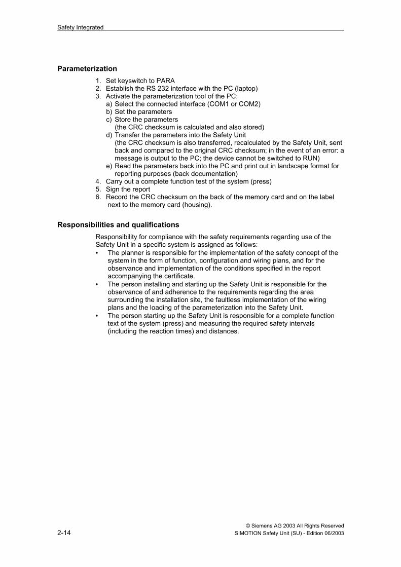
Power is supplied to the Safety Unit TM 121C by an external, electrically isolated power supply unit of 230 V AC/24 V DC, e.g. of the SITOP family. The primary side of SITOP power supply units resists surge voltage of symmetric ± 2 kV (conductor-conductor) and asymmetric ± 4 kV (conductor-ground). The 24 VDC signal inputs and outputs of the Safety Unit are designed for asymmetric surge voltages of up to ± 2 kV, so that the "Safety Unit with SITOP Power Supply" system features a high degree of surge immunity and meets the requirements of installation class 3 according to EN 61000-4-5 (see Fig. 2-1).
PE
Power supply units Safety Unit TM 121C
L1NPE
L+M X1
1 2 3 X51 2 3
PE
Surge voltage protection for installation class 3 as per EN 61000-4-5)
24V DC230V ACL1NPE
Fig. 2-2 Safety Unit power supply

Safety Integrated
© Siemens AG 2003 All Rights Reserved 2-20 SIMOTION Safety Unit (SU) - Edition 06/2003
Notes

© Siemens AG 2003 All Rights Reserved SIMOTION Safety Unit (SU) - Edition 06/2003 3-21
3 Description
Fig. 3-1 SIMOTION Safety Unit TM 121C
3.1 General information The safety system encompasses hardware, internal firmware routines such as short-circuit testing, and safety modules approved by the German trade association, e.g.: • Two-handed engaging • Foot switch • Operating mode selection • Safety guard monitoring • Engagement lockout • Safety door monitoring • EMERGENCY STOP • Motion monitor control • TDC switch-off • Valve/relay monitoring • Mechanical / hydraulical / bending function • Light curtain (ESPE)
3

Description
© Siemens AG 2003 All Rights Reserved3-22 SIMOTION Safety Unit (SU) - Edition 06/2003
3.2 FeaturesThe robust metal enclosure contains the processors, the power supply and theinputs and outputs. The processors have synchronous cycles and perform mutualchecks. States and results are compared to each other cyclically. In the event of adeviation, the system immediately enters a safe state.
The hardware of the Safety Unit features:• a two-channel, fail-safe press safety control system.• integrated electronic components instead of parts that are subject to wear and
tear such as relays and contactors.• compact control unit, small space requirements.• direct interfacing of all operating elements and feedback signals from the
press.
3.2.1 HardwareThe onboard I/O provides a basic configuration of inputs and outputs needed tomeet the safety requirements for presses.
The onboard I/O contains:• 24 V DC/5 V DC power supply with electrical isolation for internal logic circuit
with 2-channel overvoltage and undervoltage monitoring• 2-channel controller with mutual synchronization and data comparison• 12 safety-oriented digital inputs, 2-channel, that can also be connected via 1
channel if required:- max. 12 inputs SIL3 as per IEC 61508/Cat. 4 as per EN 954-1
or max. 24 inputs SIL2 or Cat. 1- type 2 as per DIN EN 61131-2
• extension option (additional printed circuit board): 4 safety-oriented digitalinputs, 2-channel, that can also be connected via 1 channel if required:- 4 inputs SIL3 as per IEC 61508/Cat. 4 as per EN 954-1
or 8 inputs SIL2 or Cat. 1- type 2 as per DIN EN 61131-2
• 2 digital counter inputs: 24 V, max. 500 Hz (e.g. for motion monitor)• 4 digital outputs, P/M-switching = 2 channel:
- SIL3 as per IEC 61508/Cat. 4 as per EN 954-1- rated current of 2 A as per DIN EN 61131-2
• 8 digital outputs, P - switching:- 4 outputs for sensor supply (short-circuit clocking)- 1 output for fault lamp (can be parameterized)- 3 outputs as reserve- rated current of 0.5 A as per DIN EN 61131-2
• keyswitch with three positions- PARA- STOP- RUN
• 2 LED displays:- green LED for RUN status- red LED for STOP status
• integrated display (for individual functions, see "Diagnosis"):- 4-digit 7-segment display for error messages

Description
© Siemens AG 2003 All Rights Reserved SIMOTION Safety Unit (SU) - Edition 06/2003 3-23
• plug-in memory card for configuration data (parameters) • RS 232 interface for parameterization/diagnosis and back documentation • 6 COMBICON connectors for power supply and I/O signals • 9-pin D-SUB connector for motion monitor
3.2.2 Operating states The following two operating states are signalized by two status LEDs:
Operating state RUN LED (green) STOP LED (red) INIT On (lit continuously) On (lit continuously) STOP Off Blinks at 2 Hz RUN On (lit continuously) Off PARA Blinks at 2 Hz On (lit continuously)
3.3 Interfaces
PARA
RUN
STOP
RUN
STOP
Keyswitch
Display
Mem
ory-
Car
d
X8 X9
111
1
X5
X63
8
X4
1 16
X3
1 16
X1
X2 1
1
3
8
LED
SIEMENS
SIMOTION Safety Unit
X1: 1L+, 1M (24 V DC) supply X2: Digital outputs 0.5 A X3: Digital inputs X4: Digital inputs X5: 2L+, 2M (24 V DC) supply X6: Digital outputs 2 A X8: RS232 X9: Frequency inputs (max. 500 Hz)
Fig. 3-2 Operating elements on front panel

Description
© Siemens AG 2003 All Rights Reserved 3-24 SIMOTION Safety Unit (SU) - Edition 06/2003
3.3.1 Connecting terminals
Table 3-1 Safety Unit connecting terminals Connector X1: Supply 1, 24V DC Term. Description X1.1 24V DC supply for power supply unit, sensor power supplies, signal output and binary inputs X1.2 0V (ground) X1.3 Ground terminal (enclosure/structure) Connector X2: Outputs 0.5 A, P-switching Term. Description Term. Description X2.1 Output (sensor power supply 1) X2.5 Output (sensor power supply 3) X2.2 Output (sensor power supply 2) X2.6 Output (sensor power supply 4) X2.3 Output (parameterizable) X2.7 Output (parameterizable) X2.4 Output (parameterizable) X2.8 Output (fault message)
Inputs (sensors) 1) Connector X4 Connector X3 Term. Description Sensor
power supply
Term. Description Sensor power supply
X4.1 Input X2.1 X3.1 Input X2.5 X4.2 Input X2.2 X3.2 Input X2.6 X4.3 Input X2.1 X3.3 Input X2.5 X4.4 Input X2.2 X3.4 Input X2.6 X4.5 Input X2.1 X3.5 Input X2.5 X4.6 Input X2.2 X3.6 Input X2.6 X4.7 Input X2.1 X3.7 Input X2.5 X4.8 Input X2.2 X3.8 Input X2.6 X4.9 Input X2.1 X3.9 Input X2.5 X4.10 Input X2.2 X3.10 Input X2.6 X4.11 Input X2.1 X3.11 Input X2.5 X4.12 Input X2.2 X3.12 Input X2.6 X4.13 Input (option) X2.1 X3.13 Input (option) X2.5 X4.14 Input (option) X2.2 X3.14 Input (option) X2.6 X4.15 Input (option) X2.1 X3.15 Input (option) X2.5 X4.16 Input (option) X2.2 X3.16 Input (option) X2.6
Connector X5: Supply 2, 24V DC Term. Description X5.1 24V DC supply for P/M-switching binary outputs, 2A X5.2 0V (ground) X5.3 Ground terminal (enclosure/structure) Connector X6: Outputs, 2A, 2-channel (actuators) P-switching M-switching Term. Description Term. Description X6.1 Output X6.2 Output X6.3 Output X6. 4 Output X6.5 Output X6.6 Output X6.7 Output X6.8 Output
1) Please note that for two-channel sensor inputs, the terminal numbers of both input channels must coincide: e.g. X3.1 and X4.1.
Description
© Siemens AG 2003 All Rights Reserved SIMOTION Safety Unit (SU) - Edition 06/2003 3-25
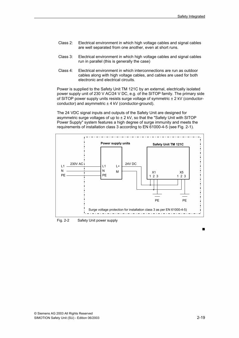
Table 3-2 Counter inputs Connector X9: Counter inputs, 9-pin SUB D connector (sockets) Pin Assignment 1 2 DI 1Z+, counter input/frequency input 1 3 DI 1Z- 4 5 6 7 DI 2Z+, counter input/frequency input 2 8 DI 2Z- 9
Use a shielded cable.
3.3.2 RS 232 interface Table 3-3: Pin assignment of SUB D connector, RS 232 Connector X8: 9-pin SUB D connector (sockets) Pin Assignment Faulty wiring Assignment Pin 1 1 2 Receive Data Receive Data 2 3 Transmit Data Transmit Data 3 4 4 5 Ground (0 V) Ground (0 V) 5 6 6 7 7 8 8 9
9 Safety Unit PC/Laptop
Use a shielded cable.
Description
© Siemens AG 2003 All Rights Reserved 3-26 SIMOTION Safety Unit (SU) - Edition 06/2003
Notes

© Siemens AG 2003 All Rights Reserved SIMOTION Safety Unit (SU) - Edition 06/2003 4-27
4 Mounting and Cabling
4.1 Mounting The Safety Unit is mounted on the control cabinet panel with 4 screws.
52.5 260
120
135.
514
4.5
365
PARASTOP
RUNRUNSTOP
SIMOTION Safety Unit
SIEMENS
Fig. 4-1 Dimensions as viewed from the front
Attention To ground the enclosure, ensure that there is a conductive interface between the switching cabinet and the Safety Unit. For this purpose, mount the enclosure with toothed washers.
4

Mounting and Cabling
© Siemens AG 2003 All Rights Reserved 4-28 SIMOTION Safety Unit (SU) - Edition 06/2003
104.5112.65
7812
0
144.
5
Fig. 4-2 Dimensions as viewed from the side
4.2 Cabling
Introduction In this chapter, we will show you what you need to pay special attention to as you connect the Safety Unit. At the very least, these basic rules must be adhered to in order to ensure faultless operation of the Safety Unit.
Cables You can use flexible cables with the cross sections specified in the data sheet. A cable lug is not required. Table 4-1 Cabling rules for the Safety Unit Cabling rules for ... Safety Unit Connectable cable cross sections for solid cables
No
Without cable lug 0.25 to 0.75 mm2 Connectable cable cross sections for flexible cables
With cable lug 0.25 to 0.75 mm2 Voltage supply: 0.75 to 1.5 mm2

Mounting and Cabling
© Siemens AG 2003 All Rights Reserved SIMOTION Safety Unit (SU) - Edition 06/2003 4-29
Specific applications When connecting the system, please note the safety and accident prevention regulations that apply to the specific application, e.g. Safety of Machinery regulations.
EMERGENCY STOP systems EMERGENCY STOP systems in accordance with IEC 204 must be connected in such a way that they remain effective in all operating modes.
120/230 V AC supply of the power supply unit The table below shows the points you should watch out for when connecting the external power supply (e.g. SITOP) to a 120/230 V AC line. For... ...ensure that... Buildings suitable external lightning protection devices are in
place. AC supply lines of the power supply unit
suitable external and internal lightning protection devices are in place.
Permanently installed systems without all-pole mains switch
there is a line disconnector (switch) in the installation.
Power supply units for supplying the Safety Unit with 24 V DC
the set rated voltage range corresponds to the local line voltage.
Residual current-operated protective device
the F1 circuit breaker is suitable for the sum of the leakage currents of the system.
24 V DC supply of Safety Unit The table below shows the points you should watch out for when connecting the Safety Unit to the 24 V DC supply. For... ...ensure that... 24 V DC supplies the supply voltage is generated as a reliably electrically
isolated extra-low voltage. 24 V DC signal lines suitable external and internal lightning protection
devices are in place.
Protection against external electrical influences The following table lists the points that require special attention in order to protect the system against electrical influences or faults. For... ...ensure that... All units or systems in which the Safety Unit is installed
the unit and system components are properly connected to protective ground to enable the leakage of electromagnetic disturbances.
Connection and signal lines all lines are correctly laid and connected. Signal lines a breakage in a signal line does not put the system in
an undefined state.

Mounting and Cabling
© Siemens AG 2003 All Rights Reserved 4-30 SIMOTION Safety Unit (SU) - Edition 06/2003
Notes

© Siemens AG 2003 All Rights ReservedSIMOTION Safety Unit (SU) - Edition 06/2003 5-31
5 Parameterization and Diagnosis
5.1 Parameterization
5.1.1 General information
PrerequisitesThe Safety Unit is parameterized using a parameterization tool. The tool is includedon the CD of the software package that can be ordered (see "Accessories") andhas to be installed on your PC. The tool requires approx. 5 MB of hard disk space.
Your PC/laptop must meet the following minimum requirements:
Interface COM1 or COM2Processor 233 MHzRAM 64 MBOperating system Windows NT 4.0
Windows 2000Windows XPOther operating systems upon request
ProcedureWhen loading, the parameters are transferred into the Safety Unit from the PC andstored there. The basic procedure is described in 2.2.
5.1.2 Setting parameters with the "Parameterization tool"
Operating instructions• Terminal assignments and time settings are stored by activating the "Accept"
button.• To delete the terminal assignments or time settings that have been made,
activate the "Accept" button with the input box empty.• The associated functions are not enabled until you have specified the terminal
number.• When you assign the terminals, the parameterization tool makes you aware of
duplicate assignments or incorrect inputs.• Whenever the parameter setting is made using radio buttons, only one setting
can be activated.
A brief description of the parameterization tool menus follows.
5
Parameterization and Diagnosis
© Siemens AG 2003 All Rights Reserved5-32 SIMOTION Safety Unit (SU) - Edition 06/2003
Press typeSelect Mechanical press/Hydraulic press/Press brake to make a preselection andto activate the Mechanical/Hydraulic/Bending function.
Operating modesAssign a terminal to each required operating mode.• Operating mode 1 is always "Set up"• Operating modes 2 to 6 (single stroke/continuous
stroke/changeover/continuous stroke, automatic/single stroke, ESPE) arefreely selectable.
Safety functions• EMERGENCY STOP (max. 4 with, max. 4 without reclosing lockout)
- Define the terminal pair- Enter the discrepancy time- Deactivate the function for the required operating modes
• Safety guards (max. 4 with, max. 4 without reclosing lockout)- Same procedure as for EMERGENCY STOP.
• Safety gates (max. 3 with, max. 3 without acknowledgement)- Define the terminal pair- Deactivate the function for the required operating modes- For safety gate with acknowledgement, define the terminal for the
acknowledge button• Engagement lockout (max. 2)
- Same procedure as for EMERGENCY STOP.
Operation• Acknowledge button (for error messages and restart lockout)
- Define the terminal• Two-hand (max. 3 operator panels)
- Define the terminal pairs for the NC and NO contacts.- If it is to be possible to switch off the operator panel, select the terminal
and assign the NC or NO contact element.- Deactivate the function for the required operating modes.
• Foot switch (max. 3 foot switches)- Define the terminal for the NC and NO contacts.- If it is to be possible to switch off the foot switch, select the terminal and
assign the NC or NO contact.- Deactivate the function for the required operating modes.
• Light curtainTo be able to activate the function, "Single stroke EPSE" must be selected asthe operating mode.- Define the terminal pair- Enter the discrepancy time- Deactivate the function for the required operating modes- Define the terminals for the operating mode selector switch, single
break/double break.- Define either the "Standard Mode" or "Schweden Mode".- Define the acknowledgement of the restart lockout:
either via previously activated two-hand operation/foot switch or via abutton (if acknowledgement takes place via a button, define the terminal).
- Select whether or not it should be possible to switch off the safetyoperation (if it can be switched off, define the terminal).

Parameterization and Diagnosis
© Siemens AG 2003 All Rights ReservedSIMOTION Safety Unit (SU) - Edition 06/2003 5-33
Forming enables (example for mechanical press)Under "Forming enables", you can set whether certain signals that are required forstarting/stopping and operating the press are predefined or whether they are readin through an input (terminal). The following settings must be specified for eachparameterized operating mode:• Start condition (must have state "1" at start)
- Set the start condition permanently to signal "1"- Read in the start condition at a terminal and define the terminal.
• Only for continuous stroke operating modes! Continuous stroke"Immediate STOP" (must have state "0" when stopped)- Set the continuous stroke STOP permanently to signal "1" (no stop!)- Read in at a terminal and define the terminal
• Only for continuous stroke operating modes! Continuous stroke "STOP inTDC" (must have state "0" when stopped)- Set the continuous stroke STOP in TDC permanently to signal "1" (no
stop!) or- Read in at a terminal and define the terminal
• Only for single stroke operating modes! Acceptance of START command- No acceptance indicates inching operation- Acceptance with run-up cam or acceptance point- Read in acceptance at the input and define the terminal
• Safe movement (safety devices not operative with "1" signal)- Connect safe movement to "0" (safety devices always operative)- Read in safe movement via the input (action of safety devices can be
switched off via input) and define the terminal• Not for single stroke ESPE! Start enable
- Enabling of the operator panel/foot switch (start the press using two-hand/foot)
- Read in the enable via the input (external start) and define the terminal• External safety device 1/2 ("0" signal shuts off the valve outputs)
- Connect the input to signal "1" (safety device not active)- Read in via a terminal (connect the safety device to one-channel input) and
define the terminal
NoteFor information on the individual functions of Mechanical/Hydraulics/Bendingsee the "Application manual", Edition 06.2003 (contained on the CD-ROM of thesoftware package).

Parameterization and Diagnosis
© Siemens AG 2003 All Rights Reserved 5-34 SIMOTION Safety Unit (SU) - Edition 06/2003
5.2 Diagnosis The Safety Unit monitors all incoming and outgoing signals. Error messages are • shown on the display, • indicated by a fault lamp and • can be read out via the RS 232 interface of your PC. The diagnosis can be performed in all operating states (diagnosis may not be possible in the event of a HW fault).
5.2.1 Diagnosis using display The 4-digit display shows error messages or operating states. If the system is functioning properly, the Safety Unit display shows the current operating state. To indicate an error, the first place (F) blinks at 2 Hz. Since several errors may occur simultaneously, it makes sense to read out the diagnosis buffer (see Chap. 5.2.3).
5.2.2 Diagnosis using pilot lamp The connected fault pilot lamp can indicate the following conditions: Signal output Condition Indication
INIT/PARA/STOP Lights up permanently
Errors requiring acknowledgement or self-acknowledging errors
Blinks at 2 Hz
Connector X2.8
Fault-free operation in RUN Off
5.2.3 Reading out diagnosis messages All of the error information is contained in the diagnosis buffer, which can be read out through the RS 232 interface using the parameterization tool. The following diagnosis data can be called up:
System data The parameterization tool reads out the following system data: • Firmware status: version and date • Current operating state: PARA, STOP or RUN • Position of keyswitch: PARA, STOP or RUN • Signature for CRC "EPROM1" (program memory) • Signature for CRC "EPROM2" (program memory) • Signature for CRC "MEMORY CARD" (program memory) • User operating mode 1 ... 6 that was last selected • Cycle times of the last 10 RUN cycles in ms
Parameterization and Diagnosis
© Siemens AG 2003 All Rights ReservedSIMOTION Safety Unit (SU) - Edition 06/2003 5-35
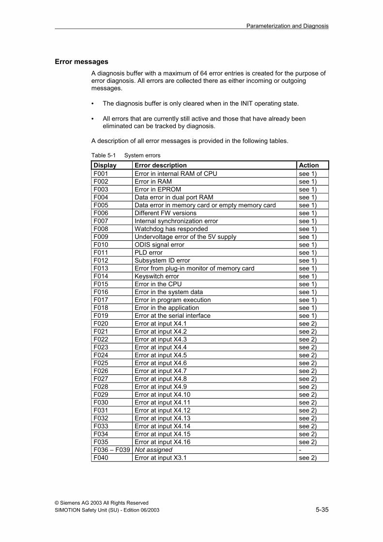
Error messagesA diagnosis buffer with a maximum of 64 error entries is created for the purpose oferror diagnosis. All errors are collected there as either incoming or outgoingmessages.
• The diagnosis buffer is only cleared when in the INIT operating state.
• All errors that are currently still active and those that have already beeneliminated can be tracked by diagnosis.
A description of all error messages is provided in the following tables.
Table 5-1 System errors
Display Error description ActionF001 Error in internal RAM of CPU see 1)F002 Error in RAM see 1)F003 Error in EPROM see 1)F004 Data error in dual port RAM see 1)F005 Data error in memory card or empty memory card see 1)F006 Different FW versions see 1)F007 Internal synchronization error see 1)F008 Watchdog has responded see 1)F009 Undervoltage error of the 5V supply see 1)F010 ODIS signal error see 1)F011 PLD error see 1)F012 Subsystem ID error see 1)F013 Error from plug-in monitor of memory card see 1)F014 Keyswitch error see 1)F015 Error in the CPU see 1)F016 Error in the system data see 1)F017 Error in program execution see 1)F018 Error in the application see 1)F019 Error at the serial interface see 1)F020 Error at input X4.1 see 2)F021 Error at input X4.2 see 2)F022 Error at input X4.3 see 2)F023 Error at input X4.4 see 2)F024 Error at input X4.5 see 2)F025 Error at input X4.6 see 2)F026 Error at input X4.7 see 2)F027 Error at input X4.8 see 2)F028 Error at input X4.9 see 2)F029 Error at input X4.10 see 2)F030 Error at input X4.11 see 2)F031 Error at input X4.12 see 2)F032 Error at input X4.13 see 2)F033 Error at input X4.14 see 2)F034 Error at input X4.15 see 2)F035 Error at input X4.16 see 2)F036 – F039 Not assigned -F040 Error at input X3.1 see 2)
Parameterization and Diagnosis
© Siemens AG 2003 All Rights Reserved5-36 SIMOTION Safety Unit (SU) - Edition 06/2003
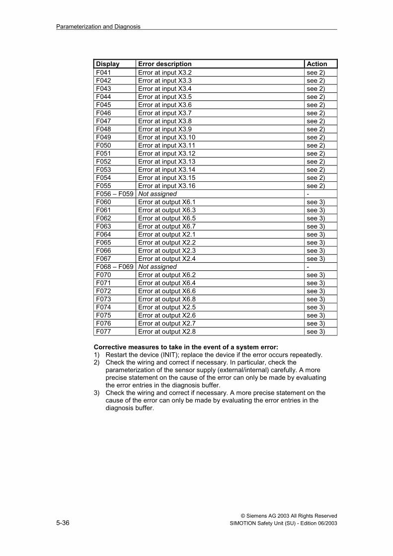
Display Error description ActionF041 Error at input X3.2 see 2)F042 Error at input X3.3 see 2)F043 Error at input X3.4 see 2)F044 Error at input X3.5 see 2)F045 Error at input X3.6 see 2)F046 Error at input X3.7 see 2)F047 Error at input X3.8 see 2)F048 Error at input X3.9 see 2)F049 Error at input X3.10 see 2)F050 Error at input X3.11 see 2)F051 Error at input X3.12 see 2)F052 Error at input X3.13 see 2)F053 Error at input X3.14 see 2)F054 Error at input X3.15 see 2)F055 Error at input X3.16 see 2)F056 – F059 Not assigned -F060 Error at output X6.1 see 3)F061 Error at output X6.3 see 3)F062 Error at output X6.5 see 3)F063 Error at output X6.7 see 3)F064 Error at output X2.1 see 3)F065 Error at output X2.2 see 3)F066 Error at output X2.3 see 3)F067 Error at output X2.4 see 3)F068 – F069 Not assigned -F070 Error at output X6.2 see 3)F071 Error at output X6.4 see 3)F072 Error at output X6.6 see 3)F073 Error at output X6.8 see 3)F074 Error at output X2.5 see 3)F075 Error at output X2.6 see 3)F076 Error at output X2.7 see 3)F077 Error at output X2.8 see 3)
Corrective measures to take in the event of a system error:1) Restart the device (INIT); replace the device if the error occurs repeatedly.2) Check the wiring and correct if necessary. In particular, check the
parameterization of the sensor supply (external/internal) carefully. A moreprecise statement on the cause of the error can only be made by evaluatingthe error entries in the diagnosis buffer.
3) Check the wiring and correct if necessary. A more precise statement on thecause of the error can only be made by evaluating the error entries in thediagnosis buffer.

Parameterization and Diagnosis
© Siemens AG 2003 All Rights ReservedSIMOTION Safety Unit (SU) - Edition 06/2003 5-37
Table 5-2 Error messages requiring acknowledgement
Display Error descriptionF101 Overtravel cam, static "1"F102 Overtravel cam failureF103 Overtravel cam, static "0"F104 Overtravel distance too longF105 Run-up cam failureF106 Change in operating mode not in TDCF107 Short circuit at operating mode selector switchF108 Motion monitorF109 Run-time error, channel 1 (valve 1)F110 Run-time error, channel 2 (valve 2)F111 Run-time error, channel 3 (valve 3)F112 Run-time error, channel 4 (EMERGENCY STOP relaying)F113 Operating mode selection, light curtain (single break/double break)F114 Short circuit or "0" at operating mode selector switch, light curtainF115 Setting - dynamic camF122 Discrepancy error, acceptance pointF123 Error, dynamic valve control, channel 1F124 Error, dynamic valve control, channel 2F125 Error, dynamic valve control, channel 3F316 Restart lockout set for EMERGENCY STOPF317 Restart lockout set for safety guardF318 Restart lockout set for light curtainF319 Restart lockout EMERGENCY STOP relayingF320 *) Safety gate closed, not ready for acknowledgement (blocking)F321 *) Safety gate closed, ready for acknowledgement
This error can only be acknowledged in the setup mode*) If the safety gate display is parameterized via the fault lamp.

Parameterization and Diagnosis
© Siemens AG 2003 All Rights Reserved5-38 SIMOTION Safety Unit (SU) - Edition 06/2003
Table 5-3 Self-acknowledging error messages
Display Error descriptionF201 Discrepancy error, EMERGENCY_STOP 1F202 Discrepancy error, EMERGENCY_STOP 2F203 Discrepancy error, EMERGENCY_STOP 3F204 Discrepancy error, EMERGENCY_STOP 4F205 Discrepancy error, EMERGENCY_STOP 5F206 Discrepancy error, EMERGENCY_STOP 6F207 Discrepancy error, EMERGENCY_STOP 7F208 Discrepancy error, EMERGENCY_STOP 8F209 Discrepancy error, safety guard 1F210 Discrepancy error, safety guard 2F211 Discrepancy error, safety guard 3F212 Discrepancy error, safety guard 4F213 Discrepancy error, safety guard 5F214 Discrepancy error, safety guard 6F215 Discrepancy error, safety guard 7F216 Discrepancy error, safety guard 8F217 Contact error, two-hand 1F218 Contact error, two-hand 2F219 Contact error, two-hand 3F220-F222 Not assignedF223 Discrepancy error, engagement lockout 1F224 Discrepancy error, engagement lockout 2F225 Discrepancy error, light curtainF226 Contact error, foot switch 1F227 Contact error, foot switch 2F228 Contact error, foot switch 3F229 Discrepancy error, access protection 1F230 Discrepancy error, access protection 2F231 Contact monitor, two-hand 1F232 Contact monitor, two-hand 2F233 Contact monitor, two-hand 3F234 Contact monitor, foot 1F235 Contact monitor, foot 2F236 Contact monitor, foot 3F237 Operating error (two-hand 1 was activated but is not active)F238 Operating error (two-hand 2 was activated but is not active)F239 Operating error (two-hand 3 was activated but is not active)F240 Operating error (foot 1 was activated but is not active)F241 Operating error (foot 2 was activated but is not active)F242 Operating error (foot 3 was activated but is not active)

© Siemens AG 2003 All Rights ReservedSIMOTION Safety Unit (SU) - Edition 06/2003 6-39
6 Technical Data
6.1 Standards and certifications
IntroductionIn this section you will find the most important standards and certifications withwhich the Safety Unit must comply. The current status and the current version ofthe standards, as well as the current editions, are contained in the report to theBG*) certificate.
DIN EN 61131-2The Safety Unit meets the requirements and criteria of the DIN EN 61131Standard, Part 2 (2001).
CE markingOur products meet the requirements and protective targets of the following ECdirectives and correspond to the harmonized European Standards (EN) that werepublished for programmable logic controllers in the Official Journal of the EuropeanCommunity:• 89/336/EEC "Electromagnetic Compatibility" (EMC Directive)• 73/23/EEC "Electrical Equipment for Use Within Specific Voltage Limits" (Low
Voltage Equipment Directive)The EC Declarations of Conformity are made available online by the competentauthorities.
Area of applicationThe Safety Unit is designed for use in the industrial environment.
Requirements regardingArea of applicationEmission Interference
immunityIndustry EN 61000-6-4: 2001 EN 61000-6-2: 2001
CULUS certificationUL 508, CAN/CSA C22.2 No. 14-95
BG∗∗∗∗ ) certificateThe current report to the BG certificate is available from your local sales office.
∗ ) Berufsgenossenschaft = German trade association
6

Technical Data
© Siemens AG 2003 All Rights Reserved6-40 SIMOTION Safety Unit (SU) - Edition 06/2003
6.2 Safety extra low voltage
Safety extra low voltage
! WarningThe Safety Unit must be operated with a safety extra low voltage (SELV). Thismeans that, even in the event of a malfunction, the maximum voltage that mayact on this module must not exceed 60 V DC .
Additional information on safety extra low voltages may be found in the datasheets of the power supplies in use.
All system components that are capable of supplying electrical energy in one formor another must comply with these conditions. Each additional circuit (24 V DC)used in the system must feature a safety extra low voltage. Please refer to therespective data sheets or consult the manufacturer.
Please note also that it is possible to connect encoders and actuators with anexternal power supply to the Safety Unit. Ensure that the safety extra low voltage iscomplied with for these devices. The process signal of a 24 V digital module maynot exceed a fault voltage of 60 V DC in the event of a malfunction.
Requirements regarding power supplies
NoteOnly use power supply units/power packs (230 V AC --> 24 V DC) with a voltagebreakdown buffer time of at least 20 ms. We offer 1-phase industrial standardpower supplies 24 V (order no. 6EP1334-2AA00 and 6EP1333-2AA00) of theSITOP device series.
Additional information is found on our homepage:http://www.ad.siemens.de/sitop/index.shtml
• Technical details are found under "Support".• You can place orders under "E-Commerce".
6.3 Electromagnetic compatibility
DefinitionThe electromagnetic compatibility is the ability of an electrical system to operatesatisfactorily in its electromagnetic environment without having an influence on thisenvironment.
The Safety Unit is in compliance with the requirements of the EMC law of theEuropean domestic market.
Below you will find information on interference immunity and RFI suppression.

Technical Data
© Siemens AG 2003 All Rights ReservedSIMOTION Safety Unit (SU) - Edition 06/2003 6-41
Requirements regarding emissionTable 6-1 EmissionRequirements In accordance with EN
61000-6-4Device group 1 as per EN 55011Class A as per EN 55011
Pulsed transientsThe following table presents the electromagnetic compatibility of the Safety Unitwith respect to pulsed transients.
Table 6-2 Pulsed transientsPulsed transients Tested with Corresponds
to severitylevel
Electrostatic discharge as perEN 61000-4-2
15 kV contact discharge8 kV air discharge
44
Burst as per EN 61000-4-4 2 kV, power supply lines 24 V DC2 kV, I/O lines4 kV, power supply lines 230 V AC
(SITOP power supply)
344
Surge as per EN 61000-4-5Cable/cable (symmetric) 0.5 kV, power supply lines 24 V DC
2 kV, power supply lines 230 V AC(SITOP power supply)
13
Line/ground (asymmetric) 0.5 kV, power supply lines 24 V DC4 kV, power supply lines 230 V AC
(SITOP power supply)2 kV, I/O lines
14
3
Sinusoidal transientsDevice in radiated RF field as per IEC 61000-4-3:• Electromagnetic RF field, amplitude-modulated
- from 80 to 1000 MHz- 10 V/m; severity level 3- 80 % AM (1 kHz)
• Electromagnetic RF field, pulse-modulated (mobile phone range)- 800 to 960 MHz and 1.4 to 2.06 GHz- 30 V/m; severity level X- 50 % ESD- 200 Hz repetition frequency
• RF disturbances on signal and data lines, etc., as per IEC 61000-4-6, highfrequency, asymmetric, amplitude-modulated- from 0.15 to 80 MHz- 10 V RMS, unmodulated; severity level 3- 80 % AM (1 kHz)- 150 Ω source impedance

Technical Data
© Siemens AG 2003 All Rights Reserved6-42 SIMOTION Safety Unit (SU) - Edition 06/2003
6.4 Mechanical and climatic ambient conditions
6.4.1 Transport and storageThe Safety Unit exceeds the requirements of the DIN EN 61131, Part 2, withregard to transport and storage conditions. The following specifications apply totransport and storage in the original packaging.
Type of condition Allowable rangeFree fall (with packaging) ≤ 75 cmTemperature - 40 °C ... + 70 °CAir pressure 1080 ... 660 hPa
(corresponds to an altitude of -1000 ...3500 m)
Relative humidity From 5 to 95 %, without condensation
6.4.2 Operation
Operating conditionsThe Safety Unit is designed for use in a weather-protected, stationary installation.The operating conditions exceed the requirements as per DIN EN 61131-2.
The Safety Unit is in compliance with the operating conditions of Class 3C3 as perDIN EN 60721-3-3 (installation in locations with a high traffic density and in theimmediate vicinity of industrial plants with chemical emissions).
LimitationsThe Safety Unit may not be used without the implementation of supplementarymeasures:• in locations with a high degree of ionizing radiation.• in locations with severe operating conditions, e.g.
- due to dust formation,- corrosive vapors or gasses.
• in systems that require special monitoring, such as electrical systems inespecially hazardous areas.
Mechanical ambient conditionsThe mechanical ambient conditions for the Safety Unit are listed in the following table(the values describe sinusoidal vibrations):
Frequency range (Hz) Continuous Occasional10 ≤ f ≤ 58 0.075 mm amplitude 0.15 mm amplitude58 ≤ f ≤ 200 1 g constant acceleration 1) 2 g constant
acceleration 1)
1) Gravitational acceleration g equals approx. 9.81 m/s2
Technical Data
© Siemens AG 2003 All Rights ReservedSIMOTION Safety Unit (SU) - Edition 06/2003 6-43
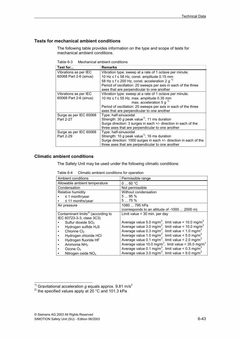
Tests for mechanical ambient conditionsThe following table provides information on the type and scope of tests formechanical ambient conditions.
Table 6-3 Mechanical ambient conditionsTest for... RemarksVibrations as per IEC60068 Part 2-6 (sinus)
Vibration type: sweep at a rate of 1 octave per minute.10 Hz ≤ f ≤ 58 Hz, const. amplitude 0.15 mm58 Hz ≤ f ≤ 200 Hz, const. acceleration 2 g 1)
Period of oscillation: 20 sweeps per axis in each of the threeaxes that are perpendicular to one another
Vibrations as per IEC60068 Part 2-6 (sinus)
Vibration type: sweep at a rate of 1 octave per minute.10 Hz ≤ f ≤ 55 Hz, max. amplitude 0.35 mm
max. acceleration 5 g 1)
Period of oscillation: 20 sweeps per axis in each of the threeaxes that are perpendicular to one another
Surge as per IEC 60068Part 2-27
Type: half-sinusoidalStrength: 30 g peak value1), 11 ms durationSurge direction: 3 surges in each +/- direction in each of thethree axes that are perpendicular to one another
Surge as per IEC 60068Part 2-29
Type: half-sinusoidalStrength: 10 g peak value1), 16 ms durationSurge direction: 1000 surges in each +/- direction in each of thethree axes that are perpendicular to one another
Climatic ambient conditionsThe Safety Unit may be used under the following climatic conditions:
Table 6-4 Climatic ambient conditions for operationAmbient conditions Permissible rangeAllowable ambient temperature 0 ... 60 °CCondensation Not permissibleRelative humidity• ≤ 1 month/year• ≤ 11 months/year
Without condensation5 ... 95 %5 ... 75 %
Air pressure 1080 ... 795 hPa(corresponds to an altitude of -1000 ... 2000 m)
Contaminant limits2) (according toIEC 60723-3-3, class 3C3)
Limit value < 30 min. per day
• Sulfur dioxide SO2 Average value 5.0 mg/m3, limit value < 10.0 mg/m3
• Hydrogen sulfide H2S Average value 3.0 mg/m3, limit value < 10.0 mg/m3
• Chlorine Cl2 Average value 0.3 mg/m3, limit value < 1.0 mg/m3
• Hydrogen chloride HCl Average value 1.0 mg/m3, limit value < 5.0 mg/m3
• Hydrogen fluoride HF Average value 0.1 mg/m3, limit value < 2.0 mg/m3
• Ammonia NH3 Average value 10.0 mg/m3, limit value < 35.0 mg/m3
• Ozone O3 Average value 0.1 mg/m3, limit value < 0.3 mg/m3
• Nitrogen oxide NOx Average value 3.0 mg/m3, limit value < 9.0 mg/m3
1) Gravitational acceleration g equals approx. 9.81 m/s2
2) the specified values apply at 20 °C and 101.3 kPa

Technical Data
© Siemens AG 2003 All Rights Reserved6-44 SIMOTION Safety Unit (SU) - Edition 06/2003
6.5 Technical data
Function and area of applicationFunction Parameterizable compact safety minicontroller.Area of Application Fail-safe applications as per EN 951 and IEC 61508.Technology Two-channel control unit with data comparison and
automatic check in the 1oo2 architecture as per IEC61508, i.e. each partial controller can initiate the safetyfunction.
Pilot application Safety-related part of mechanical presses (EN 692) andhydraulic presses (EN 693)
Dimensions and weightDimensions H x W x D 125 mm x 365 mm x 115 mmWeight 1.7 kg
Protection and safety requirementsAs per EC directive 98/37/EC for machines and low voltage directive 72/23/EECDegree of protection as per EN 60529 IP 20 (protection against contact
with standard probes)Protection class as per IEC 60536(VDE 0106-1)
I (protective ground connectionusing toothed screws is required)
Maximum classification in fail-safe operation• As per IEC 61508 (Safety Integrity
Level)• As per EN 954 (Category)
SIL 3Cat. 4
Protection against foreign bodies and water protectionProtection against...
Remark
Contact Degree of protection IP 20 as per EN 60529 with standardprobes
Foreign bodies With diameters over 6 mmWater No special protection
Specific dataAllowable ambient temperature 0 °C to +60 °CCondensation Not permissibleAllowable cable length for 24 V supply Max. 10 mAllowable cable length for I/O signals• Unshielded• Shielded
Max. 50 mMax.100 m (counter input max. 50 m)
Recommended cable cross sections (flex.)• Voltage supply, connector X1 or X5• Digital inputs, connector X3 or X4• Digital outputs 0.5A, connector X2• Digital outputs 2A, connector X6
0.75 to 1.5 mm2 (≈AWG 18 to 16)0.25 to 0.75 mm2 (≈AWG 22 to 18)0.25 to 0.75 mm2 (≈AWG 22 to 18)0.75 mm2 (≈AWG 18)

Technical Data
© Siemens AG 2003 All Rights ReservedSIMOTION Safety Unit (SU) - Edition 06/2003 6-45
Digital inputsQuantity System 1 System 2Standard digital inputs• Basic device• Extension options
12 (X4.1 to X4.12)4 (X4.13 to X4.16)
12 (X3.1 to X3.12)4 (X3.13 to X3.16)
Differential/counter inputs 1 (X9.2 and X9.3) 1 (X9.7 and X9.8)Input voltage as per EN 1131-2Type 2• Rated value• Signal "0"• Signal "1"
24 V DC-30V ... 5V11V ... 30V
Input current at signal "1" Typ. 8 mAConnection of 2-wire proximityswitch• Allowable residual current
Possible (passive encoder clock)Max. 2 mA
Digital outputs 0.5 A, P-switchingQuantity System 1 System 2Sensor power supplies 2 (X2.1 and X2.2) 2 (X2.5 and X2.6)Reserve (can be parameterized) 1 (X2.3) 1 (X2.7)Pilot lamp, fault — 1 (X2.8)Reserve (can be parameterized) 1 (X2.4) —Voltage drop at signal "1" Max. 1.5 V at 0.5 AOutput current at signal "1"• Rated value as per EN 1131-2• Allowable range
0.5 A0 ... 0. 6 A
Load resistance at 1L+ = 28.8 V ≥ 48 ΩAllowable sum current 3.2 AResidual current at signal "0" Max. 0.1 mAShort circuit and overload protection Electronic
Digital outputs 2 A, P/M-switchingSystem 1/P-driver System 2/M-driver
Quantity 4 (X6.1/3/5/7) 4 (X6.2/4/6/8)Voltage drop at signal "1" Max. 1.0 V at 2 A Max. 0.5 V at 2 AOutput current at signal "1"• Rated value as per EN 1131-2• Allowable range
2 A7 mA ... 2.4 A
Load resistance range• 2L+ = 20.4 V• 2L+ = 28.8 V
≤ 2.7 kΩ≥ 12 Ω
Allowable sum current 6.4 AResidual current at signal "0" Max. 0.5 mA —Conductor breakage detection Electronic —Monitoring of supply voltage Electronic —Short circuit and overloadprotection
Electronic

Technical Data
© Siemens AG 2003 All Rights Reserved6-46 SIMOTION Safety Unit (SU) - Edition 06/2003
Voltages, potentialsRated voltage (1L+, 2L+) 24 V DC (X1.1, X5.1)Reference potential (1M, 2M) 0 V DC (X1.2, X5.2)Protective ground connection (1, 2) Ground (X1.3, X5.3)Allowable range 1L+, 2L+ (average value) 20.4 V ... 28.8 VVoltage loss ride-through• 1L+, 2L+, digital outputs• Int. 5 V supply
No≥ 5 ms (ext. 24 V power supply unit≥ 20 ms)
Electrical isolation• Between 1L+, 2L+ and int. 5 V• Between the inputs/outputs and bus• Test voltage• Rated insulation voltage
YesVia optocoupler500 V AC50 V AC
Power lossIdle without inputs and outputs (RUN) Typ. 10 WPower loss of inputs at signal "1" Typ. 0.2 W / inputPower loss of outputs• Digital outputs, 0.5 A, P-switching• Digital outputs, 2 A, P/M-switching
Typ. 0.9 W / outputTyp. 0.8 W / output
Current consumptionFrom 1L+, 24 V (RUN operating state)• Without load• At 3 A sum current of the 0.5 A outputs
Fault-free operationMax. 0.5 AMax. 3.5 A
Current consumption from 2L+, 24 V• Without load• At 6 A sum current of the 2 A outputs
Fault-free operationMax. 0.1 AMax. 6.1 A

Technical Data
© Siemens AG 2003 All Rights ReservedSIMOTION Safety Unit (SU) - Edition 06/2003 6-47
Time, frequencySystem error detection time• Selftests CPU, RAM, EPROM, memory
card (INIT/STOP/RUN/PARA)• DI selftests (standstill and upward
movement in RUN; 36 test steps)Required number of strokes for one testrun (mech. press) with– 80 strokes/min → 1; rounded– 160 strokes/min → 2; rounded– 200 strokes/min → 3; rounded
• DO selftests (standstill and upwardmovement in RUN; 12 test steps)Required number of strokes for one testrun (mech. press) with– 200 strokes/min → 1; rounded
≤ 2 min
360 ms (cycle time 10 ms)
120 ms (cycle time 10 ms)
System error response time(time from system error recognition to shutoffof outputs)
≤ 1ms
Cycle time 1) Typ. 7 ms (downward movement,otherwise typ. 10 ms)
Reaction time input/output1)
incl. HW delays(without switching times of sensors/actuators)
Max. 16 ms (downwardmovement, otherwise max.20 ms)
Input delay• Standard digital inputs• Differential/counter inputs
1.7 ... 2.7 ms0.5 ... 0.9 ms
Differential/counter inputs• Minimum pulse duration• Maximum frequency
1 ms500 Hz
Output delay forRLoad ≤ 1 kΩ; CLoad ≤ 10 nF
Max. 0.3 ms
Switching frequency of outputs• For ohmic load• For inductive load (IEC 947-5-1, DC 13)• For lamp load
Max. 30 HzMax. 2 HzMax. 10 Hz
Test pulse, sensor clock (obscuration time) 4 ... 6 msTest pulse, digital outputs(illumination/obscuration times)
≤ 1ms
Data for selection of an actuatorRated voltage 24 V DCPickup voltage/switch-on voltage ≤ 16.8 V (70 % x UN)Drop-out voltage/switch-off voltage ≥ 2.4 V (10 % x UN)Pickup/switch-on time for active output test ≥ 1.1 msDrop-out/switch-off time for active output test ≥ 1.1 ms
1) The times are dependent on the parameterization; they were measured with the following
parameterization: Mechanical press in continuous stroke operating mode with one-manoperation and 1 two-hand, 1 foot switch, 1 safety guard, 1 safety gate, 1 EMERGENCYSTOP, 1 ESPE.

Technical Data
© Siemens AG 2003 All Rights Reserved6-48 SIMOTION Safety Unit (SU) - Edition 06/2003
Status, diagnosisStatus displays• Status display, RUN (operation)• Status display, STOP
Green LEDRed LED
Error display Via displayDiagnosis information can be called up Via RS 232 interface

© Siemens AG 2003 All Rights ReservedSIMOTION Safety Unit (SU) - Edition 06/2003 A-49
A Accessories, Order Numbers
A.1 Spare partsItem Order no. CommentSafety Unit 6AU1121-2CA00-0AA0 24 digital inputsSafety Unit with option 6AU1121-3CA00-0AA0 32 digital inputsMemory card 6AU1712-1MA00-0AA0 128 kByte
A.2 AccessoriesItem Order no. CommentSoftware packageV2.0
6AU1810-0XA20-0XA0 Contains:• CD-ROM
(parameterization tool +manual)
• Link cable5 connector sets 6AU1712-1CB00-0AA0 With 4 connectors each
A

Accessories, Order Numbers
© Siemens AG 2003 All Rights ReservedA-50 SIMOTION Safety Unit (SU) - Edition 06/2003
Notes

© Siemens AG 2003 All Rights ReservedSIMOTION Safety Unit (SU) - Edition 06/2003 B-51
B Glossary
1v1 evaluationType of encoder evaluation - In 1v1 evaluation, there is one encoder and it isconnected to the module via 1 channel.
2v2 evaluationType of encoder evaluation - In 2v2 evaluation, the inputs are internally comparedwith regard to their signal states (equivalence or non-equivalence).
see: Discrepancy analysis
A
ACKAcknowledgement message.
ActuatorActuators are, for example, power relays or contactors for switching on loadequipment, or they are the load equipment itself, e.g. directly-controlled solenoidvalves.
BBDC
Bottom dead center
C
CategoryCategory as per EN 954The Safety Unit allows safe operation up to Category 4.
CRCCyclic Redundancy Check -> CRC checksum
B

Glossary
© Siemens AG 2003 All Rights ReservedB-52 SIMOTION Safety Unit (SU) - Edition 06/2003
CRC checksumThe validity of the process values contained in the safety telegram, the correctnessof the associated address relationships and the safety-related parameters areguaranteed by a CRC checksum contained in the safety telegram.
Critical to safetyThis term refers to a feature of functions or parts that are directly involved in theexecution of a safety function.
D
DIDigital inputs
Discrepancy analysisThe discrepancy analysis is used to identify faults on the basis of the variationsover time of two signals with the same functionality. The discrepancy analysis isstarted when different levels are determined for two associated input signals. Thetest establishes whether or not the difference has disappeared after aparameterizable time period, the so-called discrepancy time. If not, a discrepancyerror has occurred.
The Safety Unit only performs a discrepancy analysis during a 2v2 evaluation.
Discrepancy timeThis is the time that can be parameterized for the discrepancy analysis.
DODigital outputs
E
EncoderEncoders precisely register distances, positions, speeds, rotational speeds,volumes, etc.
Encoder evaluationThere are two types of encoder evaluations:• 1v1 evaluation – encoder signals are read in once• 2v2 evaluation – in order to increase system availability, encoder signals are
read in twice by the same module and compared within the module
Glossary
© Siemens AG 2003 All Rights ReservedSIMOTIONSafety Unit (SU) - Edition 06/2003 B-53
ESPEElectro-sensitive protection equipment (see VBG 7n5.2: Hydraulic presses, § 7)
F
Fail-safe systemsFail-safe systems are characterized by the fact that they remain in a safe state orimmediately go into a safe state in the event of certain malfunctions.
FMFault message
I
Illumination timeThe illumination times occur during complete bit pattern tests. Test-dependent 1signals are switched onto the output by the fail-safe output module while the outputis inactive (output signal "0"). The output is then briefly switched on (= "illuminationtime"). Any actuator that is sufficiently slow will not react and remains off.
O
Obscuration timeObscuration times occur during switch-off tests and complete bit pattern tests.Test-dependent 0 signals are switched onto the output by the Safety Unit while theoutput is active. The output is then briefly switched off (= "obscuration time"). Anyactuator that is sufficiently slow will not react and remain on.
ODISOutput disable
P
PLDProgrammable logic device
R
Relevant to safetyThis term refers to a feature that is in some way related to functional safety.

Glossary
© Siemens AG 2003 All Rights ReservedB-54 SIMOTION Safety Unit (SU) - Edition 06/2003
S
Safe stateThe safety concept is based on there being a safe home position for all processparameters. For binary signal modules, this is always the value "0".
Safety functionAs per IEC 61508: A function that is implemented by a safety device in order tomaintain the system in a safe state or to bring the system into a safe state in theevent of a certain malfunction.
Safety integrity levelSafety integrity level SIL as per IEC 61508The Safety Unit allows operation up to safety integrity level SIL 3.
SELVSafety Extra Low Voltage
SRSSafety-related systems
T
TDCTop dead center

© Siemens AG 2003 All Rights ReservedSIMOTION Safety Unit (SU) - Edition 06/2003 I-55
I Index
1
1v1 evaluation....................................... 2-15
2
2v2 evaluation....................................... 2-15
A
Actuator..................... 2-16, 2-17, 6-40, 6-47Ambient conditions ............................... 6-42
climatic............................................... 6-43mechanical......................................... 6-42
Area of application ................................ 6-39
B
BG certificate ........................................ 6-39
C
Cables................................................... 4-28Cabling rules ......................................... 4-28CE marking ........................................... 6-39Connecting terminals ............................ 3-24Continuous mode.................................. 2-13CRC checksum..................................... 2-14
D
Demand mode ...................................... 2-13Design specifications .............................. 1-9Diagnosis buffer.................................... 5-34Directives ................................................ 1-9Discrepancy analysis ............................ 2-15Display .................................................. 5-34
E
EMC.......................................................6-40Emission................................................6-41Encoder ....................................... 2-17, 6-40Encoder evaluation
1v1 evaluation ....................................2-152v2 evaluation ....................................2-15
Error diagnosis ............................ 5-34, 5-35Error display ................................ 2-17, 5-34Error messages .....................................5-35Error responses.....................................2-16Errors
Corrective measures..........................5-36Errors requiring acknowledgement2-16,
5-36Self-acknowledging errors ....... 2-16, 5-38System errors........................... 2-16, 5-35
Errors requiring acknowledgement2-16, 5-36
F
Fail-safe applications.............................6-44Features ................................................1-10Function test ..........................................2-14
H
Hardware ...............................................3-22
I
Illumination time .......................... 2-16, 2-17Inputs.....................................................3-24Installation .............................................2-18Interfaces...............................................3-23
I

Index
© Siemens AG 2003 All Rights ReservedI-56 SIMOTION Safety Unit (SU) - Edition 06/2003
M
Malfunction probability .......................... 2-13Mounting ............................................... 4-27
O
Obscuration time..........................2-16, 2-17Onboard I/O .......................................... 3-22Operating conditions............................. 6-42Operating states ................................... 3-23Operation
in high demand or continuous mode . 2-13in low demand mode ......................... 2-13
Outputs ................................................. 3-24
P
Parameter list........................................ 2-14Parameterization................................... 2-13Parameterization tool............................ 5-31Parameters ........................................... 5-31Pilot lamp ............................................ 5-34Positive-action contacts ........................ 2-18Power supply ......................2-18, 4-29, 6-40Protective measures ............................. 4-29Pulsed transients .................................. 6-41
Q
Qualification .......................................... 2-14
R
Reading out diagnosis messages......... 5-34Report ................................................... 2-14
Responsibilities and qualifications ........2-14Risk chart ..............................................2-11Risk parameters ....................................2-12RS 232 interface....................................3-25
S
Safe home position................................2-16Safe state .................................... 2-16, 3-22Safety certificate....................................6-39Safety extra low voltage ........................6-40Safety function.......................................6-44Safety functions.....................................2-15Safety integrity level ..2-11, 2-13, 2-15, 2-16Safety minicontroller..............................6-44Safety modules......................................3-21Safety requirements ..............................2-11Self-acknowledging errors........... 2-16, 5-38Status LED ............................................3-23System data...........................................5-34System errors .............................. 2-16, 5-35System requirements ............................5-31
T
Transients, pulsed .................................6-41Transients, sinusoidal............................6-41Transport and storage conditions..........6-42
V
Voltage supply to power supply unit......4-29

© Siemens AG 2003 All Rights Reserved SIMOTION Safety Unit (SU) - Edition 06/2003 57
To SIEMENS AG A&D MC BMS P.O. Box 3180 D-91050 Erlangen Tel. +49 (180) 50 50 222 Fax +49 (9131) 98 2176 E-Mail: [email protected] Return address: Your name: _ _ _ _ _ _ _ _ _ _ _ _ _ _ _ _ _ _ _ _ _ _ _ _ _ _ _ _ _ _ _ _ _ _ _ Your position: _ _ _ _ _ _ _ _ _ _ _ _ _ _ _ _ _ _ _ _ _ _ _ _ _ _ _ _ _ _ _ _ _ _ _ Your company: _ _ _ _ _ _ _ _ _ _ _ _ _ _ _ _ _ _ _ _ _ _ _ _ _ _ _ _ _ _ _ _ _ _ _ Street: _ _ _ _ _ _ _ _ _ _ _ _ _ _ _ _ _ _ _ _ _ _ _ _ _ _ _ _ _ _ _ _ _ _ _ City: _ _ _ _ _ _ _ _ _ _ _ _ _ _ _ _ _ _ _ _ _ _ _ _ _ _ _ _ _ _ _ _ _ _ _ Telephone: _ _ _ _ _ _ _ _ _ _ _ _ _ _ _ _ _ _ _ _ _ _ _ _ _ _ _ _ _ _ _ _ _ _ _ Please put a cross next to your industry sector: Automotive industry Pharmaceutical industry Chemical industry Plastics processing Electrical industry Paper industry Food industry Textile industry Control technology Transportation Mechanical engineering Other _ _ _ _ _ _ _ _ _ _ _ _ _ Petrochemical industry

© Siemens AG 2003 All Rights Reserved 58 SIMOTION Safety Unit (SU) - Edition 06/2003
Comments/suggestions
Your comments and suggestions assist us in improving the quality and usability of our documentation. Please fill in this questionnaire at the next opportunity and send it back to Siemens. Title of manual: Safety Unit TM 121C Order no. of manual: 6AU1900-0CM20-0XA0 Please enter your personal assessment on a scale from 1 = good to 5 = poor. 1. Do the contents meet your requirements? 2. Is the required information easy to locate? 3. Are the texts easy to understand? 4. Does the degree of technical detail meet your requirements? 5. How do you rate the quality of the figures and tables? If you have encountered any specific problems, please describe them below: _ _ _ _ _ _ _ _ _ _ _ _ _ _ _ _ _ _ _ _ _ _ _ _ _ _ _ _ _ _ _ _ _ _ _ _ _ _ _ _ _ _ _ _ _ _ _ _ _ _ _ _ _ _ _ _ _ _ _ _ _ _ _ _ _ _ _ _ _ _ _ _ _ _ _ _ _ _ _ _ _ _ _ _ _ _ _ _ _ _ _ _ _ _ _ _ _ _ _ _ _ _ _ _ _ _ _ _ _ _ _ _ _ _ _ _ _ _ _ _ _ _ _ _ _ _ _ _ _ _ _ _ _ _ _ _ _ _ _ _ _ _ _ _ _ _ _ _ _ _ _ _ _ _ _ _ _ _ _ _ _ _ _ _ _ _ _ _ _ _ _ _ _ _ _ _ _ _ _ _ _ _ _ _ _ _ _ _ _ _ _ _ _ _ _ _ _ _ _ _ _ _ _ _ _ _ _ _ _ _ _ _ _ _ _ _ _ _ _ _ _ _ _ _ _ _ _ _ _ _ _ _ _ _ _ _ _ _ _ _ _ _ _ _ _ _ _ _ _ _ _ _ _ _ _ _ _ _ _ _ _ _ _ _ _ _ _ _ _ _ _ _ _ _ _ _ _ _ _ _ _ _ _ _ _ _ _ _ _ _ _ _ _ _ _ _ _ _ _ _ _ _ _ _ _ _ _ _ _ _ _ _ _ _ _ _ _ _ _ _ _ _ _ _ _ _ _ _ _ _ _ _ _ _ _ _ _ _ _ _ _ _ _ _ _ _ _ _ _ _ _ _ _ _ _ _ _ _ _ _ _ _ _ _ _ _ _ _ _ _ _ _ _ _ _ _ _ _ _ _ _ _ _ _ _ _ _ _ _ _ _ _ _ _ _ _ _ _ _ _ _ _ _ _ _ _ _ _ _ _ _ _ _ _ _ _ _ _ _ _ _ _ _ _ _ _ _ _ _ _ _ _ _ _ _ _ _ _ _ _ _ _ _ _ _ _ _ _ _ _ _ _ _ _ _ _ _ _ _ _ _ _ _ _ _ _ _ _ _ _ _ _ _ _ _ _ _ _ _ _ _ _ _ _ _ _ _ _ _ _ _ _ _ _ _ _ _ _ _ _ _ _ _ _ _ _ _ _ _ _ _ _ _ _ _ _ _ _ _ _ _ _ _ _ _ _ _ _ _ _ _ _ _ _ _ _ _ _ _ _ _ _ _ _ _ _ _ _ _ _ _ _ _ _ _ _ _ _ _ _ _ _ _ _ _ _ _ _ _ _ _ _ _ _ _ _ _ _ _ _ _ _ _ _ _ _ _ _ _ _ _ _ _ _ _ _ _ _ _ _ _ _ _ _ _ _ _ _ _ _ _ _ _ _ _ _ _ _ _ _ _ _ _ _ _ _ _ _ _ _ _ _ _ _ _ _ _ _ _ _ _ _ _ _ _ _ _ _ _ _ _ _ _ _ _ _ _ _ _ _ _ _ _ _ _ _ _ _ _ _ _ _ _ _ _ _ _ _ _ _ _ _ _ _ _ _ _ _ _ _ _ _ _ _ _ _ _ _ _ _ _ _ _ _ _ _ _ _ _ _ _ _ _ _ _ _ _ _ _ _ _ _ _ _ _ _ _ _ _ _ _ _ _ _ _ _ _ _ _ _ _ _ _ _ _ _ _ _ _ _ _ _ _ _ _ _ _ _ _ _ _ _ _ _ _


www.ad.siemens.de
Order no.: 6AU1900-0CM20-0XA0
Printed in the Federal Republic of Germany
Siemens AG Automation and Drives Motion Control Systems P.O. Box 3180, D – 91050 Erlangen Federal Republic of Germany
© Siemens AG 2003Subject to change without prior notice