simplified irregular beam analysis and design
TRANSCRIPT

Available online at www.CivileJournal.org
Civil Engineering Journal
Vol. 5, No. 7, July, 2019
1577
Simplified Irregular Beam Analysis and Design
Mohammed S. Al-Ansari a, Muhammad S. Afzal b* a Professor, Department of Civil and Architectural Engineering, P.O Box 2713, Qatar University, Doha, Qatar.
b Teaching Assistant, Department of Civil and Architectural Engineering, P.O Box 2713, Qatar University, Doha, Qatar.
Received 13 April 2019; Accepted 04 July 2019
Abstract
This paper presents simple method to estimate the strength design of reinforced concrete beam sections based on structural
safety and reliability. Irregular beam shaped sections are commonly used nowadays in the construction industry. This study
reveals the simplified method to analyze and design the different irregular shaped beam sections. In this study, the selected
irregular beam shaped sections are divided mainly into three groups, beams with straight edges, beams with sloped edges
and circular beams. Each group contains the most commonly used beam shaped sections in that category. Six beams
sections (B-1 to B-6) are selected for group-1 whereas five beam sections (B-7 to B-11) and a circular beam section (B-
12) are chosen for group 2 and 3 respectively. Flexural beam formulas for three groups of reinforced concrete beams are
derived based on section geometry and ACI building code of design. This study also analyzed numerical examples for
some of the sections in each group category using the proposed simplified method to determine the strength design of the
irregular beams. The results obtained using simplified method for all of the three groups are compared with the finite
element software (SAP v2000). The percentage difference of simplified method with the finite element software ranges
within 5% to 10%. This makes the simplified method for irregular shaped beam sections quite promising.
Keywords: Reinforced Concrete Beams; Irregular Shaped Beam Cross Section; Circular Beams; Sloped Edged Beams; Internal
Compressive Force.
1. Introduction
Beams are very important structure members and the most common shape of reinforced concrete beams is rectangular
cross section. Safety and reliability are used in the flexural design of reinforced concrete beams of different sections
using ultimate-strength design method USD under the provisions of ACI building code of design [1]. Lu et al. (1994)
worked on the evaluation of time-invariant reliability for designing of reinforced concrete under ACI building code [2].
Their study concluded that the reliability indices are most critical to live load, uncertainties of models and the strength
of materials. Investigation of the reliability of reinforced concrete beams for high rise buildings based on the New ACI
318-05/ASCE 7-05 are done by Baji et.al and their study indicates that the different limit states at the controlling stations
are not consistent for low values of wind to dead load ratios [3].
Beams with single reinforcement are the preliminary types of beams and the reinforcement is provided near the
tension face of the beam [4]. Beam sizes are mostly governed by the external bending moment Mc. The flexural beam
formula for the rectangular shaped beam sections are derived in several books [5-6]. These also includes the detailed
design of singly and doubly reinforced rectangular and T-shaped section beam sections. The analysis and design of
irregular shaped sections are not illustrated in detail in these books. Several studies were also conducted on the design
and analysis of irregular shaped sections subjected to flexure but are limited to certain shaped beam sections.
* Corresponding author: [email protected]
http://dx.doi.org/10.28991/cej-2019-03091354
© 2019 by the authors. Licensee C.E.J, Tehran, Iran. This article is an open access article distributed under the terms and conditions of the Creative Commons Attribution (CC-BY) license (http://creativecommons.org/licenses/by/4.0/).

Civil Engineering Journal Vol. 5, No. 7, July, 2019
1578
Mahzuz, H.M.A Mahzuz used the working stress design method (WSD) to evaluate the performance of singly
reinforced triangular shaped section only [7]. Mansur et.al focused mainly on the analysis and design of beams with
openings of irregular shaped sections to allow the essential services like water supply, sewerage, air-conditioning,
telephone, computer network etc. to pass through them. In their study, they analyzed and designed the circular,
trapezoidal and triangular shaped openings in the rectangular beam section [8]. Al-Ansari worked on the reliability and
flexural behavior of triangular and T-shaped beam sections. His research work indicated the triangular shaped beam
sections as more reliable than the T-shaped section beams with an equal area of concrete and steel reinforcement [9].
Solmon Teminsui used circular, rectangular, circular with openings as well as rectangular with openings and triangular
shaped beam section subjected to flexure to develop their universal design model [10]. Further, in another study
conducted by Cosenza et al. [11], the bending moment capacity of reinforced concrete members of circular cross-section
has assessed only.
The previous research studies are limited to certain irregular shaped beam cross sections. This study presents the
simple method to estimate the flexural capacity of all possible irregular shaped beam sections used commonly in the
construction practices. In this study, the flexural beam formulas for the different irregular beam sections are derived
based on section geometry and ACI building code of design.
The beam sections are divided mainly into three groups; beams with straight edges, beams with sloped edges and
circular beams. The formulation of the flexural formulas for each group is discussed separately in this study.
Furthermore, this study also analyzed numerical examples using the proposed simplified method to determine the
strength design of these irregular beam sections and the obtained results are later compared with the finite element
software (SAP v2000). All of the calculations for the proposed simplified method are done on the Mathcad Software
[12]. The flexural beam formula for the rectangular beam cross-section is shown in Figure 1.
Figure 1. Rectangular cross section with single reinforcement [6]
With assumed balance failure condition, the tensile force T is equal to the concrete compressive force C.
T = C
𝐴𝑠𝑓𝑦 = 0.85𝑓𝑐′𝐴𝑐 (1)
The compression area (Ac) will be equal to
𝐴𝑐 =𝐴𝑠𝑓𝑦
0.85𝑓𝑐′ (2)
The depth of the compression block can be computed as;
𝑎 =𝐴𝑠𝑓𝑦
0.85𝑓𝑐′𝑏
(3)
Thus, the design moment flexural strength is formulated as;
𝑀𝑐 = ∅𝑏𝐴𝑠𝑓𝑦 (𝑑 −𝑎
2) (4)
Where:
𝜑𝑏= Bending reduction factor; 𝑑 = Effective depth;
𝑓𝑦 = Specified yield strength of non-prestressed reinforcing; 𝑎 = Depth of the compression block;
𝑓𝑐′ = Specified compression strength of concrete; 𝑏 = Width of the beam cross section;
𝐴𝑠 = Area of tension steel; ℎ = Total depth of the beam cross section;
𝐴𝑐 = Compression area; 𝐴𝑔 = Gross cross-sectional area of a concrete member;

Civil Engineering Journal Vol. 5, No. 7, July, 2019
1579
In this present study, the flexural capacities for different beam sections of each group are discussed separately.
Moreover, the complete analysis for some of these sections from each group are also performed in this study.
2. Beams with Straight Edges (Group -1)
Straight edges beams are the most common type of the beam section used in the construction Industry. Some commonly
used beam sections with the straight edges are T-beams, Inverted T-beams, Rectangular beams with duct opening, I
shaped beams, tube section beams and several other sections. Some of these sections are displayed in Figure 2.
Figure 2. Irregular Beam Cross sections with straight edges
2.1. Numerical Examples for Group-1
Six different beam sections (B-1 to B-6) are selected to find the flexural capacities for this case. Two out of six beam
sections (B-1 and B-2) are solved numerically with complete analysis steps. The concrete compressive strength (𝑓𝑐′)
and the steel yield strength (𝑓𝑦) for this group are 30 MPa and 400 MPa respectively. The results for these beam sections
are shown in Table 1.
Table 1. Design Strength of Beam with Straight Edges
Beam
ID
Irregular beam shapes
(Straight Edges)
Depth of compression area
(a) mm
Design Strength
Mc (kN-m)
Finite Element Software
Mc (kN-m)
B1
146 1139 1136
B2
171.1 323.5 338.9

Civil Engineering Journal Vol. 5, No. 7, July, 2019
1580
B3
B4
125.5
15.97
264.5
94
291.1
103.4
Table 2. Design Strength of Beam with Straight Edges (Continued)
Beam
ID
Irregular beam section
(Straight Edges)
Depth of Compression
Area (a) mm
Design Strength Mc
(kN-m)
Finite Element
Software Mc (kN-m)
B5
31.37 279 308
B6
219.4 573.5 573.15
2.1.1. Beam B1 (Analysis)
These examples are solved in such a way to follow simple steps from 1 to 6 as mentioned in the following examples.
The results are depicted in Table 1 and 2 respectively as the main concern of these solved problems is to find the section
capacity (Mc) of irregular shaped beam sections and to validate them with the finite element software. Therefore, the
steps mentioned here describe precisely to find the required moment capacities.
Input Data (Figure 2a):
𝐴𝑠 = 5000 𝑚𝑚2 𝑓𝑦 = 400 𝑀𝑃𝑎
𝑓𝑐′ = 30 𝑀𝑃𝑎 𝐸 = 200,000 𝑀𝑃𝑎
(All dimensions are in mm)
Solution:
1- Tensile force in Steel 𝑇 = 𝐴𝑠𝑓𝑦
𝑇 = 5000 × 400 = 2000,000 𝑁
2- Balanced condition, to find the area of compression (𝐴𝑐);
𝑇 = 𝐶
2000,000 = 0.85𝑓𝑐′𝐴𝑐
𝐴𝑐 =2000000
0.85×30= 78431 𝑚𝑚2
Figure 2 (a) Beam section B-1

Civil Engineering Journal Vol. 5, No. 7, July, 2019
1581
3- To check the location for the area of compression (Figure 2b);
𝐴𝑐 = 78431 > 600 × 100 = 60000 (𝑇ℎ𝑒 𝑐𝑜𝑚𝑝𝑟𝑒𝑠𝑠𝑖𝑜𝑛 𝑎𝑟𝑒𝑎 𝑎𝑙𝑠𝑜 𝑖𝑛𝑐𝑙𝑢𝑑𝑒𝑠 𝑝𝑎𝑟𝑡 𝑜𝑓 𝑡ℎ𝑒 𝑤𝑒𝑏 𝑝𝑜𝑟𝑡𝑖𝑜𝑛)
4- Finding the centroid ȳ ;
ȳ =(𝐴𝑓 = 𝑡𝑓 × 𝑏𝑓) (
𝑡𝑓
2) + (𝐴𝑐 − 𝐴𝑓) (
𝐴𝑐 − 𝐴𝑓
𝑏𝑤×
12
+ 𝑡𝑓)
𝐴𝑐
ȳ =(60000) (
1002
) + (18431) (18431
400×
12
+ 100)
78431
ȳ = 67.16 𝑚𝑚
5- Verifying that the steel is yielding. (𝑓𝑠 = 𝑓𝑦)
𝑎 = 100 + 46 = 146 𝑚𝑚
𝑐 =𝑎
𝛽= (
146
0.85) = 171.76 𝑚𝑚
𝜖𝑠 = (𝑑 − 𝑐
𝑐) 0.003 = 0.009226
𝜖𝑦 =𝐹𝑦
𝐸𝑠
= 0.002
𝜖𝑠 > 𝜖𝑦 , the assumption is OK. ∴ (𝑓𝑠 = 𝑓𝑦)
6- Flexural capacity 𝑀𝑐 = ∅𝑏𝐴𝑠𝑓𝑦(𝑑 − ȳ) = 0.9 × 5000 × 400 × (700 − 67.16) × 10−6
𝑀𝑐 = 1139 𝑘𝑁. 𝑚
2.1.2. Beam B2 (Analysis)
Input Data (Figure 2c):
𝐴𝑠 = 2500 𝑚𝑚2 𝑓𝑦 = 400 𝑀𝑃𝑎
𝑓𝑐′ = 30 𝑀𝑃𝑎 𝐸 = 200,000 𝑀𝑃𝑎
Solution:
1- Tensile force in Steel 𝑇 = 𝐴𝑠𝑓𝑦
𝑇 = 2500 × 400 = 1000,000 𝑁
2- Balanced condition, to find the area of compression (𝐴𝑐) (Figure 2d);
𝑇 = 𝐶
1000,000 = 0.85𝑓𝑐′𝐴𝑐
𝐴𝑐 =1000000
0.85 × 30= 39215.69 𝑚𝑚2
3- Finding the centroid ȳ;
ȳ =(20,000)(50) + (15,000)(125) + 4215.686 (150 +
21.0782
)
39215.69
ȳ = 90.57 𝑚𝑚
4- Verifying that the steel is yielding. (𝑓𝑠 = 𝑓𝑦)
𝑎 = 100 + 50 + 21.078 = 171.078
𝑐 =𝑎
𝛽= (
171.078
0.85) = 201.27 𝑚𝑚
𝜖𝑠 = (𝑑 − 𝑐
𝑐) 0.003 = 0.00371
Figure 2. (c) Beam section B-2
Figure 2. (d) Finding location of “a”
Figure 2. (b) Finding location of “a”

Civil Engineering Journal Vol. 5, No. 7, July, 2019
1582
𝜖𝑦 =𝐹𝑦
𝐸𝑠
= 0.002
𝜖𝑠 > 𝜖𝑦 , the assumption is OK. ∴ (𝑓𝑠 = 𝑓𝑦)
5- Flexural capacity 𝑀𝑐 = ∅𝑏𝐴𝑠𝑓𝑦(𝑑 − ȳ) = 0.9 × 2500 × 400 × (450 − 90.57) × 10−6
𝑀𝑐 = 323.49 𝑘𝑁. 𝑚
3. Beams with Sloped Edges (Group -2)
This group contains the study of the sloped edges beams used quite often in the construction industry. Some
commonly used beam sections with sloped edges are Triangular beams, Trapezoidal beams, Inverted triangular beams,
Inverted trapezoidal beams, hexagonal shaped beams and many more sections. Some of these sections are shown in
Figure 2.
Figure 3. Irregular Beam Cross sections with sloped edges
3.1. Flexural Formula for Sloped Edges Beams
The flexural capacity for the sloped edged beams can be obtained by following the same procedure of analysis for
the rectangular beam with single reinforcement and making use of its geometry. The geometry shapes for the trapezoidal
and inverted trapezoidal sections are shown in Figure 4.
Figure 4. Geometrical shapes for some of sloped edged beams

Civil Engineering Journal Vol. 5, No. 7, July, 2019
1583
Where:
𝜑𝑏= Bending reduction factor
𝑓𝑦 = Specified yield strength of non-prestressed reinforcing
𝐴𝑠 = Area of tension steel
𝐴𝑐 = Compression area
𝑑 = Effective depth
𝑎 = Depth of the compression block
𝑏 = Width of the beam cross section
𝑏1 = Smaller width of the trapezoidal beam cross section
ℎ = Total depth of the beam cross section
ȳ = Center of gravity of the compression area
The triangular and inverted triangular beam sections are special cases of the trapezoidal and inverted trapezoidal
sections section and it could be easily obtained by setting the least width dimension (𝑏1) equal zero.
The moment capacity for these sloped edged beams can be found by using the Equation 5, the similar equation in
case of rectangular beam with single reinforcement.
𝑀𝑐 = ∅𝑏𝐴𝑠𝑓𝑦(𝑑 − ȳ) (5)
3.2. Numerical Examples for Group -2
Four different shaped sections (B-7 to B-11) are selected to find the flexural capacities for this case. Each section is
solved with different leg dimensions. The analysis of trapezoidal and inverted trapezoidal section (B-8 and B-9) is also
solved numerically. The concrete compressive strength (𝑓𝑐′) and the steel yield strength (𝑓𝑦) for this group are 30 MPa
and 420 MPa respectively. These beam section results are compared with the finite element software and are displayed
in Table 2.
3.2.1. Beam B-8 (Analysis)
Input Data (Figure 3a):
𝐴𝑠 = 2500 𝑚𝑚2 𝐸 = 200,000 𝑀𝑃𝑎
𝑓𝑦 = 400 𝑀𝑃𝑎 𝑓𝑐′ = 30 𝑀𝑃𝑎
b= 400 mm and b1=200 mm d= 450 mm
h= 500 mm
Solution (Slope Method):
1- Slope = 500
100=
𝑎
𝑋 , X=
𝑎
5
2- Tensile force in Steel 𝑇 = 𝐴𝑠𝑓𝑦 = 2500 × 400 = 1,000,000 𝑁
3- Balanced condition, to find the area of compression (𝐴𝑐);
𝑇 = 𝐶
1,000,000 = 0.85𝑓𝑐′𝐴𝑐
𝐴𝑐 =1,000,000
0.85×30= 39,215.69 𝑚𝑚2
4- To find the location for the area of compression (Figure 3b);
𝐴𝑐 = 𝐴1 + 2𝐴2 ⟹ 39215.69 = 200𝑎 + 2(12⁄ × 𝑎 × 𝑎
5⁄ )
1
5× 𝑎2 + 200𝑎 − 39215.69 = 0
a = 167.891 mm
Figure 3. (a) Beam section B-8
Figure 3. (b) Finding location of “a”

Civil Engineering Journal Vol. 5, No. 7, July, 2019
1584
Table 2. Design Strength of Beam with Sloped Edges
Beam
ID
Irregular beam section
(Sloped Edges)
Optimized Section Dimensions Mc (kN-m)
b1
(mm)
b
(mm)
d
(mm)
As
(mm2)
Flexural
Equations
Finite Element
Software
B-7
NA
NA
NA
NA
500
300
300
350
300
600
600
760
1200
628
660
920
139.1
109
113
203
130.5
107.7
112.3
201
B-8
200
200
200
250
400
600
750
700
450
430
415
470
2500
880
1000
1100
325.8
132
142
180
345.6
132
143.2
181.4
B-9
230
200
250
230
600
600
550
600
450
400
470
450
900
900
1000
900
148.8
132
172
149
150.5
132.5
170
151
B-10
NA
NA
NA
NA
300
450
500
500
650
485
400
450
981.8
1100
900
730
220.5
193
131
121
239
193.1
130.9
120.8
Table 2. Design Strength of Beam with Sloped Edges (Continued)
Beam ID Irregular beam section
(Sloped Edges)
Section Dimensions Mc (kN-m)
h (mm) As (mm2) Flexural
Equations
Finite Element
Software
B-11
380
450
1889.95
2945.24
88.9
169.8
80.6
157.4
5- Finding the value of y̅
�̅� =(200 × (167.891)2 ×
12
) + (15
(167.891)2 ×12
× 2 ×23
× 167.891)
39215.69
�̅� = 87.968 𝑚𝑚
6- Verifying that the steel is yielding. (𝑓𝑠 = 𝑓𝑦)
𝑎 = 167.891 𝑚𝑚
𝑐 =𝑎
𝛽= (
167.891
0.85) = 197.51 𝑚𝑚
𝜖𝑠 = (𝑑 − 𝑐
𝑐) 0.003 = 0.00383
Civil Engineering Journal Vol. 5, No. 7, July, 2019
1585
𝜖𝑦 =𝐹𝑦
𝐸𝑠
= 0.002
𝜖𝑠 > 𝜖𝑦 , the assumption is OK. ∴ (𝑓𝑠 = 𝑓𝑦)
7- Flexural capacity 𝑀𝑐 = ∅𝑏𝐴𝑠𝑓𝑦(𝑑 − ȳ) = 0.9 × 2500 × 400 × (450 − 87.968) × 10−6
𝑀𝑐 = 325.83 𝑘𝑁. 𝑚
The triangle beam (B-7) with single reinforcement is a special case of trapezoidal section and it could be easily
obtained by setting the least width dimension b1 equal zero.
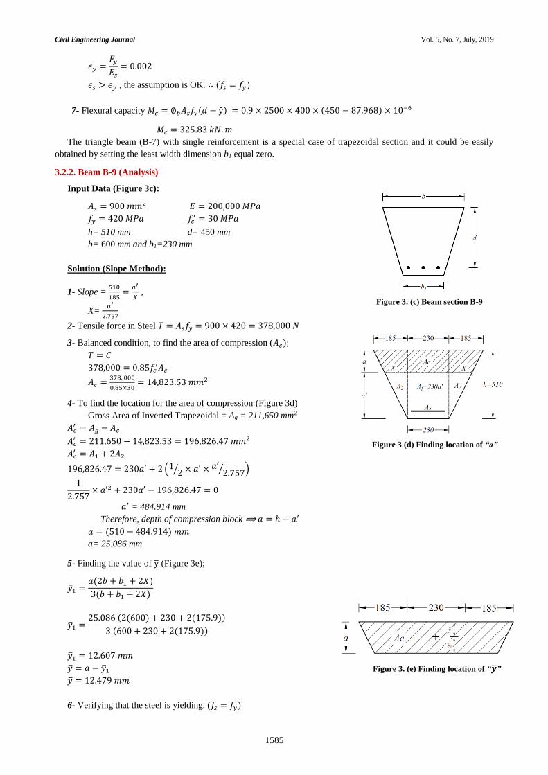
3.2.2. Beam B-9 (Analysis)
Input Data (Figure 3c):
𝐴𝑠 = 900 𝑚𝑚2 𝐸 = 200,000 𝑀𝑃𝑎
𝑓𝑦 = 420 𝑀𝑃𝑎 𝑓𝑐′ = 30 𝑀𝑃𝑎
h= 510 mm d= 450 mm
b= 600 mm and b1=230 mm
Solution (Slope Method):
1- Slope = 510
185=
𝑎′
𝑋 ,
X= 𝑎′
2.757
2- Tensile force in Steel 𝑇 = 𝐴𝑠𝑓𝑦 = 900 × 420 = 378,000 𝑁
3- Balanced condition, to find the area of compression (𝐴𝑐);
𝑇 = 𝐶
378,000 = 0.85𝑓𝑐′𝐴𝑐
𝐴𝑐 =378,,000
0.85×30= 14,823.53 𝑚𝑚2
4- To find the location for the area of compression (Figure 3d)
Gross Area of Inverted Trapezoidal = Ag = 211,650 mm2
𝐴𝑐′ = 𝐴𝑔 − 𝐴𝑐
𝐴𝑐′ = 211,650 − 14,823.53 = 196,826.47 𝑚𝑚2
𝐴𝑐′ = 𝐴1 + 2𝐴2
196,826.47 = 230𝑎′ + 2 (12⁄ × 𝑎′ × 𝑎′
2.757⁄ )
1
2.757× 𝑎′2 + 230𝑎′ − 196,826.47 = 0
𝑎′ = 484.914 mm
Therefore, depth of compression block ⟹ 𝑎 = ℎ − 𝑎′
𝑎 = (510 − 484.914) 𝑚𝑚
a= 25.086 mm
5- Finding the value of y̅ (Figure 3e);
�̅�1 =𝑎(2𝑏 + 𝑏1 + 2𝑋)
3(𝑏 + 𝑏1 + 2𝑋)
�̅�1 =25.086 (2(600) + 230 + 2(175.9))
3 (600 + 230 + 2(175.9))
�̅�1 = 12.607 𝑚𝑚
�̅� = 𝑎 − �̅�1
�̅� = 12.479 𝑚𝑚
6- Verifying that the steel is yielding. (𝑓𝑠 = 𝑓𝑦)
Figure 3. (c) Beam section B-9
Figure 3 (d) Finding location of “a”
Figure 3. (e) Finding location of “�̅�”

Civil Engineering Journal Vol. 5, No. 7, July, 2019
1586
𝑎 = 25.086 𝑚𝑚
𝑐 =𝑎
𝛽= (
25.086
0.85) = 29.52 𝑚𝑚
𝜖𝑠 = (𝑑−𝑐
𝑐) 0.003 = 0.043
𝜖𝑦 =𝐹𝑦
𝐸𝑠
= 0.002
𝜖𝑠 > 𝜖𝑦 , the assumption is OK. ∴ (𝑓𝑠 = 𝑓𝑦)
7- Flexural capacity 𝑀𝑐 = ∅𝑏𝐴𝑠𝑓𝑦(𝑑 − ȳ) = 0.9 × 900 × 420 × (450 − 12.479) × 10−6
𝑀𝑐 = 148.845 𝑘𝑁. 𝑚
The Inverted triangle beam (B-10) with single reinforcement is a special case of Inverted trapezoidal section and it
could be easily obtained by setting the least width dimension b1 equal zero.
3.2.3. Beam B-11 (Hexagonal Beam Analysis)
Input Data (Figure 3f):
𝐴𝑠𝑇 = 6 ∅20 = 1884.954 𝑚𝑚2
𝑓𝑦 = 400 𝑀𝑃𝑎
𝑓𝑐′ = 30 𝑀𝑃𝑎
𝐸 = 200,000 𝑀𝑃𝑎
h= 380 mm
Solution:
To solve the Hexagonal shaped beam, it should be converted to equivalent square shape to find the required
moment capacity (Figure 3g).
1- The height for the equivalent square shape can be found as; 𝐻𝑠𝑞𝑢𝑎𝑟𝑒 = ℎ × 0.93
𝐻𝑠𝑞𝑢𝑎𝑟𝑒 = 380 × 0.93 = 353 𝑚𝑚
𝑑′ = 70 𝑚𝑚
𝐴𝑠 =𝐴𝑠𝑇
2= 3 ∅20 = 942.48 𝑚𝑚2
2- Find the depth of the compression area (a);
𝑎 =𝐴𝑠𝐹𝑦
0.85 𝑓𝑐′ 𝑏
=942.48 × 400
0.85 × 30 × 353= 41.88 𝑚𝑚
3- Verifying that the steel is yielding. (𝑓𝑠 = 𝑓𝑦)
𝑎 = 41.88 𝑚𝑚
𝑐 =𝑎
𝛽= (
41.88
0.85) = 49.27 𝑚𝑚
𝜖𝑠 = (𝑑 − 𝑐
𝑐) 0.003 = 0.014
𝜖𝑦 =𝐹𝑦
𝐸𝑠= 0.002
𝜖𝑠 > 𝜖𝑦 , the assumption is OK. ∴ (𝑓𝑠 = 𝑓𝑦)
4- Flexural capacity 𝑀𝑐 = ∅𝑏𝐴𝑠𝑓𝑦(𝑑 − 𝑎2⁄ ) = 0.9 × 942.48 × 400 × (283 − 20.94) × 10−6
𝑀𝑐 = 88.9 𝑘𝑁. 𝑚
4. Circular Beams (Group-3)
This group contains the study of circular beams. Circular beams are used but quite often in the construction Industry.
Equivalent square method is used in this study to find the design moment capacity for the circular beams. In this study,
the circular section (B-12) having different diameters are selected. The analytical results of these circular beams using
the equivalent square method are also compared with the finite element software (SAP) and the results obtained are
displayed in Table 4. Moreover, the numerical solution for finding the design capacity results for one of the circular
section (diameter D=450 mm) is also shown in this study.
Figure 3. (f) Beam section B-11
Figure 3. (g) Equivalent Square Section

Civil Engineering Journal Vol. 5, No. 7, July, 2019
1587
Table 4. Design Strength of Circular Beam
Beam
ID Circular Beams
Design Parameters Mc (kN-m)
D
(mm)
𝒇𝒚
(MPa)
𝒇𝒄′
(MPa)
𝒅′
(mm)
As
(mm2)
Flexural
Equations
Finite Element
Software
B-12
400
450
500
300
300
400
400
415
20
30
30
30
85
60
110
50
8 Φ20
6 Φ25
8 Φ25
6 Φ20
81.4
140.6
212
66.3
88.3
146.2
232
70
4.1. Beam B-12 (Circular Beam)
Input Data (Figure 4a):
𝐴𝑠𝑇 = 8 ∅20 = 2513.28 𝑚𝑚2
𝑓𝑦 = 400 𝑀𝑃𝑎
𝑓𝑐′ = 30 𝑀𝑃𝑎
𝐸 = 200,000 𝑀𝑃𝑎
D= 450 mm
Solution:
To solve the Circular shaped beam, it should be first converted to equivalent square shape to find the required moment
capacity (Figure 4b).
1- The height for the equivalent square shape can be found as; 𝐻𝑠𝑞𝑢𝑎𝑟𝑒 = 𝐷 × 0.89
𝐻𝑠𝑞𝑢𝑎𝑟𝑒 = 450 × 0.89 = 400 𝑚𝑚
𝑐𝑐 = 60 𝑚𝑚
𝐴𝑠 =𝐴𝑠𝑇
2= 4 ∅20 = 1256.64 𝑚𝑚2
2- Find the depth of the compression area (a);
𝑎 =𝐴𝑠𝐹𝑦
0.85 𝑓𝑐′ 𝑏
=1256.64 × 400
0.85 × 30 × 400= 49.3 𝑚𝑚
3- Verifying that the steel is yielding. (𝑓𝑠 = 𝑓𝑦)
𝑎 = 49.3 𝑚𝑚
𝑐 =𝑎
𝛽= (
49.3
0.85) = 58 𝑚𝑚
𝜖𝑠 = (𝑑−𝑐
𝑐) 0.003 = 0.0146
𝜖𝑦 =𝐹𝑦
𝐸𝑠
= 0.002
𝜖𝑠 > 𝜖𝑦 , the assumption is OK. ∴ (𝑓𝑠 = 𝑓𝑦)
4- Flexural capacity 𝑀𝑐 = ∅𝑏𝐴𝑠𝑓𝑦(𝑑 − 𝑎2⁄ ) = 0.9 × 1256.64 × 400 × (340 − 29) × 10−6
𝑀𝑐 = 140.6 𝑘𝑁. 𝑚
5. Results and Discussion
The results obtained using simplified method for all of the three groups are compared with the computer software.
The percentage difference for all of these sections are depicted in the bar charts (Figures 5 to 7). For the group-1 beam
sections, the percentage difference of simplified method for beams B-1, B-2 and B-6 with the finite element software
ranges below 5% while the remaining beam sections B-3, B-4 and B-5 lies within 5% to 10 % respectively.
Each beam section of Group-2 beams (B-7 to B-11) are analysed with different leg dimensions and each beam
section showed promising results as the percentage difference ranges within 1% to 8%. Circular beam sections (Group-
3) are analysed using the equivalent square section method. Four different circular beam sections with different
diameters (B-12a – B-12d) are analysed in this group using simplified method and their results varies within a percentage
difference of 5% to 10% with the finite element software.
Figure 4. (a) Beam section B-11
Figure 4. (b) Equivalent Square Section

Civil Engineering Journal Vol. 5, No. 7, July, 2019
1588
Figure 5. Percentage difference for straight edged beams (Group-1)
Figure 6. Percentage difference for sloped edged beams (Group -2)
Figure 7. Percentage difference for circular beams (Group -3)
6. Conclusion
This paper presents simple method to estimate the flexural capacity of different irregular shaped beam section Mc.
Three different types of the irregular beams groups (beams with straight edges, beams with sloped edges, and circular
beams) are studied using the simplified method. This study helps in analysing the flexural capacity of all irregular shaped
0
2.5
5
7.5
10
12.5
15
B - 1 B - 2 B - 3 B - 4 B - 5 B - 6
% a
ge
Dif
fere
nce
0
2.5
5
7.5
10
12.5
15
B - 7 B - 8 B - 9 B - 1 0 B - 1 1
% a
ge
Dif
fere
nce
0
2.5
5
7.5
10
12.5
15
B - 1 2 ( a ) B - 1 2 ( b ) B - 1 2 ( c ) B - 1 2 ( d )
% a
ge
Dif
fere
nce

Civil Engineering Journal Vol. 5, No. 7, July, 2019
1589
beams presented in this paper. The moment capacities obtained from the simplified method of these irregular shaped
beams showed promising results when compared with the finite element software (SAP) with a percentage difference
of 1% to 10 % respectively.
The moment capacity for the first two groups (beams with straight edges and beams with sloped edges) can be found
by using the similar flexural equation used in case of rectangular beam with single reinforcement. For the third group
(circular beams) and for the hexagonal shaped beam sections, equivalent square method is used to find the flexural
capacities as this approach is quite simple to use and results obtained are quite close to the finite element software results.
7. Conflicts of Interest
The authors declare no conflict of interest.
8. References
[1] ACI Committee 318. "Building Code Requirements for Structural Concrete (ACI 318-14): An ACI Standard: Commentary on
Building Code Requirements for Structural Concrete (ACI 318R-14): ACI Report." American Concrete Institute, 2014.
[2] Lu, Renjian, Yuanhui Luo, and Joel P. Conte. “Reliability Evaluation of Reinforced Concrete Beams.” Structural Safety 14, no.
4 (July 1994): 277–298. doi:10.1016/0167-4730(94)90016-7.
[3] Baji, H., and H. R. Ronagh. “Investigating the Reliability of RC Beams of Tall Buildings Designed Based on the New ACI 318-
05/ASCE 7-05.” The Structural Design of Tall and Special Buildings 21, no. 8 (November 12, 2010): 592–604.
doi:10.1002/tal.638.
[4] Hassoun, M. Nadim, and Akthem Al-Manaseer. Structural concrete: theory and design. John wiley & sons, 2012.
[5] Siddiqi, Zahid Ahmad. Concrete Structures: Part-I. Zahid Ahmad Siddiqi, 2013.
[6] McCormac, Jack C., and Russell H. Brown. Design of reinforced concrete. John Wiley & Sons, 2015.
[7] Mahzuz, H.M.A. “Performance Evaluation of Triangular Singly Reinforced Concrete Beam.” International Journal of Structural
Engineering 2, no. 4 (2011): 303. doi:10.1504/ijstructe.2011.042896.
[8] Mansur, M. A., and Kiang-Hwee Tan. Concrete beams with openings: Analysis and design. Vol. 20. CRC Press, 1999.
[9] Al-Ansari, Mohammed S. “Reliability and Flexural Behavior of Triangular and T-Reinforced Concrete Beams.” International
Journal of Advanced Structural Engineering 7, no. 4 (November 13, 2015): 377–386. doi:10.1007/s40091-015-0106-5.
[10] Orumu, Solomon Teminusi. "Universal Design Model for Reinforced Concrete Sections in Flexure." (2013).
[11] Cosenza, Edoardo, Carmine Galasso, and Giuseppe Maddaloni. "Simplified assessment of bending moment capacity for RC
members with circular cross-section." In third international fib Congress and Exhibition & PCI Annual Convention and Bridge
Conference”. 2010.
[12] Al-Ansari, Mohammed S., and Ahmed B. Senouci. "MATHCAD: Teaching and Learning Tool for Reinforced Concrete Design."
International Journal of Engineering Education 15, no. 1 (1999): 64-71.