simplified theory for flow pattern prediction in perforated tubes
TRANSCRIPT
S
RR
a
ARRA
1
pjssrpgotsttlfhtlaoiHKe
0d
Nuclear Engineering and Design 239 (2009) 1725–1732
Contents lists available at ScienceDirect
Nuclear Engineering and Design
journa l homepage: www.e lsev ier .com/ locate /nucengdes
implified theory for flow pattern prediction in perforated tubes
aj Kumar Singh, A. Rama Rao ∗
eactor Engineering Division, Bhabha Atomic Research Centre, Hall-7, RED, BARC, Mumbai 400085, India
r t i c l e i n f o
rticle history:eceived 10 September 2008eceived in revised form 6 April 2009ccepted 26 May 2009
a b s t r a c t
Perforated tubes are widely used in nuclear industries for many critical process and regulatory purpose. Inpressurized heavy water reactors (PHWRs), perforated tubes are used in moderator system, in shutdownsystem for poison injection and in reactivity mechanism for housing the safety bank inside the core. Inthe moderator system and in poison injection loop the flow of fluid through perforated tubes match the
requirement of the system. One is a steady state flow and the other is transient flow. The design of perfo-rated tube involves arriving at the size of the holes, its spacing along the length and in the circumference.For PHWRs, the design is validated by rigorous experimentation. The paper offers a simplified analyticalmethod along with detail theoretical steps required in arriving at the design of perforated tubes that canmeet the end objective. For existing tubes, the given formulations can be used for estimating the flowprofile. The paper presents case study of predicted flow through perforated tube and its validation by experimental results.. Introduction
In nuclear industry, perforated tubes are used in the core toerform many important functions of fluid injection, circulation
ets and also in the form of guide tubes inside the core. In pres-urized heavy water reactors (PHWRs), perforated guide tubesubmerged in flowing heavy water houses the shut-off rods of theeactivity mechanism. Perforated tubes are also used for injectingoison in the reactor under transient condition in case of emer-ency shutdown (Bhardwaj and Dixit, 2005). The type and patternf perforation on the tubes depend on the particular function of theube in a particular system of the plant. For example, the horizontalparger tubes of moderator system in Madras Atomic Power Sta-ion in India are having varying size and pitch of the holes alonghe length of the tube to achieve a desired flow profile. The size andocation of holes were arrived based on series of mockup trial in aull-scale test facility aimed to carry out study of flow pattern andydraulic resistances to optimize the flow pattern from the spargerube (Pilkhwal et al., 1989, 1987). Perforated structures also playead role in the analysis of flow field in lower plenum of PWR (Jeongnd Han, 2008; Rohde et al., 2007) and in reactor pressure vesself VVER-1000 reactor (Böttcher, 2008). The emergency core cool-
ng injection in the new generation reactor under design (Advancedeavy Water Reactor AHWR) is through perforated tubes (Sinha andakodkar, 2006; AHWR/PREL/DR/37100/02/Rev. 0 2005; Srivastavat al., 2008).∗ Corresponding author. Tel.: +91 2225595145; fax: +91 2225505151.E-mail address: [email protected] (A. Rama Rao).
029-5493/$ – see front matter © 2009 Elsevier B.V. All rights reserved.oi:10.1016/j.nucengdes.2009.05.028
© 2009 Elsevier B.V. All rights reserved.
In view of large-scale use of perforated tube as in-core compo-nents in the reactors, it becomes important to study outflow patternthrough perforated tubes. Through computational methods by solv-ing 3-D Navier Stokes equations, outflow pattern can be predictedfor given perforated tube. But, if some flow pattern is needed andperforated tube is to be designed to meet the requirement, CFDmethod cannot be directly used. CFD methods can predict flowwhen geometry is known, but cannot easily configurate the geom-etry for a given flow. So it becomes important to develop simplifiedtheories to study outflow pattern and predict perforations (holesize and pitch variations with length) needed for the desired flowpattern.
The paper is about the mathematical approach to predict theflow pattern and validate the results with experimental data. Thestudy is divided into two parts. In first part steady state flow profileis considered in which inlet flow velocity into the perforated tube isnot varying with time. A simplified model is made and solved ana-lytically. Then results are compared with experiments. Perforatedtube design for some desired flow pattern is also derived. In thesecond part transient case is studied wherein flow velocity varieswith time.
2. Steady state flow profile
For the steady state flow in a pipe, the following are assumed for
arriving at the formulation:1. Input velocity in the tube is constant with time.2. The flow is taken as incompressible for mass balance equation.
1 ineerin
3
t
2
v
v
wPv
2
b
d
w
ah
l
T
726 R.K. Singh, A. Rama Rao / Nuclear Eng
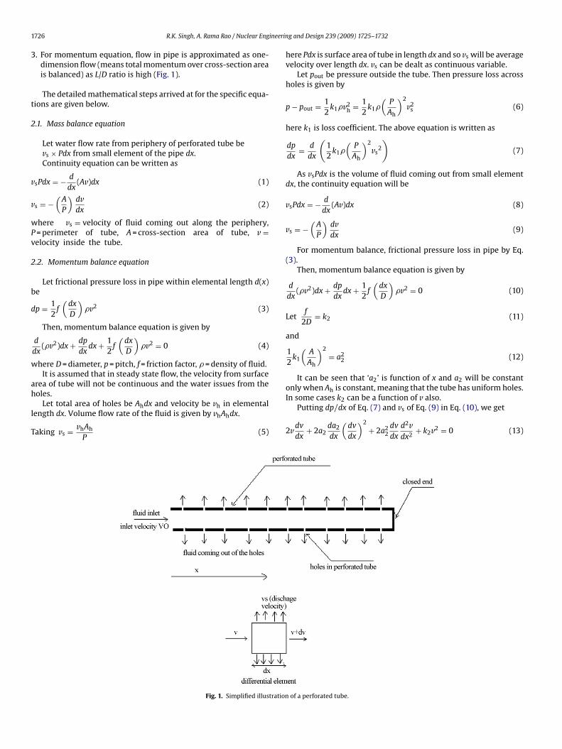
. For momentum equation, flow in pipe is approximated as one-dimension flow (means total momentum over cross-section areais balanced) as L/D ratio is high (Fig. 1).
The detailed mathematical steps arrived at for the specific equa-ions are given below.
.1. Mass balance equation
Let water flow rate from periphery of perforated tube bevs × Pdx from small element of the pipe dx.Continuity equation can be written as
sPdx = − d
dx(Av)dx (1)
s = −(
A
P
)dvdx
(2)
here vs = velocity of fluid coming out along the periphery,= perimeter of tube, A = cross-section area of tube, v =elocity inside the tube.
.2. Momentum balance equation
Let frictional pressure loss in pipe within elemental length d(x)e
p = 12
f(
dx
D
)�v2 (3)
Then, momentum balance equation is given by
d
dx(�v2)dx + dp
dxdx + 1
2f(
dx
D
)�v2 = 0 (4)
here D = diameter, p = pitch, f = friction factor, � = density of fluid.It is assumed that in steady state flow, the velocity from surface
rea of tube will not be continuous and the water issues from the
oles.Let total area of holes be Ahdx and velocity be vh in elementalength dx. Volume flow rate of the fluid is given by vhAhdx.
aking vs = vhAh
P(5)
Fig. 1. Simplified illustration
g and Design 239 (2009) 1725–1732
here Pdx is surface area of tube in length dx and so vs will be averagevelocity over length dx. vs can be dealt as continuous variable.
Let pout be pressure outside the tube. Then pressure loss acrossholes is given by
p − pout = 12
k1�v2h = 1
2k1�
(P
Ah
)2v2
s (6)
here k1 is loss coefficient. The above equation is written as
dp
dx= d
dx
(12
k1�(
P
Ah
)2vs
2
)(7)
As vsPdx is the volume of fluid coming out from small elementdx, the continuity equation will be
vsPdx = − d
dx(Av)dx (8)
vs = −(
A
P
)dvdx
(9)
For momentum balance, frictional pressure loss in pipe by Eq.(3).
Then, momentum balance equation is given by
d
dx(�v2)dx + dp
dxdx + 1
2f(
dx
D
)�v2 = 0 (10)
Letf
2D= k2 (11)
and
12
k1
(A
Ah
)2
= a22 (12)
It can be seen that ‘a2’ is function of x and a2 will be constantonly when Ah is constant, meaning that the tube has uniform holes.
In some cases k2 can be a function of v also.Putting dp/dx of Eq. (7) and vs of Eq. (9) in Eq. (10), we get
2vdv
dx+ 2a2
da2
dx
(dv
dx
)2
+ 2a22
dv
dx
d2vdx2
+ k2v2 = 0 (13)
of a perforated tube.

ineering and Design 239 (2009) 1725–1732 1727
v
2
k
a
o
p‘ihd
3p
i
2
s
A
A
s
e
v
x
c
v
t
heta
dkdvt
Fig. 2. (a) Velocity inside pipe v versus x. (b) Discharge profile vs versus x.
R.K. Singh, A. Rama Rao / Nuclear Eng
By non-dimensionalising ‘x’ with total length L and v with initialelocity v0 Eq. (13) becomes
vdv
dx+ 2a
da2
dx
(dv
dx
)2
+ 2a2 dv
dx
d2vdx2
+ kv2 = 0 (14)
= k2L (15)
= a2
L(16)
Using this equation, the pitch and size of hole along the lengthf tube for the desired fluid discharge profile can be calculated.
Firstly, the velocity profile for equal diameter holes and uniformitch is found and then the effect of variable parameters like ‘a’ and
k’ on velocity profile is estimated. The result of above estimations compared with experimental result and the required number ofoles, hole diameter and pitch is found out for the desired fluidischarge profile.
. Velocity profile in tubes with uniform hole with equalitch
In Eq. (13), parameter a2 is taken constant as pitch and hole sizes uniform.
So Eq. (13) can be written as
vdvdx
+ 2a22
dvdx
d2vdx2
+ k2v2 = 0 (17)
This is non-linear differential equation, which is required to beolved.
Let inlet velocity be v0 and length of perforated tube be L.The boundary conditions are
t x = 0; v = v0 (18)
t x = L; v = 0 (19)
Let L = 0.225 m, v0 = 1 m/s, a = 0.1516 and k = 4.5 typically forhort length perforated tube.
Substituting dv/dx = p and v/p = � for solving the differentialquation. Solution becomes
= 0.913(�2)0.52
(� + 0.487)−0.075
× (�2 − 0.042� + 0.02)−0.486
e−0.114 tan−1 (�−0.021)0.14 (20)
= 0.2 + 0.018 ln(� + 0.487)2
�2 − 0.042� + 0.02+ 0.133 tan−1 (� − 0.021)
0.14(21)
This gives parametric relation between v and x and vs can bealculated by
s = −(
A
P
)dv/d�
dx/d�(22)
The plots of v and vs versus x is as shown in Fig. 2a and b, respec-ively.
It can be seen from Fig. 2a that more water flows out from theoles at the closed end and little water flows out from holes at thentry of the tube. How ever, this is not general profile. The change inhe profile can be assessed from the dimensionless Eq. (14). Therere two parameters a and k which influence the discharge profile.
It is important to see that when length of pipe increases, a
ecreases and k increases and when diameter of tube increases,does not change while a increases. Fig. 3 shows variation of non-imensionalised discharge velocity when k is held constant and a isaried in Eq. (14). It can be seen that when a increases discharge athe end of the tube decreases. In the above figure, k = 0.787 and a isFig. 3. Discharge velocity versus x.
varied from 0.6 (series 6) to 1.6 (series 24). In between, a increasesuniformly. At series j, value of a is 0.6 + 0.055(j − 6).
Fig. 4 shows the trends of discharge profile when a is held con-stant and k is varied. It can be seen that as k increases, dischargedecreases towards the end and increases at the beginning. In shortpipes, discharge is more at ends while in very long pipes dischargeis more at beginning and less towards the ends.
In Fig. 4, a is constant at 0.6 and k varied from 1.28 (series 6) to5.78 (series 24) and in between k increases uniformly. At series j,value of k is 1.28 + 0.25(j − 6).
4. Discharge profile by experiments
A few sets of experiments were carried out to verify the dis-
charge profile. The schematic of the setup is shown in Fig. 5. Thealuminum tube of 10 mm in diameter and 0.225 m long was usedin the experiment. The holes in the tube were 3.0 mm in diame-ter. Value of parameter a and k was 0.48 and 0.525, respectively.
1728 R.K. Singh, A. Rama Rao / Nuclear Engineerin
TTastIa
vcsT
5d
v
Right hand side of Eq. (29) is completely known. As a(x) is a
Fig. 4. Discharge velocity versus x.
ube was placed inside the tank, which has three compartments.he tube was connected to the tap water by a flexible hose. Themount of fluid in various compartments was measured with mea-uring flask and pipette. With the measure of time taken for fillinghe total volume of water, the inlet flow velocity was also measured.t is easy to see that filling rate of some compartment can be givens = (vat beginning of compartment − vat end of compartment) × A.
From inlet velocity and volume of fluid in each compartmentelocity in side the pipe at beginning of each compartment was cal-ulated. The results were then compared with analytical solution ashown. Fig. 6 shows the experimental and analytical velocity plots.he analytical solution matches very well with the experiment.
. Determining hole diameter or pitch for a desiredischarge profile
Let discharge profile be a function of x as shown below.
s = f (x) (23)
Fig. 5. Experime
g and Design 239 (2009) 1725–1732
Then from Eq. (2)
v = −∫ (
P
A
)f (x)dx (24)
In Eq. (14) “k” may be function of “v” and “x” and shown as k(v, x).In Eq. (14) putting v from Eq. (24) we get
2ada
dxf (x)2+2f (x)
∫f (x)dx + 2a2f (x)f ′(x)+k(v, x)
(∫f (x)dx
)2
= 0
(25)
da2
dx+ 2
1f (x)
∫f (x)dx + 2a2 f ′(x)
f (x)+ k(v, x)
(∫f (x)dx
)2
f (x)2= 0 (26)
Now e
∫2(f ′(x)/f (x))dx
will be the integrating factor.
d
dx(e
∫2(f ′(x)/f (x))dx
a2) + 2e
∫2(f ′(x)/f (x))dx 1
f (x)
∫f (x)dx
+e
∫2(f ′(x)/f (x))dx
k
(−
∫ (P
A
)f (x)dx, x
) (∫f (x)dx
)2
f (x)2= 0 (27)
a2 = ce−∫
2(f ′(x)/f (x))dx − e−∫
2(f ′(x)/f (x))dx
∫ (2e
∫2(f ′(x)/f (x))dx 1
f (x)
∫f (x)dx
+e
∫2(f ′(x)/f (x))dx
k
(−∫ (
P
A
)f (x)dx, x
) (∫f (x)dx
)2
f (x)2
)dx (28)
where “c” is constant. Simplifying the equation
a2 = c
f 2(x)− 1
f 2(x)
∫(2f (x)
∫f (x)dx + k
(−
∫ (P
A
)f (x)dx, x
)
×(∫
f (x)dx)2
)dx (29)
since e
∫2(f ′(x)/f (x))dx = e2 ln(f (x)) = f 2(x) (30)
function of x, it can be found as
a = A(k1/2)0.5
AhL(31)
ntal setup.

R.K. Singh, A. Rama Rao / Nuclear Engineerin
Fig. 6. Velocity plot in the tube. Blue line is theoretical and pink points are experi-ments. (For interpretation of the references to color in this figure legend, the readeris referred to the web version of the article.)
d
s
A
h
diptfu
6
tsar
csa
Fig. 7. Variation of parameter ‘a’ to get uniform flow profile.
So Ah(x, dh) can be calculated. k1 should be function of dh (holeiameter) as well.
If pitch of hole is p1 and number of holes on periphery is n andince Ah is area of holes per unit length Ah is given by
h = �nd2h
4p1(32)
ere dh is hole diameter.The diameter of the hole or pitch variation for each x for desired
ischarge profile could be calculated. As an example, if same flows desired from all the holes, putting f(x) = c in Eq. (29), variation ofarameter a along the length is obtained. Fig. 7 shows the varia-ion parameter a along the length of the tube for various k. k variesrom 1.1 to 3.1 from series 1 to series 9, and in between k increasesniformly. At series j, value of k is 1.1 + 0.25(j − 1).
. Transient flow profile
Unlike in steady state flow condition, flow velocity underransient condition will be a function of time. In the secondaryhutdown system of pressurized heavy water reactor design suchcondition exists. Poison is injected into calandria through perfo-
ated tubes with high velocity in a short time.In this section we will deal with general case when velocity can
hange with time. Continuity equation is same as in the case ofteady state, however in momentum equation, one inertia term gets
dded as shown below,∂(�v)∂t
+ ∂
∂x(�v2) + ∂p
∂x+ 1
2f(
1D
)�v2 = 0 (33)
g and Design 239 (2009) 1725–1732 1729
Substituting value of p as in steady state case we get,
∂v∂t
+ 2v∂v∂x
+ 2a2∂a2
∂x
(∂v∂x
)2
+ 2a22 ∂v
∂x
∂2v∂x2
+ k2v2 = 0 (34)
In this equation a2 and k2 have same meaning.In steady state case, we were able to find size of hole and their
pitch variation along length for every desired profile. For everygiven discharge profile f(x), hole diameter is given by Eq. (29). Inthe case of transient flow, inlet velocity is the function of time v0(t).But in transient case, for every given discharge profile f(x, t), onecannot make perforated tubes but hole diameter, pitch and v0(t)can be varied. So, many f(x, t) are not possible by perforated tubes.So it becomes important to find which of the discharge profiles arepossible.
To find possibility of some discharge profile through the perfo-rated tubes,
If discharge profile is f(x, t) then from continuity Eq. (2) similarto Eq. (24)
v = −∫ (
P
A
)f (x, t)dx (35)
Putting v into Eq. (34)
−(
A
P
)∫∂f (x, t)
∂tdx + 2a2
da2
dxf (x, t)2 + 2f (x, t)
∫f (x, t)dx
+ 2a22f (x, t)
∂f (x, t)∂x
+ k2(v, x)
(∫f (x, t)dx
)2
= 0 (36)
In the above equation f is function of x and t and a2 is function ofx only. Eq. (34) is non-linear differential equation in a2. It is requiredto find the condition for which the desired f(x, t) is possible or not.
Dividing Eq. (34) by f(x, t)2
−(
A
Pf 2(x, t)
)∫∂f (x, t)
∂tdx + 2a2
da2
dx+ 2
f (x, t)
∫f (x, t)dx
+ 2a22
f (x, t)∂f (x, t)
∂x+ k2(v, x)
f (x, t)2
(∫f (x, t)dx
)2
= 0 (37)
and partially differentiating w.r.t. time
∂
∂t
(−
(A
Pf 2(x, t)
)∫∂f (x, t)
∂tdx+ 2
f (x, t)
∫f (x, t)dx+ 2a2
2f (x, t)
∂f (x, t)∂x
+k2(v, x)
f (x, t)2
(∫f (x, t)dx
)2)
+ ∂
∂t
(2a2
da2
dx
)= 0 (38)
In the above equation
∂
∂t
(2a2
da2
dx
)= 0 (39)
Since a2 is function of x only. Hence equation becomes
∂
∂t
(−
(A
Pf 2(x, t)
)∫∂f (x, t)
∂tdx + 2
f (x, t)
∫f (x, t)dx
+ k2(v, x)
f (x, t)2
(∫f (x, t)dx
)2)
+2a22
∂
∂t
(1
f (x, t)∂f (x, t)
∂x
)= 0 (40)
if∂
∂t
(1
f (x, t)∂f (x, t)
∂x
)/= 0 (41)

1 ineerin
a
A
[
p
f
a
730 R.K. Singh, A. Rama Rao / Nuclear Eng
Dividing the above equation by (∂/∂t)((1/f (x, t))(∂f (x, t)/∂x))nd partially differentiating w.r.t. time.
∂
∂t
(1
(∂/∂t)((1/f (x, t))(∂f (x, t)/∂x))∂
∂t
(−
(A
Pf 2(x, t)
)∫∂f (x, t)
∂tdx
+ 2f (x, t)
∫f (x, t)dx + k2(v, x)
f (x, t)2
(∫f (x, t)dx
)2))
+ ∂(2a22)
∂t= 0
(42)
s∂(2a2
2)∂t
= 0 (43)
The above equation simplifies to
∂
∂t
(1
(∂/∂t)((1/f (x, t))(∂f (x, t)/∂x))∂
∂t
(−
(A
Pf 2(x, t)
)∫∂f (x, t)
∂tdx
+ 2f (x, t)
∫f (x, t)dx + k2(v, x)
f (x, t)2
(∫f (x, t)dx
)2))
= 0 (44)
Earlier it was assumed that
∂
∂t
(1
f (x, t)∂f (x, t)
∂x
)/= 0
But if
∂
∂t
(1
f (x, t)∂f (x, t)
∂x
)= 0 (45)
Then Eq. (40) becomes
∂
∂t
(−
(A
Pf 2(x, t)
)∫∂f (x, t)
∂tdx + 2
f (x, t)
∫f (x, t)dx
+k2(v, x)
f (x, t)2
(∫f (x, t)dx
)2)
= 0 (46)
Since Eqs. (45) and (46) are equal to zero they can be written as
∂
∂t
(−
(A
Pf 2(x, t)
)∫∂f (x, t)
∂tdx + 2
f (x, t)
∫f (x, t)dx
+ k2(v, x)
f (x, t)2
(∫f (x, t)dx
)2)]2
+[
∂
∂t
(1
f (x, t)∂f (x, t)
∂x
)]2
= 0
(47)
From the above analysis it is implied that some profile f(x, t) isossible only when either Eq. (44) or (47) is satisfied.
The size of the hole and pitch variation along length of the tubeor some velocity profile is given by Eq. (48) below.
Solving Eq. (34) for a2
22 = g(t)
f 2(x, t)− 1
f 2(x, t)
∫ (2f (x, t)
∫f (x, t)dx
( ∫ (P) )(∫ )2
+k −A
f (x, t)dx, x f (x, t)dx
−A
P
∫∂f (x, t)
∂tdx
)dx (48)
g and Design 239 (2009) 1725–1732
In the above g(t) is arbitrary function of time. The desired inletvelocity function for some discharge velocity profile can be givenas
v0(t) =(
−∫ (
P
A
)f (x, t)dx
)at x=0
(49)
It is now required to find some solutions.Analyzing Eq. (47), it implies that both Eqs. (45) and (46) are
satisfied.
∂
∂t
(1
f (x, t)∂f (x, t)
∂x
)= 0
and
∂
∂t
(−
(A
Pf 2(x, t)
)∫∂f (x, t)
∂tdx + 2
f (x, t)
∫f (x, t)dx
+k2(v, x)
f (x, t)2
(∫f (x, t)dx
)2)
= 0
Since Eq. (47) is sum of squares, both should individually equalto zero.
Eq. (45) ((∂/∂t)((1/f (x, t))(∂f (x, t)/∂x)) = 0) implies
1f (x, t)
∂f (x, t)∂x
= f1(x) (50)
where f1(x) is arbitrary function of x. It can also be written as
∂(ln f (x, t))∂x
= f1(x) (51)
On integrating
ln(f (x, t)) =∫
f1(x)dx + g1(t) (52)
where g1(t) is arbitrary function of t.
f (x, t) = g1(t)e∫
f1(x)dx (53)
Since f1(x) is arbitrary function of x, so e∫
f1(x)dx is also arbitrary.
Let us denote f2(x) = e∫
f1(x)dx (54)
f (x, t) = g1(t)f2(x) (55)
It gives an important inference that (∂/∂t)((1/f (x, t))(∂f (x, t)/∂x)) = 0 if and only if f(x, t) is separable.g1(t) will act as magnifying factor shape of f(x, t) will be preserved.It will lead to practically important solutions.
Putting f (x, t) = g1(t)f2(x) in Eq. (46) and taking k2 as constantfor simplicity.
∂
∂t
(−
(A
Pf22(x)g1
2(t)
)g′
1(t)
∫f2(x)dx+ 2
g1(t)f2(x)
∫g1(t)f2(x)dx
+ k2
g1(t)2f2(x)2
(∫g1(t)f2(x)dx
)2)
= 0 (56)
so
−(
A
Pf22(x)g1
2(t)
)g′
1(t)
∫f2(x)dx + 2
g1(t)f2(x)
∫g1(t)f2(x)dx
+ k2
g1(t)2f2(x)2
(∫g1(t)f2(x)dx
)2
= d1(x) (57)
here d1(x) is arbitrary function.

ineering and Design 239 (2009) 1725–1732 1731
(
h
P
s
f(h
d(((
c
g
a
2
f
O
e
f
f
d
f
R.K. Singh, A. Rama Rao / Nuclear Eng
On further simplification,∫f2(x)dx
f22(x)
(− Ag′
1(t)
Pg12(t)
)+ 2
∫f2(x)dx
f2(x)+ k2
f2(x)2
(∫f2(x)dx
)2
= d1(x) (58)
Now dividing the above equation by(∫
f2(x)dx)
/f22(x)
− Ag′1(t)
Pg12(t)
)+ 2f2(x) + k2
∫f2(x)dx = d2(x)
ere d2(x) = d1(x)(f22(x)/
∫f2(x)dx) (59)
utting
∫f2(x)dx = f3(x) (60)
o
2(x) = df3(x)dx
= f ′3(x) (61)
Ag′1(t)
Pg12(t)
)= 2f ′
3(x) + k2f3(x) − d2(x) = c (62)
ere c is constant.Since Ag′
1(t)/Pg21(t) is function of t only and 2f ′
3(x) + k2f3(x) −2(x) is function of x only, they can be equal only if both are constant.
Ag′1(t)
Pg12(t)
)= c (63)
∂
∂t
(1
g1(t)
))= −Pc
A(64)
1g1(t)
)= −Pc
At + c1 (65)
1g1(t)
= −Pc
At + c1 (66)
1 is a constant.
1(t) = 1−(Pc/A)t + c1
(67)
nd
f ′3(x) + k2f3(x) = c + d2(x) (68)
′3(x) + k2
2f3(x) = c
2+ 1
2d2(x) (69)
Multiplying ek2x/2 both the sides
d
dx(ek2x/2f3(x)) = c
2ek2x/2 + ek2x/2
2d2(x) (70)
n integrating
k2x/2f3(x) = c
k2ek2x/2 +
∫ek2x/2
2d2(x)dx (71)
3(x) = c
k2+ e−k2x/2
∫ek2x/2
2d2(x)dx (72)
2(x) = f ′3(x) = d
dx
(e−k2x/2
∫ek2x/2
2d2(x)dx
)= d3(x) (73)
3(x) is arbitrary function.Hence
(x, t) = f2(x)g1(t) = d3(x)−(Pc/A)t + c1
(74)
Fig. 8. Discharge profile varying x with time.
Eq. (74) is the solution, which satisfies (47).In this solution, since f(x, t) is separable, g1(t) acts as magnifi-
cation factor that is keeping the shape same but amplifying withtime. It can seen that d3(x) is arbitrary so it can seen that d3(x) isarbitrary so it can take any shape such as cos(x), polynomial etc. inwhich the time part is fixed and only constants can change.
This enables choosing any shape of discharge profile withrespect to x.
Now calculating a2(x) for separable f(x, t) from Eq. (48) andchoosing arbitrary
g(t) = g1(t)2 (75)
We get
a2(x) = 1
d3(x)2
(1 + c
∫d3(x)dx −
∫ (2d3(x)
∫d3(x)dx
+k2
(∫d3(x)dx
)2)
dx
)(76)
By choosing d3(x) = ex in Eq. (74) and other constants suitably, toget
f (x, t) = ex
t + 1(77)
Plot of f(x, t) for various t is shown in Fig. 8.In the above figure, series 1 is at time t = 0, and series 10 is at
time t = 1 s. In between, for series J, time is t = (J × 0.1). As it canbe seen, the shape of discharge profile does not change with timebut they are only amplifying. This is true for f(x, t) satisfying Eq.(47). However there will be many other f(x, t) possible which willsatisfy Eq. (44) and those will have different properties. This typeof transient discharge profile is important in industry and real lifecases since flow variation across length can be decided based ondemand to suit the system requirement.
7. Conclusion
Perforated tubes are widely used in industries and more so innuclear industry. Various types of flow profiles are desired fromthese tubes depending upon the process and location. An attempthas been made to provide an analytical solution to model perfo-rated tubes with mass and momentum balance equation. Solutionsto the equations have been obtained indicating flow behavior inperforated tubes.
The study is divided into two parts. In the first part, steady
state flow into the tube is considered. A simplified model is madeand its step-by-step analytical solution is obtained. The results arecompared with experimental observations. For some desired flowpattern the perforated tube was designed using derived formula-tions.
1 ineerin
iposiai
AADfkLPpvv�
a
k
Sinha, R.K., Kakodkar, A., 2006. Design and development of the AHWR—the Indianthorium fueled innovative nuclear reactor. Nuclear Engineering and Design 236(April (7)), 683–700.
Srivastava, A., Lele, H.G., Ghosh, A.K., Kushwaha, H.S., 2008. Uncertainty analy-
732 R.K. Singh, A. Rama Rao / Nuclear Eng
In the second part transient case of time varying flow veloc-ty was considered. Equations for transient flow behavior in theerforated tube was evolved and analyzed. Finally conditions tobtained a particular desired flow from perforated is arrived at. It ishown that if flow behavior is obtainable, then the size of the holes,ts pitch, input velocity variation with time could be calculated tochieve desired flow behavior. Some practical cases are discussedn the paper.
cross-section area of tube (m2)h cross-section area of holes per meter of length (m)
diameter of the tube (m)friction factor
1 loss coefficient (m2)length of the tube (m)perimeter of the tube (m)pitch of the holes
s velocity of fluid coming out along the periphery (m/s)velocity inside the tube (m/s)
density of fluid (kg/m3)k0.51A
LAhfL2D
g and Design 239 (2009) 1725–1732
References
Bhardwaj, S.A., Dixit, 2005. Tarapur Atomic Power Project-3&4: design innovations.An International Journal of Nuclear Power 19 (1–4).
Jeong, J.H., Han, B.-S., 2008. Coolant flow field in a real geometry of PWR downcomerand lower plenum. Annals of Nuclear Energy 35 (April (4)), 610–619.
Böttcher, M., 2008. Detailed CFX-5 study of the coolant mixing within the reactorpressure vessel of a VVER-1000 reactor during a non-symmetrical heat-up test.Nuclear Engineering and Design 238 (March (3)), 445–452.
Pilkhwal, D.S., Vijyan, P.K., Markandeya, S.G., Saha, D., Venkatraj, V., 1989. Designanalysis for optimization of size and number of holes in the proposed spargertube for MAPS reactor from consideration of flow and velocity distribution. AnInterim Report RED/AK/32000/89.
Pilkhwal, D.S., Vijyan, P.K., Venkatraj, V., 1987. Pressure drop calculations for the fuellocator of 500 MWe PHWR. Report no. 005/Dev./05011-1.(PO).
Preliminary design report of AHWR fuel assembly. AHWR/PREL/DR/37100/02/Rev. 0dated May 2005.
Rohde, U., Höhne, T., Kliem, S., Hemström, B., Scheuerer, M., Toppila, T., Aszodi, A.,Boros, I., Farkas, I., Mühlbauer, P., Vyskocil, L., Klepac, J., Remis, J., Dury, T., 2007.Fluid mixing and flow distribution in a primary circuit of a nuclear pressurizedwater reactor—validation of CFD codes. Nuclear Engineering and Design 237(September (15–17)), 1639–1655.
sis of LBLOCA for AHWR. Annals of Nuclear Energy 35 (February (2)), 323–334.