simulating systems in ground vehicle design -...
TRANSCRIPT

Simulating Systems in Ground
Vehicle Design Frederick J. Ross
Director, Ground Transportation

Maturity of Simulation
– Growing from validation to virtual simulation
Simulating Systems
– Driving virtual prototype to look at early design behaviors
Agenda: Simulating Systems

System Simulation Maturity Model
Validate (software)
Troubleshoot
Predict
Automate
Optimize
Ultimate Goal: Find best design in shortest time
Increased
ROI
Critical inversion point
(from reactive to
proactive engineering)
As simulation matures, greater return of
investment is seen.
– Each analysis goes through phase.
– First, the process needs to be validated.
– Once validated, engineers start taking
advantage of the tool to troubleshoot
existing designs.
– Key turning point in simulation is where
the use becomes more predictive
• Replace test by virtual simulation
– Next key turning point is automation
• Automation leads directly into
optimization. To build the best design
in the shortest period.
• Ease-of-Use to run design
modifications

Powertrain Simulation Roadmap
Component Analysis • Port Flow • Coolant Flow • Intake/Exhaust Manifold flow
1 Transient Behavior • Couple Simulation to 1D Code • Look at EGR mixing • Exhaust manifold temperatures
2
System Analysis • Coolant Filling • Crank Case Ventilation • Oil Circuits • Turbo Charger • Aftertreatment
3
Environment Evaluation • Dynamometer Testing • Engine in Vehicle • Drive Cycle Simulation
4
Inc
rea
se
d R
OI
Complexity
Validate
Troubleshoot
Predict
Automate
Optimize
Component Analysis System Analysis

Automation: Intake Port Flow Analysis
Virtual Port Flow Tool
Challenge
Combustion efficiency depends a lot on the intake
air flow, tumble, and swirl to get complete, and
fast burn. CFD has proven to be a valuable tool to
optimize port flow. Engineer needs quick design
studies to evaluate flow efficiency at different
valve lifts.
Solution • Automated tool has been built and designed.
• Port Flow optimization.
• Follows work from established best practices.
• Pass data to other software/databases without
manual interactions.
Impact • Reduce errors in simulation.
• Leverage product expertise without needing
software expertise.
• Leverage the expertise of analysis to the
experts.
Return to a focus on Design as opposed to Analysis!
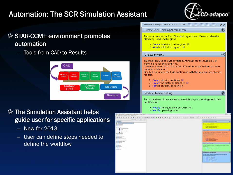
STAR-CCM+ environment promotes
automation
– Tools from CAD to Results
The Simulation Assistant helps
guide user for specific applications
– New for 2013
– User can define steps needed to
define the workflow
Automation: The SCR Simulation Assistant

Coolant Jacket Simulation Assistant Guiding the user through set up and post processing
of a Cylinder Block / Head Coolant Jacket.

4.38M Cell Polyhedral Mesh
Coolant Inlet Gasket Holes
Baseline Design
Optimization: Coolant Flow
Challenge: – Minimize pressure drop across water jacket
• Modifying 24 gasket hole
– Subject to constraints: • Specified peak head and liner temperatures
• Cylinder to cylinder variation in peak liner & dome temperatures < 10 °C
• Peak coolant temperature specified
• Peak velocity of coolant in head/block water jackets < 10 m/s
Optimate+ Results: – 1/3 less design evaluations compared to DOE
– 10% reduction in pressure drop relative to DOE-optimized design • 7% reduction in max head temperature
– 16 feasible designs in highly constrained design space
8
Optimization Process Optimal Design
Optimal Design
Improvement in Cooling Jacket Temperature
Variation Baseline Optimized

9
Simulating Systems: Powertrain
Challenge During development process, test are design to
look at engine for early design testing. But
critical tests need to consider installation of the
powertrain in the vehicle.
Solution Use existing geometry of the engine in dynamometer and place engine in vehicle. Includes:
• Cooling Air Flow • Air Induction System • Coolant Flow Network • Oil Flow
Impact • Reduce prototype of engine/vehicle
construction. • Reduce time to find out thermal failures. • Reduce cost • Reduce time to production. • Improve information on failure cause.

System Simulations: Exhaust Aftertreatment
Simulation Features
• NOx reduction in the catalyst
• Lagrangian multiphase with pulsed spray injection
• Multi-component droplets (water/urea mixture)
• CHT (multi-phase fluid + solid pipe walls and mixers)
• Liquid film + droplet/film wall interaction
• Droplet/film evaporation + gas mixing (air, Urea gas,
NH3, H2O…)
• Chemical reactions (Thermolysis/Hydrolysis)
• Porous Media
DOC
(Diesel Oxidation Catalyst)
Spray Injector
SCR
DPF
(Discrete Particle Filter)
Mixers
Flow
outlet
Flow
inlet

SCR Simulation Roadmap
Uniformity Test • Urea Injection • Wall Modeling • Urea/Gas Mixing Optimization demo exists
1 NOx Prediction • Surface Chemistry • Detail Chemistry Using DARS Clients have validate results
2
Crystallization Prediction • Full Chemistry • Solidification prediction
3 Inc
rea
se
d R
OI
Complexity
Validate
Troubleshoot
Predict
Automate
Optimize
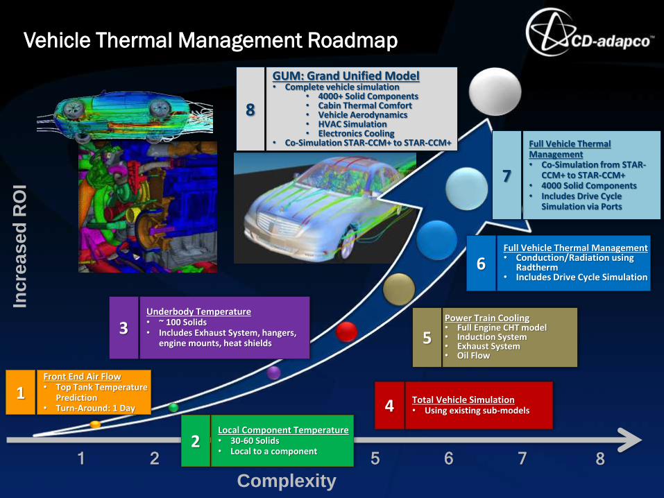
Vehicle Thermal Management Roadmap
1 2 3 4 5 6 7
Front End Air Flow • Top Tank Temperature
Prediction • Turn-Around: 1 Day
1
Local Component Temperature • 30-60 Solids • Local to a component
2
Total Vehicle Simulation • Using existing sub-models 4
Underbody Temperature • ~ 100 Solids • Includes Exhaust System, hangers,
engine mounts, heat shields
3 Power Train Cooling • Full Engine CHT model • Induction System • Exhaust System • Oil Flow
5
Full Vehicle Thermal Management • Conduction/Radiation using
Radtherm • Includes Drive Cycle Simulation
6
Full Vehicle Thermal Management • Co-Simulation from STAR-
CCM+ to STAR-CCM+ • 4000 Solid Components • Includes Drive Cycle
Simulation via Ports
7
8
GUM: Grand Unified Model • Complete vehicle simulation
• 4000+ Solid Components • Cabin Thermal Comfort • Vehicle Aerodynamics • HVAC Simulation • Electronics Cooling
• Co-Simulation STAR-CCM+ to STAR-CCM+
8
Complexity
Inc
rea
se
d R
OI

Simulation using the Digital Prototype
Durability
(BiW) Crash
NVH
Ride/Handling
HVAC/
Thermal Comfort
Durability
Chassis
Aerodynamics
Climate Control
Heat
Protection
Manufacturing
Powertrain Transmission
Digital Prototype becomes enabler
for advance simulation
– Simulation for more advance
analysis then just component design
– Simulation includes multi-physics.
– Simulation can involve motion as
needed as well. Whatever best helps
engineer design their product
efficiently.
– In the past, these would not have
been possible until hardware of the
vehicle has been produced.

Generation of a Digital Prototype
Data Freeze defines digital prototype
– As with a real prototype, design teams work
together to meet a goal for the design freeze.
– Review board checks, to make sure all
components are fitted together and data pool is
complete.
Data Filter: Filters data for simulation
– Data needed for simulation is filtered from the
overall data pool, and provided for the virtual
simulation.
• Key component for data transfer
– Example of data filters:
• Red Cedars Heeds
• Custom tool designed to pull data together.
– OpenRoad
• CAD plugin can help provide data filter
– PLM (product lifecycle management) tools
enable communication between different tools.
Analysis Response
– Feeds back into the data pool for design
improvement.
0
500
1000
1500
2000
2500
3000
0 0,1 0,2 0,3 0,4 0,5 0,6 0,7 0,8
Deflection speed v Dam
pin
g f
orc
e F
Grade 1
Grade 2
Geometrical Data Functional Data

Automation: Front End Cooling/Aerodynamics
Challenge: Data Filtering Large CAD database needs to be
quickly moved from 1000’s of CAD
parts to few boundaries needed for
CFD.
Solution: OpenRoad
• Provides part filtering with link to
boundary setup for the simulation.
• Forms template for the full
simulation process including dual
stream heat exchangers.
Impact:
• Enables users to quickly predict
drag and/or front end air flow.
• Enabler for more complex studies
such as component temperature
prediction, soiling, aero-acoustics
• Runs fully in batch: good for
optimization with Heeds
1
0
500
1000
1500
2000
2500
3000
0 0,1 0,2 0,3 0,4 0,5 0,6 0,7 0,8
Deflection speed v Dam
pin
g f
orc
e F
Grade 1
Grade 2
Geometrical Data Functional Data

Optimization: Front End Cooling/Aerodynamics
Challenge: Cooling Performance Engineers have two competing design
criteria's
• Need to provide cooling air for
engine.
• Decrease grill/bumper opening to
reduce drag
Solution: Optimization study can be done looking at
grill/bumper openings and fan size and
determine best case where both criteria's
can be satisfied. • Involves looking at drag at high speed
while cooling performance is done with
a uphill trailer tow study.
Impact:
• Using SHERPA improvements are
seen within 50 design iterations
1

System Simulation: Brake Cooling
Modeling Brake Cooling
• Thermal temperature
prediction of brake disk.
• Brake drive cycle studies
• Brake cooling duct design
• Optimization: Minimize rotor
temperature while reducing drag.
• Failure protection
• Water splash/spray on
bearings
•Dust shield design
2

System Simulation: “An Innovative Approach to Race
Track Simulations for Vehicle Thermal Management”
Challenge: Extreme drive cycle push strain on thermal
environment of the engine.
Solution: Simulation can help reduce time and
costs compared to experimental
testing.
Allows testing during early concept
phases where testing is not possible
due to lack of hardware.
Allowed simplified thermal
components to be modeled quickly in
Radtherm, coupled to a detail CFD
simulation
Impact: Improve endurance on PowerTrain.
Reduce thermal drive failures
Reduce cost and time.
18
“Overall the methodology indicated that fast quasi-transient solutions
can be achieved for a highly dynamic profile with our current
computational resources” Kristian Haehndel, BMW Group
6

System Simulation: Steady-State Full VTM Simulation
Airflow + Solids using co-simulation
• Air model is
~35 million cells.
• Solid Model is
~35 million cells.
• Over 4000 solid
components modeled
in the simulation
7

Shell Vs Solid Modeling
Accuracy
– Solids are more accurate
• Air flow imping on edge
• Heat capacity of solid
– Number of parts considered is more critical
• How many parts can be modeled in 4 weeks Turn-around time?
Recommendation
– Use what provides fastest turn-around time
– CD-adapco Goal:
• Using solid elements should provide fastest modeling and modification time since the true part has thickness
• Working at automating part contact with solid elements.
– Zero thickness can be a problem

System Simulation: Thermal Analysis & Design
Improvement of an Internal Air-Cooled Electric
Machine
Challenge: Use simulation to
improve the thermal
performance of an internal air-
cooled induction machine
Solution: Compute EM losses in
SPEED and map as heat loads to STAR-CCM+
EM Loss/Heat Loads

Battery Modelling
A Multi-Physics and Multi-Length Scales Solution
Characterizes cell
electrochemical and
physical description
Cell performance
validated against
experimental data.
Skin temperature applied to
cell, and thermal cooling
prediction is carried out with
STAR-CCM+.
Battery design studio used to determine cell performance. Cell performance
can then be supplied to surface of cell to determine packaging of battery back.

Case Studies
– Oil Slosh: Gearbox, Hydraulic Reservoir
– Gears: Planetary, Screw, Pinion ETC
– Bearings
– Clutch Plate
– Torque Converter
Operating Conditions
– Flooding
• Leakage into transmission
– Thermal Fatigue Stress
• Operating Load Point
• Heat up or Cool Down
• Drive Cycle
System Simulations: Transmission
Key Enablers:
• Overset Grids
• Robust VOF Simulation

System Simulation: Headlamps
Challenge: Two challenges
• Condensation
• Thermal deformation
Solution: Simulation of Condensation
• Investigating removal time for
condensation on/in headlamp
• Look at ventilation patterns in headlamp
Thermal Environment
• Investigating thermal stresses that may
cause deformation or melting
Impact: Improves safety and customer satisfaction.
24
“STAR-CCM+ is capable of handling conjugate heat transfer
phenomena between different bodies as well as radiation and
solid stress. ” Andrea Menotti, Olsa S.P.A

Passenger Thermal Comfort
– Thermal comfort manikin
Transient heat up/cool down modes
– Highlights importance of fast radiation
modeling
• Need Solar, diffused solar, and reflective radiation
– Experience with heat transfer through walls
and heat capacity
Deice/Defog Simulation
– Important use of wall film models
System Simulation: Cabin Comfort

System Simulations: Manufacturing
Drying
Paint Dip/E-Coat
Spray Paint
Casting

System Simulation is impacting design
– Reduce turn-around time in design
– Reduce costs from reducing number of prototypes
Simulation is expanding
– Users are looking at replacing more expensive tests with simulation
– As capability grows and mature in simulation tools, so does the demand on extending the features.
Design Exploration Growing
– With increased automation provided by the STAR-CCM+ suite, optimization expanding to provide engineers with best design, in the shortest design cycle.
Summary

Thank You!