simulation and calculation - erco · simulation and calculation light simulation and light cal...
TRANSCRIPT
376Edition: 05/12/2006 | Updated version at www.erco.com
E GuideSimulation and calculation
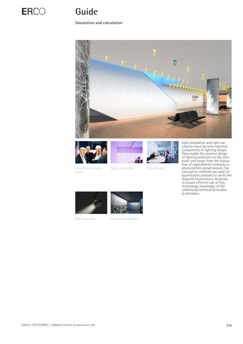
Light simulation and light calculation have become essential components of lighting design. They enable the creative design of lighting solutions on the computer and range from the evaluation of experimental concepts to photorealistic presentations. The calculation methods are used for quantitative analyses to verify the required illuminances. However, to ensure efficient use of this technology, knowledge of the underlying technical principles is necessary.
Introduction Simulation
Planning examples
CalculationsLight simulation
Planning data
377Edition: 05/12/2006 | Updated version at www.erco.com
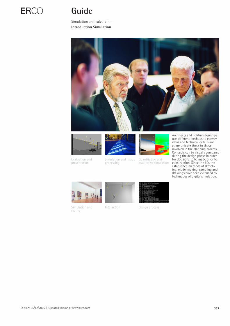
Architects and lighting designers use different methods to convey ideas and technical details and communicate these to those involved in the planning process. Concepts can be visually compared during the design phase in order for decisions to be made prior to construction. Since the 80s the established methods of sketching, model making, sampling and drawings have been extended by techniques of digital simulation.
E GuideSimulation and calculationIntroduction Simulation
Evaluation and presentation
Quantitative and qualitative simulation
Simulation and image processing
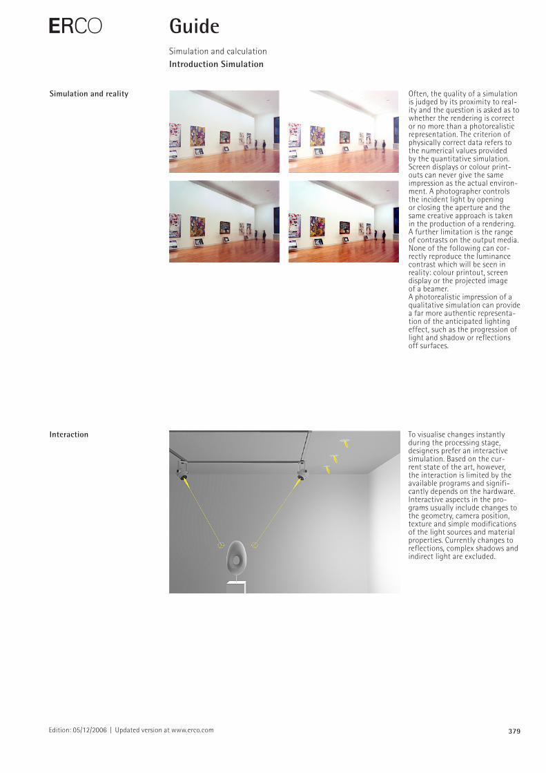
Simulation and reality
Design process Interaction
378Edition: 05/12/2006 | Updated version at www.erco.com
Evaluation and presentation Comparable to model making, the simulation also differentiates between the working model and the presentation model. While the working model simplifies the design process in that it provides rough, sketched variants, the presentation model includes elaborate details. In lighting design, sketches, digital drawings and photo realistic representations are quick visualisation methods. For further examination this is followed by general light simulation, omitting exact details of materials or luminaires. In a subsequent step, the simulation is improved by including realistic surfaces and specific luminaires with accurate photometrics for detailed planning and presentation purposes.
E GuideSimulation and calculationIntroduction Simulation
Simulation and image processing
Simulation is generally associated with 3D models and an accurate representation of the lighting effect. However, for schematic visualisations, designers often use digital image processing in a 2D or 3D representation. The advantage lies in the speed of abstraction and realisation. If the space to be illuminaited is complex then this method does not allow detailed planning due to limitations associated with scaling and complicated geometry.
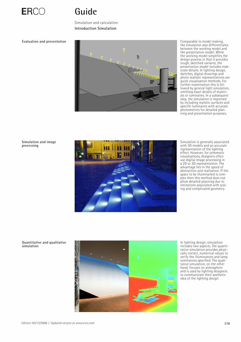
Quantitative and qualitative simulation
In lighting design, simulation includes two aspects. The quantitative simulation provides physically correct, numerical values to verify the illuminances and lamp luminances specified. The qualitative simulation, on the other hand, focuses on atmosphere and is used by lighting designers to communicate their aesthetic idea of the lighting design.
379Edition: 05/12/2006 | Updated version at www.erco.com
E GuideSimulation and calculationIntroduction Simulation
Simulation and reality Often, the quality of a simulation is judged by its proximity to reality and the question is asked as to whether the rendering is correct or no more than a photorealistic representation. The criterion of physically correct data refers to the numerical values provided by the quantitative simulation. Screen displays or colour printouts can never give the same impression as the actual environment. A photographer controls the incident light by opening or closing the aperture and the same creative approach is taken in the production of a rendering. A further limitation is the range of contrasts on the output media. None of the following can correctly reproduce the luminance contrast which will be seen in reality: colour printout, screen display or the projected image of a beamer.A photorealistic impression of a qualitative simulation can provide a far more authentic representation of the anticipated lighting effect, such as the progression of light and shadow or reflections off surfaces.
Interaction To visualise changes instantly during the processing stage, designers prefer an interactive simulation. Based on the current state of the art, however, the interaction is limited by the available programs and significantly depends on the hardware. Interactive aspects in the programs usually include changes to the geometry, camera position, texture and simple modifications of the light sources and material properties. Currently changes to reflections, complex shadows and indirect light are excluded.
380Edition: 05/12/2006 | Updated version at www.erco.com
E GuideSimulation and calculationIntroduction Simulation
Design process A crucial factor in ensuring an efficient light simulation during the design process is a reasonable degree of detailing and the assistance of an expert. Time and cost can be controlled by limiting the scope of the presentation. The implementation of the light simulation can either be handled by the design office itself or outsourced to a specialist provider. If handled internally, a rendering can be prepared in conjunction with the design process. Simulations, on the other hand, using an external service provider involve considerable information exchange. This is compensated for by the fact that the service provider has greater experience, can produce quicker results and this can lead to reducing the cost for the design.The sequence of a light simulation can be divided into four steps: the modelling of the geometry, the definition of materials, the illumination of the model, and the actual rendering process.
381Edition: 03/01/2010 | Updated version at www.erco.com
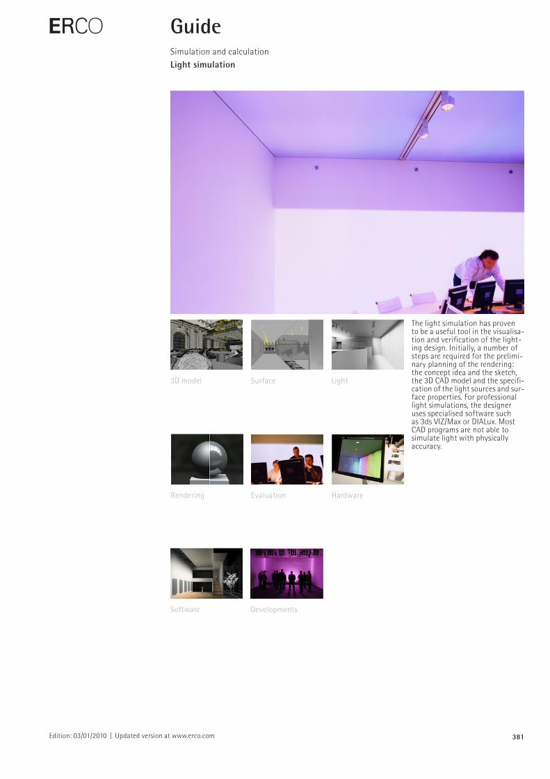
The light simulation has proven to be a useful tool in the visuali sation and verification of the lighting design. Initially, a number of steps are required for the preliminary planning of the rendering: the concept idea and the sketch, the 3D CAD model and the specification of the light sources and surface properties. For professional light simulations, the designer uses specialised software such as 3ds VIZ/Max or DIALux. Most CAD programs are not able to simulate light with physically accuracy.
E GuideSimulation and calculationLight simulation
3D model LightSurface
Rendering HardwareEvaluation
Software Developments
382Edition: 03/01/2010 | Updated version at www.erco.com
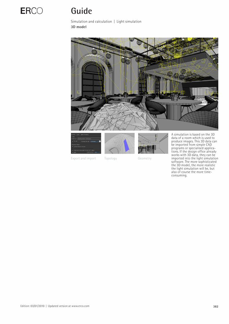
A simulation is based on the 3D data of a room which is used to produce images. This 3D data can be imported from simple CAD programs or specialised applications. If the design office already works with 3D data, they can be imported into the light simulation software. The more sophisticated the 3D model, the more realistic the light simulation will be, but also of course the more timeconsuming.
E GuideSimulation and calculation | Light simulation3D model
Export and import GeometryTopology
383Edition: 03/01/2010 | Updated version at www.erco.com
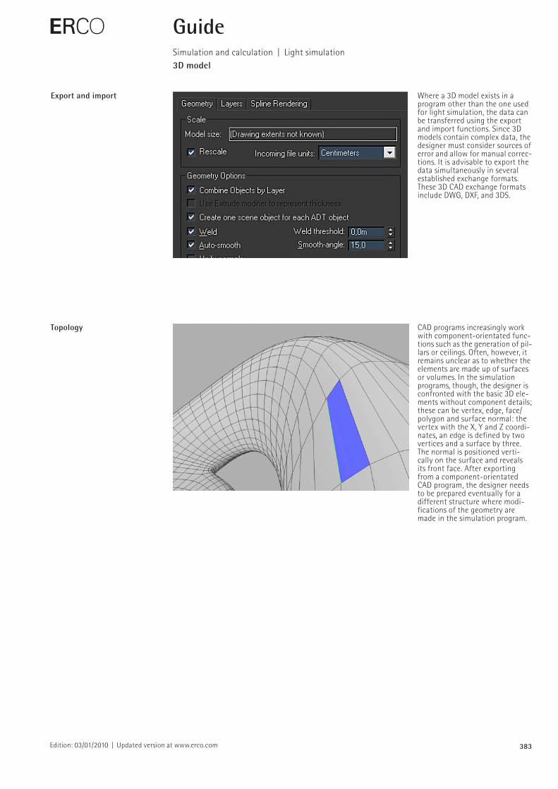
Export and import Where a 3D model exists in a program other than the one used for light simulation, the data can be transferred using the export and import functions. Since 3D models contain complex data, the designer must consider sources of error and allow for manual corrections. It is advisable to export the data simultaneously in several established exchange formats. These 3D CAD exchange formats include DWG, DXF, and 3DS.
E
Topology CAD programs increasingly work with componentorientated func tions such as the generation of pillars or ceilings. Often, however, it remains unclear as to whether the elements are made up of surfaces or volumes. In the simulation programs, though, the designer is confronted with the basic 3D elements without component details; these can be vertex, edge, face/polygon and surface normal: the vertex with the X, Y and Z coordinates, an edge is defined by two vertices and a surface by three. The normal is positioned verti cally on the surface and reveals its front face. After exporting from a componentorientated CAD program, the designer needs to be prepared eventually for a different structure where modifications of the geometry are made in the simulation program.
GuideSimulation and calculation | Light simulation3D model
384Edition: 03/01/2010 | Updated version at www.erco.com
E
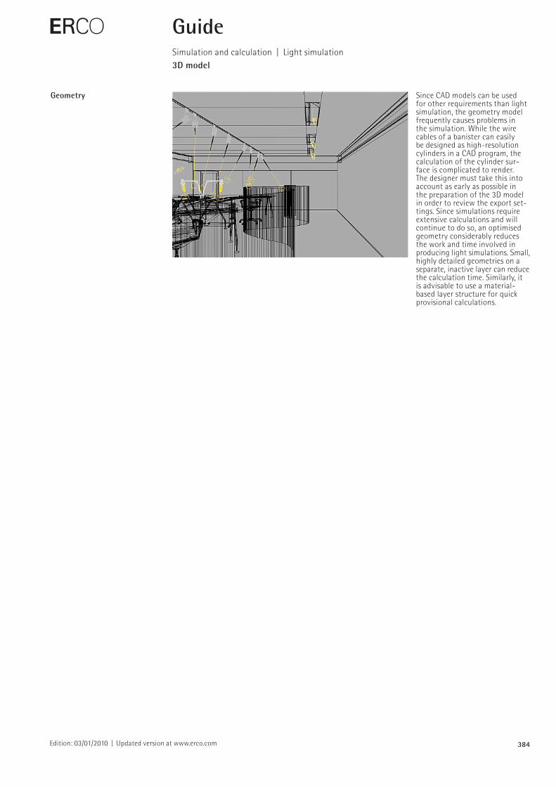
Geometry Since CAD models can be used for other requirements than light simulation, the geometry model frequently causes problems in the simulation. While the wire cables of a banister can easily be designed as highresolution cylinders in a CAD program, the calculation of the cylinder surface is complicated to render. The designer must take this into account as early as possible in the preparation of the 3D model in order to review the export settings. Since simulations require extensive calculations and will continue to do so, an optimised geometry considerably reduces the work and time involved in producing light simulations. Small, highly detailed geometries on a separate, inactive layer can reduce the calculation time. Similarly, it is advisable to use a materialbased layer structure for quick provisional calculations.
GuideSimulation and calculation | Light simulation3D model
385Edition: 03/01/2010 | Updated version at www.erco.com
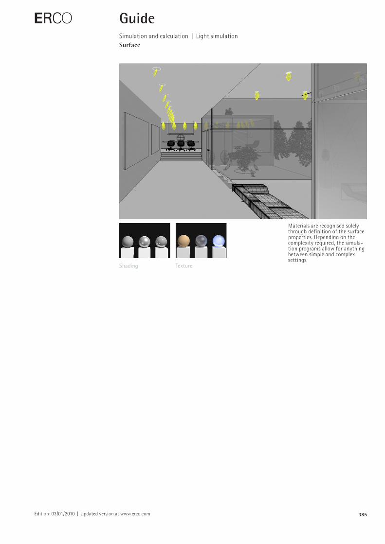
Materials are recognised solely through definition of the surface properties. Depending on the complexity required, the simulation programs allow for anything between simple and complex settings.
E GuideSimulation and calculation | Light simulationSurface
Shading Texture
386Edition: 03/01/2010 | Updated version at www.erco.com
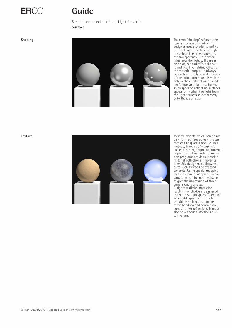
Shading The term ”shading” refers to the representation of shades. The designer uses a shader to define the lighting properties through the colour, the reflectance and the transparency. These determine how the light will appear on an object and affect the surroundings. The lighting effect of the material properties always depends on the type and position of the light sources and is visible only in the combination of shading factors and lighting: hence, shiny spots on reflecting surfaces appear only when the light from the light sources shines directly onto these surfaces.
E GuideSimulation and calculation | Light simulationSurface
Texture To show objects which don‘t have a uniform surface colour, the surface can be given a texture. This method, known as "mapping“, places abstract, graphical patterns or photos on the model. Simulation programs provide extensive material collections in libraries to enable designers to show textures such as wood or exposed concrete. Using special mapping methods (bump mapping), microstructures can be modified so as to give the impression of threedimensional surfaces.A highly realistic impression results if by photos are assigned as textures to polygons. To ensure acceptable quality, the photo should be high resolution, be taken headon and contain no light or other reflections. It must also be without distortions due to the lens.
387Edition: 03/01/2010 | Updated version at www.erco.com
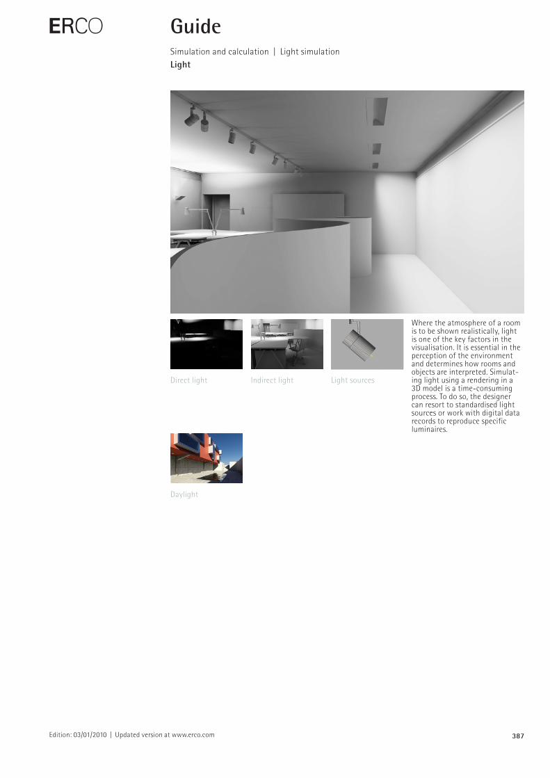
Where the atmosphere of a room is to be shown realistically, light is one of the key factors in the visualisation. It is essential in the perception of the environment and determines how rooms and objects are interpreted. Simulating light using a rendering in a 3D model is a timeconsuming process. To do so, the designer can resort to standardised light sources or work with digital data records to reproduce specific luminaires.
E GuideSimulation and calculation | Light simulationLight
Direct light Indirect light Light sources
Daylight
388Edition: 03/01/2010 | Updated version at www.erco.com
E GuideSimulation and calculation | Light simulationLight
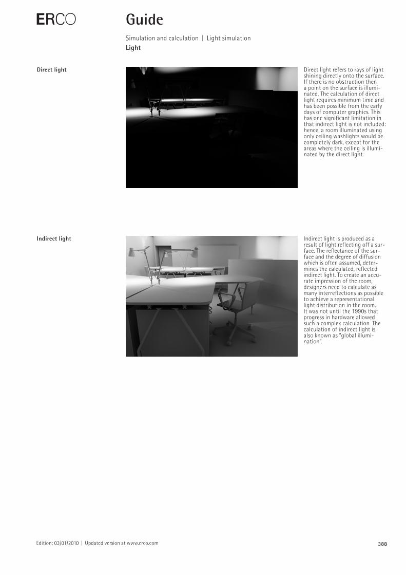
Direct light Direct light refers to rays of light shining directly onto the surface. If there is no obstruction then a point on the surface is illuminated. The calculation of direct light requires minimum time and has been possible from the early days of computer graphics. This has one significant limitation in that indirect light is not included: hence, a room illuminated using only ceiling washlights would be completely dark, except for the areas where the ceiling is illuminated by the direct light.
Indirect light Indirect light is produced as a result of light reflecting off a sur face. The reflectance of the surface and the degree of diffusion which is often assumed, determines the calculated, reflected indirect light. To create an accurate impression of the room, designers need to calculate as many interreflections as possible to achieve a representational light distribution in the room. It was not until the 1990s that progress in hardware allowed such a complex calculation. The calculation of indirect light is also known as ”global illumination”.
389Edition: 03/01/2010 | Updated version at www.erco.com
Light sourcesLight distribution
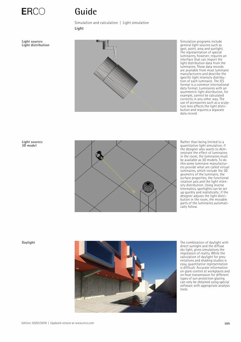
Simulation programs include general light sources such as spot, point, area and sunlight. The representation of special luminaires, however, requires an interface that can import the light distribution data from the luminaires. These data records are available from most luminaire manufacturers and describe the specific light intensity distribution of each luminaire. The IES format is a common international data format. Luminaires with an asymmetric light distribution, for example, cannot be calculated correctly in any other way. The use of accessories such as a sculpture lens affects the light distribution and requires a separate data record.
Daylight The combination of daylight with direct sunlight and the diffuse sky light, gives simulations the impression of reality. While the calculation of daylight for presentations and shading studies is easy, quantitative representation is difficult. Accurate information on glare control at workplaces and on heat transmission for different types of sun protection glazing can only be obtained using special software with appropriate analysis tools.
E GuideSimulation and calculation | Light simulationLight
Light sources3D model
Rather than being limited to a quantitative light simulation, if the designer also wants to demonstrate the effect of luminaires in the room, the luminaires must be available as 3D models. To do this some luminaire manufacturers provide what are called virtual luminaires, which include the 3D geometry of the luminaire, the surface properties, the functional rotation axis and the light intensity distribution. Using inverse kinematics, spotlights can be set up quickly and realistically: if the designer adjusts the light distribution in the room, the movable parts of the luminaires automatically follow.
390Edition: 03/01/2010 | Updated version at www.erco.com
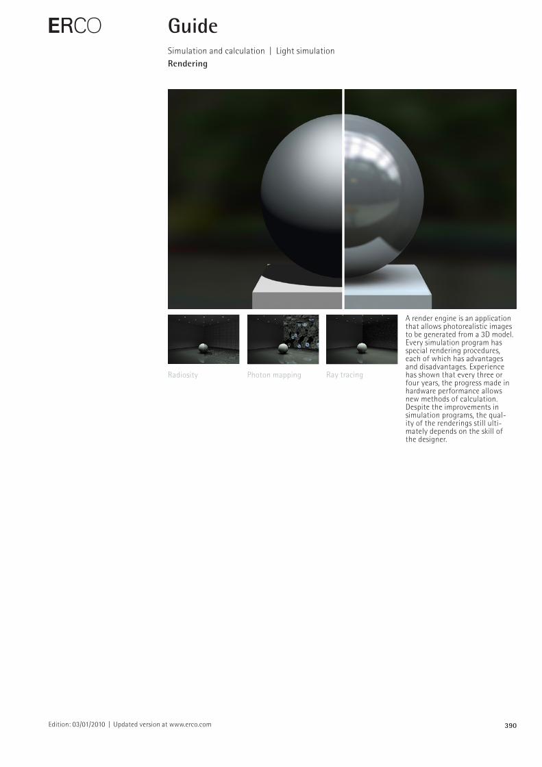
A render engine is an application that allows photorealistic images to be generated from a 3D model. Every simulation program has special rendering procedures, each of which has advantages and disadvantages. Experience has shown that every three or four years, the progress made in hardware performance allows new methods of calculation. Despite the improvements in simulation programs, the qual ity of the renderings still ultimately depends on the skill of the designer.
E GuideSimulation and calculation | Light simulationRendering
Radiosity Photon mapping Ray tracing
391Edition: 03/01/2010 | Updated version at www.erco.com
E GuideSimulation and calculation | Light simulationRendering
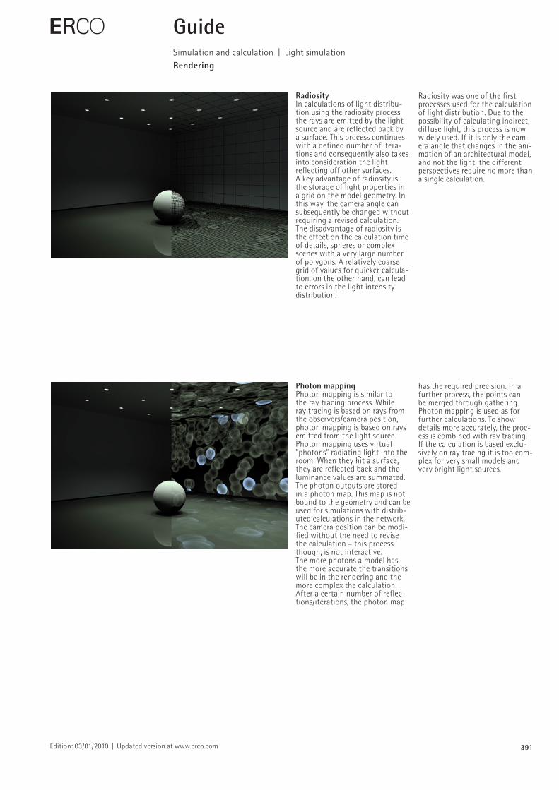
RadiosityIn calculations of light distribution using the radiosity process the rays are emitted by the light source and are reflected back by a surface. This process continues with a defined number of iterations and consequently also takes into consideration the light reflecting off other surfaces.A key advantage of radiosity is the storage of light properties in a grid on the model geometry. In this way, the camera angle can subsequently be changed without requiring a revised calculation.The disadvantage of radiosity is the effect on the calculation time of details, spheres or complex scenes with a very large number of polygons. A relatively coarse grid of values for quicker calculation, on the other hand, can lead to errors in the light intensity distribution.
Photon mapping Photon mapping is similar to the ray tracing process. While ray tracing is based on rays from the observers/camera position, photon mapping is based on rays emitted from the light source. Photon mapping uses virtual ”photons” radiating light into the room. When they hit a surface, they are reflected back and the luminance values are summated. The photon outputs are stored in a photon map. This map is not bound to the geometry and can be used for simulations with distributed calculations in the network. The camera position can be modified without the need to revise the calculation – this process, though, is not interactive.The more photons a model has, the more accurate the transitions will be in the rendering and the more complex the calculation. After a certain number of reflections/iterations, the photon map
Radiosity was one of the first processes used for the calculation of light distribution. Due to the possibility of calculating indirect, diffuse light, this process is now widely used. If it is only the camera angle that changes in the animation of an architectural model, and not the light, the different perspectives require no more than a single calculation.
has the required precision. In a further process, the points can be merged through gathering.Photon mapping is used as for further calculations. To show details more accurately, the process is combined with ray tracing. If the calculation is based exclusively on ray tracing it is too complex for very small models and very bright light sources.
392Edition: 03/01/2010 | Updated version at www.erco.com
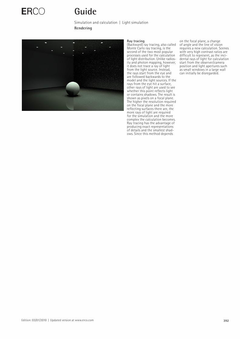
Ray tracing (Backward) ray tracing, also called Monte Carlo ray tracing, is the second of the two most popular processes used for the calculation of light distribution. Unlike radiosity and photon mapping, however, it does not trace a ray of light from the light source. Instead, the rays start from the eye and are followed backwards to the model and the light sources. If the rays from the eye hit a surface, other rays of light are used to see whether this point reflects light or contains shadows. The result is shown as pixels on a focal plane. The higher the resolution required on the focal plane and the more reflecting surfaces there are, the more rays of light are required for the simulation and the more complex the calculation becomes.Ray tracing has the advantage of producing exact representations of details and the smallest shadows. Since this method depends
E GuideSimulation and calculation | Light simulationRendering
on the focal plane, a change of angle and the line of vision requires a new calculation. Scenes with very high contrast ratios are difficult to represent, as the incidental rays of light for calculation start from the observer/camera position and light apertures such as small windows in a large wall can initially be disregarded.
393Edition: 03/01/2010 | Updated version at www.erco.com
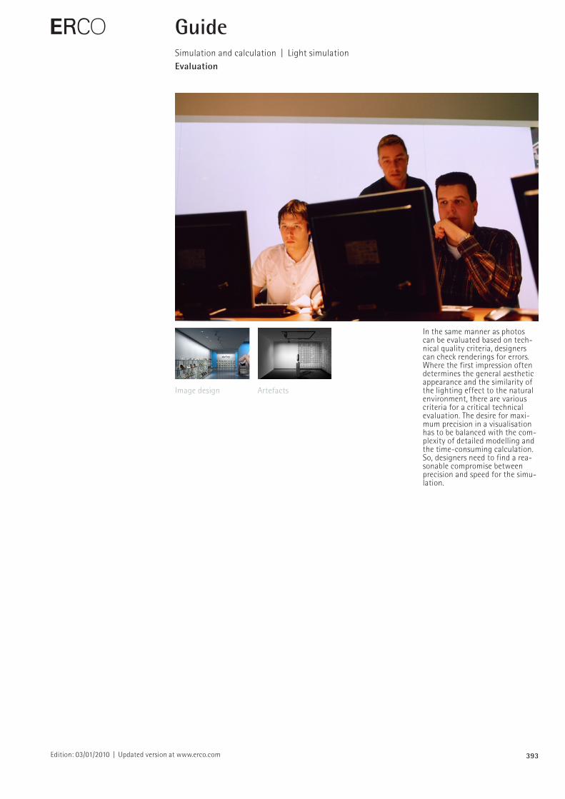
In the same manner as photos can be evaluated based on technical quality criteria, designers can check renderings for errors. Where the first impression often determines the general aesthetic appearance and the similarity of the lighting effect to the natural environment, there are various criteria for a critical technical evaluation. The desire for maximum precision in a visualisation has to be balanced with the com plexity of detailed modelling and the timeconsuming calculation. So, designers need to find a reasonable compromise between precision and speed for the simulation.
E GuideSimulation and calculation | Light simulationEvaluation
Image design Artefacts
394Edition: 03/01/2010 | Updated version at www.erco.com
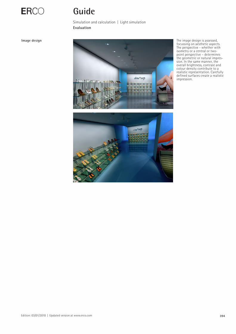
Image design The image design is assessed, focussing on aesthetic aspects. The perspective whether with isometry or a central or two point perspective – determines the geometric or natural impression. In the same manner, the overall brightness, contrast and colour density contribute to a realistic representation. Carefully defined surfaces create a realistic impression.
E GuideSimulation and calculation | Light simulationEvaluation
395Edition: 03/01/2010 | Updated version at www.erco.com
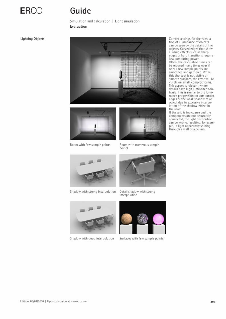
Lighting Objects Correct settings for the calculation of illuminance of objects can be seen by the details of the objects. Curved edges that show aliasing effects such as sharp edges or hard transitions require less computing power.Often, the calculation times can be reduced many times over if only a few sample points are smoothed and gathered. While this shortcut is not visible on smooth surfaces, the error will be visible on small, complex forms. This aspect is relevant where details have high luminance contrasts. This is similar to the luminance progression on component edges or the weak shadow of an object due to excessive interpolation of the shadoweffect in the room.If the grid is too coarse and the components are not accurately connected, the light distribution can be wrong, resulting, for example, in light apparently shining through a wall or a ceiling.
E GuideSimulation and calculation | Light simulationEvaluation
Room with few sample points Room with numerous sample points
Shadow with strong interpolation Detail shadow with strong interpolation
Shadow with good interpolation Surfaces with few sample points
396Edition: 03/01/2010 | Updated version at www.erco.com
E GuideSimulation and calculation | Light simulationHardware
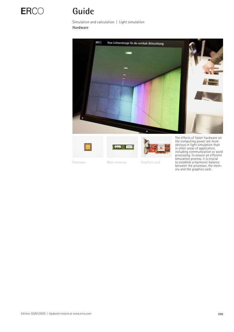
The effects of faster hardware on the computing power are more obvious in light simulation than in other areas of application, including communication or word processing. To ensure an efficient simulation process, it is crucial to establish a harmonic balance between the processor, the memory and the graphics card.
Processor Main memory Graphics card
397Edition: 03/01/2010 | Updated version at www.erco.com
E GuideSimulation and calculation | Light simulationHardware
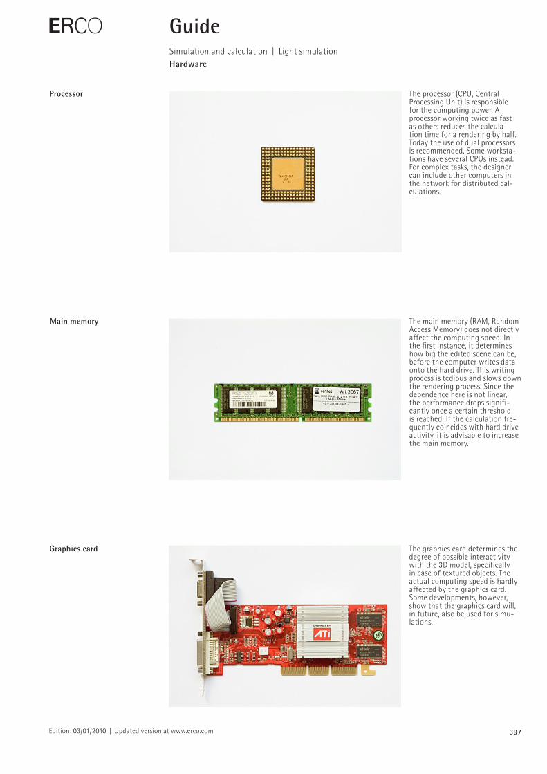
Processor The processor (CPU, Central Processing Unit) is responsible for the computing power. A processor working twice as fast as others reduces the calculation time for a rendering by half. Today the use of dual processors is recommended. Some workstations have several CPUs instead. For complex tasks, the designer can include other computers in the network for distributed calculations.
Main memory The main memory (RAM, Random Access Memory) does not directly affect the computing speed. In the first instance, it determines how big the edited scene can be, before the computer writes data onto the hard drive. This writing process is tedious and slows down the rendering process. Since the dependence here is not linear, the performance drops significantly once a certain threshold is reached. If the calculation frequently coincides with hard drive activity, it is advisable to increase the main memory.
Graphics card The graphics card determines the degree of possible interactivity with the 3D model, specifically in case of textured objects. The actual computing speed is hardly affected by the graphics card. Some developments, however, show that the graphics card will, in future, also be used for simulations.
398Edition: 03/01/2010 | Updated version at www.erco.com
E GuideSimulation and calculation | Light simulationSoftware
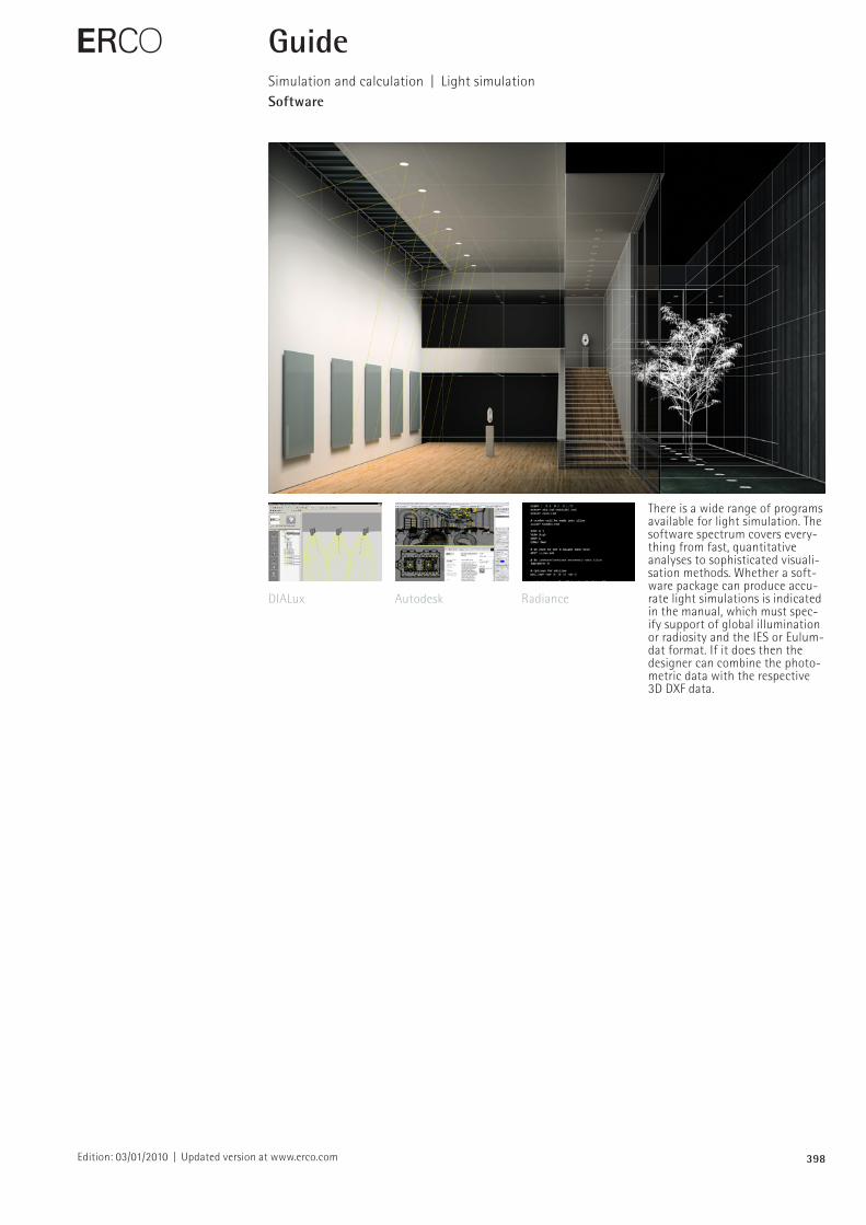
There is a wide range of programs available for light simulation. The software spectrum covers everything from fast, quantitative analyses to sophisticated visualisation methods. Whether a soft ware package can produce accu rate light simulations is indicated in the manual, which must specify support of global illumination or radiosity and the IES or Eulumdat format. If it does then the designer can combine the photometric data with the respective 3D DXF data.
DIALux Autodesk Radiance
399Edition: 03/01/2010 | Updated version at www.erco.com
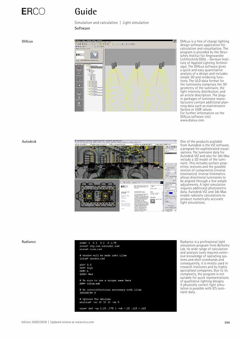
DIALux DIALux is a free of charge lighting design software application for calculation and visualisation. The program is provided by the Deutsches Institut für Angewandte Lichttechnik (DIAL – German Institute of Applied Lighting Technology). The DIALux software gives a quick and easy quantitative analysis of a design and includes simple 3D and rendering functions. The ULD data format for the luminaires comprises the 3D geometry of the luminaire, the light intensity distribution, and an article description. The plug in packages of luminaire manufacturers contain additional planning data such as maintenance factors or UGR values.For further information on the DIALux software visit www.dialux.com.
Autodesk One of the products available from Autodesk is the VIZ software, a program for sophisticated visualisations. The luminaire data for Autodesk VIZ and also for 3ds Max include a 3D model of the luminaire. This includes surface properties, textures and the possible motion of components (inverse kinematics). Inverse kinematics allows directional luminaires to be aligned through a few simple adjustments. A light simulation requires additional photometric data. Autodesk VIZ and 3ds Max enable radiosity calculations to produce numerically accurate light simulations.
Radiance Radiance is a professional light simulation program from Berkeley Lab. Its wide range of calculation and analysis tools requires extensive knowledge of operating sys tems and shell commands and consequently, it is mostly used in research institutes and by highly specialised companies. Due to its complexity, the program is not suitable for quick representations of qualitative lighting designs. A physically correct light simulation is possible with IES luminaire data.
E GuideSimulation and calculation | Light simulationSoftware
400
100
80
60
20
0
40
800
%
400 500 700600 nm300
Edition: 03/01/2010 | Updated version at www.erco.com
E GuideSimulation and calculation | Light simulationDevelopments
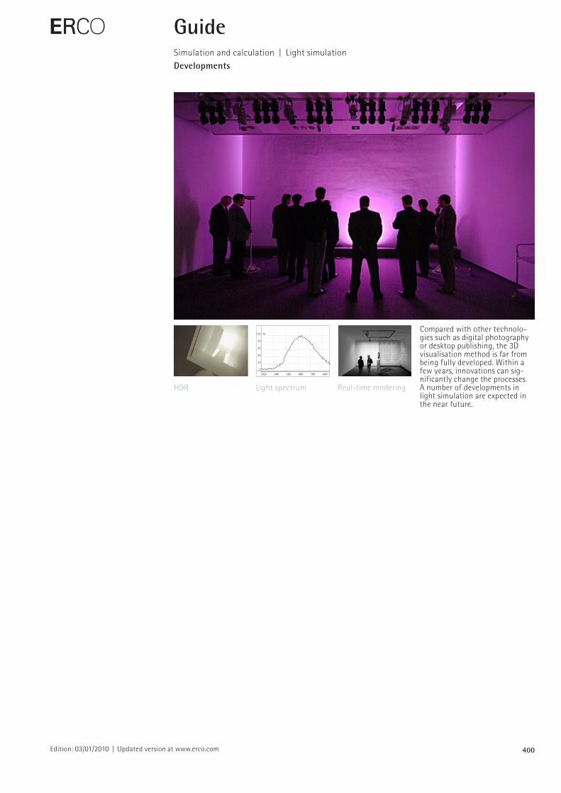
Compared with other technologies such as digital photography or desktop publishing, the 3D visualisation method is far from being fully developed. Within a few years, innovations can significantly change the processes. A number of developments in light simulation are expected in the near future.
HDR Light spectrum Realtime rendering
401
100
80
60
20
0
40
800
%
400 500 700600 nm300
%100
80
60
20
0
40
800400 500 700600 nm300
Edition: 03/01/2010 | Updated version at www.erco.com
E GuideSimulation and calculation | Light simulationDevelopments
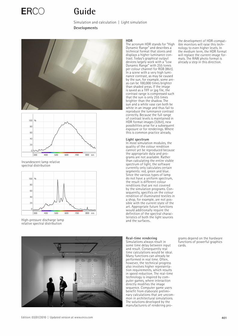
HDRThe acronym HDR stands for “High Dynamic Range“ and describes a technical format that stores and displays a higher luminance contrast. Today’s graphical output devices largely work with a “Low Dynamic Range” with 255 tones per colour channel for RGB (8bit). In a scene with a very high luminance contrast, as may be caused by the sun, for example, some areas can be 100,000 times brighter than shaded areas. If the image is saved as a TIFF or jpg file, the contrast range is compressed such that the sun is only 255 times brighter than the shadow. The sun and a white vase can both be white in an image and thus fail to reproduce the luminance contrast correctly. Because the full range of contrast levels is maintained in HDR format images (32bit), new possibilities arise for a subsequent exposure or for renderings. Where this is common practice already,
Light spectrum In most simulation modules, the quality of the colour rendition cannot yet be reproduced because the appropriate data and programs are not available. Rather than calculating the entire visible spectrum of light, the software currently only calculates certain segments: red, green and blue. Since the various types of lamp do not have a uniform spectrum, the result is different colour renditions that are not covered by the simulation programs. Consequently, specifics on the colour rendition of illuminated textiles in a shop, for example, are not possible with the current state of the art. Appropriate future functions would additionally require the definition of the spectral characteristics of both the light sources and the surfaces..
Real-time rendering Simulations always result in some time delay between input and result. Consequently real time calculations would be ideal. Many functions can already be performed in real time. Often, however, the technical progress also involves higher representation requirements, which results in speed reduction. The realtime technology is inspired by computer games, where interaction directly modifies the image sequence. Computer game users benefit from elaborate preliminary calculations that are uncommon in architectural simulations. The solutions developed by the manufacturers of rendering pro
grams depend on the hardware functions of powerful graphics cards.
the development of HDRcompatible monitors will raise this technology to even higher levels. In the medium term, the HDR format will replace the current image for mats. The RAW photo format is already a step in this direction.
Incandescent lamp relative spectral distribution
Highpressure discharge lamp relative spectral distribution
402Edition: 20/02/2012 | Updated version at www.erco.com
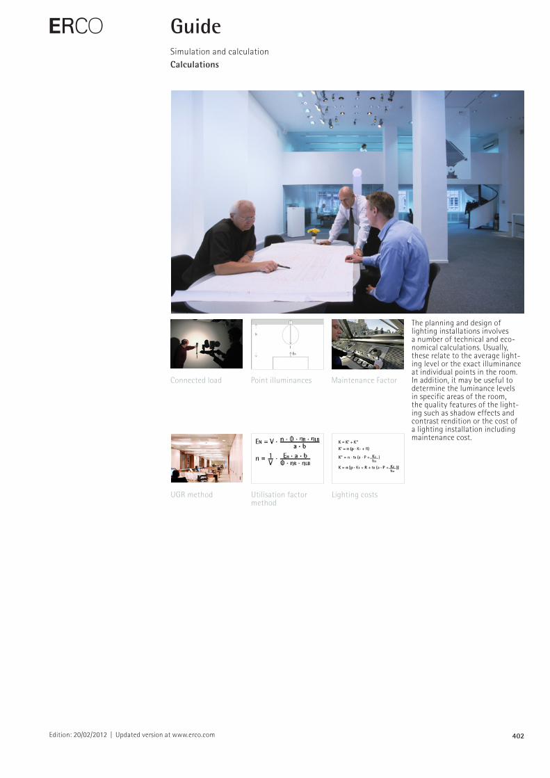
The planning and design of lighting installations involves a number of technical and economical calculations. Usually, these relate to the average lighting level or the exact illuminance at individual points in the room. In addition, it may be useful to determine the luminance levels in specific areas of the room, the quality features of the lighting such as shadow effects and contrast rendition or the cost of a lighting installation including maintenance cost.
E GuideSimulation and calculationCalculations
Connected load Maintenance Factor Point illuminances
UGR method Lighting costs Utilisation factor method
403Edition: 20/02/2012 | Updated version at www.erco.com
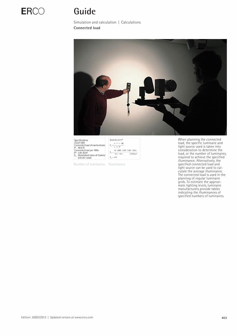
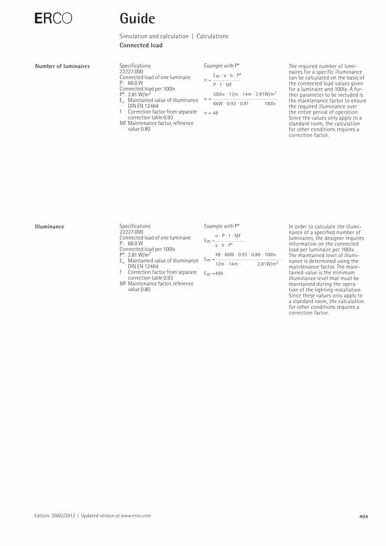
When planning the connected load, the specific luminaire and light source used is taken into consideration to determine the load, or the number of luminaires, required to achieve the specified illuminance. Alternatively, the specified connected load and light source can be used to calculate the average illuminance. The connected load is used in the planning of regular luminaire grids. To estimate the approximate lighting levels, luminaire manufacturers provide tables indicating the illuminances of specified numbers of luminaires.
E GuideSimulation and calculation | CalculationsConnected load
Number of luminaires Illuminance
404
Specifications 22227.000 Connected load of one luminaire P: 66.0 WConnected load per 100lxP*: 2.81 W/m2
Em Maintained value of illuminance DIN EN 12464
f Correction factor from separate correction table 0.93
MF Maintenance factor, reference value 0.80
Example with P*
Em · a · b · P*n = P · f · MF
500lx · 12m · 14m · 2.81W/m2
n = 66W · 0.93 · 0.81 · 100lx
n = 48
Specifications 22227.000 Connected load of one luminaire P: 66.0 WConnected load per 100lxP*: 2.81 W/m2
Em Maintained value of illuminance DIN EN 12464
f Correction factor from separate correction table 0.93
MF Maintenance factor, reference value 0.80
Example with P*
n · P · f · MFEm = a · b · P*
48 · 66W · 0.93 · 0.80 · 100lxEm = 12m · 14m · 2.81W/m2
Em =499
Edition: 20/02/2012 | Updated version at www.erco.com
Number of luminaires The required number of luminaires for a specific illuminance can be calculated on the basis of the connected load values given for a luminaire and 100lx. A further parameter to be included is the maintenance factor to ensure the required illuminance over the entire period of operation. Since the values only apply to a standard room, the calculation for other conditions requires a correction factor.
E
Illuminance In order to calculate the illuminance of a specified number of luminaires, the designer requires information on the connected load per luminaire per 100lx. The maintained level of illuminance is determined using the maintenance factor. The maintained value is the minimum illuminance level that must be maintained during the operation of the lighting installation. Since these values only apply to a standard room, the calculation for other conditions requires a correction factor.
GuideSimulation and calculation | CalculationsConnected load
405Edition: 20/02/2012 | Updated version at www.erco.com
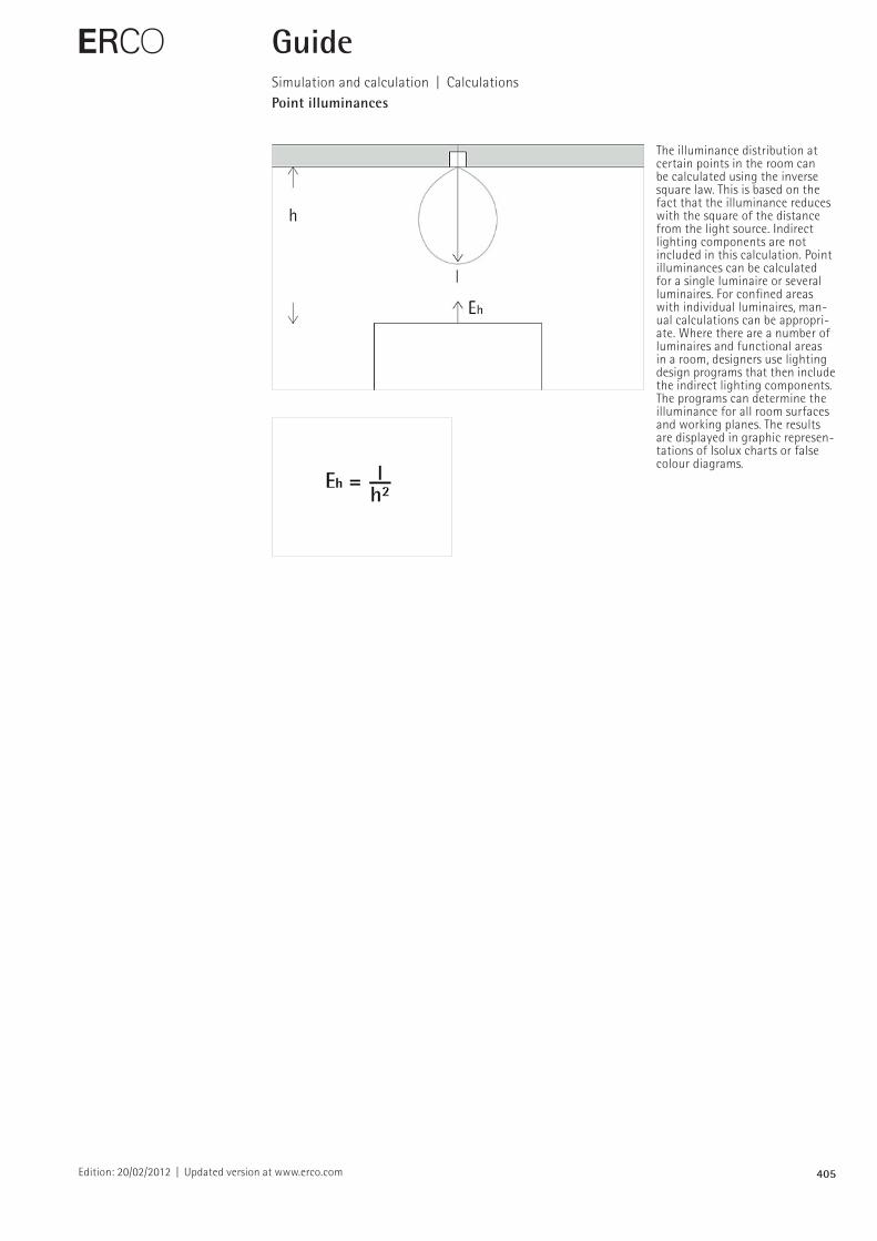
The illuminance distribution at certain points in the room can be calculated using the inverse square law. This is based on the fact that the illuminance reduces with the square of the distance from the light source. Indirect lighting components are not included in this calculation. Point illuminances can be calculated for a single luminaire or several luminaires. For confined areas with individual luminaires, manual calculations can be appropriate. Where there are a number of luminaires and functional areas in a room, designers use lighting design programs that then include the indirect lighting components. The programs can determine the illuminance for all room surfaces and working planes. The results are displayed in graphic representations of Isolux charts or false colour diagrams.
E GuideSimulation and calculation | CalculationsPoint illuminances
406Edition: 20/02/2012 | Updated version at www.erco.com
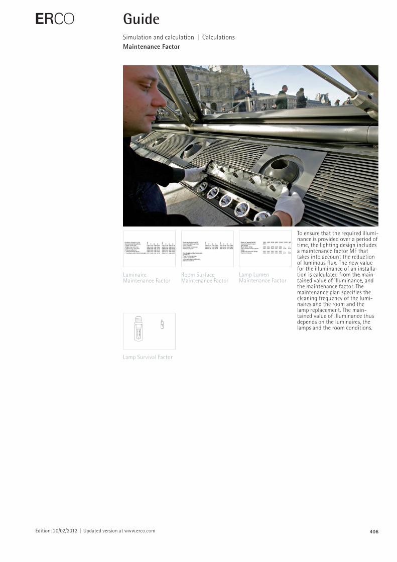
To ensure that the required illuminance is provided over a period of time, the lighting design includes a maintenance factor MF that takes into account the reduction of luminous flux. The new value for the illuminance of an installation is calculated from the main tained value of illuminance, and the maintenance factor. The maintenance plan specifies the cleaning frequency of the luminaires and the room and the lamp replacement. The maintained value of illuminance thus depends on the luminaires, the lamps and the room conditions.
Luminaire Maintenance Factor
Room Surface Maintenance Factor
E GuideSimulation and calculation | CalculationsMaintenance Factor
Lamp Lumen Maintenance Factor
Lamp Survival Factor
407
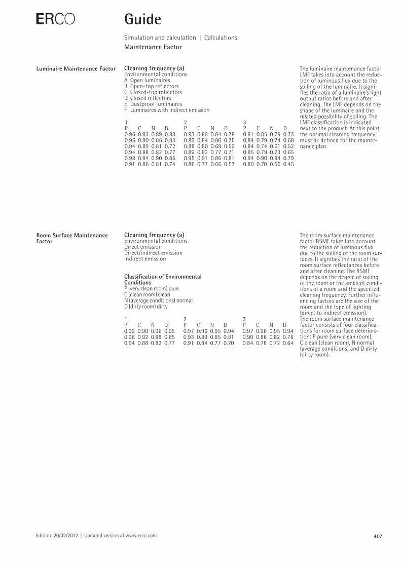
Cleaning frequency (a)Environmental conditionsA Open luminairesB Opentop reflectorsC Closedtop reflectors D Closed reflectors E Dustproof luminairesF Luminaires with indirect emission
1 2 3P C N D P C N D P C N D0.96 0.93 0.89 0.83 0.93 0.89 0.84 0.78 0.91 0.85 0.79 0.730.96 0.90 0.86 0.83 0.89 0.84 0.80 0.75 0.84 0.79 0.74 0.680.94 0.89 0.81 0.72 0.88 0.80 0.69 0.59 0.84 0.74 0.61 0.520.94 0.88 0.82 0.77 0.89 0.83 0.77 0.71 0.85 0.79 0.73 0.650.98 0.94 0.90 0.86 0.95 0.91 0.86 0.81 0.94 0.90 0.84 0.790.91 0.86 0.81 0.74 0.86 0.77 0.66 0.57 0.80 0.70 0.55 0.45
1 2 3P C N D P C N D P C N D0.99 0.98 0.96 0.95 0.97 0.96 0.95 0.94 0.97 0.96 0.95 0.940.96 0.92 0.88 0.85 0.93 0.89 0.85 0.81 0.90 0.86 0.82 0.780.94 0.88 0.82 0.77 0.91 0.84 0.77 0.70 0.84 0.78 0.72 0.64
Classification of Environmental ConditionsP (very clean room) pureC (clean room) cleanN (average conditions) normalD (dirty room) dirty
Cleaning frequency (a)Environmental conditionsDirect emissionDirect/indirect emission Indirect emission
Edition: 20/02/2012 | Updated version at www.erco.com
Luminaire Maintenance Factor The luminaire maintenance factor LMF takes into account the reduction of luminous flux due to the soiling of the luminaire. It signifies the ratio of a luminaire’s light output ratios before and after cleaning. The LMF depends on the shape of the luminaire and the related possibility of soiling. The LMF classification is indicated next to the product. At this point, the optimal cleaning frequency must be defined for the maintenance plan.
Room Surface Maintenance Factor
The room surface maintenance factor RSMF takes into account the reduction of luminous flux due to the soiling of the room surfaces. It signifies the ratio of the room surface reflectances before and after cleaning. The RSMF depends on the degree of soiling of the room or the ambient conditions of a room and the specified cleaning frequency. Further influencing factors are the size of the room and the type of lighting (direct to indirect emission).The room surface maintenance factor consists of four classifications for room surface deterioration: P pure (very clean room), C clean (clean room), N normal (average conditions) and D dirty (dirty room).
E GuideSimulation and calculation | CalculationsMaintenance Factor
408
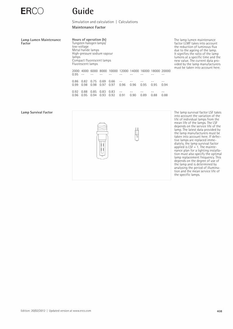
2000 4000 6000 8000 10000 12000 14000 16000 18000 200000.95
0.86 0.82 0.75 0.69 0.66 0.99 0.98 0.98 0.97 0.97 0.96 0.96 0.95 0.95 0.94
0.92 0.88 0.85 0.83 0.83 0.96 0.95 0.94 0.93 0.92 0.91 0.90 0.89 0.88 0.88
Hours of operation (h)Tungsten halogen lamps/ lowvoltageMetal halide lamps Highpressure sodium vapour lampsCompact fluorescent lamps Fluorescent lamps
Edition: 20/02/2012 | Updated version at www.erco.com
Lamp Lumen Maintenance Factor
The lamp lumen maintenance factor LLMF takes into account the reduction of luminous flux due to the ageing of the lamp. It signifies the ratio of the lamp lumens at a specific time and the new value. The current data provided by the lamp manufacturers must be taken into account here.
E GuideSimulation and calculation | CalculationsMaintenance Factor
Lamp Survival Factor The lamp survival factor LSF takes into account the variation of the life of individual lamps from the mean life of the lamps. The LSF depends on the service life of the lamp. The latest data provided by the lamp manufacturers must be taken into account here. If defective lamps are replaced immediately, the lamp survival factor applied is LSF = 1. The maintenance plan for a lighting installation must also specify the optimal lamp replacement frequency. This depends on the degree of use of the lamp and is determined by analysing the period of illumination and the mean service life of the specific lamps.
409
3.3 Practical planning3.3.6 Calculations
the portion of luminous flux emitted bythe light sources, which falls on theworking plane after interaction with lumi-naires and room surfaces. The decidingfactor in this calculation is the utilance,which is derived from the geometry ofthe space, the reflectance of the room sur-faces and the efficiency and the distri-bution characteristics of the luminairesused.
To be able to calculate the appropriateutilance in each individual case, there are tables available, which contain theutilance of a standardised space withchanging room geometry, changing re-flection factors and luminaires with avariety of distribution characteristics. Thebasic, idealised space is presumed to beempty and of regular shape and propor-tions, i.e. rectangular and having the ratioof length to width approx. 1.6 to 1. The luminaires are presumed to be arrangedin a regular pattern on the ceiling, eithermounted directly onto the ceiling or sus-pended from the ceiling. These standar-dised values have a decisive influence onthe accuracy of the calculations for theapplication. If the conditions inherent inthe basic concept are in line with those inthe model space, the results will be rea-sonably accurate. The more the basic con-ditions deviate from the standardisedconditions, e.g. if the lighting layout is distinctly asymmetrical, it must be acceptedthat an increasing number of errors willoccur in the calculation.
When using the utilisation factor method an appropriate utilance table hasto be used for each type of luminaire. Thecorresponding standard luminaire classifi-cation table can be used for this purpose.Luminaire classification in accordancewith DIN 5040 and the German LightingEngineering Society is made up of oneletter and two digits, a combination indi-cates a number of luminaire qualities. The letter defines the luminaire class andindicates whether a luminaire emits light primarily in the upper or lower partof the space, i.e. direct or indirect ligh-ting. The first digit refers to the proportionof luminous flux falling onto the workingplane in the lower part of the space. Thesecond digit indicates the correspondingvalue for the upper part of the space. It isoften not necessary to use the standardtable of luminaire classification, as exacttables are supplied by the lighting manu-facturers.
155
Light output ratio hLB:ratio of the luminousflux emitted by a lumi-nair ÏLe under opera-ting conditions to theluminous flux of thelamp ÏLa.
Utilisation factor method: formula forcalculating the nominal illuminance EN for a given number of lumi-naires or the numberof luminaires n for a given illuminance.
Typical light output ratios hLB for direct luminaires with variouscut-off angles and lamp types.
Luminaire Lamp type hLB
Louvred luminaire 30° T26 0.65–0.75Louvred luminaire 40° T26 0.55–0.65Louvred lumin. square TC 0.50–0.70Downlight 30° TC 0.60–0.70Downlight 40° TC 0.50–0.60Downlight 30° A/QT 0.70–0.75Downlight 40° A/QT 0.60–0.70
EN (lx) Nominal illuminancen Number of luminairesa (m) Length of spaceb (m) Width of spaceÏ (m) Luminous flux per luminairehR UtilancehLB Light output ratioV Light loss factor
ÏLa
ÏLe
æLB = ÏLeÏLa
EN = V . n . Ï . æR . æLBa . b
n = . En . a . bÏ . æR . æLB
1V
Edition: 20/02/2012 | Updated version at www.erco.com
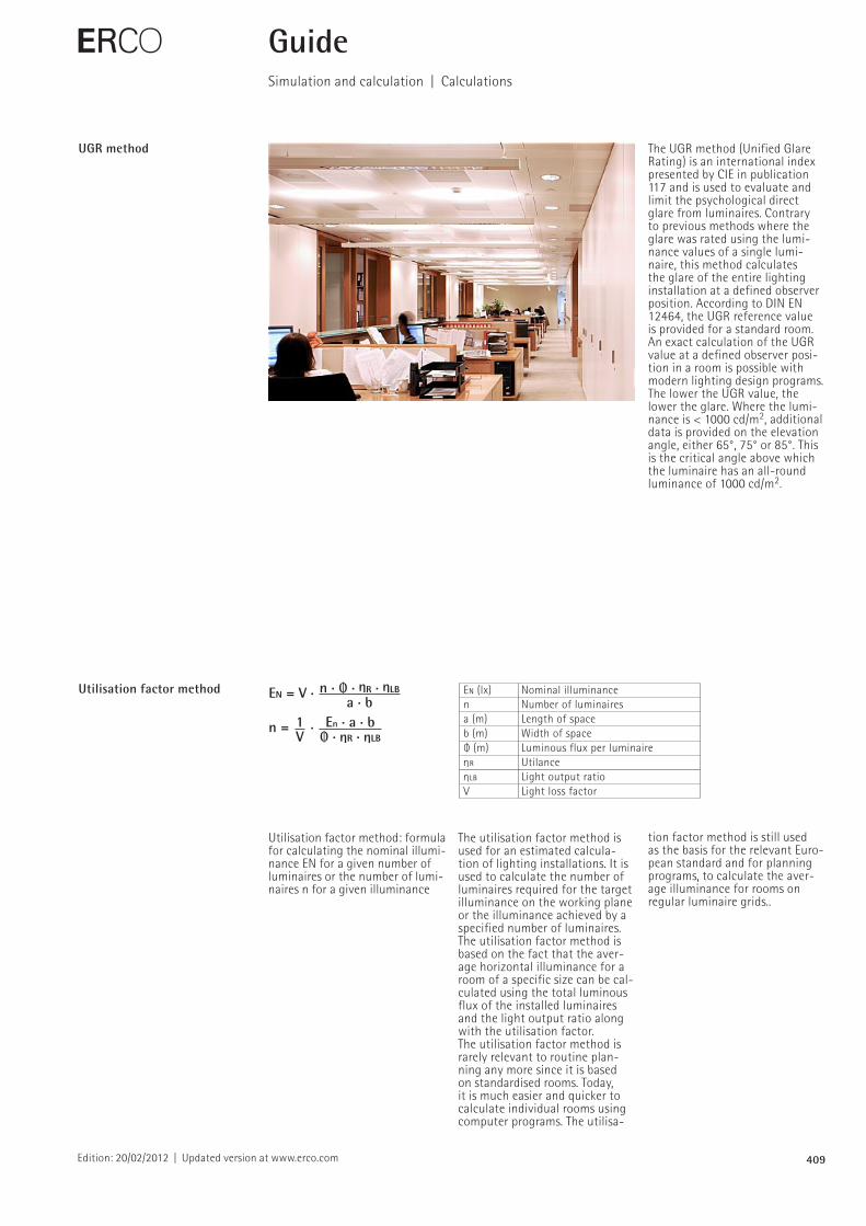
The UGR method (Unified Glare Rating) is an international index presented by CIE in publication 117 and is used to evaluate and limit the psychological direct glare from luminaires. Contrary to previous methods where the glare was rated using the luminance values of a single luminaire, this method calculates the glare of the entire lighting installation at a defined observer position. According to DIN EN 12464, the UGR reference value is provided for a standard room. An exact calculation of the UGR value at a defined observer position in a room is possible with modern lighting design programs. The lower the UGR value, the lower the glare. Where the luminance is < 1000 cd/m2, additional data is provided on the elevation angle, either 65°, 75° or 85°. This is the critical angle above which the luminaire has an allround luminance of 1000 cd/m2.
E GuideSimulation and calculation | Calculations
UGR method
The utilisation factor method is used for an estimated calculation of lighting installations. It is used to calculate the number of luminaires required for the target illuminance on the working plane or the illuminance achieved by a specified number of luminaires. The utilisation factor method is based on the fact that the average horizontal illuminance for a room of a specific size can be calculated using the total luminous flux of the installed luminaires and the light output ratio along with the utilisation factor.The utilisation factor method is rarely relevant to routine planning any more since it is based on standardised rooms. Today, it is much easier and quicker to calculate individual rooms using computer programs. The utilisa
Utilisation factor method
Utilisation factor method: formula for calculating the nominal illuminance EN for a given number of luminaires or the number of luminaires n for a given illuminance
tion factor method is still used as the basis for the relevant Euro pean standard and for planning programs, to calculate the average illuminance for rooms on regular luminaire grids..
410
Eh
P
A L
™
h
Eh
P
L
å
Ev
Eh
3.3 Practical planning3.3.6 Calculations
3.3.6.4 Lighting costs
When calculating the costs for a lightinginstallation it is necessary to differentiatebetween the fixed costs and the variablecosts. The fixed costs do not apply to theoperating time of the lighting installation,they comprise the amotised costs for the luminaires, for their installation andcleaning. The variable costs are dependenton the operating time. They comprise costsfor energy, material and wages for staffcarrying out lamp replacement. On thebasis of these values it is possible to cal-culate the different qualities of a lightinginstallation.
The annual costs of a lighting instal-lation are of particular interest. It is oftenadvisable to compare the economic effi-ciency of different lamp types in the plan-ning phase. This data can be calculatedeither as annual costs or as costs for theproduction of a specific quantity of light.The pay-back time is important in bothcompletely new projects and refurbishmentprojects, that is to say the period of timewithin which the operating costs that havebeen saved can be set off against theinvestment costs for the new installation.
159
Horizontal illuminanceEh at point P, producedby luminous surface Aof luminance L at angle ™.
Horizontal illuminanceEh at point P, producedby a circular luminoussurface of luminance L,whereby the surfaceextends to an angle 2 å.
Vertical illumnancee Ev,produced by luminanceL from one half of thespace.
Horizontal illuminanceEh, produced by lumi-nance L from one halfof the space.
Formula for calculatingthe costs of a lightinginstallation K from thefixed costs K' and theannual operating costsK".
Formula for calculatingthe pay-back time t of a new installation.
Comparison of thepay-back time t of twonew installations, whereby installation Bhas higher investmentcosts and lower opera-ting costs.
Calculating illumi-nances from the lumi-nance of flat lightsources.
a (EU/kWh) Energy costs K (EU/a) Annual costs for a
lighting installationK' (EU/a) Fixed annual costsK" (EU/a) Annual operating costsK1 (EU) Costs per luminaire incl. mountingK2 (EU) Costs per lamp
incl. lamp replacementK l (EU) Investment costs (n · K1)
n Number of luminairesp (1/a) Interest payments for the installa-
tion (0.1–0.15)P (kW) Wattage per luminaireR (EU/a) Annual cleaning costs
per luminairet (a) Pay-back timetB (h) Annual operating timetLa (h) Service life of a lamp
Eh = . cos4 ™L . Ah2
Eh = π . L . sin2 å
[E] = lx[l] = cd/m2
[h] = m[A] = m2
K = K' + K''
K' = n (p . K1 + R)
K'' = n . tB (a . P + )K2tLa
K = n [p . K1 + R + tB (a . P + )]K2tLa
t = Kl (new)K'' (old) – K'' (new)
t = Kl (B) – Kl (A)K'' (A) – K'' (B)
Eh = π . L EV = . Lπ2
Eh
P
A L
™
h
Eh
P
L
å
Ev
Eh
3.3 Practical planning3.3.6 Calculations
3.3.6.4 Lighting costs
When calculating the costs for a lightinginstallation it is necessary to differentiatebetween the fixed costs and the variablecosts. The fixed costs do not apply to theoperating time of the lighting installation,they comprise the amotised costs for the luminaires, for their installation andcleaning. The variable costs are dependenton the operating time. They comprise costsfor energy, material and wages for staffcarrying out lamp replacement. On thebasis of these values it is possible to cal-culate the different qualities of a lightinginstallation.
The annual costs of a lighting instal-lation are of particular interest. It is oftenadvisable to compare the economic effi-ciency of different lamp types in the plan-ning phase. This data can be calculatedeither as annual costs or as costs for theproduction of a specific quantity of light.The pay-back time is important in bothcompletely new projects and refurbishmentprojects, that is to say the period of timewithin which the operating costs that havebeen saved can be set off against theinvestment costs for the new installation.
159
Horizontal illuminanceEh at point P, producedby luminous surface Aof luminance L at angle ™.
Horizontal illuminanceEh at point P, producedby a circular luminoussurface of luminance L,whereby the surfaceextends to an angle 2 å.
Vertical illumnancee Ev,produced by luminanceL from one half of thespace.
Horizontal illuminanceEh, produced by lumi-nance L from one halfof the space.
Formula for calculatingthe costs of a lightinginstallation K from thefixed costs K' and theannual operating costsK".
Formula for calculatingthe pay-back time t of a new installation.
Comparison of thepay-back time t of twonew installations, whereby installation Bhas higher investmentcosts and lower opera-ting costs.
Calculating illumi-nances from the lumi-nance of flat lightsources.
a (EU/kWh) Energy costs K (EU/a) Annual costs for a
lighting installationK' (EU/a) Fixed annual costsK" (EU/a) Annual operating costsK1 (EU) Costs per luminaire incl. mountingK2 (EU) Costs per lamp
incl. lamp replacementK l (EU) Investment costs (n · K1)
n Number of luminairesp (1/a) Interest payments for the installa-
tion (0.1–0.15)P (kW) Wattage per luminaireR (EU/a) Annual cleaning costs
per luminairet (a) Pay-back timetB (h) Annual operating timetLa (h) Service life of a lamp
Eh = . cos4 ™L . Ah2
Eh = π . L . sin2 å
[E] = lx[l] = cd/m2
[h] = m[A] = m2
K = K' + K''
K' = n (p . K1 + R)
K'' = n . tB (a . P + )K2tLa
K = n [p . K1 + R + tB (a . P + )]K2tLa
t = Kl (new)K'' (old) – K'' (new)
t = Kl (B) – Kl (A)K'' (A) – K'' (B)
Eh = π . L EV = . Lπ2
Edition: 20/02/2012 | Updated version at www.erco.com
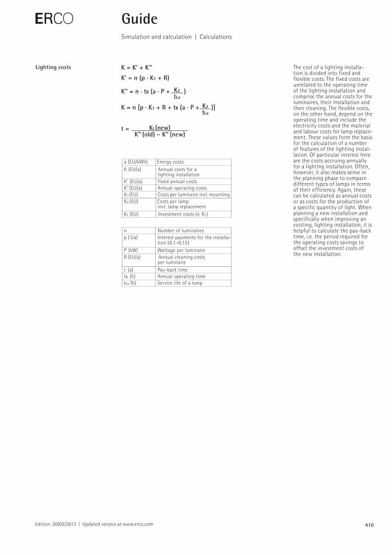
The cost of a lighting installation is divided into fixed and flexible costs. The fixed costs are unrelated to the operating time of the lighting installation and comprise the annual costs for the luminaires, their installation and their cleaning. The flexible costs, on the other hand, depend on the operating time and include the electricity costs and the material and labour costs for lamp replacement. These values form the basis for the calculation of a number of features of the lighting installation. Of particular interest here are the costs accruing annually for a lighting installation. Often, however, it also makes sense in the planning phase to compare different types of lamps in terms of their efficiency. Again, these can be calculated as annual costs or as costs for the production of a specific quantity of light. When planning a new installation and specifically when improving an existing, lighting installation, it is helpful to calculate the payback time, i.e. the period required for the operating costs savings to offset the investment costs of the new installation.
E GuideSimulation and calculation | Calculations
Lighting costs
411Edition: 20/02/2012 | Updated version at www.erco.com
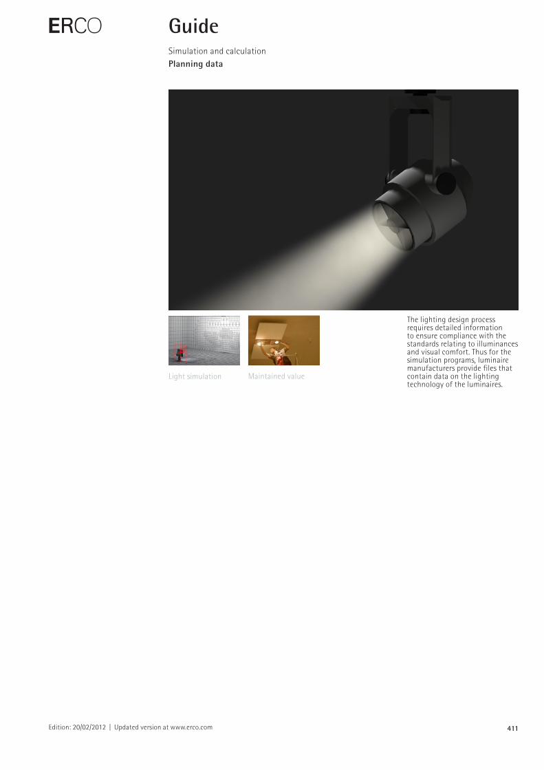
The lighting design process requires detailed information to ensure compliance with the standards relating to illuminances and visual comfort. Thus for the simulation programs, luminaire manufacturers provide files that contain data on the lighting technology of the luminaires.
E GuideSimulation and calculationPlanning data
Light simulation Maintained value
412Edition: 20/02/2012 | Updated version at www.erco.com
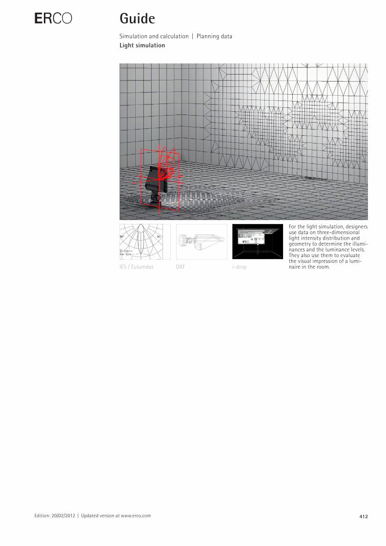
For the light simulation, designers use data on threedimensional light intensity distribution and geometry to determine the illuminances and the luminance levels. They also use them to evaluate the visual impression of a luminaire in the room.
E GuideSimulation and calculation | Planning dataLight simulation
IES / Eulumdat DXF idrop
413Edition: 20/02/2012 | Updated version at www.erco.com
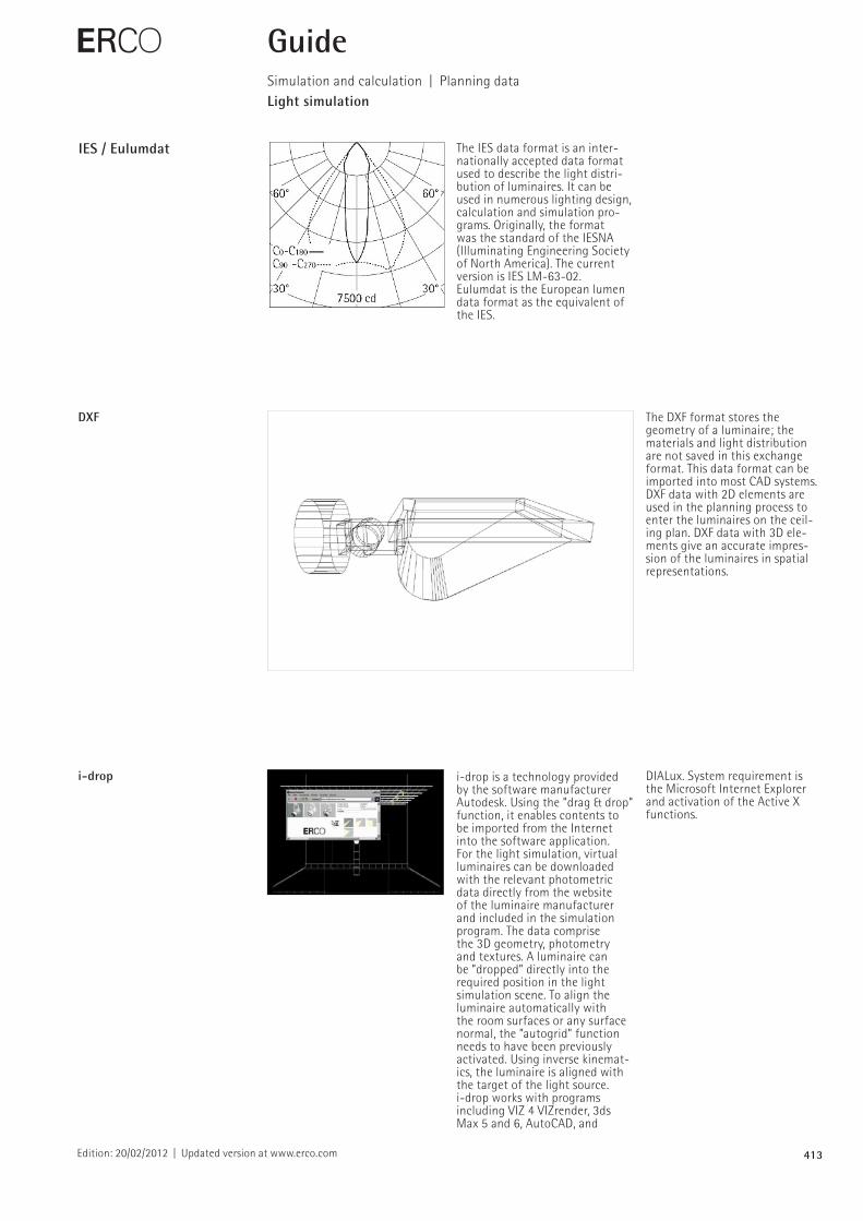
IES / Eulumdat The IES data format is an internationally accepted data format used to describe the light distribution of luminaires. It can be used in numerous lighting design, calculation and simulation programs. Originally, the format was the standard of the IESNA (Illuminating Engineering Society of North America). The current version is IES LM6302.Eulumdat is the European lumen data format as the equivalent of the IES.
E
DXF The DXF format stores the geometry of a luminaire; the materials and light distribution are not saved in this exchange format. This data format can be imported into most CAD systems. DXF data with 2D elements are used in the planning process to enter the luminaires on the ceiling plan. DXF data with 3D elements give an accurate impression of the luminaires in spatial representations.
GuideSimulation and calculation | Planning dataLight simulation
i-drop idrop is a technology provided by the software manufacturer Autodesk. Using the ”drag & drop” function, it enables contents to be imported from the Internet into the software application. For the light simulation, virtual luminaires can be downloaded with the relevant photometric data directly from the website of the luminaire manufacturer and included in the simulation program. The data comprise the 3D geometry, photometry and textures. A luminaire can be ”dropped” directly into the required position in the light simulation scene. To align the luminaire automatically with the room surfaces or any surface normal, the ”autogrid” function needs to have been previously activated. Using inverse kinematics, the luminaire is aligned with the target of the light source.idrop works with programs including VIZ 4 VIZrender, 3ds Max 5 and 6, AutoCAD, and
DIALux. System requirement is the Microsoft Internet Explorer and activation of the Active X functions.
414Edition: 20/02/2012 | Updated version at www.erco.com
E GuideSimulation and calculation | Planning dataMaintained value
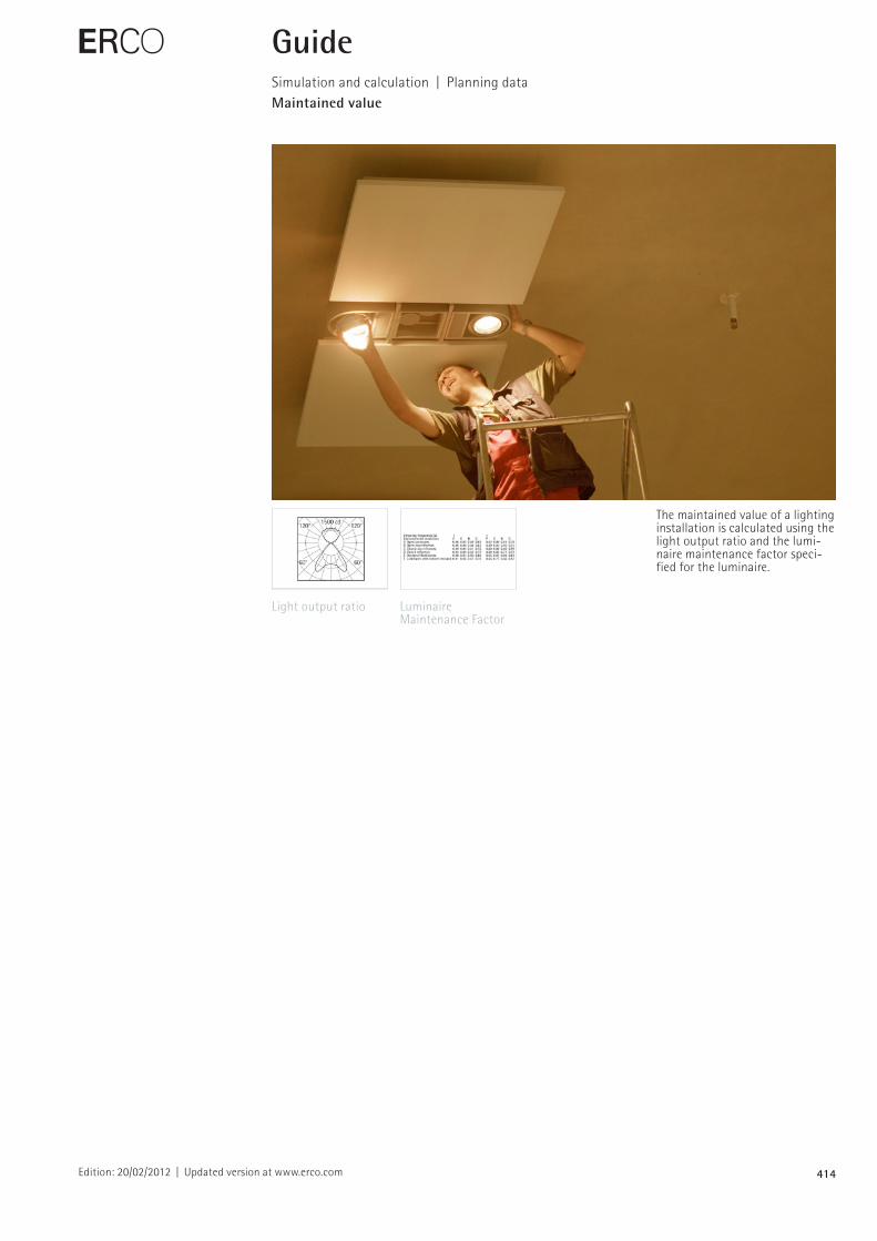
The maintained value of a lighting installation is calculated using the light output ratio and the luminaire maintenance factor specified for the luminaire.
Light output ratio Luminaire Maintenance Factor
415
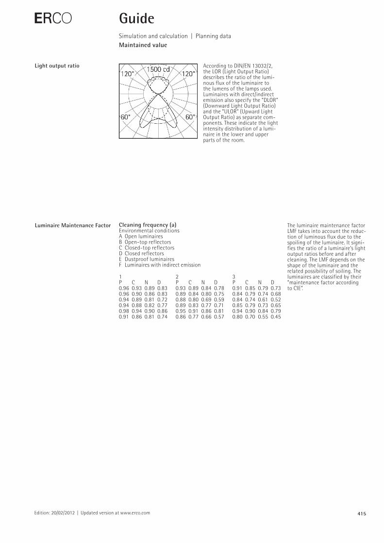
Cleaning frequency (a)Environmental conditionsA Open luminairesB Opentop reflectorsC Closedtop reflectors D Closed reflectors E Dustproof luminairesF Luminaires with indirect emission
1 2 3P C N D P C N D P C N D0.96 0.93 0.89 0.83 0.93 0.89 0.84 0.78 0.91 0.85 0.79 0.730.96 0.90 0.86 0.83 0.89 0.84 0.80 0.75 0.84 0.79 0.74 0.680.94 0.89 0.81 0.72 0.88 0.80 0.69 0.59 0.84 0.74 0.61 0.520.94 0.88 0.82 0.77 0.89 0.83 0.77 0.71 0.85 0.79 0.73 0.650.98 0.94 0.90 0.86 0.95 0.91 0.86 0.81 0.94 0.90 0.84 0.790.91 0.86 0.81 0.74 0.86 0.77 0.66 0.57 0.80 0.70 0.55 0.45
Edition: 20/02/2012 | Updated version at www.erco.com
E GuideSimulation and calculation | Planning dataMaintained value
Light output ratio According to DIN/EN 13032/2, the LOR (Light Output Ratio) describes the ratio of the luminous flux of the luminaire to the lumens of the lamps used. Luminaires with direct/indirect emission also specify the ”DLOR” (Downward Light Output Ratio) and the ”ULOR” (Upward Light Output Ratio) as separate components. These indicate the light intensity distribution of a luminaire in the lower and upper parts of the room.
Luminaire Maintenance Factor The luminaire maintenance factor LMF takes into account the reduc tion of luminous flux due to the spoiling of the luminaire. It signi fies the ratio of a luminaire’s light output ratios before and after cleaning. The LMF depends on the shape of the luminaire and the related possibility of soiling. The luminaires are classified by their ”maintenance factor according to CIE”.
416Edition: 04/01/2007 | Updated version at www.erco.com
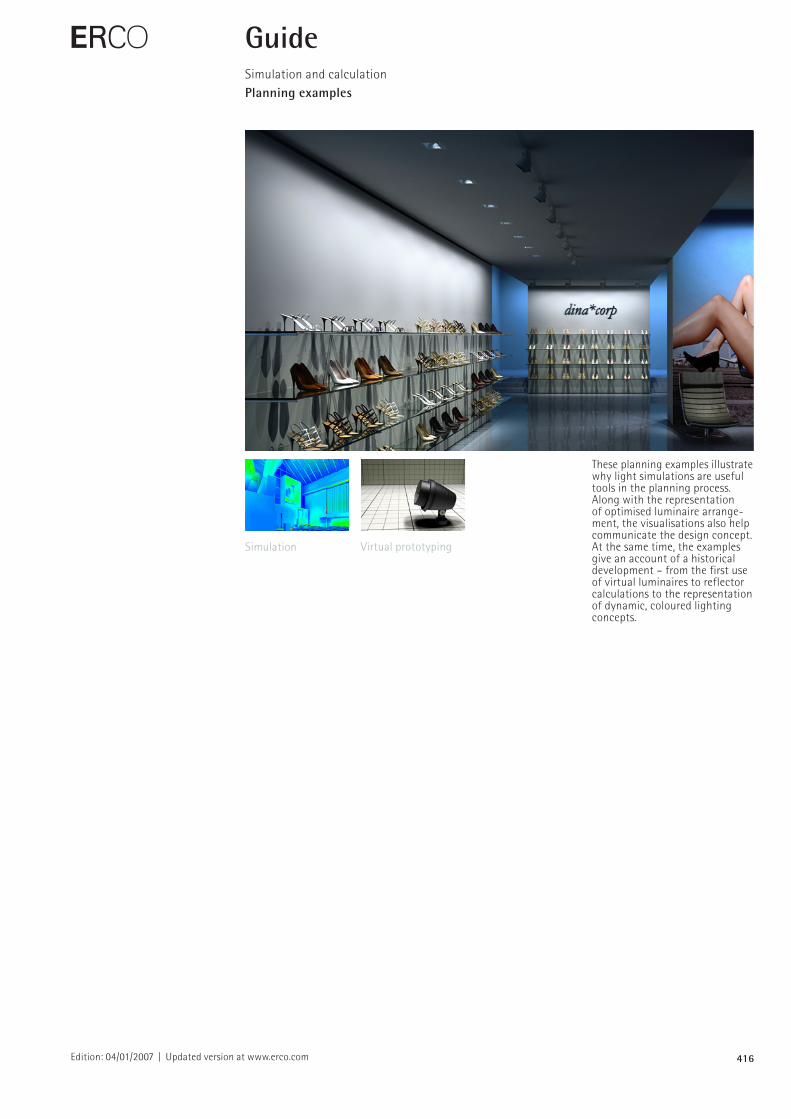
These planning examples illustrate why light simulations are useful tools in the planning process. Along with the representation of optimised luminaire arrangement, the visualisations also help communicate the design concept. At the same time, the examples give an account of a historical development – from the first use of virtual luminaires to reflector calculations to the representation of dynamic, coloured lighting concepts.
E GuideSimulation and calculationPlanning examples
Simulation Virtual prototyping
417Edition: 04/01/2007 | Updated version at www.erco.com
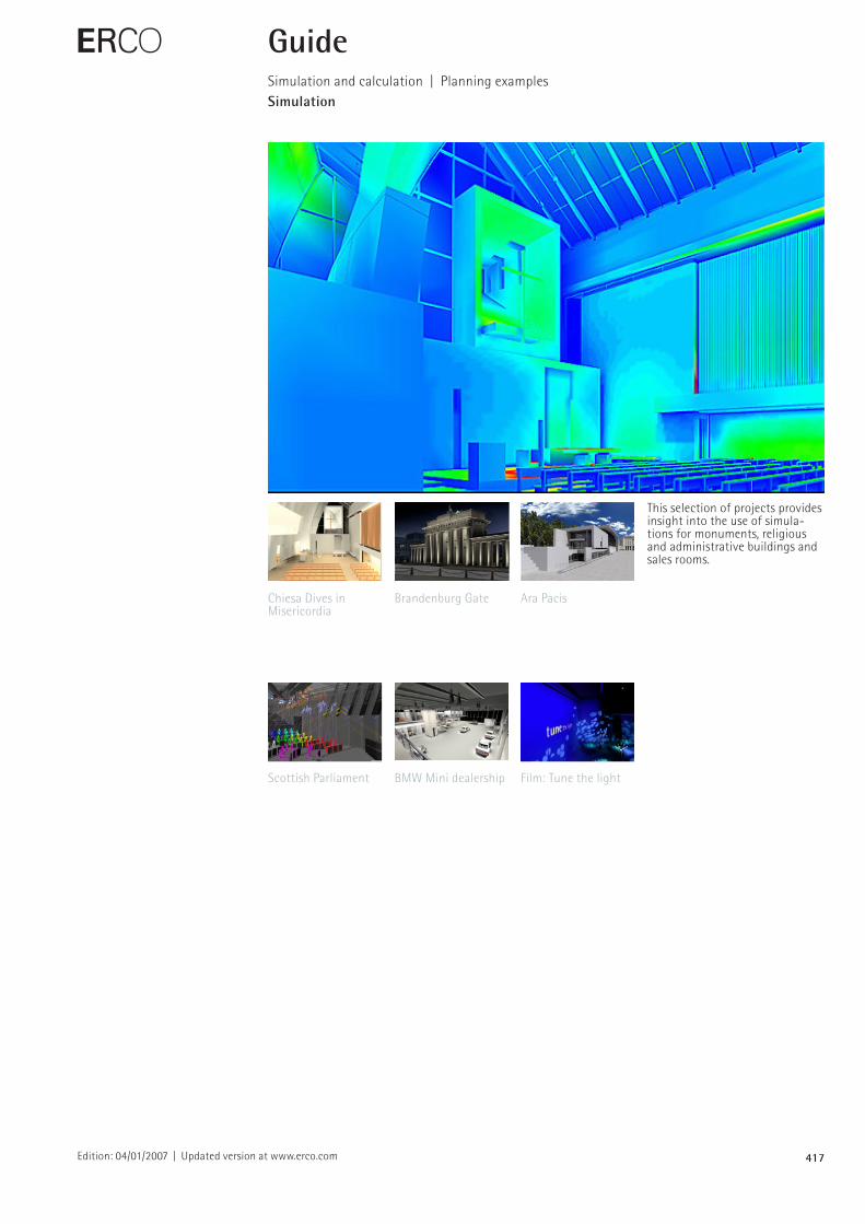
This selection of projects provides insight into the use of simulations for monuments, religious and administrative buildings and sales rooms.
E GuideSimulation and calculation | Planning examplesSimulation
Chiesa Dives in Misericordia
Brandenburg Gate Ara Pacis
Scottish Parliament BMW Mini dealership Film: Tune the light
418Edition: 04/01/2007 | Updated version at www.erco.com
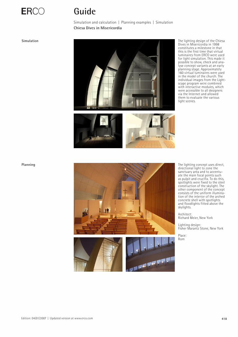
Simulation The lighting design of the Chiesa Dives in Misericordia in 1998 constitutes a milestone in that this is the first time that virtual luminaires from ERCO were used for light simulation. This made it possible to show, check and analyse concept variants at an early planning stage. Approximately 160 virtual luminaires were used in the model of the church. The individual images from the Lightscape program were combined with interactive modules, which were accessible to all designers via the Internet and allowed them to evaluate the various light scenes.
E
Planning The lighting concept uses direct, directional light to zone the sanctuary area and to accentuate the main focal points such as pulpit and crucifix. To do this, spotlights were fixed to the steel construction of the skylight. The other component of the concept consists of the uniform illumination of the interior of the arched concrete shell with spotlights and floodlights fitted above the skylights.
Architect:Richard Meier, New York
Lighting design:Fisher Marantz Stone, New York
Place:Rom
GuideSimulation and calculation | Planning examples | SimulationChiesa Dives in Misericordia
419Edition: 04/01/2007 | Updated version at www.erco.com
E GuideSimulation and calculation | Planning examples | SimulationBrandenburg Gate
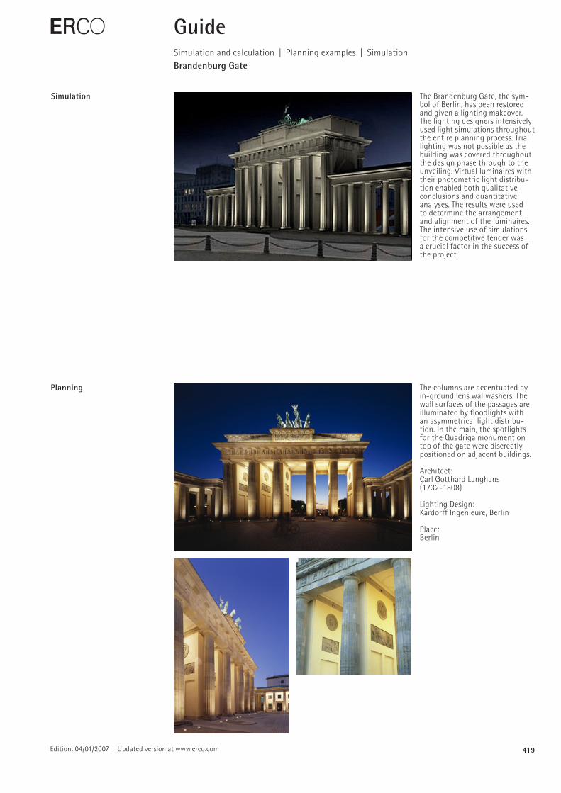
Simulation The Brandenburg Gate, the symbol of Berlin, has been restored and given a lighting makeover. The lighting designers intensively used light simulations throughout the entire planning process. Trial lighting was not possible as the building was covered throughout the design phase through to the unveiling. Virtual luminaires with their photometric light distribution enabled both qualitative conclusions and quantitative analyses. The results were used to determine the arrangement and alignment of the luminaires. The intensive use of simulations for the competitive tender was a crucial factor in the success of the project.
Planning The columns are accentuated by inground lens wallwashers. The wall surfaces of the passages are illuminated by floodlights with an asymmetrical light distribution. In the main, the spotlights for the Quadriga monument on top of the gate were discreetly positioned on adjacent buildings.
Architect:Carl Gotthard Langhans (17321808)
Lighting Design:Kardorff Ingenieure, Berlin
Place:Berlin
420Edition: 04/01/2007 | Updated version at www.erco.com
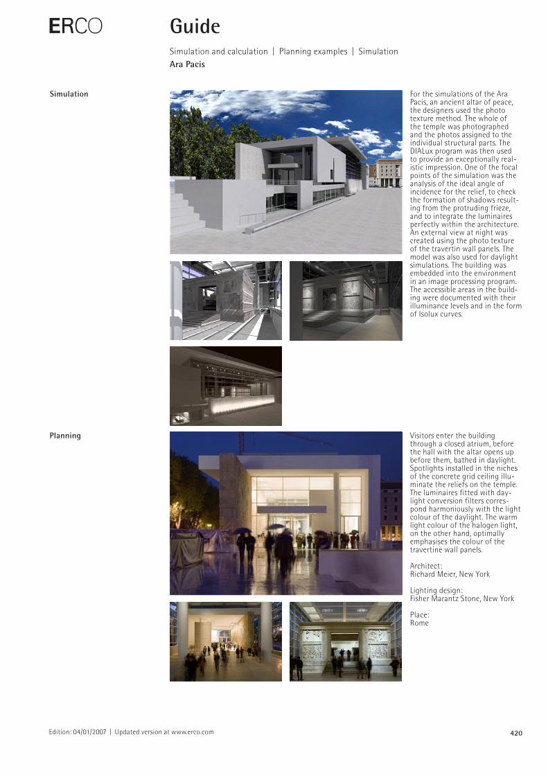
Simulation For the simulations of the Ara Pacis, an ancient altar of peace, the designers used the photo texture method. The whole of the temple was photographed and the photos assigned to the individual structural parts. The DIALux program was then used to provide an exceptionally realistic impression. One of the focal points of the simulation was the analysis of the ideal angle of incidence for the relief, to check the formation of shadows resulting from the protruding frieze, and to integrate the luminaires perfectly within the architecture. An external view at night was created using the photo texture of the travertin wall panels. The model was also used for daylight simulations. The building was embedded into the environment in an image processing program. The accessible areas in the building were documented with their illuminance levels and in the form of Isolux curves.
E
Planning Visitors enter the building through a closed atrium, before the hall with the altar opens up before them, bathed in daylight. Spotlights installed in the niches of the concrete grid ceiling illuminate the reliefs on the temple. The luminaires fitted with daylight conversion filters correspond harmoniously with the light colour of the daylight. The warm light colour of the halogen light, on the other hand, optimally emphasises the colour of the travertine wall panels.
Architect:Richard Meier, New York
Lighting design:Fisher Marantz Stone, New York
Place:Rome
GuideSimulation and calculation | Planning examples | SimulationAra Pacis
421Edition: 04/01/2007 | Updated version at www.erco.com
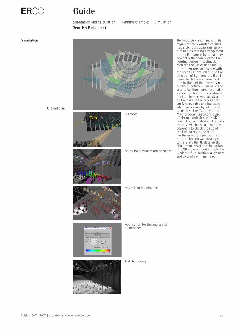
Simulation The Scottish Parliament with its asymmetrically vaulted ceilings, its visible roof supporting structure and its seating arrangement for the Parliament has a complex geometry that complicated the lighting design. This situation required the use of light simulations to ensure compliance with the specifications relating to the direction of light and the illuminance for television broadcasts. Due to the fact that the varying distances between luminaire and area to be illuminated resulted in substantial brightness contrasts, the illuminance was calculated on the basis of the faces at the conference table and increased, where necessary, by additional luminaires. The “Autodesk 3ds Max” program enabled the use of virtual luminaires with 3D geometries and photometric data records, which also allowed the designers to check the size of the luminaires in the room.For the execution phase, a separate application was developed to translate the 3D data on the 900 luminaires of the simulation into 2D drawings and provide the luminous flux, position, alignment and view of each luminaire.
E GuideSimulation and calculation | Planning examples | SimulationScottish Parliament
Ground plan
3D model
Study for luminaire arrangement
Analysis of illuminance
Application for the analysis of illuminance
Test Rendering
422Edition: 04/01/2007 | Updated version at www.erco.com
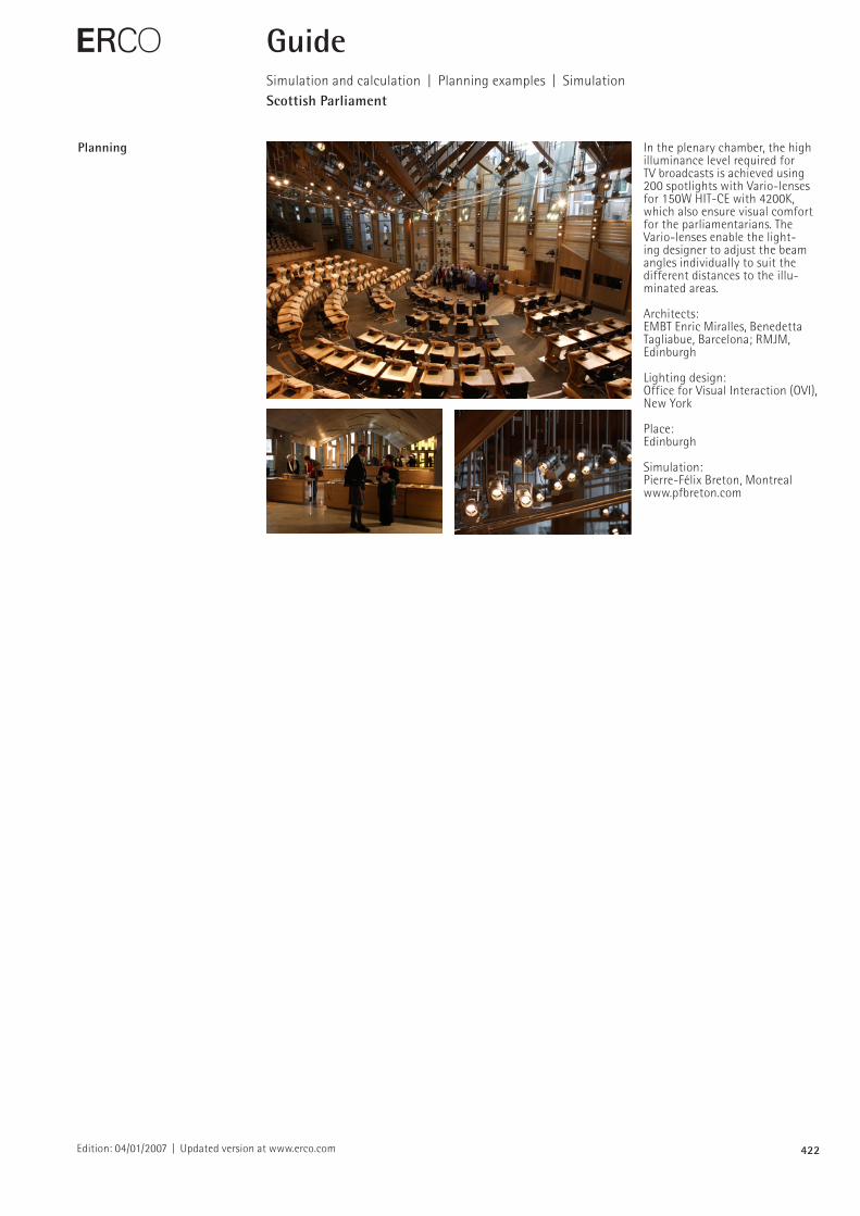
Planning In the plenary chamber, the high illuminance level required for TV broadcasts is achieved using 200 spotlights with Variolenses for 150W HITCE with 4200K, which also ensure visual comfort for the parliamentarians. The Variolenses enable the lighting designer to adjust the beam angles individually to suit the different distances to the illuminated areas.
Architects:EMBT Enric Miralles, Benedetta Tagliabue, Barcelona; RMJM, Edinburgh
Lighting design:Office for Visual Interaction (OVI), New York
Place:Edinburgh
Simulation:PierreFélix Breton, Montrealwww.pfbreton.com
E GuideSimulation and calculation | Planning examples | SimulationScottish Parliament
423Edition: 04/01/2007 | Updated version at www.erco.com
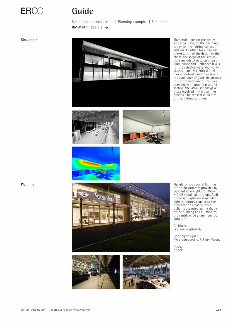
Simulation The simulations for the dealership were used, on the one hand, to review the lighting concept and, on the other, for a realistic presentation of the design to the client. The scope of the simulations included the calculation of illuminance and luminance levels for the vehicles, walls and workspaces to analyse critical luminance contrasts and to evaluate the avoidance of glare. In contrast to the exclusive use of technical drawings with ground plan and section, the visualisations gave those involved in the planning process a better spatial picture of the lighting solution.
E
Planning The glarefree general lighting of the showroom is provided by pendant downlights for 150W HITCE metal halide lamps. Additional spotlights on suspended light structures emphasise the presentation areas. A row of uplights accentuates the shape of the building and illuminates the cantilevered aluminium roof structure.
Architect:Scaramuzza/Rubelli
Lighting designer:Piero Comparotto, Arkilux, Verona
Place:Brescia
GuideSimulation and calculation | Planning examples | SimulationBMW Mini dealership
424Edition: 04/01/2007 | Updated version at www.erco.com
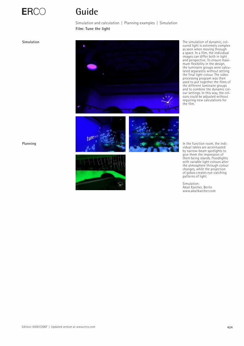
Simulation The simulation of dynamic, coloured light is extremely complex as seen when moving through a space. In a film, the individual images can differ both in light and perspective. To ensure maximum flexibility in the design, the luminaire groups were calculated separately without setting the final light colour. The video processing program was then used to put together the films of the different luminaire groups and to combine the dynamic col our settings. In this way, the colours could be adjusted without requiring new calculations for the film.
E
Planning In the function room, the individual tables are accentuated by narrowbeam spotlights to give them the impression of them being islands. Floodlights with variable light colours alter the atmosphere through colour changes, while the projection of gobos creates eyecatching patterns of light.
Simulation:Aksel Karcher, Berlinwww.akselkarcher.com
GuideSimulation and calculation | Planning examples | SimulationFilm: Tune the light
425Edition: 04/01/2007 | Updated version at www.erco.com
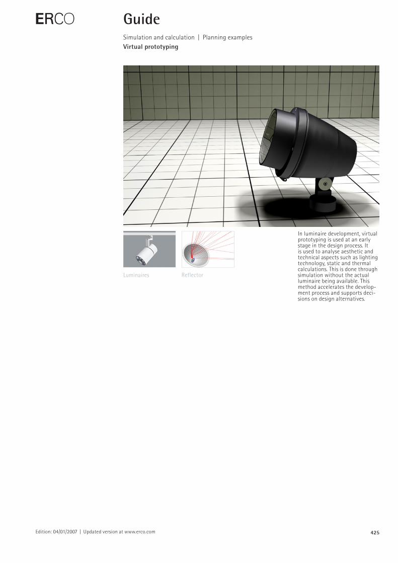
In luminaire development, virtual prototyping is used at an early stage in the design process. It is used to analyse aesthetic and technical aspects such as lighting technology, static and thermal calculations. This is done through simulation without the actual luminaire being available. This method accelerates the development process and supports decisions on design alternatives.
E GuideSimulation and calculation | Planning examplesVirtual prototyping
Luminaires Reflector
426Edition: 04/01/2007 | Updated version at www.erco.com
E GuideSimulation and calculation | Planning examples | Virtual prototypingLuminaires
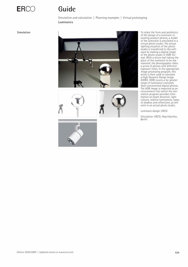
Simulation To relate the form and aesthetics of the design of a luminaire to existing product photos, a model of the luminaire is simulated in a virtual photo studio. The actual lighting situation of the photo studio is transferred to the software by making a digital image of the photo studio in HDR format. With a mirror ball taking the place of the luminaire to be represented, the photographer takes a series of photos with different exposure times. In the appropriate image processing program, this series is then used to calculate a High Dynamic Range Image (HDRI). HDRI covers a far greater range of luminance contrasts than conventional digital photos. The HDR image is imported as an environment into which the simulation program provides information on beam direction, light colours, relative luminances, types of shadow and reflections, as will exist in an actual photo studio.
Luminaire design: ERCO
Simulation: ERCO; Aksel Karcher, Berlin
427Edition: 04/01/2007 | Updated version at www.erco.com
E GuideSimulation and calculation | Planning examples | Virtual prototypingReflector
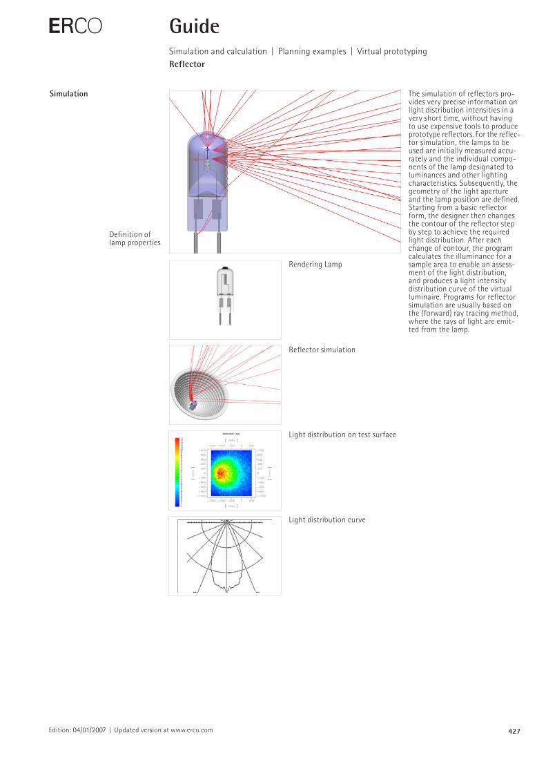
Simulation The simulation of reflectors provides very precise information on light distribution intensities in a very short time, without having to use expensive tools to produce prototype reflectors. For the reflector simulation, the lamps to be used are initially measured accurately and the individual components of the lamp designated to luminances and other lighting characteristics. Subsequently, the geometry of the light aperture and the lamp position are defined. Starting from a basic reflector form, the designer then changes the contour of the reflector step by step to achieve the required light distribution. After each change of contour, the program calculates the illuminance for a sample area to enable an assessment of the light distribution, and produces a light intensity distribution curve of the virtual luminaire. Programs for reflector simulation are usually based on the (forward) ray tracing method, where the rays of light are emitted from the lamp.
Definition of lamp properties
Rendering Lamp
Reflector simulation
Light distribution on test surface
Light distribution curve