simulation-based fluid-thermal analysis of power transformers
TRANSCRIPT

1. Introduction
The economic reliability of power trans-former changes dramatically with its ther-mal performance. Renewed interests in improving the heat-induced failure mod-els have steered the manufacturers and re-searchers towards application of advanced thermal modelling techniques that use highly efficient numerical approximation and visually-aided simulation-based so-lution approach. Two widely acclaimed meth ods for transformer thermal assess-
ment are Thermal-Hydraulic Network Modell ing (THNM) and Computational Fluid Dynamics (CFD). Their sole objec-tive is to predict the oil-winding temper-ature rise and improve the winding-HST displacement predictions without com-promising the capital cost.
These methods are realistic, cost-effec-tive, scientifically accurate, and efficient in improving transformer performance through real-time simulations of multi-ple interdependent physical phenomena,
Simulation-based fluid-thermal analysis of power transformersCritical reviews on advanced thermal assessment
80
ABSTRACT The transformer life and performance strongly depend on winding hot-spot temperature (HST). Various alterna-tive techniques for HST prediction are gain ing popularity over the con-ventional direct-measurement meth-ods. In this context, the application of Computa tional Fluid Dynamics (CFD) based thermal models is particularly interesting because of their accurate assessment, higher precision and low cost. Besides, it can remarkably evalu-ate and improve the design efficiency of transformer without overshooting the capital cost. In the present work, a comprehensive understanding of CFD-based fluid-thermal assessment is attempted to encourage the readers to review transformer thermal models. It is also expected that these attempts will progressively assist in correlating various economical and operational parameters of transformer manufac-turing and asset management.
KEYWORDSoil-filled transformers, cooling, hot-spot, thermal assessment, Comput-a tional Fluid Dynamics
TRANSFORMERS MAGAZINE | Volume 5, Issue 1
EVENTSEVENTSTECHNOLOGY
80

which ultimately affects the temperature rise and HST evaluation. The attractive aspects of such methods include reli-able estimation of the magnitude of in-ternal heat, effect of coolant oil pattern and transformer configuration, and most significantly, its solution technique. Fig-ure 1 is a representation of key aspects in CFD-based thermal modelling of any transform er.
The upcoming sections of this article will assist the reader to gain a comprehensive understanding about CFD-based ther-mal modelling of an oil-filled transformer through an in-depth analysis of the conco-mitant multiphysics, application and limi-tations.
2. CFD-based thermal modelling: Key aspectsThe accuracy of any CFD-based assess-ment improves inherently with proper understanding of governing physics and a potential solution technique. Therefore, pertinent information about the key as-pects propelling a CFD-based assessment includes: calculation domain, governing physics and meshing scheme [1]. As we move forward, we will understand the physical significance of each of these as-pects in detail.
2.1 Calculation domain
A 3D investigation of the equipment’s thermal behaviour is undoubtedly the best incentive to assess, optimize and im-prove its functionality and in-service life. However, such an assessment not only requires pertinent information about
The transformer life and performance strongly depend on winding hotspot temperature
Thermal simulations are a step forward in comprehensive un der stand ing of tem p erature rise phe no me na within trans formers with respect to localized heat ing and buoyancy-driv en flows
Simulation-based fluid-thermal analysis of power transformers
Figure 1. Representation of key aspects of CFD-based thermal modelling of transformers
a) Precise meshing of interactive area;b) Analyzing the governing physics;c) Evaluating the effect of winding configuration;d) Proposing the temperature in 2D or 3D design
a)
b)
d)
c)
www.transformers-magaz ine .com 81
Sruti CHAKRABORTY, Manish VASHISHTHA, Sushil CHAUDHARI

*The equations are in vector representation, where the dot “.” represents multiplication of a scalar with a vector having spatially changing values.
c)
a)
b)
transformer construction, but also be-comes tiresome if one is solely interested in examining the winding thermal per-formance as shown in Figure 2.
In the present work, exclusive discussions are presented on the CFD applications in improving the design of core-type trans-formers containing disc windings. Previ-ous CFD-based attempts on estimating the impact of winding geometry on flow distribution reveals that the complex la-byrinth of radial and axial channels in disc windings is responsible for mixed convection, thermal streaking and HST disposition with respect to buoy ancy changes [1, 2, 5, 6, 8, 9]. This clearly in-dicates that apart from the transformer construction and operating conditions, interactive winding geometry strongly influences the transformer thermal be-haviour.
2.2 Governing equations and bound-ary conditions
Classical combination of Navier-Stokes with energy conservation equations governs the fluid-thermal assessment of transformers by conservation of mass, momentum and energy, as shown below:
[∂ρ/∂t+((u.∇ ).ρ)]+ρ.(∇.u) = 0 (1)
ρ.[∂u/∂t+((u.∇ ).u)]- ∇.σ = Fv (2)
ρ.[∂E/∂t+((u.∇ E)]- ∇.(ks∙ΔTs)+p.∇u –Qs= 0* (3)
Since oil is weakly-compressible, despite an infinitesimally small density variation (β∙∆Tf «1), the viscous flow will become strong enough to allow desired fluid-thermal interactions. This is known as the Boussinesq approximation and expressed mathematically as follows [4]:
Fv = ρ(T)∙g (4)
ρ(T) = ρ0∙[1-β∙∆Tf] (5)
These governing equations require an in-let flow rate and hydrostatic pressure of oil as primary boundary conditions. In this context, oil inlet velocity can be obtained from an energy balance equation, where-as the inlet pressure of oil can be obtained by evaluating the hydrostatic pressure dif-ference between the top and bottom of windings as shown below [7]:
u0 = Qs/(Ac∙Cp∙ρ∙∆Tf) (6)
p0 = ρ(T)∙g∙H∙∆Tf (7)
Where:∂ρ/∂t = rate of mass change (kg/m3∙s)∂u/∂t = rate of momentum change (m/s2)∂E/∂t = rate of energy change (W/s)u = vector representing velocity (m/s)ρ = temperature dependent oil density (kg/m3)ρ0 = temperature dependent oil density at average ambient (kg/m3)σ = viscosity tensor (Pa∙s)Fv = viscous body force (N/m3)E = internal energy (W)ks = thermal conductivity of winding material (W/m∙K)Ts = winding thermal gradient (K)Qs = volumetric heat source (W/m3)p = hydrostatic pressure (Pa)Tf = oil temperature (K)g = gravitational acceleration (m/s2)u0 = inlet oil velocity (m/s)p0 = inlet pressure (Pa)Ac = cross sectional area of inlet channel (m2)H = height of winding (m)
2.3 Meshing and grid analysis
The accuracy of any CFD-based assess-ment depends on its meshing precision. Meshing is the spatial discretization of the investigated domain into smaller blocks or cells of definite shapes (e.g. triangular or quadrilateral for 2D geo-metries, and tetrahedral, hexahedral, pyramids, or prisms for 3D geometries). Figure 3 shows a meshing scheme using 2D triangular elements of the investi-gated winding domain.
Previously, Finite Difference Method (FDM) based assessment produces false-time stepping over structured meshes, whereas FDM-based iterative approaches
Apart from the transformer construction and operating conditions, interactive winding geometry strongly influences the transformer thermal behaviour
Figure 2. Simplification of the winding domain for CFD applications by schematic representa-tion of 3D winding, 2D axisymmetric model, and 2D slice model
a) 3D winding;b) 2D axisymmetric model;c) 2D slice model
82 TRANSFORMERS MAGAZINE | Volume 5, Issue 1
TECHNOLOGY

83 www.transformers-magaz ine .com
show divergent patterns while analyzing buoyancy-driven flows. Unlike such loose and oversimplified grids, Finite Volume Method (FVM) not only incorporates a tighter grid, but also refines it continuously to ascertain the independence of physical properties over mesh complexities thereby increasing the solution accuracy, otherwise known as grid analysis [1]. Similar approaches exist within the Finite Element Method (FEM) based CFD environments, namely, COMSOL Multiphysics, Code_Saturne, etc. Both FVM and FEM apply various iterative solvers with suitable algorithms to analyze the proposed problems. Therefore, the solver continues to operate until the solution converges and the truncation error minimizes. The relative tolerance and convergence of FDM and FVM/FEM is approximately 10-3 and 10-6, respectively, thus suggesting relatively tightly-controlled grid.
3. CFD analysis: Parametric investigationsThe CFD-based fluid-thermal assessment of transformers, especially windings, de-pends on winding configuration and flow parameters besides the obvious transform-er operating conditions. In this context, we investigate the effects of various parameters on oil-winding temperature rise and HST disposition on a 2D slice model of disc wind-ings. Torriano et al. [9] provide the config-uration details for a potential case-study on disc windings with various boundary conditions.
3.1 Effect of inflow: Location, magnitude, and pattern
Winding thermal performance strongly depends on flow distribution behaviour within the immediate vicinity of conducting discs. In fact, IEC 60076-2 (1993) suggests that the temperature rise limits and HST can be significantly improved through suitable analysis of oil-flow patterns [10]. In this context, analysis of oil inlet location, width of inlet, inflow velocity and flow pattern are prominent. Figure 4(a) shows that upon changing the inlet location, the temperature rise limits can vary significantly. The effect of location is proposed by observing the inlet at inner (Chin) and outer (Chout) channels respectively, such that oil enters from bottom and exits from top of the winding. If the inlet channel width is
small, then there is a homogeneous mixing of oil near the entrance of winding which decays with increasing entry length, thereby accumulating excess heat near the centre of the winding. This is also why HST exists somewhere in the middle or near the top, if not on the top most disc on the winding. Figure 4(b) shows a sort of a parabolic temperature profile over a finite number of conducting discs, which is due to the parabolic velocity profile and fully developed hydrodynamic boundary layers near the conducting surfaces. The blue line depicts the surface temperature behaviour of conductors when the oil inlet is positioned at the outer channel given by the bottom contour of Figure 4(a). Similarly, the green curve depicts the surface temperature rise behaviour when inlet is located within the inner channel of winding as given by top contour of Figure 4(a). Hence, a complete “bath-tub” temperature curve can be expected from such simulations. Moreover, while a wider inlet channel
(Chin = 8.9 mm) allows lower temp-erature rise limits (HST at 89.92 °C) unlike narrow channels (Chin = 6.4 mm, HST at 92.702 °C), its application is also dominated by the flow calculations. In this particular case, the inner channel is 1.4 times the width of the outer channel as reported elsewhere [9]. At this point, one can easily observe that suitability of the inlet channel width and location depends entirely on the inflow conditions.It is understood that if upstream oil circulation is extremely slow, then buoyancy decreases due to the overwhelming conduction. The resultant low oil velocities are rendered useless and winding heat dissipation fails. Hence, minimum oil velocity must be known to optimize and improve the transformer thermal design. The parametric investigation shown in Figure 5(a) reveals that average oil temperature rises rapidly beyond a certain value. Similar results can be expected to portray average conductor temperature.
The application of CFDbased thermal models is particularly interesting because of their accurate assessment, higher precision and low cost
Figure 3. Various meshing aspects of simulation-based fluid-thermal assessment of windings
a) 2D and 3D mesh elements in FVM and FEM packages;b) Structured meshing near washer;c) Unstructured meshing near washer;d) Free meshing of solid-fluid domain in FEM
a)
b)
c)
d)
www.transformers-magaz ine .com 83

Figure 5. Effect of variable oil velocity on temperature rise behaviour
a) Rise in average oil temperature over outlet length;b) Rise in average winding surface temperature
a)
a)
b)
b)
the 6th and 12th disc from the bottom, the magnitude of HST decreases by almost 5.8 °C when compared to two-pass structure. Washers alter the oil interaction pattern, thereby causing sudden change in temperature of conductor and the oil surrounding it. It is also obvious that despite better cooling efficiency, application of directed cooling is restricted by winding configuration and thus requires further improvement during the thermal assessment.
3.2 Effect of winding design: disc and layer
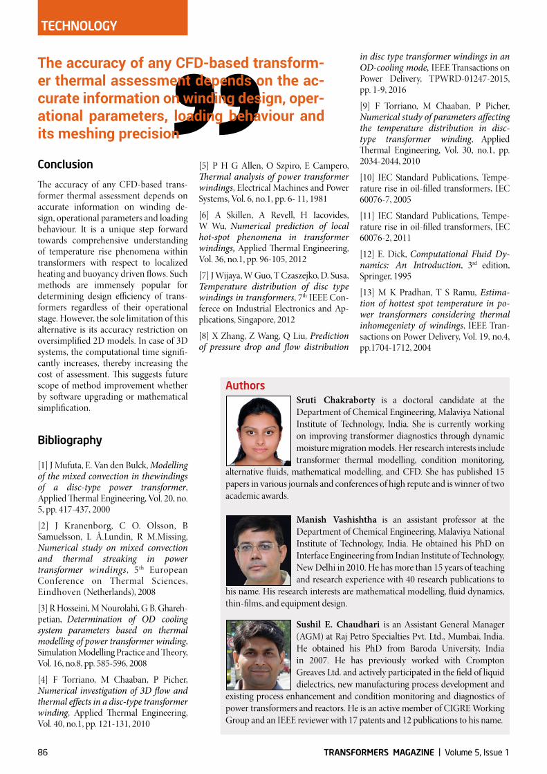
Figure 6 suggests that the transformers are not only distinguished on the basis of core configuration, but also by winding construction. Therefore, accurate information pertaining to winding configuration can influence the accuracy of any simulated assessment. Although a comparison between the disc and layer winding thermal profile is not possible because of obvious reasons, we still will try to objectify some of the critical outcomes that may support our hypothesis.
The thermal conductivity of copper and insulates is highly anisotropic [9], which varies for disc and layer arrangement even within the same transformer. This not only affects the heat source and re-sultant temperature calculations, but also affects the magnitude and location of HST formation on the assembly. Spe-cific simulations reveal that while a hot-spot is expected somewhere near the top in case of disc windings, it is always encountered at the top in case of layer windings [12, 13]. However, the accuracy of this observation is yet to be estab lished by further investigations using CFD-based techniques.
Although the scientific literature is abun-dant with various aspects of simulation-based thermal assessment of disc and layer type windings, suitable CFD cali-brations to improve such models using modern day FVM and FEM solvers re-main to be seen.
3.3 Effect of approximation approach
Any discussion on CFD-based assess-ment will remain incomplete without analysing the competency of the nume-
assisted oil flow is referred to as directed cooling, where washer location depends largely on radial duct height, number of discs, oil inlet velocity and transformer cooling pattern.Figure 6(a) shows the application of various blocks and stick washers for improving transformer thermal design. Figure 6(b) shows the effect of stick spacers on winding thermal behaviour using 2D contour plots.The strategic placement of these washers can dramatically reduce the HST magnitude. For example, when three passes are created within the single slice of winding by introducing washers near
It is evident from Figure 5 that without attaining the desired minimum velocity, efficient heat dissipation cannot be achieved. For example, if we apply very high velocity (u >0.059 m/s) to a relatively thinner inlet channel, the average surface temperature will increase due to non-uniform mixing throughout the entry length. Maintaining uniform oil velocity across the winding height is equally significant, without which local heat accumulation and “heat-pool” formation can occur. To overcome this, pressboard washers (in the form of sticks and blocks) are strategically placed within the axial and radial channels of windings. Washer
Figure 4. Effect of inlet location and inlet channel width on temperature rise limits and HST
a) 2D plots depicting the effect of inlet location;b) 1D plots depicting the effect of inlet location
If upstream oil circulation is extremely slow, then buoyancy decreases due to the overwhelming conduction
84 TRANSFORMERS MAGAZINE | Volume 5, Issue 1
TECHNOLOGY
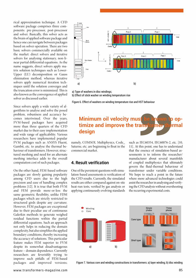
Figure 6. Effect of washers on winding temperature rise and HST behaviour
a) Type of washers in disc windings;b) Effect of stick washer on winding temperature rise
a)
a) b)
b)
rical approximation technique. A CFD software package comprises three com-ponents: pre-processor, post-processor and solver. Basically, this solver acts as the brain of applied software package and hence one can navigate between packages based on solver operation. There are two basic solvers commercially available on the market: direct solvers and iterative solvers for analysing stationary, non-li-near partial differential equations. As the name suggests, direct solvers apply ma-trix solution techniques such as Lower-Upper (LU) decomposition or Gauss elimination method, whereas iterative solvers apply numerical iteration tech-niques until the solution converges and the truncation error is minimized. This is also known as the convergence of applied solver as discussed earlier.
Since solvers apply a wide variety of al-gorithms to analyse and solve the p osed problem, robustness and accuracy be-comes intertwined. Over the years, FVM-based packages have acquired more than three quarters of the CFD market due to their easy implementation and wide range of applicability. Various research ers have implemented popular FVM packages such as ANSYS Fluent, Gambit, etc. to analyse the thermal be-haviour of transformers. However, struc-tured mesh ing and need for an alternate meshing interface adds to the overall computation cost of such packages.
On the other hand, FEM-based software packages are slowly gaining popularity among CFD users due to the high precision and ease of handling complex problems [12]. It is true that both FVM and FEM provide more-or-less the same geometric flexibility, unlike FDM packages which are strictly restricted to structured girds despite any curvature. However, FEM packages are exceptional due to their peculiar use of continuous Galerkin methods to generate weighed residual functions within the partial differential equations. Such an approach not only helps in reducing the domain complexity, but also simplifies the applied boundary conditions, thereby increasing the accuracy of solutions. This particular feature makes FEM superior to FVM despite its somewhat disadvantageous feature – domain dependence. Currently researchers are feverishly trying to improve such pitfalls of FEM-based packages and improved versions;
namely, COMSOL Multiphysics, Code_Saturne, etc. are beginning to float in the commercial market.
4. Result verification
One of the persistent questions with simu-lation-based assessments is verification of the CFD results. Currently, the simulated results are either compared against on-site heat-run tests, verified by gas analysis or applying continuously evolving standards
such as IEC60354, IEC60076-2, etc. [10, 11]. At this point, one has to understand that the essence of simulation-based as-sessments is to inform the researcher/manu facturer about several manifolds of coupled multiphysics that ultimately govern the fluid-thermal behaviour of transformer under variable conditions. We hope to reach a point in the future w here more advanced technologies could assist the researcher in analysing and verify-ing the CFD analysis without overshoot ing the recurring experimental costs.
Minimum oil velocity must be known to optimize and improve the transformer thermal design
Figure 7. Various core and winding constructions in transformers: a) layer winding; b) disc winding
www.transformers-magaz ine .com 85
in disc type transformer windings in an OD-cooling mode, IEEE Transactions on Power Delivery, TPWRD-01247-2015, pp. 1-9, 2016
[9] F Torriano, M Chaaban, P Picher, Numerical study of parameters affecting the temperature distribution in disc-type transformer winding, Applied Thermal Engineering, Vol. 30, no.1, pp. 2034-2044, 2010
[10] IEC Standard Publications, Tempe-rature rise in oil-filled transformers, IEC 60076-7, 2005
[11] IEC Standard Publications, Tempe-rature rise in oil-filled transformers, IEC 60076-2, 2011
[12] E. Dick, Computational Fluid Dy-namics: An Introduction, 3rd edition, Springer, 1995
[13] M K Pradhan, T S Ramu, Estima-tion of hottest spot temperature in po-wer transformers considering thermal inhomegeniety of windings, IEEE Tran-sactions on Power Delivery, Vol. 19, no.4, pp.1704-1712, 2004
[5] P H G Allen, O Szpiro, E Campero, Thermal analysis of power transformer windings, Electrical Machines and Power Systems, Vol. 6, no.1, pp. 6- 11, 1981
[6] A Skillen, A Revell, H Iacovides, W Wu, Numerical prediction of local hot-spot phenomena in transformer windings, Applied Thermal Engineering, Vol. 36, no.1, pp. 96-105, 2012
[7] J Wijaya, W Guo, T Czaszejko, D. Susa, Temperature distribution of disc type windings in transformers, 7th IEEE Con-ferece on Industrial Electronics and Ap-plications, Singapore, 2012
[8] X Zhang, Z Wang, Q Liu, Prediction of pressure drop and flow distribution
Conclusion
The accuracy of any CFD-based trans-former thermal assessment depends on accurate information on winding de-sign, operational parameters and loading behaviour. It is a unique step forward towards comprehensive understanding of temperature rise phenomena within transformers with respect to localized heating and buoyancy driven flows. Such methods are immensely popular for determining design efficiency of trans-formers regardless of their operational stage. However, the sole limitation of this alternative is its accuracy restriction on oversimplified 2D models. In case of 3D systems, the computational time signifi-cantly increases, thereby increasing the cost of assessment. This suggests future scope of method improvement whether by software upgrading or mathematical simplification.
Bibliography
[1] J Mufuta, E. Van den Bulck, Modelling of the mixed convection in thewindings of a disc-type power transformer, Applied Thermal Engineering, Vol. 20, no. 5, pp. 417-437, 2000
[2] J Kranenborg, C O. Olsson, B Samuelsson, L Å.Lundin, R M.Missing, Numerical study on mixed convection and thermal streaking in power transformer windings, 5th European Conference on Thermal Sciences, Eindhoven (Netherlands), 2008
[3] R Hosseini, M Nourolahi, G B. Ghareh-petian, Determination of OD cooling system parameters based on thermal modelling of power transformer winding, Simulation Modelling Practice and Theory, Vol. 16, no.8, pp. 585-596, 2008
[4] F Torriano, M Chaaban, P Picher, Numerical investigation of 3D flow and thermal effects in a disc-type transformer winding, Applied Thermal Engineering, Vol. 40, no.1, pp. 121-131, 2010
The accuracy of any CFDbased transformer thermal assessment depends on the accurate information on winding design, operational parameters, loading behaviour and its mesh ing precision
AuthorsSruti Chakraborty is a doctoral candidate at the Department of Chemical Engineering, Malaviya National Institute of Technology, India. She is currently working on improving transformer diagnostics through dynamic moisture migration models. Her research interests include transformer thermal modelling, condition monitoring,
alternative fluids, mathematical modelling, and CFD. She has published 15 papers in various journals and conferences of high repute and is winner of two academic awards.
Manish Vashishtha is an assistant professor at the Department of Chemical Engineering, Malaviya National Institute of Technology, India. He obtained his PhD on Interface Engineering from Indian Institute of Technology, New Delhi in 2010. He has more than 15 years of teaching and research experience with 40 research publications to
his name. His research interests are mathematical modelling, fluid dynamics, thin-films, and equipment design.
Sushil E. Chaudhari is an Assistant General Manager (AGM) at Raj Petro Specialties Pvt. Ltd., Mumbai, India. He obtained his PhD from Baroda University, India in 2007. He has previously worked with Crompton Greaves Ltd. and actively participated in the field of liquid dielectrics, new manufacturing process development and
existing process enhancement and condition monitoring and diagnostics of power transformers and reactors. He is an active member of CIGRE Working Group and an IEEE reviewer with 17 patents and 12 publications to his name.
86 TRANSFORMERS MAGAZINE | Volume 5, Issue 1
TECHNOLOGY