simulation driven optimized mechanism drive - ansys · simulation driven optimized mechanism drive...
TRANSCRIPT
© 2011 ANSYS, Inc. August 30, 20111
Simulation Driven Optimized Mechanism Drive
Elias Taye, PhDWm Wrigley Jr. CompanySubsidiary of Mars Inc.
August 30, 2011

© 2011 ANSYS, Inc. August 30, 20112
AGENDA Introduction of Wm Wrigley Jr. Company
Original Design of the Mechanical Linkage Objective of Simulation Rigid Dynamic Analysis Transient Structural Analysis Issues
First Design Optimization Objective of Simulation Rigid Dynamic Analysis Transient Structural Analysis 1st Optimization Summary
Second Design Optimization Objective of Simulation Rigid Dynamic Analysis Transient Structural Analysis 2nd Optimization Summary
Experimental Validation of Actuator Driven Mechanical Linkage Conclusion
© 2011 ANSYS, Inc. August 30, 20113
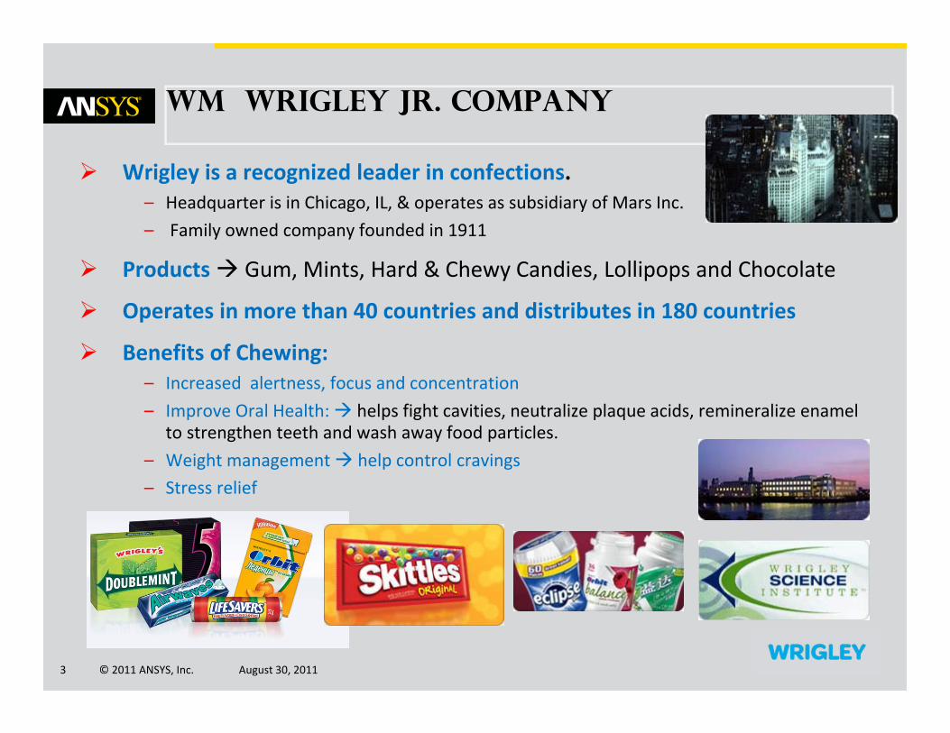
Wrigley is a recognized leader in confections. – Headquarter is in Chicago, IL, & operates as subsidiary of Mars Inc.– Family owned company founded in 1911
Products Gum, Mints, Hard & Chewy Candies, Lollipops and Chocolate
Operates in more than 40 countries and distributes in 180 countries
Benefits of Chewing:– Increased alertness, focus and concentration– Improve Oral Health: helps fight cavities, neutralize plaque acids, remineralize enamel
to strengthen teeth and wash away food particles.– Weight management help control cravings– Stress relief
Wm Wrigley Jr. Company

© 2011 ANSYS, Inc. August 30, 20114
ORIGINAL DESIGN
Mechanism Has one rotational input that further splits into two different translation motions All components are made of structural steel
Boundary Condition Input: Angular Rotation of cam shaft (0) Constraints: Applied joints between rigid & flexible bodies
Objective of modeling: Calculate the Shaking Force, Bearing load and structural
stiffness for current speed (0) To model the mechanism for high speed (2x0)

© 2011 ANSYS, Inc. August 30, 20115
Original design
Simulation Results and Issues Has high max. Shaking Force 464 Lbf (2063N) Has high max. Driving Torque 590 Lbf‐ft (800Nm) Cam generating the vertical motion has the max load The cams have harmonic motion profile
– The jerk function is infinite at dwell ends– Has sudden change in acceleration
This is a source for vibration and noise The Fork performs a triangular motion
– abrupt of smooth motion Stresses are within the material strength limit
Transfer Fork Total Reaction Force, 600 RPM
-1500
-1000
-500
0
500
1000
1500
2000
2500
0 60 120 180 240 300 360
Rotation (°)
Forc
e (N
)
FxFyFzSum
Shaking ForceInput Torque
Fork Motion Profile
590Lbf‐ft590Lbf‐ft
2063N2063N

© 2011 ANSYS, Inc. August 30, 20116
1st design optimization - cam
Objective: Reduce Dynamic Load1. Redesign both Cams2. Improve Fork motion profile
1. Cam Synthesis Current Design Harmonic Cams
– Sudden change of acceleration at dwell– The jerk function is infinite at dwell two jerks per revolution this generates vibration & noise
New Design Cycloidal Cams– NO Sudden change in acceleration– Used for high speed application– Very low vibration– Jerk function is finite across the entire 360° interval – The first and second derivatives of displacement are continuous – reduces the dynamic inertia of machine

© 2011 ANSYS, Inc. August 30, 20117
1st design optimizationRedesign linkage & Motion profile
2. Optimizing Fork Motion Profile Understand existing motion profile Eliminate the abrupt motion and redesignnew cams timing
Modified Motion Profile
Original Motion Profile
3. Redesign Linkage To reduce bearing load To fit within packaging constrain on horizontal direction
© 2011 ANSYS, Inc. August 30, 20118
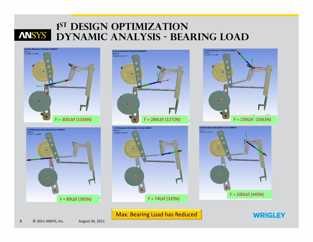
1st design Optimization dynamic analysis - Bearing Load
F = 305Lbf (1356N) F = 286Lbf (1272N) F = 239Lbf (1063N)
F = 89Lbf (395N) F = 89Lbf (395N) F = 74Lbf (329N) F = 74Lbf (329N) F = 100Lbf (445N) F = 100Lbf (445N)
Max. Bearing Load has Reduced
© 2011 ANSYS, Inc. August 30, 20119
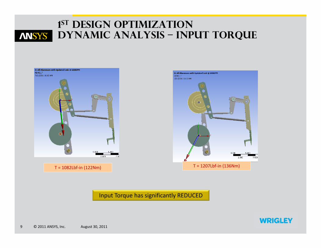
1st design Optimization dynamic analysis – Input torque
T = 1082Lbf‐in (122Nm) T = 1207Lbf‐in (136Nm)
Input Torque has significantly REDUCED

© 2011 ANSYS, Inc. August 30, 201110
1st design Optimization kinematic analysis
Calculated also Speed & Acceleration at each Kinematic Pairs
These are important information for the next Design Optimization
1 = 8.0679° 2 = 13.057° 3 = 22.3174°

© 2011 ANSYS, Inc. August 30, 201111
1st design Optimization Transient structural Analysis
Fork Displacement Max. VM Stress = 8.56E6Pa (1241psi)

© 2011 ANSYS, Inc. August 30, 201112
1st design Optimization Transient structural Analysis
Max. VM Strain = 0.0001 Max. Normal Stress9.16E6Pa (1347psi)
Max Principal Stress 1.138E7Pa (1673psi)
The stresses are way below the material strength limit Aluminum material 7075‐T6 (y ~ 36000psi)

© 2011 ANSYS, Inc. August 30, 201113
1st design Optimization - animation
Mechanism Animation

© 2011 ANSYS, Inc. August 30, 201114
1st Optimization summary
Analysis Result Dynamic load has reduced significantly Less bearing load Less input torque requirement observed less vibration/ noise Replaced the structural steel by Aluminum material Better Space usage behind the machine frame The improved fork motion profile (rectangular vs. triangular) reduces
the dynamic load
ANSYS Rigid Body Dynamic and Transient Structural Analysis have greatly helped us to improve our design within a short period of time. The final design of the First Design Optimization is built and installed in our machine.

© 2011 ANSYS, Inc. August 30, 201115
2nd Optimization Electronic Camming
Mechanical Cams are replaced by Electronic Camming
Servos Timing in angular position is calculated to
produce the same motion profile Results obtained from Rigid Body Dynamic Without ANSYS it would be difficult to extract this important
information
Developed Prototype
Pros of Servo Driven Mechanism Less mechanical components Less inertia Simplified design Less power, torque and current consumption Better position control
© 2011 ANSYS, Inc. August 30, 201116
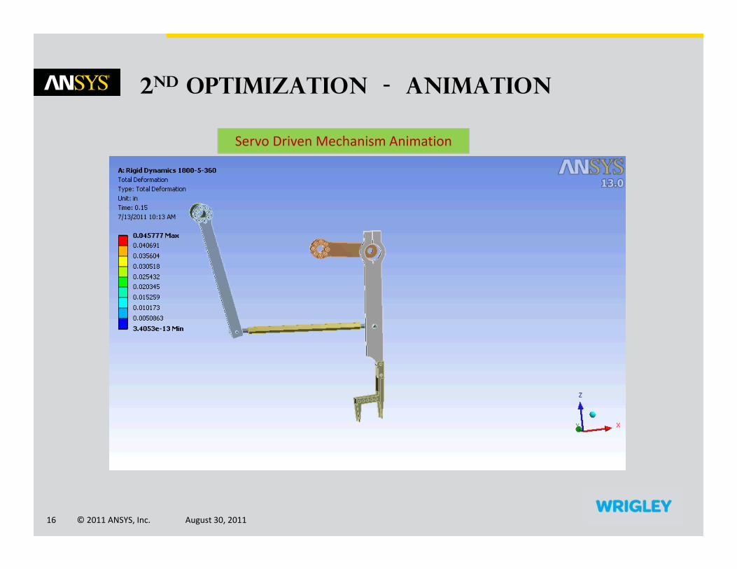
2nd Optimization - Animation
Servo Driven Mechanism Animation

© 2011 ANSYS, Inc. August 30, 201117
2nd Optimization electronic Camming
Defining Cam Timing
Developed cam timing as a function of time Converted the timing to drive machine (master axis) angular position Modified the cam timing

© 2011 ANSYS, Inc. August 30, 201118
2nd Optimization Transient structural Analysis
VM Strain = 5.637e‐5 Von Mises Stress4.0E6Pa (588 psi)
Max Principal Stress 3.256E6Pa (479 psi)
The stresses are way below the material strength limitAluminum material 7075‐T6 (y ~ 36000psi)

© 2011 ANSYS, Inc. August 30, 201119
2nd Optimization Dynamic Analysis
F = 17Lbf (75N) F = 25Lbf (111N) F = 87Lbf (386N)
F = 29Lbf (129N) V = 42in/sec V = 90 in/sec
Bearing Load has Reduced significantly even without optimizing the linkage

© 2011 ANSYS, Inc. August 30, 201120
experimental validation
Front View of Test SetupFront View of Test Setup
Rear View of Test SetupRear View of Test Setup
Yaskawa Servo Control Test BenchYaskawa Servo Control Test Bench

© 2011 ANSYS, Inc. August 30, 201121
experimental validation video clip
SLOW SPEED run of Servo HIGH SPEED run of Servo

© 2011 ANSYS, Inc. August 30, 201122
experimental validation Modal analysis
At higher speed the motor starts chattering due to overload Lower Rated Motor Torque
Conducted Modal Analysis to make sure that the component or system is not operating close to its natural frequencies Excited frequencies are not close to its natural frequencies
309 Hz 309 Hz 622 Hz 622 Hz 1525 Hz 1525 Hz
6th Mode6th Mode 1st Mode1st Mode 4th Mode4th Mode

© 2011 ANSYS, Inc. August 30, 201123
2nd design optimization - conclusion
The Servo Driven Mechanism Design has been validated and showed significant improvement compared to Original & 1st Design Optimization
The prototype is designed to replace the existing mechanical cam linkagefor proof of concept has potential for further optimizing the linkage the mass can be reduced up to 60% or more which eventually reduces the dynamic
load of the system
The Servo Design has Less mechanical components Less inertial mass Less power, torque and current consumption
– this leads to cost reduction Very low vibration and noise
The Optimized Servo Design will be used in our new high speed machine.

© 2011 ANSYS, Inc. August 30, 201124
THANK YOU