simulation modeling of the multi-axle truck dynamics · to model the vehicle dynamics we used cad...
TRANSCRIPT

Abstract— Experimental and theoretical researches and
operation experience show that the acceleration dynamics,
mobility and fuel efficiency of wheeled vehicles are
considerably influenced by the circuit of power input to the
traction wheels. It is particularly important to multiwheelers,
for example, off-road dump trucks. To insure a high off-road
performance of any vehicle the power distribution along the
wheels must meet two basic requirements: 1) the wheel must
operate in a free or close to it rolling mode with the minimum
rolling resistance due to absence of an axial force and an
absolute slip; 2) in case it is necessary to create an axial
pulling power to overcome additional resistances
(acceleration, rise, towed load), the power supplied to the
wheel must not exceed the limit of the intensive ground
failure as a result of excessive wheel slipping. In other words,
wheel slipping must not exceed the value, at which the
maximum pulling power is created. To obtain consistent
results of the vehicle’s dynamic processes the authors
developed a mathematic model, which includes a description
of all the vehicle’s basic systems with real parameters. The
created mathematical model allowed to implement the
vehicle’s motion processes for all the required motion modes
in view of the dynamics of the vehicle’s major units and
subsystems. To model the vehicle dynamics we used CAD
LMS AMESim package of physically-oriented mathematical
modeling.
Index Terms— All-wheel drive vehicles, control of
movement, modeling, stability.
I. INTRODUCTION
FF-ROAD dump trucks are generally operated at
different road conditions, on asphalt, dirt road or
The work was supported by Act 211 Government of the Russian
Federation, contract № 02.A03.21.
The work was conducted with the financial support of the Ministry of
Education and Science of the Russian Federation in the framework of the
complex project to create a high-tech production "Creating high-tech
production of a new generation of energy efficient transmissions for
trucks and buses" under contract No. 02.G25.31.0142 dated "01"
December 2015 between the Ministry of Education and Science of the
Russian Federation and Public Joint-Stock Company "KAMAZ" in
cooperation with the head executor of the research, development and
technological work of civil purpose - Federal State Autonomous
Educational Institution of Higher Education "South Ural State University
(National Research University)".
A. V. Keller is with the South Ural State University, 76 Prospekt
Lenina, Chelyabinsk, 454080, Russian Federation (e-mail:
V. A. Sayakhov is with the South Ural State University, 76 Prospekt
Lenina, Chelyabinsk, 454080, Russian Federation (e-mail:
S. V. Aliukov is with the South Ural State University, 76 Prospekt
Lenina, Chelyabinsk, 454080, Russian Federation (corresponding author,
home phone: +7-351-267-97-81; sell phone: 8-922-6350-198; e-mail:
sand. Mechanical power losses are registered in the vehicle
at all the stages of power transfer. However, the power
needed to overcome the motion resistance can be reduced
by choosing an optimal traction wheel drive circuit. Thus,
it is possible to increase the vehicle performance [1].
The power consumed on the rolling resistance can
considerably grow in different road conditions. In this
regard, the losses for the traction wheel rolling differ from
the losses for the idle wheel rolling. It is connected with
the fact that losses for outward rolling are added to
hysteresis losses (equally inherent in the idle wheel). It, in
its turn, depends on the torque supplied to the wheel. To
reduce the wheel torque at preservation of the vehicle’s
traction force it is necessary to increase the number of
traction wheels. Apart from the losses for the traction
wheel slipping with regard to the bearing surface, it is also
necessary to consider the power necessary for rotation of
the units of the additional drive axle and the drive thereto.
In this regard, the transmission losses are increased with
the increasing number of traction wheels, and the losses for
slipping of the traction wheels with regard to the bearing
surface are decreased with the increasing number of the
traction wheels.
It is possible to obtain reliable data on energy losses
during the vehicle movement by means of experiments.
Alongside with that, the experiments involve considerable
financial expenses. In this connection, currently the
researchers apply the simulation modeling method [2, 3,
4]. Mathematical models allow to obtain the necessary
vehicle characteristics without any experiments at the
design stage, that is why they have been actively used by
motor manufacturers.
II. OBJECT OF RESEARCH
The object of the research is KAMAZ-65222 off-road
dump truck (Figure 1), specifications (Table I) [8] and
design drive circuits (Figure 2, 3) [1].
Fig. 1. KAMAZ-65222 dump truck
Simulation Modeling of the Multi-Axle Truck
Dynamics
A. Keller, V. Sayakhov and S. Aliukov
O
Proceedings of the World Congress on Engineering 2017 Vol II WCE 2017, July 5-7, 2017, London, U.K.
ISBN: 978-988-14048-3-1 ISSN: 2078-0958 (Print); ISSN: 2078-0966 (Online)
WCE 2017

TABLE I
SPECIFICATIONS OF KAMAZ-6522 Weight parameters and loads
Curb weight, kg 14350
load on the rear bogie, kg 8000
load on the front axle, kg 6350
Full weight of the vehicle, kg 34000
load on the rear bogie, kg 26000
load on the front axle, kg 8000
Engine
Engine model 740.632-400
Gearbox
Transmission model ZF 16S1820
Drive gear
Transmission ratio 6,88
Climbing angle, no less than, % 25
External turning radius, m 12
Fig. 2. Design drive circuits
(1,2,3 – Simmetrical differentials; 4 – Simmetrical locking differential;
5 – Asymetrical locking differential; 6,7– overriding clutches).
III. DESCRIPTION OF THE MATHEMATICAL
To obtain reliable results of the vehicle’s dynamic
processes the mathematical model must include a
description of all the vehicle’s basic systems with real
parameters of the research object. The design pattern of a
vehicle with forces acting in the linear motion mode is
shown in Figure 3.
To model the vehicle dynamics we use CAD (package
of physically-oriented mathematical modeling) LMS
AMESim. The created mathematical model allows us to
implement the vehicle’s motion processes for all the
required motion modes in view of the dynamics of the
vehicle’s major units and subsystems.
The general view of the model is shown in Figure 4.
This model consists of all the most important subsystems:
engine, transmission, suspension and body. It describes all
the necessary physical characteristics of the vehicle and the
environment: weight and inertia, force of the wheel’s
interaction with the road carpet, aerodynamic resistance,
etc.
The transmission units and motion conditions influence
the truck body. Let us write the equations for the body’s
motion [4]:
where, – vehicle’s slew rate; – total sprung weight;
– vehicle’s weight; - height to the center of gravity;
– banking angle; - longitudinal speed; – lateral
speed; – body’s inertia moment; - wheel’s
longitudinal response; - wheel’s lateral response; –
distance between the front axle and the center of gravity;
– distance between the center of gravity and the
intermediate axle; - distance between the center of
gravity and the rear axle; - width of the front track; –
width of the rear track.
“The driver model” consists of a set of logical
elements. It solves the following tasks: position control of
the throttle blade, clutch pedal, brake pedal, choosing the
transmission speed of the gearbox and the turn angle of the
steering wheel.
The power unit and the transmission include: engine,
which characteristics depend on the position of the throttle
blade, configured to evaluate fuel efficiency; clutch model,
connection/disconnection are controlled by the clutch
pedal; model of the 16-speed synchronized gearbox and
the transfer case with asymmetric locking differential and
ability to disconnect of the front axle, as well as drive axles
with symmetric inter-wheel differentials and the symmetric
locking inter-axle differential of the intermediate and the
rear axle.
The front axle suspension model and the rear bogie
center point suspension model consider the dynamics of
the solid axle’s operating process, quench oscillations of
the carrier system and transfer power and moments thereto,
which occur when the wheels interact with the road. The
embedded model of Brixius/Dugoff tires [5, 6] ensures
interaction of the wheel with the deformable bearing
surface, while the dependency of the friction coefficient on
the spin is a hyperbolical function.
The developed model allowed us to evaluate efficiency
of the truck’s power distribution with 6х6 and 6х4 drive
circuit with regard to the motion resistance powers [7]:
66
46
N
NKef ,
where, 46N – total vehicle’s motion resistance power
with circuit 6x4 ;
66N – total vehicle’s motion resistance power with
circuit 6x6.
Proceedings of the World Congress on Engineering 2017 Vol II WCE 2017, July 5-7, 2017, London, U.K.
ISBN: 978-988-14048-3-1 ISSN: 2078-0958 (Print); ISSN: 2078-0966 (Online)
WCE 2017

Fig. 3. Force pattern at linear motion
(G – Vehicle’s center of gravity (CG); XYZ – axes of the global
coordinate system; Pj ,Py – axes of the local coordinate system beginning
in the vehicle’s CG; Rxij – axial wheel force; Ryij – lateral wheel force;
RZij – normal wheel force; crij – wheel damping coefficient; kri – wheel
rigidity coefficient; cpij – suspension damping coefficient; kpi –
suspension rigidity coefficient; Pw – aerodynamic resistance force).
The main operating conditions of mine dump trucks
[9,10] are descends and rises along roads of different slope
levels and different support and adhesion properties, as
well as roll-outs and turnovers to considerable angles. A
full description of modeling scenarios is presented in Table
II.
Fig. 4. Mathematical model made in LMS Imagine.Lab Amesim
(1 – Driver model; 2 – Vehicle chassis model; 3 – Engine model; 4 –
Clutch model; 5 – Gearbox model; 6 – Transfer gear model; 7 – Front
axle model; 8 – Intermediate axle model; 9 – Rear axle model; 10 –
Model of the wheel and its interaction with the bearing surface; 11 –
Front axle suspension model; 12 – Read bogie centerpoint suspension
model).
TABLE II
MODELING SCENARIOS
Rise up the road slope (climbing aslope at the
previously gathered speed)
Weight of the
trailing load, Т
19,5; 9,725; 0
Axle
arrangement
6x6; 6х4
Climbing
angle,%
up to 40
Road
conditions
Asphaltic concrete road; dirt
road: dry rolled, after rain; dry sand
Position of the
throttle blade
Full open
IV. RESULTS
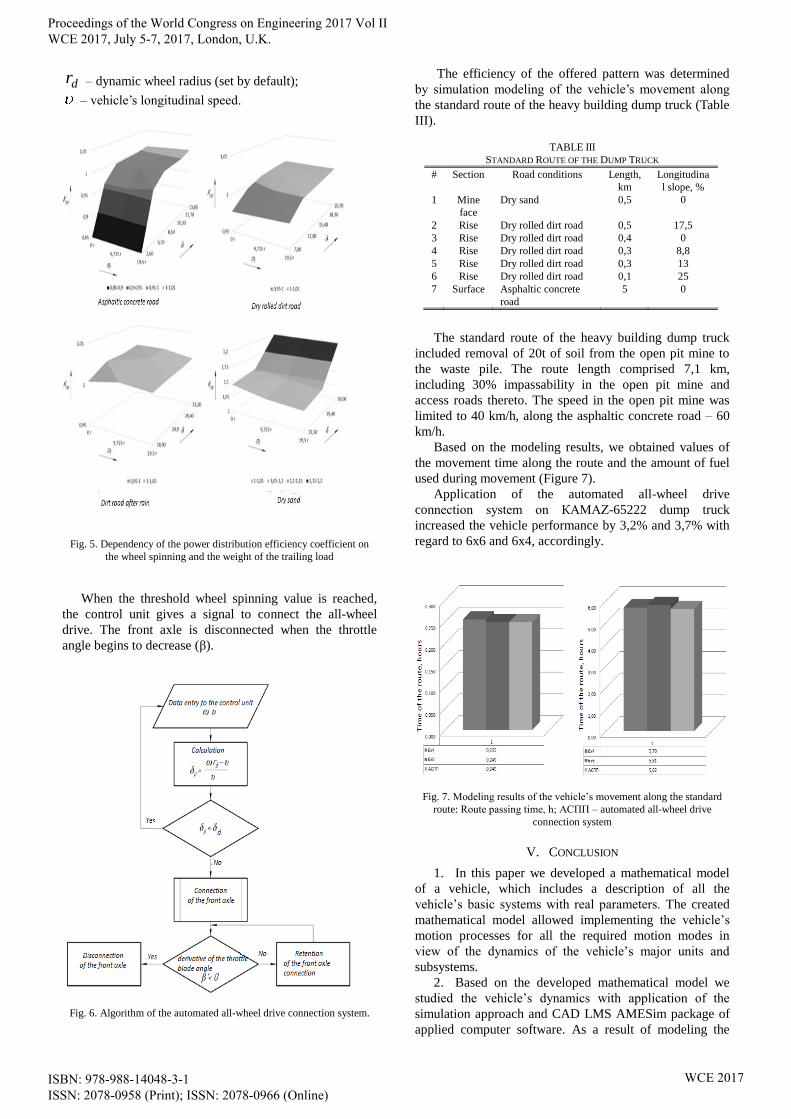
As a result of modeling the movement along road
sections with different types of road carpet and slopes we
obtained dependencies of the power distribution efficiency
coefficient on the wheel spinning and the weight of the
trailing load (Figure 5).
In the course of an analysis of the obtained results we
defined the threshold value of the wheel spinning of the
rear bogie of the vehicle moving with the “disconnected”
front axle, when it is expedient to change-over to the all-
wheel drive power distribution pattern.
Based on the aforesaid, it is proposed to increase power
and fuel efficiency of trucks by application of the
automated all-wheel drive connection system.
The algorithm of the offered system is shown in figure
6. When the vehicle is moving, its motion speed and angle
speeds of the traction wheels are continuously controlled.
The control unit defines the traction wheel spinning by the
following expression:
dr,
where, – angle wheel speed;
Proceedings of the World Congress on Engineering 2017 Vol II WCE 2017, July 5-7, 2017, London, U.K.
ISBN: 978-988-14048-3-1 ISSN: 2078-0958 (Print); ISSN: 2078-0966 (Online)
WCE 2017
dr – dynamic wheel radius (set by default);
– vehicle’s longitudinal speed.
Fig. 5. Dependency of the power distribution efficiency coefficient on
the wheel spinning and the weight of the trailing load
When the threshold wheel spinning value is reached,
the control unit gives a signal to connect the all-wheel
drive. The front axle is disconnected when the throttle
angle begins to decrease (β).
Fig. 6. Algorithm of the automated all-wheel drive connection system.
The efficiency of the offered pattern was determined
by simulation modeling of the vehicle’s movement along
the standard route of the heavy building dump truck (Table
III).
TABLE III
STANDARD ROUTE OF THE DUMP TRUCK
# Section Road conditions Length,
km
Longitudina
l slope, %
1 Mine
face
Dry sand 0,5 0
2 Rise Dry rolled dirt road 0,5 17,5
3 Rise Dry rolled dirt road 0,4 0
4 Rise Dry rolled dirt road 0,3 8,8
5 Rise Dry rolled dirt road 0,3 13
6 Rise Dry rolled dirt road 0,1 25
7 Surface Asphaltic concrete
road
5 0
The standard route of the heavy building dump truck
included removal of 20t of soil from the open pit mine to
the waste pile. The route length comprised 7,1 km,
including 30% impassability in the open pit mine and
access roads thereto. The speed in the open pit mine was
limited to 40 km/h, along the asphaltic concrete road – 60
km/h.
Based on the modeling results, we obtained values of
the movement time along the route and the amount of fuel
used during movement (Figure 7).
Application of the automated all-wheel drive
connection system on КАМАZ-65222 dump truck
increased the vehicle performance by 3,2% and 3,7% with
regard to 6x6 and 6x4, accordingly.
Fig. 7. Modeling results of the vehicle’s movement along the standard
route: Route passing time, h; АСПП – automated all-wheel drive
connection system
V. CONCLUSION
1. In this paper we developed a mathematical model
of a vehicle, which includes a description of all the
vehicle’s basic systems with real parameters. The created
mathematical model allowed implementing the vehicle’s
motion processes for all the required motion modes in
view of the dynamics of the vehicle’s major units and
subsystems.
2. Based on the developed mathematical model we
studied the vehicle’s dynamics with application of the
simulation approach and CAD LMS AMESim package of
applied computer software. As a result of modeling the
Proceedings of the World Congress on Engineering 2017 Vol II WCE 2017, July 5-7, 2017, London, U.K.
ISBN: 978-988-14048-3-1 ISSN: 2078-0958 (Print); ISSN: 2078-0966 (Online)
WCE 2017

movement along road sections with different types of road
carpet and slopes we obtained the dependencies of the
power distribution efficiency coefficient on the wheel
spinning and the weight of the trailing load.
3. We defined the threshold value of the wheel
spinning of the rear bogie of the vehicle moving with the
“disconnected” front axle, when it is expedient to change-
over to the all-wheel drive power distribution pattern.
Based on the obtained results, we proposed to increase
energy and fuel efficiency of trucks by application of the
automated all-wheel drive connection system.
REFERENCES
[1] González-Cruz, C., Jáuregui-Correa, J., López-Cajún, C. et al.,
"Dynamic Behavior and Synchronization of an Automobile as a
Complex System," ASME 45837, vol.1, 2014.
[2] Annicchiaricom, C., Rinchi, M., Pellari, S. and Capitani, R.,
"Design of a Semi Active Differential to Improve the Vehicle
Dynamics," ASME 45837, vol.1, 2014.
[3] Assadian, F., Hancock, M., Herold, Z., Deur, J. et al., "Modeling
and Experimental Validation of Active Limited Slip Differential
Clutch Dynamics," ASME 48784, 2008, pp. 295-304.
[4] Vantsevich, V. and Shyrokau, B., "Autonomously Operated Power-
Dividing Unit for Driveline Modeling and AWD Vehicle Dynamics
Control," ASME 43352, 2008, pp. 891-898.
[5] Keller, A., Aliukov, S., Anchukov, V. and Ushnurcev, S.,
"Investigations of Power Distribution in Transmissions of Heavy
Trucks," SAE Technical Paper 2016-01-1100, 2016,
doi:10.4271/2016-01-1100.
[6] Keller, A., Murog, I. and Aliukov, S., "Comparative Analysis of
Methods of Power Distribution in Mechanical Transmissions and
Evaluation of their Effectiveness," SAE Technical Paper 2015-01-
1097, 2015, doi:10.4271/2015-01-1097.
[7] Keller, A. and Aliukov, S., "Rational Criteria for Power
Distribution in All-wheel-drive Trucks," SAE Technical Paper
2015-01-2786, 2015, doi:10.4271/2015-01-2786.
[8] Keller, A. and Aliukov, S., "Analysis of Possible Ways of Power
Distribution in an All-Wheel Drive Vehicle," in Lecture Notes in
Engineering and Computer Science: World Congress on
Engineering 2015, pp. 1–5.
[9] Dubrovskiy, A., Aliukov, S., Keller, A., Dubrovskiy, S. et al.,
"Adaptive Suspension of Vehicles with Wide Range of Control,"
SAE Technical Paper 2016-01-8032, 2016, doi:10.4271/2016-01-
8032.
[10] Keller, A., Aliukov, S., Anchukov, V., and Ushnurcev, S.,
"Investigations of Power Distribution in Transmissions of Heavy
Trucks," SAE Technical Paper 2016-01-1100, 2016,
doi:10.4271/2016-01-1100.
Proceedings of the World Congress on Engineering 2017 Vol II WCE 2017, July 5-7, 2017, London, U.K.
ISBN: 978-988-14048-3-1 ISSN: 2078-0958 (Print); ISSN: 2078-0966 (Online)
WCE 2017